

TGB EST 1000 Service Manual
EST 1000
SERVICE MANUAL
TAIWAN GOLDEN BEE CO.,LTD.
This service manual contains the technical data of each component
inspection and repairs for the Blade 1000. The manual is
shown with illustrations and focused on “Service Procedures”,
“Operation Key Points”, and “Inspection Adjustment” so that provides
technician with service guidelines.
If the style and construction of the Blade 1000 are different
from that of the photos, pictures shown in this manual, the actual
vehicle shall prevail. Specifications are subject to change without
notice.
This service manual describes basic information of different system
parts and system inspection & service for Blade 1000. In
addition, please refer to the manual contents in detailed for the
model you serviced in inspection and adjustment.
Please see the content for quick having the special parts and system
information.

1 GENERAL INFORMATION
2 SERVICE MAINTENANCE INFORMATION
5-4 TRANSMISSION BEAR BOX
5-5 CONTINUOUSLY VARIABLE TRANSMISSION
1. GENERAL INFORMATION
PAGE
3 LUBRICATION SYSTEM
4-1 FUEL SYSTEM
4-2 FUEL INJECTION SYSTEM
5-1 ENGINE ASSEMBLY
5-2 ENGINE TOP END
CONTENT
5-3 ENGINE BOTTOM END
6 DRIVE SYSTEM
7-1 STEERING SYSTEM & SUSPENSION
7-2 ELECTRIC POWER STEERING
7-3 BRAKE SYSTEM & BODY COVER
8-1 ELECTRIC SYSTEM
8-2 ELECTRIC DIAGRAM
1-2

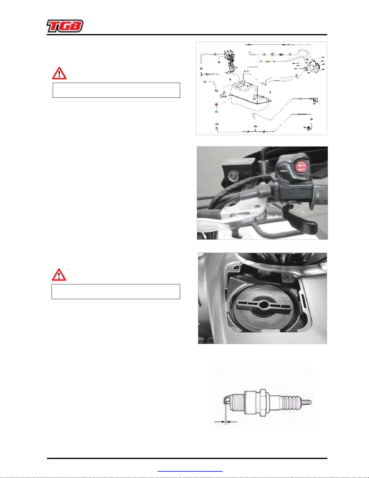
SERIAL NUMBER
Frame Number and Engine Number
TST*000001*
1. GENERAL INFORMATION
1-3
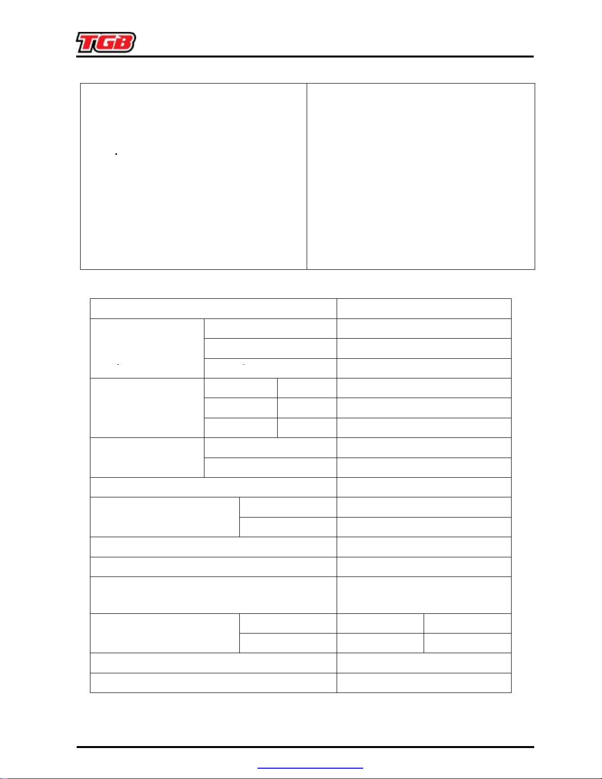
2. MAINTENANCE INFORMATION
Precautions in Operation ······················ 2-1
Periodical Maintenance Schedule ·········2-2
Fuel Lines ············································· 2-3
Acceleration Operation ························· 2-3
Air Cleaner············································ 2-3
Spark Plug ············································ 2-3
Valve Clearance ··································· 2-4
Carburetor Idle Speed Adjustment········ 2-5
Ignition System ······································2-6
Cylinder Compression Pressure ·········· 2-6
Drive Belt ············································· 2-7
Specification
Fuel Tank Capacity
Oil & Filter Change
Engine Oil
Oil change
New Engine
Brake System (Disk Brake) ················· 2-8
Brake Light Switch/Starting Inhibitor
Switch ·················································· 2-9
Headlight Beam Distance ···················· 2-10
Clutch Disc Wear ································· 2-10
Cushion················································· 2-10
Steering Handle···································· 2-11
Wheel/Tire············································· 2-11
Nuts, Bolts Tightness ··························· 2-11
Special Tools List ································· 2-12
2300 c.c.
2000 c.c.
1800 c.c.
2300 c.c.
Transmission Gear oil
Capacity of coolant
Clearance of throttle valve
Spark Plug
Idling speed
Cylinder compression pressure
Valve clearance
Tire dimension
Tire pressure
Bear Box Capacity
Front Capacity
Rear Capacity
Engine + Radiator
Reservoir upper
Type
Gap
Front
Rear
900 cc
350 c.c.
500 c.c.
2600 c.c.
IN:0.10 ± 0.02 mm EX:0.15 ± 0.02
AT25x8-12 AT26x8-14
AT25x10-12 AT26x10-14
1100 c.c.
1~3 mm
NGK DCPR8E
0.7~0.8
1250±100 rpm
9 ±1 kgf/cm²
mm
7 psi
mm
Battery
PDF created with pdfFactory Pro trial version www.pdffactory.com
12V18Ah (type : MF battery)
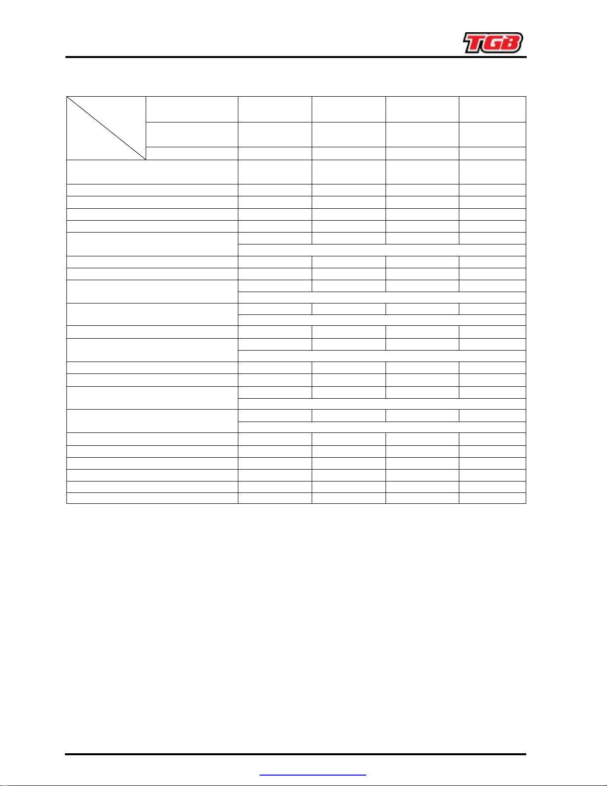
2. MAINTENANCE INFORMATION
Periodical Maintenance Schedule
INTERVAL
ITEM
Muffler Bolts and Exhaust Pipe Nuts
Valve Clearance I - I I
Air Cleaner - C C R
Air Cleaner Vent Tube I I I
Engine Idle RPM I I I I
Spark Plus
Engine Oil R - R R
Oil Filter R - R R
Front Differential Set Oil
Final Gear Oil
C.V.T Belt - - I I
Fuel Tube
Throttle Cable Play I I I I
Brakes I I I I
Brake Hose
Brake Fluid
Tires - I I I
Suspensions - - I I
Steering System I I I I
Chassis Bolts and Nuts T T T T
General Lubrications - L L L
Grease nipple - - L L
MONTHS 1 3 6 12
Kms INITIAL 200 EVERY 1000 EVERY 2000 EVERY 4000
MILES INITIAL 120 EVERY 600 EVERY 1200 EVERY 2400
T T T T
- - I I
Replace Every 6000KM (4000 MILES)
R - R R
Replace Every 6000KM or Every 6 Months
R - R R
Replace Every 6000KM or Every 6 Months
- I I I
Replace Every 4 Years
- - I I
Replace Every 4 Years
- I I I
Replace Every 2 Years
Code: C ~ Cleaning (replaced if necessary) I ~ Inspection, cleaning, and adjustment
L ~ Lubrication R ~ Replacement T ~ Tighten
Have your ATV checked, adjusted, and recorded maintenance data periodically by your TGB
Authorized Dealer to maintain the ATV at the optimum condition.
The above maintenance schedule is established by taking the monthly 1000 kilometers as a
reference which ever comes first.
Remarks:
1. Clean or replace the air cleaner element more often when the ATV is operated on dusty
roads or in the Heavily- polluted environment.
2. Maintenance should be performed more often if the ATV is frequently operated in high
speed and after the ATV has accumulated a higher mileage.
3. Preventive maintenance
a. Ignition system-Perform maintenance and check when continuous abnormal ignition,
misfire, after-burn, overheating occur.
b. Carbon deposit removal-Remove carbon deposits in cylinder head, piston heads,
exhaust system when power is obviously lower than normal.
PDF created with pdfFactory Pro trial version www.pdffactory.com
2. MAINTENANCE INFORMATION
Fuel Lines
Check all lines, and replace it when they are
deterioration, damage or leaking.
For removal, refer to chapter 4 Fuel Pump.
Warning
Gasoline is a low ignition material so any kind
of fire is strictly prohibited as dealing it.
Acceleration Operation
Have a wide open of throttle valve as handle in
any position and release it to let back original
(full closed) position.
Check handle if its operation is smooth.
Check acceleration cable and replace it if
deteriorated, twisted or damaged.
Lubricate the cable if operation is not smooth.
Measure the throttle lever free play in its flange
part.
Remove rubber boot, loosen fixing nut, and
then adjust it by turning the adjustment screw.
Tighten the fixing nut, and check acceleration
operation condition.
Free play: 1~3 mm.
Air Cleaner
Open access cover.
Counterclockwise turn the lid and pull out
the element
Loosen the screw and separate the element.
Clean the sponge with non-flammable or
high-flash point solvent and then squeeze it for
dry.
Caution
Never use gasoline or acid organized solvent
to clean the element.
For installation, reverse the removal procedure.
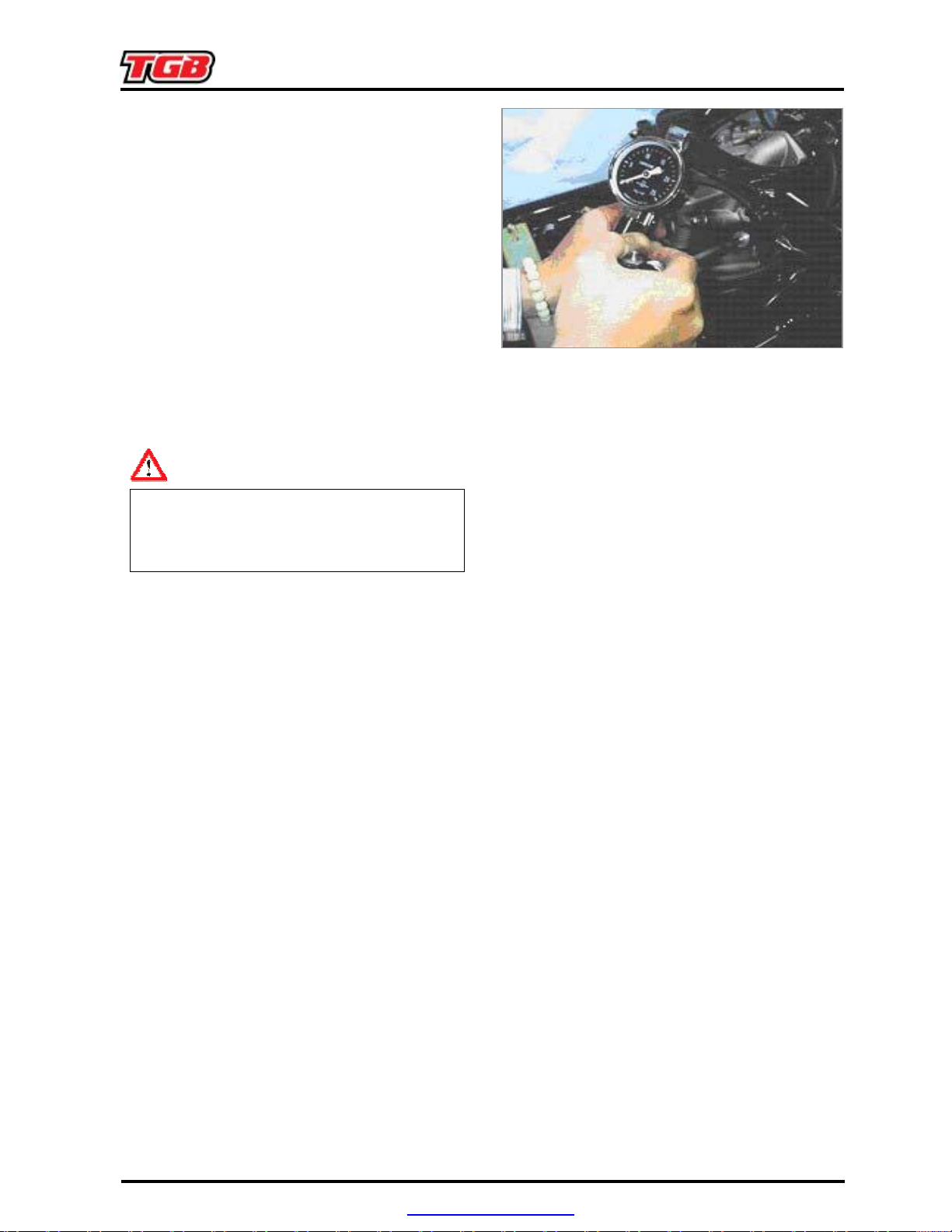
Spark Plug
Recommended spark plug:
NGK
/ DCPR8E
Remove spark plug cap.
Clean dirt around the spark plug hole. Remove
spark plug.
Measure spark plug gap.
Spark plug gap:0.7~0.8 mm
Carefully bend ground electrode of the plug to
adjust the gap if necessary.
Hold spark plug washer and install the spark
plug by screwing it.
Tighten the plug by turning 1/2 turn more with
plug socket after installed.
Tighten torque: 2.0~0.2kgf-m
PDF created with pdfFactory Pro trial version www.pdffactory.com
2. MAINTENANCE INFORMATION
with cylinder head mark so that piston is placed
Valve Clearance
Caution
Checks and adjustment must be performed
when the engine temperature is below 35℃.
Remove front fender, top cover and air cleaner.
Remove cylinder head cover.
Turn camshaft bolt in C.W. direction and let the
Printing mark on the camshaft sprocket align
at TDC position in compression stroke.
Caution
Do not turn the bolt in C.C.W. direction to
prevent from camshaft bolt looseness.
Valve clearance inspection and adjustment.
Check & adjust valve clearance with feeler
gauge.
Loosen fixing nut and turn the adjustment nut
for adjustment.
Standard Value: IN 0.10 ± 0.02 mm
EX 0.15 ± 0.02 mm
Caution
Re-check the valve clearance after tightened
the fixing nut.
PDF created with pdfFactory Pro trial version www.pdffactory.com
2. MAINTENANCE INFORMATION
Ignition System
For ignition system, refer to chapter 5 electric
system.
Cylinder Compression Pressure
Warm up engine.
Turn off the engine.
Remove the top cover.
Remove the side cover.
Remove any one of the spark plug cap and
spark plug.
Install compression gauge.
Full open the throttle valve, and rotate the
engine by means of starter motor.
Caution
●
Rotate the engine until the reading in the
gauge no more increasing.
●
Usually, the highest pressure reading will be
obtained in 4~7 seconds.
Compression pressure: 9.0 ± 2 bar
Check following items if the pressure is too low:
●
Incorrect valve clearance.
●
Valve leaking.
●
Cylinder head leaking, piston, piston ring
and cylinder worn out.
If the pressure is too high, it means carbon
deposits in combustion chamber or piston head.
PDF created with pdfFactory Pro trial version www.pdffactory.com
2. MAINTENANCE INFORMATION
Drive Belt
Remove side cover.
Remove footrest.
Remove bolts of the clutch cover.
Check if the belt is crack or worn out.
Replace the belt if necessary or in accord with
the periodical maintenance schedule to replace
it.
Width limit: 31.0 mm or above
PDF created with pdfFactory Pro trial version www.pdffactory.com
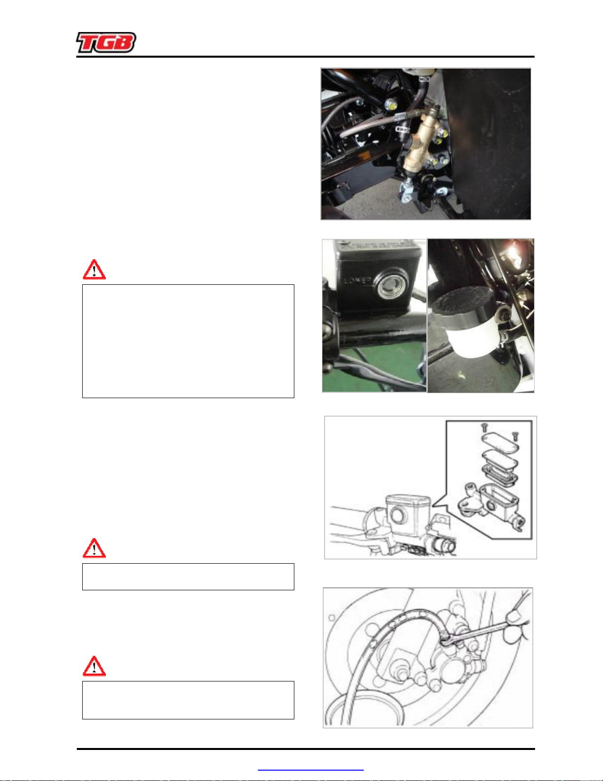
2. MAINTENANCE INFORMATION
In order to maintain brake fluid in the reservoir
Hold the brake lever and open air bleeding valve.
Brake System
Brake System Hose
Make sure the brake hoses for corrosion or
leaking oil.
Brake Fluid
Check brake fluid level in the brake fluid
reservoir.
If the level is lower than the LOWER limit, add
brake fluid to UPPER limit. Also check brake
system for leaking if low brake level found.
Caution
●
in horizontal position, do not remove the cap
until handle stop.
●
Do not operate the brake lever after the
cap had been removed. Otherwise, the
brake fluid will spread out if operated the
lever.
●
Do not mix non-compatible brake fluid
together.
Filling Out Brake Fluid
Tighten the drain valve, and add brake fluid.
Operate the brake lever so that brake fluid
contents inside the brake system hoses.
Air Bleed Operation
Connect a transparent hose to draining valve.
Perform this operation alternative until there is
no air inside the brake system hoses.
Caution
Before closing the air bleed valve, do not
release the brake lever.
Added Brake Fluid
Add brake fluid to UPPER limit lever.
Recommended brake fluid: DOT3 or DOT4
WELL RUN brake fluid.
Caution
Never mix or use dirty brake fluid to prevent
from damage brake system or reducing brake
performance.
PDF created with pdfFactory Pro trial version www.pdffactory.com
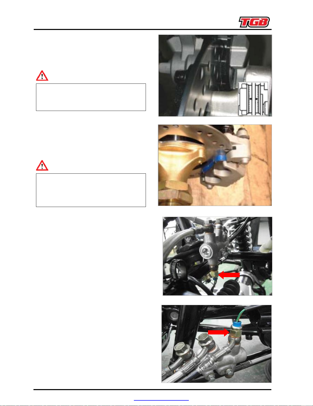
2. MAINTENANCE INFORMATION
In order to maintain brake power balance, the
ght as
Make sure that electrical starter can be operated
Brake
The indent mark on brake lining is the wear
limitation.
Replace the brake lining if the wear limit mark
closed to the edge of brake disc.
Lining Wear
Caution
●
To check front brake lining must be remove
front wheel first.
●
It is not necessary to remove brake hose
when replacing the brake lining.
Brake
Lining
Replacement (refer chapter
7-3)
Make sure the brake lining condition. Replace
the lining if the brake lining wear limitation
groove close to the brake disc.
Caution
●
Do not operate the brake lever after the
clipper removed to avoid clipping the brake
lining.
●
brake lining must be replaced with one set.
Brake Light Switch/Starting
Inhibitor Switch
The brake light switch is to light up brake li
brake applied.
only under brake applying.
PDF created with pdfFactory Pro trial version www.pdffactory.com
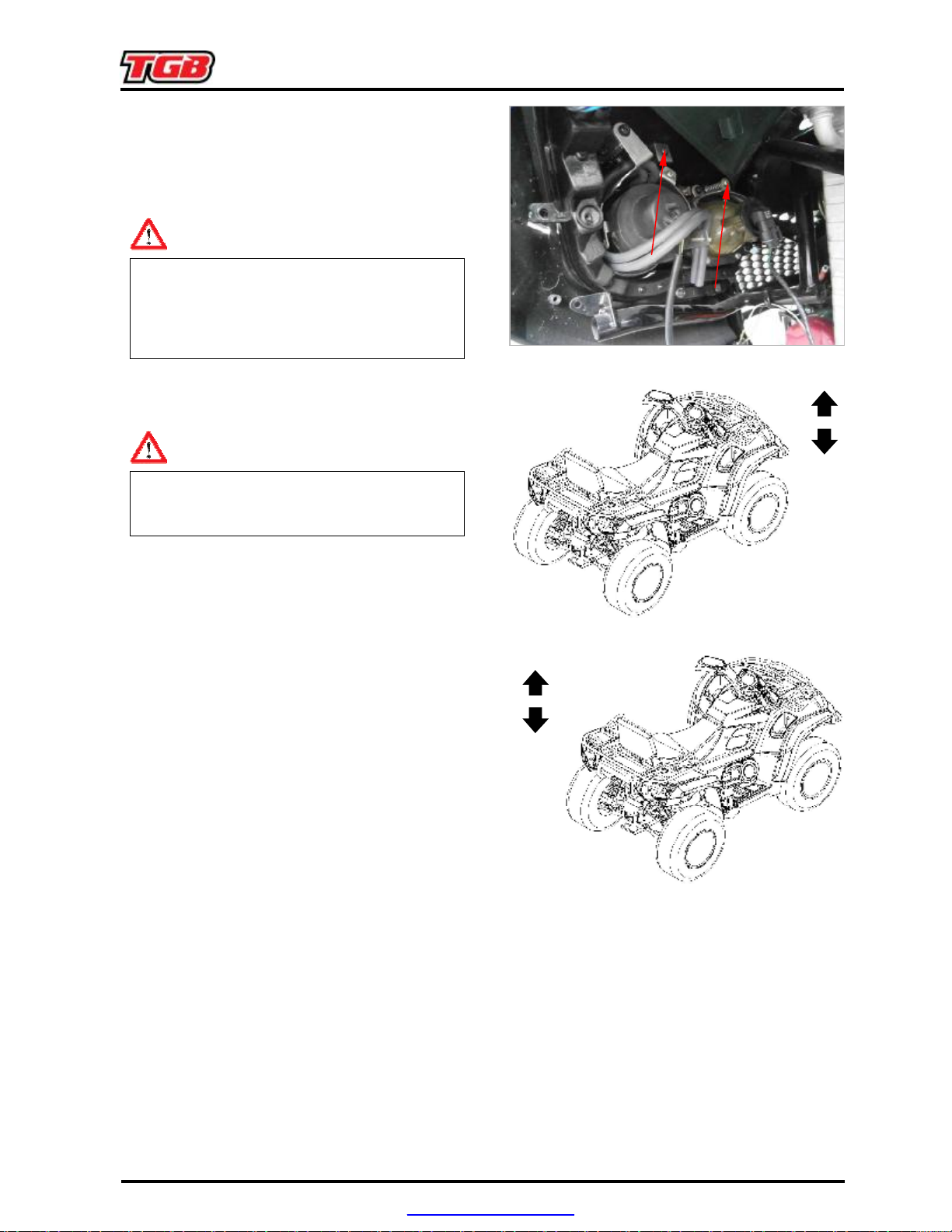
2. MAINTENANCE INFORMATION
Press down the front cushion for several times to
Headlight Beam Distance
Turn on main switch.
Headlight beam adjustment.
Turn the headlight adjustment screw to adjust
headlight beam high.
Caution
●
To adjust the headlight beam follows related
regulations.
●
Improper headlight beam adjustment will
make in coming driver dazzled or insufficient
lighting.
Cushion
●
Do not ride the ATV with poor cushion.
●
Looseness, wear or damage cushion will
make poor stability and drive-ability.
Warning
Front cushion
check it operation.
Check if it is damage
Replace relative parts if damage found.
Tighten all nuts and bolts.
Rear Cushion
Press down the rear cushion for several times to
check it operation.
Check if it is damage
Replace relative parts if damage found.
PDF created with pdfFactory Pro trial version www.pdffactory.com
2. MAINTENANCE INFORMATION
Check all wires and cables if they are interfered
handle can be operated in vertical direction, then
Check if tire surface is ticked with nails, stones or
central surface. Replace the tire if the depth is not
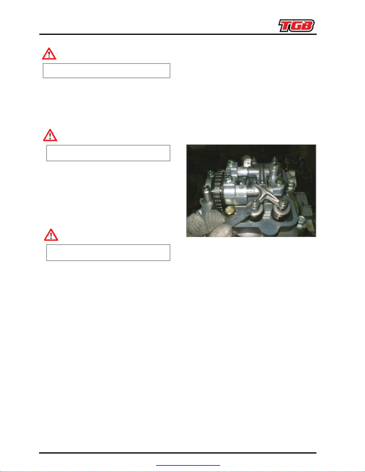
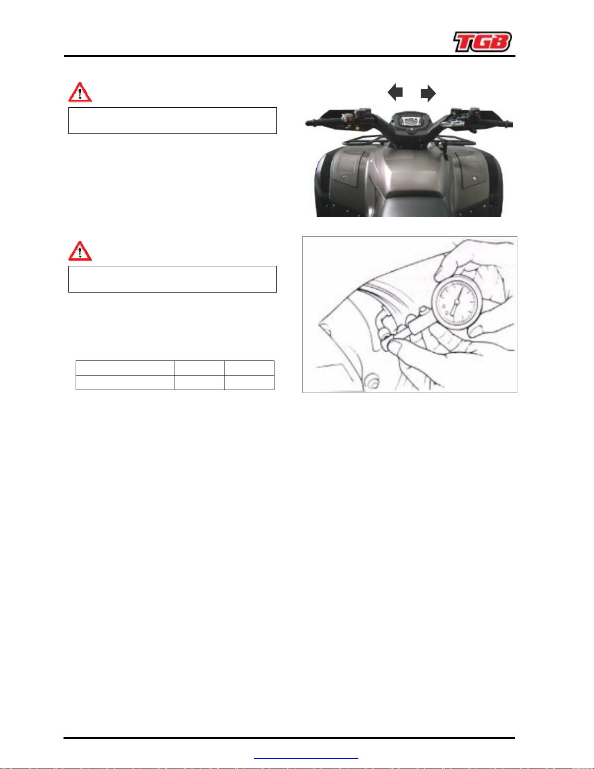
Steering Handle
Caution
with the rotation of steering handle bar.
Lift the front wheel out of ground.
Turn handle from right to left alternative and
check if turning is smoothly.
If handle turning is uneven and bending, or the
check the handle top bearing.
Wheel/Tire
Caution
Tire pressure check should be done as cold
engine.
other materials.
Appointed tire pressure
Tire size Front Tire Rear Tire
Tire pressure as cold 7
psi
7
psi
Check if front and rear tires’ pressure is in
normal. Measure tire thread depth from tire
come with following specification:
Front tire: 1.5 mm
Rear tire: 2.0 mm
Nuts, Bolts Tightness
Perform periodical maintenance in accord with
the Periodical Maintenance Schedule
Check if all bolts and nuts on the frame are
tightened securely.
Check all fixing pins, snap rings, hose clamp,
and wire holders for security.
PDF created with pdfFactory Pro trial version www.pdffactory.com

2. MAINTENANCE INFORMATION
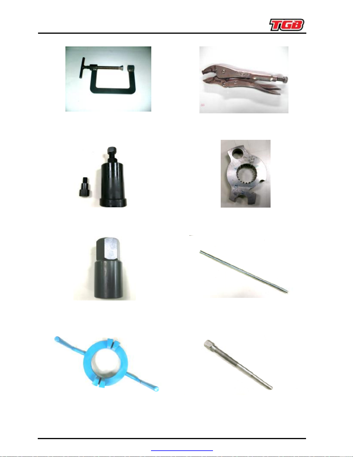
Special Tools List
PARTS NO. : 440649
PARTS NAME : EXTENSION PULLER / REMOVER
PARTS NO. : 440651
PARTS NAME : BEARING(924384) REMOVER φ15
PARTS NO. : 440650
PARTS NAME : BUSHING(924739) REMOVER
PARTS NO. : 440652
PARTS NAME : BEARING(924384) REMOVER
φ20
PARTS NO. : 440653
PARTS NAME : BEARING(924384) REMOVER φ45
PARTS NO. : 552303
PARTS NAME : PISTON & ROD CONNECTING
HOLDER
PARTS NO. : 440656
PARTS NAME : L CRANK CASE OIL SEAL
REMOVER
PARTS NO. : 440662
PARTS NAME : CYLINDER HEAD VALVE GAP
ADJUSTER
PDF created with pdfFactory Pro trial version www.pdffactory.com
2. MAINTENANCE INFORMATION
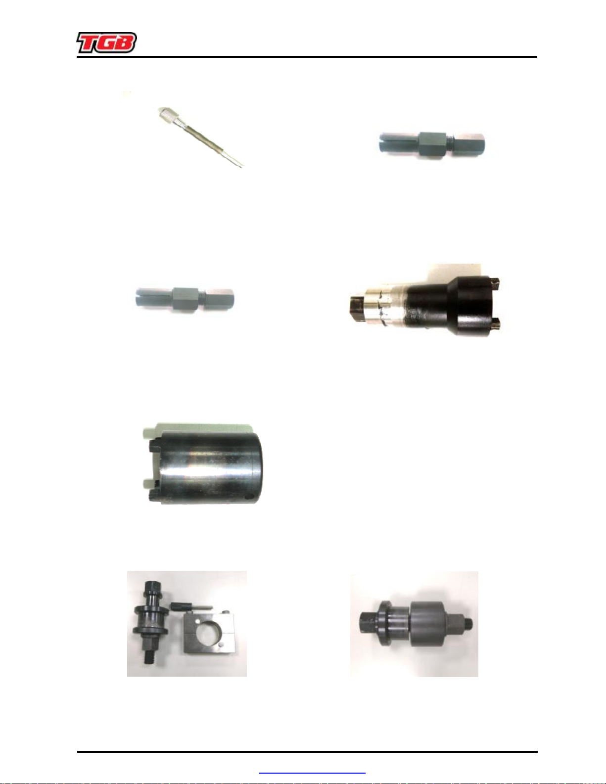
PARTS NO. : 440667
PARTS NAME : CYLINDER HEAD VALVE AND
SPRING INSTALLER/REMOVER
PARTS NO. : 560001
PARTS NAME : FLYWHEELREMOVER
PARTS NO. : 560003
PARTS NAME : RIGHT CRANKCASE MECHNICAL
SEAL INSTALLER/REMOVER
PARTS NO. : 560005
PARTS NAME : DRIVEN PULLEY FIXING TOOL
PARTS NO. : 440671
PARTS NAME : WET CLUTCH SCREW NUT
FIXER
PARTS NO. : 560002
PARTS NAME : FLYWHEEL INSTALLER
PARTS NO. : 560004
PARTS NAME : DRIVE PULLEY FIXING ROD
PARTS NO. : 560006
PARTS NAME : DRIVE PULLEY REMOVER
PDF created with pdfFactory Pro trial version www.pdffactory.com
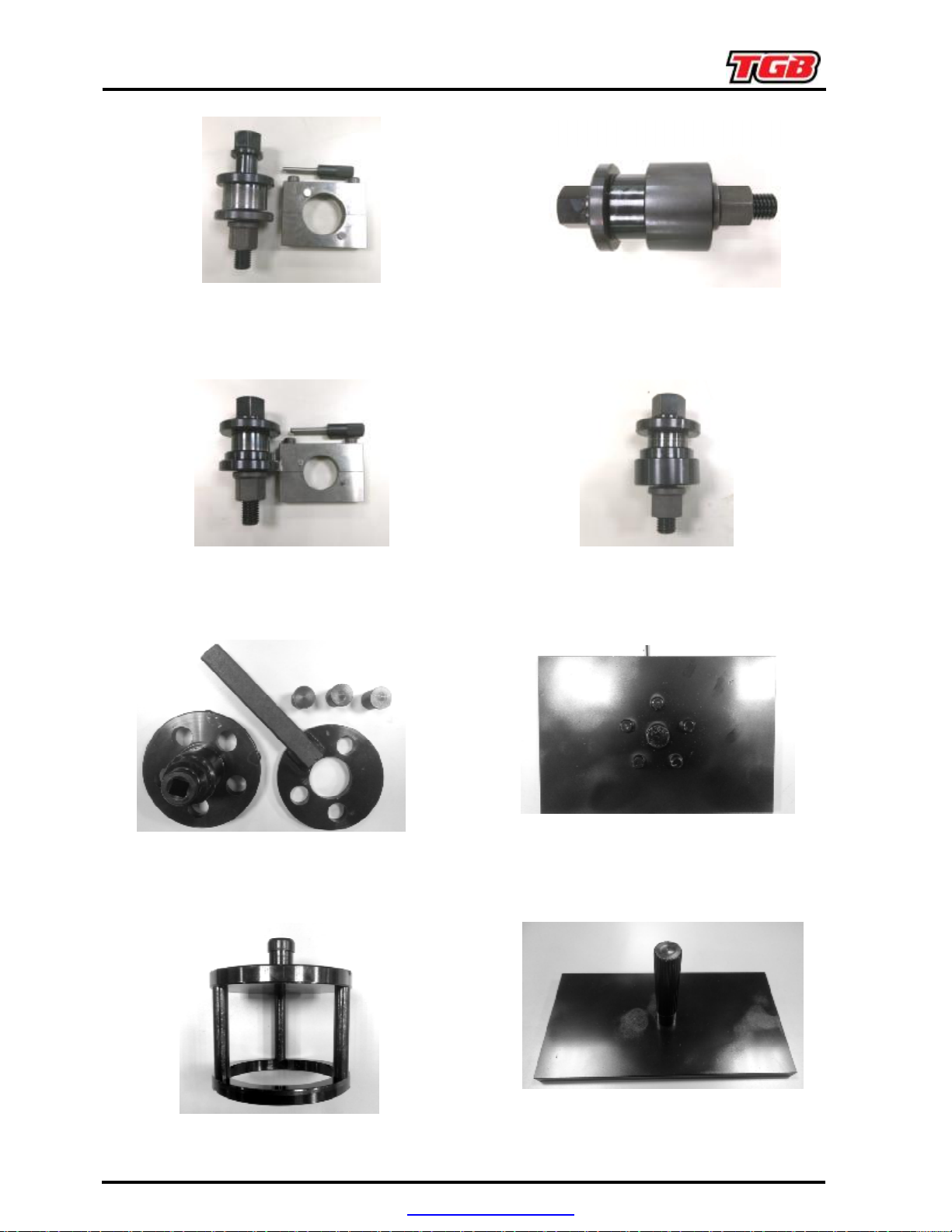
PARTS NO. : 560007
PARTS NAME : DRIVEN PULLEY EXTEND TOOL
FOR REMOVE BELT
PARTS NO. : 560009
PARTS NAME : DEAR DIFF. NEEDLE BEARING
REMOVER (W/ 440649 Ø20 mm)
PARTS NO. : 552312
PARTS NAME : EPS STEERING BEARING SEAT
SOCKET
PARTS NO. : 560011
PARTS NAME : PLAIN BEARING INSTALLER
(LEFT CRANKCASE)
2. MAINTENANCE INFORMATION
PARTS NO. : 560008
PARTS NAME : BEARING REMOVER (W/
440649 Ø20 mm)
PARTS NO. : 560010
PARTS NAME : REAR DIFF. BEARING SPACER
INSTALLER
PARTS NO. : 560012
PARTS NAME : PLAIN BEARING REMOVER
(LEFT CRANKCASE
PDF created with pdfFactory Pro trial version www.pdffactory.com
2. MAINTENANCE INFORMATION
PARTS NO. : 560013
PARTS NAME : PLAIN BEARING INSTALLER
(RIGHT CRANKCASE)
PARTS NO. : 560015
PARTS NAME : CRANKCASE COVER LH
PLAIN BEARING INSTALLER
(LEFT CRANKCASE)
PARTS NO. : 560017
PARTS NAME : GOVERNOR CUP
INSTALLER/REMOVER KIT
(DRIVE PULLEY)
PARTS NO. : 560019
PARTS NAME : HAFT SHEAVE PRESSING TOOL
PARTS NO. : 560014
PARTS NAME : PLAIN BEARING REMOVER
(RIGHT CRANKCASE
PARTS NO. : 560016
PARTS NAME : CRANKCASE COVER LH
PLAIN BEARING REMOVER
(LEFT CRANKCASE
PARTS NO. : 560018
PARTS NAME : DRIVE PULLEY FIXING SEAT
FOR INSTALL AND REMOVE
PARTS NO. : 560020
PARTS NAME : DRIVEN PULLEY FIXING SEAT
FOR INSTALL AND REMOVE
PDF created with pdfFactory Pro trial version www.pdffactory.com
Precautions in Operation
General Information
This chapter contains maintenance operation
for the engine oil pump and gear oil replacement.
Specifications
Engine oil quantity
Overhaul: 2300 c.c.
Filter change: 1800 c.c.
3.LUBRICATION SYSTEM
Change: 2000 c.c.
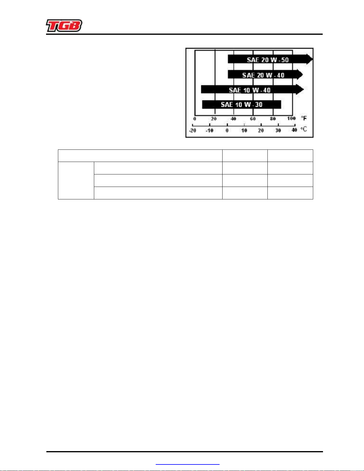
Oil viscosity SAE 10W-40
Oil pump
Torque value
Torque value oil filter cover 1.2 kgf-m
Engine oil drain bolt
Troubleshooting
Low engine oil level
●
Oil leaking
●
Valve guide or seat worn out
●
Piston ring worn out
● Camshaft worn out
Items
Inner rotor clearance
Clearance between outer rotor and body
Clearance between rotor side and body
2
.4 kgf-m
Standard (mm) Limit (mm)
0.15~0.20
0.15
0.20
0.04~0.09
0.25
0.12
● Camshaft main bearing worn out
Low oil pressure
●
Low engine oil level
●
Clogged in oil strainer, circuits or pipe, oil radiator gasket
●
Oil pump damage
● Oil pressure valve, oil filter
Dirty oil
●
No oil change in periodical
●
Cylinder head gasket damage
●
Piston ring worn out
● Camshaft worn out
● Camshaft main bearing worn out
PDF created with pdfFactory Pro trial version www.pdffactory.com

3.LUBRICATION SYSTEM
Engine oil can be very hot. Wait until engine
Oil condition gives information about the
gives an indication of failure inside the engine.
Oil Level Verification
NOTE:
wrong oil level may be indicated.
Strictly follow this procedure, otherwise
▪ Ensure vehicle is on a level surface.
▪ Start engine and let idle for a few minutes.
▪ Stop engine, wait a few minutes to allow oil to
flow down to crankcase then check oil level.
▪ Fully screw in dipstick to check oil level.
▪ Remove dipstick and read the oil level.
▪ Oil level must be between minimum and
maximum marks on dipstick.
▪ Refill oil as necessary. Do not overfill.
▪ Reinstall dipstick.
Oil Filter Change
▪ Ensure the vehicle is on a level surface.
▪ Oil and oil filter must be replaced at the same
time. Oil change and oil filter replacement
should be done with a warm engine.
Engine Type
Upper Level
Low Level
WARNING
oil is warm
▪ Place a drain pan under the engine drain plug
area.
▪ Clean the drain plug area.
▪ Unscrew drain plug and discard the gasket
ring.
▪ Remove dipstick.
▪ Allow oil to drain completely from crankcase.
NOTE:
engine condition.
▪ clean the magnetic drain plug from metal
shavings and residue. Presence of debris
Check engine to correct the problem.
▪ Install a NEW gasket ring on drain plug.
TORQUE:
2
.4 kgf-m
PDF created with pdfFactory Pro trial version www.pdffactory.com
3.LUBRICATION SYSTEM
CAUTION
Never use the gasket ring a second time.
Always replace by a new one.
▪ Replace oil filter.
▪ Refill engine with recommended engine oil.
▪ Oil change capacity with filter: 2.0 L.
▪ After filling, check the oil level with dipstick.
▪ Run engine to ensure oil filter and drain plug
areas are not leaking.
▪ Dispose oil and filter as per your local
environmental regulation.
INSPECTION
ENGINE OIL PRESSURE
NOTE:
done with a warm engine 90℃ and the
recommended oil.
▪
▪
The engine oil pressure test should be
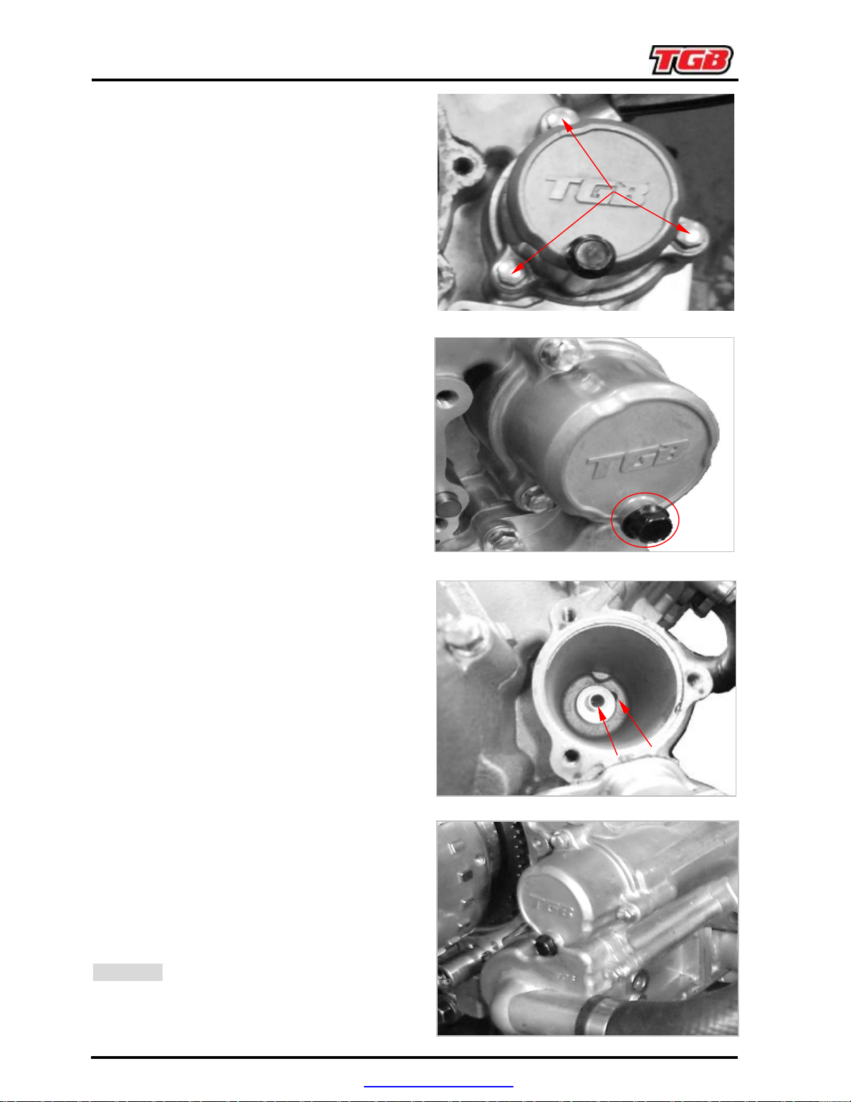
Remove the oil pressure switch.
PRESSURE GAUGE
Install
HOSE
.
and
ADAPTER
The engine oil pressure should be within the
following values.
OIL
PRESSURE
MINIMAL 10 psi 39 psi
NORMIAL
1250 RPM 6000 RPM
22 psi
46 psi
MAXIMAL
36 psi 70 psi
PDF created with pdfFactory Pro trial version www.pdffactory.com
3.LUBRICATION SYSTEM
▪
If the engine oil pressure is out of
specifications, check the points described in
troubleshooting section.
▪ Removal oil pressure gauge and adapter
hose.
NOTE:
pressure gauge, use the disconnect tool.
To remove adapter hose from oil
▪ Reinstall the oil pressure switch.
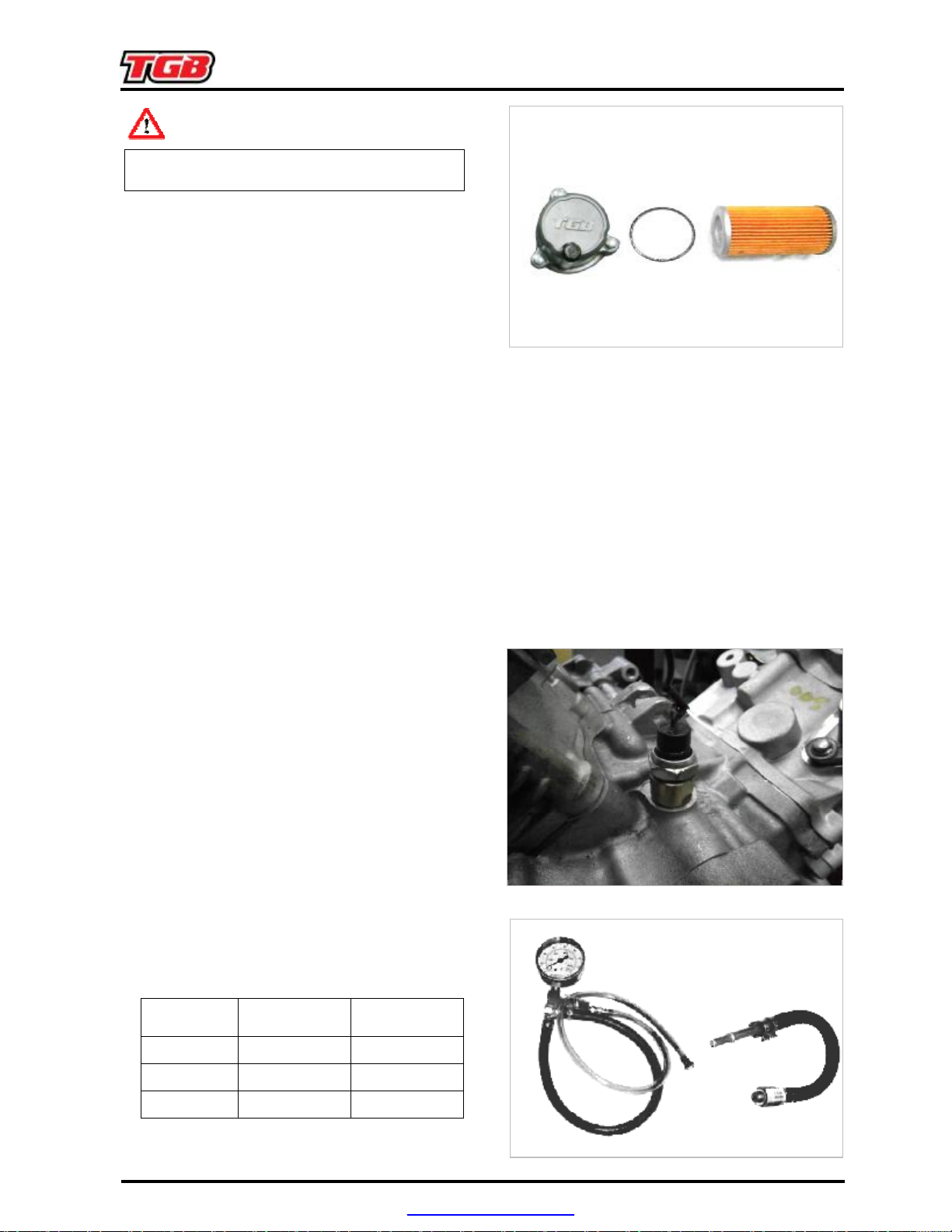
OIL FILTER
Oil Filter Removal
▪
Remove oil filter drain screw and washer.
▪
Drain out the oil inside the filter housing
▪
Remove three retaining screws and cover.
▪
Remove oil filter.
Oil Filter Inspection
Check and clean the oil filter inlet and outlet
area for dirt and other contaminations.
Oil Filter Installation
▪ Install a new O-ring on oil filter.
▪ Install the filter into the cover.
▪ Apply engine oil on O-ring and grease on the
end of filter.
▪ Install the cover on the engine.
TORQUE:
1.2
kgf-m
PDF created with pdfFactory Pro trial version www.pdffactory.com
3.LUBRICATION SYSTEM
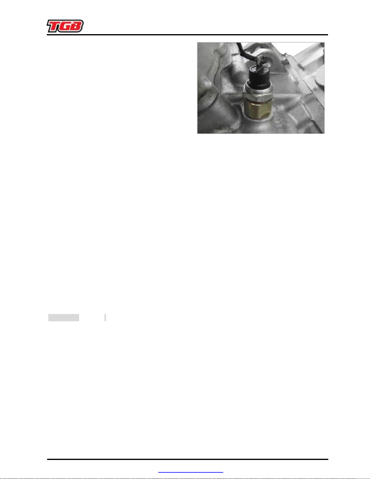
switch
Install oil pressure switch with LOCTITE
OIL PRESSURE SWITCH
Oil Pressure Switch Activation
▪ Oil pressure switch works when engine oil
pressure is between 20 and 40 kPa.
▪ To check the function of the oil pressure
switch, an oil pressure test has to be
performed. If the engine oil pressure is good,
check the resistance of the oil pressure
while engine is off and while engine is running.
Oil Pressure Switch Test
▪ Disconnect the connector from oil pressure
switch.
▪ Use multimeter to check the continuity.
▪ Replace the oil pressure switch if necessary.
▪ If OK, check the continuity of the wiring
harness.
Oil Pressure Switch Removal
Unplug then unscrew the oil pressure switch.
Oil Pressure Switch Installation
NOTE:
243.
TORQUE:
ENGINE OIL PRESSURE VALVE
The oil pressure valve is located on the engine
magneto side (inside magneto cover).
NOTE:
when oil pressure exceeds 70 psi.
1.7
kgf-m
.
The oil pressure valve system works
PDF created with pdfFactory Pro trial version www.pdffactory.com
3.LUBRICATION SYSTEM
Clean bore and thread in the magneto housing
Removal
▪ Remove the bolts and the ACG cover.
▪ Pull out the oil pressure valve and washer.
Inspection
▪ Inspect pressure valve housing, O-ring and
valve for scoring or other damages.
▪
from metal shavings and other contamination.
Installation
For installation, reverse the removal procedure.
NOTE: At installation, always replace the
gasket ring.
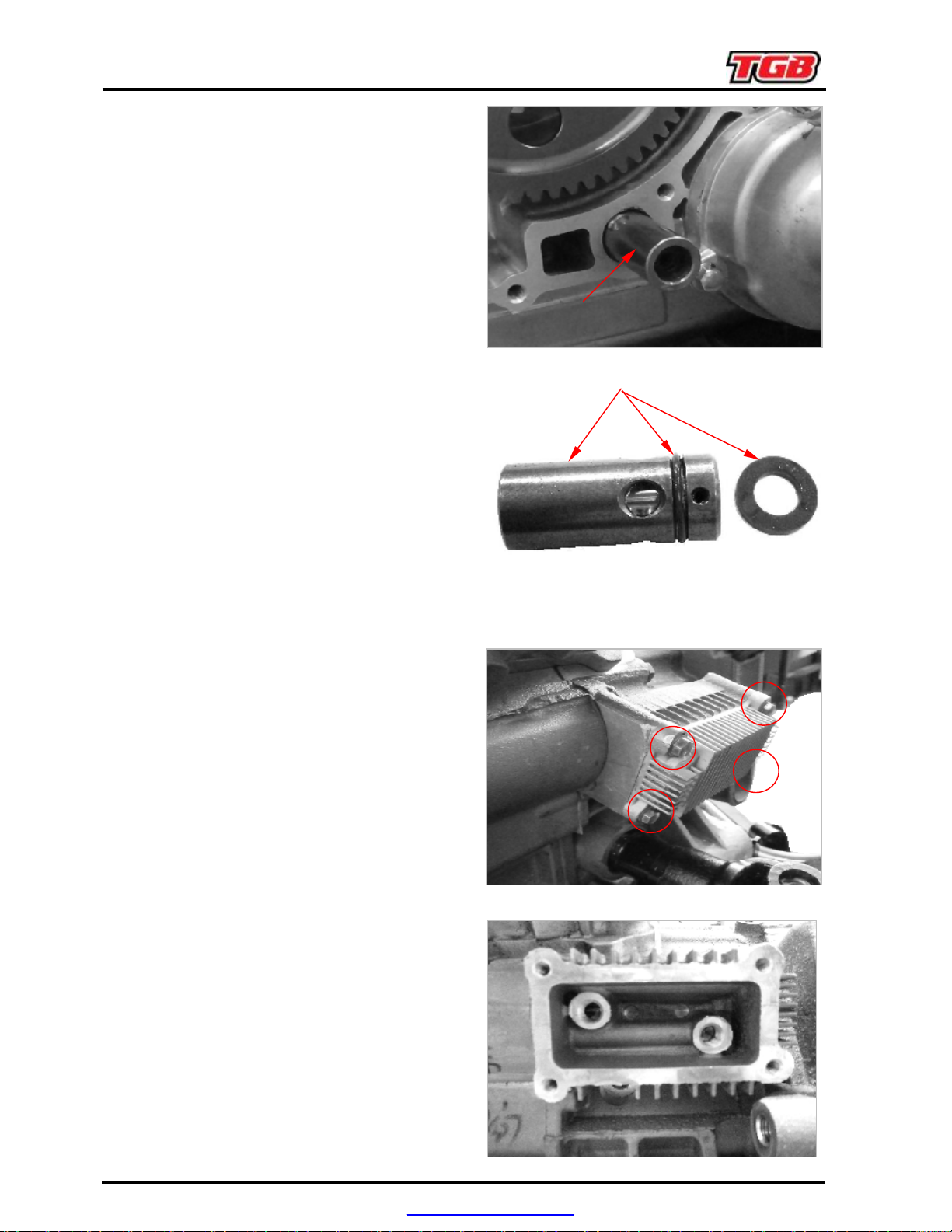
OIL RADIATOR
Oil Radiator Removal
▪ Drain engine oil.
▪ Drain coolant.
▪ Remove oil radiator cap retaining bolts.
▪ Place rags or towels under oil cooler to catch
remaining oil and coolant.
▪ Remove oil radiator and discard gasket.
Oil Radiator Inspection
▪ Check oil radiator for cracks or other damage.
▪ Replace if necessary.
Oil Radiator Installation
▪ For installation, reverse the removal
procedure.
▪ Wipe off any oil and coolant spillage.
▪ Install a new gasket.
▪ Refill engine oil with recommended oil and at
the proper oil level.
▪ Refill and bleeding cooling system.
PDF created with pdfFactory Pro trial version www.pdffactory.com
3.LUBRICATION SYSTEM
is located on the engine CVT side
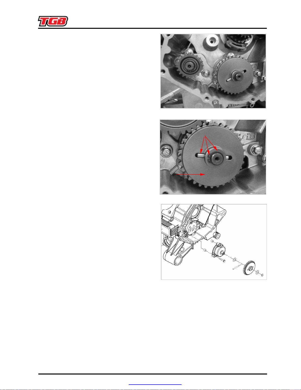
OIL PUMP
The oil pump
(behind cover).
Removal
▪ Drain engine oil.
▪ Remove parts to access the CVT cover.
▪ Remove the CVT cover.
▪ Remove CVT assembly.
▪ Remove crankcase cover LH.
▪ Remove:
- retaining ring.
- oil pump gear.
- needle pin
- thrust washer.
- oil pump flange bolts.
- oil pump cover screws and pull oil pump
cover.
- oil pump shaft with inner rotor and outer
rotor.
Inspection
▪ Inspect oil pump for marks or other damages.
▪ Check for scratches din crankcase between
outer rotor and oil pump bore. If so, replace
damaged parts.
▪ Check inner rotor for corrosion pinholes or
other damages. If so, replace oil pump shaft
assembly.
PDF created with pdfFactory Pro trial version www.pdffactory.com
3.LUBRICATION SYSTEM
If clearance between outer rotor and its bore in
Difference between measurements should not
exceed 0.2 mm. If so, replace the complete oil
▪ Using a feeler gauge, measure the clearance
of inner and outer rotors as shown.
▪ If clearance of inner and outer rotors exceeds
the tolerance, replace oil pump shaft
assembly. Ensure to also check oil pump
cover. If damaged, replace the complete oil
pump assembly.
▪
crankcase exceeds the tolerance, replace the
complete oil pump assembly and/or the
crankcase.
▪ Using a depth gauge, measure the axial
clearance of the oil pump as shown.
▪
pump assembly.
NOTE:
pump shaft assembly increases, the oil
pressure decreases.
When the axial clearance of the oil
Installation
For installation, reverse the removal procedure.
NOTE:
marked. When installing, make sure both
markings are on the upper side.
After reinstallation of remaining parts, check for
smooth operation of the oil pump assembly.
The outer rotor and inner rotor are
Oil Pump Final Test
After engine is completely reassembled, start
engine and make sure oil pressure is within
specifications.
PDF created with pdfFactory Pro trial version www.pdffactory.com
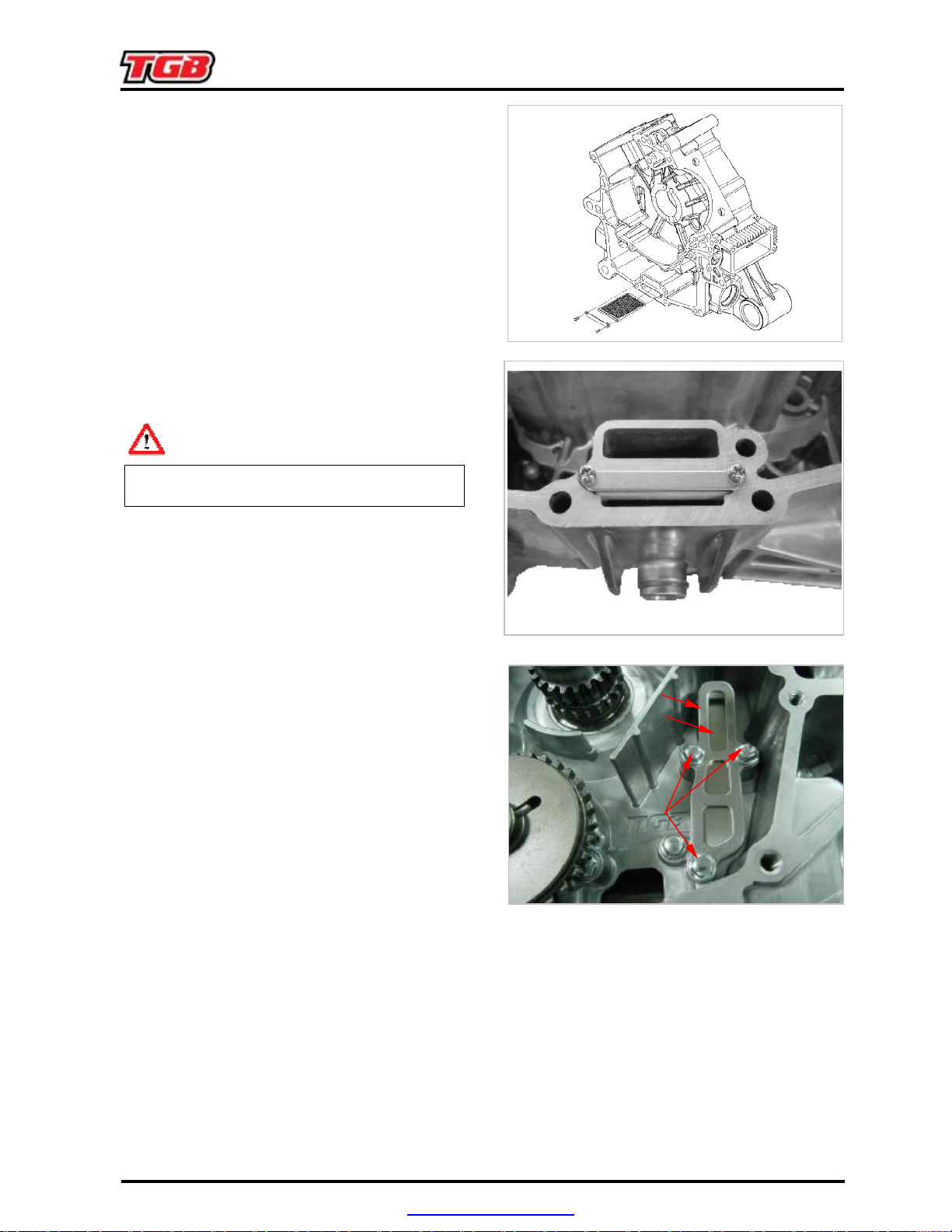
3.LUBRICATION SYSTEM
The engine oil strainer is located between both
cause a rash break out and injure your eyes.
①②③
ENGINE OIL STRAINER
▪
crankcase halves.
▪ Usually the strainer no needs to clean.
▪ During engine over hall, it will clean after
separate the crankcase half.
▪ Remove the retaining bolts and pull the oil
strainer out.
Cleaning and Inspection
▪ Clean engine oil strainer with a part cleaner
then use airgun to dry it.
WARNING
Always wear eye protector. Chemicals can
▪ Check engine oil strainer for cracks or other
damage. Replace if damaged.
Installation
For installation, reverse the removal procedure.
REED VALVE
The engine is equipped with reed valve, which
prevents accumulation of large oil quantities in
the crankcase. The reed valve is fitted into the
crankcase.
Valve Removal
Remove
- Reed valve three retaining bolts.
- Stopper plate.
- Reed valve.
Valve Inspection
Check reed valve for cracks or other damage.
NOTE:
Replace reed valve if damaged.
Valve installation
For installation, reverse the removal procedure.
PDF created with pdfFactory Pro trial version www.pdffactory.com
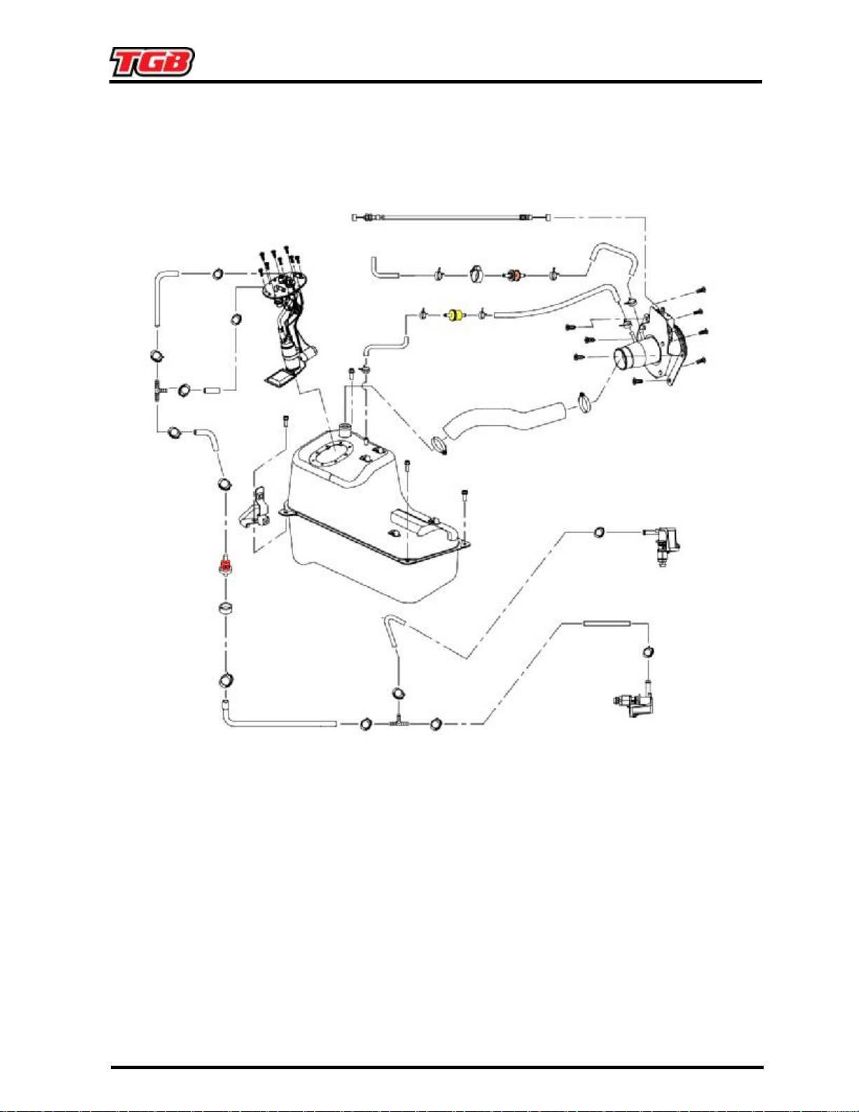
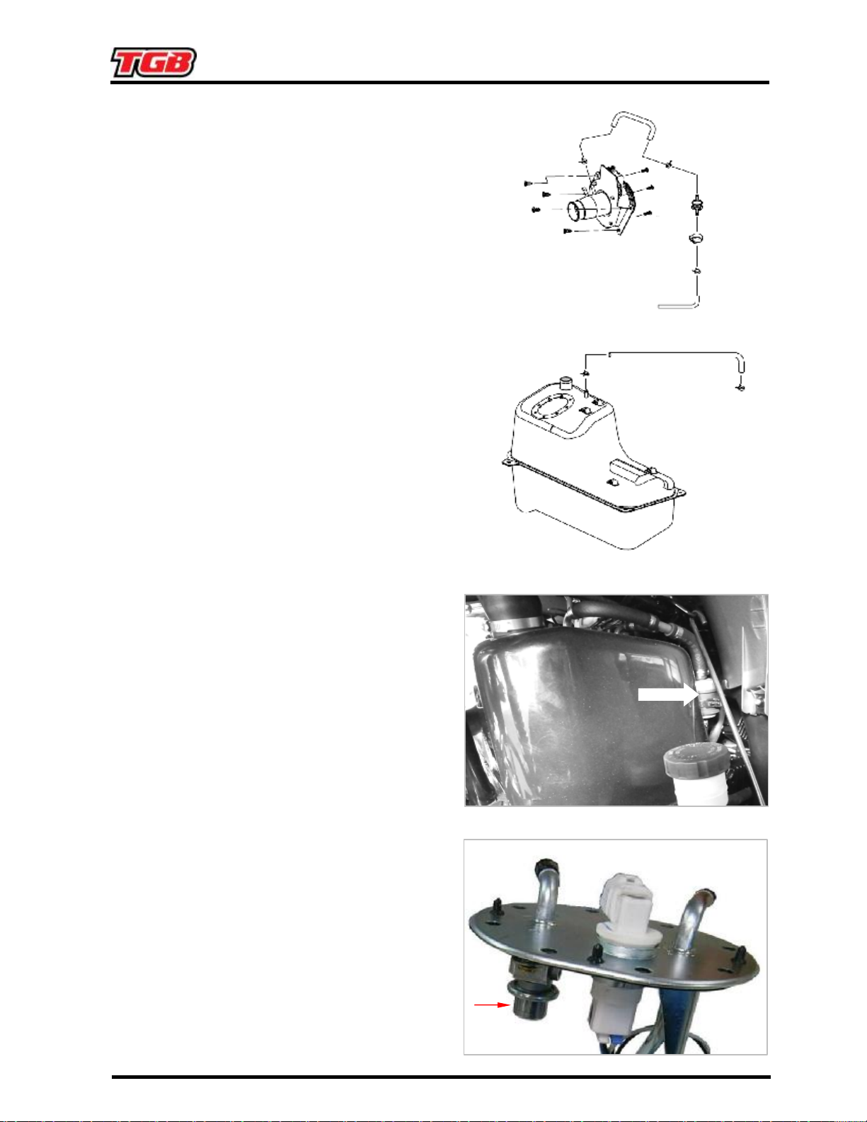
FUEL TANK AND FUEL PUMP
4-1. FUEL SYSTEM
4-1. FUEL SYSTEM
FUEL TANK AND FUEL PUMP
GENERAL
WARNING
Fuel is flammable and explosive under certain conditions. Ensure work area is well
ventilated. Do not smoke or allow open flames or sparks in the vicinity.
WARNING
Always disconnect battery prior to working on the fuel system.
WARNING
Torque wrench tightening specifications must strictly be adhered to.
Locking devices (e.g.: locking tabs, elastic stop nuts, self-locking fasteners, cotter pin, etc.)
must be replaced.
WARNING
Always proceed with care and use appropriate safety equipment when working on
pressurized fuel system. Wear safety glasses.
WARNING
Do not allow fuel to spill on hot engine parts and/or on electrical connectors.
▪ When the repair is completed, ensure that all hoses are connected and secured.
▪ Fuel lines remain under pressure at all times.
▪ Proceed with care when removing/installing high pressures test equipment.
▪ Disconnect the fuel pump electrical connector to disable fuel pump and crank engine to release fuel
pressure prior to disconnecting any fuel hose.
▪ Cover the fuel hose connections with an absorbent shop rag and carefully disconnect them to
minimize spilling.
▪ Wipe off any fuel spillage.
▪ Hoses, cables or locking ties removed during a procedure must be reinstalled as per factory
standards.
4-1. FUEL SYSTEM
out through the inlet of the vent system should
SYSTEM DESCRIPTION
Fuel Tank Vent System
▪ The fuel tank is equipped with a vent system
that ensures the fuel tank remains at ambient
pressure.
▪ Air can enter the fuel tank at all times through
the fuel tank vent valve. This prevents
negative pressure within the fuel tank, which
could cause fuel starvation.
▪ The vent valve also prevents fuel from flowing
the vehicle be overturned.
Fuel Pump Assembly
▪ The fuel pump assembly is inserted in the fuel
tank.
▪ It provides fuel delivery for EFI system and
encompasses the following components:
- Electric fuel pump.
- Fuel pre-filter.
- Fuel pressure regulator.
- Fuel level sender.
Fuel Filters
▪ The fuel filter is located on the right of the fuel
tank, which connected fuel line before go into
the fuel injector nozzle.
▪ For replace, please using Oetiker pliers to
remove the clamp..
Fuel Pump Pressure Regulator
▪ The fuel pressure is integral to the fuel pump
assembly. The pressure regulator maintains
proper fuel pressure for the EFI system.
 Loading...