

TGB blade 300 Service Manual

BLADE 250/300
SERVICE MANUAL
PDF created with pdfFactory Pro trial version www.pdffactory.com

Homepag
e Contents
FORWARD
This service manual contains the technical data of each component inspection and
repair for the
BLADE
250/300 ATV. The manual is shown with
illustrations and focused on “Service Procedures”, “Operation Key Points”, and
“Inspection Adjustment” so that provides technician with service guidelines.
If the style and construction of the ATV,
BLADE
250/300, are different from that
of the photos, pictures shown in this manual, the actual vehicle shall prevail.
Specifications are subject to change without notice.
Service Department
TAIWAN GOLDEN BEE CO., LTD.
PDF created with pdfFactory Pro trial version www.pdffactory.com
Homepage Contents
HOW TO USE THIS MANUAL
This service manual describes basic information of different system parts and
system inspection & service for
please refer to the manual contents in detailed for the model you serviced in
inspection and adjustment.
The first chapter covers general information and trouble diagnosis.
The second chapter covers service maintenance information and special tools
manual.
The third to the 11th chapters cover engine and driving systems.
The 12th chapter is cooling system.
The 13th to the 16th chapter is contained the parts set of assembly frame body.
The 17th chapter is electrical equipment.
The 18th chapter is wiring diagram.
Please see index of content for quick having the special parts and system
information.
BLADE
250/300 ATV. In addition,
PDF created with pdfFactory Pro trial version www.pdffactory.com
Homepage
CONTENTS
Page Content Index
1-1 ~ 1-19
2-1 ~ 2-14
3-1 ~ 3-8
4-1 ~ 4-12
5-1 ~ 5-6
6-1 ~ 6-16
7-1 ~ 7-8
8-1 ~ 8-14
9-1 ~ 9-12
10-1 ~ 10-10 ALTERNATOR
11-1 ~ 11-8
13-1 ~ 13-9
14-1 ~ 14-14 FRONT BRAKE AND FRONT WHEEL
15-1 ~ 15-10 STEERING/FRONT SUSPENSION
16-1 ~ 16-18 REAR BRAKE/REAR WHEEL/REAR CUSHION
17-1 ~ 17-22 ELECTRICAL EQUIPMENT
18-1 ~ 18-2
GENERAL INFORMATION
SERVICE MAINTENANCE INFORMATION
LUBRICATION SYSTEM
FUEL SYSTEM
ENGINE REMOVAL
CYLINDER HEAD/VALVE
CYLINDER/PISTON
“V” TYPE BELT DRIVING SYSTEM/KICK-STARTER
FINAL DRIVING MECHANISM
CRANKSHAFT/ CRANKCASE
BODY COVER
ELECTRICAL DIAGRAM
1
2
3
4
5
6
7
8
9
10
11
13
14
15
16
17
18
PDF created with pdfFactory Pro trial version www.pdffactory.com
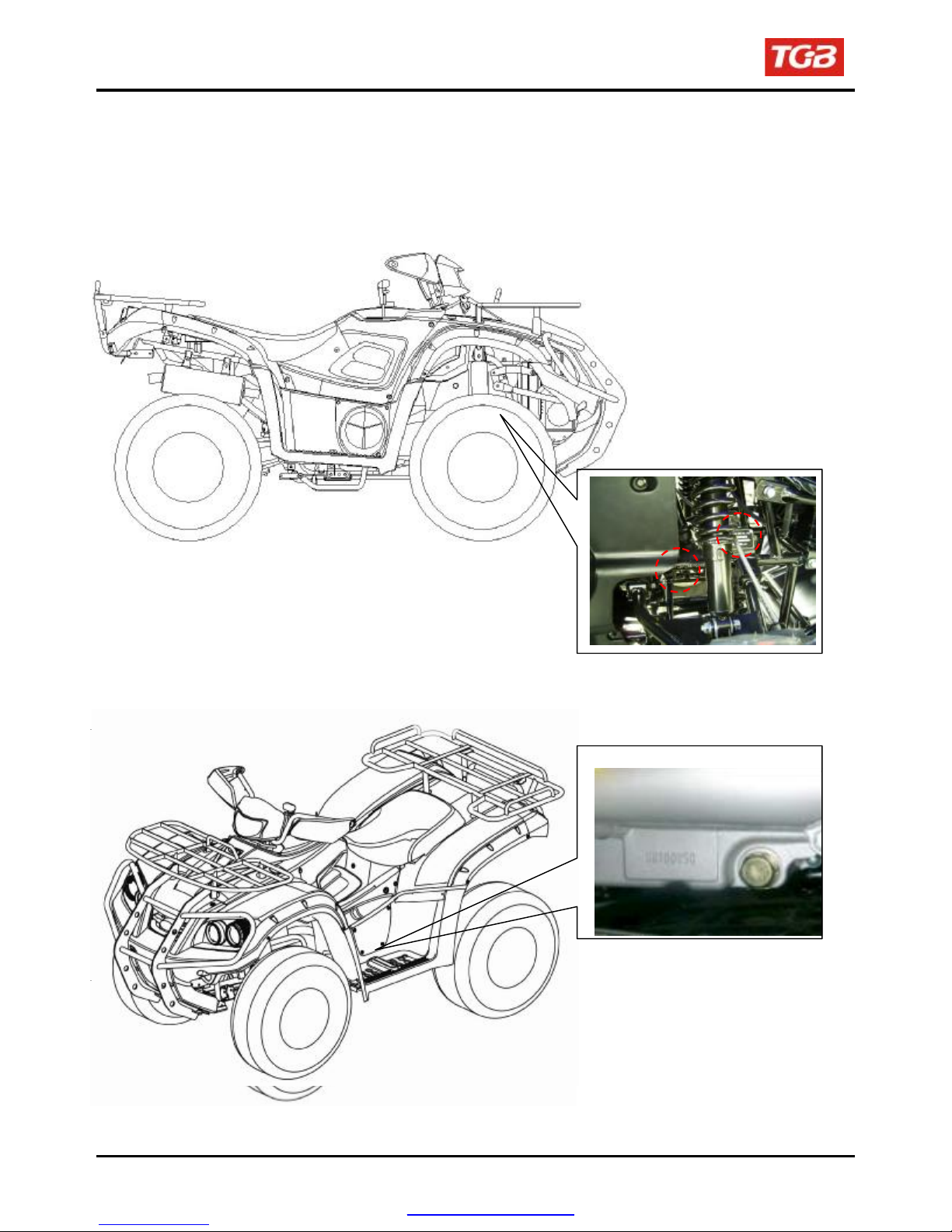
SERIAL NUMBER
Frame number
Home page
Contents
Engine number
PDF created with pdfFactory Pro trial version www.pdffactory.com
1. GENERAL INFORMATION
Homepage Contents
Symbols and Marks............................. 1-1
General Safety ..................................... 1-2
Service Precautions ............................ 1-3
Specifications ...................................... 1-9
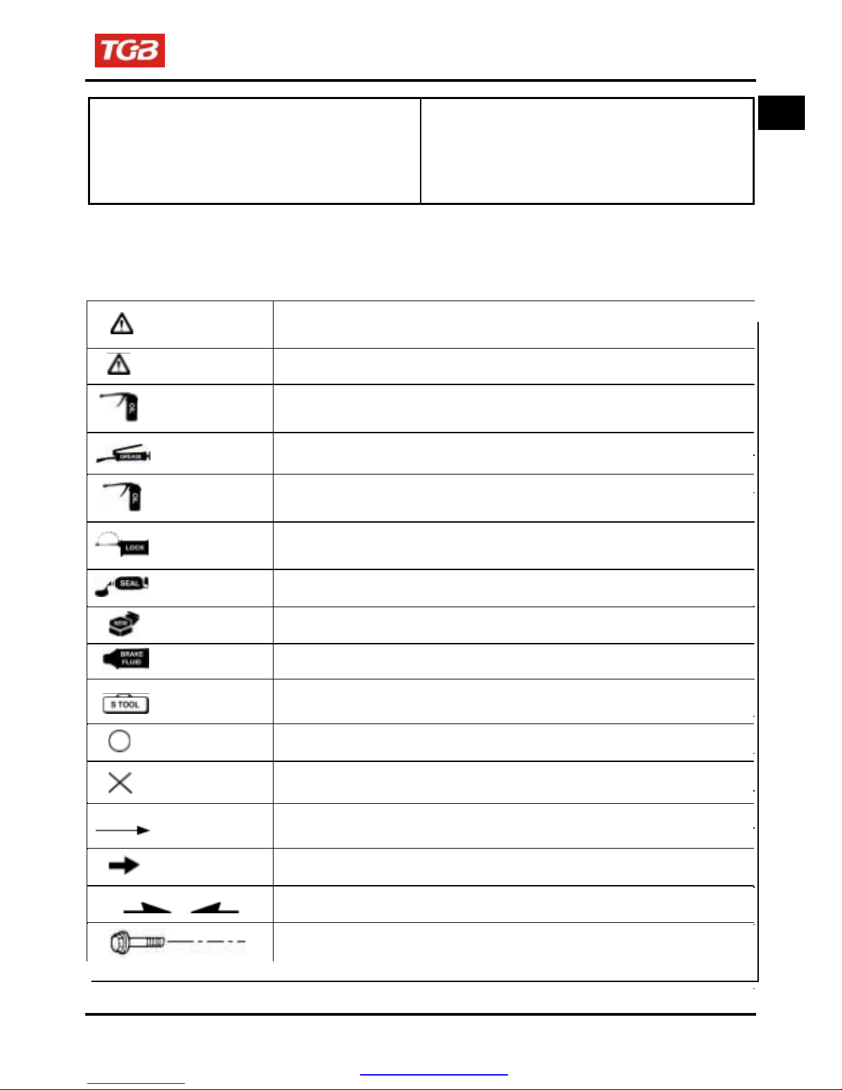
Symbols and Marks
Symbols and marks are used in this manual to indicate what and where the special service are needed, in
case supplemental information is procedures needed for these symbols and marks, explanations will be
added to the text instead of using the symbols or marks.
Warning
Caution
Engine oil
Locking sealant
Oil seal
Brake fluid
Grease
Gear oil
Renew
Means that serious injury or even death may result if procedures are not
followed.
Means that equipment damages may result if procedures are not followed.
Limits to use SAE 10W-30 API SG class oil. Warranty will not cover the
damage that caused by not apply with the limited engine oil.
(Recommended oil: KING MATE G-3 oil)
King Mate G-3 is recommended.
King Mate gear oil serials are recommended. (Bramax HYPOID GEAR OIL
# 140)
Apply sealant; medium strength sealant should be used unless otherwise
specified.
Apply with lubricant.。
Replace with a new part before installation.
Use recommended brake fluid DOT3 or WELLRUN brake fluid.
Special tools
Correct
Special tools
Meaning correct installation.
Wrong
Meaning wrong installation.
Specifications..................................... 1-10
Torque Values .................................... 1-11
Troubles Diagnosis............................ 1-13
Lubrication Points ............................. 1-18
1
Directions
PDF created with pdfFactory Pro trial version www.pdffactory.com
Indication
Indication of components.
Indicates position and operation directions
Components assembly directions each other.
Indicates where the bolt installation direction, --- means that bolt
cross through the component (invisibility)
1-1
1. GENERAL INFORMATION
To this chapter contents
General Safety
Carbon monoxide
If you must run your engine, ensure the place is
well ventilated. Never run your engine in a closed
area. Run your engine in an open area, if you have
to run your engine in a closed area, be sure to use
an extractor.
Caution
Exhaust contains toxic gas which may cause one
to lose consciousness and even result in death.
Gasoline
Gasoline is a low ignition point and explosive
material. Work in a well-ventilated place, no flame
or spark should be allowed in the work place or
where gasoline is being stored.
Caution
Gasoline is highly flammable, and may explode
under some conditions, keep it away from
children.
Used engine oil
Caution
Prolonged contact with used engine oil (or
transmission oil) may cause skin cancer although it
might not be verified.
We recommend that you wash your hands with
soap and water right after contacting. Keep the
used oil beyond reach of children.
Hot components
Caution
Components of the engine and exhaust system
can become extremely hot after engine running.
They remain very hot even after the engine has
been stopped for some time. When performing
service work on these parts, wear insulated
gloves and wait until cooling off.
1-2
Battery
Caution
‧
Battery emits explosive gases; flame is strictly
prohibited. Keeps the place well ventilated
when charging the battery.
‧
Battery contains sulfuric acid (electrolyte)
which can cause serious burns so be careful
do not be spray on your eyes or skin. If you
get battery acid on your skin, flush it off
immediately with water. If you get battery acid
in your eyes, flush it off immediately with water
and then go to hospital to see an
ophthalmologist.
‧
If you swallow it by mistake, drink a lot of
water or milk, and take some laxative such as
castor oil or vegetable oil and then go to see a
‧
doctor.
Keep electrolyte beyond reach of children.
Brake shoe
Do not use an air hose or a dry brush to clean
components of the brake system; use a vacuum
cleaner or the equivalent to avoid dust flying.
Caution
Inhaling brake shoe or pad ash may cause
disorders and cancer of the breathing system
Brake fluid
Caution
Spilling brake fluid on painted, plastic, or rubber
parts may cause damage to the parts. Place a
clean towel on the above-mentioned parts for
protection when servicing the brake system.
Keep the brake fluid beyond reach of children.
PDF created with pdfFactory Pro trial version www.pdffactory.com
To this chapter contents
Service Precautions
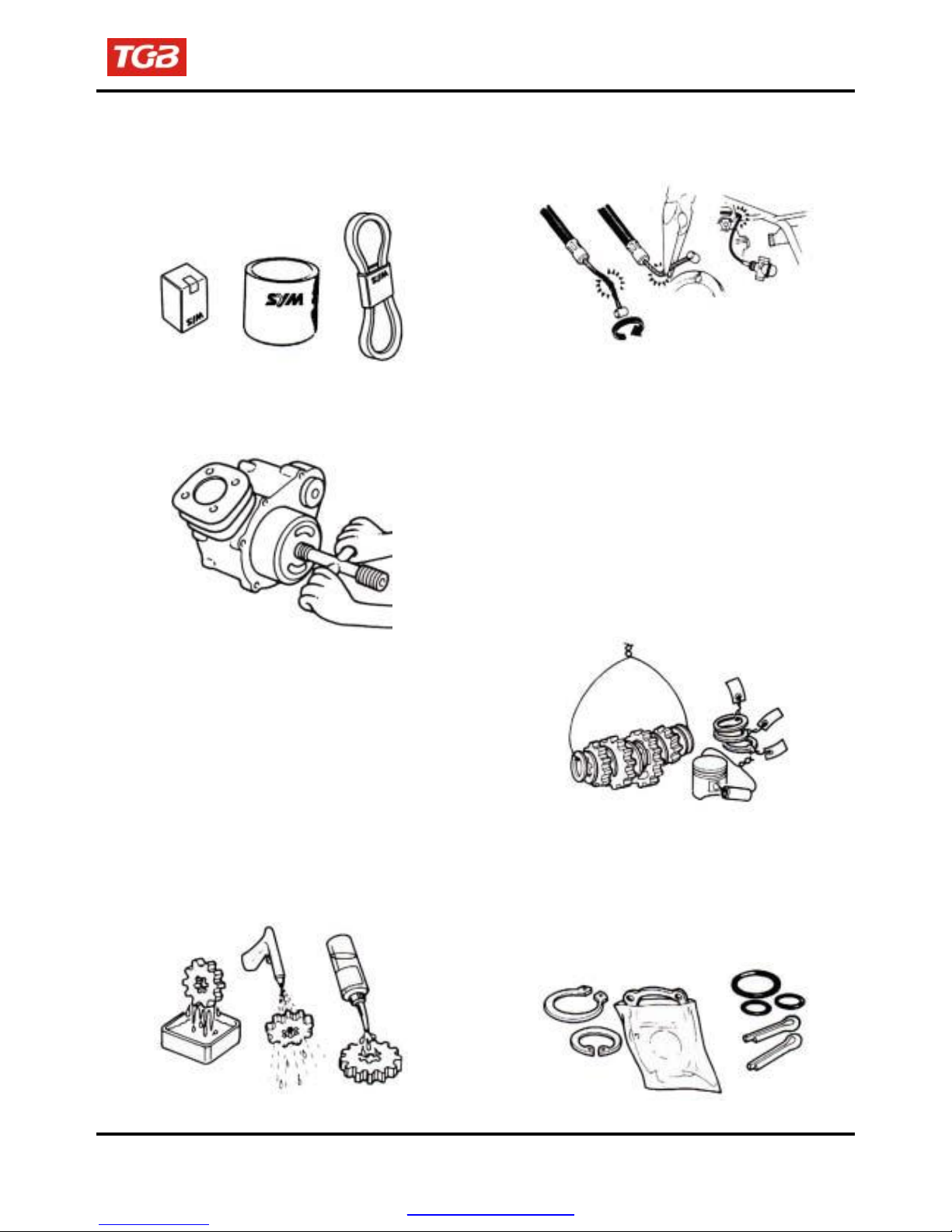
●
Always use with SANYANG genuine parts and
recommended oils. Using non-designed parts for
SANYANG ATV may damage the ATV.
●
Special tools are designed for remove and
install of components without damaging the
parts being worked on. Using wrong tools may
result in parts damaged.
●
When servicing this ATV, use only metric tools.
Metric bolts, nuts, and screws are not
interchangeable with the English system, using
wrong tools and fasteners may damage this
vehicle.
●
Clean the outside of the parts or the cover before
removing it from the ATV. Otherwise, dirt and
deposit accumulated on the part's surface may fall
into the engine, chassis, or brake system to cause
damage.
●
Wash and clean parts with high ignition point
solvent, and blow dry with compressed air. Pay
special attention to O-rings or oil seals because
most cleaning agents have an adverse effect on
them.
1. GENERAL INFORMATION
●
Never bend or twist a control cable to prevent
unsmooth control and premature worn out.
●
Rubber parts may become deteriorated when old,
and prone to be damaged by solvent and oil.
Check these parts before installation to make sure
that they are in good condition, replace if
necessary.
●
When loosening a component which has
different sized fasteners, operate with a
diagonal pattern and work from inside out.
Loosen the small fasteners first. If the bigger
ones are loosen first, small fasteners may
receive too much stress.
●
Store complex components such as
transmission parts in the proper assemble order
and tie them together with a wire for ease of
installation later.
●
Note the reassemble position of the important
components before disassembling them to
ensure they will be reassembled in correct
dimensions (depth, distance or position).
●
Components not to be reused should be
replaced when disassembled including gaskets
metal seal rings, O-rings, oil seals, snap rings,
and split pins.
PDF created with pdfFactory Pro trial version www.pdffactory.com
1-3
To this chapter contents
1. GENERAL INFORMATION
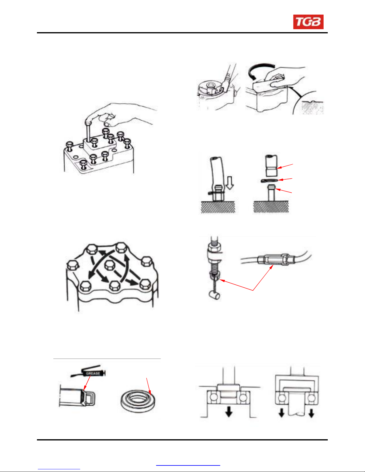
●
The length of bolts and screws for assemblies,
cover plates or boxes is different from one another,
be sure they are correctly installed. In case of
confusion, Insert the bolt into the hole to compare
its length with other bolts, if its length out side the
hole is the same with other bolts, it is a correct
bolt. Bolts for the same assembly should have the
same length.
●
Remove residues of the old gasket or sealant
before reinstallation, grind with a grindstone if
the contact surface has any damage.
●
Tighten assemblies with different dimension
fasteners as follows: Tighten all the fasteners
with fingers, then tighten the big ones with
special tool first diagonally from inside toward
outside, important components should be
tightened 2 to 3 times with appropriate
increments to avoid warp unless otherwise
indicated. Bolts and fasteners should be kept
clean and dry. Do not apply oil to the threads.
●
When oil seal is installed, fill the groove with
grease, install the oil seal with the name of the
manufacturer facing outside, and check the shaft
on which the oil seal is to be installed for
smoothness and for burrs that may damage the
oil seal.
Manufacturer's name
1-4
●
The ends of rubber hoses (for fuel, vacuum, or
coolant) should be pushed as far as they can go
to their connections so that there is enough room
below the enlarged ends for tightening the
clamps.
Groove
Clamp
Connector
●
Rubber and plastic boots should be properly
reinstalled to the original correct positions as
designed.
●
The tool should be pressed against two (inner
and outer) bearing races when removing a ball
bearing. Damage may result if the tool is pressed
against only one race (either inner race or outer
race). In this case, the bearing should be
replaced. To avoid damaging the bearing, use
equal force on both races.
Both of these examples can result in
bearing damage.
Boots
PDF created with pdfFactory Pro trial version www.pdffactory.com
To this chapter contents
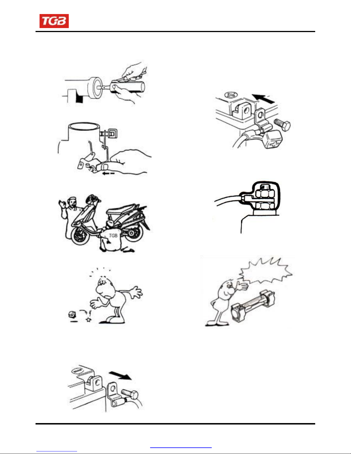
●
Lubricate the rotation face with specified
lubricant on the lubrication points before
assembling.
1. GENERAL INFORMATION
●
After service completed, make sure all
connection points is secured.
Battery positive (+) cable should be connected
firstly.
●
And the two posts of battery have to be greased
after connected the cables.
●
Check if positions and operation for installed
parts is in correct and properly.
●
Make sure service safety each other when
conducting by two persons.
●
Note that do not let parts fall down.
●
Before battery removal operation, it has to
remove the battery negative (-) cable firstly. Notre
tools like open-end wrench do not contact with
body to prevent from circuit short and create
spark.
●
Make sure that the battery post caps are
located in properly after the battery posts had
been serviced.
●
If fuse burned, it has to find out the cause and
solved it. And then replace with specified
capacity fuse.
Capacity
verification
1-5
PDF created with pdfFactory Pro trial version www.pdffactory.com
To this chapter c
ontents
1. GENERAL INFORMATION
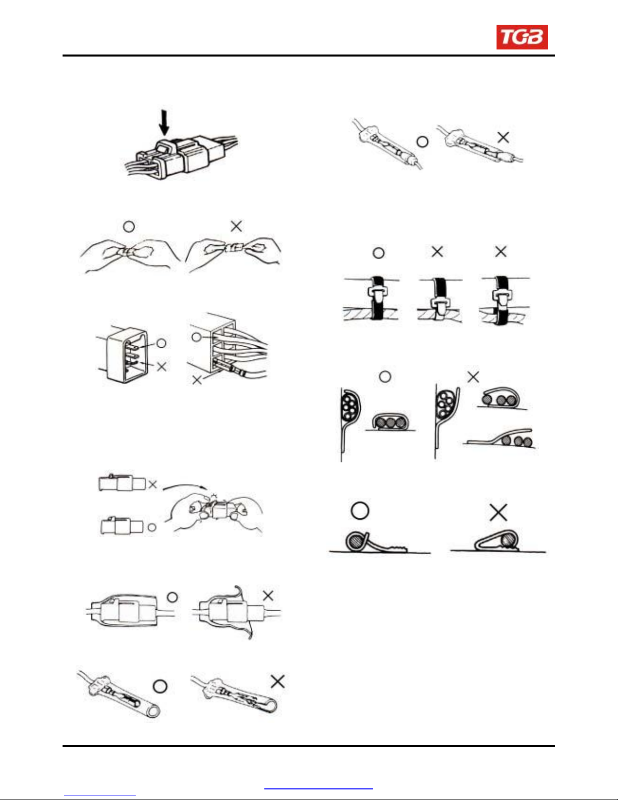
●
When separating a connector, it locker has to be
unlocked firstly.
operation.
Then, conduct the service
●
Insert the terminal completely.
Check if the terminal is covered by the boot.
Do not let boot open facing up.
●
Do not pull the wires as removing a connector
or wires. Hold the connector body.
●
Make sure if the connector pins are bent,
extruded or loosen.
●
Insert the connector completely.
If there are two lockers on two connector sides,
make sure the lockers are locked in properly.
Check if any wire loose.
●
Secure wires and wire harnesses to the frame
with respective wire bands at the designated
locations. Tighten the bands so that only the
insulated surfaces contact the wires or wire
harnesses.
●
Wire band and wire harness have to be
clamped secured properly.
●
Do not squeeze wires against the weld or its
clamp.
●
Check if the connector is covered by the twin
connector boot completely and secured
properly.
●
Before terminal connection, check if the boot is
crack or the terminal is loose.
1-6
PDF created with pdfFactory Pro trial version www.pdffactory.com
To this chapter contents
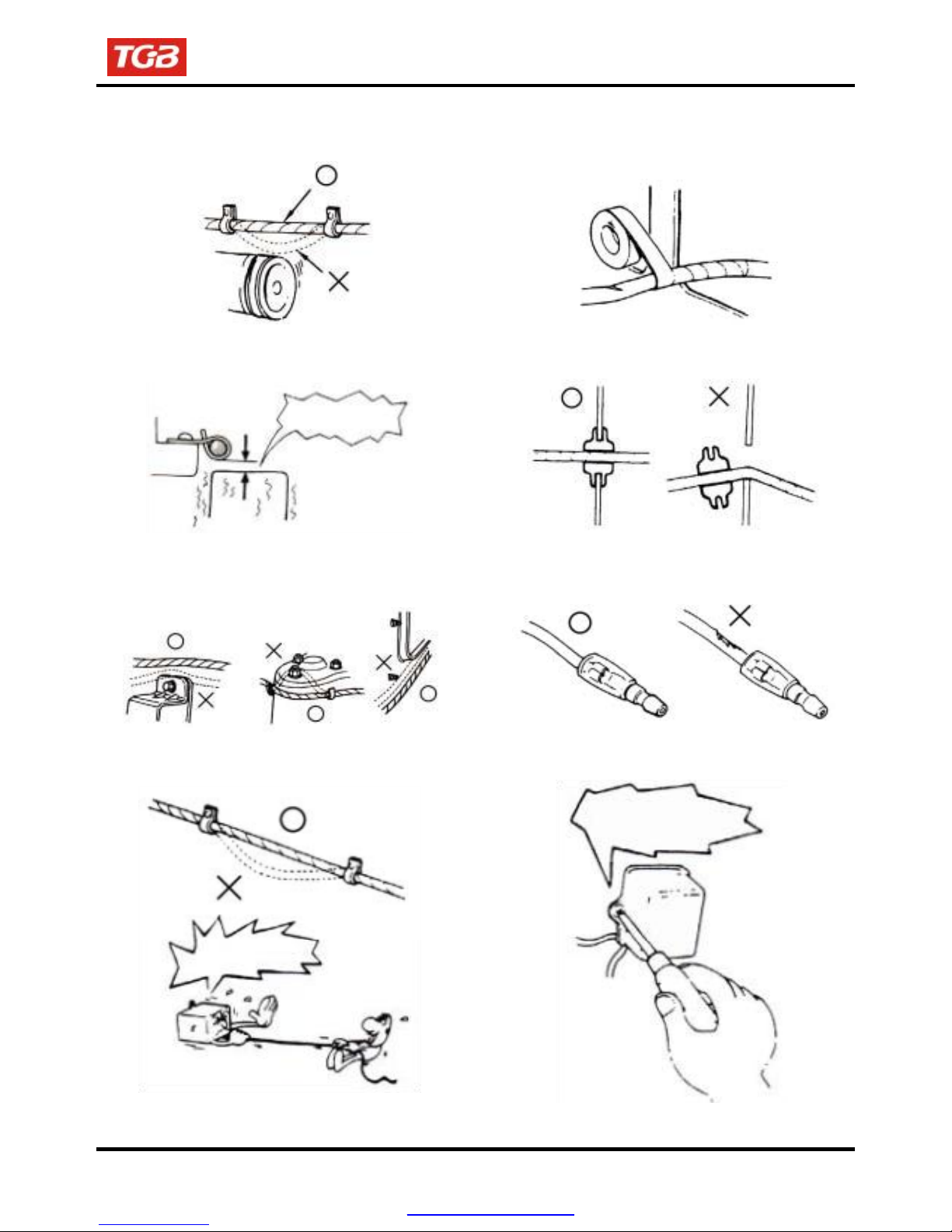
●
Do not let the wire harness contact with rotating,
moving or vibrating components as routing the
harness.
1. GENERAL INFORMATION
●
Protect wires or wire harnesses with electrical
tape or tube if they contact a sharp edge or
corner. Thoroughly clean the surface where
tape is to be applied.
●
Keep wire harnesses far away from the hot
parts.
●
Route wire harnesses to avoid sharp edges or
Never Touch
corners and also avoid the projected ends of
bolts and screws.
●
Route harnesses so that they neither pull too
tight nor have excessive slack.
Never too tight
●
Secure the rubber boot firmly as applying it on
wire harness.
●
Never use wires or harnesses which insulation
has been broken. Wrap electrical tape around
the damaged parts or replace them.
●
Never clamp or squeeze the wire harness as
installing other components.
Never clamp or
squeeze the wire
harness
1-7
PDF created with pdfFactory Pro trial version www.pdffactory.com
To this chapter contents
1. GENERAL INFORMATION
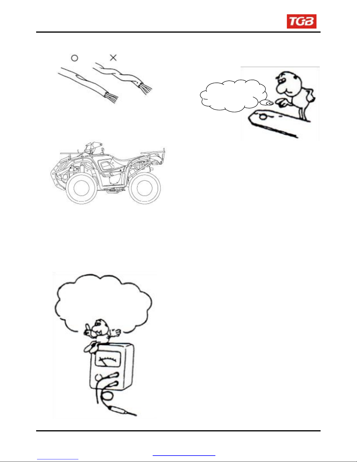
●
Do not let the wire harness been twisted as
installation.
●
Wire harnesses routed along the handlebar
should not be pulled too tight or have excessive
slack, be rubbed against or interfere with adjacent
or surrounding parts in all steering positions.
●
Before operating a test instrument, operator
should read the operation manual of the
instrument. And then, conduct test in
accordance with the instruction.
Do you know how to set the
instrument to its
measurement position and
the insert locations of its
two probes?
1-8
●
With sand paper to clean rust on connector
pins/terminals if found. And then conduct
connection operation later.
Clean rust
PDF created with pdfFactory Pro trial version www.pdffactory.com
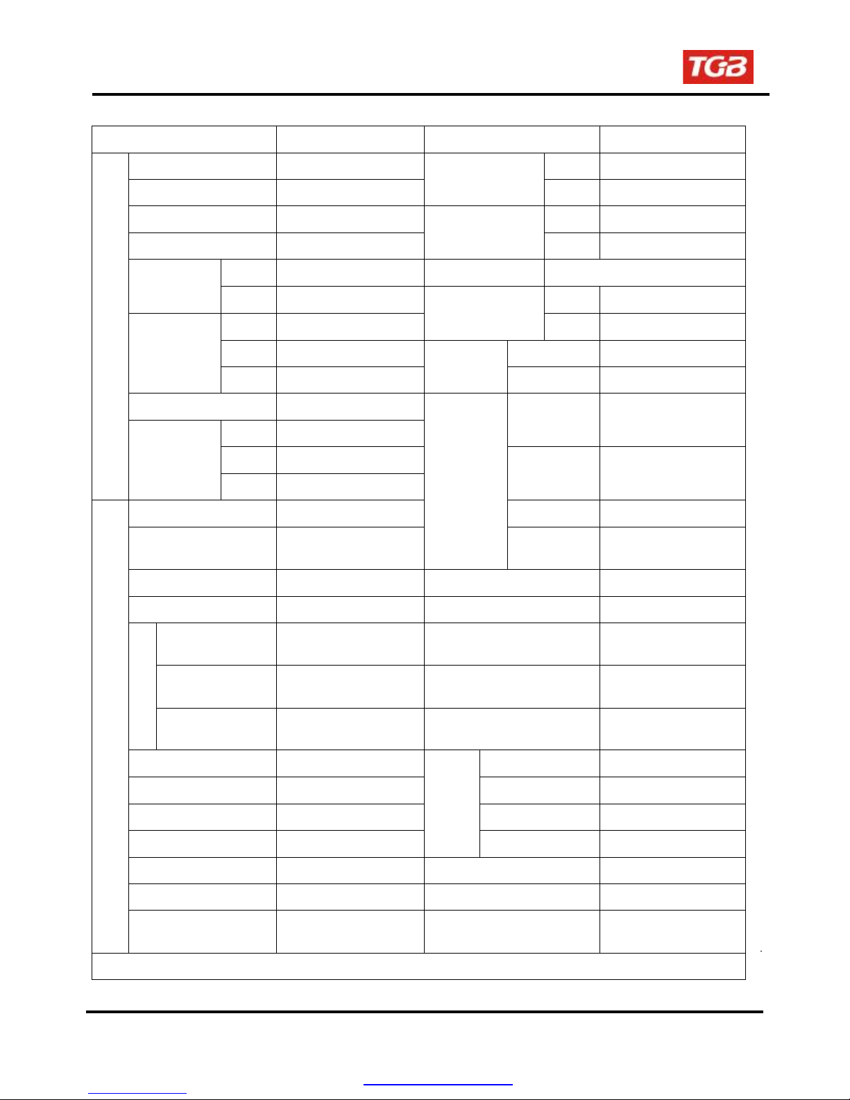
Specifications
To this chapter contents
1. GENERAL INFORMATION
MAKER
Overall Length 2160 mm Front Double arm
Overall Width 1160 mm
Overall Height 1175 mm Front AT22x7-10 (on road)
Wheel Base 1300 mm
Wheel tread
Curb
Weight
Passengers/ weight Two / 150 kg
Weight Dimension
Total
Weight
Type 4-Stroke Engine Clutch Centrifugal, dry type
Installation and
arrangement
Front 940 mm Rim Aluminum
Rear 890 mm Front
Front 137 kg
Rear 118 kg Max. Speed Above 86 km/hr
Total 255 kg
Front 179 kg
Rear 244 kg
Total 423 kg
Vertical, below
center, incline
TGB
Suspension
System
Tire
Specifications
Brake System
Performance
Reduction
MODEL
Rear Unit Swing
Rear AT22x10-10 (on road)
Disk (Ø 180mm)
Rear
Climb Ability Below 25゚
Primary
Reduction
Secondary
Reduction
Transmission
Disk (Ø 220mm)
Belt
Gear / Sprocket
C.V.T., auto speed
change
UA25A
Fuel Used Above 92 unleaded Speedometer 0 ~ 300 km/hr
Cycle/Cooling 4-stroke/Water cooled Horn 93 ~ 112dB/A
Bore
Stroke
Cylinder
Number/
Engine
Arrangement
Displacement
Compression Ratio
Max. HP
Max. Torque
Ignition
Starting System
Air filtration
Ø71 mm
63 mm
Single Cylinder
249.4 cc
10.5 : 1
14.7kw / 6500rpm
23.5Nm / 5500rpm
C.D.I.
Electrical starter
Sponge
Muffler
Exhaust Pipe Position
and Direction
Lubrication System
Exhaust
E.E.C.
P.C.V.
Catalytic reaction control
system
PDF created with pdfFactory Pro trial version www.pdffactory.com
Solid Particulate
CO
HC
Concentration
Nox
Expansion & Pulse
Type
Left side, and
Backward
Forced circulation &
splashing
Below 7.0 g/ km
Below 1.5g/ km
Below 0.4g/ km
─
─
─
1-9
1. GENERAL INFORMATION
To this chapter contents
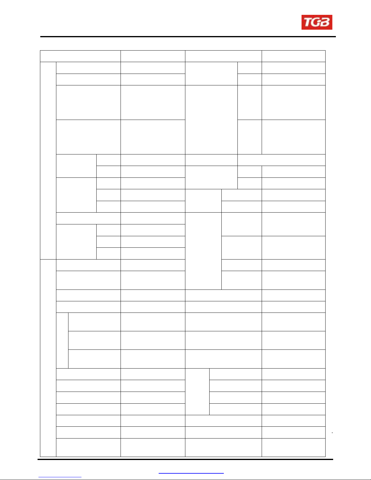
Specifications
MAKER
Overall Length 2160 mm Front Double arm
Overall Width 1160 mm
Overall Height 1205 mm Front AT25x8-12 (on road)
Wheel Base 1300 mm
Wheel tread
Curb
Weight
Passengers/ weight Two / 150 kg
Weight Dimension
Total
Weight
Type 4-Stroke Engine Clutch Centrifugal, dry type
Installation and
arrangement
Front 940 mm Rim Aluminum
Rear 890 mm Front
Front 145 kg
Rear 129 kg Max. Speed Above 86 km/hr
Total 274 kg
Front 186 kg
Rear 256 kg
Total 442 kg
Vertical, below
center, incline
TGB
Suspension
System
Tire
Specifications
Brake System
Performance
Reduction
MODEL
Rear Unit Swing
Rear AT25x10-12 (on road)
Disk (Ø 180mm)
Rear
Climb Ability Below 25゚
Primary
Reduction
Secondary
Reduction
Transmission
Disk (Ø 220mm)
Belt
Gear / Sprocket
C.V.T., auto speed
change
UA25C
1-10
Fuel Used Above 92 unleaded Speedometer 0 ~ 300 km/hr
Cycle/Cooling 4-stroke/Water cooled Horn 93 ~ 112dB/A
Bore
Stroke
Cylinder
Number/
Engine
Arrangement
Displacement
Compression Ratio
Max. HP
Max. Torque
Ignition
Starting System
Air filtration
Ø71 mm
63 mm
Single Cylinder
249.4 cc
10.5 : 1
14.7kw / 6500rpm
23.5Nm / 5500rpm
C.D.I.
Electrical starter
Sponge
Muffler
Exhaust Pipe Position
and Direction
Lubrication System
E.E.C.
P.C.V.
Catalytic reaction control
system
Solid Particulate
CO
HC
Exhaust
Concentration
Nox
Expansion & Pulse
Type
Left side, and
Backward
Forced circulation &
splashing
Below 7.0 g/ km
Below 1.5g/ km
Below 0.4g/ km
─
─
─
PDF created with pdfFactory Pro trial version www.pdffactory.com
1. GENERAL INFORMATION
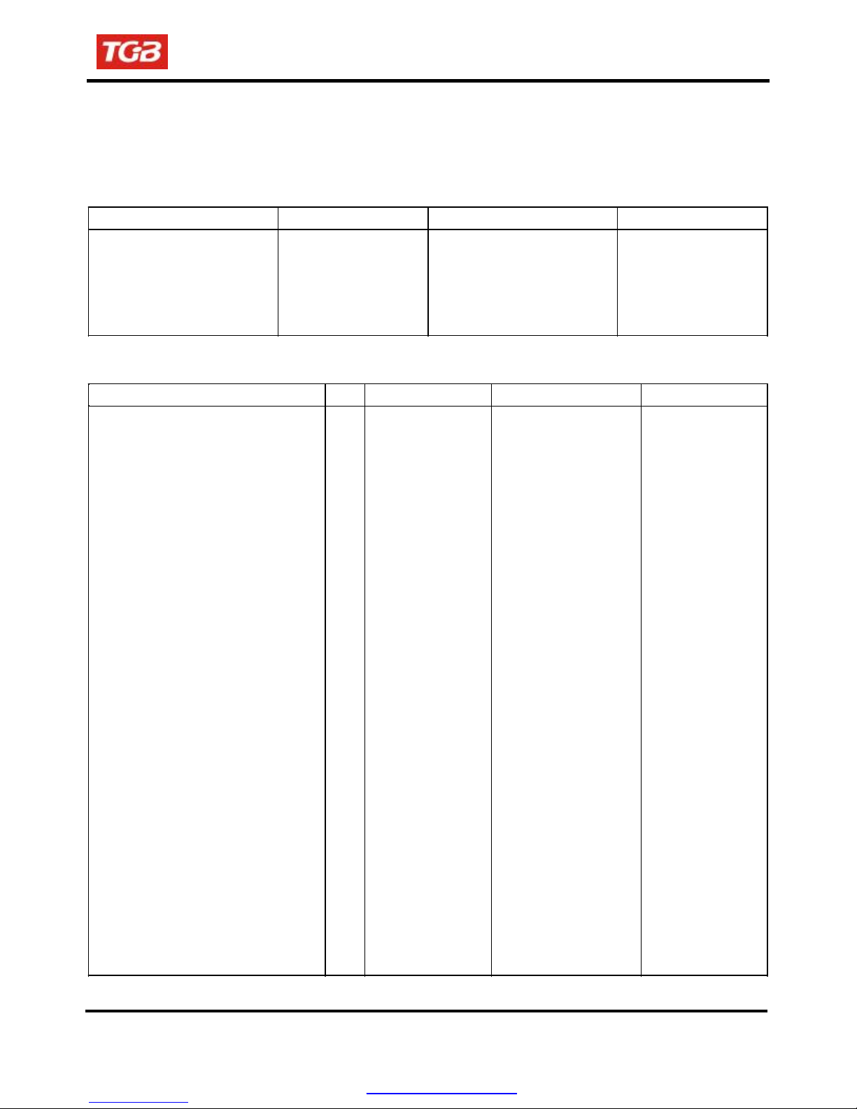
Specifications
MAKER
Overall Length 2155 mm Front Double arm
Overall Width 1170 mm
Overall Height 1175 mm Front
Wheel Base 1300 mm
Wheel tread
Curb
Weight
Weight Dimension
Passengers/ weight Two / 150 kg
Total
Weight
Front 890 mm Rim Aluminum
Rear 940 mm Front
Front 156 kg
Rear 129 kg Max. Speed Above 86 km/hr
Total 285 kg
Front 190kg
Rear 260 kg
Total 450 kg
TGB
Suspension
System
Tire
Specifications
Brake System
Performance
Reduction
MODEL
Rear Unit Swing
AT22x7-10
AT25x8-12
AT23x8-12
AT22x10-10
Rear
Rear
Climb Ability Below 25゚
Primary
Reduction
Secondary
Reduction
AT25x10-12
AT23x10-10
Disk (Ø 180mm)
Disk (Ø 220mm)
Belt
Gear / Sprocket
ATV300C.C.
Type 4-Stroke Engine Clutch Centrifugal, dry type
Installation and
arrangement
Fuel Used Above 92 unleaded Speedometer 0 ~ 300 km/hr
Cycle/Cooling 4-stroke/Water cooled Horn 93 ~ 112dB/A
Bore
Stroke
Cylinder
Number/
Engine
Arrangement
Displacement
Compression Ratio
Max. HP
Max. Torque
Ignition
Starting System
Air filtration
Vertical, below
center, incline
Ø75 mm
65 mm
Single Cylinder
287.2 cc
8.8 : 1
15kw / 6500rpm
24.7Nm / 5500rpm
C.D.I.
Electrical starter
Sponge
Transmission
Muffler
Exhaust Pipe Position
and Direction
Lubrication System
E.E.C.
P.C.V.
Catalytic reaction control
system
Solid Particulate
CO
HC
Exhaust
Concentration
Nox
C.V.T., auto speed
change
Expansion & Pulse
Type
Left side, and
Backward
Forced circulation &
splashing
Below 7.0 g/ km
Below 1.5g/ km
Below 0.4g/ km
─
─
─
PDF created with pdfFactory Pro trial version www.pdffactory.com
1. GENERAL INFORMATION
To this chapter contents
Torque Values
The torque values listed in above table are for more important tighten torque values. Please see standard
values for not listed in the table.
Standard Torque Values for Reference
5 mm bolt、nut
6 mm bolt、nut
8 mm bolt、nut
10 mm bolt、nut
12 mm bolt、nut
Type
Engine Torque Values
Cylinder stud bolt
Cylinder head nut
Cylinder head right bolt
Cylinder head side cover bolt
Cylinder head cover bolt
Cylinder head stud bolt (inlet pipe) 2
Cylinder head stud bolt (EX. pipe)
Air inject pipe bolt
Air inject reed valve bolt
Tappet adjustment screw nut
Spark plug
Tensioner lifter bolt
Carburetor insulator bolt
Oil pump screw
Water pump impeller
Engine left cover bolt
Engine oil draining bolt
Engine oil strainer cap
Mission draining bolt
Mission filling bolt
Shift drum fixing bolt
Clutch driving plate nut
Clutch outer nut
Drive face nut
ACG. Flywheel nut
Crankcase bolts
Mission case bolt
Item
Tighten Torque
0.45~0.6kgf-m 5 mm screw
0.8~1.2kgf-m 6 mm screw、SH nut
1.8~2.5kgf-m 6 mm bolt、nut
3.0~4.0kgf-m 8 mm bolt、nut
5.0~6.0kgf-m 10 mm bolt、nut
Q’ty Thread Dia. (mm) Torque Value(kgf-m) Remarks
4
4
2
2
4
2
4
2
4
1
2
2
2
1
9
1
1
1
1
1
1
1
1
1
7
7
10
8
8
6
6
6
8
6
3
5
10
6
6
3
7
6
12
30
8
12
14
28
14
14
14
6
8
Type
1.0~1.4
3.6~4.0
2.0~2.4
1.0~1.4
1.0~1.4
1.0~1.4
2.4~3.0
1.0~1.4
0.07~0.09
0.7~1.1
1.0~1.2
1.0~1.4
0.7~1.1
0.1~0.3
1.0~1.4
1.1~1.5
3.5~4.5
1.3~1.7
1.1~1.5
3.5~4.5
3.5~4.5
5.0~6.0
5.0~6.0
8.5~10.5
5.0~6.0
0.8~1.2
2.6~3.0
Tighten Torque
0.35~0.5kgf-m
0.7~ 1.1kgf-m
1.0 ~1.4kgf-m
2.4 ~3.0kgf-m
3.5~4.5kgf-m
Apply oil to thread
1-12
PDF created with pdfFactory Pro trial version www.pdffactory.com

1. GENERAL INFORMATION
To this chapter contents
Frame Torque Values
Handlebar upper holder bolt
Steering shaft nut
Steering tie-rod nut
Knuckle nut
Steering shaft holder bolt
Tie rod lock nut
Handlebar under holder nut
Front wheel nut
Front axle castle nut
Rear axle castle nut
Rear wheel nut
Engine hanger nut
Rear axle holder bolt
Drive gear bolt
Driven gear nut
Swing arm pivot bolt
Front suspension arm nut
Front
/ Rear cushion mounting bolt
Brake lever nut
Brake hose bolt
Brake caliper bolt
Brake disk mounting bolt
Air-bleed valve
Exhaust muffler mounting bolt
Exhaust muffler connection nut
Item
Q’ty Thread Dia. (mm) Torque Value(kgf-m) Remarks
4
6
1
10
4
10
2
10
2
8
4
10
2
8
8
10
2
14
2
14
8
10
4
12
4
12
2
10
4
10
1
14
4
6
2
6
13
10
6
6
11
8
3
5
2
8
2
7
10
10
1-13
PDF created with pdfFactory Pro trial version www.pdffactory.com
2.40
5.00
5.00
5.00
3.40
3.60
4.00
2.40
5.00
5.00
2.40
8.50
9.20
4.6
4.6
9.20
5.00
4.60
1.00
3.50
3.25
4.25
0.50
3.00
1.20
To this chapter contents
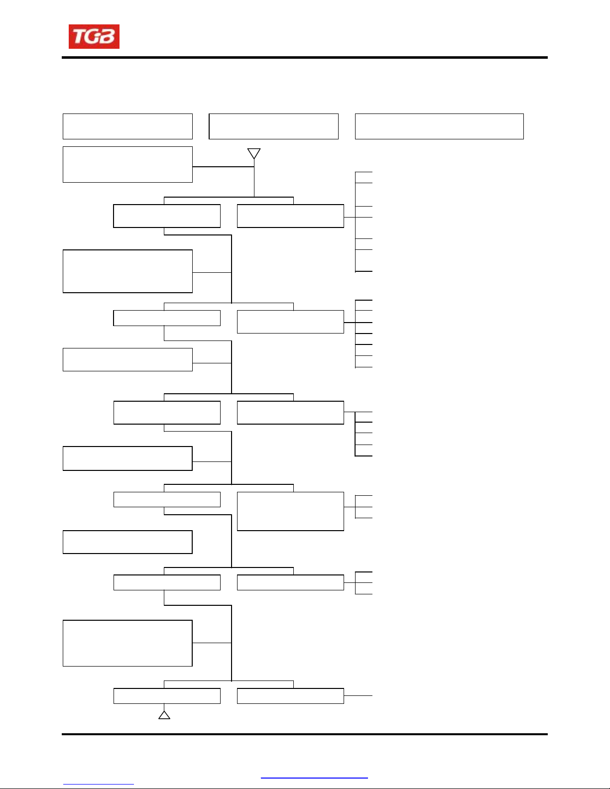
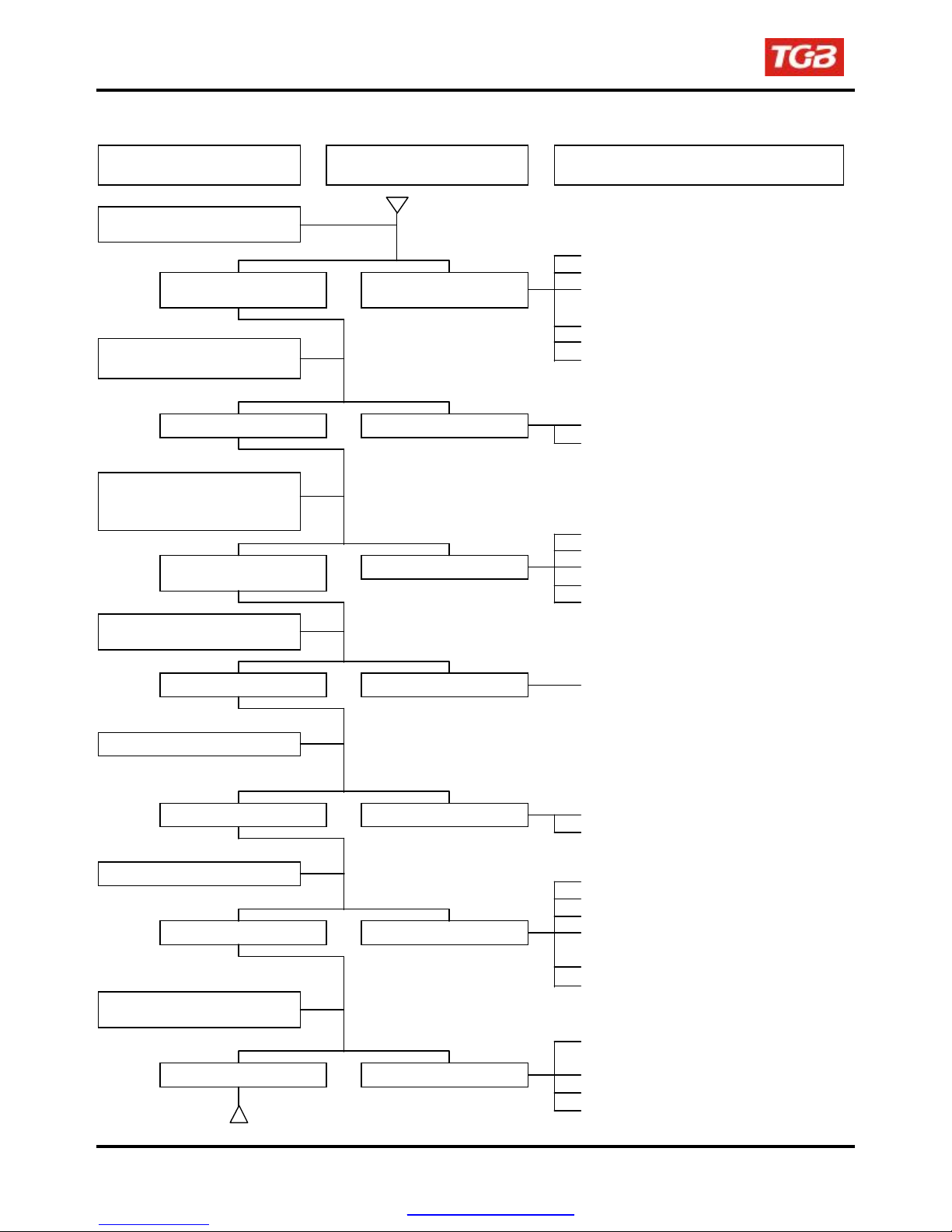
Troubles Diagnosis
A. Engine hard to start or can not be started
Check and adjustment
Loosen carburetor drain bolt to
check if there is gasoline inside
the carburetor
Fuel supplied tom
carburetor sufficient
Remove spark plug, install it
into spark plug cap, and perform a
spark test against engine ground.
Check if sparks Weak sparks, no spark at
Perform cylinder compression
pressure test.
Cylinder compression
pressure normal
Re-start by following the starting
procedures
No ignition There are some signs of
Remove the spark plug again
and check it.
Dry spark plug Wet spark plug
Fault condition
No fuel is supplied to
carburetor
all
Low compression
pressure or no pressure
ignition; nut engine can
not be started
Remove carburetor after 30
minutes and connect a hose
onto fuel rich circuit. Then blow
the hose with air
Blowing in normal Blowing clogged
1. GENERAL INFORMATION
Probable causes
●
No fuel in fuel tank
●
Check if the pipes, fuel tank to carburetor
and intake vacuum, are clogged.
●
Float valve clogged
●
Lines in fuel tank evaporation
system clogged
●
Malfunction of fuel pump
●
Loosen or damaged fuel pump
vacuum hose
●
Fuel filter clogged
●
Malfunction of spark plug
●
Spark plug foul
●
Malfunction of CDI set
●
Malfunction of AC generator
●
Ignition coil is in open or short circuit
●
Ignition coil leads open or short circuit
●
Malfunction of main switch
●
Piston ring seized
●
Malfunction of cylinder valves
●
Worn cylinder and piston ring
●
Cylinder gasket leak
●
Sand hole in compression parts
●
Malfunction of throttle valve operation
●
Air sucked into intake manifold
●
Incorrect ignition timing
●
Fuel level in carburetor too high
●
Malfunction of throttle valve operation
●
Throttle valve opening too wide
●
Malfunction of automatic by- starter
1-14
PDF created with pdfFactory Pro trial version www.pdffactory.com
1. GENERAL INFORMATION
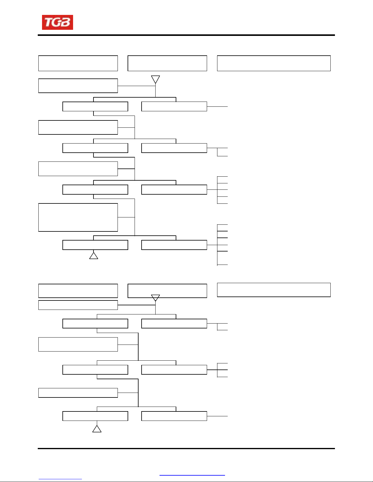
B. Engine run sluggish (Speed does not pick up, lack of power)
To this chapter contents
Check and adjustment Fault condition Probable causes
Try gradual acceleration and
check engine speed
Engine speed can be
increased.
Check ignition timing (Using
ignition lamp)
Ignition timing correct Incorrect ignition timing
Check cylinder compression
pressure (using compression
pressure gauge)
Compression pressure
Check if carburetor jet is
clogged
Remove spark plug
Check if engine over heat
Continually drive in acceleration
or high speed
correct
No clogged Clogged
No foul or discoloration Fouled and discoloration
Normal Engine overheat
No knock Knock
Engine speed can not be
increased.
No compression pressure
●
Air cleaner clogged
●
Poor fuel supply
●
Lines in fuel tank evaporation
system clogged
●
Exhaust pipe clogged
●
Fuel nozzle clogged in carburetor.
●
Fuel nozzle clogged in carburetor.
●
Malfunction of CDI
●
Malfunction of AC alternator
●
Cylinder & piston ring worn out
●
Cylinder gasket leaked
●
Sand hole in compression parts
●
Valve deterioration
●
Seized piston ring
●
Remove foreign
●
Remove dirt
●
Incorrect spark plug heat range
●
Piston and cylinder worn out
●
Lean mixture
●
Poor fuel quality
●
Too much carbon deposited
in combustion chamber
●
Ignition timing too advanced
●
Poor circuit on the cooling system
●
Too much carbon deposited
in combustion chamber
●
Lean mixture
●
Poor fuel quality
●
Ignition timing too advanced
1-15
PDF created with pdfFactory Pro trial version www.pdffactory.com
1. GENERAL INFORMATION
C. Engine runs sluggish (especially in low speed and idling)
To this chapter contents
Check and adjustment
Fault condition
Check ignition timing (using
ignition lamp)
Normal Abnormal
Adjust the air screw of
carburetor
Good Poor
Air sucked through carburetor
gasket
No air sucked Air sucked
Remove spark plug, install spark
plug into spark plug cap and
perform spark test against
engine ground
Good spark Poor
D. Engine runs sluggish (High speed)
Check and adjustment
Check ignition timing
Fault condition
Normal Abnormal
Check for fuel supplying system
in automatic fuel cup
Good Abnormal
Check if carburetor clogged
No clogged Clogged
Probable causes
●
Incorrect ignition timing (malfunction of
CDI or AC alternator)
●
Rich mixture (loosen the screw)
●
Lean mixture (tighten the screw)
●
Poor heat insulation gasket
●
Carburetor lock loose
●
Poor intake gasket
●
Poor carburetor O-ring
●
Vacuum hose crack
●
Spark plug fouled
●
Malfunction of CDI
●
Malfunction of AC generator
●
Malfunction of ignition coil
●
Open or short circuit in spark plug leads
●
Malfunction of main switch
Probable causes
●
Malfunction of CDI
●
Malfunction of AC alternator
●
Insufficient fuel in fuel tank
●
Fuel filter clogged
●
Restricted fuel tank vent
●
Cleaning
1-16
PDF created with pdfFactory Pro trial version www.pdffactory.com
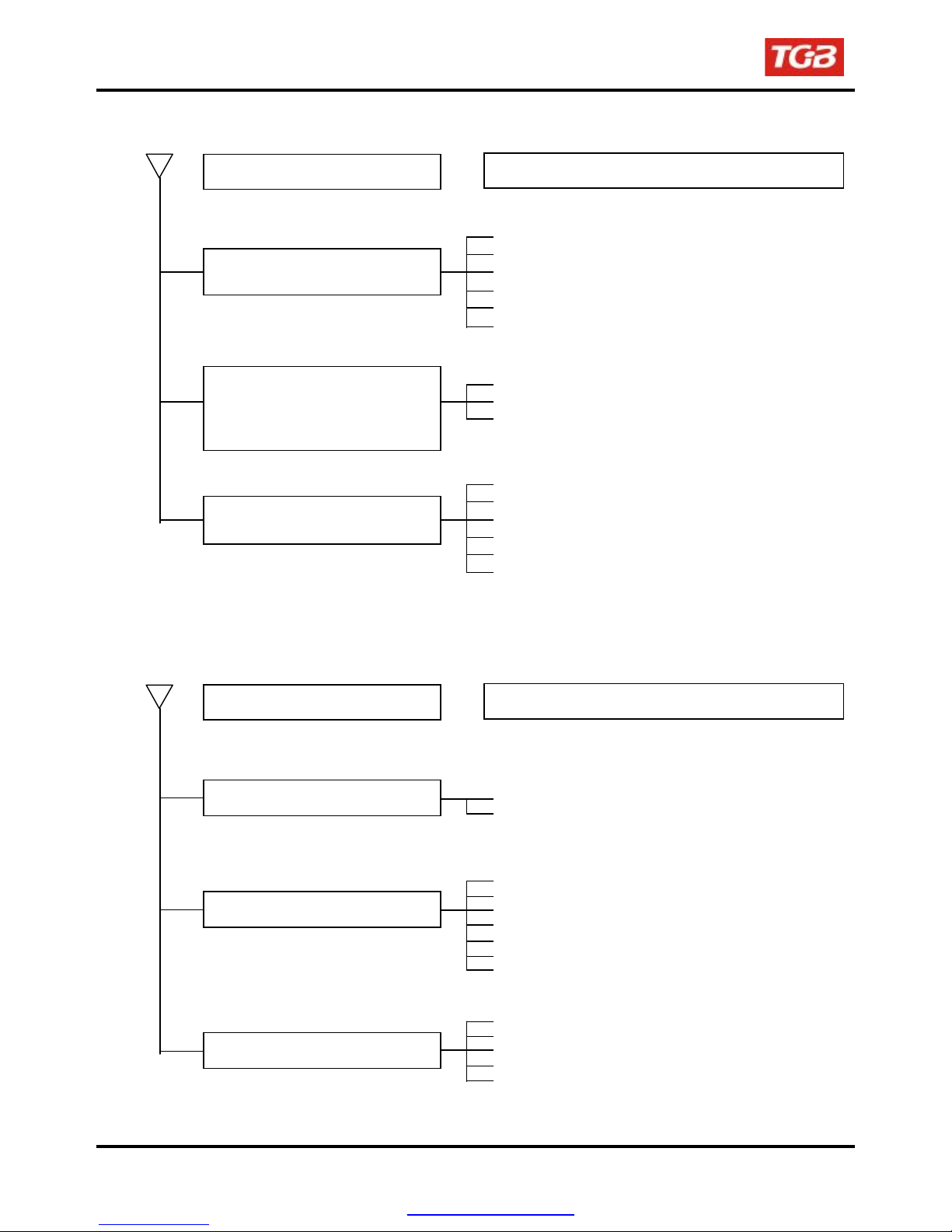
1. GENERAL INFORMATION
E. Clutch, driving and driving pulley
To this chapter contents
FAULT CONDITIONS
Engine can be started but
motorcycle can not be moved.
Engine running and misfire as
motorcycle initial forward moving or
jumping suddenly (rear wheel rotating
as engine in running)
Poor initial driving (Poor climbing
performance)
F. Poor handling
FAULT CONDITIONS
Steering is heavy
One wheel is wobbling
Vehicle pulls to one side
1-17
PROBABLE CAUSES
●
Drive belt worn out or deformation
●
Ramp plate of movable drive face damaged
●
Driving pulley spring broken
●
Clutch weights broken
●
Drive slide-shaft gear groove broken
●
Transmission gear damaged
●
Clutch weights spring broken
●
Clutch outer stuck with clutch weights
●
Connection parts in clutch and shaft worn out or burned
●
Drive belt worn out or deformation
●
Weight roller worn out
●
Movable drive face shaft worn out
●
Driven pulley spring deformation
●
Driven pulley shaft worn out
●
Greased in drive belt and driven face.
PROBABLE CAUSES
●
Damaged steering bearing
●
Damaged steering shaft bushing
●
Bent rim
●
Improperly installed wheel hub
●
Excessive wheel bearing play
●
Bent swing arm
●
Bent frame
●
Swing arm pivot bushing excessively
●
Worn
●
Bent tie-rod
●
Incorrect tie-rod adjustment
●
Rear tie air pressure incorrect
●
Improper wheel alignment
●
Bent frame
PDF created with pdfFactory Pro trial version www.pdffactory.com
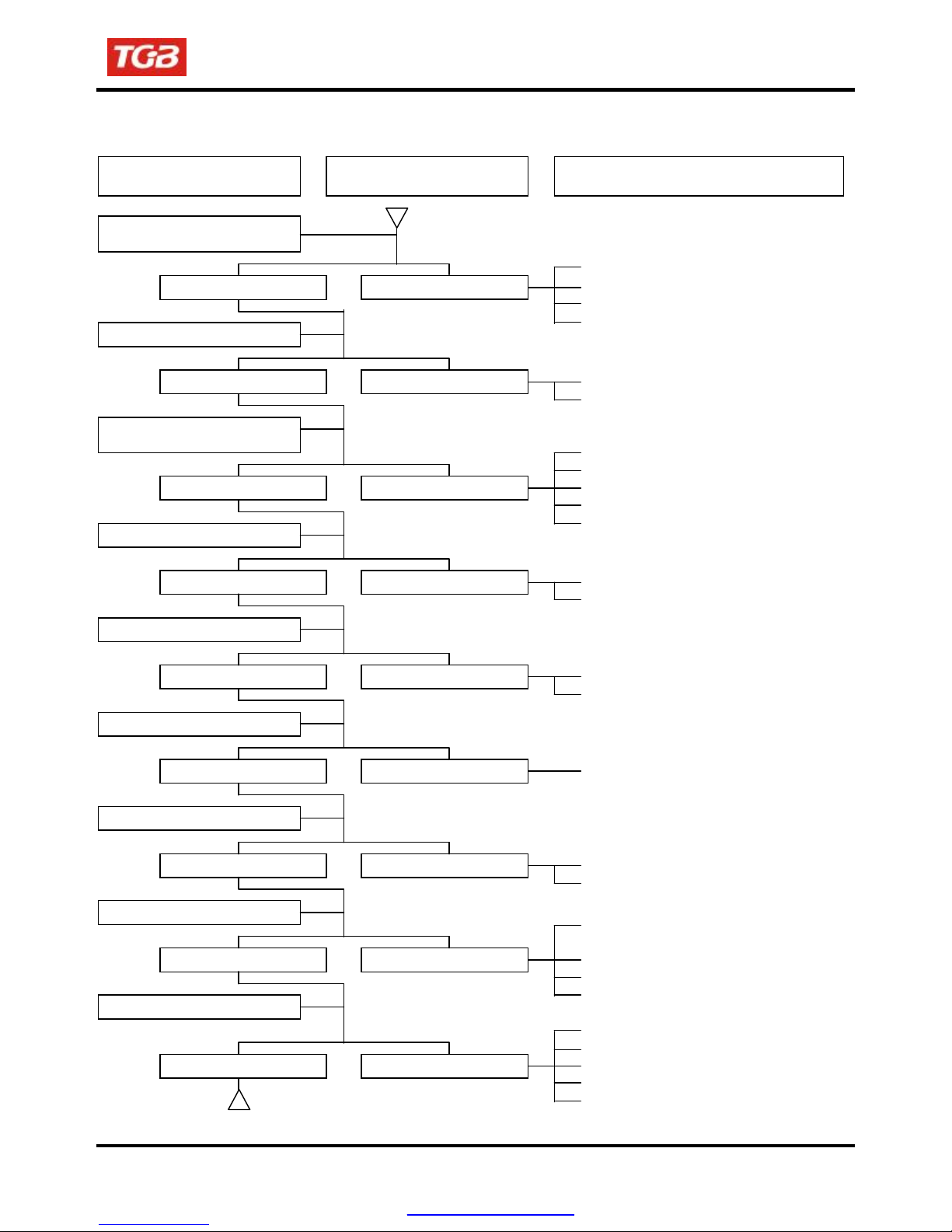
G. Loss power
Check and adjustment
Raise wheels off ground and
spin by hand
Spin freely Abnormal
Check tire pressure
Accelerate lightly, engine speed
can be increase
Check ignition timing
Test cylinder compression
Check carburetor
Check spark plug
Check for engine overheating
Accelerate or run at high speed
Normal Abnormal
Normal Abnormal
Normal Abnormal
Normal Abnormal
Normal Clogged
Normal Fouled or discolored
Normal Overheating
Normal Knocks
To this chapter contents
1. GENERAL INFORMATION
Fault condition
●
●
●
●
Probable causes
Brake dragging
Drive chain too tight
Damaged wheel bearing
Wheel bearing needs lubrication
●
Punctured tire
●
Faulty tire valve
●
Fuel / air mixture ratio too rich or lean
●
Clogged in air cleaner
●
Clogged in muffler
●
Restricted fuel flow
●
Clogged fuel tank cap breather hole
●
Faulty pulse generator
●
Faulty CDI unit
●
Leaking head gasket
●
Worn cylinder and piston rings
●
Clean
●
Clean the spark plug
●
Spark plug is incorrect heat range
●
Excessive carbon deposited
in combustion chamber
●
Wrong type of fuel
●
Fuel / air mixture ratio is lean
●
Use of poor quality fuel
●
worn piston and cylinder
●
Fuel / air mixture ratio is lean
●
Wrong type of fuel
●
Ignition timing too advanced
●
Excessive carbon deposited
in combustion chamber
1-18
PDF created with pdfFactory Pro trial version www.pdffactory.com
1. GENERAL INFORMATION
To this chapter contents
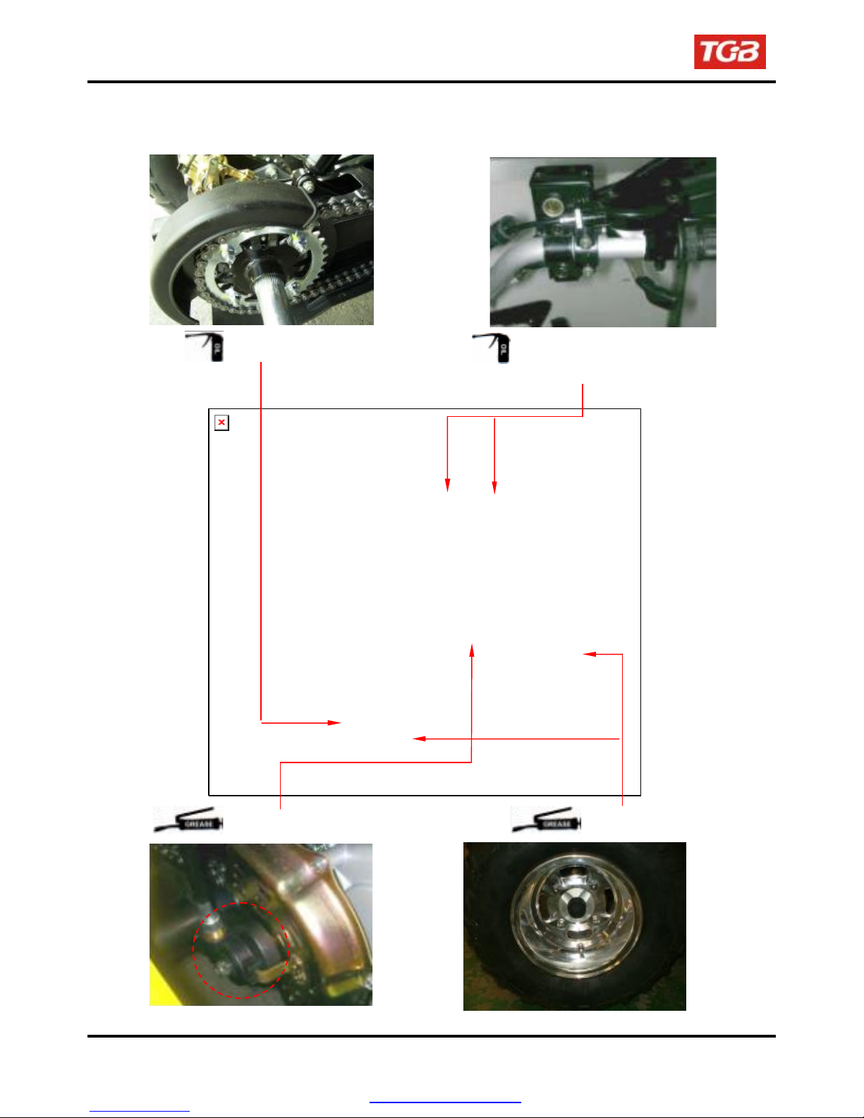
Lubrication Points
1-19
Drive chain
Speedometer gear
Acceleration cable/ Front & rear brake
lever pivot
Wheel bearing
PDF created with pdfFactory Pro trial version www.pdffactory.com
Precautions in Operation ···················· 2-1
Home page Contents
Periodical Maintenance Schedule ······ 2-2
Fuel Lines ············································· 2-3
Acceleration Operation ······················· 2-3
Air Cleaner············································ 2-3
Spark Plug ············································ 2-3
Valve Clearance ··································· 2-4
Carburetor Idle Speed Adjustment····· 2-5
Ignition System ···································· 2-6
Cylinder Compression Pressure ········ 2-6
Drive Belt ·············································· 2-7
Precautions in Operation
Specification
Transmission Gear oil
Capacity of coolant
Fuel Tank Capacity
Engine Oil
Clearance of throttle valve
Spark plug
“F” Mark in idling speed
Full timing advanced
Idling speed
Cylinder compression pressure
Valve clearance
Tire dimension
Tire pressure (cold)
Battery
Capacity
Change
Capacity
Change
Engine + radiator
Reservoir upper
Type
Gap
Front
Rear
3 ±1 psi / 5 ±1 psi
2. MAINTENANCE INFORMATION
Drive Chain ··········································· 2-7
Brake System (Disk Brake) ················· 2-8
Brake Light Switch/Starting Inhibitor
Switch ··················································· 2-9
Headlight Beam Distance ···················· 2-10
Clutch Disc Wear ································· 2-10
Cushion················································· 2-10
Steering Handle···································· 2-11
Wheel/Tire············································· 2-11
Nuts, Bolts Tightness ·························· 2-11
Special Tools List ································ 2-12
BTDC 10º / 1700 rpm
BTDC 27º / 4000 rpm
12.0 ±2 kgf/cm²
IN:0.10 ± 0.02 mm
12V12Ah (MF battery) type:
12000 c.c.
1400 c.c.
1200 c.c.
750 c.c.
650 c.c.
850 c.c.
420 c.c.
1~3 mm
NGK CR8E
0.8 mm
1700±100 rpm
EX:0.15 ± 0.02 mm
AT22x7-10 / AT25x8-12
AT22x10-10 / AT25x10-12
2
2-1
PDF created with pdfFactory Pro trial version www.pdffactory.com

2. MAINTENANCE INFORMATION
Periodical Maintenance Schedule
Maintenance
Code
1 Air cleaner I C R
2 Fuel filter I I R
3 Oil filter C C
4 Engine oil change R Check daily.Replace every 3000km or 3 months
5 Tire pressure/condition I Check daily
6 Battery inspection I I
7 Brake & free ply check I I
8 Steering handle check I I
9 Suspension operation check I I
10 All nut/bolts torque check I I
11 Gear oil check for leaking I I
12 Spark plug check or change I I R
13 Gear oil R Check monthly.Replace every 6000 km or 6 months
14 Frame lubrication L
15 Exhaust pipe I I
16 Ignition timing I I
17 Idling emission check A I
18 Throttle operation I I
19 Engine bolts torque check I I
20 CVT driving device(belt) I R
21 CVT driving device(rollers) C R
22 Drive chain I / L I / L C
23
24 Fuel lines I I
25 Cam chain I I
26 Valve clearance I A
27 Cooling hoses/connections I I
28 Coolant reservoir I I
29 Coolant I I R
30 Brake fluid I I Replace every 2 years
Code: I = Inspection, cleaning, and adjustment R = Replacement A = Adjustment
C ~ Cleaning (replaced if necessary) L = Lubrication
Have your ATV checked, adjusted, and recorded maintenance data periodically by your TGB Authorized Dealer to
maintain the ATV at the optimum condition
The above maintenance schedule is established by taking the monthly 1000 kilometers as a reference which ever
comes first.
Remarks: 1. Clean or replace the air cleaner element more often when the ATV is operated on dusty roads or in
Lights/electrical
equipment/multi-meters
the Heavily- polluted environment.
2. Maintenance should be performed more often if the ATV is frequently operated in high speed and
after the ATV has accumulated a higher mileage.
3. Preventive maintenance
a. Ignition system-Perform maintenance and check when continuous abnormal ignition, misfire,
after-burn, overheating occur.
b. Carbon deposit removal-Remove carbon deposits in cylinder head, piston heads, exhaust system
when power is obvious lower. Than ever
Item
Inital
500KM
I Check daily
3 Month every
2-2
PDF created with pdfFactory Pro trial version www.pdffactory.com
To this chapter contents
1,000KM
6 Month every
3,000KM
12 Month every
12,000KM
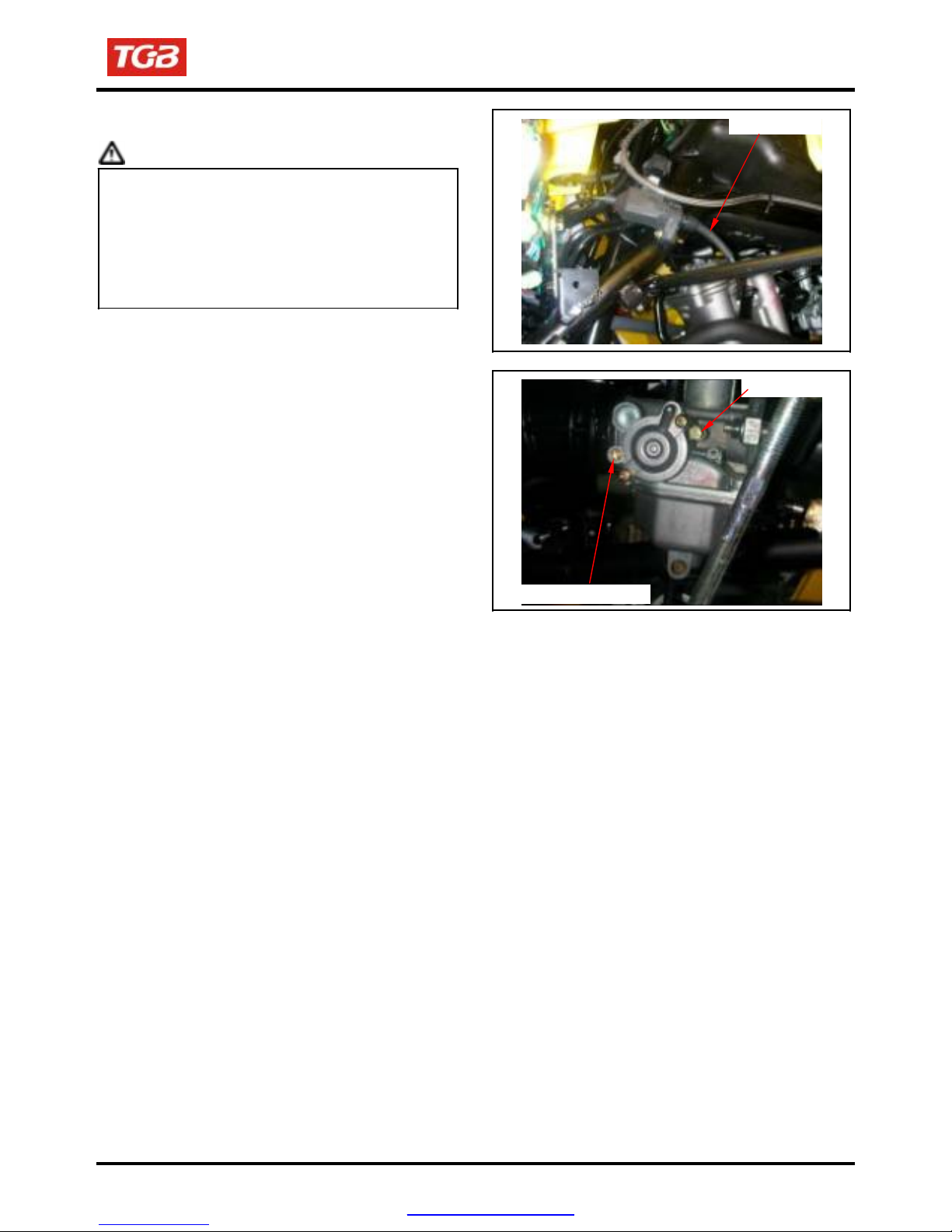
Loosen 2 screws and 2 bolts
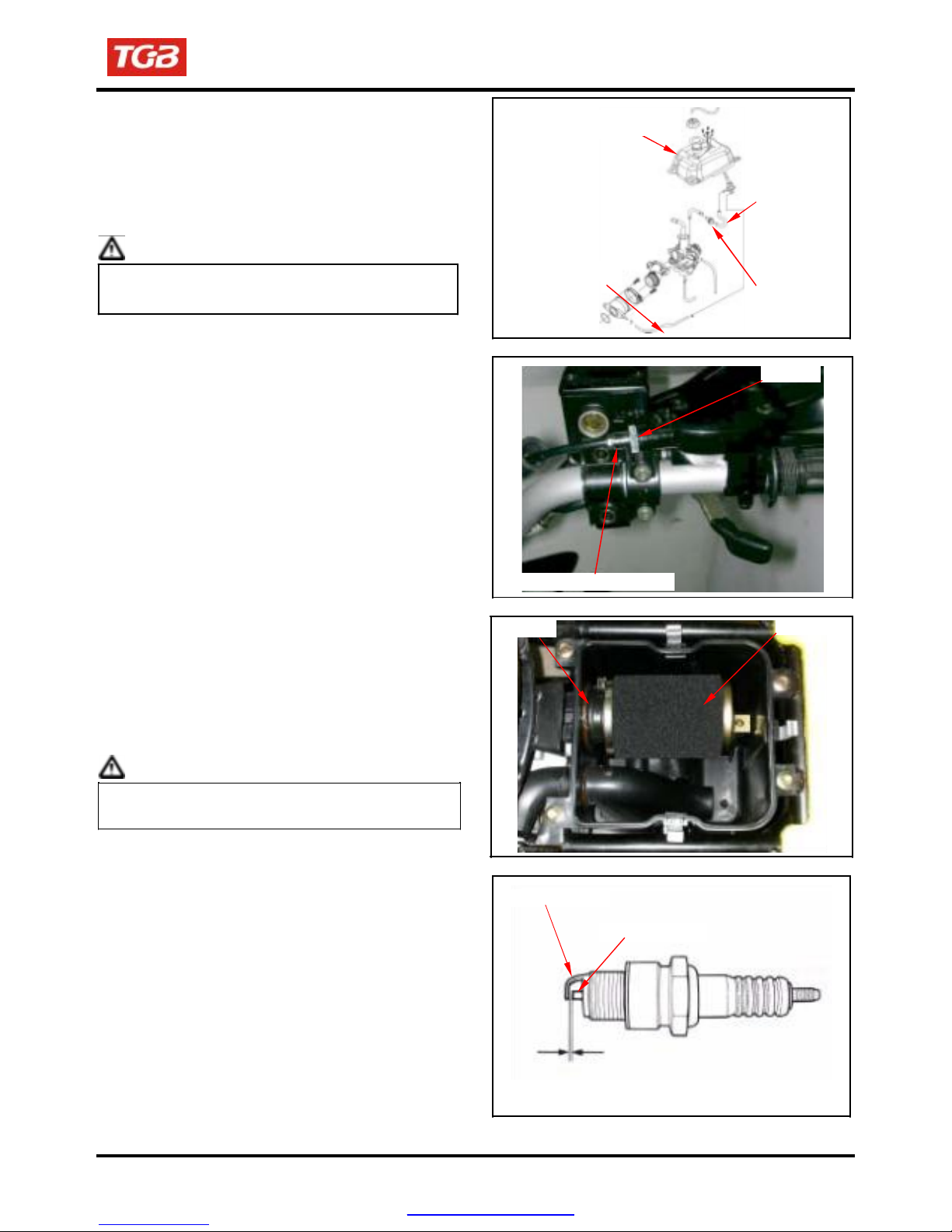
Fuel Lines
Remove the seat
Remove the tank cover
Check all lines, and replace it when they are
deterioration, damage or leaking
Warning
To this chapter contents
Gasoline is a low ignition material so any kind of
fire is strictly prohibited as dealing it.
Acceleration Operation
Have a wide open of throttle valve as handle in any
position and release it to let back original (full
closed) position.
Check handle if its operation is smooth.
Check acceleration cable and replace it if
deteriorated, twisted or damaged.
Lubricate the cable if operation is not smooth.
Measure the throttle lever free play in its flange
part.
Remove rubber boot, loosen fixing nut, and then
adjust it by turning the adjustment screw. Tighten
the fixing nut, and check acceleration operation
condition.
Free play: 1~3 mm.
Air Cleaner
Remove seat.
loosen 4 hooks from the air cleaner cover and
then remove the cover.
Loosen the clamp strip and 1 screw of air cleaner
element, and then remove the air cleaner element.
Clean the element with non-flammable or
high-flash point solvent and then squeeze it for
dry.
Caution
Never use gasoline or acid organized solvent to
clean the element.
Soap the element into cleaning engine oil and then
squeeze it out. Install the element onto the element
seat and then install the air cleaner cover.
Spark Plug
Recommended spark plug: CR8E
Remove spark plug cap.
Clean dirt around the spark plug hole.
Remove spark plug.
Measure spark plug gap.
Spark plug gap:0.8 mm
Carefully bend ground electrode of the plug to
adjust the gap if necessary.
Hold spark plug washer and install the spark plug
by screwing it.
Tighten the plug by turning 1/2 turn more with plug
socket after installed.
Tighten torque: 1.0~1.2kgf-m
2. MAINTENANCE INFORMATION
Vacuum hose
Throttle adjustment screw
Fuel tank
Clamp
Ground electrode
0.8~0.9mm
Central electrode
Fuel hose
Fuel filter
Lock nut
Element
2-3
PDF created with pdfFactory Pro trial version www.pdffactory.com
2. MAINTENANCE INFORMATION
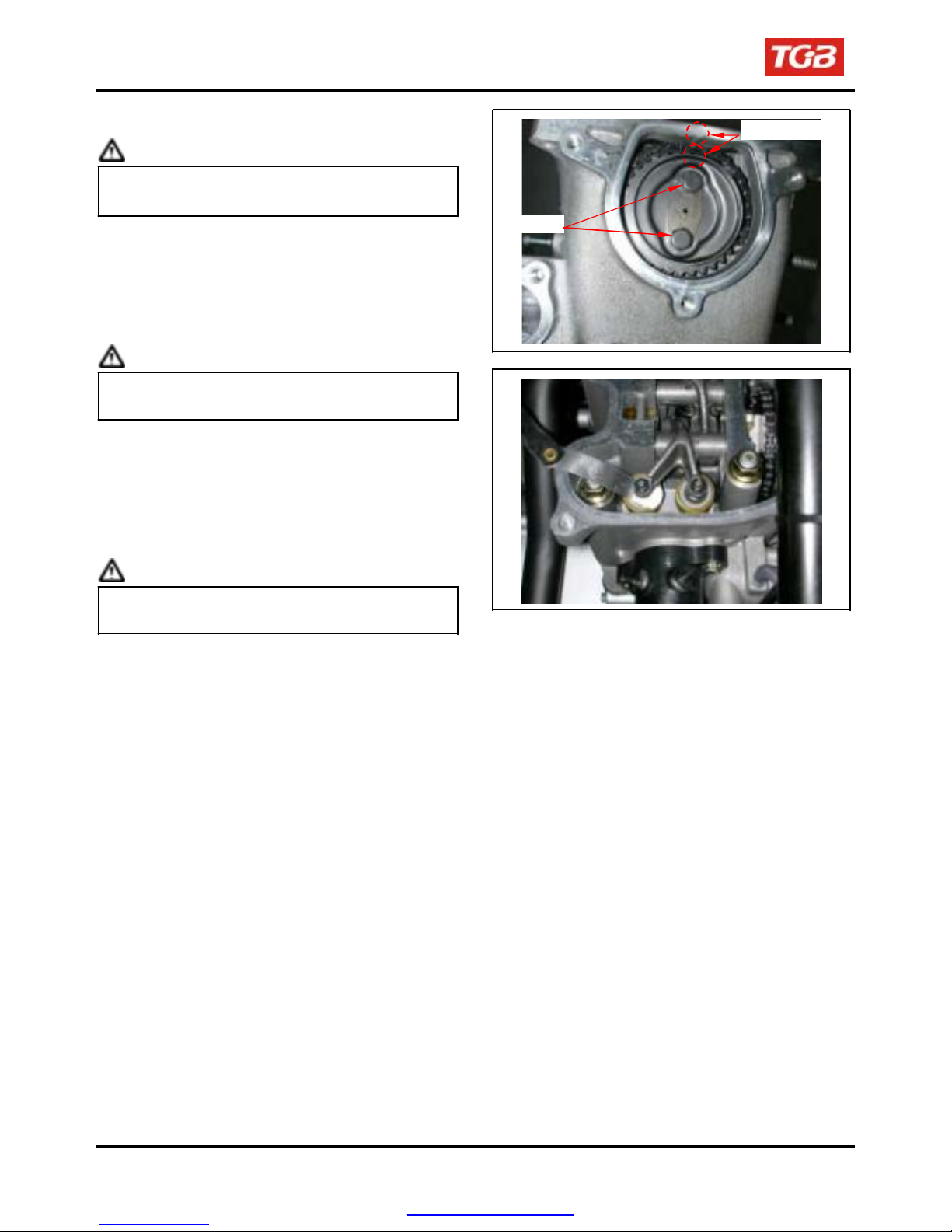
Valve Clearance
Caution
To this chapter contents
Checks and adjustment must be performed when
the engine temperature is below 35℃.
Remove front fender, fuel tank cover and fuel tank.
Remove cylinder head cover.
Remove cylinder head side cover.
Turn camshaft bolt in C.W. direction and let the “T”
mark on the camshaft sprocket align with cylinder
head mark so that piston is placed at TDC position in
compression stroke.
Caution
Do not turn the bolt in C.C.W. direction to prevent
from camshaft bolt looseness.
Valve clearance inspection and adjustment. Check
& adjust valve clearance with feeler gauge.
Standard Value: IN 0.10 ± 0.02 mm
EX 0.15 ± 0.02 mm
Loosen fixing nut and turn the adjustment nut for
adjustment.
Caution
Re-check the valve clearance after tightened the
fixing nut.
2-4
2 bolts
Timing mark
PDF created with pdfFactory Pro trial version www.pdffactory.com
To this chapter contents
Carburetor Idle Speed Adjustment
Caution
●
Inspection & adjustment for idle speed have to
be performed after all parts in engine that
needed adjustment have been adjusted.
●
Idle speed check and adjustment have to be
done after engine is being warm up. (It is
enough that operates engine from stop to
running for 10 minutes.)
Park the ATV with main stand and warm up
engine.
Connect tachometer (the wire clamp of tachometer is
connected to the high tension cable).
Turn the throttle valve stopper screw to specified
idle speed.
Specified idle speed(ATV250): 1700 ± 100 rpm
Specified idle speed(ATV300): 1600 ± 100 rpm
Emission adjustment in idle speed
Warm up the engine for around 10 minutes and
then conduct this adjustment.
1. Connect the tachometer onto engine.
2. Adjust the throttle valve stopper screw and let
engine runs in 1600±100 rpm.
3. Insert the exhaust sampling pipe of exhaust
analyzer into the front section of exhaust pipe.
Adjust the air adjustment screw so that emission
value in idle speed is within standard.
4. Slightly accelerate the throttle valve and
release it immediately. Repeat this for 2~3
times.
5. Read engine RPM and value on the exhaust
analyzer. Repeat step 2 to step 4 procedures
until measured value within standard.
Emission standard CO: below 2.5~3.5%
PDF created with pdfFactory Pro trial version www.pdffactory.com
HC: below 2000ppm
2. MAINTENANCE INFORMATION
Ignition cable
Stopper screw
Air adjustment screw
2-5
2. MAINTENANCE INFORMATION
To this chapter contents
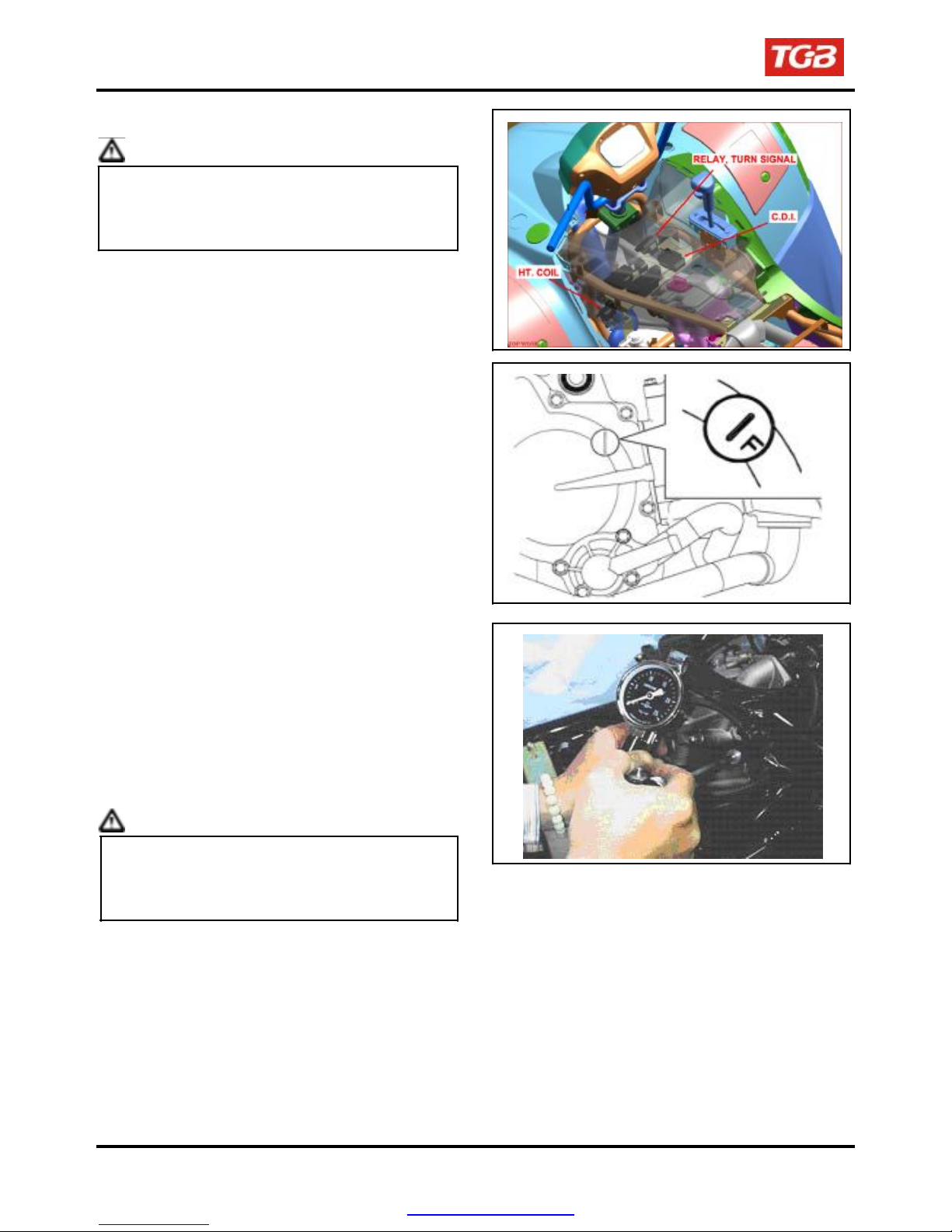
Ignition System
Caution
●
C.D.I ignition system is set by manufacturer so it
can not be adjusted.
●
Ignition timing check procedure is for checking
whether CDI function is in normal or not.
Connect tachometer and ignition light.
Start engine.
As engine in idle speed: 1600 rpm, aim at the mark
“F” with the ignition light.
that ignition timing is correct.
Then, it is means
Increase engine speed to 6000 rpm to check
ignition advance degree. If indent is located within
the ignition advance degrees, it is means that the
ignition advance degree is in normal.
If ignition timing is incorrect, check CDI set, pulse
rotor and pulse generator. Replace it if
malfunction of these parts is found.
Cylinder Compression Pressure
Warm up engine.
Turn off the engine.
Remove the trunk.
Remove the central cover.
Remove spark plug cap and spark plug.
Install compression gauge.
Full open the throttle valve, and rotate the engine
by means of starter motor.
Caution
Rotate the engine until the reading in the gauge
no more increasing.
Usually, the highest pressure reading will be
obtained in 4~7 seconds.
Compression pressure: 12 ± 2 Kg/cm²
Check following items if the pressure is too low:
●
Incorrect valve clearance.
●
Valve leaking.
●
Cylinder head leaking, piston, piston ring and
cylinder worn out.
If the pressure is too high, it means carbon
deposits in combustion chamber or piston head.
2-6
PDF created with pdfFactory Pro trial version www.pdffactory.com
 Loading...