

Page 1

7900S Series DVR
USER’S MANUAL
Version 1.0
This manual is written for DVR firmware version 1.0.
Page 2

PS-7900 Series User Manual
Preventive and Cautionary Tips
Before connecting and operating your DVR, please be advised of the following tips:
• Ensure unit is installed in a well-ventilated, dust-free environment.
• Unit is designed for indoor use only.
• Keep all liquids away from the DVR.
• Ensure environmental conditions meet factory specifications.
• Ensure unit is properly secured to a rack or shelf. Major shocks or jolts to the unit as a result of dropping it may cause
damage to the sensitive electronics within the unit.
• Use the DVR in conjunction with an UPS if possible.
• Power down the unit before connecting and disconnecting accessories and peripherals.
• A factory recommended HDD should be used for this device.
• Improper use or replacement of the battery may result in an explosion. Replace with the same or equivalent type only.
Dispose of used batteries according to the instructions provided by the battery manufacturer.
2
Page 3

PS-7900 Series User Manual
TABLE OF CONTENTS
Contents
C H A P T E R 1 Getting Started ............................................................................................................... 6
1.1 Starting and Shutting Down Your DVR .............................................................................................. 6
1.2 Rebooting and Locking Your DVR ...................................................................................................... 7
1.3 Setting Date & Time .......................................................................................................................... 8
1.4 Checking the Status of Your DVR .................................................................................................... 10
C H A P T E R 2 Live Feed ....................................................................................................................... 11
2.1 Watching a Live Feed ...................................................................................................................... 11
2.1.1 Understanding Live Feed Icons ................................................................................................ 11
2.1.2Operating the Live Feed ............................................................................................................ 12
2.2 Using the Display Menu .................................................................................................................. 15
2.3 Configuring Live Feed Displays ........................................................................................................ 17
2.4 Setting Camera Order ..................................................................................................................... 18
C H A P T E R 3 Record Settings ............................................................................................................. 19
3.1 Configuring Settings for Recording ................................................................................................. 19
3.1.1 Configuring Recording Settings ................................................................................................ 19
3.1.2 Configuring a Quick Recording Schedule .................................................................................. 20
3.1.3 Configuring an Advanced Recording Schedule ......................................................................... 21
C H A P T E R 4 Playback ....................................................................................................................... 23
4.1 Playing Back a Recording................................................................................................................. 23
4.1.1 Understanding the Playback Interface ..................................................................................... 23
4.2 Searching for Recorded Files ........................................................................................................... 24
4.3 Playing Back Recorded Files ............................................................................................................ 25
4.4 Playing Back Multiple Channels ...................................................................................................... 26
C H A P T E R 5 Backup .......................................................................................................................... 26
5.1 Backing Up Video Clips .................................................................................................................... 26
5.1.1 Selecting Video Clips ................................................................................................................ 26
3
Page 4

PS-7900 Series User Manual
5.2 Backing Up Video Clips .................................................................................................................... 28
5.3 Backing Up Recorded Files .............................................................................................................. 29
C H A P T E R 6 System Configuration ................................................................................................... 31
6.1 Configuring Network Settings ......................................................................................................... 31
6.1.1 Network configuration ...................................................................................................... 31
6.1.2 Extended remote connection ............................................................................................ 32
6.2 Managing User Accounts ................................................................................................................ 32
7.2.1 Adding a New Remote/Local User............................................................................................ 32
6.2.2 Deleting a User ......................................................................................................................... 33
6.2.3 Editing a User ........................................................................................................................... 34
6.2.4 Switch User .............................................................................................................................. 34
6.3 Configuring PTZ Cameras ................................................................................................................ 34
6.3.1 Configuring Basic PTZ Settings ................................................................................................. 35
6.4 Customizing PTZ Presets, Patterns and Patrols ............................................................................... 36
6.5 Configuring Alarms and Exceptions ............................................................................................... 37
6.5.1 Setting Up Motion Detection ................................................................................................... 37
6.5.2 Configuring Exceptions ............................................................................................................. 38
6.5.3 Configuring E-mail Settings ...................................................................................................... 39
C H A P T E R 7 Camera Management ................................................................................................... 40
7.1 To setup privacy zones: ................................................................................................................... 40
7.2 Configuring Video Tampering Detection ......................................................................................... 40
7.3 Configuring Video Loss Detection ................................................................................................... 41
7.4 Configuring OSD Settings ................................................................................................................ 42
C H A P T E R 8 Disk Management ......................................................................................................... 44
8.1 Managing Disks ............................................................................................................................... 44
8.1.1 Checking Disk Status ................................................................................................................ 44
8.2 Formatting Disk ............................................................................................................................... 44
8.2.1 Enabling Disk Overwrite ........................................................................................................... 45
8.3 Managing Files ................................................................................................................................ 45
8.3.1 Searching for Recorded Files .................................................................................................... 45
8.4 Locking and Unlocking Recorded Files ............................................................................................ 47
4
Page 5

PS-7900 Series User Manual
C H A P T E R 9 DVR Management ......................................................................................................... 48
9.1 Managing System ............................................................................................................................ 48
9.1.1 Upgrading the System Firmware .............................................................................................. 48
9.1.2 Restoring Default Settings ........................................................................................................ 48
9.2 Exporting & Importing Configuration .............................................................................................. 49
9.3 Viewing System Logs ....................................................................................................................... 50
9.4 Locking and Unlocking System Menus ............................................................................................ 51
5
Page 6

PS-7900 Series User Manual
C H A P T E R 1
Getting Started
1.1 Starting and Shutting Down Your DVR
Proper startup and shutdown procedures are crucial to expanding the life of your DVR.
To startup your DVR:
1. Ensure the power supply is plugged into an electrical outlet. It is HIGHLY recommended that an Uninterruptible Power
Supply (UPS) be used in conjunction with the unit.
2. Connect the DVR to a VGA monitor. You will only see the DVR menu system when it‟s connected to a VGA monitor.
3. Press the POWER switch on the back rear panel. The Power indicator LED should turn green. The unit will begin to
start.
4. After startup, the Power indicator LED will remain green. (Figure 9).
Figure 9. Startup Splash Screen
To shut down the DVR:
1. Enter the Shutdown menu, shown in Figure 10 by going to Main Menu > Maintenance > Shutdown.
6
Page 7

PS-7900 Series User Manual
Figure 10. Shutdown Menu
2. Select the Shutdown button.
3. Click the Yes button.
1.2 Rebooting and Locking Your DVR
While in the Shutdown menu (Figure 10), you may also reboot or lock your DVR. Locking your DVR will return you to the
Live Feed mode, which will require the correct administrator password to exit out of it. The Reboot button will reboot
your DVR.
To reboot or lock your DVR:
1. Enter the Shutdown menu by going to Main Menu > Maintenance > Shutdown.
2. Select the Lock button to lock the DVR or the Reboot button to reboot the DVR.
7
Page 8
PS-7900 Series User Manual
1.3 Setting Date & Time
It is extremely important to setup the system date and time to accurately timestamp recordings and events.
To setup date and time:
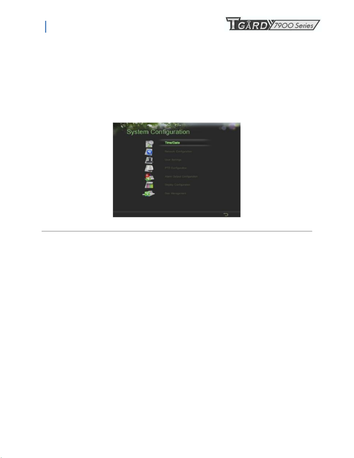
1. Enter the System Configuration menu by going to Main Menu > System Configuration, as shown in Figure 11.
Figure 11. System Configuration Menu
8
Page 9
PS-7900 Series User Manual
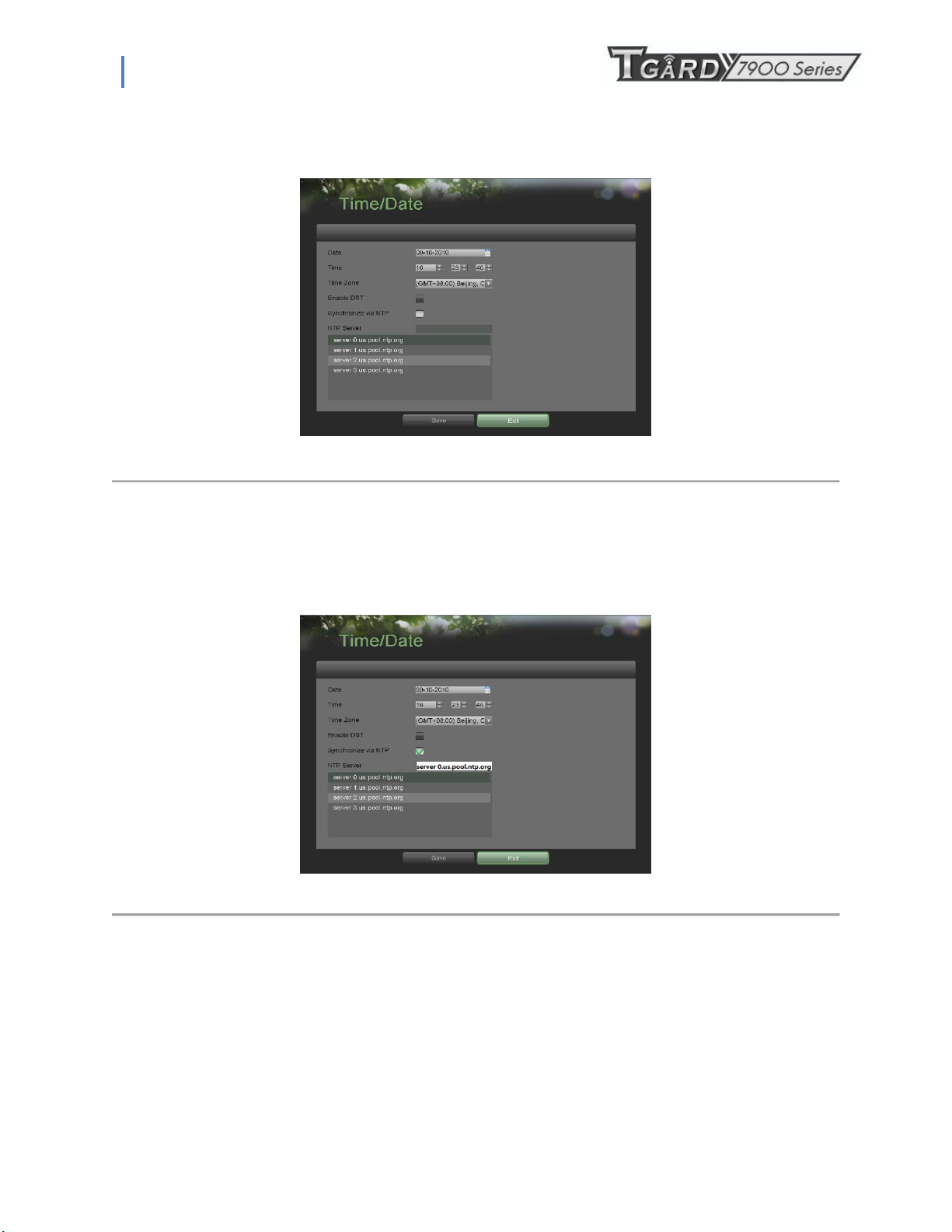
2. Click the Time/Date button to enter the Time/Date menu (Figure 12).
Figure 12. Time/Date Menu
3. The current system time and date as well as the time zone will be displayed. Using the directional buttons on the
front panel/remote or the mouse, select the correct date, time and time zone.
4. To enable Daylight Savings Time, click and check the Enable DST checkbox.
5. To acquire the time and date over an NTP (Network Time Protocol) Server, check the Synchronize via NTP
server checkbox. You may enter your own NTP server or select from one of the default locations from the list of
servers, as shown in Figure 13.
Figure 13. Time/Date Menu
6. Click the Save button to save settings and click the Exit button to exit out of the menu. Clicking the Exit button
without clicking the Save button will exit the menu without saving.
9
Page 10
PS-7900 Series User Manual
1.4 Checking the Status of Your DVR
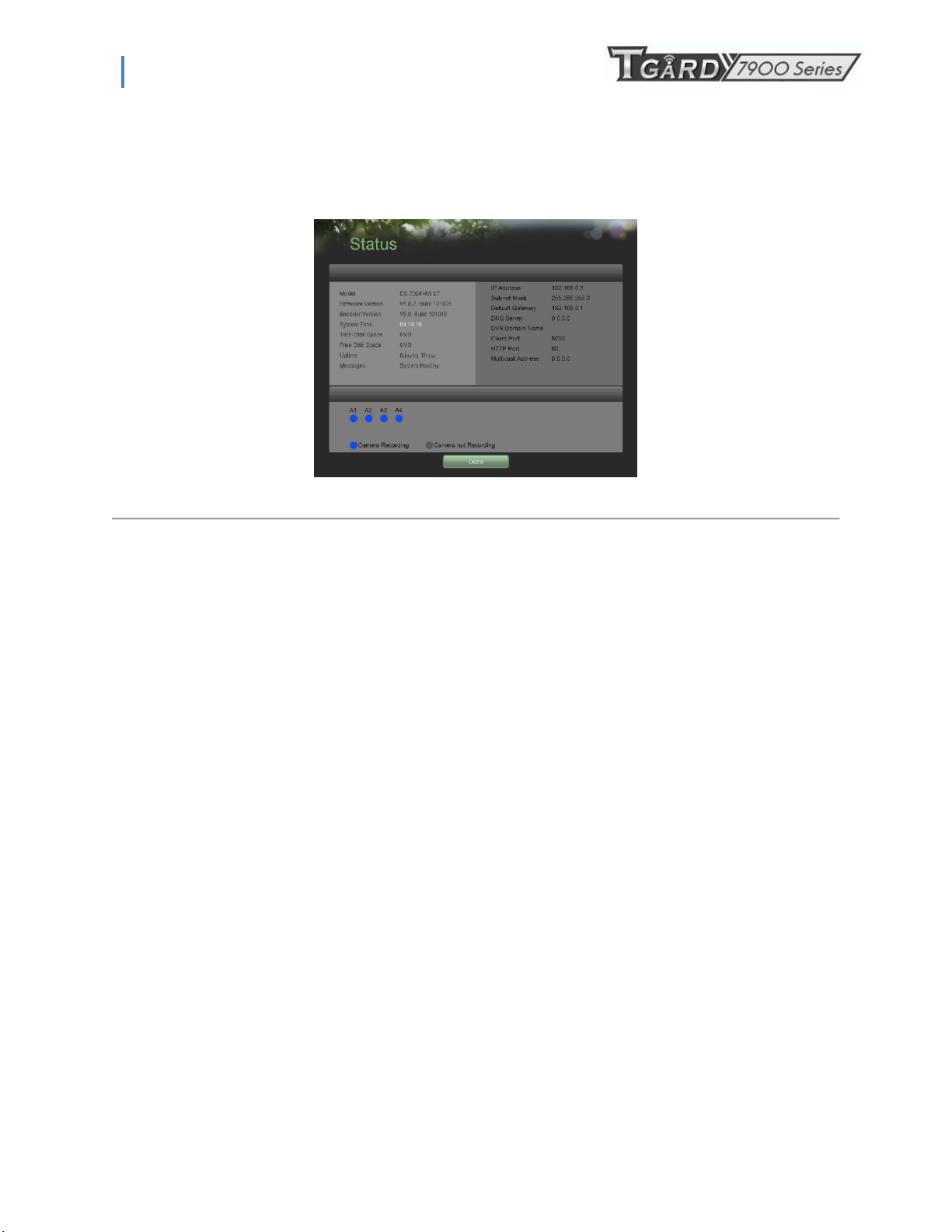
The current status of your DVR can be checked at any time by going to the Status menu. The Status menu, shown in Figure
14 can be accessed by going to Main Menu > Status.
Figure 14. Status Menu
The items that are found on the Status menu include:
• Model: The model number of the DVR.
• Firmware Version: The current firmware version installed on the DVR.
• Encoder Version: The current encoder version installed on the DVR.
• System Time: The current system time.
• Total Disk Space: Total disk space of the DVR.
• Free Disk Space: Total free disk space of the DVR.
• Uptime: The amount of time the DVR has been up and running.
• Messages: Displays the overall system status.
• IP Address: IP address that is set for the DVR.
• Subnet Mask: Subnet mask that is used for the DVR.
• Default Gateway: The default gateway that is set on the DVR.
• DNS Server: The DNS server that’s currently being used on the DVR.
• DVR Domain Name: The DVR domain name that is set for the DVR.
• Client/HTTP Port: The current ports being used for client and web access.
• Multicast Address: The multicast address that’s being used on the DVR.
• Camera Status: The recording status of the attached cameras. A blue circle denotes that the camera is recording
while a gray circle shows that it is not.
10
Page 11

PS-7900 Series User Manual
C H A P T E R 2
Live Feed
2.1 Watching a Live Feed
The Live Feed mode is automatically started after the DVR boots up. It is also at the very top of the menu hierarchy, thus
hitting the ESC button multiple times (depending on which menu you’re on) will bring you to the Live Feed mode.
2.1.1 Understanding Live Feed Icons
There are multiple icons on each display in Live Feed mode to indicate different camera status and settings. These icons
include:
Event Icon: Indicates video loss or tampering, motion detection and/or sensor alarm.
Record Icon: Indicates the current channel is recording. The recording may have been started manually, from a
schedule, and/or triggered from motion or alarm.
Picture Settings Icon: Adjust picture settings for selected display.
PTZ Control Icon: Enter PTZ control mode for the selected display.
Preset Icon: Recall PTZ preset.
Patrol Icon: Recall PTZ patrol.
Tour Icon: Recall PTZ tour.
Zoom In/Zoom Out: Zoom in/out with PTZ.
Full Screen/Exit Full Screen Icon: Enter into/exit out of full screen mode for selected display.
Audio On/Audio Off Icon: Enable/disable audio for selected display.
Close Icon: Exit out of current setting and return to previous mode.
Figure 15. Live Feed Icons
11
Page 12
PS-7900 Series User Manual
2.1.2Operating the Live Feed
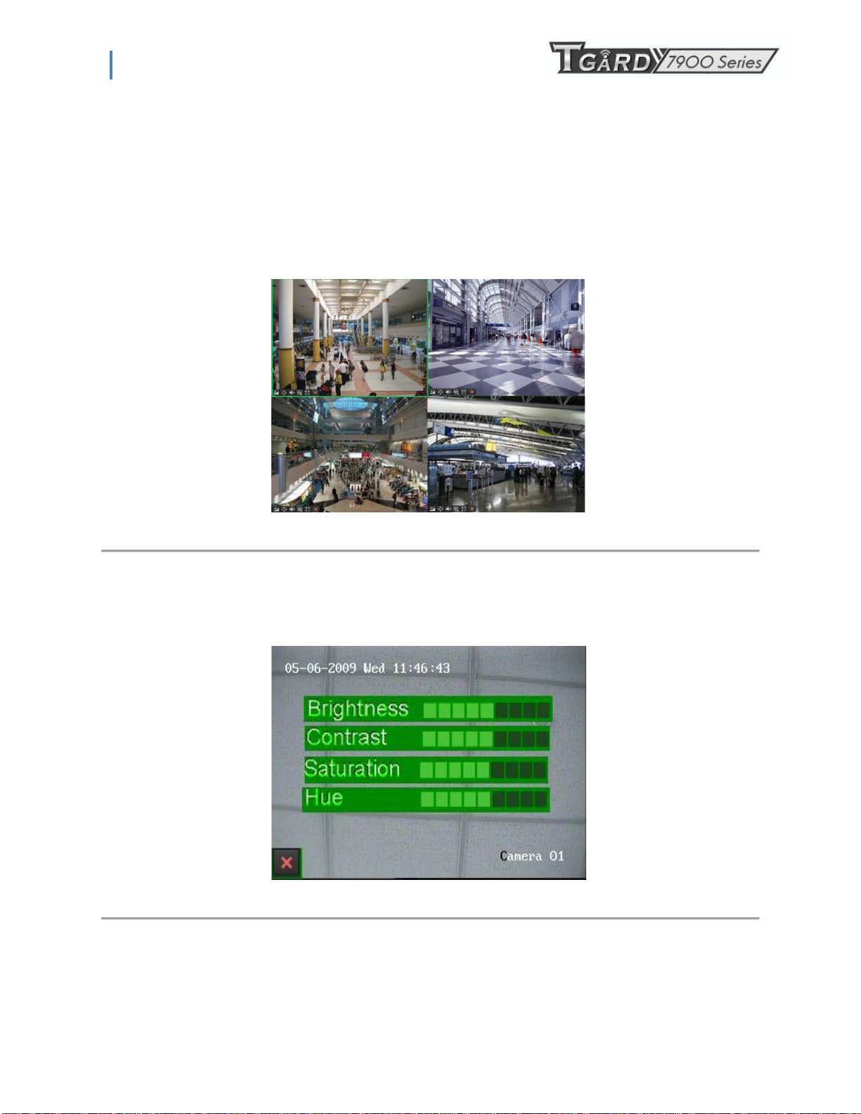
In Live Feed mode, you may adjust the settings for individual cameras by left-clicking on the desired display with the
mouse. The selected display will be surrounded with a green border, as shown in Figure 16.
Figure 16. Live Feed Mode
The settings you may adjust with each display includes:
• Picture Settings: Settings for the brightness, contrast, saturation and hue of selected display. To adjust the picture
settings of a display:
1. Select display.
2. Click the Picture Settings icon. This will bring up the Picture Settings menu, as shown in .Figure 17
Figure 17. Picture Settings Menu
3. Increase/decrease amount for brightness, contrast, saturation and hue. The affect will be displayed immediately
on the screen.
4. Click the Close icon to save the settings and return to the Live Feed mode.
12
Page 13

PS-7900 Series User Manual
13
Page 14
PS-7900 Series User Manual
• PTZ Control: If the selected camera is a PTZ camera, you may control it directly from the display. To control a PTZ
camera:
1. Select display that corresponds to a PTZ camera.
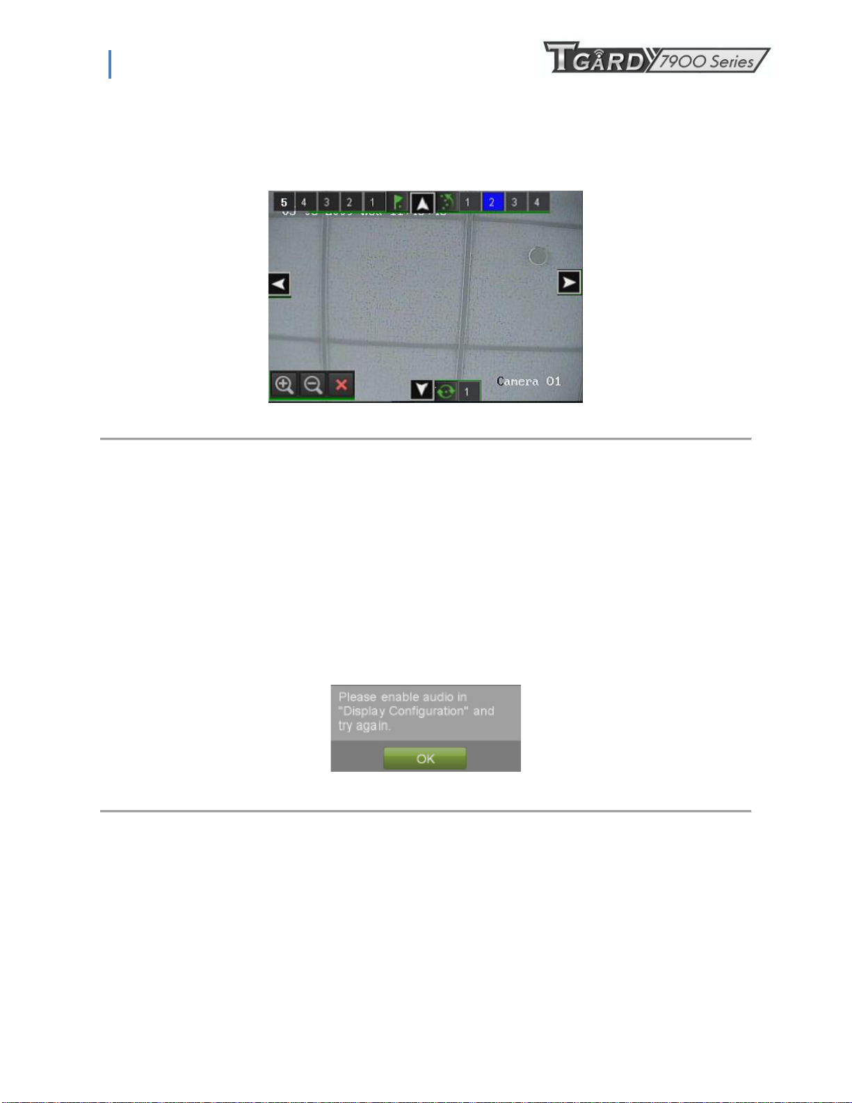
2. Click the PTZ Control icon. This will bring up additional PTZ control buttons, as shown in Figure 18.
Figure 18. PTZ Control Mode
1. Control the PTZ using PTZ control buttons. Pan and tilt PTZ by clicking on the directional buttons. Zoom in and
out using the Zoom In/Out buttons and recall presets, patrols and patterns by clicking the number next to the
corresponding icons.
2. Click the Close icon to return to Live Feed mode.
Note: PTZ parameters for the camera must be set correctly before the PTZ can be controlled.
Note: A maximum of five presets, four patrols and patterns can be displayed on this interface.
More presets, patrols and patterns can be recalled in the PTZ Configuration menu.
• Audio: Enable/disable audio for selected display. To enable or disable audio:
1. Select display to enable/disable audio.
2. Enable audio by clicking the Enable Audio icon and disable audio by clicking the Disable Audio icon. An error
message similar to the one shown in Figure 19 will pop up if the Enable Audio option is not selected in the
Display Configuration menu for the specified channel.
Figure 19. Enable Audio Error Window
• Digital Zoom Mode: Enable digital zoom on the selected channel. Once enabled, the regular feed will be shown in the
lower right corner while the zoomed in view will be shown on the full screen. The zoomed in region may be changed by
moving the red rectangle in the regular feed window.
• Full Screen Mode: Enable full screen mode for selected display. To enable full screen mode:
1. Select display to enable full screen on.
2. Click the Full Screen icon.
3. Click the Exit Full Screen icon to return to normal display mode.
14
Page 15
PS-7900 Series User Manual
2.2 Using the Display Menu
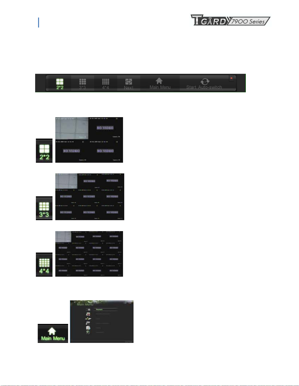
The Display Menu can be accessed by right-clicking the mouse on any of the display in Live
Feed mode. The Display menu, shown in Figure 20 allows you to quickly change into
different display modes and to start/stop auto-switching of the display modes.
Figure 20. Live Feed Display Menu
2x2 Mode: Click to switch to four channel display mode.
3x3 Mode: Click to switch to nine channel display mode.
4x4 Mode: Click to switch to sixteen channel display mode.
Main Menu: Click to go to DVR Main Menu. If Lock Main
Menu is selected in the Lock Menus menu, you must enter the
current Admin Password to exit out of the Live Feed.
15
Page 16
PS-7900 Series User Manual
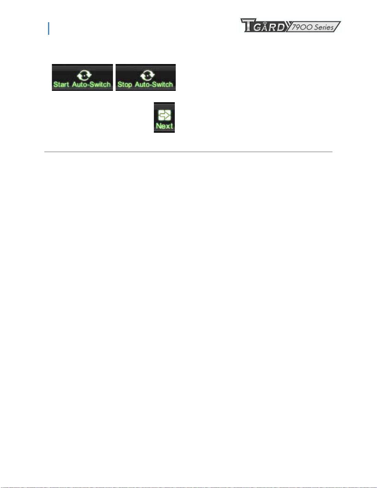
Start/Stop Auto-Switch: Click to start/ stop auto-switch.
Auto-switch will cycle through selected cameras. Switching of
camera can be on an individual or multiple camera basis.
Next Set of Display: Click to view the next set of display. In
2x2 mode, this will show the next four display. In 3x3 mode,
this will show the next nine display.
Note: In order to use auto-switching of channels, the dwell time must be configured in the Display Configuration menu.
Note: After 20 seconds of inactivity, the DVR will automatically exit out of the Display menu and go back into the Live
Feed mode.
Note: The Lock Main Menu setting is selected by default, meaning the Admin password must be enter to exit out of the
Live Feed into the Main Menu. To change this option and remove the lock to the Main Menu, visit the Lock Menus menu
(See Locking and Unlocking System Menus on page 59).
16
Page 17
PS-7900 Series User Manual
2.3 Configuring Live Feed Displays
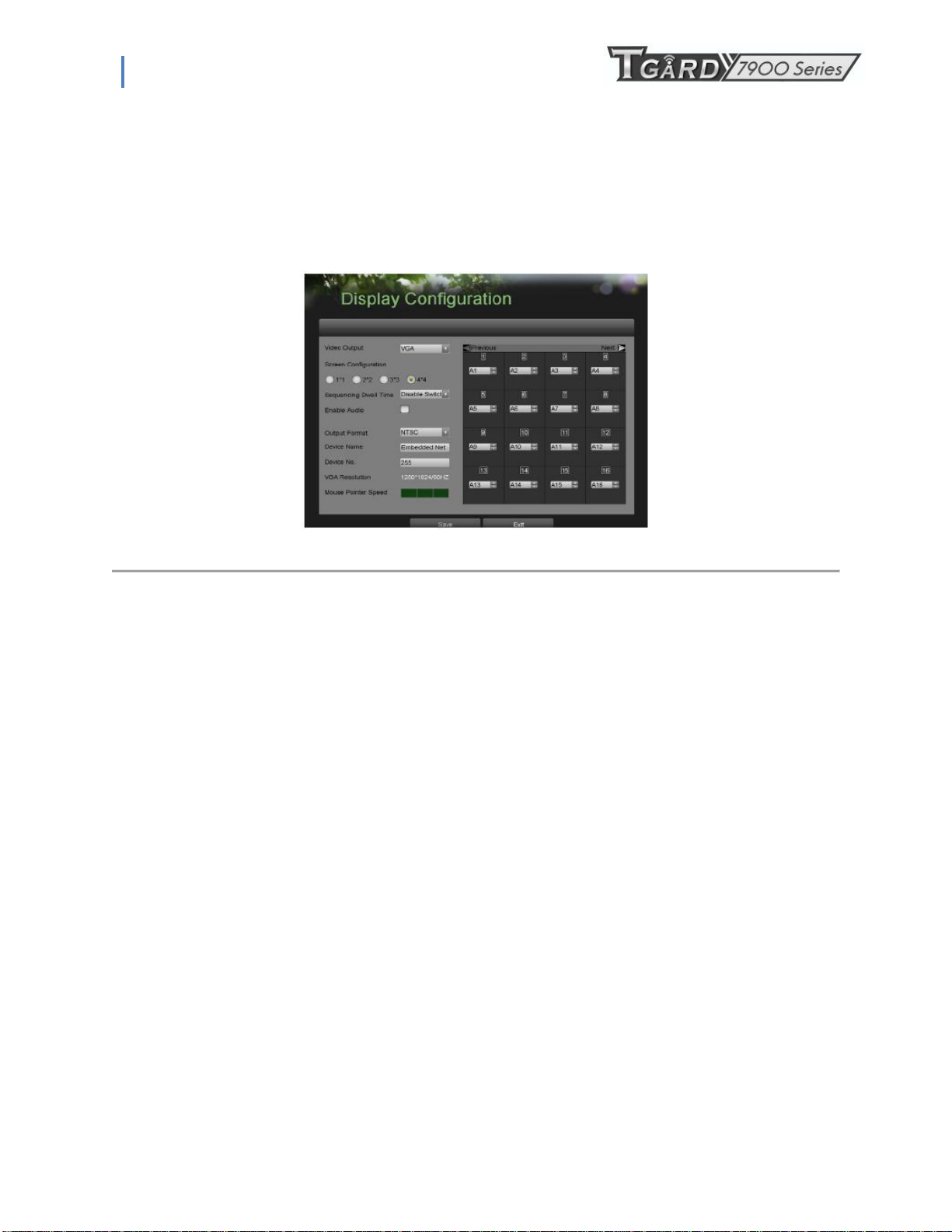
Live Feed displays can be customized to your own needs. These settings can be accessed by entering the Display
Configuration menu, shown in Figure 21.
To customize display settings:
1. Enter the Display Configuration menu by going to Main Menu > System Configuration > Display
Configuration.
2. Select the Video Output to configure. You may configure either the VGA, Main CVBS or Spot CVBS.
3. The settings available to configure for each video output includes:
Screen Configuration: Screen configuration of each video output. You may select between a 1x1,
2x2 or 4x4 configuration.
Sequencing Dwell Time: The time in seconds to dwell between switching of channels when Start
Sequence is selected in Live Feed. Selecting Disable Switching will disable switching in Live Feed.
Enable Audio: Enables/disables audio output for the selected video output.
Output Format: Designates the video output standard.
Device Name/No.: Designates the device name and number of the current unit.
VGA Resolution: Designates the resolution of main VGA display.
Mouse Pointer Speed: Pointer speed of the mouse, the higher the amount, the faster the mouse
would move.
Figure 21. Display Configuration Menu
17
Page 18
PS-7900 Series User Manual
2.4 Setting Camera Order
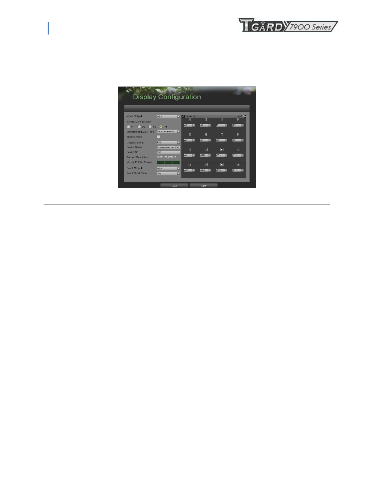
Setting the camera order allows you to logically position cameras for more efficient monitoring of your own individual
location.
Figure 22. Camera Order Setting
To set the camera order:
1. Enter the Display Configuration menu, shown in Figure 20 by going to Main Menu > System Configuration > Display
Configuration.
2. Select the Video Output to configure camera order for.
3. Select the Screen Configuration you would like to use in Live Feed. The preview of the screen configuration on the
right will change depending on the option selected.
4. Each display in the preview of the screen configuration will have a selection box containing a list of the different
cameras that are available on the DVR.
1. Pressing the up and down button of each selection box, select the camera you would like to show in the particular
display. Selecting „X‟ will disable the display.
5. Click the Previous and Next button to go to the next set of displays for the selected screen configuration. For example,
in 2x2 screen configuration mode, pressing the Next button will bring up the next set of 4 displays.
6. Click the Save button to Save settings.
7. Repeat steps 2-6 to adjust the camera order for other video outputs.
8. Click the Exit button to exit out of the menu.
Note: You must click the Save button after adjusting the order of one video output before you are able to move on to
adjust another one.
18
Page 19
PS-7900 Series User Manual
C H A P T E R 3
Record Settings
3.1 Configuring Settings for Recording
There are multiple ways to setup your DVR for recording. They include setting up a recording schedule, triggering a
recording by motion detection and/or a sensor alarm, and manually starting the recording.
3.1.1 Configuring Recording Settings
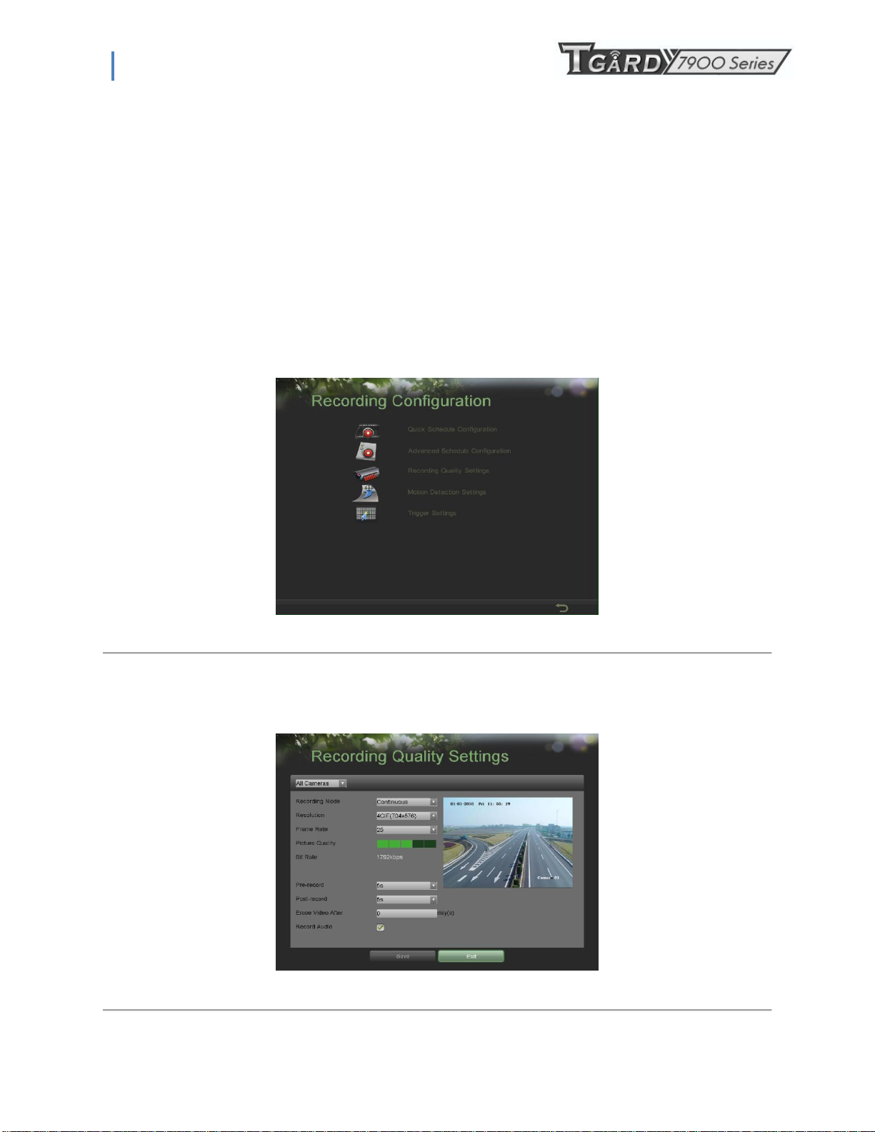
Before setting your DVR up for recording, certain settings should be configured first. These settings can be found in the
Recording Configuration menu, shown in Figure 23.
Figure 23. Recording Configuration Menu
The first set of settings to configure in this menu is the recording quality settings. To configure the recording quality settings:
1. Enter the Recording Quality Settings menu by going to Main Menu > Recording Configuration > Recording Quality
Settings. The Recording Quality Settings menu is shown in Figure 24.
Figure 24. Recording Quality Settings Menu
19
Page 20
PS-7900 Series User Manual
2. Select the camera to configure in the camera drop down menu on the upper left of the menu. If all cameras are to be
configured with the same settings, select All Cameras from the list.
3. Select the Encoding Parameters mode to configure. Either Continuous or On Event can be selected.
4. Select the camera resolution in the Resolution drop down menu The options for the camera resolution includes
4CIF,CIF and QCIF.
5. Select the recording Frame Rate to use for the designated camera. A rate of 25 all the way down to 1of a frame can be
selected.
6. Set the picture quality using the Picture Quality slider. A preview of the selected picture quality will be shown on the
right preview screen. Increasing the picture quality will also increase the bit rate of the video feed. The resolution and
frame rate of the feed will be adjusted automatically.
7. Select the Pre-record time. The pre-record time is the time in seconds to also record before a recording is triggered.
Setting the pre-record time to MAX will allow the DVR to use up to the maximum available buffer space for recording.
8. Select the Post-record time. The post-record time is the time in seconds to also record after a recording has ended.
9. Enter the Files Removed After time. The Files Removed After time denotes the amount of days that files will be
deleted after its initial recording. Setting the time to 0 will allow the DVR to only delete and overwrite files when the
HDD is full.
10. Repeat steps 3-9 for other Encoding Parameters mode.
11. Select the Save button to save the recording quality settings and select Exit to return to the previous menu. Selecting
the Exit button without clicking Save will quit out of the menu without saving settings.
Note: When resolution is 4CIF,Frame rate can only be set as 12 all the way down to 1.
3.1.2 Configuring a Quick Recording Schedule
A quick recording schedule allows you to set one time period per day for recording.
To setup a quick recording schedule:
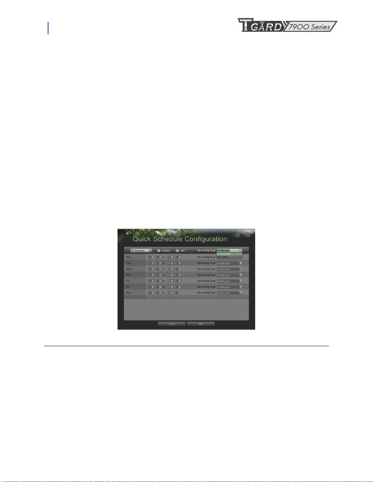
1. Enter the Quick Schedule Configuration menu, shown in Figure 25 by going to Main Menu > Recording
Configuration > Quick Schedule Configuration.
2. Select the camera to configure from the camera drop down menu. If all the cameras are to be configured with the
same settings, select All Cameras from the list.
3. Check the Enable checkbox to enable the recording schedule. If the checkbox is unchecked, the recording
schedule will be disabled.
4. Check the 24/7 checkbox if you would like to record continuously or on event for 24 hours a day, 7 days a week.
If you wish to schedule different time frames for Monday through Sunday, leave the 24/7 checkbox unchecked
and skip to step 6.
5. Select Recording Type for 24/7 recording and move on to step 8. Recording type includes Continuous for
continuous recording or On Event for recording when an event is triggered (i.e. from detected motion).
6. Select the start and stop time for each day of the week. The start and stop time are listed using a 24 hr cycle (i.e.
18:00 is equivalent to 6:00pm).
7. Select Recording Type for each day of the week. Recording type includes Continuous for continuous recording or
On Event for recording when an event is triggered (i.e. from detected motion) for the selected time period.
Figure 25. Quick Schedule Configuration Menu
20
Page 21
PS-7900 Series User Manual
8. Select the Save button to save the schedule settings and select Exit to return to the previous menu. Select the
Exit button without clicking Save will quit out of the menu without saving settings.
Note: On Event recordings are recordings that are triggered from motion detection and/ or from an external alarm (See
Configuring Alarms and Exceptions on page 61).
Note: If an event occurs during Continuous recording, the frame rate will automatically switch to that set for Event recording.
3.1.3 Configuring an Advanced Recording Schedule
An advanced recording schedule allows you to schedule multiple time periods per day for recording as oppose to a single time
period of a quick recording schedule. Setting up an advanced recording schedule will allow you to further conserve disk space by
recording only during the time periods you would like to record at.
To setup an advanced recording schedule:
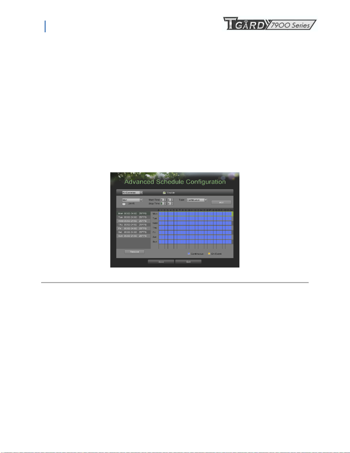
1. Enter the Advanced Schedule Configuration menu, shown in Figure 26 by going to Main Menu > Recording
Configuration > Advanced Schedule Configuration.
Figure 26. Advanced Schedule Configuration Menu
2. Select the camera to configure from the camera drop down menu. If all the cameras are to be configured with the same
settings, select All Cameras from the list.
3. Check the Enable checkbox to enable the recording schedule. If the checkbox is unchecked, the recording schedule
will be disabled.
4. Select a day between Monday to Sunday to configure schedule for.
5. Setup time periods for schedule. If the 24HR checkbox is checked, recording will occur over the entire day. To setup
multiple time periods, uncheck 24HR and enter the Start and Stop Time for the selected day. The start and stop time
are listed using a 24 hr cycle (i.e. 18:00 is equivalent to 6:00pm).
6. Select recording type under Type for selected day of the week. Recording type includes Continuous for continuous
recording or On Event for recording when an event is triggered (i.e. from detected motion) for the selected time period.
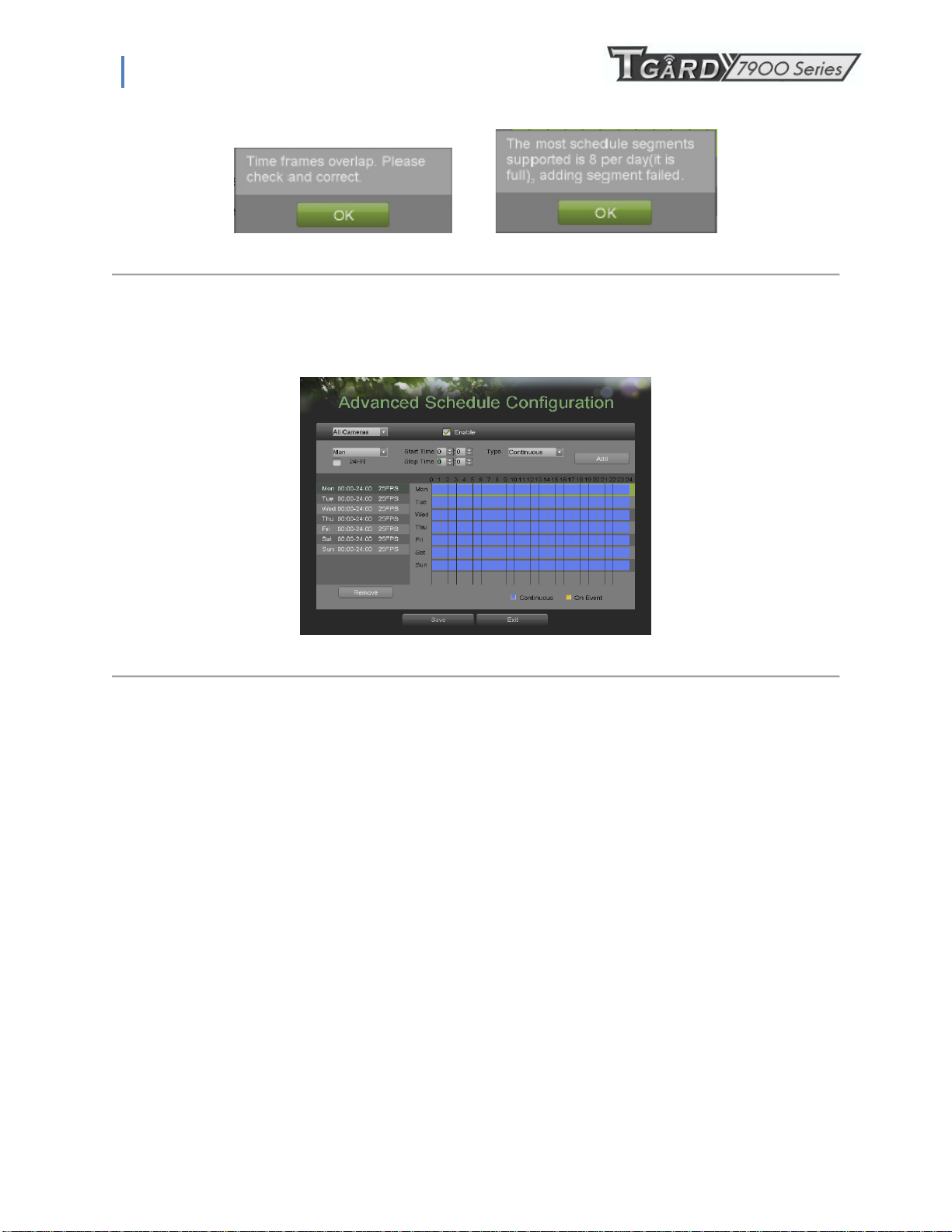
7. If there are scheduling errors detected, such as overlapping time periods, error messages such as those shown in Figure
25 will appear.
21
Page 22
PS-7900 Series User Manual
Figure 27. Advanced Schedule Configuration Error Messages
8. Select the Add button to add time frame to schedule. The newly added time frame will appear in the schedule on
the left, with the schedule parameters shown on the right. Continuous recordings are shown in blue on the
schedule while event recordings are shown in yellow. An example of this can be seen in Figure 28.
Figure 28. Advanced Schedule Configuration Example
9. Repeat steps 4-10 to setup additional time periods for the selected day.
10. Select the Save button to save the schedule settings and select Exit to return to the previous menu. Selecting the
Exit button without clicking Save will quit out of the menu without saving settings.
Note: Creating a schedule in the Quick Schedule Configuration menu will also create a schedule in Advanced Schedule
Configuration. The quick schedule will show up as a time period in the Advanced Schedule Configuration.
22
Page 23
PS-7900 Series User Manual
C H A P T E R 4
Playback
4.1 Playing Back a Recording
Previously recorded files can be played back using the Playback Interface. You must first search for recordings to play
them back.
4.1.1 Understanding the Playback Interface
It’s important to understand how to use the Playback Interface to efficiently navigate through recorded files. To access the
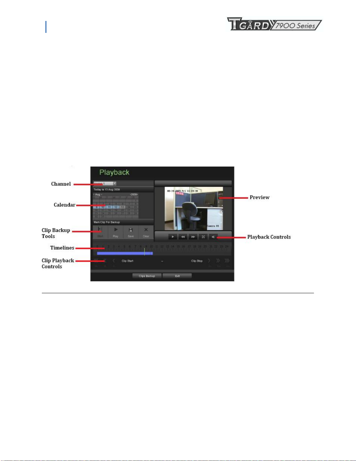
Playback Interface, shown in Figure 29, go to Main Menu > Playback.
Figure 29. Playback Interface Menu
Some of the main features of the Playback Interface includes:
• Channel Selector: Select the channel to search for recordings on.
• Calendar: Select the date to search for recordings on.
• Timeline: Select the time to search for recordings on.
• Preview: Shows a preview of the selected recording.
• Playback Controls: Controls for playback of the selected recording.
• Clip Backup Tools: Tools to backup clips from a recording.
• Clip Playback Controls: Controls for playback of marked clip.
23
Page 24
PS-7900 Series User Manual
4.2 Searching for Recorded Files
The Playback Interface allows for easy searching of recorded files. To search for recorded files using the Playback
Interface:
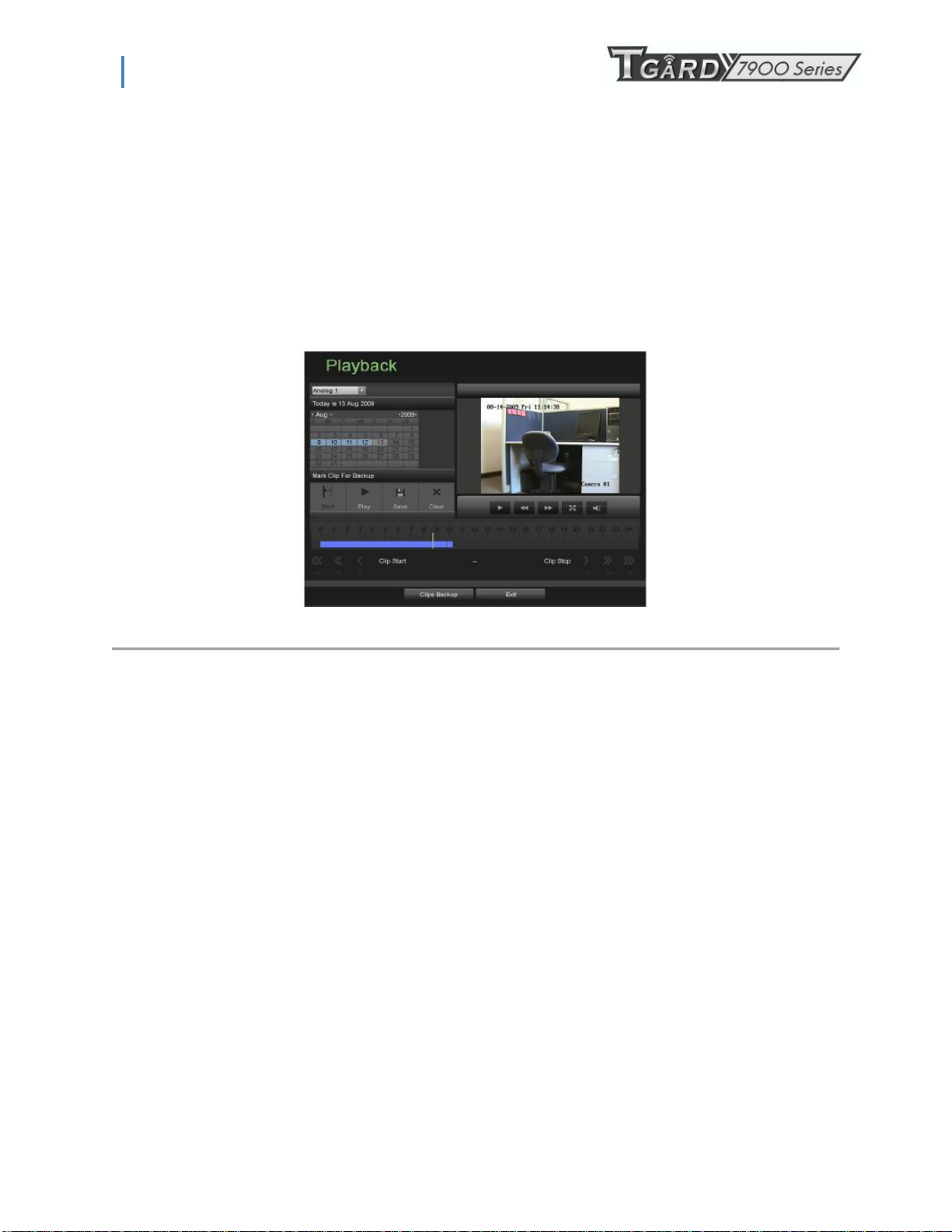
1. Enter the Playback menu, shown in Figure 28 by going to Main Menu > Playback.
2. Select the channel to search for recordings on.
3. Select the date to search for recordings on using the calendar. The system date is shown at the top of the
calendar. You may change the month and year of the calendar by clicking the left and right arrows next to the
month and year .Dates with continuous recordings in the selected month and channel are displayed in light blue,
and dates are displayed in yellow when they are on event recording. Dates without recordings are dark gray.
The active selected date is displayed in light gray, as shown in Figure 30.
Figure 30. Playback Menu Example
4. Click on the desired date that is highlighted in light blue to search for recordings. If recordings exist, the timeline
will be filled with blue bars to designate recorded files. The playback marker, indicated by a green vertical line
will automatically jump to the beginning of the earliest recordings for the selected date. The marker can be
moved to any other location by clicking on the desired position on the blue bars.
5. Select the Play button in the Playback Controls to start playback of the recording.
24
Page 25
PS-7900 Series User Manual
4.3 Playing Back Recorded Files
After finding the recordings you would like to playback (See Searching for Recorded Files on page 37), you may use the
Playback Controls to navigate through the recording.
The controls found under Playback Controls include:
Play Button: Button to playback recording.
Decrease Speed Button: Button to decrease play speed.
Increase Speed Button: Button to increase play speed
Enter/Exit Full-Screen Mode: Button to enter into and exit out of full-screen mode.
Enable/Disable Audio: Button to enable and disable audio in playback mode.
Figure 31. Playback control buttons
To playback recorded files:
1. Search and select recording to playback in the Playback Interface.
2. Click the Play button to begin playback of selected recording and the Pause button to pause playback.
3. You may slow down or speed up the playback speed by clicking the Decrease Speed/Increase Speed button.
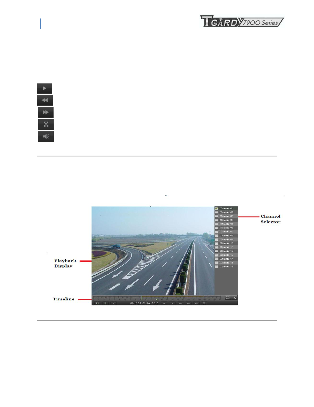
4. Click the Full-Screen button to enter full-screen playback mode, shown in Figure 32
5. In full-screen mode, you may hide the toolbars by clicking the Hide Toolbar button. Clicking the Exit Full-Screen
button will return you to the original playback mode.
6. Click the Enable/Disable Audio button to turn on and off audio during playback.
7. Click the Digital Zoom button to enable digital zoom. Once enabled, the regular recorded feed will be shown in
the lower right corner while the zoomed in view will be shown on the full screen. The zoomed in region may be
changed by moving the red rectangle in the regular recorded feed window.
8. Click the Exit button to return to the previous menu.
Figure 32. Full-Screen Playback Mode
25
Page 26
PS-7900 Series User Manual
4.4 Playing Back Multiple Channels
You may also playback recordings from multiple channels simultaneously. To playback recordings from multiple
channels:
1. Search and select recording to playback in the Playback Interface.
2. Enter into Full-Screen mode, shown in Figure 30 by clicking the Full-Screen button.
3. In Full-Screen mode, you may select additional channels to playback by clicking the checkbox next to the desired
camera in the Channel Selector panel. Playback will begin simultaneously on the selected channels.
4. You may stop playback on any of the channels by un-checking the checkbox next to the channel.
Note: Up to4 channels can be played back at the same time.
C H A P T E R 5
Backup
5.1 Backing Up Video Clips
Video clips can be backed up to various devices, such as USB flash drives, USB HDDs or a DVD writer.
5.1.1 Selecting Video Clips
Video clips can be selected for backup in the Playback Interface using the controls found in the Mark Clip For Backup
panel, shown in Figure 33.
Figure 33. Mark Clip For Backup Controls
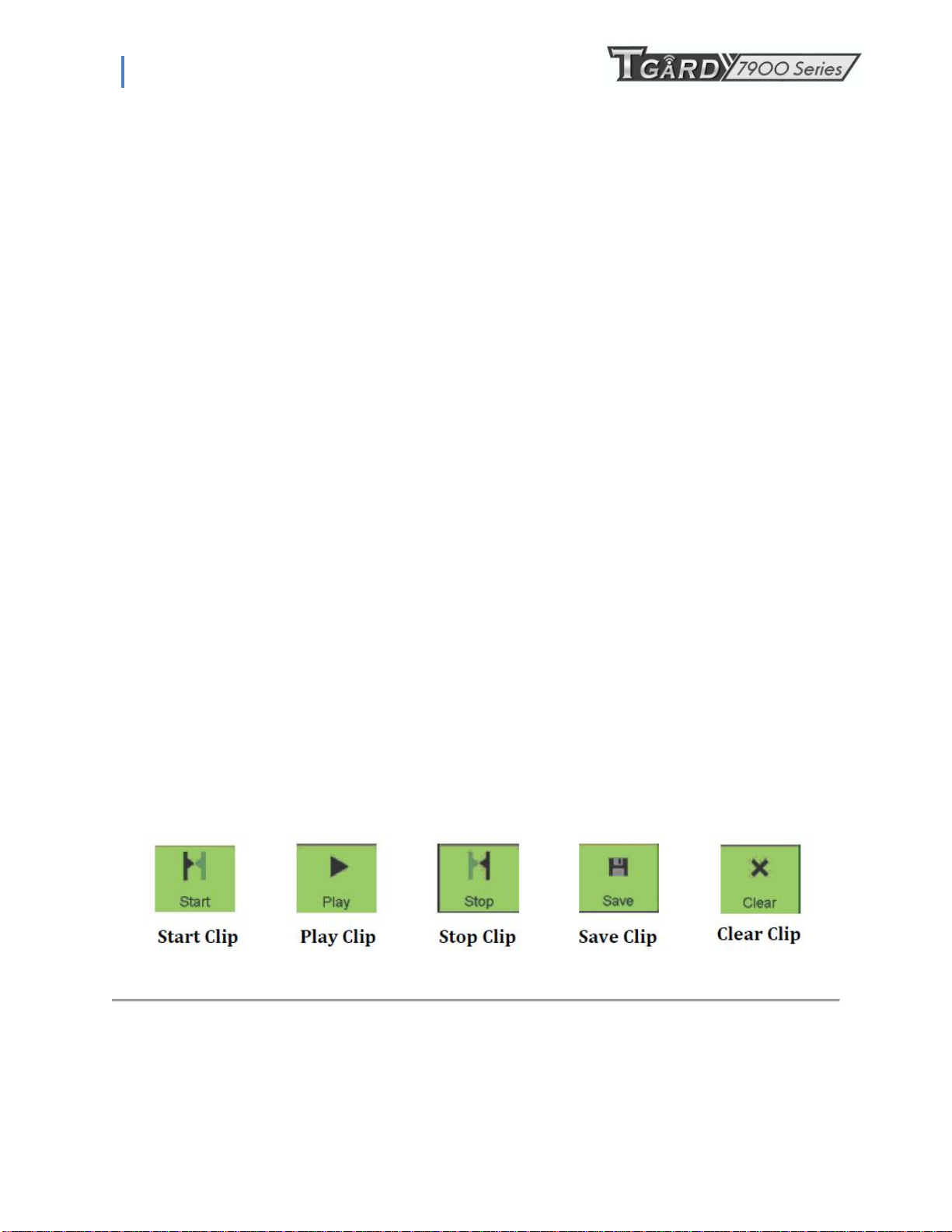
The controls found in the Mark Clip For Backup panel includes:
• Start Clip Button: Mark the starting point for the video clip.
• Stop Clip Button: Mark the ending point for the video clip.
• Play Clip Button: Play the selected video clip.
• Save Clip Button: Save the selected video clip to the HDD.
26
Page 27

PS-7900 Series User Manual
• Clear Clip Button: Clear the selected video clip.
27
Page 28
PS-7900 Series User Manual
To select video clips in the Playback Interface:
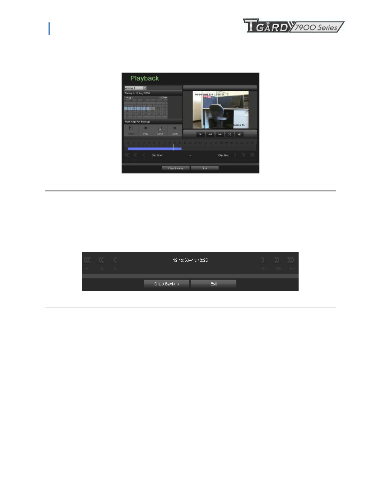
1. Enter the Playback Interface, shown in Figure 34 by going to Main Menu > Playback.
Figure 34. Playback Menu
2. Search for the recorded files that you would like to select video clips from (See Searching for Recorded Files on
page 35). Video clips can only be selected in single playback mode.
3. Select the starting position of the video clip by clicking the desired location on the blue recordings bar.
4. Click the Start Clip button.
5. Select the ending position of the video clip.
6. Click the stop Clip button.
7. The selected video clip time range will be shown at the bottom of the Playback Interface, as seen in Figure 35.
Figure 35. Video Clip Time Range
8. You may play the video clip using the Play Clip button or use the arrow keys shown next to the clip time range to
progress through the video one second, minute or hour at a time.
9. Click the Save Clip button to save clip to the DVR. Clip must be first saved to the DVR before it can be backed up
to an external USB storage device or to a DVD writer. Clicking the Clear Clip button will remove the video clip.
10. Repeat steps 2-7 to select additional clips. If you would like to backup video clips at this point, click the Backup
button.
Note: The Play Clip, Save Clip and Clear Clip buttons are not available unless a completed video clip is selected. A
completed video clip has a start and end point marked by using the Start Clip and End Clip button.
Note: The Start Clip button is not available when there is still a video clip that has not been saved or cleared.
5.2 Backing Up Video Clips
After video clips have been selected in the Playback Interface (See Selecting Video Clips on page 46), you may back them
up to an external USB storage device or DVD writer by going to the Backup menu.
To backup video clips:
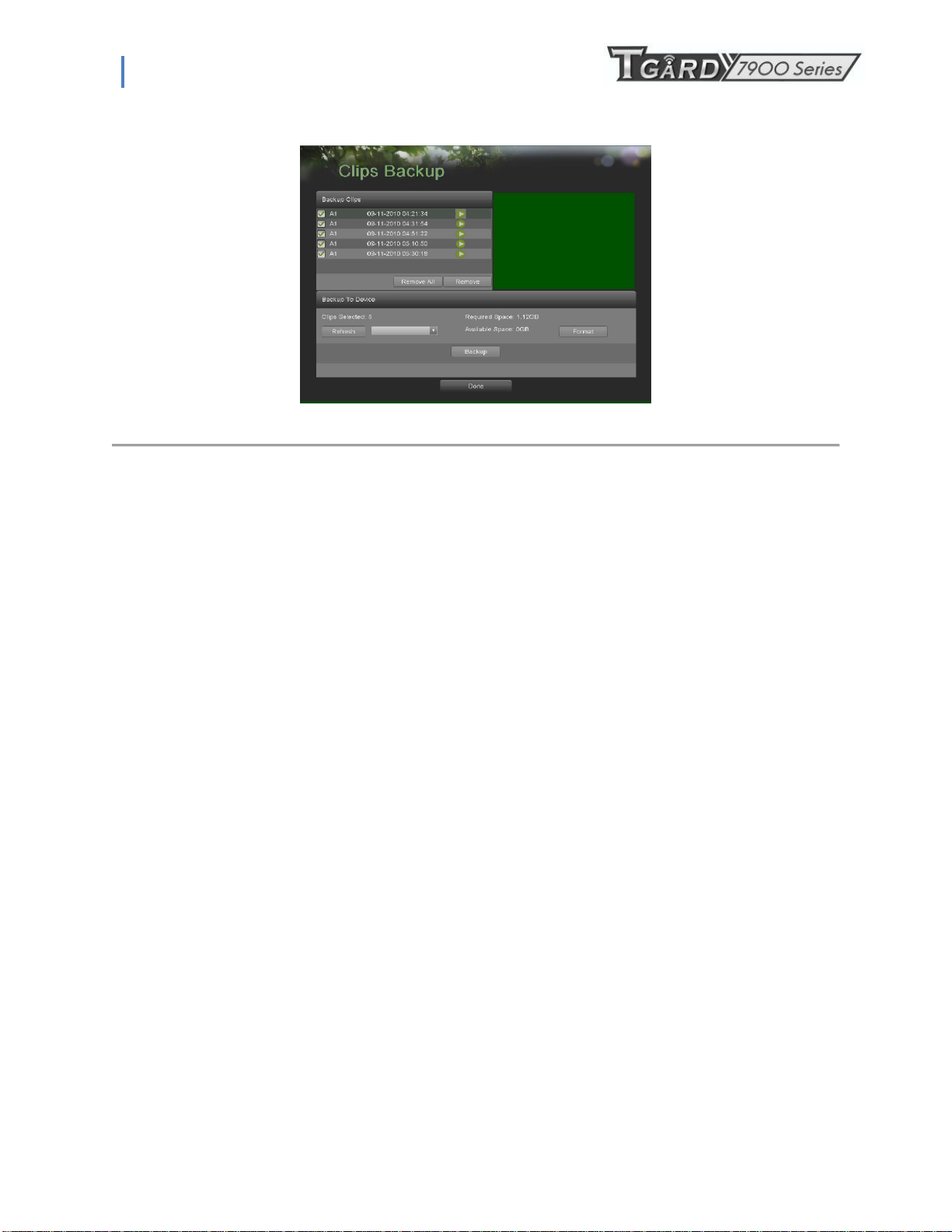
1. Enter the Clips Backup menu, shown in Figure 36 by first going to Main Menu > Playback. In the Playback menu,
click the Clips Backup button.
28
Page 29
PS-7900 Series User Manual
Figure 36. Clips Backup Menu
2. If video clips were successfully saved to the HDD using the Playback Interface, they will be listed under the
Backup Clips heading on the left hand side of the menu. The camera number as well as the time range would be
listed.
3. Select the video clips you would like to backup by checking the checkbox next to the desired clips. You may also
click the Play icon to play and review the clip. Video clips can be deleted by selecting it and clicking the Remove
button or by clicking the Remove All button to delete all clips.
4. Connect at least one USB storage device to the DVR. If the device is compatible with the DVR, it will
automatically be detected. Select the backup device from the Backup Device drop down menu.
5. The Clips Selected, Required Space and Available Space will be displayed on the Clips Backup menu. If the USB
storage device has not been properly initialized and formatted, you may click on the Format button to do so. It is
important to note that formatting will delete ALL data from the storage device.
6. If the available space on the storage device is adequate, select the Backup button to begin backup of the selected
clips.
7. After clips have been backed up, you may click the Playback button to return to the Playback Interface or the
Done button to return to the previous menu.
Note: Formatting a storage device will permanently delete all the files on that device.
There is also NO WARNING MESSAGE after clicking the Format button to format the storage device. Please proceed with
caution and backup all critical data from the storage device before formatting.
5.3 Backing Up Recorded Files
Not only can video clips be backed up, full recorded files can also be backed up to a storage medium.
To back up recorded files:
1. Search for recorded files using the File Management menu (See Searching for Recorded Files on page 83).
2. Select the files you would like to backup by checking the box next to the file. You may also check the All File box
to backup all files. The total required space will be shown next to Total Size.
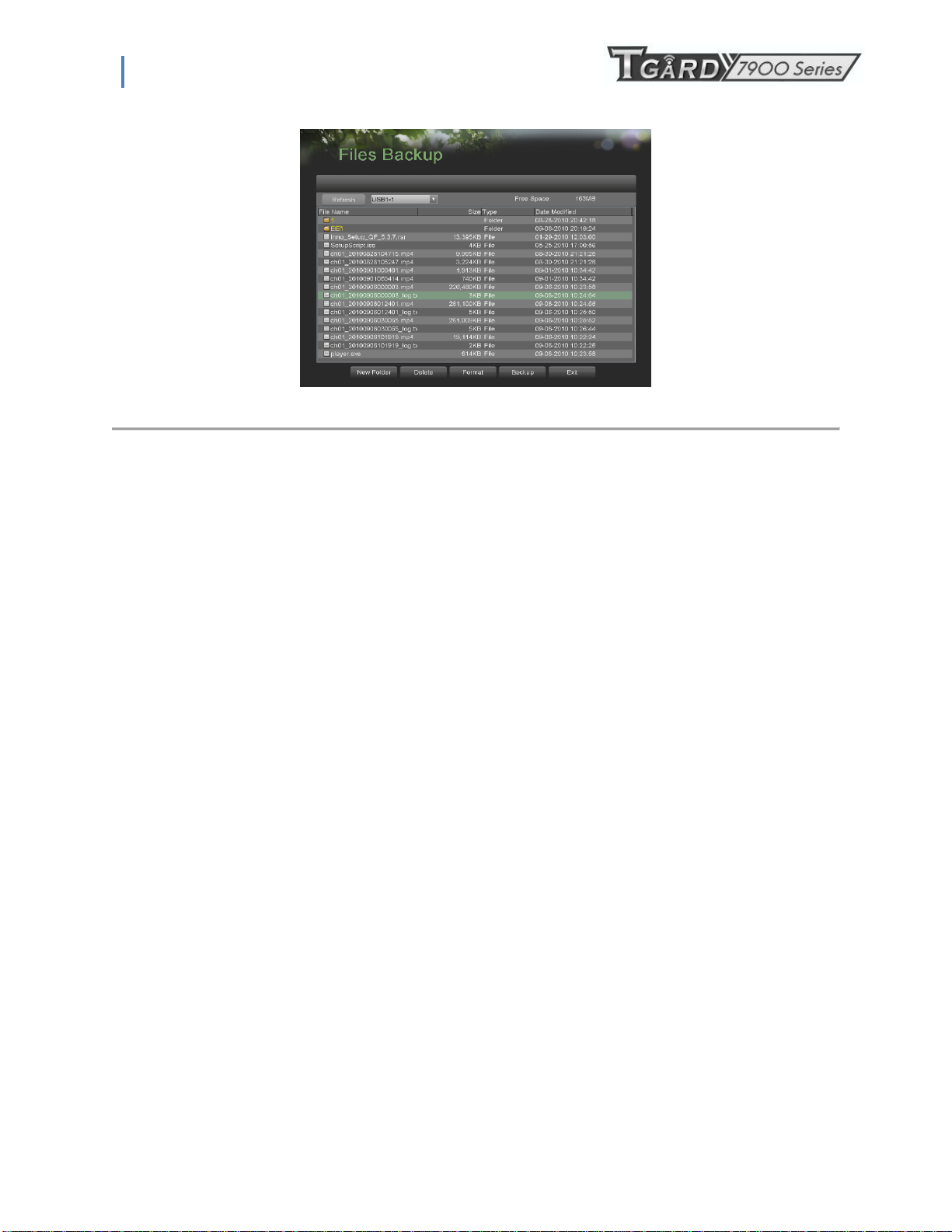
3. Click the Files Backup button, this will take you to the Files Backup menu, as shown in Figure 37.
29
Page 30
PS-7900 Series User Manual
Figure 37. Files Backup Menu
4. In the Files Backup menu, connect a USB storage device and click the Refresh button. If the device is detected, a list of
its file contents as well as the available free space will be shown.
5. You may delete files on the USB storage device to free up additional storage space by clicking the Delete button on the
selected file. You may also format the device by clicking the Format button. Formatting will remove ALL files from the
device.
6. When there is sufficient storage space for backup, click the Backup button. A backup progress bar will be shown.
7. Click the OK button once backup has completed.
8. Click the Exit button to return to the File Management menu.
30
Page 31
PS-7900 Series User Manual
C H A P T E R 6
System Configuration
6.1 Configuring Network Settings
6.1.1 Network configuration
Network settings must be configured before you’re able to use your DVR over the network.
To configure network settings:
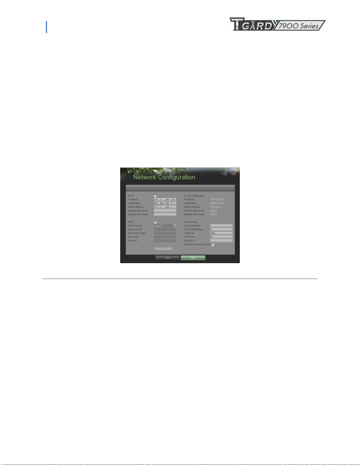
1. Enter the Network Configuration menu, shown in Figure 38 by going to Main Menu > System Configuration >
Network Configuration.
Figure 38. Network Settings Menu
2. The current network settings are displayed on the right side of the menu.
3. If you have a DHCP server running and would like your DVR to automatically obtain an IP address and other
network settings from that server, check the DHCP checkbox.
4. If you would like to configure your own settings, enter the settings for:
• IP Address: IP address you would like to use for your DVR.
• Subnet Mask: Subnet Mask of network.
• Default Gateway: IP address of your Gateway. Typically the IP address of your router.
• DNS Server: The preferred and alternate Domain Name System (DNS) Server to be used with your DVR.
5. To enable Dynamic DNS (DDNS), check the DDNS checkbox. Dynamic DNS allows you to create a hostname and
associate it to your IP address, making access to your DVR over the internet easier. To configure DDNS:
1. Enable DDNS by checking the DDNS checkbox.
2. Select a DDNS provider from the DDNS Provider selection box.
3. Enter settings for Server Address, DVR Domain Name, User Name, and Password.
6. If a central monitoring station that is compatible with your DVR is available, you may enter its settings under
Central Station IP and Central Station Port.
7. Enter the Client Port and HTTP Port to be use with your DVR. The client port designates the port to be use with
the client software while the HTTP port refers to the one to be use with the built-in Web Server.
8. After all settings have been configured; you may test the connection by clicking the Test Connection button. A
confirmation message, similar to the one shown in Figure 39 will pop up if the network is working properly.
31
Page 32

PS-7900 Series User Manual
Figure 39. Test Connection Confirmation
9. Select the Save button to save the network settings and select Exit to return to the previous menu. Selecting the
Exit button without clicking Save will quit out of the menu without saving settings.
6.1.2 Extended remote connection
Extended remote connection is used for adding more network visitors with sub stream. Check “Extended remote
connection” to enable this function.
7904-S support up to 24 network visitors, six for each channel.
7908-S support up to 48 network visitors.
7916-S support up to 50 networks visitors.
If you don’t enable this function, then 7908-S/7916-S only support up to 24 network visitors.
You have no need of checking “Extended remote connection” when it is 7904-S.
.
6.2 Managing User Accounts
By default, DVR comes with two user accounts, the Administrator account and the Guest accounts. The Administrator user
name is admin and the password is 12345. The default password for Administrator should be changed right away for
security reasons. The Administrator has the authority to add, delete or configure parameters for many of the system
functions. The Guest accounts user name is guest without password. You can easily switch between accounts by click
Login/Logout at the lower left corner of the main menu.
6.2.1 Adding a New Remote/Local User
You may add up to 30 new users to your DVR.
To add new users:
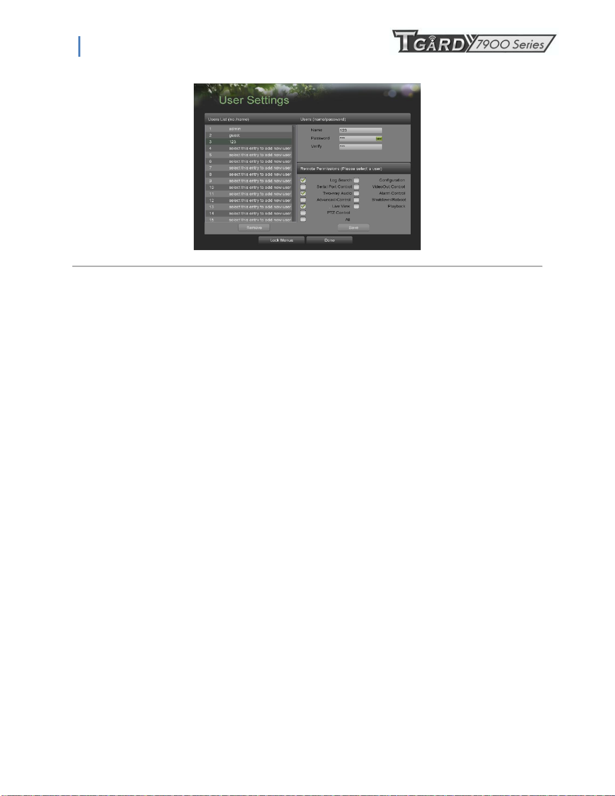
1. Enter the User Settings menu, shown in Figure 40 by going to Main Menu > System Configuration > User
Settings.
32
Page 33
PS-7900 Series User Manual
Figure 40. Remote User Settings Menu
2. Under Users List, click on Select this entry to add new user.
3. Once a new entry has been selected, the fields under Users will become editable. Enter the information for Name,
Password and Verify.
4. In the Remote Permissions panel, select the functions that you would like to give the user access to remotely. You
may also check the All checkbox to give full control to the selected remote user. These functions include:
• Log Search: View logs that are saved on the DVR.
• Serial Port Control: Configure settings for RS232 and RS485 ports.
• Two-Way Audio: Ability to use two-way radio between the remote client and the DVR.
• Advanced Control: Manage hard disk drives (initializing and setting properties for HDDs). Ability to remote
update system firmware and stopping of the relay output.
• Live View: Access the Live Feed.
• PTZ Control: Control PTZ cameras.
• Configuration: Configure parameters, restore parameters to factory defaults and import settings to as well as
export settings from DVR.
• Video Output Control: Configure settings for video output.
• Alarm Control: Alert or control the relay output of the DVR. Alarm and exception settings must be configured
properly to upload to host.
• Shutdown/Reboot: Shutdown or reboot the DVR.
• Playback: Playback recordings remotely.
• All: Full permission to use all functions.
5. Click the Save button to save user settings and click Done to return to the previous menu.
Note: Users both have the local access permission and the remote access permission.
Note: Lock menus configuration is to allow local users entering or not entering menus.(Details see page 60 )
You can go to Lock Menus menu easily by clicking the‟ Lock menus‟ button on the bottom of the User setting menu.
Note: If you forget the password to your DVR, contact your supplier with the serial number of your DVR to obtain a secure
code to reset your DVR.
Note: User settings only appear on the list of System Configuration when login with Administrator accounts.
6.2.2 Deleting a User
To delete a user from the DVR:
1. Enter the User Settings menu, shown in Figure 39 by going to Main Menu > System Configuration > User Settings.
2. Select a user to delete in the Users List panel.
3. Click the Remove button to delete user.
33
Page 34
PS-7900 Series User Manual
4. Click the OK button to confirm deletion of user.
5. Click the Done button to exit menu.
6.2.3 Editing a User
To edit a user:
1. Enter the User Settings menu, shown in Figure 39 by going to Main Menu > System Configuration > User Settings
2. Select a user to edit in the Users List panel.
3. Edit user information in the Users and Remote Permissions panel. Remote permissions are defined above in Adding a
New Remote User on page 54.
4. Click Save button to save settings and Done button to exit menu.
Note: Password of Administrator can be modified in User setting menu. If password of administrator is changed, a dialog box
to enter in the older password will appear after clicking save button, enter in the right password and click Done button to exit.
Note: User password can be both numbers and characters. You can click the button on the password editable fields to
enter characters.
6.2.4 Switch User
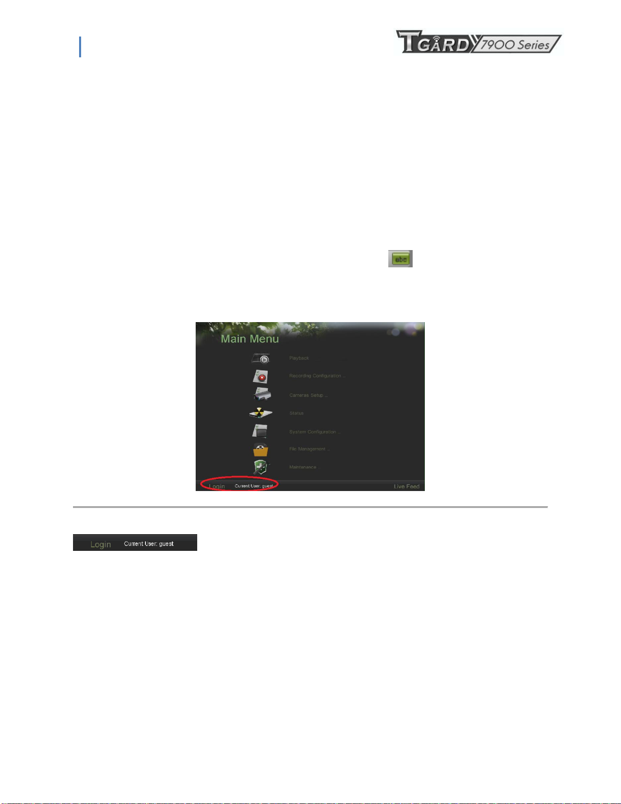
Figure 41. Main Menu
On the main menu (see in Figure 41), information about users are show on the lower left corner,
, click Login/Logout to switch users.
6.3 Configuring PTZ Cameras
34
Page 35
PS-7900 Series User Manual
6.3.1 Configuring Basic PTZ Settings
Settings for a PTZ camera must be configured before it can be used. Before proceeding, verify that the PTZ and RS-485 of the
DVR are connected properly.
To configure PTZ settings:
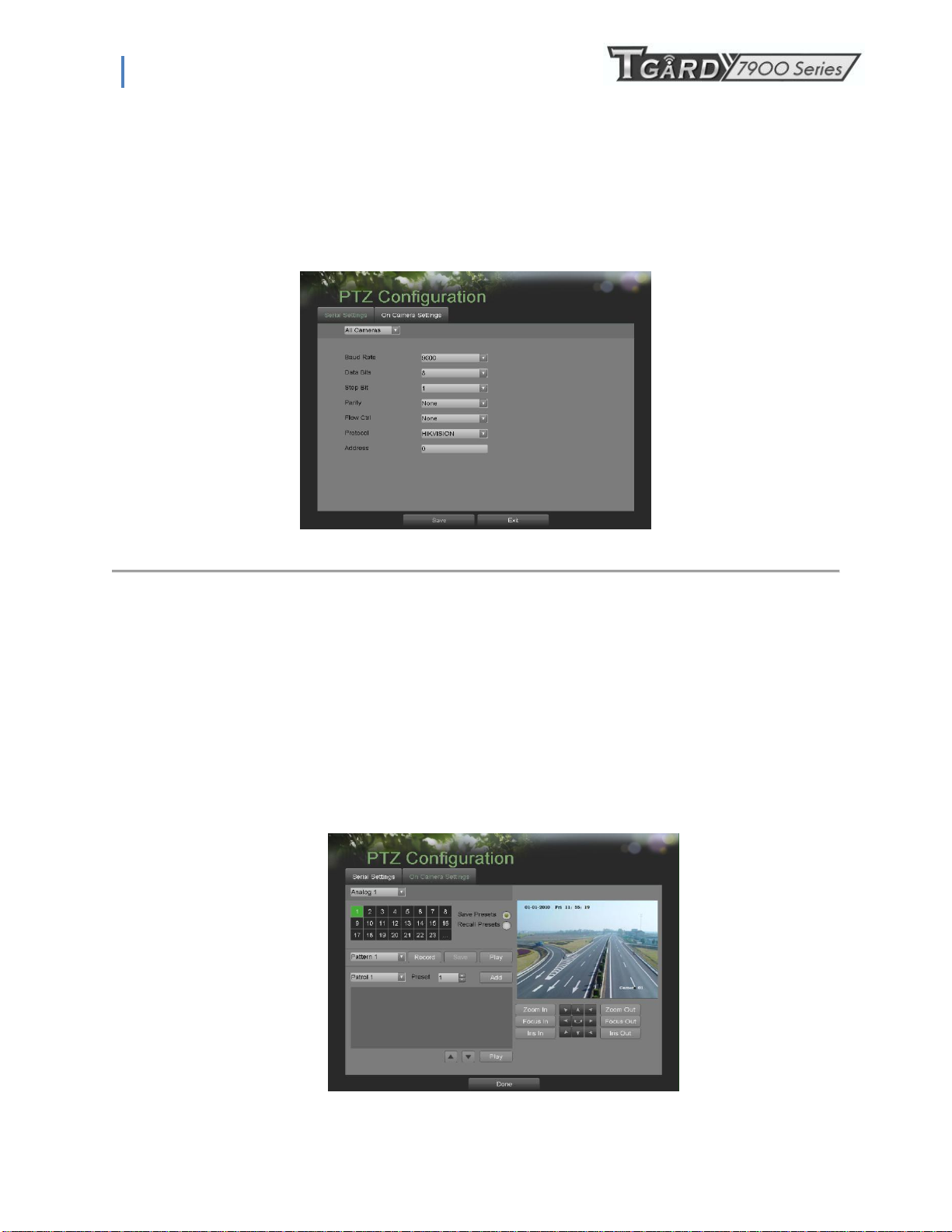
1. Enter the PTZ Configuration menu, shown in Figure 42 by going to Main Menu > System Configuration > PTZ
Configuration.
Figure 42. PTZ Configuration Menu
2. Select the Serial Settings tab.
3. Select the camera to configure in the camera drop down menu on the upper left of the menu. If all cameras are to be
configured with the same settings, select All Cameras from the list.
4. Configure PTZ settings, including those of Baud Rate, Data Bit, Stop Bit, Parity, Flow Ctrl, Protocol and Address
according to the parameters of the PTZ camera(s).
5. Click the Save button to save current settings.
To test and verify PTZ settings:
1. Enter the PTZ Configuration menu, shown in Figure 41 by going to Main Menu > System Configuration > PTZ
Configuration.
2. Select the On Camera Settings tab. This will open up the On Camera Settings menu, shown in Figure 43.
35
Page 36
PS-7900 Series User Manual
Figure 43. PTZ Configuration
3. Select the camera to test in the camera drop down menu.
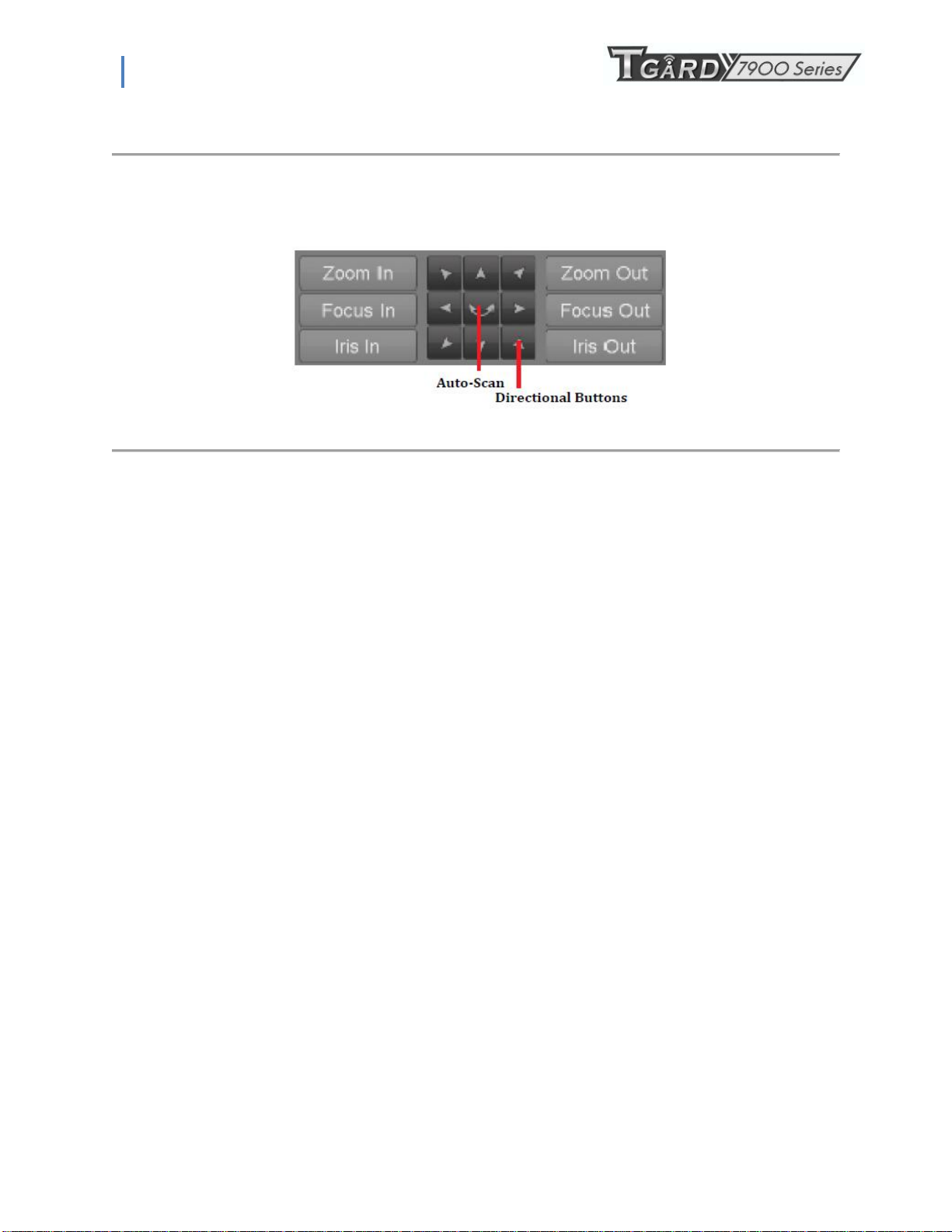
4. Using the Directional buttons and other PTZ control buttons (Zoom In/Out, Focus In/Out, Iris In/Out), test the
functionality of the PTZ camera. If PTZ camera and protocol supports it, you may also click the Auto-Scan button to
test its function. PTZ controls buttons are shown in Figure 44.
Figure 44. PTZ Controls Button
5. If PTZ camera is not working properly, make sure PTZ is connected and configured with the correct settings under the
Serial Settings tab.
6. Click Done to exit and return to the previous menu.
6.4 Customizing PTZ Presets, Patterns and Patrols
Your DVR allows you to customize presets, patterns and patrols for a connected PTZ ,camera. A PTZ camera must first be
configured before PTZ presets, patterns and patrols can be customized (See Configuring Basic PTZ Settings on page 57).
To customize PTZ presets:
1. Enter the PTZ Configuration menu, shown in Figure 42 by going to Main Menu > System Configuration > PTZ
Configuration.
2. Select the On Camera Settings tab.
3. Select Save Presets and move the camera to the desired position using the PTZ control buttons.
4. Double-click on a preset number in the upper left corner of the screen. The current position of the PTZ camera will be
set for the selected preset number.
5. To test the newly configured preset, first move the PTZ camera to a different position. Select Recall Presets and click
on the preset number. The camera should move to the location that was set for the selected preset number.
6. Click the Done button to exit out of the PTZ Configuration menu.
Note: Only the first 23 presets are shown in the table. To save or recall more presets, click on the “...” button. Clicking the “...”
button will bring up a selection list for presets up to 200.
To customize PTZ patterns:
1. Enter the PTZ Configuration menu, shown in Figure 42 by going to Main Menu > System Configuration > PTZ
Configuration.
2. Select the On Camera Settings tab.
3. Select a Pattern Number to set from the drop down list.
4. Click the Record button to begin recording the movement of the PTZ.
5. Move the PTZ to the desired locations using the PTZ control buttons.
6. Click the Save button to save pattern.
7. To test out your new pattern, click the Play button. The PTZ should move as it did during the recording process. You
may click the Stop button at any time to end the pattern. Clicking the Play button again will start playing the PTZ
pattern again at the initial position.
8. Click the Done button to exit out of the PTZ Configuration menu.
36
Page 37
PS-7900 Series User Manual
To customize PTZ patrols:
1. Enter the PTZ Configuration menu, shown in Figure 42 by going to Main Menu > System Configuration > PTZ
Configuration.
2. Select the On Camera Settings tab.
3. Select a Patrol Number to set from the drop down list.
4. Select a Preset Number that is next to the Patrol Number from the drop down list that you would like to add to the
patrol.
5. Click the Add button. The Preset Number will be added to the patrol list.
6. Repeat steps 4-5 until you have included all the presets you would like to have on the patrol.
7. Click the Up and Down button at the bottom of the list to change the order of the presets in the patrol.
8. To test out your new preset, click the Play button. The PTZ should move through the list of added presets.
9. Click the Done button to exit out of the PTZ Configuration menu.
6.5 Configuring Alarms and Exceptions
6.5.1 Setting Up Motion Detection
Set up properly, using motion detected recording will increase the number of days your DVR is able to record. It will only record
relevant events rather than everything, which will also make searching for events easier.
To set up motion detection:
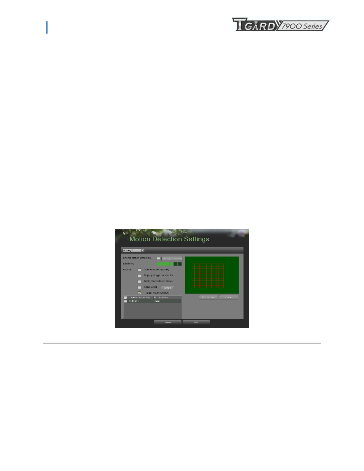
1. Enter the Motion Detection Settings menu, shown in Figure 45 by going to Main Menu > Recording Configuration > Motion
Detection Settings.
2. Select the camera to configure in the camera drop down menu on the upper left of the menu. If all cameras are to be configured
with the same settings, select All Cameras from the list.
3. Check the Enable Motion Detection checkbox to enable motion detection for the selected camera. Uncheck the checkbox to
disable motion detection.
4. Set the motion detection sensitivity by adjusting the green Sensitivity bar. The more lime green rectangles selected in the bar,
the higher the sensitivity will be to motion.
5. Set the motion detection region in the preview screen on the right side of the menu by left-clicking with the mouse on an open
area. A red grid will be shown, designating that the selected area is part of the motion detection region. Dragging or left-clicking
on areas that overlap the current selected motion detection area will include them into the region. You may also click the Full
Screen button to include the whole area into the motion detection region. Left-clicking on any part of the grid will remove that
section from the motion detection region.
6. If you‟re not satisfied with the selected region, you may click the Clear button to reset the motion detection area.
Figure 45. Motion Detection Settings Menu
37
Page 38
PS-7900 Series User Manual
7. Select the Actions to take if motion is detected in the designated regions. More than one action can be selected. The actions
available includes:
• Sound Audio Warning: DVR will sound an audio warning if motion is detected in the designated regions of the
camera.
• Pop-up Image on Monitor: DVR will show an image of what caused the motion on the monitor.
• Notify Surveillance Center: DVR will notify surveillance center when motion is detected.
• Send Email: DVR will send an email out to the designated recipients when motion is detected.
• Trigger Alarm Output: DVR will trigger alarm output when motion is detected. Selecting this option will enable
the Alarm Output list, where the output to trigger can be selected.
8. Select the Save button to save the motion detection settings and select Exit to return to the previous menu. Selecting the
Exit button without clicking Save will quit out of the menu without saving settings.
6.5.2 Configuring Exceptions
Actions can also be triggered when the DVR detects certain exceptions. To setup exception configuration:
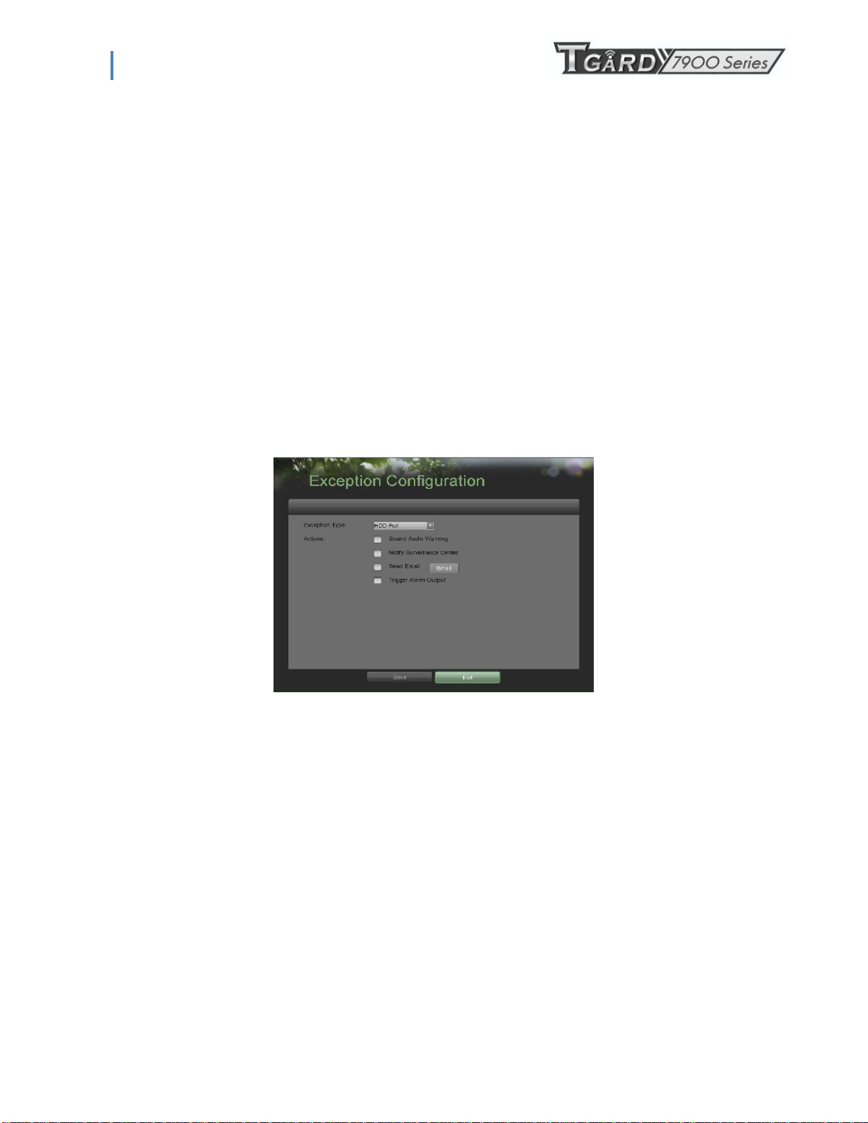
1. Enter the Exception Configuration menu, shown in Figure 48 by going to Main Menu > System Configuration >
Exception Configuration.
Figure 48. Exception Configuration Menu
2. Select the Exception Type to configure. The exception type includes:
• HDD Full: If selected, trigger action when HDD is full.
• HDD Error: If selected, trigger action when errors on the HDD are detected.
• Network Failure: If selected, trigger action when a network failure is detected.
• IP Conflict: If selected, trigger action if an IP conflict is detected.
• Illegal Login: If selected, trigger action when illegal logins are detected.
• Video Exception: If selected, trigger action when an exception such as distorted video is detected.
• Video Output Standard Mismatch: If selected, trigger action when video output standard does not match.
3. Select the Actions to take when the exception is detected. More than one action can be selected. The actions
available includes:
• Sound Audio Warning: DVR will sound an audio warning if exception is detected.
• Notify Surveillance Center: DVR will notify surveillance center if exception is detected.
• Send Email: DVR will send an email out to the designated recipients if exception is detected.
• Trigger Alarm Output: DVR will trigger alarm output if exception is detected. Selecting this option will
enable the Alarm Output list, where the output to trigger can be selected.
4. Select the Save button to save the exception settings and select Exit to return to the previous menu. Selecting the
Exit button without clicking Save will quit out of the menu without saving settings.
38
Page 39
PS-7900 Series User Manual
6.5.3 Configuring E-mail Settings
If you would like to have the DVR send out e-mails when certain events are detected or exceptions have been triggered,
you must first setup the e-mail settings.
To setup e-mail settings:
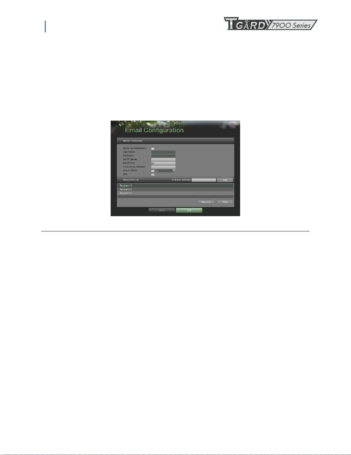
1. Enter the Email Configuration menu, shown in Figure 49 by going to Main Menu > System Configuration > Email
Configuration.
Figure 49. Email Configuration Menu
2. Under Server Information, enter all pertinent email information, including:
• Server Authentication: Enable if email server requires authentication. Enabling Server Authenticating will
enable the User Name and Password fields.
• User Name: User name to use for server authentication.
• Password: Password to use for server authentication.
• SMTP Server: Address for SMTP server.
• SMTP Port: Port for SMTP server.
• From Email Address: The From address to use when an e-mail is sent out from the DVR.
• Attach JPEG: Enabling will attach a small JPEG segment (duration can be set next to the Attach JPEG
checkbox) to the out-going e-mail.
• SSL: Enable Secure Sockets Layer (SSL) for out-going e-mail.
3. Enter To E-mail Address and click the Add button. The e-mail address will be added to the Recipients List.
4. You may now test the e-mail settings by clicking the Test button or remove an e-mail address off the Recipients
List by selecting the recipient and clicking
5. Remove.
6. Select the Save button to save the e-mail settings and select Exit to return to the previous menu. Selecting the
Exit button without clicking Save will quit out of the menu without saving settings.
39
Page 40
PS-7900 Series User Manual
C H A P T E R 7
Camera Management
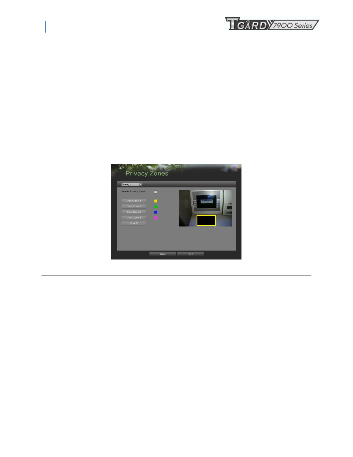
7.1 To setup privacy zones:
1. Enter the Privacy Zones menu, shown in Figure 50 by going to Main Menu > Camera Setup > Privacy Zones.
Figure 50. Privacy Zone Menu
2. Select the camera to setup privacy zones in using the camera drop down menu on the upper left of the menu. If
all cameras are to be configured with the same settings, select All Cameras from the list.
3. Click Enable Privacy Zones.
4. Up to four privacy zones can be used per camera and are shown using four different colors, yellow, green, blue
and pink. Using the mouse, click and drag out rectangular boxes defining the desired zones.
5. You may clear a privacy zone at any time by clicking on the corresponding Clear Zone button or Clear All button
to clear all zones.
6. Select the Save button to save the privacy zones settings and select Exit to return to the previous menu. Selecting
the Exit button without clicking Save will quit out of the menu without saving settings.
7.2 Configuring Video Tampering Detection
Video tampering detection can be used to recognize if an area of a camera is purposely covered and to respond accordingly.
To configure video tampering detection:
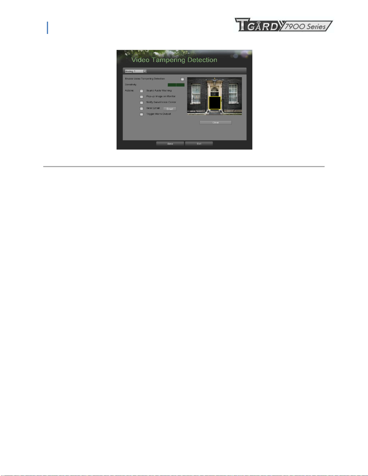
1. Enter the Video Tampering Detection menu, shown in Figure 51 by going to Main Menu > Camera Setup > Video
Tampering Detection
40
Page 41
PS-7900 Series User Manual
.
Figure 51. Video Tampering Detection Menu
2. Select the camera to setup video tampering detection in using the camera drop down menu on the upper left of the
menu. If all cameras are to be configured with the same settings, select All Cameras from the list.
3. Click Enable Video Tampering Detection.
4. Adjust the Sensitivity for video tampering detection.
5. Select Actions to take if video tampering is detected. More than one action can be selected per channel. These actions
include:
• Sound Audio Warning: DVR will sound an audio warning if tampering is detected.
• Pop-up Image on Monitor: DVR will show the corresponding channel that is associated with the tampered
channel.
• Notify Surveillance Center: DVR will notify surveillance center when tampering is detected.
• Send Email: DVR will send an email out to the designated recipients when tampering is detected.
• Trigger Alarm Output: DVR will trigger alarm output when tampering is detected. Selecting this option will
enable the Alarm Output list, where the output to trigger can be selected.
6. Select the Save button to save the privacy zones settings and select Exit to return to the previous menu. Selecting the
Exit button without clicking Save will quit out of the menu without saving settings.
Note: Video tampering area is defaulted as full screen. Area setting is not supported.
7.3 Configuring Video Loss Detection
Video loss detection can be enabled on any of the channels on your DVR to detect the loss of video.
To configure video loss detection:
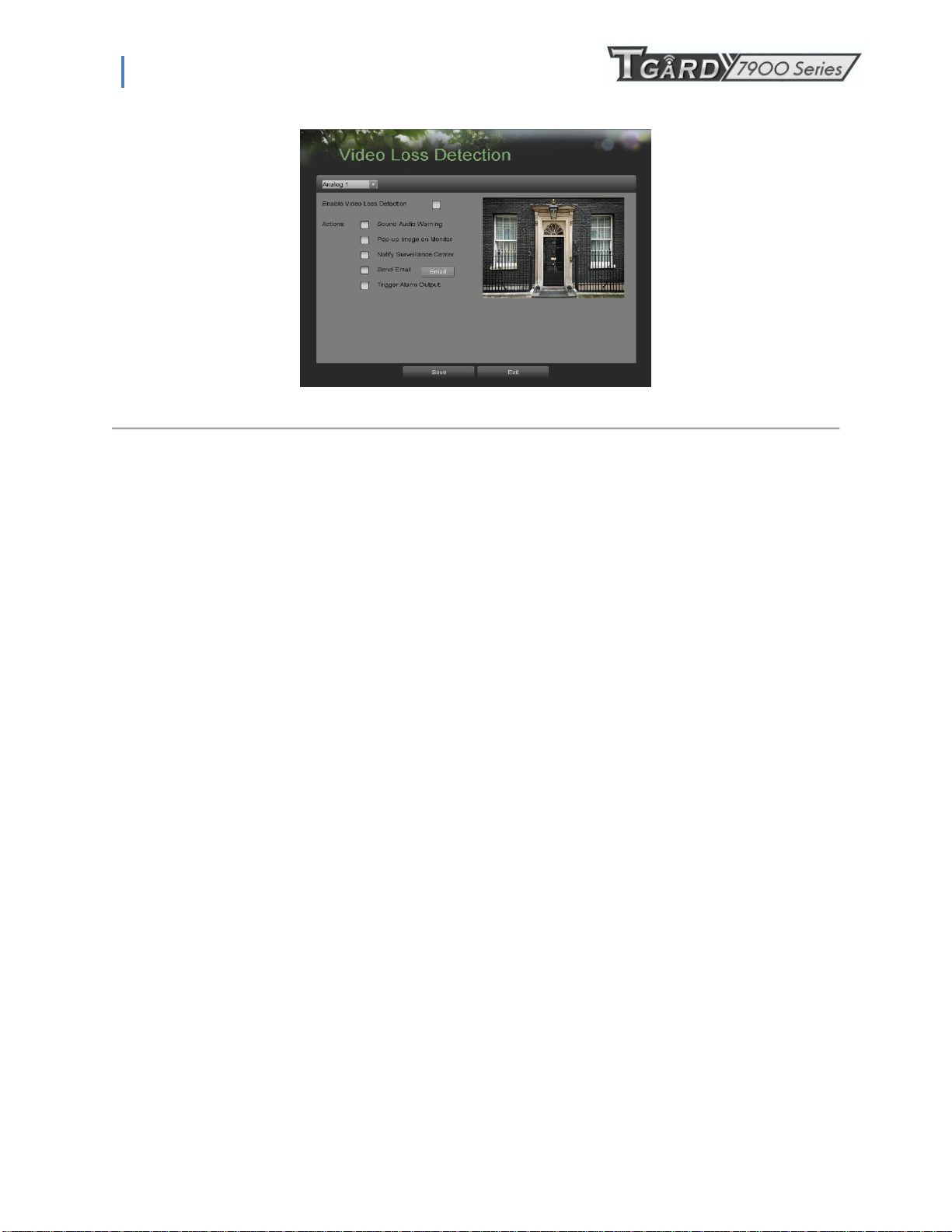
1. Enter the Video Loss Detection menu, shown in Figure 52 by going to Main Menu > Camera Setup > Video Loss
Detection.
41
Page 42
PS-7900 Series User Manual
Figure 52. Video Loss Detection Menu
2. Select the camera to setup video loss detection in using the camera drop down menu on the upper left of the menu. If all
cameras are to be configured with the same settings, select All Cameras from the list.
3. Click Enable Video Loss Detection.
4. Select Actions to take if video loss is detected. More than one action can be selected per channel. These actions
include:
• Sound Audio Warning: DVR will sound an audio warning if video loss is detected.
• Pop-up Image on Monitor: DVR will show the corresponding channel that is associated with the video loss
channel.
• Notify Surveillance Center: DVR will notify surveillance center when video loss is detected.
• Send Email: DVR will send an email out to the designated recipients when video loss is detected.
• Trigger Alarm Output: DVR will trigger alarm output when video loss is detected. Selecting this option will
enable the Alarm Output list, where the output to trigger can be selected.
5. Select the Save button to save the privacy zones settings and select Exit to return to the previous menu. Selecting the
Exit button without clicking Save will quit out of the menu without saving settings.
7.4 Configuring OSD Settings
On Screen Display (OSD) settings can be configured in the OSD Configuration menu. The OSD is shown in each display in Live
Feed and Playback mode.
To configure OSD settings:
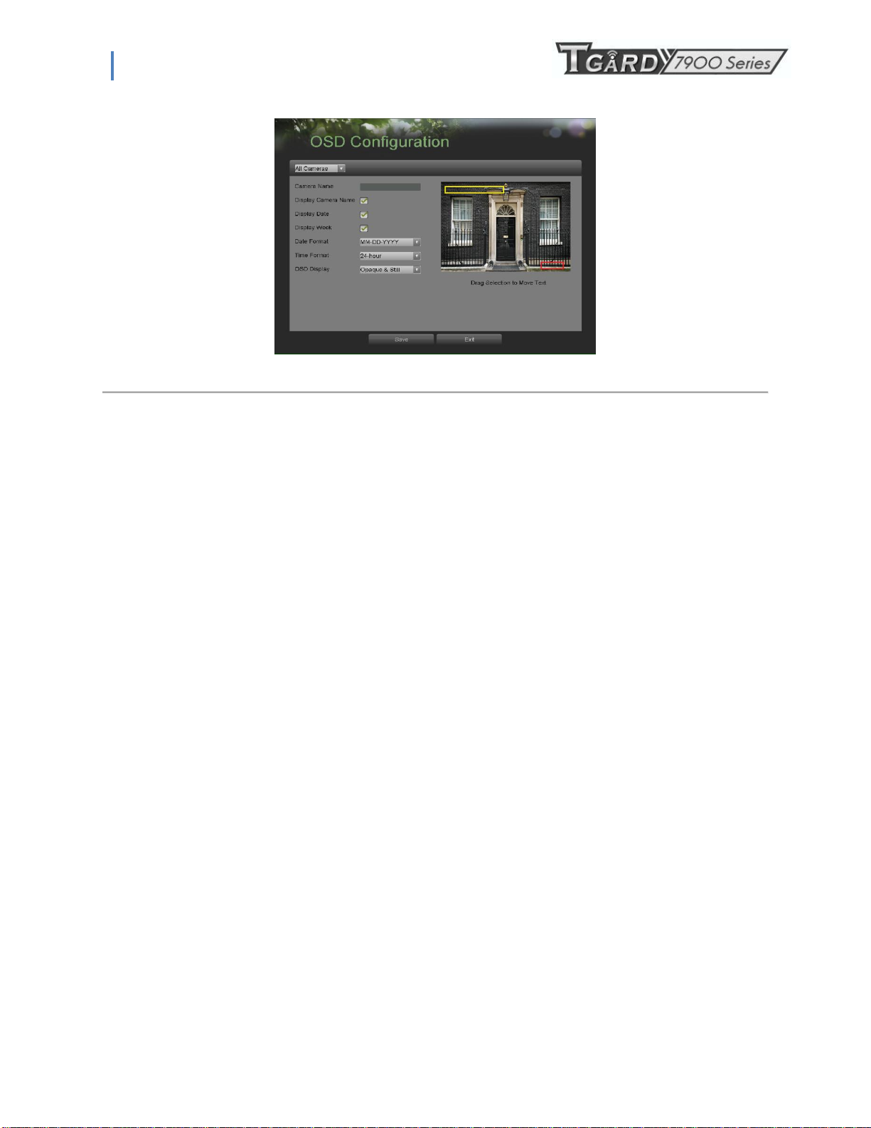
1. Enter the OSD Configuration menu, shown in Figure 53 by going to Main Menu > Cameras Setup > OSD
Configuration.
42
Page 43
PS-7900 Series User Manual
Figure 53. OSD Configuration Menu
2. Select the camera to setup OSD configuration in using the camera drop down menu on the upper left of the menu. If all
cameras are to be configured with the same settings, select All Cameras from the list.
3. Configure OSD settings, including:
• Camera Name: Name of selected camera.
• Display Camera Name: Enable to display camera name in OSD.
• Display Date: Enable to display date in OSD.
• Display Week: Enable to display week in OSD.
• Date Format: Format of date.
• Time Format: Format of time.
• OSD Display: Display style for OSD.
4. Using the mouse, click and drag OSD elements on preview screen to desired location.
5. Select the Save button to save the privacy zones settings and select Exit to return to the previous menu. Selecting the
Exit button without clicking Save will quit out of the menu without saving settings.
43
Page 44
PS-7900 Series User Manual
C H A P T E R 8
Disk Management
8.1 Managing Disks
8.1.1 Checking Disk Status
The status of all installed hard disk drives (HDD) can be checked under the Disk Management menu.
To check the status of installed disks:
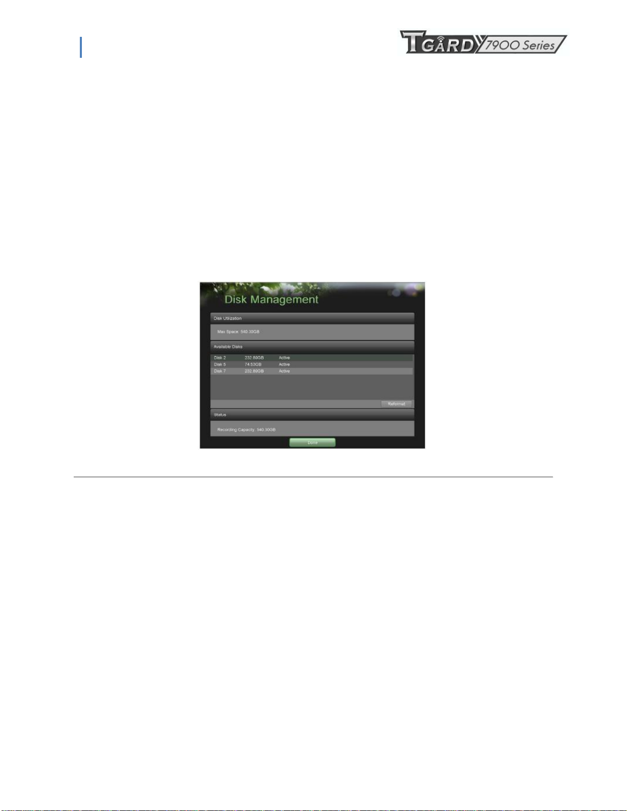
1. Enter the Disk Management menu, shown in Figure 54 by going to Main Menu > System Configuration > Disk
Management.
Figure 54. Disk Management Menu
2. There are four different panels found in the Disk Management menu. They include:
• Disk Utilization: Displays the maximum space available of all disks combined.
• Available Disks: Displays a list of all installed disks(include local and network) and their respective space
and status.
• Status: Displays the available disk space of all disks combined.
3. Click the Done button to exit out of Disk Management.
8.2 Formatting Disk
A newly installed hard disk drive (HDD) must be first formatted before it can be used with your DVR. Formatting the disk
will erase all data on it.
To format a new disk:
1. Enter the Disk Management menu, shown in Figure 54 by going to Main Menu > System Configuration > Disk
Management.
2. Select a disk to format. A disk that has not been formatted will show Error Detected as its status. If the disk is one
that is newly installed, the status of the drive will show up as Non-Active and the Reformat button will change to
the Add button.
3. Click the Reformat/Add button.
44
Page 45
PS-7900 Series User Manual
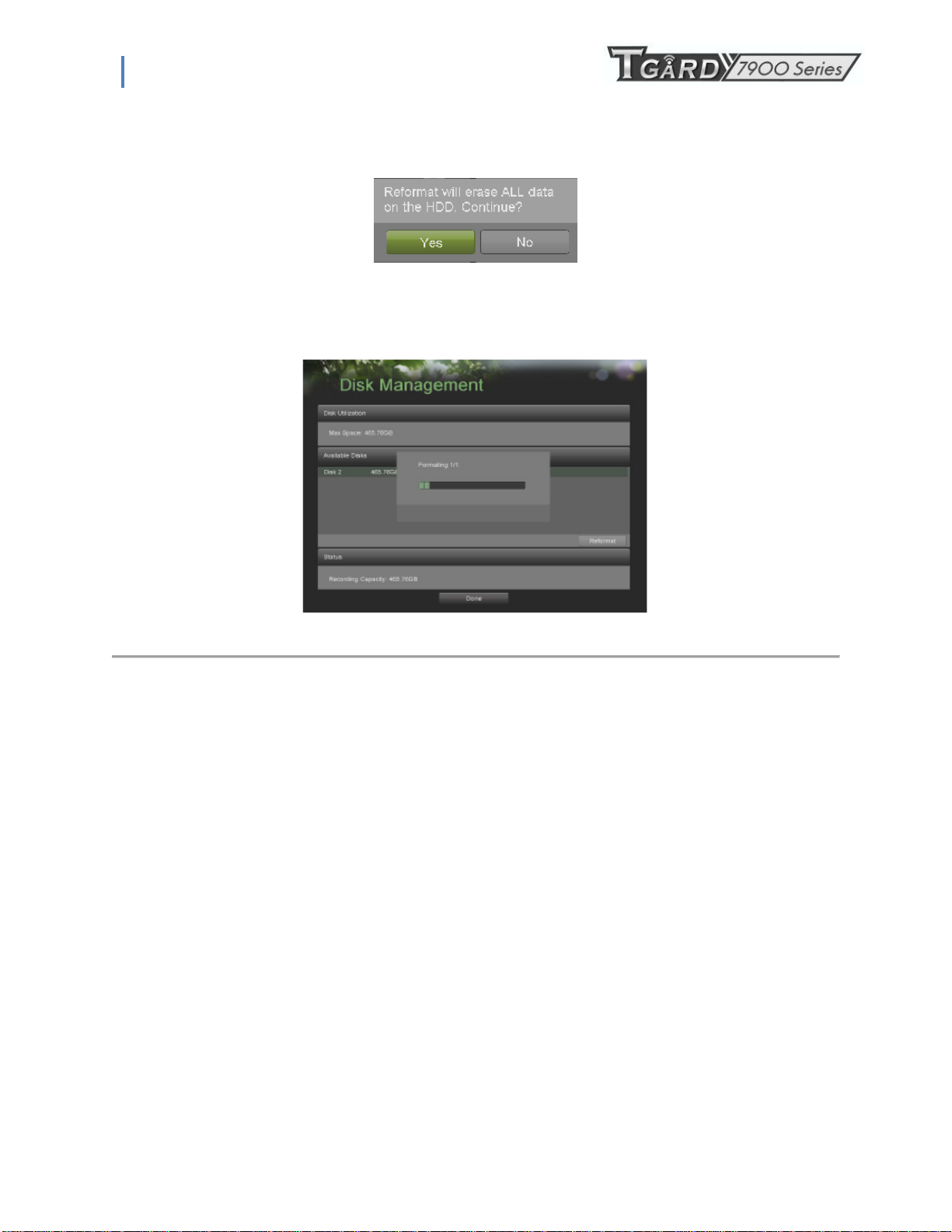
4. A confirmation message, similar to the one shown in Figure 55 will appear on the screen. Click the Yes button to
continue formatting process.
Figure 55. Disk Format Confirmation
5. A format progress bar (Figure 55) will be shown on the menu. After the disk has been formatted, the status of
the disk will change to Active.
Figure 55. Disk Format Progress Bar
6. Click the Done button to exit out of Disk Management.
8.2.1 Enabling Disk Overwrite
Enabling disk overwrite will allow the DVR to overwrite the installed disks once the disks are full.
To enable disk overwrite:
1. Enter the Disk Management menu, shown in Figure 54 by going to Main Menu > System Configuration > Disk
Management.
2. Check the Overwrite checkbox.
3. Click the Save button.
4. Click the Done button to exit out of Disk Management.
8.3 Managing Files
8.3.1 Searching for Recorded Files
Previously recorded files can be searched by criteria in the File Management menu.
To search for all recorded files:
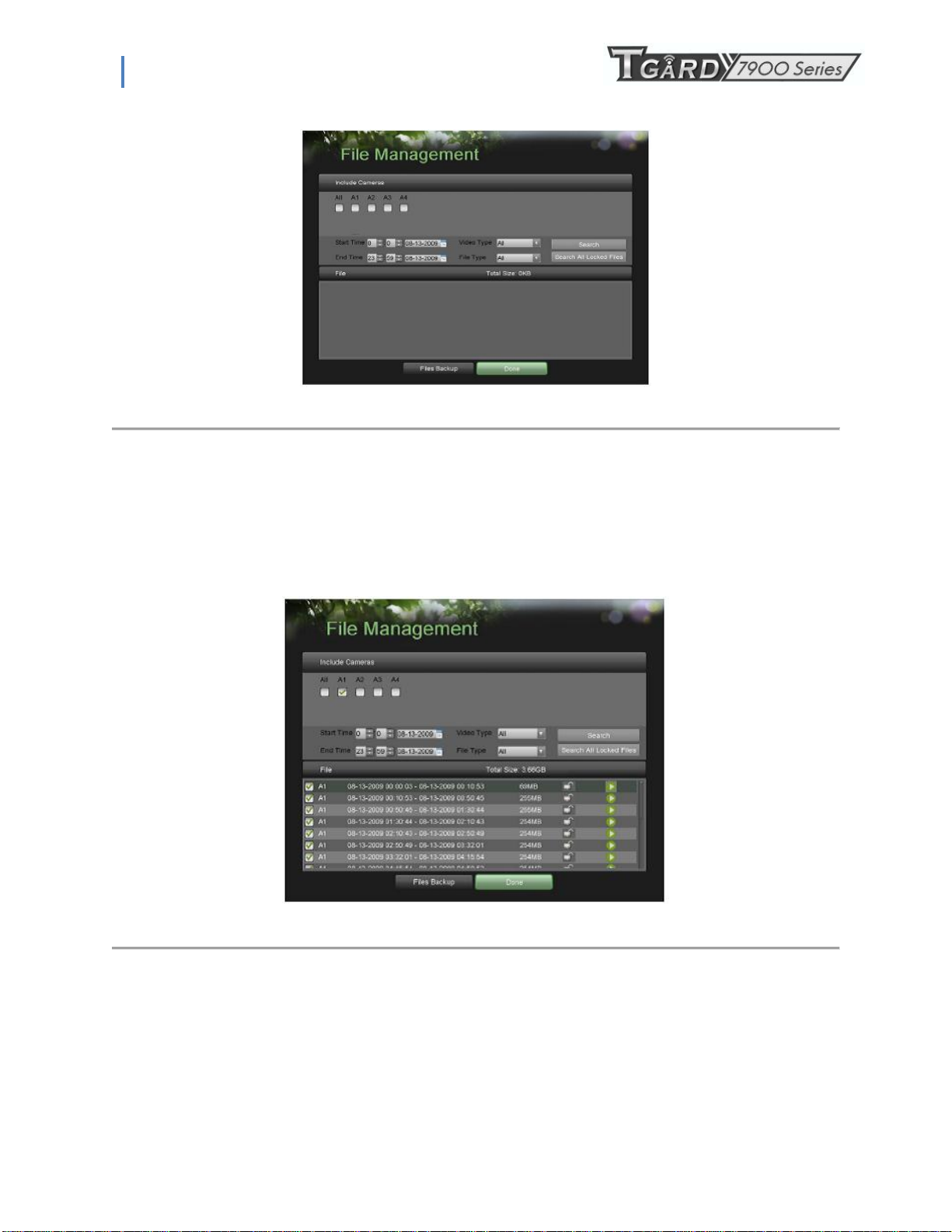
1. Enter the File Management menu, shown in Figure 56 by going to Main Menu > File Management.
45
Page 46
PS-7900 Series User Manual
Figure 56. File Search Menu
2. Select the cameras that you would like to include in the search. Analog cameras are listed on the first row, preceded
with the letter A. Digital cameras are listed on the second row, preceded with the letter D. If you would like include all
cameras in the search, check the All box.
3. Select the Start Time.
4. Select the End Time.
5. Select the Video Type. Video type includes Continuous and On Event recordings.
6. Select the File Type. File type includes Locked and Unlocked files.
7. Click the Search button or if you would like to search for only locked files, the Search All Locked Files button.
8. A list of results with your search criteria will be shown at the bottom of the menu (Figure 57).
9. You may now play the selected file by clicking the Play button that is next to the file.
10. Click the Done button to exit out of the File Management menu.
Figure 57. File Search Results
46
Page 47

PS-7900 Series User Manual
8.4 Locking and Unlocking Recorded Files
To lock and unlock recorded files:
1. Search for recorded files using the File Management menu (See Searching for Recorded Files on page 83).
2. Select the file you would like to lock/unlock.
3. Click the Lock icon for the selected file.
4. Click the Done button to exit out of the File Management menu.
Note: Locked files will never be overwritten until they are unlocked.
47
Page 48
PS-7900 Series User Manual
C H A P T E R 9
DVR Management
9.1 Managing System
9.1.1 Upgrading the System Firmware
The system firmware for your DVR can be updated from a USB storage device.
To update the system firmware:
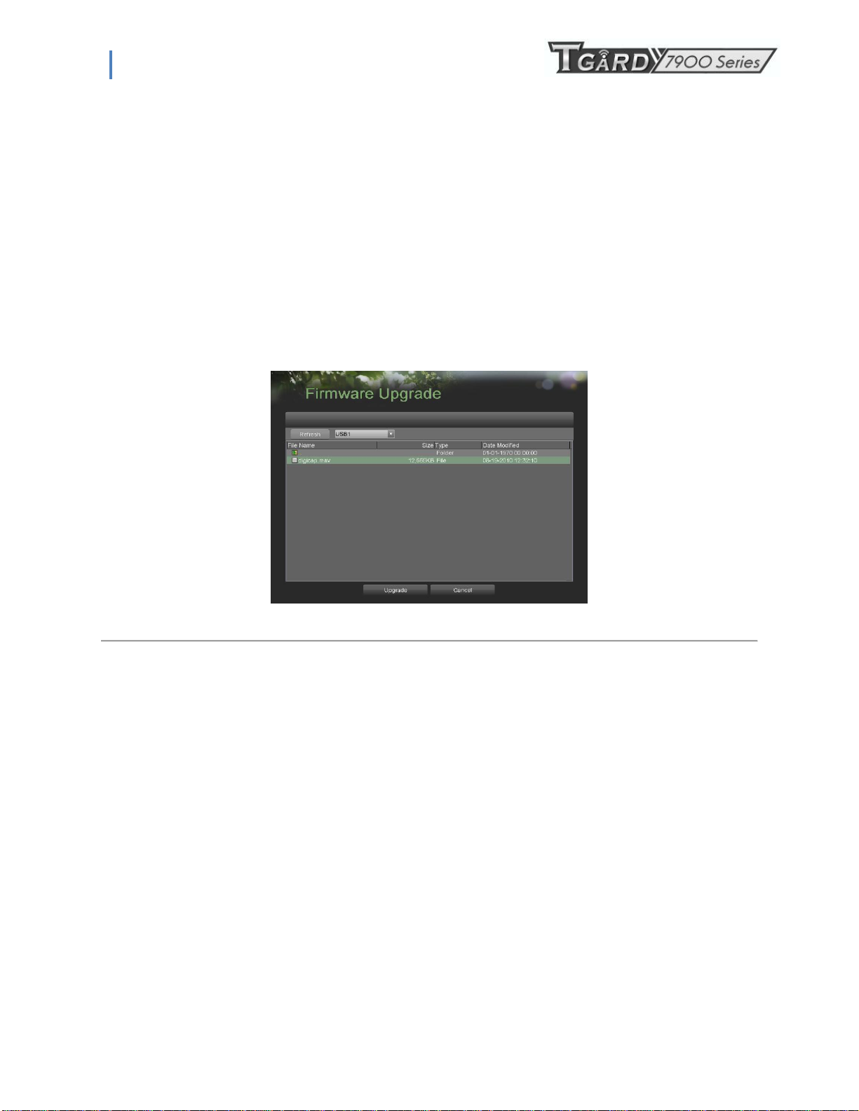
1. Enter the Firmware Upgrade menu, shown in Figure 58 by going to Main Menu > Maintenance > Firmware
Upgrade.
Figure 58. Firmware Upgrade Menu
2. Connect the USB storage device to a USB port on the DVR.
3. Click the Refresh button. The contents of the USB storage device will be shown on the screen.
4. Select the firmware file. The firmware file is named digicap.
5. Click the Upgrade button to upgrade the DVR. The DVR will automatically reboot after the upgrade is completed.
If you do not wish to upgrade at this point, click the Cancel button.
9.1.2 Restoring Default Settings
To restore factory default settings to your DVR:
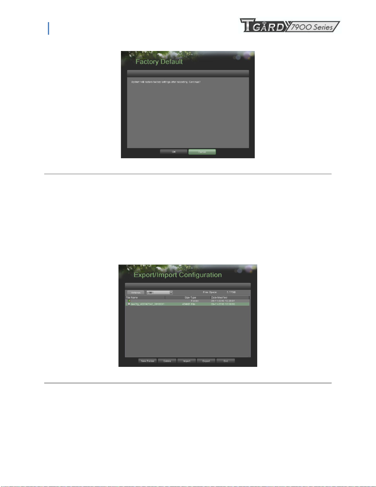
1. Enter the Factory Default menu, shown in Figure 59 by going to Main Menu > Maintenance > Factory Default.
48
Page 49
PS-7900 Series User Manual
Figure 59. Factory Default Menu
2. Select the OK button to restore factory defaults or select the Cancel button to return to the previous menu.
Note: Network information such as IP address, subnet mask and gateway will not be restored.
9.2 Exporting & Importing Configuration
Configuration information from your DVR can be exported to a USB storage device and imported into another DVR. This will
allow you to efficiently setup the same configuration on numerous DVRs.
To export DVR configuration:
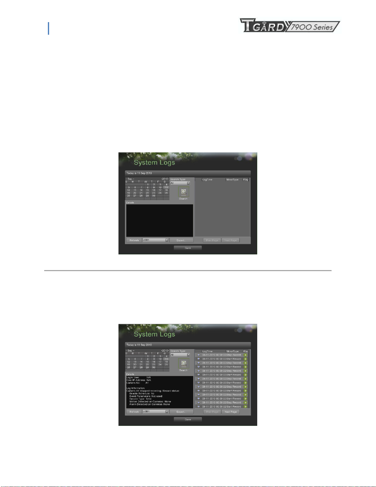
1. Enter the Export/Import Configuration menu, shown in Figure 60 by going to Main Menu > Maintenance >
Export/Import Configuration.
2. Connect the USB storage device to a USB port on the DVR.
3. Click the Refresh button. The contents of the USB storage device will be shown on the screen.
4. Click the New Folder button to create a new folder or the Delete button to delete a file/folder.
5. Select the location where you would like the configuration to be stored on the USB storage device.
6. Click Export to export a configuration file to USB storage device. The configuration file will be named devCfg.bin.
7. Click the Exit button to exit out of the Export/Import Configuration menu.
To import DVR configuration:
Figure 60. Import/Export Configuration Menu
49
Page 50
PS-7900 Series User Manual
1. Enter the Export/Import Configuration menu, shown in Figure 65 by going to Main Menu > Maintenance >
Export/Import Configuration.
2. Connect the USB storage device to a USB port on the DVR.
3. Click the Refresh button. The contents of the USB storage device will be shown on the screen.
4. Select the configuration file. The configuration file is named devCfg.bin.
5. Click the Import button.
6. Click the Exit button to exit out of the Export/Import Configuration menu.
9.3 Viewing System Logs
Many events of your DVR are logged into the system logs. To access the system logs and search for these events:
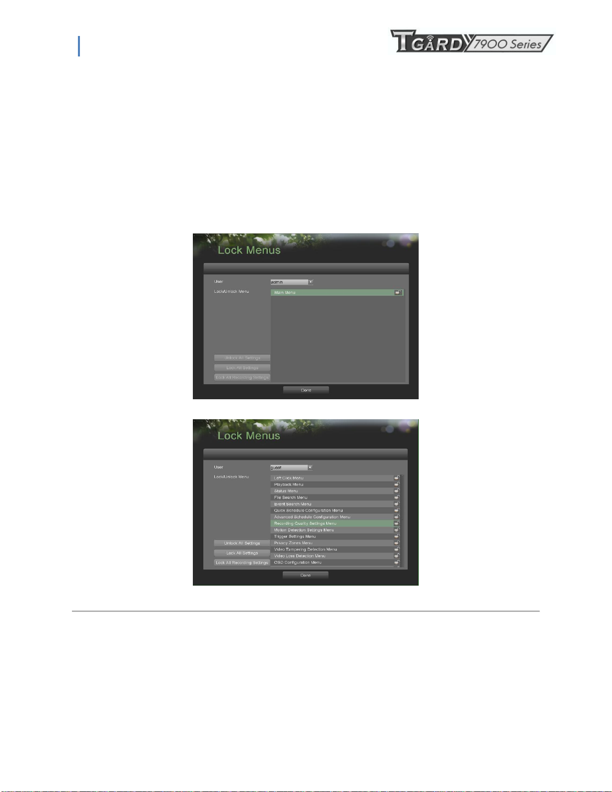
1. Enter the System Logs menu, shown in Figure 61 by going to Main Menu > Maintenance > System Logs.
Figure 61. System Logs Menu
2. Select the date from the Calendar to search for system logs in. The current system date is displayed in the upper left
corner of the menu.
3. Select the log type using the Search Type drop down list. Four log types are available: Alarm, Exception, Operation,
Information.
4. Click the Search button. The search results will be displayed in a list on the right side of the menu (Figure 62). If there
are more than 2000 entries, click the Prev Page or Next Page button to display more entries.
Figure 62. System Log Search Results
50
Page 51
PS-7900 Series User Manual
5. Select an entry to view more detail information about the entry.
6. If applicable, you may also view the associated video to the selected log entry by clicking the Play button.
7. Log files can also be exported onto a USB storage device. To export a log file, connect a USB storage device to the
DVR, select the log files to export and click the Export button.
8. Click the Done button to exit out of menu.
9.4 Locking and Unlocking System Menus
System menus on your DVR can be locked to prevent unauthorized local access.
To lock and unlock system menus:
1. Enter the Lock Menus menu, shown in Figure 63 by going to Main Menu > Maintenance > Lock Menus.
Figure 63. Lock Menus Menu
Figure 64. Lock Menus Menu
2. If you select Administrator(see Figure 68),there is only Main menu you can choose to lock/unlock.
3. If you select other users(see Figure 69),select the menus you would like to lock/unlock by selecting the Lock icon
beside the menu‟s name in the list on the right. You may also choose to lock and unlock all settings or just recording
settings by clicking on the corresponding buttons (Unlock All Settings, Lock All Settings, Lock All Recording
Settings).
4. Once a system menu is locked, access to that menu will only be granted after the correct Admin password is entered.
5. Click the Done button to save settings and to return to the previous menu.
51
Page 52

PS-7900 Series User Manual
Note: In the Lock/Unlock Menu list, you can‟t modify menus if they appear dark grey.
Note: Lock Menus menu is available when current user is Administrator.
52
 Loading...