

TFT 5290 User Manual

P/N 5004-5200 REV. A (Preliminary)
APRIL 2005
EQUIPMENT SERIAL NO.
SHIPMENT DATE
ANALOG STUDIO TO TRANSMITTER LINK
Model 5290 STL Transmitter
Model 5291 STL Receiver
USER’S GUIDE
Preliminary
1953 Concourse Drive
San Jose, California 95131-1708 USA
TEL: (+1) 408 943-9323
FAX: (+1) 408 943-9218
EMAIL: techsupport@TFTInc.com
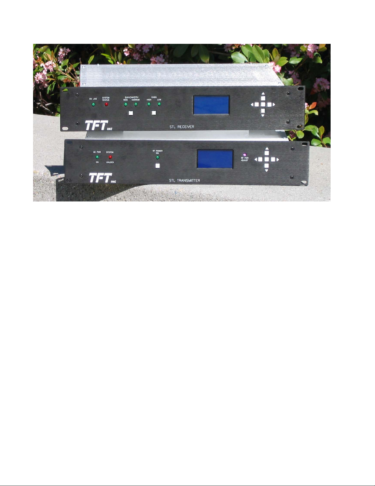
MODEL 5291
STL RECEIVER
MODEL 5290
STL TRANSMITTER
The TFT 5200 Analog STL Series consists of a transmitter and receiver pair that accommodates a
single RF channel. The transmitter is either composite or mono. Receivers are available in
composite/mono, composite only, and monaural only versions. Both the transmitter and receiver are
frequency agile across a specific band and all bands from 140 MHz to 1.7 GHz are available. The
Model 5290 Transmitter covers 944-952 MHz, along with its companion composite/mono receiver,
the Model 5291.
The transmitter has a 20-Watt output and is frequency agile in 6.25 kHz steps, set by front panel
switches.
FEATURES:
• 20 Watts
• Selectable Pre-/De-Emphasis
• Frequency Agile
• Composite or mono, jumper selectable
• Wideband or narrowband
• Frequency Stability 0.0005%
• THD <0.05%
• SNR >80 dB
ii
• 10 µV sensitivity for 60 dB SNR
• 152 kHz MUX available
• Front Panel LCD
• Modulation Bargraph
• Type N RF Connectors
• FCC ID: BIO5290*(Pending)

TABLE OF CONTENTS
Paragraph Title Page
Section I – GENERAL INFORMATION
1.1 INTRODUCTION………………………………………………………………………………... 1-1
1.2 EQUIPMENT DESCRIPTION………………………………………………………………….. 1-1
1.3 SPECIFICATIONS………………………………………………………………………………. 1-2
1.4 FCC DESIGNATOR………………………………………………………….………………….. 1-3
1.5 WARRANTY INFORMATION………………………………………………………………… 1-3
1.6 CLAIMS FOR DAMAGE IN SHIPMENT………………………………….…………………. 1-3
1.7 TECHNICAL SUPPORT………………………………………………………………………... 1-3
Section II – GETTING TO KNOW YOUR SERIES 5200 STL AND RELATED
EQUIPMENT
2.1 INTRODUCTION………………………………………………………………………………
…
2.2 UNPACKING &
INSPECTION………………………………………………………………….
2.3 THE 5290 STL TRANSMITTER FRONT
PANEL……………………………………………..
2.4 THE 5290 STL TRANSMITTER REAR
PANEL……………………………………….……...
2.5 THE 5291 STL RECEIVER FRONT
PANEL………….……………………………………….
2.6 THE 5291 STL RECEIVER REAR
PANEL…………….………………….…………………...
2.7 RELATED
EQUIPMENT………………………………………………………………………...
2.8 PRE-INSTALLATION
INFORMATION……………………………………………………….
2-1
2-1
2-1
2-2
2-3
2-4
2-4
2-5
Section III – PRE-INSTALLATION CHECKOUT
3.1 INTRODUCTION………………………………………………………………………………
…
3.2 PRIMARY POWER 3-1
ii
3-1

Paragraph Title Page
APPLICATION……………………………………………………………
iii

Section IV - OPERATING
4.1 INTRODUCTION………………………………………………………………………………... 4-1
4.2 OVERVIEW OF OPERATION………………………………………………………………… 4-1
4.3 SETTING TRANSMITTER
4-1
PARAMETERS…………………………………………………...
4.4 OBSERVING TRANSMITTER
4-1
OPERATING...……………………………………………….
4.5 SETTING RECEIVER
4-1
PARAMETERS…..…………………………………………………….
Section V – INSTALLATION
5.1 INTRODUCTION………………………………………………………………………………
5-1
…
Section VI – THEORY OF OPERATION
6.1 GENERAL …………………………………………………………………………………….…. 6-1
6.2 MODEL 5290 STL TRANSMITTER BASIC DIAGRAM DESCRIPTION...……………….. 6-1
6.3 MODEL 5291 STL RECEIVER BASIC DIAGRAM
6-1
DESCRIPTION..………………………
Section VII – MAINTENANCE AND REPAIR
7.1 INTRODUCTION………………………………………………………………………………
7-1
…
7.2 TOOL AND TEST EQUIPMENT
7-1
REQUIREMENTS…………………….…………………...
7.3 ROUTINE
7-1
MAINTENANCE……………………………………………………………………..
7.3.1
7-1
Calibration……………………………………………………………………………………...
7.4 DIAGNOSTICS AND
7-1
REPAIR…………………………………………………………………..
7.5 TFT CUSTOMER SERVICE
7-1
DEPARTMENT…………………………………………………
iv

Section VIII – ENGINEERING DRAWINGS
v

List of Figures
Figure Title Page
2.3-1 Model 5290 STL Transmitter Front Panel 2-1
2.4-1 Model 5290 STL Transmitter Rear Panel 2-2
2.5-1 Model 5291 STL Receiver Front Panel 2-3
2.6-1 Model 5291 STL Receiver Rear Panel Connectors 2-4
List of Tables
Table Title Page
1.3-1 Transmitter and Receiver Specifications 1-2
2.3-1 Model 5290 STL Transmitter Front Panel Controls and Indicators 2-1
2.4-1 Model 5290 STL Transmitter Rear Panel Connectors 2-2
2.5-1 Model 5291 STL Receiver Front Panel Indicators and Controls 2-3
2.6-1 Model 5291 STL Receiver Rear Panel Connectors 2-4
vi

SECTION I
GENERAL INFORMATION
1.1 INTRODUCTION
This Model 5200 STL User’s Guide is arranged in seven sections, as follows:
Section I: General Information
A general description of the 5200 Series Transmitter, its specifications, general information on the FCC designator, warranty
and damage claim procedures, and technical support information.
Section II Getting To Know Your Model 5200 Series Transmitter and Receiver and Related Equipment
Overview of the various system components of the 5200 Series Transmitter and Receiver and related equipment. Control and
Indicator functions, basic component functions, and their interconnection.
Section III: Pre-Installation Checkout
Some basic test methodology on the Transmitter and Receiver and their related equipment. The user should find it useful to
perform the tests in this section with all the 5200 Series Transmitter and Receiver equipment on a lab bench.
Section IV: Operating the Transmitter and Receiver
Detailed description of setup procedures of various Transmitter and Receiver system parameters, as well as enabling of
optional features.
Section V: Installation
Instruction for installing and adjusting various system components of the 5200 Series Transmitter and Receiver.
Section VI: Theory of Operation
Basic description of transmitter and receiver circuits
Section VII: Maintenance and Repair
Describes routine maintenance procedures and tools and equipment requirements.
Section VIII: Engineering Drawings
1.2 EQUIPMENT DESCRIPTION
The TFT 5200 Analog STL Series consists of a transmitter and receiver pair that accommodates a
single RF channel. The transmitter is either composite or mono. Receivers are available in
composite/mono, composite only, and monaural only versions. Both the transmitter and receiver are
frequency agile across a specific band and all bands from 140 MHz to 1.7 GHz are available. The
Model 5290 Transmitter covers 944-952 MHz, along with its companion composite/mono receiver,
the Model 5291.
The transmitter has a 20-Watt output and is frequency agile in 6.25 kHz steps, set by front panel
switches.
1-1

1.3 SPECIFICATIONS
The Transmitter and Receiver System Specifications are listed in Table 1.3-1.
Table 1.3-1. DIGITAL TRANSMITTER AND RECEIVER SYSTEM SPECIFICATIONS
SYSTEM
Frequency……………………940-960 MHz (other
frequencies available)
Step Size………………… ....6.25 kHz
Frequency Stability…….......± 5 ppm (±0.0005)%
Occupied Bandwidth…… ....
≤ 300 kHz or 500
kHz, depending upon
MUX
I/O Connector…………… ....XLR, 600
Ω
Frequency Response…… ...± 0.1 dB
(20 Hz to 15 kHz)
Distortion………………… ....< 0.03% at 1 kHz
Stereo Separation………….. ................................................ . dB ............................................. .......................> 55
Signal-to-Noise……………..> 80 dB
RF Dynamic Range……. .....>40 dB
Mono Input……………………0 dBm, balanced,
bridging
MUX Input……………………1.23 V
p-p
2k
RECEIVER
RF Input Connector...………Type N, female, 50
Sensitivity/Threshold……… -86.9 dBm
for 60 dB SNR
Composite Outputs…………3 V
low impedance
p-p
to drive2k termination, unbalanced,
BNC
Mono Output Level……..…. 0 to + 4 dBm, XLR
male, 600
Nonlinear Crosstalk……......< 50 dB
MUX Channel…………… ....152 kHz on 500 kHz
version
TRANSMITTER
Output Power…………….....20 Watts (maximum)
Output Impedance……… ....50
Output Connector……….. ...Type N (female)
Composite Input………… ....3 V
p-p
2k Ω,
unbalanced, BNC
MECHANICAL AND ENVIRONMENTAL (Transmitter
and Receiver)
Dimensions…………………19 x 3.5 x 17 (inches)
48.3 x 8.9 x 43.2 (cm)
Weight……………………….20 lbs. (9 kg)
AC Power Requirements….120/240 VAC 50/60
Hz
Transmitter………..150 Watts
Receiver..………….20 Watts
Operating Temperature....... 0° to +50° C.
1.4 FCC DESIGNATOR and ID
Type Certification under FCC Part 74 has been submitted. The FCC emission designators are:
80KF3E (mono) for 300 kHz channels
284KF9E (composite) for 300 kHz channels
404KF9E (composite with 152 kHz MUX) for 500 kHz channels
The FCC ID is BIO5290.
1-2
 Loading...