

Page 1

1
NTP80plus Multiport Time
Server Reference Manual
GPS Version
Revision H
March 2018
MANUAL P/N 900000165 REV H
Page 2

2
Read First: Safety Information
Warnings and Cautions
Warnings ...
(1) Dangerous voltages exist in this equipment. Do not
attempt any repair without first switching off power to the
system, at the front panel switch, and removing the power
input connector.
(2) Nickel, cadmium and lithium are toxic substances. The
nickel cadmium battery or lithium battery is dangerous if
broken or dismantled. If any battery chemicals come into
contact with skin, wash with copious amount of water, and
seek medical attention as required. If the battery is
swallowed seek immediate medical attention. Return any
faulty batteries to the manufacturer, properly packaged,
for disposal.
(3) Most board assemblies contain tantalum capacitors or
electrolytic capacitors. Both types can explode under fault
conditions. Take appropriate precautions when servicing
the unit with the lid removed.
Caution ...
a) This unit should only be serviced by qualified personnel, no
user serviceable parts inside.
b) Several Board Assemblies contain static sensitive devices.
Appropriate procedures must be used when handling
these items.
MANUAL P/N 900000165 REV H
Page 3

3
Head Office
Time & Frequency Solutions Ltd
25 Eastways
Witham
Essex
CM8 3AL
United Kingdom
Phone: +44 (0) 1376 514114
Fax: +44 (0) 1376 516116
www.timefreq.com
Copyright and Trademarks
© 2018, Time & Frequency Solutions Ltd and Brandywine Communications Inc. All rights
reserved. No part of this manual may be copied, reproduced, translated, or reduced to any
electronic medium or machine-readable form for any use other than with the
Time & Frequency Solutions NTP80plus Network Time Server.
All trademarks are the property of their respective owners.
MANUAL P/N 900000165 REV H
Page 4

4
Revisions
Date
Revision History
A
July 12 2011
Initial Release
B
October 13 2011
Specification Update, Product Pictures, Login
C
November 28 2011
Correct LED indicator table. Add Appendix A
for firmware upload and Factory Defaults.
D
December 22 2012
Update to include all improvements to
NTP80plus. NTP80plus additional.
E
August 11 2016
Update to include new UI screenshots
F
May 4 2017
Reformatted to meet Brandywine Document
Style.
G
November 2017
Updated to reflect latest firmware changes
H
March 2018
Updated temperature specifications
Revision History
MANUAL P/N 900000165 REV H
Page 5

5
Table of Contents
1 Introduction ......................................................................................................7
1.1 Introduction to the NTP80plus Multiport Time Server ...................................7
1.2 Packaging .....................................................................................................8
1.3 Getting to know your NTP80plus ..................................................................9
1.3.1 NTP80plus Time Server .............................................................................9
1.3.2 GPS Antenna .............................................................................................9
2 Site Preparation ............................................................................................. 11
2.1 Overview ..................................................................................................... 11
2.2 Antenna ...................................................................................................... 11
2.3 Power and Network .................................................................................... 11
3 Quick Setup Guide ......................................................................................... 12
3.1 Installation .................................................................................................. 12
3.2 Initial Configuration ..................................................................................... 12
3.3 Main Configuration ...................................................................................... 12
3.3.1 Security .................................................................................................... 12
3.3.2 Network Configuration .............................................................................. 13
3.3.3 NTP Configuration .................................................................................... 14
4 NTP80plus Connections ................................................................................ 15
4.1 GPS Antenna Connections (GPS Version) ................................................. 15
4.2 GPS Head-End ........................................................................................... 15
4.3 1 PPS ......................................................................................................... 15
4.4 User port ..................................................................................................... 16
4.5 100 BASE T Ports ....................................................................................... 17
4.6 Power Connection ...................................................................................... 17
5 Web-based configuration ............................................................................... 18
5.1 System Security ................................................................ .......................... 19
5.2 Network Configuration ................................................................................ 20
5.3 Configure, NTP Configuration ..................................................................... 23
5.4 Status ......................................................................................................... 25
5.5 Events ......................................................................................................... 27
5.6 Remote restart ............................................................................................ 29
6 Front Panel Setup & Status. .......................................................................... 31
7 Working with the TFS Network Management System .................................... 35
8 Understanding the Network Time Protocol. ................................................... 37
8.1 Why use the Network Time Protocol ........................................................... 37
8.2 Understanding NTP .................................................................................... 38
8.3 NTP Hierarchical Structure ......................................................................... 39
9 Frequently Asked Questions .......................................................................... 40
10 Troubleshooting Guide .................................................................................. 42
11 Specifications ................................................................................................ 44
12 Appendix A .................................................................................................... 46
12.1 Resetting Factory Defaults. ........................................................................ 46
12.2 Firmware update ......................................................................................... 47
13 Appendix B: MIB File ..................................................................................... 49
13.1 TFS-NTPCOMMON-MIB.mib ...................................................................... 49
MANUAL P/N 900000165 REV H
Page 6

6
13.2 TFS-GPS-MIB.mib ...................................................................................... 53
13.3 TFS-NTP-MIB.mib ...................................................................................... 55
14 Support Information ....................................................................................... 57
MANUAL P/N 900000165 REV H
Page 7

7
1 Introduction
1.1 Introduction to the NTP80plus Multiport Time Server
Congratulations on the purchase of your Time & Frequency Solutions NTP-Multiport Time
Server, Model Number NTP80plus.
This manual shows you how to install, configure and operate your NTP80plus to provide an NTP
time server for your network. Once up and running the NTP80plus will provide accurate time
synchronisation for your computer clients to within milliseconds on a LAN and tens of
milliseconds over a WAN,
Prior to installing the NTP80plus please read the site preparation section first to ensure the
smooth operation of your NTP80plus when it is installed. Then follow the quick setup guide to
get your NTP80plus up and running. The remaining sections give more details on the
configuration and operation of the NTP80plus.
Feedback
At Time & Frequency Solutions we pride ourselves on a quality product and our superior
service. If you wish to comment on this, or provide improved feedback on this manual then
please feel free to contact us. You may email us at [email protected] or contact as at the
following -
Time & Frequency Solutions Ltd
25 Eastways
Witham
Essex
CM8 3AL
United Kingdom
Tel +44 (0) 1376 514114
Fax +44 (0) 1376 516116
MANUAL P/N 900000165 REV H
Page 8

8
1.2 Packaging
The NTP80plus Time Server is supplied as a package, and will contain the following items.
Before you start please check that you have been supplied all of the components.
Component Notes
NTP80plus Network Time Server.
GPS Antenna GPS Version Only
30m RG58 cable GPS Version Only
Factory Configuration Sheet
If your packaging is short of any item please contact us immediately. Your component list may
differ from the above if specific accessories or optional extras were order.
MANUAL P/N 900000165 REV H
Page 9
9
1.3 Getting to know your NTP80plus
1.3.1 NTP80plus Time Server
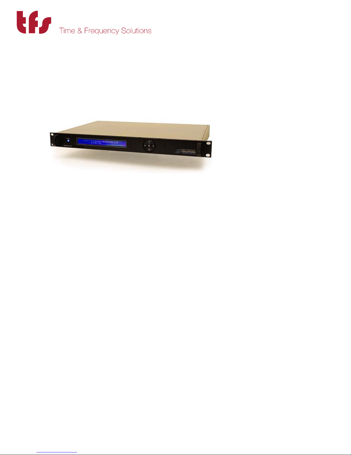
This is the base product / unit and is the main integral part of the NTP80plus system.
1.3.2 GPS Antenna
The NTP80plus requires an antenna for it to synchronise with GNSS satellites. The NTP80plus is
supplied with a GPS antenna, and 30 metres of RG58 cable.
What other equipment is required.
The NTP80plus will require an RJ45 Patch Cable for connection to function correctly as a
Network Time Server.
Initial or re-configuration will require a PC and Web Browser.
MANUAL P/N 900000165 REV H
Page 10

10
MANUAL P/N 900000165 REV H
Page 11

11
2 Site Preparation
2.1 Overview
The NTP80 GPS version is supplied with
The NTP80 unit
GPS/GNSS Antenna
30m RG58 cable
Serial breakout cable (15pin D only)
2.2 Antenna
To prepare the site for the NTP80 installation a suitable antenna location has to be found.
The antenna is a sealed unit. It should be located outside where there is good sky-coverage (e.g.
on a roof) and away from high frequency electrical interference sources. It is highly
recommended to use the fixings supplied and not to make any additional holes for fixing since
this compromises the IP65 rating of the antenna.
The antenna is supplied with 30m of RG58 cable. If longer cable runs are required, it is possible
to use a higher quality cable such as RG213 or RG218.
Type of Cable Maximum Length of Cable
RG58 34m
RG213 72m
RG217 95m
RG218 141m
2.3 Power and Network
The NTP80 requires 90-240V AC @ 50-60Hz for power and has three RJ45 network connections.
MANUAL P/N 900000165 REV H
Page 12

12
3 Quick Setup Guide
3.1 Installation
Ensure the power, network and antenna connections have been provided as described in
section 2.
Connect the antenna to the BNC connector labelled antenna on the rear of the unit along with
power and a network connection. The network ports are supplied with default IP addresses of:
ETH1 192.168.101.10
ETH2 192.168.102.10
ETH3 192.168.103.10
3.2 Initial Configuration
The NTP80 is configured using a web browser. There are two options in order to access the web
configuration
a/ use the front panel to set an IP address to your local subnet. See section 6 on how to do this.
b/ use the default IP address of 192.168.101.10 on ETH1 with a PC or laptop that is configured
for this network subnet.
Then in either case the web configuration below can followed.
3.3 Main Configuration
The default username and password to access the web interface is
admin
ThePassword
3.3.1 Security
If you wish to change these settings then use the SYSTEM button on the right. Refer to section
5.1 on how to change the settings.
MANUAL P/N 900000165 REV H
Page 13
13
3.3.2 Network Configuration
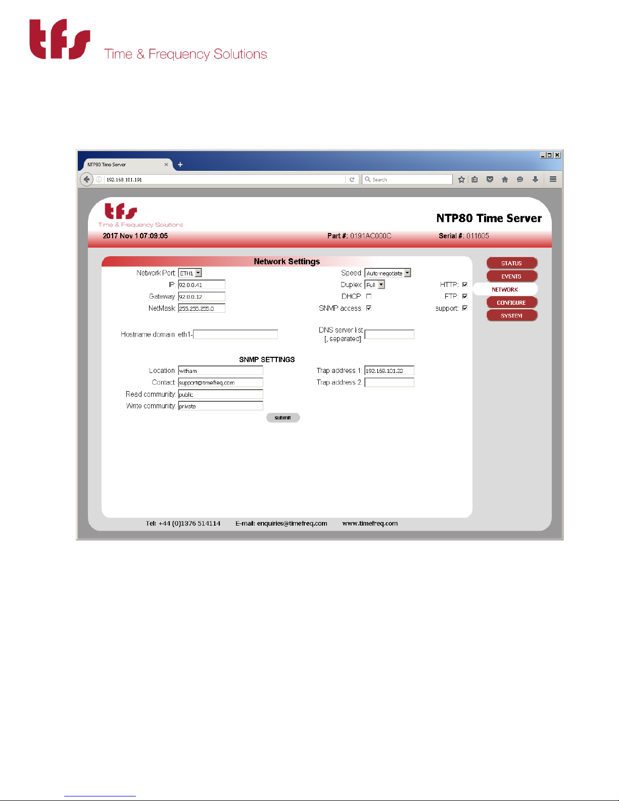
Use the network button on the right to select the network configuration page. This provides
configuration for all the network settings, IP addresses, SNMP and service selection for the
network ports.
Configure each port as required. Note that submit must be pressed for each port modified.
Changing ports without submitting will lose any changes.
Select the services required for the port, SUPPORT provides telnet access and is used for factory
support only. FTP is only used for new firmware updates.
Once the settings have been made press submit.
Depending on whether the IP address of the port being accessed is being changed the page will
show either some reconfiguration information or a link to the new address. Click this link to
MANUAL P/N 900000165 REV H
Page 14
14
return to the status page otherwise use the STATUS button. These steps are shown in more detail
in section 5.2
3.3.3 NTP Configuration
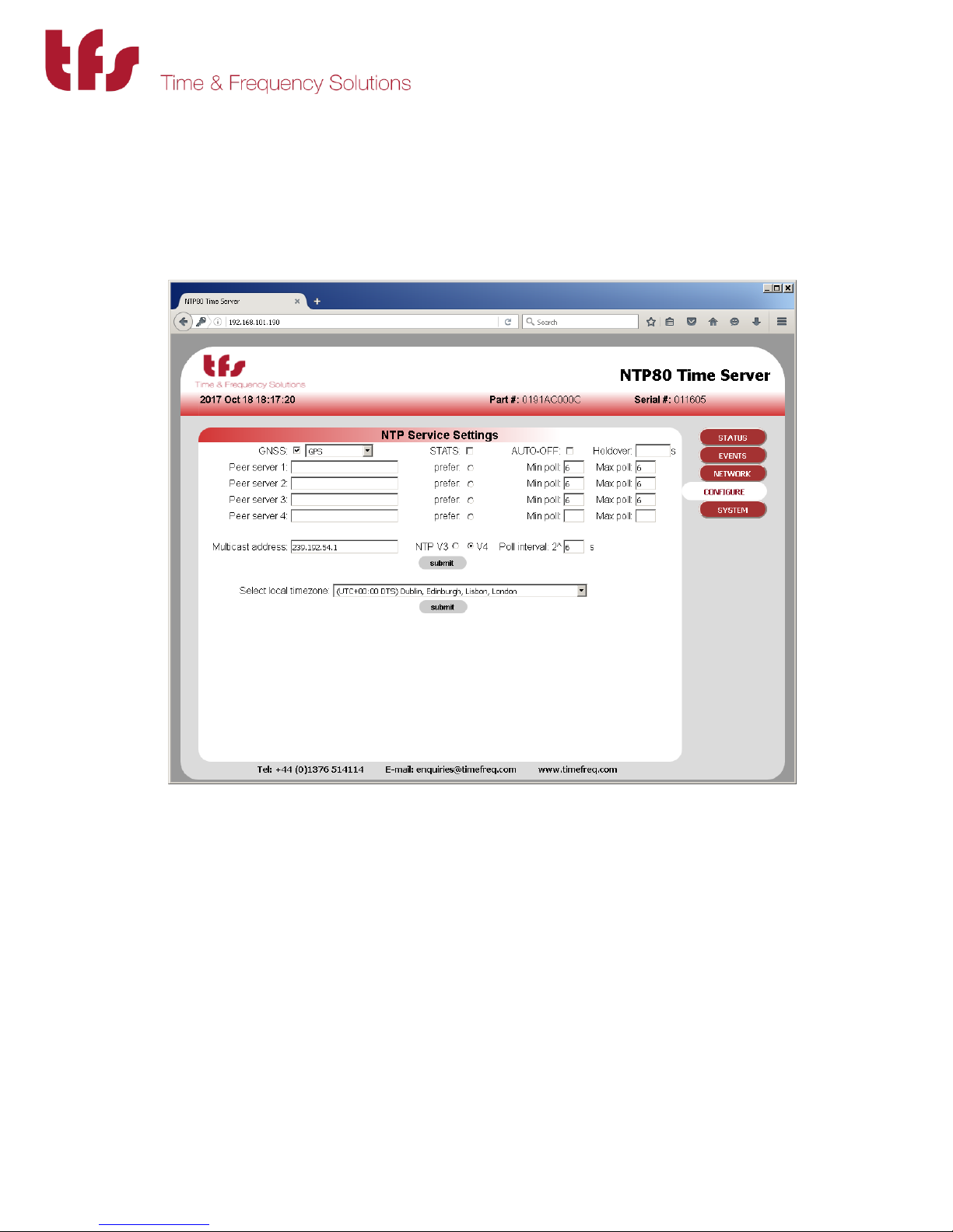
If the unit is a peer to peer only, i.e. it does not have a GNSS receiver, then the CONFIGURE button
will need to selected. For GNSS units the default settings will allow the NTP80 to synchronise
with GPS and provide accurate time.
When in peer to peer only mode, ensure the GNSS checkbox is unchecked, then add the NTP
peers to be configured as peers for this server. The poll intervals are given as power of 2 and
can be from 6 (64s) to 9 (512s).
Press submit to make the changes. Reconfiguration information is displayed. The STATUS button
can be used to return to the status page.
Further details on the NTP configuration can be found in section 5.3
The NTP80 will now be configured and able to serve time on your network.
The following sections give further and more detailed descriptions on configuring and running
the NTP80.
MANUAL P/N 900000165 REV H
Page 15
15
4 NTP80plus Connections
4.1 GPS Antenna Connections (GPS Version)
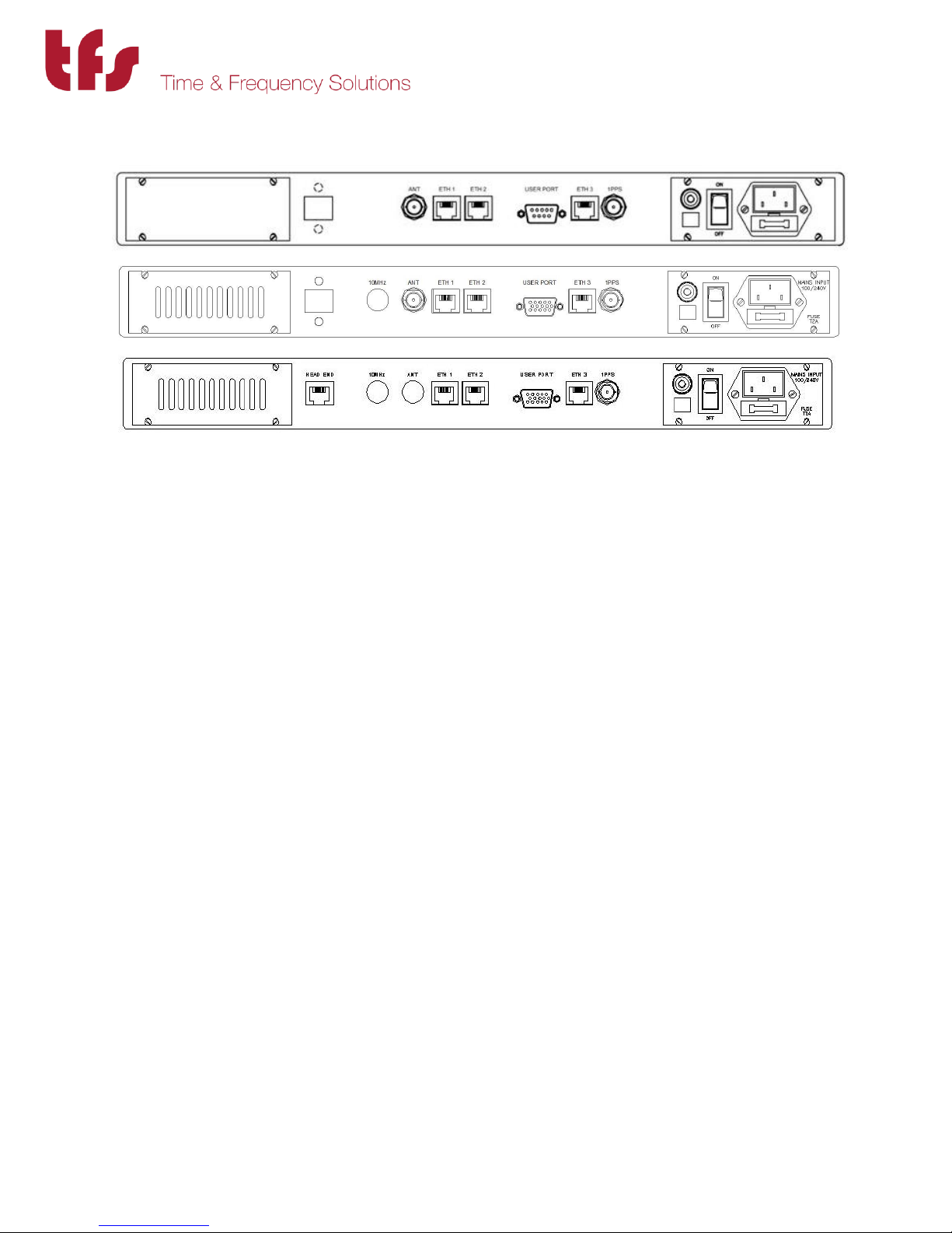
The antenna is connected to the BNC port marked Antenna on the rear of the NTP80. The
antenna connector is a BNC Socket (50 ohm) and its connections are;-
Inner: GPS Signal 1.6GHz (& +5v antenna amplifier power)
Outer: GPS Return.
4.2 GPS Head-End
A remote GPS head-end option is available where the GPS receiver and antenna are combined
at the antenna location. The NTP80plus is fed with a CAT 5 cable connection from the headend.
4.3 1 PPS
The 1 Pulse per second (1PPS) output is derived from the NTP80 internal clock. If you have a
requirement for a 1 PPS you may connect your equipment to this port.
The 1PPS has a positive going on-time edge, at a TTL level.
Note The 1PPS output will be available from initial power on, although it should be noted until
the NTP80 has synchronised the 1 PPS will not be within the quoted accuracy specifications.
Upon synchronisation of the NTP80, the 1PPS will be accurate to the quoted specifications.
The 1 PPS connector is a BNC Socket (50 ohm) and its connections are:
Inner: 1 PPS, Positive going, on time edge, TTL level. (0v to +5v)
Outer: 1 PPS Return.
MANUAL P/N 900000165 REV H
Page 16

16
4.4 User port
The user port is used for system recovery (see Appendix A) and diagnostics. It can also be
factory configured for serial time of day message output. Contact sales for details.
The user port is either a 9 Way D type Socket. Its Pin assignments are shown below:
Serial port 1
Pin 2 Data Out (RS232)
Pin 3 Data In (RS232)
Pin 5 Signal Ground
All other Pins have no function and are open circuit.
Or a 15 way D-sub, In this case dry-contact alarms and an additional RS422 serial timecode
output are provided. The pin connections are as follows:
Alarms Serial port 1 Serial Port 2
pin 1 Power common
pin 2 Power normally closed
pin 3 Data in (RS232)
pin 4 Data out + RS422
pin 5 Signal Ground
pin 6 Status common
pin 7 Status normally closed
pin 8 Data out (RS232)
pin 9 Data out - RS422
pin 10 Data in + RS422
pin 11 Sync common
pin 12 Sync normally closed
pin 13 Signal Ground
pin 14 Data in - RS422
pin 15 Signal Ground
Serial port 1 has a configuration depending upon any factory configured serial time-of-day
message. Without this serial message the port configuration is
115.2baud, 8 bits/char, no parity, one stop bit,
Serial port 2 when enabled has a fixed configuration of
4800 baud, 8 bits/char, no parity, one stop bit.
The message can be one of the following and the same on both ports:
GPRMC
TFS Message 1, byte sequence:
centiseconds sec min hour weekday day month year 0 0 0x3f 0xff
MANUAL P/N 900000165 REV H
Page 17

17
all time/date values are in BCD.
Alarm connections
Label Activity Remarks
power closed Power is supplied to the NTP80
open Power is off
status closed System is operating normally
open System is not operating normally
sync closed Unit has loaded and serving time
open Unit has not loaded
4.5 100 BASE T Ports
Three independent Ethernet ports are available for interfacing into your network and use
standard Ethernet RJ45 connections. The unit is also configured and monitored via a web GUI
through a network connection.
4.6 Power Connection
The AC mains connector is suitable for 90-240V AC at 50/60Hz.
MANUAL P/N 900000165 REV H
Page 18

18
5 Web-based configuration
The main configuration method is via the web interface. There are
five screens, two for status information and three for configuration.
Access to any of these is via the navigation bar shown right.
The three pages that configure the unit are
Network Set the network configuration for each of the three Ethernet ports and also the
SNMP parameters.
Configure Set up the NTP operating parameters along with the local time zone.
System Set up the web security to access the NTP80plus.
The NTP80plus is delivered with the web security enabled so access the unit for the first time
requires entry of the default username and password.
Default username admin
Default password ThePassword
These are case sensitive.
Access the NTP80plus with any browser, providing the above credentials and select the SYSTEM
page from the navigation menu.
MANUAL P/N 900000165 REV H
Page 19
19
5.1 System Security
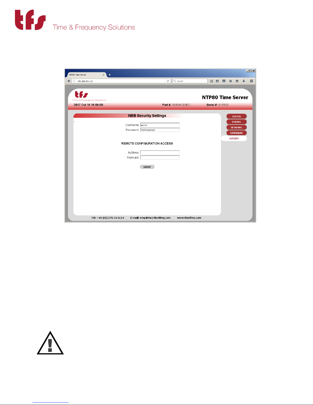
The login credentials, username and password, are set here. If they are removed then the
security is disabled. Do not lose these details. If they are lost then the unit will have to be
restarted and the factory defaults restored using the user interface port.
The remote configuration access limits access of the web interface to an IP address or a range
of IP addresses. Be extremely careful when setting these values since it is possible to lock out all
access. The address and the subnet mask MUST agree.
To restrict access to a subnet, for example 192.168.101.x then 192.168.101.0/255.255.255.0
can be entered for the address and netmask. For the default factory network settings this
would mean that only users on port ETH1 could access the web interface.
To restrict access to a single host, for example 192.168.101.1 then
192.168.101.1/255.255.255.255 can be entered for the address and netmask. Then only this
host can use the web interface.
CAUTION
There must not be any discrepancy with subnet mask and IP address, for example
if 192.168.101.1 had been entered with a subnet mask of 255.255.255.0 all access
would be denied as there are no addresses that can meet this configuration. To
recover from lock-out the unit will have to be restarted and the factory defaults
restored using the user interface port.
MANUAL P/N 900000165 REV H
Page 20
20
5.2 Network Configuration
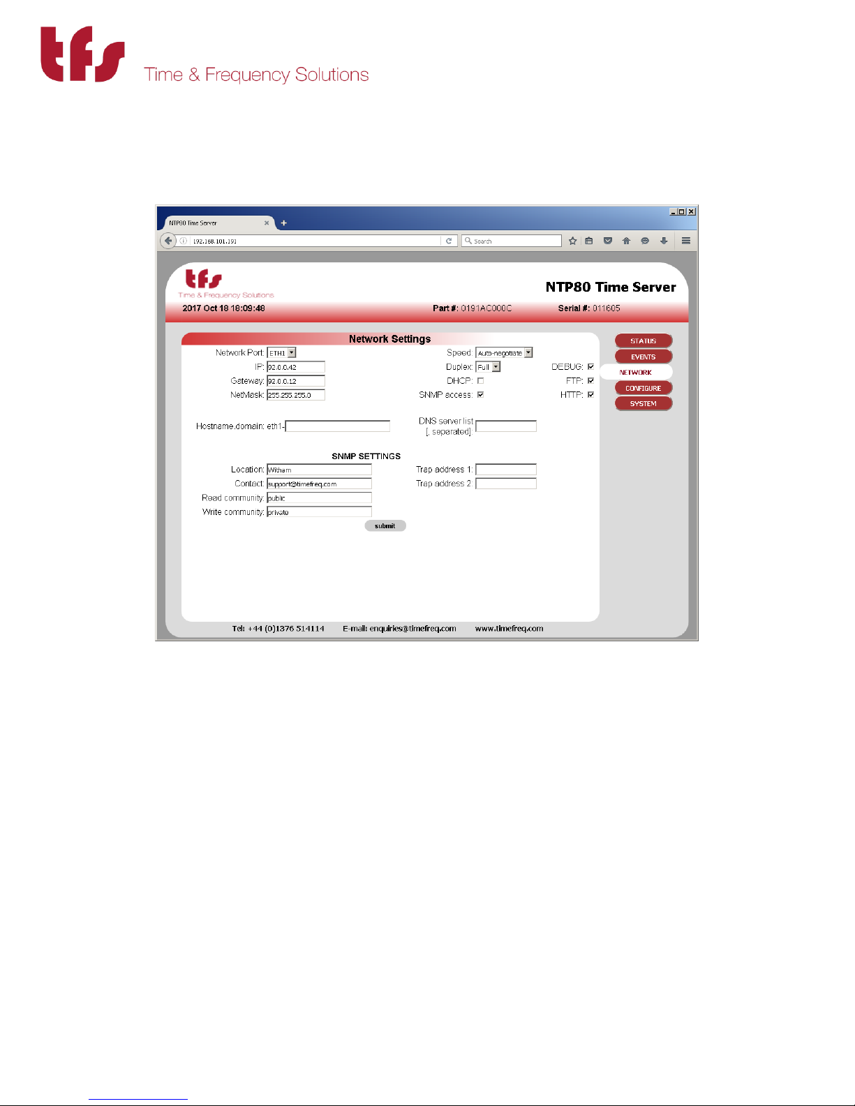
This page allows the configuration of each of the Ethernet ports. Select the port to configure
from the drop down list box. The current settings for that port will be shown.
The following settings are port specific:
IP , Gateway, Netmask, Speed, Duplex
DHCP - Permit port to acquire its address via DHCP. This will be shown on the status
page.
Hostname - The unit can be provided with a hostname for DHCP enabled ports. If changed
or set independently of the DHCP flag, it must be submitted for each of the
ports that DHCP has been enabled for.
SNMP Access - Allows SNMP queries and traps to be generated.
HTTP - Enable the web service on this interface. Note that it is not possible to disable
the web interface from all ports with this setting.
FTP - Allow firmware updates
Support - Allow remote access for factory support if there are any problems. This is not a
user accessible interface
Note that any changes must be submitted prior to changing the port selection otherwise they
will be lost. This includes the non-port specific settings.
MANUAL P/N 900000165 REV H
Page 21
21
The following settings are not port specific:
DNS server list - comma separated list of DNS server IP addresses.
SNMP parameters - These are effective on the ports that have SNMP access enabled.
The NTP80 will send traps when a trap address is set. There are rules as to where these traps
will be sent depending on the port configurations.
If the trap address is on a subnet of a particular SNMP enabled port then the trap will only be
sent to that port. If the trap address is not on any subnet of the defined ports then the trap will
be sent to all SNMP enabled ports that have a gateway address defined. If the network is such
there are two routes to the trap address destination it will be received twice.
The NTP80 routing is such that all ports are isolated from each other.
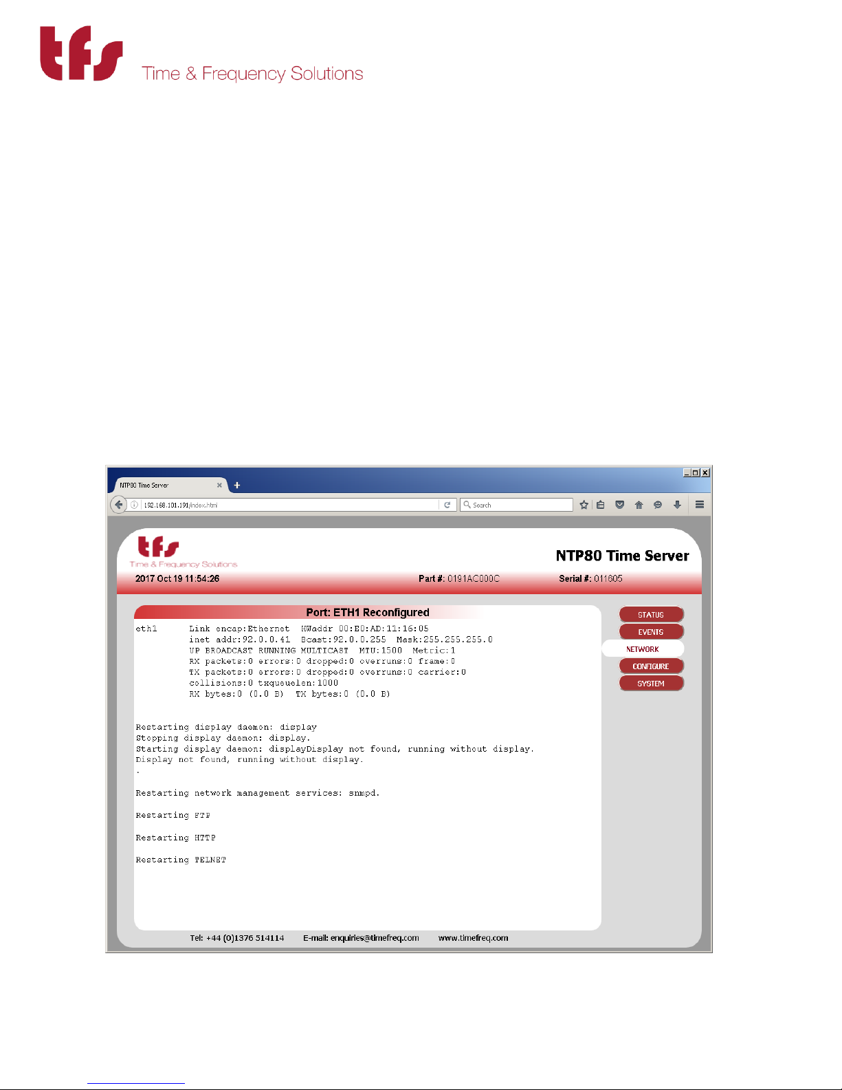
Pressing Submit will apply the changes.
MANUAL P/N 900000165 REV H
Page 22
22
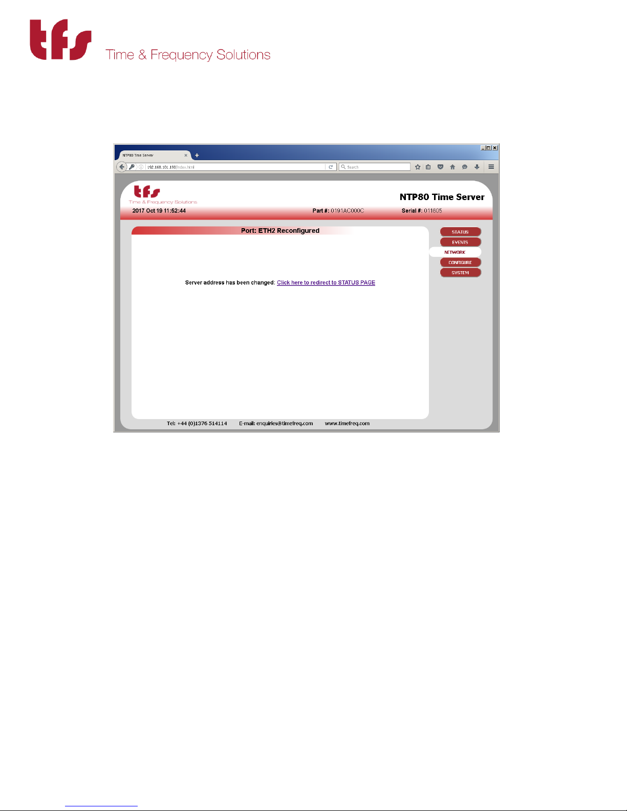
Note that if you change the IP address of the port through which the web page is being
accessed the following will be shown, the link ‘Click here to redirect to STATUS PAGE’ is created
to connect to the new address. The navigation panel at this point will not work as it has links to
the old address.
MANUAL P/N 900000165 REV H
Page 23
23
5.3 Configure, NTP Configuration
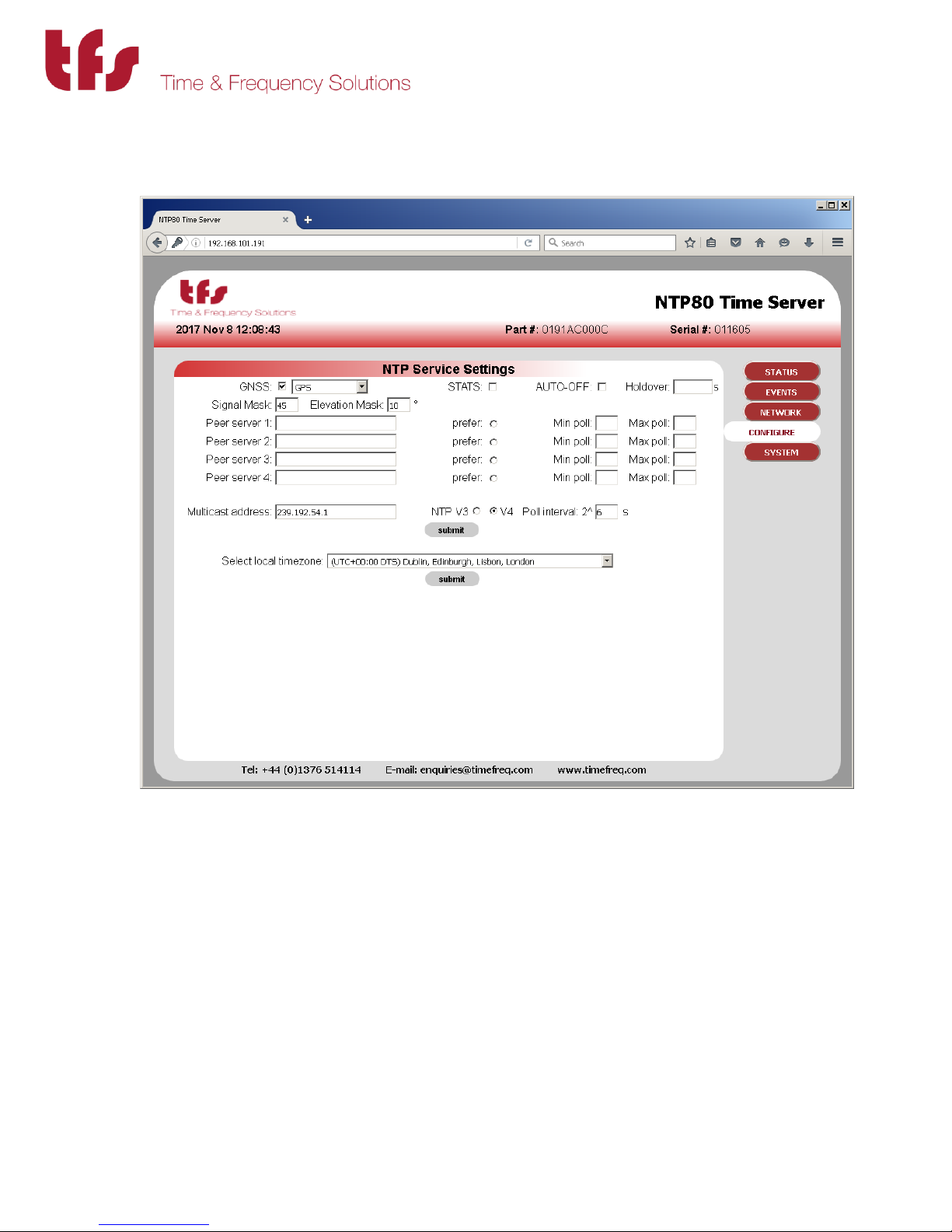
This page sets up the NTP service.
For the NTP80 with a GNSS receiver the GNSS checkbox must be ticked. The drop down list
selects the GNSS constellation used for resolving time. This is after position is resolved in which
all satellites in all constellations will be considered.
The constellation choices are: GPS, GPS+GLONASS, GPS+BEIDOU, GLONASS, BEIDOU.
The tracked satellites on status page will show the satellites used in each constellation.
STATS
This is used for diagnostic purposes and should normally NOT be enabled.
MANUAL P/N 900000165 REV H
Page 24

24
AUTO-OFF / Holdover
This provides a mechanism for non-standard NTP or SNTP clients that do not properly adhere to
NTP protocols such as RFC1305. In particular where the leap indicator flags are not used or the
monitoring of reference time is not taken into account. For these situations the auto-off
mechanism will stop the NTP80 servicing NTP requests after a period specified, in seconds,
from the time that synchronisation is lost. Initially when this is enabled the holdover time will
be set to 86400s, i.e. 24 hours. This will mean that any NTP client will not be able to use this
server after this time regardless of how that client is implemented. Note that the Holdover time
specified should take into account the oscillator that is fitted to the NTP80. The reliability of
time will be greater for longer for a Rubidium unit than one with a TCXO. All can be within the
NTP Stratum 1 specification of 1ms after 1 day of holdover assuming good GPS reception for a
significant period of time prior to loss of synchronisation.
Signal Mask
A signal level value below which satellites ignored for timing, 0 – 55. The default value is 35,
reduce this if there are problems with GNSS synchronisation.
Elevation Mask
Elevation below which satellites will not be used for timing. The default value is 10°.
Peer Servers 1-4
If the NTP server is a peer-to-peer model, with no GPS fitted, then the GPS checkbox must not
be ticked. The configuration then allows for up to four NTP servers to synchronise with. These
are specified in Peer server 1 to 4. They can either be a DNS name or an IP address. The min and
max poll indicate the minimum and maximum rate of NTP requests. This number is a power of 2
and can be from 6 to 9, so the standard minimum poll interval is 26 = 64s and the maximum is
29 = 512s. If these fields are left blank then the NTP service will decide on the appropriate
polling interval.
The NTP server follows the standard NTP protocol to determine the best of the specified clocks
to synchronise to. One may be selected as preferential by setting the prefer option radio button
for that server.
The peer NTP servers can also be set up with a GNSS unit. These can then take over following
the loss of GPS synchronisation. Note that depending on the oscillator fitted and the period for
which GPS is lost, the performance when synchronising to another NTP server will not be as
good as running in holdover. If peer NTP servers are available in this configuration the AUTOOFF will not function until all possible synchronisation sources have failed.
Mulitcast (or Broadcast) Address
The NTP80 can be used as a broadcast NTP server. A broadcast address or multicast address can
be specified in the multicast address box along with the poll interval. The unit will then transmit
NTP messages at this interval to the multicast or broadcast address.
MANUAL P/N 900000165 REV H
Page 25
25
For network-wide broadcast the address would be 255.255.255.255, for a subnet set the host
part of the address to the last host address, so for network 192.168.101.0 that would be
192.168.101.255
The above parameters are applied when submit is pressed. This will stop and re-start the NTP
service.
Local Time Zone
The local time zone allows the front status page and the front panel display to show local time
rather than UTC. Note that all NTP operations are performed with UTC. Setting this parameter
has no effect on NTP operation. The factory configured GPRMC serial output options of the
NTP80 provide a local-time message, that local time is also defined by this parameter.
Press submit to change this value.
The NTP80 is now configured.
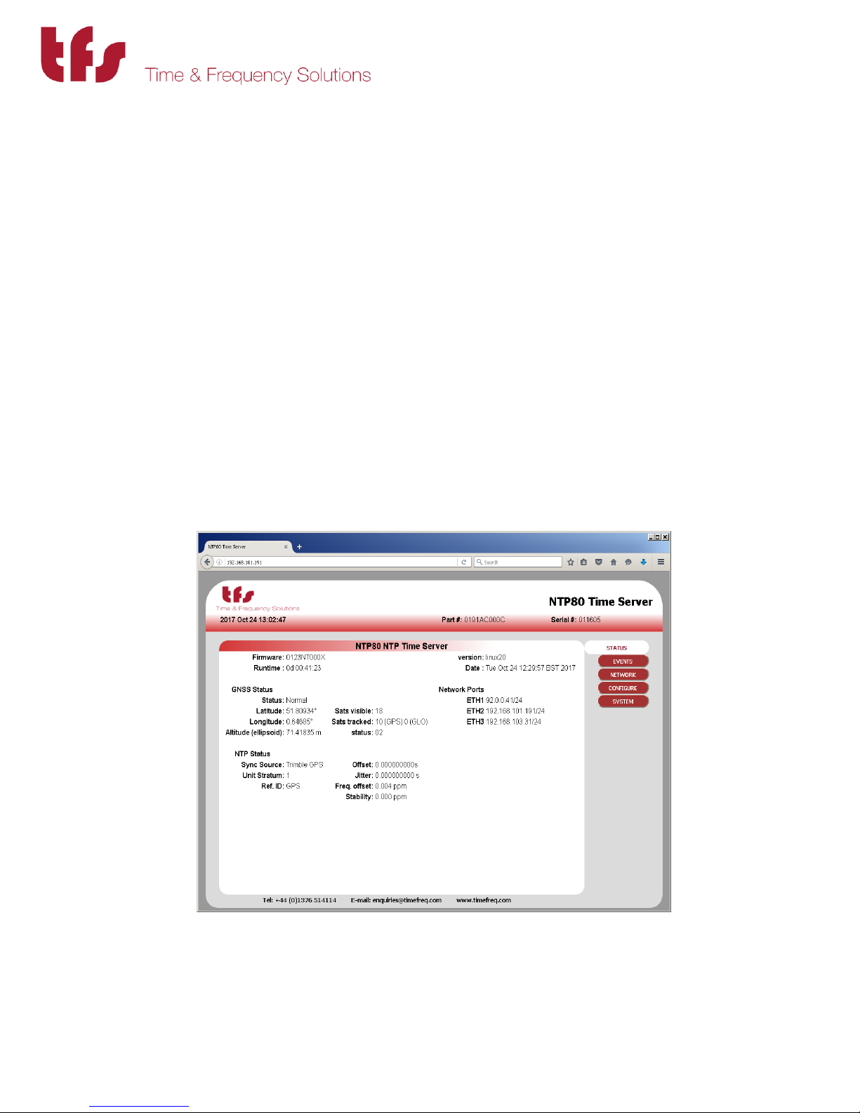
5.4 Status
The status page shows the current running state of the NTP80. The top section shows the
system state including how long it has been running and the currently loaded date and time.
The GNSS status shows position and the satellite status. The top status will reflect the condition
determined from the status number. This status is recorded in the event log. See Events for
details.
MANUAL P/N 900000165 REV H
Page 26

26
The status number has the following meaning
00,01,02,03: These are all valid. For normal operation this will be 2
04,06: indicates no time is set
08,0A: indicates there is no UTC information
0C,0E: no time and no UTC information
Where multi-constellation mode has been selected then the satellites tracked from each
constellation are identified.
The NTP status indicates the current NTP service synchronisation source and the stratum level.
For a GPS unit these would normally show GPS engine and stratum 1. For a peer-to-peer server,
the Sync Source will show the IP address of the synchronisation source and the NTP80 stratum
will be dependent on the stratum of that source. Sync source will also show the status of the
NTP service when not synchronised. These events are recorded in the event log. If the unit is in
holdover the status will state NO SYSTEM PEERS. See Events, below, for further details.
Offset, jitter, freq offset and stability indicate the performance of the NTP service. The closer to
zero these values, the better the performance.
The page updates automatically every 10s.
The events that are shown in the status page are recorded in the event log and can be seen by
selecting EVENTS from the navigation panel.
MANUAL P/N 900000165 REV H
Page 27
27
5.5 Events
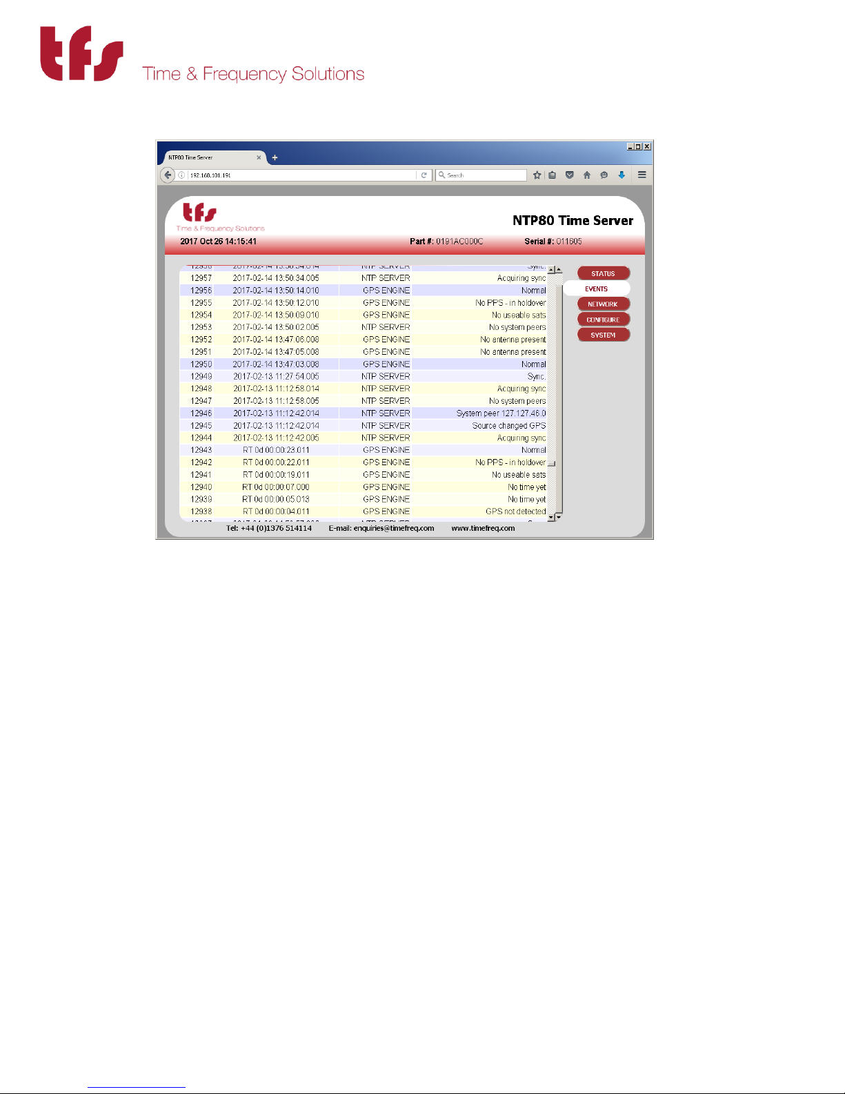
The event page shows all the recorded events from the GPS engine and NTP server parts of the
NTP80. The example above shows a typical start up sequence from event id 12938 to 12949.
The time shown is the NTP80 time, so if the local time zone has been set on the configure page
then this will be NTP80 local time. RT indicates run-time, this is before the NTP80 has loaded
time from a source. Following GNSS acquisition (12938 to 12943) the NTP service starts to
synchronise to the GPS engine (12944 to 12948) and finally the NTP service is fully operational
(12949). The event log is maintained through power fail and will record around the last 800
events.
MANUAL P/N 900000165 REV H
Page 28

28
The following lists all the events and their causes that can appear in the event log. They will
cause an SNMP v1 trap to be sent to SNMP enabled ports. GPS events are also shown on the
front panel of the NTP80, and these events will be shown in the relevant status field on the web
status page.
The events are divided into three sections. SYSTEM, GPS and NTP.
SYSTEM
System startup. Initialisation of event log. Not visible after first 800 events.
Manual restart Remote reboot has been applied.
GPS
Normal GPS operating normally.
No PPS - in holdover GPS not tracking – NTP80 in holdover.
PDOP too high Tracked satellite constellation too poor for good position
resolution. NTP80 in holdover.
Only 3 usable sats
Only 2 usable sats Satellites tracked, requires at least 4 for time to load
Only 1 usable sat initially.
No useable sats
No time yet GPS start up.
Antenna shorted There is a fault with the antenna connection.
No antenna present No antenna is connected. Check antenna is connected.
Not detected Initial start-up condition.
All the above are decoded from the status value visible on the web page and relate to the GPS
operating status. If all is well then the last event will be Normal. Any single event will be cleared
by returning to Normal - so if the antenna is disconnected then the minimum event sequence
will be 'No antenna present' and then after reconnection 'Normal'. In reality some intermediate
messages will occur as the number of satellites tracked increases. In most cases, if any state
other than normal is seen persistently then the likelihood is that there is an issue with the GPS
reception either due to antenna placement, operation or cable length.
MANUAL P/N 900000165 REV H
Page 29
29
NTP SERVER
Sync. Synchronised to source & serving time.
System peer <ip address> Synchronisation source found. When this is the GPS
engine the IP address will be shown as 127.127.46.0
Acquiring sync Locking to time source
No system peers no valid synchronisation sources. Unit in holdover.
NTP suspend NTP service suspended & will no longer answer NTP
requests. Part of the AUTO-OFF process.
NTP resume NTP service resumed. Part of the AUTO-OFF process.
Initialising Indicated on web status page only at startup before initial
time is loaded. This status is not logged and does not
cause a trap.
As long as there is a system peer then there should be no problem with the NTP service. If “no
system peers” is seen with a GNSS receiver then the GPS status will indicate the problem (see
above) otherwise with the peer-to-peer model the network connection to specified NTP servers
should be checked.
There is one other trap that can be issued, the cold-start trap. This will appear to be issued from
the ETH2 address.
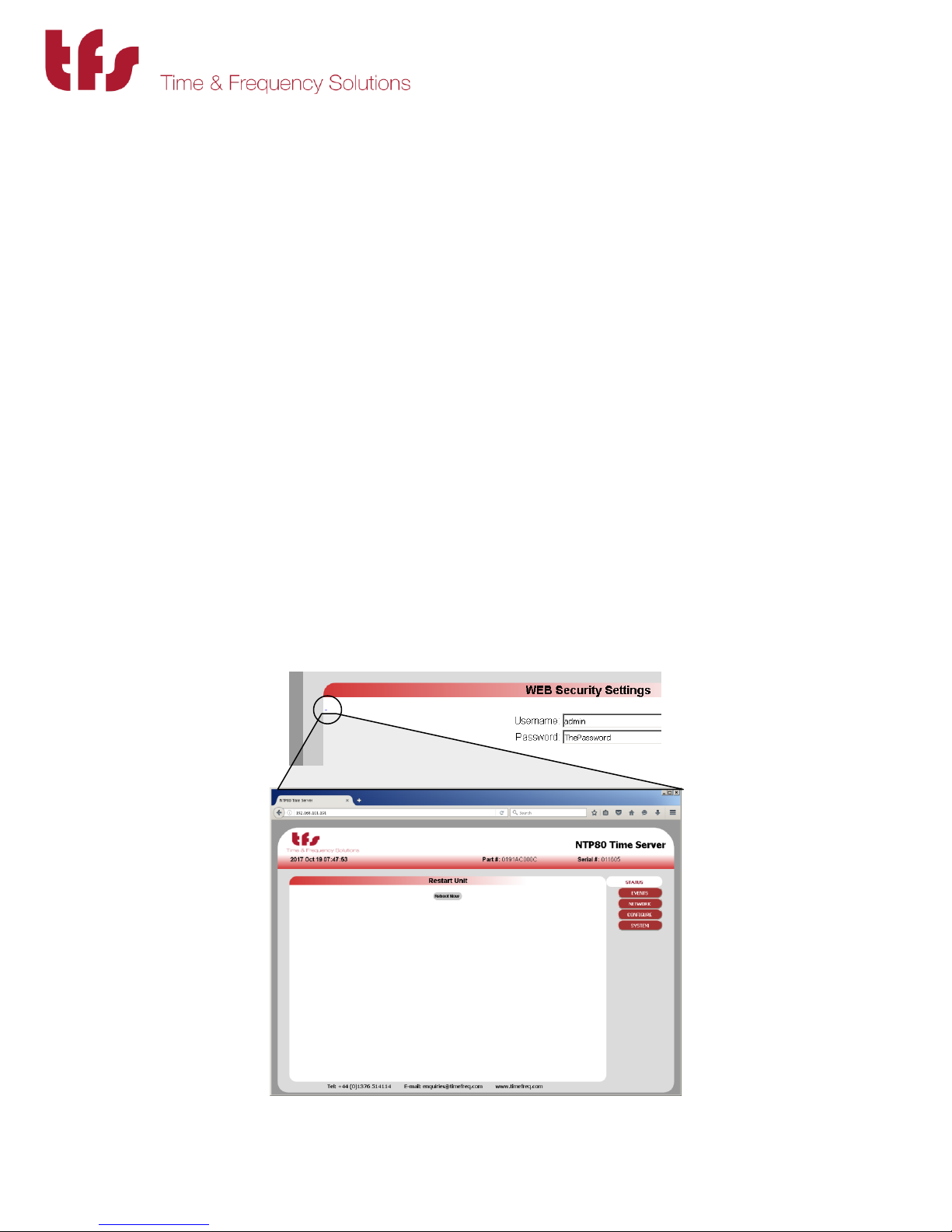
5.6 Remote restart
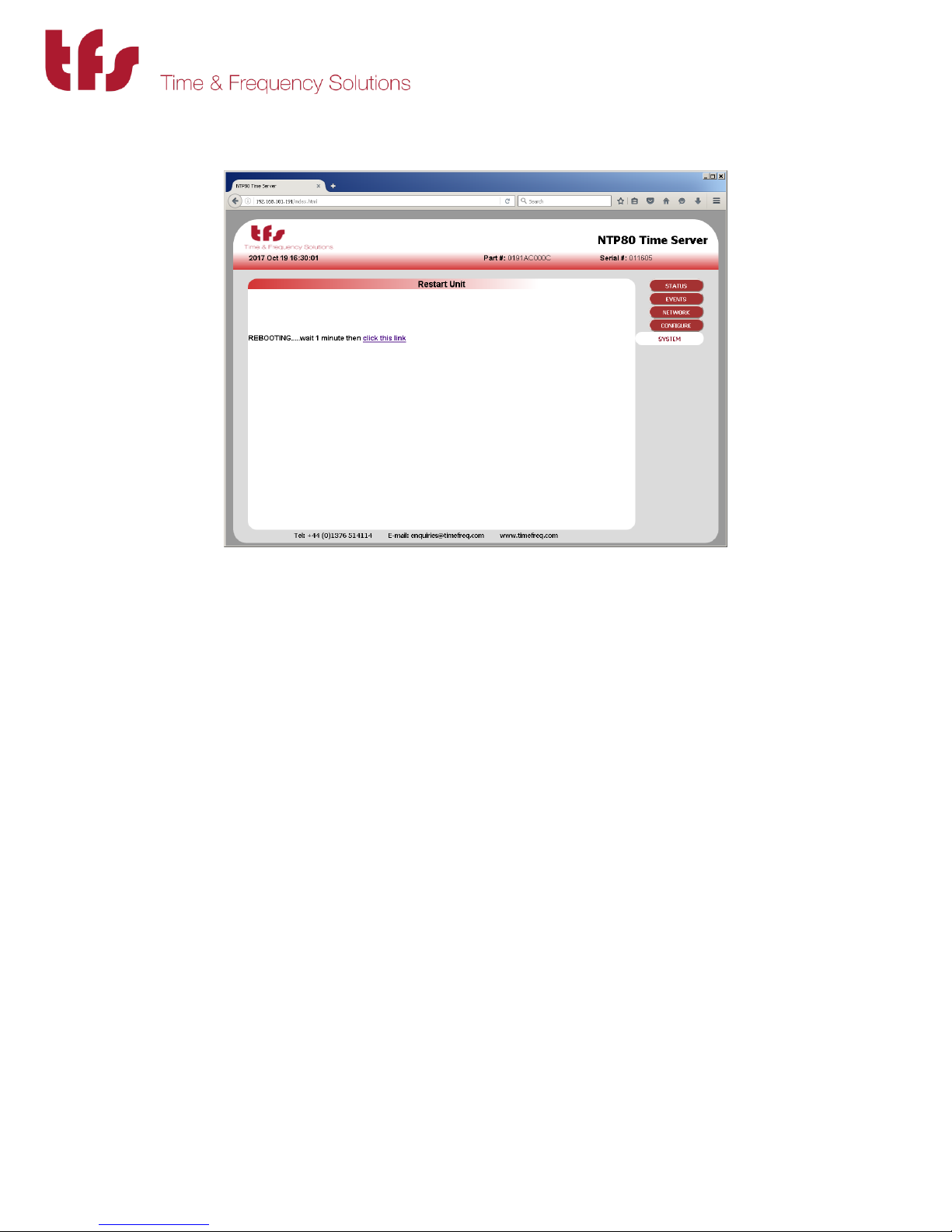
There is a mechanism to remotely reboot the NTP80. From the SYSTEM page notice the small
‘_’ on the top left side of the page.
MANUAL P/N 900000165 REV H
Page 30
30
Pressing the reboot now button will cause the unit to do a complete restart. It will take
approximately 1 minute to reboot.
Clicking the link shown will take you back to the status page. The reboot is recorded in the
event log.
MANUAL P/N 900000165 REV H
Page 31

31
6 Front Panel Setup & Status.
With the NTP80plus switched on and connected to a GPS signal a typical status display would
show:
GPS Tue Nov 27 16:29:38 2012
9 GPS 5 ST: Normal
This indicates that the unit has time from GPS and that the GPS signal is normal. The second
row indicates the number of visible satellites as the first number on the left followed by the
tracked satellites in the selected constellations. In this case just GPS is selected. The selection
will be shown on the top line.
GPS+GLONASS Tue Nov 27 16:29:38 2012
9 GPS 5 GLO 3 ST: Normal
The configuration menu structure is (left of | shows down path, right for up path)
Main
-------------OK-------------------- |^ |^
< Date/Time > < Ethernet >
OK| OK|
Edit Date/time ------------------------------------------------------(if permitted) |^ |^ |^
< ETH1 > < ETH2 > < ETH3 >
OK|^ OK|^ OK|^
ETH1 display ETH2 display ETH3 display
OK|OK(save) OK|OK(save) OK|OK(save)
Edit ETH1 Edit ETH2 Edit ETH3
So to configure the Ethernet ports from the front panel follow the sequence below, using the
keys up, down, left, right and OK.
From the main display (show above) press OK
Main > Date/Time
[OK-enter] ->
MANUAL P/N 900000165 REV H
Page 32

32
So to modify the ETH2 port configuration the following sequence should be followed:
Press left
Main > Ethernet
<- [OK-enter]
Press OK [OK-enter]
Main > Ethernet > ETH1
[OK-enter] ->
Press left [OK-enter]
Main > Ethernet > ETH2
<- [OK-enter] ->
Press OK, this shows the current configuration for port ETH2. This shows, on line 2, port name,
and the IP address. The netmask is shown as a bit count rather than in the dotted notation. In
this example 24 means 255.255.255.0, i.e. 24 set bits in the mask. Finally on the line is the
gateway address.
[OK-enter]
ETH2 Current config. [OK-edit] [^ exit]
ETH2 192.168.102.99/24 192.168.102.34
Press OK to modify this configuration. The following display is shown. The Left/Right keys cycle
through fields, the field selected is indicated by an underline on its first character. The up/down
keys change values. OK will exit except without saving changes except when save is selected
first, then changes will be applied.
ETH2 Edit [OK-exit/save </>-sel ^+/V-]
192.168.102.098/24 192.168.102.034 SAVE
ETH2 Edit [OK-exit/save </>-sel ^+/V-]
192.168.102.098/24 192.168.102.034 SAVE
Selecting SAVE then pressing OK applies the changes:
ETH2 Edit [OK-exit/save </>-sel ^+/V-]
Updating port ETH2
MANUAL P/N 900000165 REV H
Page 33

33
Menu will return to Current config, showing the now updated address information.
[OK-enter]
ETH2 Current config. [OK-edit] [^ exit]
ETH2 192.168.102.98/24 192.168.102.34
Press the up key to exit this menu. If after a short period a key has not been pressed the display
reverts to the main status display. Ensure that the unit is not left unattended in the port edit
page.
The GPS status information that can be shown on the front panel is shown below. This is an
example power up sequence following on front the NTP80plus identification message at the
start.
Example GPS start-up sequence…
Run-time: 0d 00:01:00
12 GPS 0 ST: No GPS time yet
Run-time: 0d 00:01:53
12 GPS 1 ST: No usable sats
Run-time: 0d 00:02:10
12 GPS 1 ST: Only 1 usable sat
Run-time: 0d 00:02:23
12 GPS 2 ST: Only 2 usable sats
Run-time: 0d 00:02:31
12 GPS 3 ST: Only 3 usable sats
There may be other messages during this sequence.
Run-time: 0d 00:05:00
12 GPS 4 ST: Normal
MANUAL P/N 900000165 REV H
Page 34

34
Finally loaded time & default display.
GPS Tue Nov 27 16:29:38 2012
9 GPS 5 ST: Normal
Other possible status messages are:
Antenna not connected
GPS Tue Nov 27 16:29:38 2012
12 GPS 0 ST: No antenna present
Antenna connection fault
GPS Tue Nov 27 16:29:38 2012
12 GPS 0 ST: Antenna shorted
All other status messages are detailed in the Events section of Web Management above.
MANUAL P/N 900000165 REV H
Page 35

35
7 Working with the TFS Network Management System
The status of the NTP80plus will be shown on the status tab for the particular time server.
There are five sources of possible alarm states. These relate to the status elements NTP overall
state, GPS system state and the ETHx ifOperState for each port.
For the NTP overall state the following will indicate a fault and turn the indicator red:
NTP not loaded NTP not loaded will be the case at start up, prior to first time
synchronisation. After this, unless the NTP service is reconfigured this
alarm will not be set.
NTP GPS no GPS Not synchronising to GPS. Check GPS status for reason. This will be
permanently set with a Peer-to-peer NTP80plus but will not cause an
alarm.
NTP Peer to Peer no peer
Disabled for GPS NTP80plus. For peer to peer NTP80plus indicates that
NTP service has no peers to synchronise to and will therefore cause an
alarm.
NTP service not present.
NTP service fault. Consult Time & Frequency Solutions.
MANUAL P/N 900000165 REV H
Page 36

36
For GPS system state (applicable only to GPS NTP80plus) alarms caused by:
Time Not loaded NTP80plus GPS engine has not yet loaded time. Should only occur at
start-up of NTP80plus. After time has been set the alarm will clear. It can
then never be set again without power-down.
GPS Acquiring sync
GPS is not currently synchronised. The likelihood is that there are not
enough tracked satellites.
GPS Not present Should only occur and NTP80plus start-up.
For ETHx:
ifOperStatus down Network connection is not active. Check connectivity.
MANUAL P/N 900000165 REV H
Page 37

37
8 Understanding the Network Time Protocol.
8.1 Why use the Network Time Protocol
Accurate Time has always been an important issue, especially in today’s world where computer
systems are required to precisely time stamp events and occurrences. However, computers are
notorious for poor time keeping because they use a basic watch crystal as their internal timebase.
This means that the computer’s internal clock will drift significantly over time, an effect
exacerbated by changes in temperature. A computer in an office environment can lose or gain up
to 40 seconds in a week.
Computers are normally set manually to a known time source such as a speaking clock or
broadcast time signal. Once set, most users leave the computer timebase to drift, resetting the
operating system clock only on an ad-hoc basis.
Network Time Protocol (NTP) is an Internet Protocol, which propagates time throughout the
network and is referenced to UTC. The NTP Time Server acquires UTC time by a direct UTC time
scale source, such as GPS. Other options such as IRIG or LF receiver are available.
MANUAL P/N 900000165 REV H
Page 38

38
Server
Timeline
Client
Timeline
T2
(Receive)T3(Transmit)
T4T1
(Originate)
8.2 Understanding NTP
The client computer obtains the NTP protocol by requesting a NTP packet from the NTP Server.
The Software that requests the packet handles reception, maintenance and distribution of the
time on the computers where it is installed. All Time & Frequency Solutions NTP Time Servers
are supplied, with client software as standard for a range of operating systems & platforms.
Most client software compensates for the delays over the network, and synchronises the
computers with an accuracy of typically 1ms to the NTP Server. For larger networks such as
WANs delays of up to 10ms can be expected.
Figure 1 – Basic Method of Delay Calculation Over a Network
Another commonly used protocol is the SNTP (Simple Network Time Protocol). As the name
suggest this is a simpler way of obtaining time over a network, but this method does not
compensate for delays and therefore is not as accurate.
All Time & Frequency Solutions supplied client software uses the NTP protocol, and therefore
provides a more reliable solution than SNTP.
MANUAL P/N 900000165 REV H
Page 39
39
8.3 NTP Hierarchical Structure
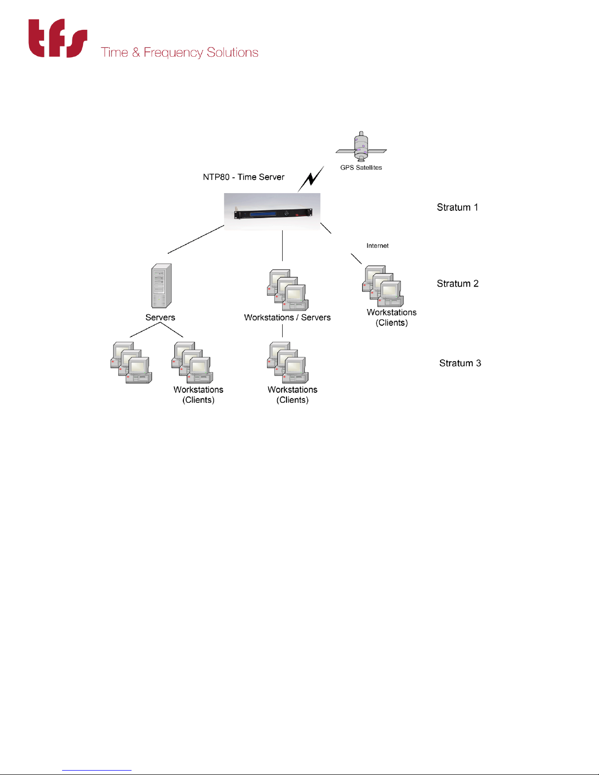
The NTP protocol supports a hierarchical structure to ensure the availability of time, allowing the
user to monitor their position in the hierarchy and thus the quality of the time service available.
Figure 2 – Explanation of Hierarchical Stratum Structure
The timeserver’s hierarchy is classed as Stratum, where a Stratum 1 time server that is directly
synchronised to a traceable standard source such as UTC. A server synchronised to a Stratum 1
server is classed as a Stratum 2 server, and so on. This hierarchical structure allows sub
partitioning of groups of networks.
Up to 512 Computers may synchronise to a single NTP80plus Time Server. We do not recommend
increasing the number of clients beyond this limit, as the performance will become degraded due
to non-responses.
MANUAL P/N 900000165 REV H
Page 40

40
9 Frequently Asked Questions
The following is a list of commonly asked questions by our customers. If the question that you
wished to be answered is not in the list please contact us. Contact details are found at the end
of this manual under Chapter 11.
Q Can the NTP80plus act as a stratum 1 server?
A Yes, Once the NTP80plus has synchronised to a traceable GPS or Off-Air source it will
automatically become a stratum 1 server. In the event of loss of synchronisation this will
be maintained for up to 24 hours at stability in accordance with the internal oscillator
specified.
Q What packet types will the NTP80plus respond to?
A ARP requests - to find Ethernet addresses given the TCP/IP address.
ICMP echo requests - to allow ‘pings’ of the NTP server.
UDP connections to port 123 – the defined NTP server port, SNMP V1, V2c
TIME & DAYTIME (port 13 and 37)
FTP for firmware update.
No other packets are accepted.
Q Can a client have two sources of stratum 1 server so if one server loses the time or is
offline the client can receive time from the second server?
A Yes, in most cases the client software will allow the configuration for two IP addresses;
one IP address will be the “preferred” server.
Q How do I know if the NTP80plus is free running? ie the NTP80plus has synchronised to
GPS at some point but has now lost synchronisation?
A The webpage status and the NTP80plus front panel will indicate that the GPS status is
no longer Normal. The “STATUS” LED on the NTP80plus will be off.
Q What causes the NTP80plus – GPS Version to loose synchronisation and free run?
A If the installation of the GPS antenna was originally correct, free running is commonly
caused by the faults such as GPS cable feeder integrity or Water ingress to the antenna
or feeder cable
MANUAL P/N 900000165 REV H
Page 41

41
Satellites’ visibility has been reduced through new building structures, or the new
installation of other equipment above the antenna.
Q How many Clients may I connect to one NTP80plus Time Server?
A The NTP80plus can handle up to 512 packets per second, which equates to a theoretical
512 x 64 (32,000+) clients assuming standard NTP operation. We do however recommend
not exceeding 1000 clients as good practise in designing NTP networks. If more clients are
used in heavy traffic then not all packets will be answered.
Q I am not using the Time & Frequency Solutions Network Management System and using a
third party software package. Where can I obtain the SNMP trap information?
A See Appendix B for the SNMP MIBS for the NTP80plus.
MANUAL P/N 900000165 REV H
Page 42

42
10 Troubleshooting Guide
Here are a few common problems that occur with their likely causes. If these answers do not
help you, then please contact us to help us resolve your problem. Contact details are found in
Chapter 11.
Q Unable to obtain Time from the server?
A If the NTP80plus STATUS LED is blue and the display shows Normal, check that you are
using the correct software. Some synchronising software looks for a NTP broadcast
message, if this is the case, ensure the NTP80 broadcast address is configured correctly.
Q Unable to ‘Ping’ NTP Ethernet module?
A1 If the unit fails to respond to a ping test, check that the TCP/IP address has been
correctly set. Check that the correct interface port has been attached to the network.
Check the Ethernet connection between your NTP80 and Hub or network connection.
The Link LED on your NTP80 Ethernet Port and the corresponding network connection
LED should both be illuminated.
A2 If you have recently changed the NTP80’s IP Address and have been communicating
with the NTP80 across the network then don’t forget to clear the “arp” table for the
appropriate MAC address. This can be implemented by typing arp –d < IP Address > at
the command prompt.
Q Module does not appear to see NTP packets but works with a ping?
A1 An NTP80 that pings, does not necessarily mean that a client’s NTP requests for NTP
packets will respond. If a firewall is installed between the NTP80 and the Client, check
that the Firewall settings will allow NTP packets to flow in both directions. Confirm that
the Gateway address has been specified in the configuration correctly.
A2 If the unit fails to respond to an NTP packet, try using NTPDATE or a similar program to
establish communication. Check the client machine is able to send UDP packets on port
123 (the defined NTP port number).
MANUAL P/N 900000165 REV H
Page 43

43
A3 Confirm that the NTP80 has not been free running for a long period. Free running occurs
when the NTP80 has gained synchronisation and then lost it again. The NTP80 must be
synchronised for the NTP to function correctly. Check the web status page to ensure
that GPS status is normal and NTP status indicates GPS engine as the synchronisation
source. NTP software may use another NTP server after approximately 24 hours of the
original NTP server losing its synchronisation.
Q Unreliable connections between the NTP80 and the LAN
A Confirm that you are using proper cables. With 10BASE-T connections, you may use
Category 3, 4, or 5 cables. We recommend the use of CAT-5 patch cables (straight
through)
MANUAL P/N 900000165 REV H
Page 44

44
11 Specifications
Model Number: NTP80Plus (Rackmount Version)
Size: 19” Rack Mounting, 1U High, 200mm Deep
1.5kg typical
Power: 90-264V AC, 47-63Hz, Load 20W
Synchronisation
Source: GPS , GPS+GLONASS, GPS+BEIDOU, GLONASS, BEIDOU
Input Level: +11dB to +35dB
Synchronisation Accuracy: ± 100 nanoseconds from UTC with Signal availability.
(Assuming adequate satellite visibility)
1PPS Output
Connection: 50 BNC socket
Output: 1 pulse per second upon synchronisation.
Level: TTL
Edge: Positive
Accuracy: ±2 microseconds from UTC with Signal availability.
(Assuming adequate satellite visibility). Accuracy stated
after 30 minutes from synchronisation.
Network Connection
Connection: 3 x RJ45 connection to a 100B0ASE-T network.
Interface Standards: NTP Version 2 (RFC 1119)
NTP Version 3 [RFC 1305]
NTP Version 4 (RFC5905)
SNTP (RFC 2030)
SNMP v1, v2 Enterprise MIB (RFC1155, RFC1157, RFC1213)
Daytime Protocol (RFC867), Time Protocol (RFC 868)
Ethernet/IEEE802.3
UDP/IP
ICMP
Configuration: Network parameters configured via web browser or front
panel display and rocker switch
User Port
Connection: 9 way D type socket
Characteristics: 115.2baud, no parity, 8 bit characters and 1 stop bit
MANUAL P/N 900000165 REV H
Page 45

45
Oscillator
Stability
Per °C
Locked frequency stability over averaging times
Holdover
Stability for 1
Day
1s
10s
100s
1000s
10000s
1day
TCXO
1.5x10⁻⁸
2x10⁻⁹
2x10⁻⁹
5x10
-10
5x10
-10
6x10
-11
1x10
-12
<2 ms
OCXO
1.2x10
-10
3x10
-10
3x10
-10
4x10
-10
4x10
-10
5x10
-11
1x10
-12
<60 µs
Rubidium
7x10
-12
3x10
-11
8x10
-12
3x10
-12
3x10
-12
2x10
-12
8x10
-13
<1 µs
Environment (Operation & Storage)
Temperature: 0°C to +75°C
Humidity: up to 95% RH (non-condensing)
EMC: CE compliant
Antenna (Standard):
Model Number: 012000002
Output Level: +40dB
Frequency Stability:
TCXO supplied as standard
MANUAL P/N 900000165 REV H
Page 46

46
12 Appendix A
12.1 Resetting Factory Defaults.
Connect a terminal to the serial port, with serial parameters 115200 baud, 8 bits/char, no parity
and 1 stop bit.
Power up the NTP80, the following menu will appear:
1> Firmware Update
2> Factory Def.
As soon as this menu appears press 1 to reset the NTP80 back to the following factory defaults.
If the operation was successful the unit responds:
Restore to factory defaults set.
After the unit has initialised the settings will be as follows:
Network ports:
ETH1 192.168.101.10/255.255.255.0
ETH2 192.168.102.10/255.255.255.0
ETH3 192.168.103.10/255.255.255.0
No gateways are set.
HTTP pages
Username: admin
Password: ThePassword.
There will be no network restrictions.
MANUAL P/N 900000165 REV H
Page 47
47
12.2 Firmware update
When a firmware update is provided it will consist of two files, a .x file and a .ck file. The .ck will
contain a line similar to the following:
2673811419 3683505 arch/powerpc/boot/cuImage.pq2fads.x
The first number in this file is the checksum, so in this case, 2673811419.
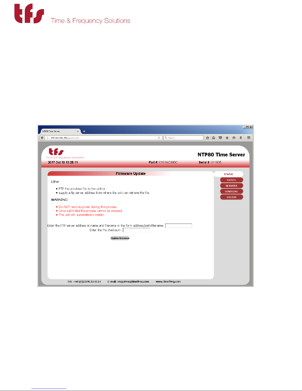
Enter http://<IP.ADDRESS>/update.html into a browser.
There are two ways to update the firmware:
1/ if an FTP server is available then load the .x file onto the FTP server and specify
the full path name in the FTP server address field box as <ftp
server>/path/update-file-name.x. In the checksum field enter the checksum
provided in the .ck file.
MANUAL P/N 900000165 REV H
Page 48
48
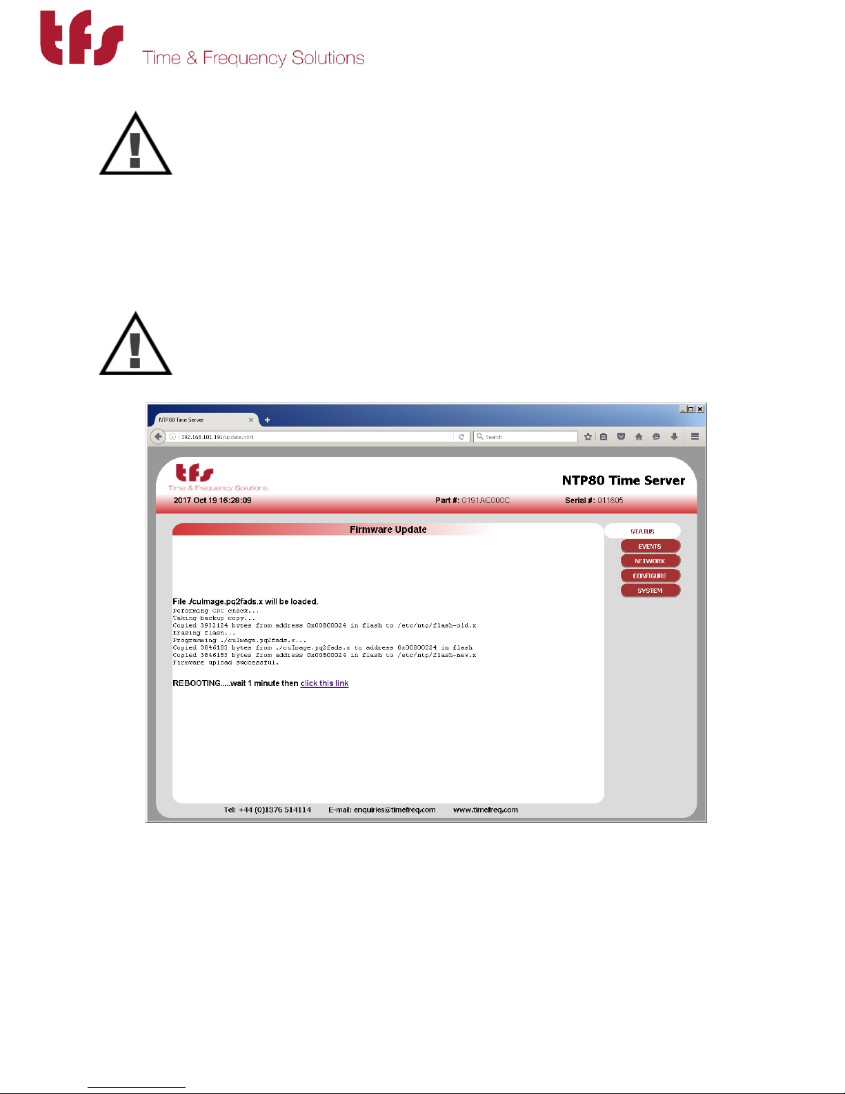
Ensure that the power supply will not be interrupted and press submit.
2/ The firmware update can be transferred to the NTP80 with an FTP client, such as
FileZilla. In the client enter the IP address of the NTP80, there is no username or
password. Then upload the .x file. Leave the FTP server address field blank and
enter the checksum provided in the .ck file in the checksum field.
Ensure that the power supply will not be interrupted and press submit.
Wait 1 minute for reboot and press the link to take you back to the status page.
If there are any problems with the uploaded file or in the process of writing the new file to flash
memory these will be detected and the original firmware restored.
MANUAL P/N 900000165 REV H
Page 49

49
13 Appendix B: MIB File
The MIB files for the NTP80plus and NTP80plus are listed here. There are three MIB files that define the NTP80plus
enterprise MIB:
13.1 TFS-NTPCOMMON-MIB.mib
--*********************************************************************--
-- TFS Enterprise MIB --
-- --
-- for s/w 0123NT-X --
-- --
-- v7.00 Rationalisation of TFS mibs for all products. --
-- Initial specific common MIB for NTP80plus. -- --
--
--*********************************************************************--
TFS DEFINITIONS ::= BEGIN
IMPORTS
enterprises
FROM RFC1155-SMI
OBJECT-TYPE
FROM RFC-1212
TRAP-TYPE
FROM RFC-1215;
tfs OBJECT IDENTIFIER ::= {enterprises 10784}
common OBJECT IDENTIFIER ::= {tfs 3}
servertype OBJECT-TYPE
SYNTAX INTEGER
{ ntp8 (1),
tfdNTP (2),
tfdATM (3),
tfdSCCAM (4),
m21xETH (5),
m21xATM (6),
ntpDISP (7),
NTP80plus (8),
ptp80 (9),
ptp8 (10)
}
ACCESS read-only
STATUS mandatory
DESCRIPTION "Indicates type of unit and hence its functionality"
::= {common 1}
modelNo OBJECT-TYPE
SYNTAX OCTET STRING (SIZE(0..16))
ACCESS read-only
STATUS mandatory
DESCRIPTION "Model number"
::= {common 2}
serialnumber OBJECT-TYPE
SYNTAX OCTET STRING (SIZE(0..5))
ACCESS read-only
STATUS mandatory
DESCRIPTION "Internal serial number of unit"
::= {common 3}
MANUAL P/N 900000165 REV H
Page 50

50
codenumber OBJECT-TYPE
SYNTAX OCTET STRING (SIZE(0..14))
ACCESS read-only
STATUS mandatory
DESCRIPTION "Firmware part number"
::= {common 4}
codeversion OBJECT-TYPE
SYNTAX OCTET STRING (SIZE(0..8))
ACCESS read-only
STATUS mandatory
DESCRIPTION "Firmware version number"
::= {common 5}
systemstatus OBJECT IDENTIFIER ::= {tfs 4}
lastevent OBJECT-TYPE
SYNTAX INTEGER
ACCESS read-only
STATUS mandatory
DESCRIPTION "Last event ID"
::= {systemstatus 2}
syslogTable OBJECT-TYPE
SYNTAX SEQUENCE OF SyslogEntry
ACCESS not-accessible
STATUS mandatory
DESCRIPTION "System log table"
::= {systemstatus 1}
syslogEntry OBJECT-TYPE
SYNTAX SyslogEntry
ACCESS not-accessible
STATUS mandatory
DESCRIPTION "System log record"
INDEX {eventid}
::= {syslogTable 1}
SyslogEntry ::= SEQUENCE { timestamp INTEGER,
resolver INTEGER,
eventid INTEGER,
severity INTEGER,
module OCTET STRING,
function OCTET STRING,
description OCTET STRING
}
timestamp OBJECT-TYPE
SYNTAX INTEGER
ACCESS read-only
STATUS mandatory
DESCRIPTION "time as number of secs since 1 January 1970"
::={syslogEntry 1}
resolver OBJECT-TYPE
SYNTAX INTEGER
ACCESS read-only
STATUS mandatory
DESCRIPTION "fractions of seconds as a count of 15.25ns pulses"
::={syslogEntry 2}
eventid OBJECT-TYPE
SYNTAX INTEGER (1..2147483647)
ACCESS read-only
STATUS mandatory
DESCRIPTION "Event log index"
::={syslogEntry 3}
severity OBJECT-TYPE
MANUAL P/N 900000165 REV H
Page 51

51
SYNTAX INTEGER
{ sysOK (0),
sysFATAL (1),
sysWARN (2),
sysNET (3),
sysINF (4),
sysERR (5)
}
ACCESS read-only
STATUS mandatory
DESCRIPTION "Event type"
::={syslogEntry 4}
module OBJECT-TYPE
SYNTAX OCTET STRING
ACCESS read-only
STATUS mandatory
DESCRIPTION "Originating module"
::={syslogEntry 5}
function OBJECT-TYPE
SYNTAX OCTET STRING
ACCESS read-only
STATUS mandatory
DESCRIPTION "function within module"
::={syslogEntry 6}
description OBJECT-TYPE
SYNTAX OCTET STRING
ACCESS read-only
STATUS mandatory
DESCRIPTION "Description of event"
::={syslogEntry 7}
linuxlogTable OBJECT-TYPE
SYNTAX SEQUENCE OF LinuxlogEntry
ACCESS not-accessible
STATUS mandatory
DESCRIPTION "System log table"
::= {systemstatus 4}
linuxlogEntry OBJECT-TYPE
SYNTAX LinuxlogEntry
ACCESS not-accessible
STATUS mandatory
DESCRIPTION "System log record"
INDEX {line}
::= {linuxlogTable 1}
LinuxlogEntry ::= SEQUENCE { line INTEGER,
timestr OCTET STRING,
process OCTET STRING,
message OCTET STRING
}
line OBJECT-TYPE
SYNTAX INTEGER (1..2147483647)
ACCESS read-only
STATUS mandatory
DESCRIPTION "Event log index"
::={linuxlogEntry 1}
timestr OBJECT-TYPE
SYNTAX OCTET STRING
ACCESS read-only
STATUS mandatory
DESCRIPTION "Event type"
::={linuxlogEntry 2}
process OBJECT-TYPE
MANUAL P/N 900000165 REV H
Page 52

52
SYNTAX OCTET STRING
ACCESS read-only
STATUS mandatory
DESCRIPTION "Event type"
::={linuxlogEntry 3}
message OBJECT-TYPE
SYNTAX OCTET STRING
ACCESS read-only
STATUS mandatory
DESCRIPTION "Description of event"
::={linuxlogEntry 4}
modules OBJECT IDENTIFIER ::= {tfs 8}
eventTrap TRAP-TYPE
ENTERPRISE tfs
VARIABLES { timestamp,
resolver,
eventid,
severity,
module,
function,
description
}
DESCRIPTION "System log event trap" ::= 8
END
MANUAL P/N 900000165 REV H
Page 53

53
13.2 TFS-GPS-MIB.mib
--*********************************************************************--
-- TFS Enterprise MIB --
-- --
-- for s/w 0123NT-X --
-- --
-- v7.00 Rationalisation of TFS mibs for all products. --
-- Initial GPS MIB for NTP80plus. --
-- --
--*********************************************************************--
TFS-GPS DEFINITIONS ::= BEGIN
IMPORTS
enterprises
FROM RFC1155-SMI
OBJECT-TYPE
FROM RFC-1212
TRAP-TYPE
FROM RFC-1215
tfs, modules
FROM TFS;
gps OBJECT IDENTIFIER ::= {modules 1}
gpslastupdate OBJECT-TYPE
SYNTAX INTEGER
ACCESS read-only
STATUS mandatory
DESCRIPTION "Time of Last update"
::= {gps 1}
visible OBJECT-TYPE
SYNTAX INTEGER
ACCESS read-only
STATUS mandatory
DESCRIPTION "Visible Satellites"
::= {gps 2}
tracked OBJECT-TYPE
SYNTAX INTEGER
ACCESS read-only
STATUS mandatory
DESCRIPTION "Tracked Satellites"
::= {gps 3}
status OBJECT-TYPE
SYNTAX OCTET STRING
ACCESS read-only
STATUS mandatory
DESCRIPTION "Text status."
::= {gps 4}
status1 OBJECT-TYPE
SYNTAX OCTET STRING
ACCESS read-only
STATUS mandatory
DESCRIPTION "GPS status flags 1"
::= {gps 5}
status2 OBJECT-TYPE
SYNTAX OCTET STRING
ACCESS read-only
STATUS mandatory
DESCRIPTION "GPS status flags 2"
::= {gps 6}
MANUAL P/N 900000165 REV H
Page 54

54
latitude OBJECT-TYPE
SYNTAX OCTET STRING
ACCESS read-only
STATUS mandatory
DESCRIPTION "latitude degrees N"
::= {gps 7}
longitude OBJECT-TYPE
SYNTAX OCTET STRING
ACCESS read-only
STATUS mandatory
DESCRIPTION "longitude degrees E"
::= {gps 8}
height OBJECT-TYPE
SYNTAX OCTET STRING
ACCESS read-only
STATUS mandatory
DESCRIPTION "m above ellipsoid"
::= {gps 9}
lastlock OBJECT-TYPE
SYNTAX OCTET STRING
ACCESS read-only
STATUS mandatory
DESCRIPTION "Last lock time s since 1/1/1970"
::= {gps 10}
statusAB OBJECT-TYPE
SYNTAX INTEGER
ACCESS read-only
STATUS mandatory
DESCRIPTION "Integer value of status1"
::= {gps 11}
statusAC OBJECT-TYPE
SYNTAX INTEGER
ACCESS read-only
STATUS mandatory
DESCRIPTION "Integer value of status2"
::= {gps 12}
gpsmode OBJECT-TYPE
SYNTAX INTEGER
ACCESS read-only
STATUS mandatory
DESCRIPTION "Bit flags 2 - GPS not found,
1 - Not loaded last frame
0 - Not loaded since reset
so zero is normal operation. "
::= {gps 13}
END
MANUAL P/N 900000165 REV H
Page 55

55
13.3 TFS-NTP-MIB.mib
--*********************************************************************--
-- TFS Enterprise MIB --
-- --
-- for s/w 0123NT-X --
-- --
-- v7.00 Rationalisation of TFS mibs for all products. --
-- Initial specific NTP MIB for NTP80plus. --
-- --
--*********************************************************************--
TFS-NTP DEFINITIONS ::= BEGIN
IMPORTS
enterprises
FROM RFC1155-SMI
OBJECT-TYPE
FROM RFC-1212
TRAP-TYPE
FROM RFC-1215
tfs, modules
FROM TFS;
ntp OBJECT IDENTIFIER ::= {modules 2}
ntplastupdate OBJECT-TYPE
SYNTAX OCTET STRING
ACCESS read-only
STATUS mandatory
DESCRIPTION "Time of Last update"
::= {ntp 1}
status OBJECT-TYPE
SYNTAX OCTET STRING
ACCESS read-only
STATUS mandatory
DESCRIPTION "Text status."
::= {ntp 2}
syncsource OBJECT-TYPE
SYNTAX OCTET STRING
ACCESS read-only
STATUS mandatory
DESCRIPTION "NTP peer or GPS."
::= {ntp 3}
stratum OBJECT-TYPE
SYNTAX INTEGER
ACCESS read-only
STATUS mandatory
DESCRIPTION "unit stratum, -1 means not set."
::= {ntp 4}
clkOffset OBJECT-TYPE
SYNTAX OCTET STRING
ACCESS read-only
STATUS mandatory
DESCRIPTION "Clock offset s"
::= {ntp 6}
clkJitter OBJECT-TYPE
SYNTAX OCTET STRING
ACCESS read-only
STATUS mandatory
DESCRIPTION "clock jitter s"
::= {ntp 7}
clkFreq OBJECT-TYPE
MANUAL P/N 900000165 REV H
Page 56

56
SYNTAX OCTET STRING
ACCESS read-only
STATUS mandatory
DESCRIPTION "Frequency error ppm"
::= {ntp 8}
clkStability OBJECT-TYPE
SYNTAX OCTET STRING
ACCESS read-only
STATUS mandatory
DESCRIPTION "Clock stability ppm"
::= {ntp 9}
ntpmode OBJECT-TYPE
SYNTAX INTEGER
ACCESS read-only
STATUS mandatory
DESCRIPTION "Bit flags set means
2 - NTP peer to peer not locked,
1 - GPS source not locked,
0 - Time not loaded
so for GPS, 4 is normal operation & for NTP only, 2 is normal."
::= {ntp 10}
END
bit 3 - NTP no peers,
MANUAL P/N 900000165 REV H
Page 57

57
14 Support Information
If the unit is still exhibiting problems not covered by the troubleshooting guide, contact us for
technical support at
Time & Frequency Solutions Ltd
25 Eastways
Witham
Essex
CM8 3AL
United Kingdom
Tel +44 (0) 1376 514114
Fax +44 (0) 1376 516116
Email [email protected] or [email protected]
Time & Frequency Solutions is a wholly owned subsidiary of Brandywine Communications and
so technical support is also available from [email protected] or call us at +1
(714) 755-1050.
If it becomes necessary to return the unit to the factory for repairs, call us at 714-755-1050
extension 113 to arrange an RMA.
MANUAL P/N 900000165 REV H
 Loading...