

5. Applications 6. Specification
1. Connect the ‘BOOST’ and the
‘TIMED ON’ as required in Fig. 6,7 & 8.
2. Assemble the timer to the back plate by
aligning the location pins on the top of the
backplate with the cut outs provided on
the clock body. Lock in position using a
fixing screw.
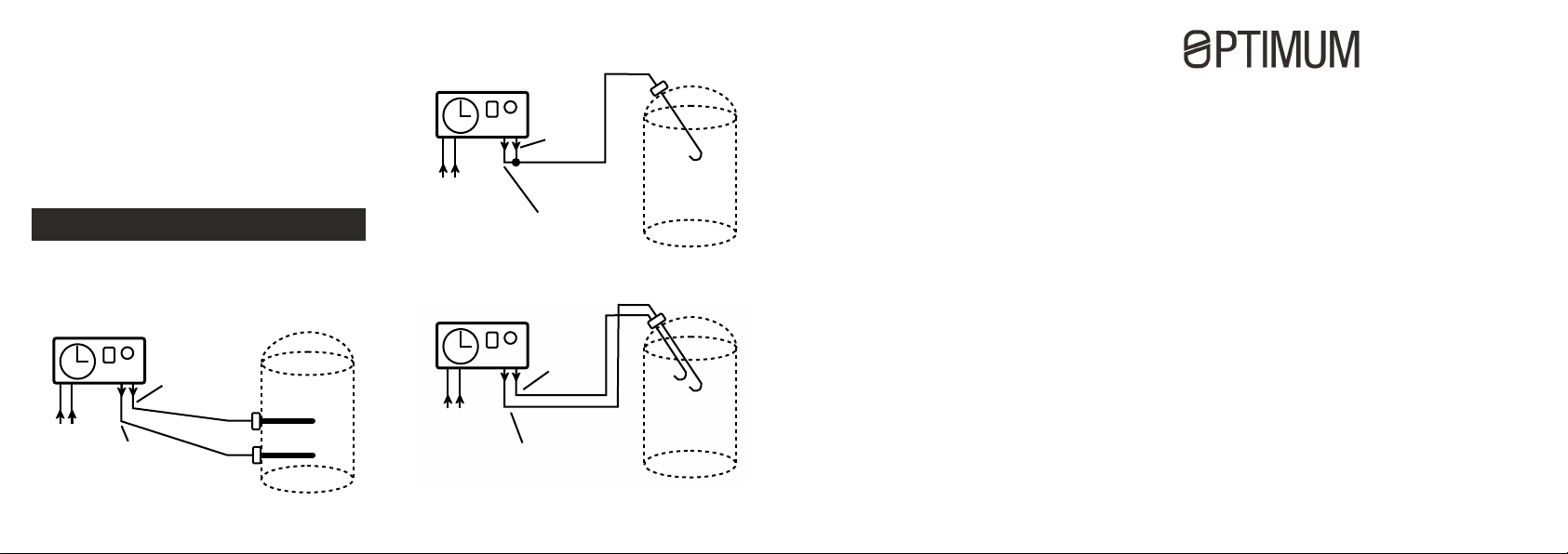
APPLICATIONS
This timer controls the use of cheap rate
electricity during the night to heat the
water in your tank for the following
applications:
BOOST LOAD
MAINS
SUPPLY
Fig. 6
Two separate immersion heaters.
TIME ON
LOAD
BOOST LOAD
MAINS
SUPPLY
TIME ON LOAD
Fig. 7
Single immersion heater.
BOOST LOAD
MAINS
SUPPLY
TIME ON LOAD
Fig. 8
Dual immersion heaters.
Voltage: 220-240V AC 50Hz
Temperature rating: -10 C to 55 C
Max Current: 16A resistive / 2A inductive
Boost: adjustable between 15 and 120 mins
Fitting: Surface mounting
Dims (mm): 86H x 155W x 55D
Protection Category: IP20
Complies with European Norm
EN 60730-1: 2011
Automatic Electrical Controls for
Household and similar use,
and European Directives:
LVD; EMC; RoHS
www.tfc-group.co.uk
TFC Group LLP Tonbridge TN9 1TB
ECONOMY 7
TIMER
For general purpose use
Installer instructions
OP-ECOSAVE Economy 7 / Multi Tariff Timer
Min switching 15 Minutes
1. Notice
2. Installation
3. Surface / Box fitting
4. Wiring connections
5. Applications
6. Specification
OP-ECOSAVE Installer Instructions

1. Notice 2. Installation 3. Surface / Box fitting 4. Wiring Connections
Please read the instructions fully before
attempting installation.
IMPORTANT
This unit should be installed to current
IEE wiring regulations. If in doubt consult
a qualified electrician.
• Timer must not be mounted on a
flammable surface.
• Ensure that the timer does not come
into contact with any combustible
materials such as towels or bedding.
• Ensure at least a 300 mm air space is
allowed around the timer.
INSTALLATION
THIS TIMER SHOULD NOT BE
FITTED ONTO A CONDUCTIVE
SURFACE (i.e. METAL)
Before you begin the installation.
1. Disconnect the mains supply
2. The Dual Tariff Boost Timer is
suitable for fixed wiring only.
3. The following cable cross sections
are possible:
Fig. 1
3 x 2.5 mm
(2X) output
2
Fig. 2
3 x 4mm
(2X) output
2
1. Select the single or twin box fixing
points on the plate.
2. If the timer is to be surface mounted:
select the single or twin fixing points
on the back plate.
3. Wire entry from rear, both sides
possible.
Note:
If connecting to terminals with stranded flex,
the supplied crimp ferrules MUST be used.
Fig. 3
box
Fig. 4
box
1. Connect main cable as shown in
Fig. 5 below.
2. Select desired flexible cable outlet
to immersion heaters and using
pliers remove the selected slot.
3. Clamp cables using attached cable
clamp.
NOTE:
Use the terminals 1 to 5 as identified.
BOOST
ON/OFF
SWITCH
Fig. 5
1
2 3
LNNLL
MAINS
SUPPLY
5
4
BOOST LOAD
TIME ON LOAD
NEUTRAL
OP-ECOSAVE Installer Instructions
 Loading...