


WEATHER STATION
Instruction Manual
Thank you for choosing this wireless weather station from
TFA.
BEFORE YOU USE IT
Please be sure to read the instruction manual
carefully.
This information will help you to familiarise yourself with
your new device, learn all of its functions and parts, find
out important details about its first use and how to operate
it, and get advice in the event of faults.
Following the instruction manual for use will prevent
damage to the device and loss of your statutory rights
arising from defects due to incorrect use.
We shall not be liable for any damage occurring as a
result of not following these instructions.
Please take particular note of the safety advice!
Please look after this manual for future reference.
SCOPE OF SUPPLY:
•
Weather station (basic unit)
•
Outdoor transmitter
•
Instruction manual
FIELD OF OPERATION AND ALL OF THE
BENEFITS OF YOUR NEW WEATHER STATION AT
A GLANCE
•
DCF Radio controlled time with manual setting
option
•
Time reception ON/OFF (user selectable)
•
Time zone option ±12 hours
•
Calendar display (year only in setting mode)
•
Display 8 moon phases
•
Weather forecasting with weather tendency i ndicator
•
Indoor and outdoor temperature display with
MIN/MAX records
•
Temperature display in ºC
•
Indoor and outdoor humidity display
•
Humidity data display as RH%
•
Low battery indicator
•
Table standing or wall mounting
Cat. No. 35.1111.IT
20

FOR YOUR SAFETY:
•
The product is exclusively intended for the fi eld of
application described above. The product should
only be used as described within these instructions.
•
Unauthorised repairs, modifications or changes to
the product are prohibited.
•
The product is not to be used for medical purpose or
for public information, but is intended solely for
home use.
Caution!
Risk of injury:
•
•
•
! Important information on product safety!
•
•
Keep this instrument and the batteries out of reach
of children.
Batteries must not be thrown into the fire, shortcircuited, taken apart or recharged. Risk of
explosion!
Batteries contain harmful acids. Low batteri es
should be changed as soon as possible to preve nt
damage caused by a leaking battery. Never use a
combination of old and new batteries together or
batteries of different types. Wear chemical-resistant
protective gloves and glasses when handling leaked
batteries.
Do not expose the instrument to extreme
temperatures, vibration or shock.
The outdoor transmitter is protected against splash
water, but is not watertight. Choose a shady a nd dry
position for the transmitter.
21
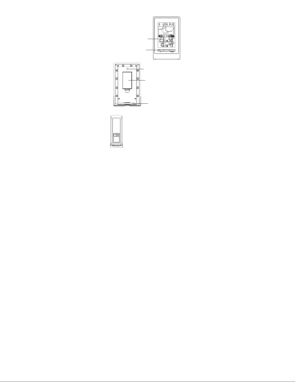
LCD
ELEMENTS
The Weather Station
Display
Function keys
Thermo-Hygro Transmitter
•
•
•
•
Hanging hole
Battery
compartment
Stand
Remote transmission of outdoor
temperature and humidity to weather
station by 868MHz
Alternately display the outdoor
temperature and humidity readings
on LCD
Wall mounting case
Mounting at a sheltered place. Avoid
direct rain and sunshine
TO INSTALL AND REPLACE BATTERIES IN THE
THERMO-HYGRO TRANSMITTER
The outdoor thermo-hygro transmitter uses 2 x AAA, IEC
LR3, 1.5V batteries. To install and replace the batteries,
please follow the steps below:
22
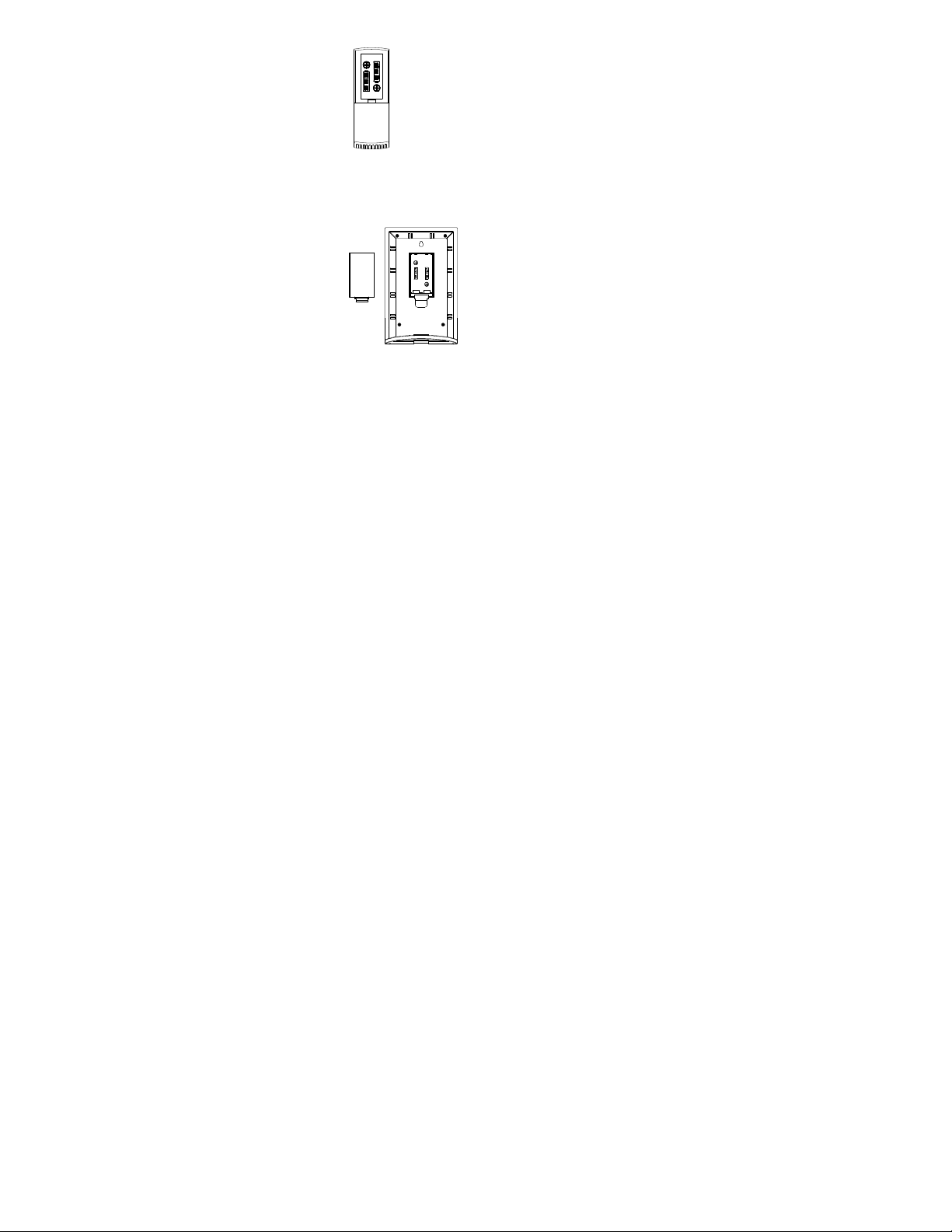
1. Remove the battery cover by pushing
the battery cover upwards with your
thumb.
2. Insert the batteries, observing the
correct polarity (see battery
compartment marking).
3.
Replace the battery cover on the unit.
TO INSTALL AND REPLACE BATTERIES IN THE
WEATHER STATION
The weather station uses 2 x AA, IEC LR6, 1.5V batteries.
To install and replace the batteries, please foll ow the steps
below:
Battery replacement
•
Replace the batteries when the battery symbol of
the weather station appears on the upper display.
•
When the batteries of the transmitter are used up,
the low battery icon appears next to the outdoor
temperature display.
Note:
In the event of changing batteries in any of the units, all
units need to be reset by following the setti ng up
procedures. This is due to a random securi ty code
assigned by the transmitter at start-up. This code must be
received and stored by the weather station i n the first 3
minutes of power being supplied to the transmitter.
1. Insert finger or other
solid object in the
space at the bottom
center of the battery
compartment and lift up
to remove the cover.
2. Insert batteries
observing the correct
polarity (see marking).
3. Replace compartment
cover.
23

SETTING UP
1. First, insert the batteries in the transmitter (see “To
install and replace batteries in the thermo-hygro
transmitter” above).
2. Within 2 minutes of powering up the transmi tter,
insert the batteries in the weather station (see “To
install and replace batteries in the weather
station” above). Once the batteries are in pl ace, all
segments of the LCD will light up briefly. Following
the indoor temperature/humidity and the time as
00:00 will be displayed. If these information are not
displayed on the LCD after 60 seconds, remove the
batteries and wait for at least 60 seconds before
reinserting them. Once the indoor data is di splayed
user may proceed to the next step.
3. After the batteries are inserted, the weather station
will start receiving data signal from the transmitter.
The outdoor temperature and humidity data sho uld
then be displayed on the weather station. If this
does not happen after 2 minutes, the batteri es will
need to be removed from both units and reset from
step 1.
4. In order to ensure sufficient 868 MHz transmission
however, the distance between the weather stati on
and the transmitter should not be more than 100
meters (see notes on “Positioning” and “868 MHz
Reception”).
Note:
In the event of changing batteries of the units,
ensure the batteries do not spring free from the
contacts. Always wait at least 1 minute after
removing the batteries before reinserting, otherwise
start up and transmission problems may occur.
5. Once the outdoor data reception test period i s
completed, the DCF tower icon in the clock display
will start flashing in the upper left corner. This
indicates that the clock has detected that there is a
radio signal present and is trying to receive i t. When
the time code is received, the DCF tower becomes
permanently lit and the time will be displayed.
24

DCF RADIO CONTROLLED TIME
The time base for the radio controlled time i s a Cesium
Atomic Clock operated by the Physikalisch Technische
Bundesanstalt Braunschweig which has a ti me deviation of
less than one second in one million years. The time is
coded and transmitted from Mainflingen near Frankfurt via
frequency signal DCF-77 (77.5 kHz) and has a
transmitting range of approximately 1,500 km. Your radiocontrolled weather station receives this signal and
converts it to show the precise time in summer or
wintertime.
The quality of the reception depends greatly on the
geographic location. In normal cases, there sho uld be no
reception problems within a 1,500 km radius of Frankfurt.
DCF reception is done twice daily at 02:00 and 03:00 am.
If the reception is not successful at 03:00 am, then the
next reception takes place the next hour and so o n until
06:00am, or until the reception is successful. If the
reception is not successful at 06:00 am, then the next
attempt will take place the next day at 02:00 am.
If the tower icon flashes, but does not set the time or the
DCF tower does not appear at all, then please take note of
the following:
•
Recommended distance to any interfering sources
like computer monitors or TV sets is a minimum of
1.5 - 2 meters.
•
Within ferro-concrete rooms (basements,
superstructures), the received signal is naturally
weakened. In extreme cases, please place the unit
close to a window and/ or point its front or back
towards the Frankfurt transmitter.
•
During nighttime, the atmospheric disturbances are
usually less severe and reception is possibl e in most
cases. A single daily reception is adequate to keep
the accuracy deviation below 1 second.
25

FUNCTION KEYS:
Weather Station:
The weather station has 3 easy to use functi on keys:
SET key
SET key
•
Press and hold the key to enter manual setti ng
modes: time zone, manual time setting, cal endar,
time reception ON/OFF
+ key
•
Increase, change, toggle all values in manual set
mode
MIN/MAX key
•
Press shortly to toggle between indoor and outdoor
MAX/MIN temperature and current temperature
+ key
MIN/MAX key
26

LCD SCREEN
Moon
phase
Time
reception
icon (for
Indoor
temperature
Weather
Outdoor
rature
in ºC
The LCD screen is split into 5 sections displ aying the
information for time/calendar, weather forecast, moon
phase, indoor data, and outdoor data.
Low battery indicator
(weather station)
Time
DCF time)
forecast icon
Calendar
Weather
tendency
indicator
icon
in ºC
tempe
* When the signal is successfully received by the weather
station, the outdoor transmission icon will be switched on.
(If not successful, the icon will not be shown on LCD). The
user can then easily see whether the last reception was
successful (icon on) or not (icon off).
MANUAL SETTINGS:
The following manual settings can be changed by pressing
and holding the SET key:
•
•
•
•
Outdoor data signal
reception indicator*
Time zone setting
Manual time setting
Calendar setting
Time reception ON/OFF setting
Outdoor relative
humidity in RH%
Indoor
relative
humidity
in RH%
Low battery
indicator
(transmitter)
27

TIME ZONE SETTING:
The time zone default of the weather station is “0”. To set
a different time zone:
1. The current time zone value starts flashing.
2. Use the + key to set the time zone. The range runs
from 0 to -12 and then runs from +12 back to 0 in
consecutive 1-hour intervals.
3. Confirm with the SET key and enter the Manual
Time Setting.
MANUAL TIME SETTING:
In case the weather station cannot detect the DCF-signal
(for example due to disturbances, transmitti ng distance,
etc.), the time can be manually set. The clock will then
work as a normal quartz clock.
Flashing
1. The hour digit will start flashing.
2. Use the + key to set the hour.
3. Press again the SET key to set the minutes. The
4. Use the + key to set the minutes.
5.
Note:
The unit will still try and receive the signal despite it being
manually set. When it does receive the signal, it will
change the manually set time into the recei ved time.
During reception attempts the DCF tower icon will flash. If
reception has been unsuccessful, then the DCF tower icon
will not appear but reception will still be attempted the
following day.
Hour flashing
minute digits start flashing.
Confirm with the SET key and enter the Calendar
setting.
Minutes flashing
28

CALENDAR SETTING:
Year
The date default of the weather station is 1. 1. 2011. Once
the radio-controlled time signals are received, the date is
automatically updated. However, if the signals are not
received, the date can also be set manually.
1. The year starts flashing.
2. Use the + key to set the year (between year 2011-
2039).
3. Press the SET key again to confirm and to enter the
month setting. The month starts flashing.
4. Use the + key to set the month.
5. Press the SET key again to confirm and to enter the
date setting mode. The date starts flashing.
6. Use the + key to set the date.
7.
Confirm all calendar settings with the SET key and
enter the Time reception ON/OFF setting.
TIME RECEPTION ON/OFF SETTING:
Date and month
In areas where reception of the DCF time is not possible,
the DCF time reception function can be turned OFF. The
clock will then work as a normal quartz clock. (Default
setting is ON).
1. The digit “ON” will start flashing on the LCD.
2. Use the + key to turn OFF the time reception
function.
3. Confirm with the SET key and exit the manual
setting.
Flashing
29

Note:
If the Time Reception function is turned OFF manually,
the clock will not attempt any reception of the DCF
time as long as the Time Reception OFF function is
activated.
The time reception icon “ “ will not be displayed on
the LCD.
TO EXIT THE MANUAL SETTING MODE
To exit the manual setting mode anytime during the
manual setting, wait for automatic timeout. The mode will
return to normal time display.
MOON PHASES SYMBOL
The moon icon of the weather station will also display all 8
moon phases throughout the year according to t he set
calendar. A bar segment above the moon phase will
indicate the current moon phase.
First
Waxing
Quarter
Crescent
WEATHER FORECAST AND WEATHER
TENDENCY:
WEATHER FORECASTING ICONS:
The weather icons in the second section of LCD can be
displayed in any of the following combinations:
Sunny Cloudy with sunny intervals Rainy
For every sudden or significant change in the air pressure,
the weather icons will update accordingly to represent the
change in weather. If the icons do not change, t hen it
means either the air pressure has not changed or the
change has been too slow for the weather stati on to
register. However, if the icon displayed is a sun or raining
cloud, there will be no change of icon if the weat her gets
Bar segment (moon phase indicator)
Waxing
Gibbous
Full
Moon
Waning
Gibbous
Last
Quarter
Waning
Crescent
New
Moon
30

any better (with sunny icon) or worse (with rainy icon)
since the icons are already at their extremes.
The icons displayed forecasts the weather i n terms of
getting better or worse and not necessaril y sunny or rainy
as each icon indicates. For example, if the current weather
is cloudy and the rainy icon is displayed, i t does not mean
that the product is faulty because it is not rai ning. It simply
means that the air pressure has dropped and the weather
is expected to get worse but not necessaril y rainy.
Note:
After setting up, readings for weather forecasts should be
disregarded for the next 12-24 hours. This will allow
sufficient time for the weather station to coll ect air
pressure data at a constant altitude and therefore result in
a more accurate forecast.
Common to weather forecasting, absolute accuracy
cannot be guaranteed. The weather forecasti ng feature is
estimated to have an accuracy level of about 75% due to
the varying areas the weather station has bee n designed
for use. In areas that experience sudden changes in
weather (for example from sunny to rain), the weather
station will be more accurate compared to use i n areas
where the weather is stagnant most of the ti me (for
example mostly sunny).
If the weather station is moved to another location
significantly higher or lower than its initial standing point
(for example from the ground floor to the upper floors of a
house), discard the weather forecast for the next 12-24
hours. By doing this, the weather station will not mistake
the new location as being a possible change i n air
pressure when really it is due to the slight change of
altitude.
WEATHER TENDENCY INDICATOR
The weather tendency indicators (located on the left and
right sides of the weather icons) are working together with
the weather icons. When the indicator points upwards, it
means that the air pressure is increasing and the weather
is expected to improve, but when indicator poi nts
downwards, the air pressure is dropping and the weather
is expected to become worse.
Taking this into account, one can see how the weather has
changed and is expected to change. For example, if the
31

Indoor
temperature
indicator is pointing downwards together wi th cloud and
Outdoor
temperature
in ºC
sun icons, then the last noticeable change in the weather
was when it was sunny (the sun icon only). Therefore, the
next change in the weather will be cloud wi th rain icons
since the indicator is pointing downwards.
Note:
Once the weather tendency indicator has regi stered a
change in air pressure, it will remain permanently
visualized on the LCD.
INDOOR TEMPERATURE/HUMIDITY DATA
The indoor temperature and humidity data are
automatically updated and displayed on the fourt h section
of the LCD.
in ºC
OUTDOOR TEMPERATURE/HUMIDITY DATA
The last LCD section shows the outdoor temperature and
humidity, and the reception indicator.
TOGGLING AND RESETTING THE MIN/MAX DATA
TO VIEW THE MIN/MAX DATA
Press the MIN/MAX key several times to view the
MIN/MAX indoor temperature, and MIN/MAX outdoor
temperature sequentially.
TO RESET THE MIN/MAX DATA
Press and hold MIN/MAX key for 3 seconds to reset all
the indoor and outdoor temperature to current
temperatures.
ABOUT THE THERMO-HYGRO TRANSMITTER
The range of the thermo-hygro transmitter may be affected
by the temperature. At cold temperatures the transmitting
Outdoor data signal
reception indicator
Indoor
relative
humidity
in RH%
Low battery
indicator
(transmitter)
Outdoor relative
humidity in RH%
32

distance may be decreased. Please bear this i n mind
when positioning the transmitters. Also the batteries may
be reduced in power for the thermo-hygro transmitter.
CHECKING FOR 868MHz RECEP TION
If the outdoor temperature and humidity data are not being
received within three minutes after setting up (or outdoor
display always show “- -.-” in the outdoor section of the
weather station during normal operation), pl ease check the
following points:
1. The distance of the weather station or transmitters
should be at least 2 meters away from any
interfering sources such as computer monitors or TV
sets.
2. Avoid placing the transmitters onto or in the
immediate proximity of metal window frames.
3. Using other electrical products such as headp hones
or speakers operating on the 868MHz-signal
frequency may prevent correct signal transmission
or reception. Neighbors using electrical devi ces
operating on the 868MHz-signal frequency can also
cause interference.
Note:
When the 868MHz signal is received correctly, do not reopen the battery cover of either the transmi tter or weather
station, as the batteries may spring free from the contacts
and force a false reset. Should this happen accide ntally
then reset all units (see “Setting up” above) otherwise
transmission problems may occur.
The transmission range is around 100 meters from the
thermo-hygro transmitter to the weather station (in open
space). However, this depends on the surroundi ng
environment and interference levels. If no reception is
possible despite the observation of these factors, all
system units have to be reset (see “Setting up” above).
POSITIONING THE WEATHER STATION
The weather station provides the option of tabl e standing
or wall mounting the unit. Before wall mounting, please
check that the outdoor data can be received from the
desired locations.
33

To wall mount:
1. Fix a screw (not supplied) into the
desired wall, leaving the head
extended out by about 5mm.
2. Place the weather station onto the
screw, using the hanging hole on the
backside. Gently pull the weather
station down to lock the screw into
place.
Free standing:
With the detachable stand, the weather
station can be placed onto any flat surface.
POSITIONING THE THERMO-HYGRO
TRANSMITTER
and humidity readings are receivable. In event that the
signal is not received, relocate the thermo-hygro
transmitter or the weather station slightly as this may help
the signal reception.
Mounting at a sheltered place. Avoid direct
rain and sunshine.
The thermo-hygro transmitter can be placed
onto any flat surface or wall mount using the
bracket which doubles as a stand or wall
mount base.
To wall mount:
1. Secure the bracket onto a desired wall
using the screws and plastic anchors.
2. Clip the transmitter onto the bracket.
Note:
Before permanently fixing the thermo-hygro to
the wall base, place all units in the desired
locations to check that the outdoor temperature
34

CARE AND MAINTENANCE
•
Clean the instrument and the transmitter wi th a soft
damp cloth. Do not use solvents or scouring agents.
Protect from moisture.
•
Remove the batteries if you do not use the prod uct
for a lengthy period.
TROUBLESHOOTING
Problems Solution
No indication on
the weather
station
No transmitter
reception
Display "---"
No DCF
reception
Incorrect display • Change batteries
WASTE DISPOSAL
This product has been manufactured using hig h-grade
materials and components which can be recycled and
reused.
Never throw flat batteries and
rechargeable batteries in household
waste.
As a consumer, you are legally required to
take them to your retail store or to
•
Ensure batteries polarity are
correct
•
Change batteries
•
Check batteries of external
transmitter (do not use
rechargeable batteries!)
•
Restart the transmitter and
weather station as per the
manual
•
Choose another place for the
transmitter and/or the weather
station
•
Reduce the distance between
the transmitter and the
weather station
•
Check if there is any source of
interference
•
Time reception setting “ON”
•
Choose another place for the
weather station
•
Manual time setting
•
Wait for attempted reception
during the night
35

appropriate collection sites according to nati onal or local
regulations in order to protect the environment.
The symbols for the heavy metals contained are:
Cd=cadmium, Hg=mercury, Pb=lead
of electrical and electronic equipment, in order to ensure
environmentally-compatible disposal.
SPECIFICATIONS:
Temperature measuring range:
Indoor : -9.9ºC to +59.9ºC with 0.1°C resolution
(“OF.L” displayed if outside this range)
Outdoor : -39.9ºC to +59.9ºC with 0.1°C resolution
(“OF.L” displayed if outside this range)
Indoor humidity range : 20% to 95% with 1% resolution
(Display “- -“ if temperature is OL.F; display “19%“ if < 20%
and “96%” if > 95%)
Outdoor humidity range : 1% to 99% with 1% resolution
(Display “- -“ if outside temperature is OF.L; display 1% if <
1% and 99% if > 99%)
Data checking intervals
Indoor temperature : every 16 seconds
Indoor humidity : every 64 seconds
Outdoor temperature and humidity: every 4 seconds
Transmission range : up to 100 meters (open space)
Power consumption (alkaline batteries recommended):
Weather station : 2 x AA, IEC LR6, 1.5V
Thermo-hygro transmitter : 2 x AAA, IEC LR3, 1.5V
Dimensions (L x W x H):
Weather station : 100 x 23.3 x 159mm
Thermo-hygro transmitter : 36 x 16 x 102.6mm
This instrument is labelled in accordance
with the EU Waste Electrical and Electronic
Equipment Directive (WEEE).
Please do not dispose of this product with
other household waste. The user is
obligated to take end-of-life devices to a
designated collection point for the disposal
36

TFA Dostmann GmbH & Co. KG, Zum Ottersberg 12, D 97877 Wertheim
No part of this manual may be reproduced wi thout written
consent of TFA Dostmann. The technical data are correct
at the time of going to print and may change wi thout prior
notice.
DECLARATION OF CONFORMITY
Herewith we declare, that this wireless transmission
device does comply with the essentials requirements of
R&TTE Directive 1999/5/EC.
A copy of the signed and dated Declaration of Co nformity
is available on request via info@tfa-dostmann.de.
www.tfa-dostmann.de
06/11
37
 Loading...