

Page 1

WIRELESS 868 MHz WEATHER STATION
Instructions manual
Thank you for choosing this instrument from TFA.
BEFORE YOU USE IT
Please be sure to read the instruction manual carefully.
This information will help you to familiarise yourself with your new device, learn all of its
functions and parts, find out important detail s about its first use and how to operate it and get
advice in the event of faults.
Following the instruction manual for use will prevent damage to the device and loss of your
statutory rights arising from defects due to i ncorrect use.
We shall not be liable for any damage occurring as a result of not following these
instructions. Likewise, we take no responsibility for any incorrect readings and for
any consequences which may result from them.
Please take particular note of the safety advice!
Please look after this manual for future reference.
Cat. No. 35.1068.IT
41
Page 2

SCOPE OF SUPPLY:
•
Weather station (basic unit)
•
Outdoor transmitter
•
Batteries (2 x AAA, 1.5 V and 2 x AA, 1.5 V)
•
Instruction manual
FIELD OF OPERATION AND ALL OF THE BENEFITS OF YOUR NEW WEATHER
STATION AT A GLANCE:
•
DCF radio controlled time with manual setting option
•
Time reception ON/OFF (user selectable)
•
12/24 hour time display
•
Time zone option (±12 hours)
•
Calendar display (day and month)
•
Weather forecasting with weather tendency i ndicator
•
Indoor comfort indicator
•
Temperature display in ºC/ºF
•
Indoor and outdoor temperature display with MIN/MAX records and time of reception
•
Indoor humidity display as RH% with MIN/MAX records
•
Weather icon sensitivity setting
•
LCD contrast selectable
42
Page 3

•
Can receive up to 3 channels
•
Low battery indicator
•
Table standing or wall mounting
FOR YOUR SAFETY:
•
The product is exclusively intended for the fi eld of application described above. The
product should only be used as described wi thin these instructions.
•
Unauthorised repairs, modifications or changes to the product are prohibited.
•
The product is not to be used for medical purpose or for public information, but is
intended solely for home use.
Caution!
Risk of injury:
•
•
•
Keep this instrument and the batteries out of reach of children.
Batteries must not be thrown into the fire, short-circuited, taken apart or recharged.
Risk of explosion!
Batteries contain harmful acids. Low batteri es should be changed as soon as possible
to prevent damage caused by a leaking battery. Never use a combination of old and
43
Page 4

new batteries together or batteries of different types. Wear chemical-resistant
LCD
Display
Function
protective gloves and glasses when handling leaked batteries.
! Important information on product safety!
•
Do not expose the instrument to extreme temperatures, vibration or shock.
•
The outdoor transmitter is protected against splash water, but is not watertight.
Choose a shady and dry position for the transmitter.
ELEMENTS
The weather station
buttons
min
44
Hanging hole
Battery compartment
Foldout
stand
Page 5
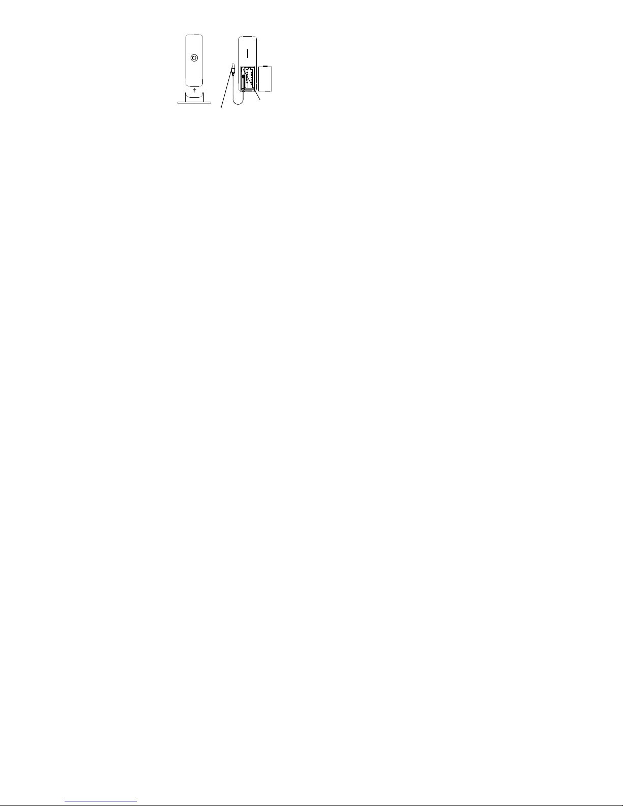
The outdoor temperature transmitter
Optional external probe
*DUAL CHANNEL TRANSMITTER
There is an internal sensor channel and an exter nal probe channel in the transmitter.
Once the temperature transmitter is successfully recognized by the weather station, channel
1 of the weather station will display the temperature data measured by internal sensor and
channel 2 will display the temperature measured by the probe.
If the measuring probe is unplugged, the "probe c hannel" on weather station (channel 2) will
show "---", yet the data from the internal sensor wi ll still be shown on channel 1 .
•
Remote transmission of outdoor temperature to
weather station by 868 MHz signals
•
Dual channel transmitter*: one internal channel
and one probe channel
•
Splash proof housing
•
Wall mounting and table stand
This socket is only for the external
probe. Do not apply power plug to it.
45
Page 6

The probe can be connected to the remote temperature transmitter any time after initi al
setup. There is no need to reset the units, should the probe be unplugged or re-plugged
again. The weather station will automaticall y detect the temperature probe data and will
display the temperature data on channel 2 after t he probe is plugged.
INSTALL AND REPLACE BATTERIES IN THE TEMPERATURE TRANSMITTER
The temperature transmitter uses 2 x AAA, IEC LR3, 1.5V batteries.
To install and replace the batteries, please foll ow the steps below:
1. Remove the battery compartment cover.
2. Insert the batteries, observing the correct pol arity (see marking).
3.
Replace the battery compartment cover.
INSTALL AND REPLACE BATTERIES IN THE WEATHER STATION
The weather station uses 2 x AA, IEC LR6, 1.5V batteries. To install and replace the
batteries, please follow the steps below:
46
Page 7

1. Insert finger or other solid object in the space at the
bottom center of the battery compartment and lift up to
remove the cover.
2. Insert batteries observing the correct polari ty (see
marking).
3. Replace compartment cover.
Battery replacement
•
Replace the batteries when the battery symbol of the weather station appears above
the indoor humidity.
•
When the batteries of the transmitter are used up, the low battery icon appears above
the outdoor temperature display.
Note:
In the event of changing batteries in any of the units, all units need to be reset by following
the setting up procedures. This is because a security code is assigned by the temperature
47
Page 8

transmitter at start-up and this code must be received and stored by the weather stati on in
the first 3 minutes of power being supplied to i t.
SETTING UP:
When one temperature transmitter is used:
1. First, insert the batteries into the temperature transmitter (see “Install and replace
batteries in the temperature transmitter” above).
2. Within 30 seconds of powering up the temperat ure transmitter, insert the batteries to
the weather station (see “Install and replace batteries in the weather station”
above). Once the batteries are in place, all segments of the LCD will light up briefly.
Then the indoor temperature and the time as 0:00 will be displayed. If they are not
shown on LCD after 60 seconds, remove the batteries and wait for at least 60
seconds before reinserting them. Once the i ndoor data is displayed, proceed to the
next step.
3. After the batteries are inserted, the weather station will start receiving data signal from
the temperature transmitter.
4. If the optional probe has been plugged to the dual channel transmitter, the outdoor
temperature should then be displayed on the weat her station on channel 1 and 2.
Also, the signal reception icon will be displayed. If this does not happen after 2
minutes, the batteries will need to be removed from both units and reset from step 1.
48
Page 9

Note:
Channel 1 will show the reading from the internal sensor of the dual channel transmitter;
channel 2 will show the reading sensed by the probe. If the probe is not plugged to the
transmitter, " - -" will be shown on channel 2.
5. In order to ensure sufficient 868 MHz transmission, the final position between the
weather station and the temperature transmi tter should not be more than 100 meters
(see notes on “Positioning” and “868 MHz reception”).
6. Once the remote temperature has been recei ved and displayed on the weather
station, the DCF time code reception is automatically started. This takes typically
between 3-5 minutes in good conditions. If the DCF time not received within 10
minutes, press the SET button to adjust the ti me manually.
When two temperature transmitters are used
1. Remove all the batteries from the weather station and temperature transmitters and
wait 60 seconds (if setting has been done wi th one temperature transmitter before).
2. Insert the batteries into the first temperature transmitter.
3. Within 30 seconds of powering up the first temperature transmitter, insert the batteries
into the weather station. Once the batteries are i n place, all segments of the LCD will
light up briefly. Then the indoor temperature and the time as 0:00 will be displayed. If
49
Page 10

they are not shown on the LCD after 60 seconds, remove the batteries and wait for at
least 60 seconds before reinserting them.
4. If the probe sensor has been installed to the first temperature transmitter, the outdoor
temperature readings from the first temperature transmitter (channel 1 and 2) should
then be displayed on the weather station. If this does not happen after 2 minutes, the
batteries will need to be removed from both units and reset from step 1.
5. Insert the batteries into the second temperature transmitter as soon as the outdoor
temperatures from the first temperature transmitter are displayed on the weather
station.
Note: Insert the batteries into the second transmitter within 20 seconds of reception of the
first temperature transmitter.
6. After the weather station has received the seco nd temperature transmitter
successfully, channel 3 will only show the data, which will be measured by the internal
sensor of the second dual channel transmitter. T he measuring data of the external
probe of the second temperature transmitter will not be shown on the display of the
weather station. The outdoor temperature readi ng from the second temperature
transmitter will be shown on the display of the weather station and the shown channel
number will be shift back to “1”, to indicate that all three channels are running
successfully. If this does not happen within 2 mi nutes, the batteries will need to be
50
Page 11

removed from all the units and reset from step 1.
6. Once the external data has been received and di splayed on the weather station, the
DCF time code reception is automatically started. This takes typically between 3-5
minutes in good conditions.
NOTE FOR RADIO-CONTROLLED TIME DCF:
The time base for the radio-controlled time i s a caesium atomic clock operated by the
Physikalisch Technische Bundesanstalt Braunschweig. It has a time deviation of less than
one second in one million years. The time i s coded and transmitted from Mainflingen near
Frankfurt via frequency signal DCF-77 (77.5 kHz) and has a transmitting range of
approximately 1,500 km. Your radio-controll ed clock receives this signal and converts it to
show the precise time. Changeover from summer time or winter time is automatic. The
quality of the reception depends mainly on the geographic location. Normally there should
be no reception problems within a 1,500 km radius around Frankfurt.
DCF reception is done twice daily at 02:00 and 03:00 am. If the reception is not successful
at 03:00 am, then the next reception takes pl ace the next hour and so on until 06:00am, or
until the reception is successful. If the recepti on is not successful at 06:00 am, then the ne xt
attempt will take place the next day at 02:00 am.
51
Page 12

If the tower icon flashes, but does not set the time or the DCF tower does not appear at all ,
IN button
then please take note of the following:
•
Recommended distance to any interfering sources like computer monitors or TV sets
is a minimum of 1.5 - 2 meters.
•
Within ferro-concrete rooms (basements, superstructures), the received signal is
naturally weakened. In extreme cases, please place the unit close to a window and/ or
point its front or back towards the Frankfurt transmitter.
•
During nighttime, the atmospheric disturbances are usually less severe and reception
is possible in most cases. A single daily reception is adequate to keep the accuracy
deviation below 1 second.
FUNCTION BUTTONS:
Weather station:
The weather station has 4 easy to use functi on buttons:
SET button
CH button
OUT button
52
Page 13

SET button
•
Press and hold the button to enter manual setting modes: LCD contrast, time zone,
time reception ON/OFF, 12/24 hour display, manual time setting, calendar,
temperature °C/°F and weather icon sensitivity setting
IN button (indoor)
•
To adjust LCD contrast, time zone, time reception ON/OFF, 12/24 hour display, hour, ,
year, day (month in 12 hour display), °C/ °F and weather forecasting icon sensitivity in
setting mode
•
Press to toggle between MAX/MIN and current indoor temperature and indoor
humidity data
•
If the button is pressed longer than 3 seconds, al l the stored minimum and maximum
values of indoor temperature and indoor humidi ty will be deleted (all data will be reset
to the actual data).
OUT button (outdoor)
•
To adjust minute and month (day in 12 hour display) in setting mode
•
Press to toggle between MAX/MIN and current outdoor temperature data
•
If the button is pressed longer than 3 seconds, al l the stored minimum and maximum
values of outdoor temperature will be deleted (all data will be reset to the actual data).
53
Page 14

CH button (channel)
Time reception icon
Indoor
temperature
in ºC/ ºF
Weather
Outdoor
temperature
in ºC/ ºF
•
Exit the manual setting mode
•
Press and switch among display of channel s (if more than 1 channel is used)
LCD SCREEN:
(for DCF time)
forecast icon
Comfort indicator icon
min
54
Time
Calendar display
Weather tendency
indicator
Low battery indicator
(weather station)
Indoor relative
humidity in RH%
Low battery indicator
(transmitter)
Outdoor data signal
reception indicator*
Channel identification
number
Page 15

* When the outdoor signal is successfully received by the weather station, this icon will be
switched on (if not successful, the icon will not be shown in LCD). So you can easil y see
whether the last reception was successful (i con on) or not (icon off).
MANUAL SETTINGS:
The following manual settings can be done i n the setting mode. Press and hold the SET
button for about 3 seconds to advance to the setti ng mode:
•
LCD contrast setting
•
Time zone setting
•
Time reception ON/OFF setting (RCC)
•
12/24 hour time format setting
•
Manual time setting
•
Calendar setting (year, month, date)
•
°C/ °F temperature unit setting
•
Weather forecasting icon sensitivity setting
55
Page 16

LCD CONTRAST SETTING
The LCD contrast can be set in 8 different l evels (0 to 7) (default LCD contrast setting i s
LCD 5).
1. Press and hold the SET button until the displ ay is flashing.
2. Use the IN button to select the desired level of contrast.
3.
Press the SET button to confirm and enter the “Time zone setting”.
TIME ZONE SETTING:
The time zone default of the weather station is “Oh”. To change to another time zone:
1. The actual value of the time zone is flashing.
2. Use the IN button to set the desired time zone. The range runs in one-hour intervals
from 0 to +12, then switch to -12 and runs back to 0.
3. Press the SET button to confirm and enter the “Time reception On/Off setting”.
flashing
56
flashing
Page 17

TIME RECEPTION ON/OFF SETTING
In area where reception of the atomic time i s not possible, the time reception function can be
turned OFF. The clock will then work as a normal quartz clock. (Default setting is ON).
In areas where reception of the DCF 77 time code is not possible, the DCF time reception
function can be disabled. The clock will then work as normal quartz clock (default ON).
1. The digit “ON” will start flashing on the LCD.
2. Use the IN button to deactivate the time recepti on function.
3.
Press the SET button to confirm and enter the “12/24-Hour display setting”.
Note:
If the time reception function is turned OFF manually, the clock will not attempt any
reception of the DCF time as long as the time reception is activated again (ON).
The time reception icon will not be displayed on the LCD.
57
flashing
Page 18

12/24 HOUR TIME DISPLAY SETTING
The time display can be set either in 12 - or 24 - hour format (default 24 hour format)
1. Use the IN button to select the “12 h” or “24 h” display mode.
2. Press the SET again to confirm and to enter the “Manual time setting”.
Note:
When 24 h mode display is selected, the cal endar format will be "date and month" display.
When 12 h mode display is selected, the cal endar format will be "month and date" display.
MANUAL TIME SETTING
In case the weather station is not able to detect t he atomic time (DCF) signal (disturbances,
transmitting distance, etc.), the time can be manually set. The clock will then work as a
normal quartz clock.
Hours (flashing)
1. The hour and minute digits start flashing in the time display section.
58
flashing
Minutes (flashing)
Page 19

2. Press the IN button to adjust the hours and press the OUT button to adjust the
minutes.
3. Press the SET button to confirm and enter the “Calendar Setting” or press the CH
button to exit the setting mode.
CALENDAR SETTING
The date default of the weather station is 1. 1. of the year 2011 after initial set-up. Once the
radio-controlled time signals are received, the date is automatically updated. However, if the
signals are not received, the date can also be set manually.
1. The year is flashing.
2. Use the IN button to set the year required. The range runs from 2011 to 2039.
3. Press the SET button to enter the month and day setting mode.
Year
"Date and month" (for 24h time display)
"Month and date" (for 12h time display)
59
Page 20

4. The month and day digit will be flashing. Press the IN button and the OUT button to
adjust day and month.
5. Press the SET button to confirm.
6. Then the digit "10" will be displayed and flashing.
7. Press the SET button to enter the “°C/°F temperature unit setting” or press the CH
button to exit the setting mode.
°C/°F TEMPERATURE UNIT SETTING
The temperature display can be set in ° C (degree Cel sius) or ° F (degree Fahrenheit)
(default temperature reading is °C).
1. Use the IN button to toggle between ° C or °F as the desired temperature unit.
2. Press the SET button to confirm and enter the “Weather forecasting icon sensitivity
setting”.
WEATHER FORECASTING ICON SENSITIVITY SE TTING:
For locations with rapid changes of weather conditions, the weather icons sensitivi ty can be
set to a different level for faster display of weather conditions.
60
flashing
Page 21

1. The current sensitivity value will start flashing.
2. Use the IN button to set the weather sensiti vity level. There are 3 levels of setting: 1, 2
and 3. Level 1 is the most sensitive setti ng, level 3 is the slowest recording setting
(default setting is "2").
3. Press the SET button to confirm and exit the manual settings.
WEATHER FORECAST AND WEATHER TENDENCY:
WEATHER FORECASTING ICONS:
Weather icons in the third section of LCD can be displayed in any of the following
combinations:
61
Digit flashing
Page 22

For every sudden or significant change in the atmospheric pressure, the weather icons will
update accordingly to represent the change i n weather. If the icons do not change, then it
means either the atmospheric pressure has not changed or the change has been too slow
for the weather station to register. However, if the icon displayed is a sun or raining cloud,
there will be no change of icon if the weather gets any better (with sunny icon) or worse (with
rainy icon) since the icons are already at their extremes.
The icons displayed forecasts the weather i n terms of getting better or worse and not
necessarily sunny or rainy as each icon indi cates. For example, if the current weather is
cloudy and the rainy icon is displayed, it does not mean that the product is faulty because i t
is not raining. It simply means that the atmospheric pressure has dropped and the weather is
expected to get worse but not necessarily rainy.
Sunny
Cloudy with sunny intervals Rainy
62
Page 23

Note:
After setting up the weather station the readi ngs for weather forecasts should be
disregarded for the next 12-24 hours. This will allow sufficient time for the weather station to
collect atmospheric pressure data at a constant altitude and therefore result in a more
accurate forecast.
Common to weather forecasting, absolute accuracy cannot be guaranteed. The weather
forecasting feature is estimated to have an accuracy level of about 75% due to the varyi ng
areas the weather station has been designed for use. In areas that experience sudden
changes in weather (for example from sunny to rain), the weather station will be more
accurate compared to use in areas where the weather is stagnant most of the time (for
example mostly sunny).
If the weather station is moved to another locati on significantly higher or lower than its i nitial
standing point (for example from the ground fl oor to the upper floors of a house), discard t he
weather forecast for the next 12-24 hours. By doing this, the weather station will not mi stake
the new location as being a possible change i n atmospheric pressure when really it is due to
the slight change of altitude.
63
Page 24

WEATHER TENDENCY INDICATOR
Working together with the weather icons is the weather tendency indicators (located on the
right sides of the weather icons). When the i ndicator points upwards, it means that the
atmospheric pressure is increasing and the weather is expected to improve, but when
indicator points downwards, the atmospheri c pressure is dropping and the weather is
expected to become worse.
Taking this into account, one can see how the weather has changed and is expected to
change. For example, if the indicator is pointing downwards together with cloud and sun
icons, then the last noticeable change in the weat her was when it was sunny (the sun ico n
only). Therefore, the next change in the weather will be cloud with rain icons since the
indicator is pointing downwards.
Note:
Once the weather tendency indicator has regi stered a change in atmospheric pressure, i t will
remain permanently visualized on the LCD.
64
Weather
tendency
indicator
Page 25

THE COMFORT LEVEL INDICATOR:
Indoor
temperature in
r ºF
Comfortable : A happy face icon “☺” indicating a temperature level between 20°C
Uncomfortable : A sad face icon “” indicating any value outside the comfortable
INDOOR RELATIVE HUMIDITY AND INDOOR TEMPERATURE:
The indoor temperature and humidity data and t he indoor comfort indicator are automati cally
updated and displayed on the fourth section of the LCD.
TOGGLING AND RESETTING THE INDOOR READINGS:
1. Press the IN button to toggle between the current, lowest and highest indoor
temperature and humidity data as well as the time and dates of the recorded
MIN/MAX indoor temperature.
and 25.9°C and relative humidity reading between 45% and 65%.
range.
MIN icon
min
Indoor relative
°C o
65
humidity in RH%
Page 26

Press once: The display shows the recorded MIN indoor temperature and humidity
Indoor relative
Indoor
temperature
data with the recorded time and date.
Press twice: The display shows the recorded MAX indoor temperature and humidity
data with the recorded time and date;
Press three times
indoor temperature and indoor humidity.
: The display returns to the current displ ayed values for time, date,
Time and date of
recording the MIN
temperature
MIN Icon
MIN
min
MIN
humidity
66
Page 27

2. Press and hold the IN button for 3 seconds to reset the MAX/MIN indoor temperature
Outdoor
temperature
Channel identification
and indoor humidity values and the time of recording. All recorded MAX/MIN values
will be reset to the actual value of time, date, i ndoor temperature and indoor humidity.
The recorded MAX/MIN temperature and humidity values of the day match those of
the current time and remain unaffected by the time zone setting.
OUTDOOR TEMPERATURE
The fifth LCD section shows the outdoor temperature, the reception indicator, the channel
identification number and the MIN/MAX outdoor data.
TOGGLING AND RESETTING THE OUTDOOR DATA
1. Press the OUT button to toggle between the current, lowest and highest outdoor
temperature as well as the time and dates of the recorded MIN/MAX outdoor
temperature.
in °C/ °F
Outdoor icon
number
67
Page 28

Press the OUT button once to show the MIN outdoor temperature data with the
door
temperature
recorded time and date.
Press the OUT button twice to show the MAX outdoor temperature data with the
recorded time and date.
Press the OUT button three times to return to the current displayed values.
MAX Icon
MAX Out
max
68
Time and date of
recording the MAX
temperature
Page 29

2. Press the OUT button while the maximum and minimum temperature is displayed to
reset the values to the present temperature.
Note: The MIN/MAX data of different channels needs to be reset individually.
ABOUT THE OUTDOOR TRANSMITTER
The outdoor temperature is measured and transmitted every 4 seconds.
The range of the temperature transmitter may be affected by the temperature. At cold
temperatures the transmitting distance may be decreased. Please keep this in mind when
placing the transmitter.
868 MHz RECEPTION
If the outdoor temperature data is not recei ved 5 minutes after setting up (the outdoor
display shows “- - -” ), please check the following points:
1. The distance of the weather station or transmitter should be at least 1.5 to 2 meters
away from any interfering sources such as computer monitors or TV sets.
2. Avoid positioning the weather station onto or i n the immediate proximity of metal
window frames.
3. Using other electrical products such as headp hones or speakers operating on the
same signal frequency (868MHz) may prevent correct signal transmission and
reception.
69
Page 30

4. Neighbours using electrical devices operati ng on the 868MHz signal frequency can
also cause interference.
Note:
When the 868MHz signal is received correctly, do not re-open the battery cover of either the
temperature transmitter or weather station, as the batteries may spring free from the
contacts and force a false reset. Should thi s happen accidentally then reset all units (see
Setting up above) otherwise transmission problems may occur.
The transmission range is about 100 m from the temperature transmitter to the weather
station (in open space). However, this depends on the surrounding environment and
interference levels. If no reception is possibl e despite the observation of these factors, all
system units have to be reset (see Setting up).
POSITIONING THE WEATHER STATION:
The weather station may be hung onto wall easily or free standing.
70
Page 31

To wall mount
Before wall mounting, please check that the outdoor temperature values
can be received from the desired locations.
1. Fix a screw (not supplied) into the desired wall, leaving the head
extended out the by about 5mm.
2. Hang the station onto the screw. Remember to ensure that it locks
into place before releasing.
min
Free standing
With the foldout stand, the weather station can be placed onto any flat
surface.
71
Page 32

POSITIONING THE TEMPERATURE TRANSMITTER:
The temperature transmitter is supplied with a holder that may be
attached to a wall with the two screws suppli ed. The temperature
transmitter can also be position on a flat surface by securing the stand
to the bottom of the temperature transmitter.
To wall mount:
1. Secure the bracket onto a desired wall using the screws and
plastic anchors.
2. Clip the temperature transmitter onto the bracket.
Note:
Before permanently fixing the temperature transmitter wall base,
place all units in the desired locations to check that the outdoor
temperature reading is receivable. In event that the signal is not
72
Page 33

received, relocate the temperature transmitters or move them slightly as this may help the
signal reception.
CARE AND MAINTENANCE
•
Clean the instrument and the transmitter wi th a soft damp cloth. Do not use solvents
or scouring agents. Protect from moisture.
•
Remove the batteries if you do not use the prod uct for a lengthy period.
TROUBLESHOOTING
Problems Solutions
No indication on the
weather station
No transmitter reception
Display "---"
•
Ensure batteries polarity are correct
•
Change batteries
•
Check batteries of external transmitter (do not use
rechargeable batteries!)
•
Restart the transmitter and weather station as per the
manual
•
Choose another place for the transmitter and/or the
weather station
•
Reduce the distance between the transmitter a nd the
weather station
73
Page 34

•
No DCF reception
Incorrect display
WASTE DISPOSAL
This product has been manufactured using hig h-grade materials and components which can
be recycled and reused.
Never throw flat batteries and rechargeable batteries in household waste.
As a consumer, you are legally required to take them to your retail store or to
appropriate collection sites according to nati onal or local regulations in order
to protect the environment.
The symbols for the heavy metals contained are: Cd=cadmium,
Hg=mercury, Pb=lead
This instrument is labelled in accordance wi th the EU Waste Electrical and
Electronic Equipment Directive (WEEE).
Check if there is any source of interference
•
Time reception setting “ON”
•
Choose another place for the weather station
•
Manual time setting
•
Wait for attempted reception during the night
•
Change batteries
74
Page 35

Please do not dispose of this product with other household waste. The user is obligated to
take end-of-life devices to a designated collection point for the disposal of electrical and
electronic equipment, in order to ensure enviro nmentally-compatible disposal.
SPECIFICATIONS:
Recommended operating temperature range : +5ºC to +40ºC / +41ºF to +104ºF
Temperature measuring range:
Indoor : -9.9ºC to +59.9ºC with 0.1ºC resolution / 14.1°F to +139.8°F with
Outdoor : -39.9ºC to +59.9ºC with 0.1ºC resolution / -39.8°F to +139.8°F with 0.2°F
Relative humidity measuring range:
Indoor : 20% to 95% with 1% resolutio n (Display “- -“ if temperature is OL.F; display
Indoor temperature checking interval : every 16 seconds
Indoor humidity checking interval : every 16 seconds
Outdoor data reception : every 4 seconds
Power consumption:
Weather station : 2 x AA, IEC, LR6, 1.5V
Temperature transmitter : 2 x AAA, IEC, LR3, 1.5V
0.2°Fresolution (“OF.L” displayed if outside this range)
resolution (“OF.L” displayed if outside this range)
“19%” if < 20% and “96%” if > 95%)
75
Page 36

Battery life cycle (Alkaline batteries recommended)
Weather station : Appro ximately 24 months
Temperature transmitter : Appro ximately 12 months
Dimensions (L x W x H)
Weather station : 80.8 x 30.9 x 143.2 mm (3.18" x 1.22" x 5.64")
Temperature transmitter : 41 x 19 x 128 mm (1.61" x 0.75" x 5.04")
TFA Dostmann GmbH & Co. KG, Zum Ottersberg 12, D - 97877 Wertheim
No part of this manual may be reproduced wi thout written consent of TFA Dostmann. The
technical data are correct at the time of goi ng to print and may change without prior notice.
DECLARATION OF CONFORMITY
Herewith we declare, that this wireless transmission device does comply with the essentials
requirements of R&TTE Directive 1999/5/EC.
A copy of the signed and dated Declaration of Co nformity is available on request via
info@tfa-dostmann.de.
www.tfa-dostmann.de
03/12
76
 Loading...