

Textron tx2000 Service Manual

Service Manual
Battery Powered Tool

3
Contents
Annual Service
Service Kit 4
Before Dismantling 4
Repairs & Major Service
Moulded Body Assembly 5
Pump Assembly 6
Motor, Gearbox, Electrical Assembly 6
Head Assembly 7
Trigger Mechanism 8
Housing Assembly 8
Reservoir Assembly 9
Troubleshooting 9
Assembly Diagram & Base Tool 10
Parts List 11
This manual is only for use by TFS authorized distributors and repair centres.
IMPORTANT: The warranty is invalidated if the installation tool is not identified
with a relevant serial number label. The label is positioned internally, at the base
of the handle, on the left moulding, 41. When replacing the moulded body a new
label, 83, must be inserted and marked by hand with the tool's original serial
number.
CONTENTS

4
Annual Service
• Every 500,000 cycles the tool should be completely dismantled and new components should be used
where worn, damaged or recommended. All ‘O’ rings and seals should be renewed and lubricated with
MolyKote 111 grease before assembling.
• For an easy complete service, Textron Fastening Systems offer a complete service kit as detailed below.
Spanners are specified in inches and across flats unless otherwise stated
ANNUAL/500,000 CYCLE SERVICE
Service Kit: 71600-99990
Part No. Description
07900-00006 Spatular
07900-00008
7
/16x 1/2Spanner
07900-00012
9
/16x 5/8Spanner
07900-00015
5
/8x 11/16Spanner
07900-00243 Screwdriver - Small
07900-00333 Screwdriver - Medium
07900-00469 2.5mm Allen Key
07900-00737 Piston Seal Sleeve
07900-00738 Piston Seal Tool
07900-00739 Piston Bullet
07900-00740 Cylinder Collar
07900-00741 Guide Tube
07900-00742 Insertion Rod
07900-00743 End Cap Assembly Tool
Part No. Description
07900-00748 Threaded Sleeve Bullet
07900-00747 Valve Seat Tool
07900-00749 Threaded Sleeve Tool
07900-00750 Valve Needle Sleeve
07900-00751 3mm Allen Key - Short Reach
07900-00753 Circlip Pliers - Small
07900-00754 Priming Pump
07900-00755 Grease - MolyKote 111 - 100g tube
07900-00756 Loctite®243 Threadlocker
07900-00757 Scalpel
07900-00760 Pozi Screwdriver
07900-00788 Service Kit Storage Case
07900-00768 Reservoir Bullet
07900-00769 Trigger Tool
07992-00020 Grease - Moly-Lithium
Before dismantling:
• Disconnect the battery before any servicing or dismantling is attempted, unless specifically instructed otherwise.
• Care must be taken at all times to ensure that conditions are clean so that no foreign matter enters the tool or serious
damage may result.
• Empty the oil from the tool following the first three steps of the priming procedure. Refer to the priming procedure on pages 14
and 15 of the Instruction Manual.
• Remove the nose equipment.
For a complete service of the tool, we advise that you proceed with dismantling of sub-assemblies in the order shown on
page 5. After dismantling the tool we recommend that you replace all seals.
On reassembly it is essential to prime the tool and fit an appropriate nose assembly prior to operating.
5
Repairs & Major Service
IMPORTANT: The warranty is invalidated if the installation tool is not identified with a relevant serial number label.
The label is positioned internally, at the base of the handle, on the left moulding, 41. When replacing the moulded
body a new label, 83, must be inserted and marked by hand with the tool's original serial number.
The moulded body assembly includes items 1, 2, 33, 41 to 45, 47, 48, 53, 54, 81 and 83. These parts are only available as
a complete Body Moulding Assembly Kit (part number 71600-99600), unless the individual part numbers are provided in the
parts list.
• Remove and discard label 42 from the right moulding 43 to reveal the hidden screw.
• Remove the nose tip spanner 53 and two nose tips from the moulded body.
• Place the tool on its side and using the pozi screwdriver unscrew all eight pozi screws 45 in the moulded body.
• Remove the right moulding 43 leaving the main internal mechanism within the left moulding 41 as shown on page 10.
• Remove the vent screen 54, battery retainer spring 47 and dowel pin 48 from the left moulding 41.
• Before removing the main internal mechanism ensure that the electrical control circuit 5 and the reservoir 73 are released
from the mounting points within the moulding.
• Holding the tool by the motor and gearbox assembly 3 remove the main internal mechanism from the moulding.
Assemble in reverse order to dismantling noting the following points:
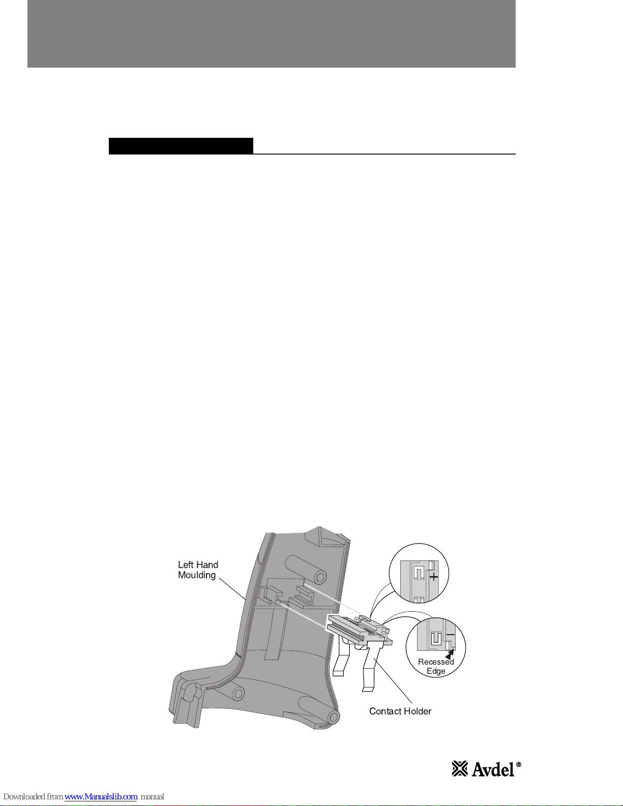
• Place the main internal mechanism into the left moulding 41, first ensuring that the electrical control circuit 5 and the
reservoir 73 are correctly placed within the mounting positions provided. The circuit board must be positioned so that the
heat sink is facing forward and the black and blue wires are at the top. The contact holder 4 must be positioned with the
positive symbol in the left moulding 41 as shown in the diagram below.
• The contact holder is designed to enable correct orientation in the mouldings. Care must be taken to ensure that the raised
portion on the right moulding 43 fits within the indent on the negative side of the contact holder 4.
• When replacing the right moulding 43 take care to ensure that no wires are trapped and correct alignment with the electrical
control circuit 5 and the vent screen 54 are achieved.
• When the moulded body is fully assembled with all eight pozi screws 45, insert new case label 42 on the right moulding 43.
IMPORTANT: Correct orientation of the contact holder 4 must be achieved when assembling into mouldings 41 and
43. Incorrect assembly will cause short circuit and failure of electrical control circuit.
MOULDED BODY ASSEMBLY
Left Hand
Moulding
Contact Holder
Recessed
Edge
 Loading...