

Page 1

3
YEARS OF MOWING
EXCELLENCE
Page 2

© 2002, Ransomes Jacobsen Limited. All Rights Reserved
Page 3

1 CONTENTS
CONTENTS P AGE
1 CONTENTS ................................................................................................................ 1
2 INTRODUCTION
2.1 IMPORT ANT ..............................................................................................................2
2.2 PRODUCT IDENTIFICATION....................................................................................... 2
3 SAFETY INSTRUCTIONS
3.1 OPERATING INSTRUCTIONS ..................................................................................... 3
3.2 SAFETY SIGNS .......................................................................................................... 3
3.3 STARTING THE ENGINE ............................................................................................. 3
3.4 DRIVING THE MACHINE ............................................................................................ 3
3.5 TRANSPORTING ........................................................................................................ 3
3.6 LEA VING THE DRIVING POSITION ............................................................................ 4
3.7 SLOPES..................................................................................................................... 4
3.8 BLOCKED CUTTING CYLINDERS .............................................................................. 4
3.9 ADJUSTMENTS, LUBRICA TION AND MAINTENANCE ............................................... 4
3.10 GUIDELINES FOR THE DISPOSAL OF SCRAP PRODUCTS ........................................7
4 SPECIFICA TIONS
4.1 ENGINE SPECIFICATION............................................................................................ 8
4.2 MACHINE SPECIFICA TION ........................................................................................ 8
4.3 DIMENSIONS .............................................................................................................8
4.4 VIBRA TION LEVEL .................................................................................................... 9
4.5 SLOPES..................................................................................................................... 9
4.6 RECOMMENDED LUBRICANTS ................................................................................. 9
4.7 CUTTING PERFORMANCE .........................................................................................9
4.8 CUTTING PERFORMANCE (AREA) ............................................................................ 9
4.9 CONFORMITY CERTIFICATES ................................................................................. 10
RANSOMES PARKWAY 2250 PLUS
SAFETY AND OPERATORS MANUAL
5 DECALS
5.1 SAFETY DECALS ..................................................................................................... 12
5.2 INSTRUCTION DECALS ............................................................................................12
6 CONTROLS
6.1 STARTER SWITCH ...................................................................................................13
6.2 THROTTLE CONTROL LEVER .................................................................................. 13
6.3 STEERING WHEEL RAKE ADJUSTMENT .................................................................. 13
6.4 FOOTPEDAL ............................................................................................................. 13
6.5 SPEED LIMITER ........................................................................................................ 1 3
6.6 TRANSPORT LATCHES............................................................................................ 14
6.7 P ARKING BRAKE ...................................................................................................... 14
6.8 HYDRAULIC LIFT LEVERS .......................................................................................14
6.9 UNIT COUNTER BALANCE CONTROL ...................................................................... 14
6.10 CUTTING UNIT SWITCHES ....................................................................................... 15
6.11 V ARIABLE CYLINDER SPEED ...................................................................................15
6.12 BACKLAPPING LEVER............................................................................................. 15
6.13 INSTRUMENT P ANEL ............................................................................................... 16
6.14 DIFF LOCK CONTROL .............................................................................................. 17
7 OPERA TION
7.1 DAIL Y INSPECTION .................................................................................................. 18
7.2 OPERATOR PRESENCE AND SAFETY INTERLOCK SYSTEM ................................... 19
7.3 OPERA TING PROCEDURE ......................................................................................... 20
7.4 STARTING THE ENGINE ............................................................................................ 21
7.5 DRIVING ................................................................................................................... 21
7.6 MOWING .................................................................................................................. 21
7.7 TO STOP THE ENGINE .............................................................................................. 21
7.8 PUSHING THE MACHINE WITH THE ENGINE STOPPED ............................................23
8 ADJUSTMENTS
8.1 HEIGHT OF CUT ....................................................................................................... 24
8.2 SEA T (GRAMMER GS85/90)..................................................................................... 25
8.3 SEA T (GRAMMER MSG 20) ..................................................................................... 26
9 MAINTENANCE
9.2 LUBRICATION AND MAINTENANCE CHART DIESEL POWERED MACHINES ............ 27
9.3 LUBRICATION AND MAINTENANCE CHART LPG POWERED MACHINES ................ 28
9.1 DAIL Y CHECKS ........................................................................................................ 29
10 GUARANTEE / SALES & SERVICE ............................................................................30
GB-1
Page 4

2 INTRODUCTION
RANSOMES PARKWAY 2250 PLUS
SAFETY AND OPERATORS MANUAL
2.1 IMPORTANT
IMPORTANT: This is a precision machine and the service obtained from it depends on the way it is
operated and maintained.
This SAFETY AND OPERATORS MANUAL should be regarded as part of the machine. Suppliers of both
new and second-hand machines are advised to retain documentary evidence that this manual was provided
with the machine.
This machine is designed solely for use in customary grass cutting operations. Use in any other way is
considered as contrary to the intended use. Compliance with and strict adherence to the conditions of
operation, service and repair as specified by the manufacturer, also constitute essential elements of the
intended use.
Before attempting to operate this machine, ALL operators MUST read through this manual and make
themselves thoroughly conversant with Safety Instructions, controls, lubrication and maintenance.
Accident prevention regulations, all other generally recognized regulations on safety and occupational
medicine, and all road traffic regulations shall be observed at all times.
Any arbitrary modifications carried out on this machine may relieve the manufacturer of liability for any
resulting damage or injury.
2.12 PRODUCT IDENTIFICATION
A Machine Name
B Serial Number
C Year of Manufacture
D Machine Weight
E Engine Power
GB-2
Page 5

3 SAFETY INSTRUCTIONS
RANSOMES PARKWAY 2250 PLUS
SAFETY AND OPERATORS MANUAL
This safety symbol indicates important safety
messages in this manual. When you see this
symbol, be alert to the possibility of injury, carefully
read the message that follows, and inform other
operators.
3.1 OPERATING INSTRUCTIONS
• Ensure that the instructions in this book
are read and fully understood.
• No person should be allowed to operate
this machine unless they are fully
acquainted with all the controls and the
safety procedures.
• Never allow children or people unfamiliar
with these instructions to usethis
machine. Local regulations may restrict
the age of the operator.
3.2 SAFETY SIGNS
• It is essential all safety labels are kept
legible, if they are missing or illegible they
must be replaced. If any part of the
machine is replaced and it originally
carried a safety label, a new label must be
affixed to the replacement part. New
safety labels are obtainable from
Ransomes dealers.
3.3 STARTING THE ENGINE
• Before starting the engine check that the
brakes are applied, drives are in neutral,
guards are in position and intact, and
bystanders are clear of the machine.
• Do not run the engine in a building without
adequate ventilation.
3.4 DRIVING THE MACHINE
• Before moving the machine, check to
ensure that all parts are in good working
order, paying particular attention to
brakes, tyres, steering and the security of
cutting blades.
• Replace faulty silencers, mow only in
daylight or good artificial light
• Always observe the Highway Code both on
and off the roads. Keep alert and aware at
all times. Watch out for traffic when
crossing or near roadways.
• Stop the blades rotating before crossing
surfaces other than grass.
• Remember that some people are deaf or
blind and that children and animals can
be unpredictable.
• Keep travelling speeds low enough for an
emergency stop to be effective and safe
at all times, in any conditions.
• Remove or avoid obstructions in the area
to be cut, thus reducing the possibility of
injury to yourself and/or bystanders.
• When reversing, take special care to
ensure that the area behind is clear of
obstructions and/or bystanders. DO
NOT carry passengers.
• Keep in mind that the operator or user is
responsible for accidents or hazards
occurring to other people or their
property.
• When the machine is to be parked,
stored or left unattended, lower the
cutting means unless the transport locks
are being used.
• While mowing, always wear substantial
footwear and long trousers. Do not
operate the equipment when barefoot or
wearing open sandals.
• Check the grass catcher frequently for
wear or deterioration. After striking a
foreign object. Inspect. the lawnmower
for damage and make repairs before
restarting and operating the equipment.
• If the machine starts to vibrate
abnormally, check immediately.
3.5 TRANSPORTING
• Ensure that the cutting units are
securely fastened in the transport
position. Do not transport with cutting
mechanism rotating.
• Drive the machine with due consideration
of road and surface conditions, inclines
and local undulations.
• Sudden decelerating or braking can
cause the rear wheels to lift.
• Remember that the stability of the rear of
the machine is reduced as the fuel is
used.
GB-3
Page 6

3 SAFETY INSTRUCTIONS
RANSOMES PARKWAY 2250 PLUS
SAFETY AND OPERATORS MANUAL
3.6 LEAVING THE DRIVING POSITION
• Park the machine on level ground.
• Before leaving the driving position, stop the
engine and make sure all moving parts are
stationary. Apply brakes and disengage all
drives. Remove the starter key.
3.7 SLOPES
TAKE EXTRA CARE WHEN WORKING ON
SLOPES
• Local undulations and sinkage will change
the general slope. Avoid ground conditions
which can cause the machine to slide.
• Keep machine speeds low on slopes and
during tight turns.
• Sudden decelerating or braking can cause
the rear wheels to lift. Remember there is
no such thing as a “safe” slope.
• Travel on grass slopes requires particular
care.
DO NOT USE ON SLOPES GREATER THAN 15°
IMPORTANT: When working on any slope set the
weight transfer, if fitted to its maximum (+) setting.
3.8 BLOCKED CUTTING CYLINDERS
• Stop the engine and make sure all moving
parts are stationary.
• Apply brakes and disengage all drives.
• Release blockages with care. Keep all parts
of the body away from the cutting edge.
Beware of energy in the drive which can
cause rotation when the blockage is released.
• Keep other people away from the cutting units
as rotation of one cylinder can cause the
others to rotate.
3.9 ADJUSTMENTS, LUBRICATION AND
MAINTENANCE
All vehicles
• Stop the engine and make sure all moving
parts are stationary.
• Apply brakes and disengage all drives.
• Read all the appropriate servicing instructions.
• Use only the replacement parts supplied by
the original manufacturer.
• When adjusting the cutting cylinders take
care not to get hands and feet trapped when
rotating cylinders.
• Make sure that other people are not touching
any cutting units, as rotation of one cylinder
can cause the others to rotate.
• To reduce the fire hazard, keep the engine,
silencer and battery compartments free of
grass, leaves or excessive grease.
• Replace worn or damaged parts for safety.
• When working underneath lifted parts or
machines, make sure adequate support Is
provided.
• Do not dismantle the machine without
releasing or restraining forces which can
cause parts to move suddenly.
• Do not alter engine speed above maximum
quoted in Engine Specification. Do not
change the engine governor settings or
overspeed the engine. Operating the engine
at excessive speed may increase the hazard
of personal injury.
• When servicing batteries, DO NOT SMOKE,
and keep naked lights away.
• Do not place any metal objects across the
terminals.
Diesel & Petrol vehicles
• When refuelling, STOP THE ENGINE, DO
NOT SMOKE. Add fuel before starting the
engine, never add fuel while the engine is
running.
• Use a funnel when pouring fuel from a can into
the tank.
• Do not fill the fuel tank beyond the bottom of
the filler neck.
• Replace all fuel tank and container caps
securely.
• Store fuel in containers specifically designed
for this purpose.
• Refuel outdoors only and do not smoke while
refuelling.
• If fuel is spilled, do not attempt to start the
engine but move the machine away from the
area of spillage and avoid creating any source
of ignition until fuel vapours have dissipated.
• Allow the engine to cool before storing in any
enclosure.
• Never store the equipment with fuel in the
tank inside a building where fumes may reach
an open flame or spark.
• If the fuel tank has to be drained, this should
be done outdoors.
• Do not spill fuel onto hot components.
LPG vehicles
• Only trained & competent personnel in the
use of LPG as a road vehicle fuel are
allowed to work on LPG aspects of the
vehicles engine or fuel system.
• When refuelling, STOP THE ENGINE, DO
NOT SMOKE. Add fuel before starting the
engine, never add fuel while the engine is
running.
• Vehicles should not be parked within 3
meters of any heat source, open flame or
other sources of ignition.
• Vehicles should not be serviced over an
inspection pit
GB-4
Page 7

3 SAFETY INSTRUCTIONS
• If for any reason a leak in the fuel system
is suspected, the vehicle should be moved
to an isolated area clear of buildings &
people and as far as possible from drains
and any source of ignition.
• The fuel filler bayonet on the vehicle should
be inspected regularly for any signs of
damage.
• The gas used to fill the vehicle must be
sourced from a reputable supplier.
• If a machine starts to vent gas when it is
running it should be moved to an area
away from any sources of ignition and
stopped. If it vents when static the
machine should not be started, all
potential sources of ignition should be
inhibited until the venting has stopped and
the local Ransomes Jacobsen dealer
should be contacted.
• Where practical LPG fuelled vehicles
should be parked in the open air, in a well
ventilated position. Where this is not
reasonably practical due to lack of space,
security ect. vehicles should be parked
inside suitably designed buildings or
garages. Please refer to HELA publication
LAC No. 52/6 rev
RANSOMES PARKWAY 2250 PLUS
SAFETY AND OPERATORS MANUAL
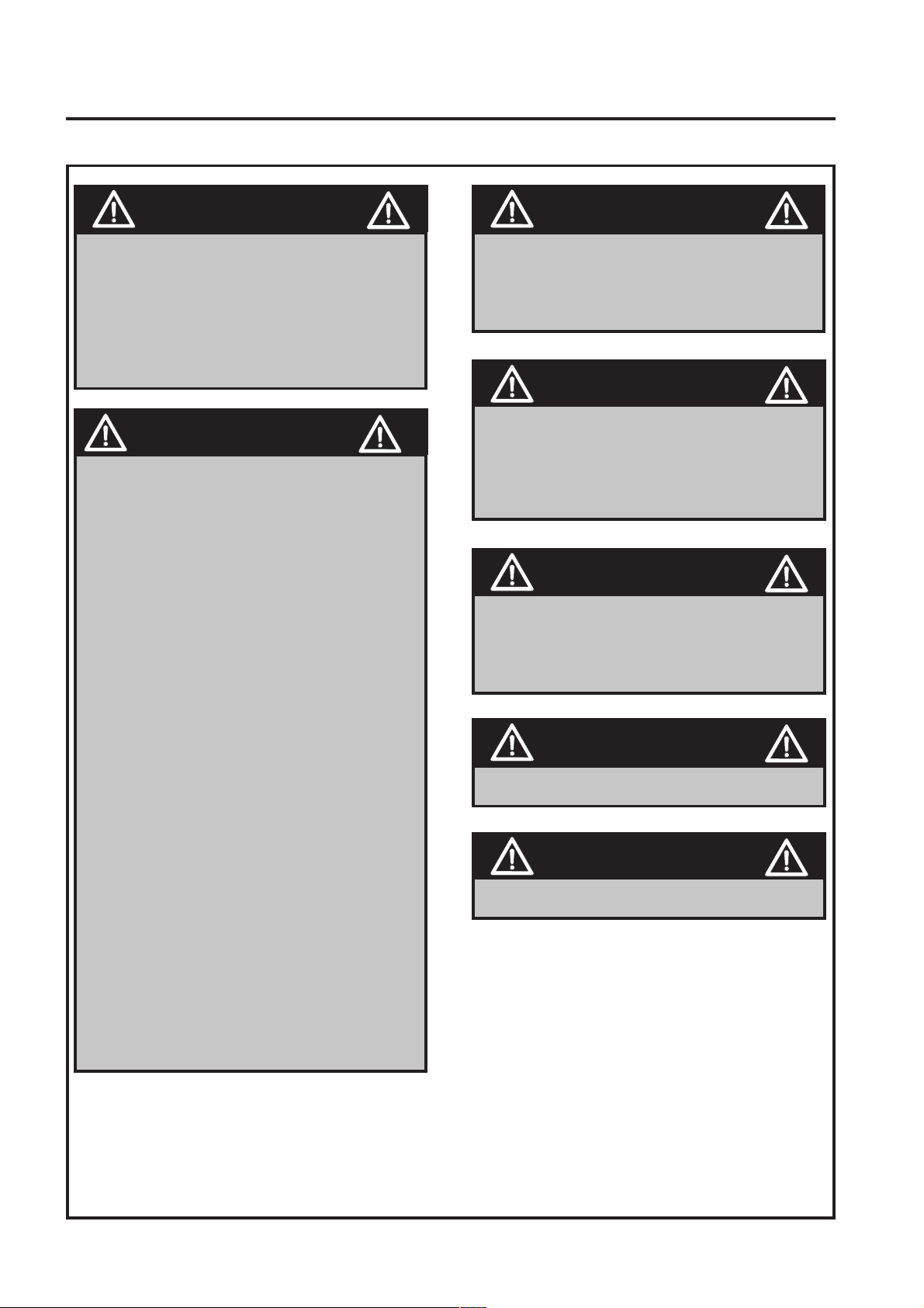
DANGER - Indicates an imminently hazardous
situation which, if not avoided, WILL result in death
or serious injury.
WARNING - Indicates a potentially hazardous
situation which, if not avoided, COULD result in
death or serious injury.
CAUTION - Indicates a potentially hazardous
situation which, if not avoided, MAY result in minor
or moderate injury and property damage. It may
also be used to alert against unsafe practices.
IMPORTANT: Transport speed is for highway
use only. Never select transport speed on grass
areas or uneven or unsurfaced roads or tracks.
The operating Instructions for the Cutting Units are
contained in a separate Publication .
GB-5
Page 8
3 SAFETY INSTRUCTIONS
RANSOMES PARKWAY 2250 PLUS
SAFETY AND OPERATORS MANUAL
WARNING
California Proposition 65
Engine Exhaust, some of its constituents,
and certain vehicle components contain
or emit chemicals known to the state of
California to cause cancer and birth
defects or other reproductive harm.
WARNING
Cutting Unit Transport Latches are a
Secondary Safety Devise.
When Transporting the machine the
Cutting units should be held in the
Transport position on the Hydraulics with
the Transport Latches Engaged.
1. Park the machine on level ground.
2. Whilst seated in the driving position
With the engine at operating speed
raise the cutting units fully by
operating lift levers, return the lever to
the neutral position.
WARNING
Batteries produce explosive gases and
contain corrosive acid and supply levels
of electrical current high enough to cause
burns.
WARNING
Battery posts, terminals and related
accessories contain lead and lead
compounds
WASH HANDS AFTER HANDLING
WARNING
Hydraulic Fluid escaping under pressure
can penetrate skin and do serious
damage. Immediate medical assistance
must be sought.
WARNING
DO NOT move the lever into the
lower position.
3. Disengage drives, stop the engine and
make sure all moving parts are
stationary. Apply brakes and remove
the starter key.
4. Transport latches can now be engaged
or released.
Before releasing transport latches
it is important that all cutting units
are fully raised.
DO NOT USE ON SLOPES GREATER THAN 15°
WARNING
VENTING GAS CAN CAUSE FROST BITE
GB-6
Page 9

3 SAFETY INSTRUCTIONS
RANSOMES PARKWAY 2250 PLUS
SAFETY AND OPERATORS MANUAL
3.10 GUIDELINES FOR THE DISPOSAL
OF SCRAP PRODUCTS
When it has been identified that a turf care
product has no further functional value and
requires disposal, the following actions should
be taken.
These guidelines should be used in
conjunction with applicable Health, Safety and
Environmental legislation and use of approved
local facilities for waste disposal and recycling.
• Position the machine in a suitable
location for any necessary lifting
equipment to be used.
• Use appropriate tools and Personal
Protective Equipment (PPE) and take
guidance from the technical manuals
applicable to the machine.
• Remove and store appropriately:
1. Batteries
2. Fuel residue
3. Engine coolant
4. Oils
• Disassemble the structure of the
machine referring to the technical
manuals where appropriate. Special
attention should be made for dealing
with ‘stored energy’ within
pressurised elements of the machine
or tensioned springs.
• Other worn out items should be
separated into material groups for
recycling and disposal consistent with
available facilities. More common
separation types are as follows:
• Steel
• Non ferrous metals
• Aluminium
• Brass
• Copper
• Plastics
• Identifiable
• Recyclable
• Non recyclable
• Not identified
• Rubber
• Items that cannot be separated
economically into different material
groups should be added to the
‘General waste’ area.
• Do not incinerate waste.
Finally update machinery records to indicate
that the machine has been taken out of service
and scrapped.
• Any items that still have a useful
service life as second hand
components or can be re-serviced
should be separated and returned to
the relevant centre.
GB-7
Page 10

4 SPECIFICATIONS
RANSOMES PARKWAY 2250 PLUS
SAFETY AND OPERATORS MANUAL
4.1 ENGINE SPECIFICATION
TYPE: Kubota 28Kw @ 3000rpm, 4
cylinder (in-line) vertical Diesel
engine, 4-stroke, water cooled,
1498cc, with 12v electric start.
Model: V1505-BBS-EC-1
Maximum Speed: 3000 +/-50 RPM (No load)
Idle Speed: 1500 +100/ -0 RPM
Oil Sump Capacity:6.4 litres
Fuel: No. 2-D Diesel fuel (ASTM D975)
Coolant Capacity: 5 litres 50/50 Anti-freeze
Coolant Specification:
Ethylene glycol anti-freeze with
softened water.
4.1.2 LPG
TYPE: Ford 25Kw @ 3000rpm, 4
cylinder (in-line) vertical Petrol
engine, 4-stroke, water cooled,
1297cc, with 12v electric start.
Model: VSG 413
Maximum Speed: 3150 ± 50 RPM (No load)
Idle Speed: 850 ± 50 RPM
Oil Sump Capacity: 3.1 litres
Fuel: LPG (Propane)
Coolant Capacity: 5 litres 50/50 Anti-freeze
Coolant Specification:
4.2 MACHINE SPECIFICATION
Frame construction:
Transmission:
Cutting unit drive:
Speeds:
Cutting: 12 km/h
Transport: 25 km/h
Reverse: 6 km/h
Steering: Hydrostatic powered steering to
Ethylene glycol anti-freeze with
softened water.
Heavy duty formed steel chassis.
Hydrostatic power provided by a
servo-controlled transmission
pump. Driving 4 indivdual wheel
motors with a patented parallel/
series transmission system.
Selectable forward all wheel drive
lock and reverse front axle diff
lock facility.
Hydraulic, with forward, neutral,
reverse control valve. Electric
dash mounted switch for on/off
control, with floor mounted switch
for cyclinder engage.Hand control
valve for reel speed adjustment
rear wheels.
Tyres:
Front - 26 x 12 -12 Dico Multi-Trac
Rear - 20 x 10 - 8 Multi-Trac
Pressures: All tyres 1.0 kg/cm
Ground pressure: 1.0 kg/cm
Brakes, Service: Positive hydrostatic braking.
Parking: Fail safe, Oil immersed wet disc
brakes.
Fuel Tank
Capacity Diesel: 45 Litres
Capacity LPG: 72 Litres
Hydraulic Tank
Capacity: 35 Litres
Battery: Exide 093
4.3 DIMENSIONS
Width of cut: 2.14 metres
Transport width: 1.6 metres
Overall height: 1.58metres
Overall length: 2.68 metres
Overall weight of
machine:
Diesel 1360*Kg
LPG 1388*Kg
* With 6 knife fixed head magna units, full fuel tank,
and optional Lighting and Beacon kits
Wheel Track: 1.6 metres
Wheel Base:1.5 metres
Uncut Circle:0.75 metres Radius
GB-8
Page 11

RANSOMES PARKWAY 2250 PLUS
SAFETY AND OPERATORS MANUAL
4.4 VIBRATION
The machine was tested for whole body and hand/arm
vibration levels. The operator was seated in the
normal operating postion with both hands on the
steering mechanism. The engine was running and the
cutting device was rotating with the machine
stationary.
Standard ISO 5349: 1986 Mechanical vibration.
Guidelines for the measurement and the
assessment of human exposure to hand-transmitted
vibration
sulP0522yawkraP
BWseireS
level
noitareleccAmrA/dnaH
eulaVtnanimoD
qeAXqeAYqeAZ
643,0493,0733,0
HRroHLxaM
2
s/msnoitareleccA
493,0
Standard ISO 2631-1: 1985 Evaluation of human
exposure to whole body vibration -- Part 1: General
requirements.
0522yawkraP
sulP
BWseireS
ydoBelohW
noitareleccA
level
naeM3520.00020.00070.09120.05210.03520.0
xyzxyz
noitacoLroolF
2
s/msnoitareleccA
noitacoLtaeS
2
s/msnoitareleccA
4.7 CUTTING PERFORMANCE
45 cuts per meter at 12 km/hr with 8 knife floating
head units.
62 cuts per meter at 12km/hr with 11 knife floating
head units.
23 cuts per meter at 12 km/hr with 4 knife fixed head
units.
34 cuts per meter at 12 km/hr with 6 knife fixed head
units.
4.8 CUTTING PERFORMANCE (AREA)
2.3 Hectares/hour at 12 km/hr with float head units.
2.3 Hectares/hour at 12 km/hr with fixed head units.
A 10% allowance is included for normal overlaps and
turning at the end of each cut.
4.5 SLOPES
DO NOT USE ON SLOPES GREATER THAN 15°
The slope 15° was calculated using static stability
measurements according to the requirements of
EN 836.
4.6 RECOMMENDED LUBRICANTS
Engine oil: Should be to MIL-L-2104C or to
A.P.I. Classification SE/SF/SG
grades. [10W-30]
ERUTAREPMETYTISOCSIVLIO
)F°93(C°4EVOBA03EAS
)F°93(C°4WOLEB03-W01ro03-W5EAS
Hydraulic Oil: Shell Tellus 46 to ISO VG46, or
equivilant
Grease: Shell Darina R2, or equivilant
GB-9
Page 12

4 SPECIFICATIONS
RANSOMES PARKWAY 2250 PLUS
SAFETY AND OPERATORS MANUAL
4.9 CONFORMITY CERTIFICATES
EC Declaration of Conformity Déclaration de Conformité CE
EG Conformiteits-Declaratie EG-Konformitatsbescheinigung
Certificato di Conformità CE EF Konformitetserklæring
EU Uppfyllandecertifikat Ilmoitus yhdenmukaisuudesta ey:n sääntöjen kanss
Declaración de Conformidad de la CE Declaração de Conformidade da CE
We the undersigned Nous, soussignés Wij, ondergetekenden Wir, die Unterzeichnenden Noi sottoscritti Undertegnede
Undertecknarna Me allekirjoittaneet Los abajo firmantes Nós, abaixo assinados
Ransomes Jacobsen Limited
Central Avenue, Ransomes Europark,
Ipswich, England, IP3 9QG
Declare that the machine Described Below Certifions que la machine suivante verklaren dat onderstaand beschreven machine
erklären, dass die nachfolgend beschriebene Maschine Dichiariamo che la macchina descritta di seguito Erklærer, at følgende maskine
Deklarerar att den maskin som beskrivs nedan vahvistamme, että alla kuvattu kone Certificamos que la máquina descrita abajo
declaramos que a máquina a seguir descrita
Make & Type Nom & Type Merk & Type Marke und Typ Marca e tipo
Fabrikat og type Fabrikat & typ Malli ja tyyppi Marca y Tipo Marca & Tipo.............. Ransomes Parkway 2250 Plus
Category Modèle Categorie Kategorie Categoria Kategori Luokka
Categoría Categoria ......................................................................................................... Ride on Cylinder Mower
Series Série Serie Sarja .............................................................................................. WB / CT
Engine Motor Moteur Motore Moottori ....................................................................... Kubota / Ford
Type Typ Tipo Tyyppi .................................................................................................. V1505-E / VSG413
Net Installed Power Puissance nette Netto geïnstalleerd vermogen
installierte Antriebsleistung Potenza installata netta Nettoeffekt installere
Installerad nettoeffekt Asennettu nettoteho Potencia instalada neta
Potência real instalada ....................................................................................................... 28KW / 25KW
Cutting Width Largeur de coupe Maaibreedte Schnittbreite
Larghezza di taglio Klippebredde Klippbredd Leikkuuleveys
Anchura de corte Potência real instalada ....................................................................... 214cm
Complies with the provisions of the following European directives and amendments and the regulations transposing it into national law
Est conforme aux prescriptions des normes, modifications et règles européennes suivantes voldoet aan de bepalingen van de volgende
Europese Richtlijnen en Amendementen, alsmede aan de verordeningen die deze omzetten in nationale wetgeving den Bestimmungen der
folgenden Europa-Richtlinien einschließlich aller Änderungen und Ergänzungen sowie den Vorschriften, die diese in das nationale Recht
umsetzen, entspricht soddisfa quanto previsto dalle seguenti direttive ed emendamenti europei e dalle normative che li riportano in legge
nazionale Overholder bestemmelserne i følgende EF-direktiver med ændringer og i de forordninger, hvorved de omsættes til national lov
Uppfyller kraven i följande europeiska direktiv med tillägg och regler transponerade till nationell lagstiftning täyttää seuraavana mainittujen
Euroopan direktiivien ja muutosten ja säännösten asettamat edellyt
Machinery Safety Directive Directive de sécurité des machines
Richtlijn Machineveiligheid Richtlinie zur Maschinensicherheit
Direttiva sulla sicurezza del macchinario Maskinsikkerhedsdirektivet
Maskinsäkerhetsdirektiv Koneen turvallisuutta koskeva direktiivi
Directiva de seguridad de maquinaria Directiva de segurança de máquinas ................ 98/37/EC
EMC Directive Directive de compatibilité électromagnétique EMC Richtlijn
EMK-Richtlinie Direttiva EMC EMC-direktivet Elektromagnetiskt kompatibilitetsdirektiv
EMC-direktiivi Directiva EMC............................................................................................. 89/336/EC
ROPS Directive Directive de ROPS ROPS Richtlijn ROPS-Richtlinie
Direttiva ROPS ROPS-direktivet ROPS direktiv ROPS-direktiivi Directiva ROPS ......86/298/EC
Noise in the Environment Directive Directiv Richtlijn Milieulawaa
Richtlinie zum Umgebungslärm Direttiva sulla rumorosità nellambiente
Støjemissionsdirektivet Bullerdirektiv Melu ympäristöä koskevassa direktiivissä
Directiva sobre ruido en el ambiente Directiva Ruído no Ambiente ................................ 2000/14/EC
Measured Sound Power Level Niveau de puissance sonore assuré
Gegarandeerd geluidsvermogenniveau Garantierter Schallleistungspege
Livello di potenza del suono misurato Målt lydeffektniveau Uppmätt ljudfraftsnivå
Mitattu åånitehon taso Nivel de Potencia Sonora Nívelde intensidade de som medido .. 101 dB(A) LWA
Guaranteed Sound Power Level Niveau de puissance sonore assuré
Gegarandeerd geluidsvermogenniveau Garantierter Schallleistungspege
Livello di potenza del suono misurato Garanteret lydeffektniveau
Garanterad ljudtrycksnivå Taattu äänitehon taso Nivel Garantizado de Potencia Sonora
Nível garantido de intensidade sonora .............................................................................. 105 dB(A) LWA
GB-10
Page 13

Conformity Assessment Procedure Procédure de conformitéévaluation Conformiteitsbeoordelingsprocedur Verfahren zur Beurteilung
der Konformität Procedura di valutazione conformità Procedure for overensstemmelsesvurdering Procedur för utvärderande av
uppfyllande Yhdenmukaisuuden arviointiproseduuri Procedimiento de evaluación de conformidad Processo de avaliação de
conformidade
Annex VI, Part 1 Annexe VI, Part 1 Bijlage VI, Part 1 Anlage VI, Part 1 Allegato VI, Part 1 Anneks VI, Part 1 Annex VI,
Part 1 Liite VI, Part 1 Anexo VI, Part 1 Anexo VI, Part 1
U.K. Notifiable Body (No.1088) Institut britannique à notifie(No.1088)r Britse onderzoeksinstantie (No.1088) in GB zu informierende
Institution (No.1088) Ente notificabile Gran Bretagna (No.1088) Organ, som skal underrettes (No.1088) Brittiskt meddelandeorgan
(No.1088) Ison-Britannian ilmoitusosapuoli (No.1088) Cuerpo notificable en el Reino Unido (No.1088) Entidade a notificar no Reino
Unido ( No.1088)
Sound Research Laboratories Limited
Holbrook House, Little Waldingfield
Sudbury, Suffolk CO10 0TH
Operator Ear Noise Level Bruit au niveau des oreilles de lopérateur
Geluidsniveau op oorhoogte bediener Schallpegel am Ohr des Fahrers
Livello rumorosità orecchio operatore Støjniveau ved betjening
Bullernivå vid operatörens öron Käyttäjän korvaan kohdistuva äänitaso
Nivel de ruido en el oido del operari Nível de ruído nos ouvidos do operador ...............85.3 dB(A)Leq (98/37/EC)
Complies with the following harmonised standard or technical provisions est conforme aux normes harmonisées Voldoet aan de
volgende geharmoniseerde norm of technische bepalingen Diese Maschine entspricht den folgenden harmonisierten Normen oder
technischen Bestimmungen Rispetta il seguente standard armonizzato o requisiti tecnici Overholder følgende harmoniserede
standardbestemmelser eller tekniske bestemmelser Uppfyller följande harmoniserade standard eller tekniska definitione täyttää
seuraavat harmonisoidut standardit tai tekniset edellytykset Cumple con los siguientes estándares de hramonización o provisiones
técnicas Está em conformidade com a norma harmonizada ou com as provisões técnicas seguintes
Machinery Safety Sécurité des machines Machineveiligheid
Maschinensicherhei Sicurezza del macchinario Maskinsikkerhed
Maskinsäkerhet Koneen turvallisuus Seguridad de maquinaria
Segurança de máquinas .................................................................................................... EN836
Hand Transmitted Vibration Vibrations transmises aux mains
Via de hand overgebrachte trilling Auf das Hand-Arm-System übertragene Schwingungen
Vibrazione trasmessa dalla mano Håndoverført vibration
Handöverförda vibrationer Käsivälitteinen tärinä Vibración transmitida a la mano
Vibrações transmitidas através das mãos ..................................................................... ISO 5349: 1986
Whole Body Vibration Vibrations du corps entier Trilling hele lichaam
Auf den gesamten Körper übertragene Schwingungen Vibrazione di tutto il corpo
Vibration i hele kroppen Hel kropps vibrationer Koko kehoon kohdistuva tärinä
Vibración de todo el cuerpo Vibração em todo o corpo ................................................. ISO 2631-1: 1985
ROPS .................................................................................................................................. OECD Code 4, ROPS Static Test
Keeper of Technical File, Place & Date of Declaration Lieu & Date de déclaration Plaats & datum verklaringsaflegging Ort und Datum
dieser Erklärung Luogo e data della dichiarazione Sted og dato for erklæringen Plats & datum för deklaration Lausunnon paikka ja
päivämäärä Lugar y fecha de la declaración Local e data da declaração
Technical Director
Ransomes Jacobsen Limited
Central Avenue, Ransomes Europark,
Ipswich, England, IP3 9QG
01.01.2004
T Lansdell
Technical Director
Certificate Number Numéro du certificat Certificaatnummer Zertifikat Nummer
Numero certificato Certifikatnummer Certifikat nummer Sertifikaattinumero
Número de certificado Número do Certificado
4117927 (Rev.3)
4 SPECIFICATIONS
RANSOMES PARKWAY 2250 PLUS
SAFETY AND OPERATORS MANUAL
GB-11
Page 14

5 DECALS
5.1 SAFETY DECALS
A903491 Read Operator's Manual.
A903489 Keep a Safe Distance from the
Machine.
A903492 Stay Clear of Hot Surfaces.
A903488 Do Not Open or Remove Safety
Shields While the Engine is Running.
A903494 Caution Rotating Blades.
A903493 Avoid Fluid Escaping Under Pressure.
Consult Technical Manual for Service
Procedures.
RANSOMES PARKWAY 2250 PLUS
SAFETY AND OPERATORS MANUAL
A903490 Do Not Remove Safety Shields While
Engine is Running.
A911410 Danger of Explosion if the Battery
Terminals are Short Circuited.
A911416 Maximum permitable working slope.
A911434 Caution Diesel fuel.
5.2 INSTRUCTION DECALS
1 Speed Limiter Position
2 Centre Cutting Unit Latch
3 Bonnet latch Point
4 Hydraulic Oil Filter
5 Parking Brake On/Off
6 Horn
7 Hydraulic Oil Level
9 Traction Foot Pedal Control
10 Unit Ground Weight Adjustment
11 Throttle Lever
GB-12
12 Tyre pressure
13 Cylinder Speed Adjustment
14 Cylinder Engage Foot Switch
15 Cylinder Engage Rocker Switch
16 Ignition Switch
18 Jacking Points
19 Hydraulic Oil Tank
20 Diesel Fuel Tank
22 Lift Points
Page 15

6 CONTROLS
6 CONTROLS
6.1 STARTER KEY SWITCH
The starter key (A) should be turned clockwise to the 'preheat' (No. 2) position to heat the glowplugs when the green
warning lamp goes out on warning lamp disply module turn
the starter key clockwise to the 'start' (No. 3) position to start
the engine. After starting, the key should be released and
allowed to return automatically to the 'on' (No. 1) position for
normal running.
6.2 THROTTLE CONTROL LEVER
The lever (B) should be moved away from the operator to
increase the engine speed and towards the operator to
decrease the engine speed.
NOTE: Engine should be used at full speed.
6.3 STEERING WHEEL RAKE ADJUSTMENT
The steering wheel is adjustable for rake. The clamping
release knob (A) is situated on the side of the control console
on the right hand side. To adjust turn the clamping knob
anticlockwise to release and pivot the steering wheel
backwards and forwards to obtain desired setting then lock
in position by turning clamping knob clockwise.
RANSOMES PARKWAY 2250 PLUS
SAFETY AND OPERATORS MANUAL
6.4 TRACTION FOOT PEDAL
To move the machine forward press the front of the foot
pedal (A). To reverse depress the rear of the foot pedal.
When the pedal is released it will return to its neutral
position.
6.5 SPEED LIMITER
The speed limiter (B) is operated by sliding the black
knob to the right or left. When slid to the right the
machine is limited to cutting speed, when slid to the left,
transport speed is available. In transport mode, reverse is
not available. When the speed limiter is in the mow speed
position four wheel drive is engaged.
IMPORTANT: To enable mow engage the speed
limiter must be in the cutting speed position. If
cutting units are rotating, moving the speed limiter
between the mow and transport positions will
engage and disengage cylinder rotation.
GB-13
Page 16

6 CONTROLS
6.6 TRANSPORT LATCHES
When transporting the machine ensure the cutting
units are raised and the transport latches (A) are
engaged.
6.7 PARKING BRAKES
The parking brake (B) is engaged when the lever is
moved toward the operator. The brake is fitted with a
micro switch that sensors brake position. The brake
must be applied to start the machine, and when
stopping and leaving the seat.
CAUTION:- The parking brake must not be
applied whilst the vehicle is moving.
6.8 HYDRAULIC LIFT LEVERS
The cutting units can be raised and lowered by three
control levers (A) situated on the right hand side of the
operators seat and can be operated as follows:
Centre lever controls Rear Unit No. 1
Right hand lever controls R.H. Unit No. 2
Left hand lever controls L.H. Unit No. 3
RANSOMES PARKWAY 2250 PLUS
SAFETY AND OPERATORS MANUAL
NOTE: If any unit is raised out of work then lowered into
work again the cylinder will not rotate until the mow foot
switch is depressed.
To lift: Move the lever(s) upwards and hold in position
until the units are at the required height.
To lower: Move the lever(s) fully downwards and release,
the unit(s) will lower to ground level. DO NOT hold lever
in down position.
NOTE: The units will only lift and lower when the engine
is running.
IMPORTANT: If, when cutting, a lift control lever is
accidently pulled up, the cutting units will not float over
ground undulations until the lever is pushed fully down
and allowed to return to neutral again.
6.9 UNIT COUNTERBALANCE CONTROL
Cutting unit ground pressure can be varied within
preset limits and is controlled by the handwheel (B)
on the right hand side of the operator's seat located
next to the lift/lower levers. The handwheel is turned
clockwise to reduce the groundweight of the cutting
unit, improving slope climbing ability.
The handwheel is turned anti clockwise to increase
the ground weight of the unit. Increased down
pressure will reduce the likelyhood of cutting unit
bounce when cutting undulating ground. When
cutting level ground the normal setting is midway
way between the maximum and minimum positions.
GB-14
Page 17

6 CONTROLS
6.10 CUTTING UNIT SWITCHES
To commence cutting ensure speed limiter is in
mow position and the cylinders have been lowered
Push bottom of the rocker switch (A) and depress
foot switch (B) Push top of rocker switch to stop
cutter unit rotation. (Cutting units stop rotating
automatically when raised.)
NOTE: The backlapping lever must be in the
drive position before cylinders wil rotate.
RANSOMES PARKWAY 2250 PLUS
SAFETY AND OPERATORS MANUAL
6.11 VARIABLE CYLINDER SPEED
The speed of rotation of the cutting cylinders is adjustable
by means of the handwheel (A) situated on the left hand
side of the operator. Cylinder speed should be set to
maximum in normal cutting conditions. In very long
growth conditions, cylinder speed should be reduced to
obtain best finish,cylinder speed should also be reduced
when cutting very short, dry grass to prevent excesive
cylinder and bottom blade wear. Rotate the hand wheel
clockwise to increase cylinder speed, anticlockwise to
decrease cylinder speed.
6.12 BACKLAPPING LEVER
The lever (B) sets cutting cylinder rotational direction
with three positions:
(a) fully towards the seat for mowing, (b) fully away
from the seat for backlapping and (c) set in the mid
position for neutral. See the separate cutting unit
operator's manual for an explanation of the
backlapping procedure.
GB-15
Page 18

6.13 INSTRUMENT PANEL
A. ENGINE PREHEAT INDICATOR LAMP
Colour green, on when the ignition switch is turned
clockwise to the pre-heat position. Once the lamp
goes out the engine can be started.
B. ENGINE TEMPARATURE GUAGE
Indicates current temparature of engine, whilst
running.
C. ENGINE OVERHEAT WARNING LAMP
Colour red, on when the engine temperature reaches a
preset level. If the lamp comes on and a warning horn
is sounded bring to machine to a stop, disengage the
cutting cylinders, apply the parking brake and allow
the engine to cool by running the engine at half speed
for two minutes before stopping and investigating the
cause.
RANSOMES PARKWAY 2250 PLUS
SAFETY AND OPERATORS MANUAL
D. CHARGING WARNING LAMP
Colour red, on when ignition is switched on and will go out
when the engine is started. If the light comes on while
the engine is running, the fan belt may be slipping or
broken or a fault in the electrical system is indicated and
should be investigated. STOP IMMEDIATELY.
E. ENGINE OIL PRESSURE WARNING LAMP
Colour red, on when the ignition is switched on, and will
go out once the engine has started. If the light comes on
while the engine is running - STOP IMMEDIATELY as
this indicates that the engine oil pressure is too low.
Check the level of oil in the sump and top up as
necessary. Check the oil pressure sender switch.
Continued operation may cause extensive damage to the
engine.
F. ROTATING BEACON
Press the bottom half of the switch to activate the
flashing beacon. (Where fitted)
G. HEAD LIGHT/SIDE LIGHT
Depress the bottom half of the switch to turn on the
headlights and sidelights. (Where fitted)
H. DIRECTIONAL INDICATORS
Depress left hand-side of switch to signal left, and
right hand-side of switch to signal right. (Where
fitted)
I. HAZARD WARNING LIGHTS.
Press the top half of the switch to turn on the hazard
warning lights. (Where fitted)
GB-16
Page 19

J. BLOCKED HYDRAULIC FILTER
INDICATOR.
Monitors Hyd filter condition. Colured red,
Illuminates prior to filter bypass valve operating,
when illuminated filter requires changing. The lamp
should illuminated while the engine is preheating as
a test. It is not unusual for the lamp to stay light for
up to 3 minutes after a very cold start. But should
not stay on for longer than 5 minutes.
K. HOURMETER
Located on the lefthand side of the steering tower,
above the parking brake . Records engine running
hours.
L. FUEL GUAGE
Located to the left of the engine temparature guage.
Monitors fuel level.
RANSOMES PARKWAY 2250 PLUS
SAFETY AND OPERATORS MANUAL
M. HORN
Press button to sound horn.
6.14 DIFF LOCK CONTROL
The Diff lock (A) is operated by depressing the foot
switch. When the foot switch is released the Diff
Lock ceases to operate. The Diff Lock should only
be used in severe situations, and should never be
used on tarmac or whilst steering
GB-17
Page 20

7 OPERATION
RANSOMES PARKWAY 2250 PLUS
SAFETY AND OPERATORS MANUAL
7.1 DAILY INSPECTION
CAUTION
The daily inspection should be performed
only when the engine is off and all fluids
are cold. Lower implements to the
ground, engage parking brake, stop
engine and remove ignition key.
1. Perform a visual inspection of the entire unit, look for signs of wear, loss hardwear and missing or
damaged components. Check for fuel and oil leaks to ensure connections are tight and hoses and
tubes are in good condition.
2. Check the fuel supply, radiator coolant level, crankcase oil level and air cleaner indicator. All fluids
must be at the full mark with the engine cold.
3. Make sure all cutting units are adjusted to the same height of cut.
4. Check all tyres for proper inflation.
5. Test the operator presence and safety interlock system.
GB-18
Page 21

7 OPERATION
RANSOMES PARKWAY 2250 PLUS
SAFETY AND OPERATORS MANUAL
7.2 OPERATOR PRESENCE AND SAFETY INTERLOCK SYSTEM
1. The operator presence & safety interlock system prevents the engine from starting unless the parking
brake is engaged, the mowing device is off and the operator is not in the seat. The system also
stops the engine if the operator leaves the seat with the mowing device engaged or the traction pedal
out of neutral.
WARNING
Never operate the equipment with the
operator presence & safety interlock
system disengaged or malfunctioning. Do
not disconnect or bypass any switch.
2. Perform each of the following tests to ensure the operator presence & safety interlock system is
functioning properly. Stop the test and have the system inspected and repaired if any of the tests
fail as listed below:
• The engine does start in test 1;
• The engine does not start during tests 2,3 or 4;
• The engine continues to run during test 5.
3. Refer to the chart below for each test and follow the check (ü) marks across the chart. Shut engine
off betwen each test.
Test1: Represents normal starting procedure. The operator is seated, parking brake is
engaged, the operators feet are off the pedals and the mower engagement device is off.
The engine should start.
Test 2: The engine must not start if the mower engage device is on.
Test 3: The engine must not start if the operator is not seated.
Test 4: The engine must not start if the traction pedal is depressed.
Test 5: Start the engine in the normal manner, push speed governor into Cut position, engage
mower switch on dash, engage cutting cylinders by depressing foot switch and lift
your weight off the seat.
tseT
rotarepO
detaeS
gnikraP
ekarB
deilppA
egagnEwoM
hctiwS
enignE
stratS
2
3
4
5
)7(nevesnihtiwgnitatorpotstsumstinugnittucehT.taesffothgiewruoytfiL
seYoNseYoNtuC
1
99999999999999999999
99999999999999999999
99999999999999999999
99999999999999999999
999999999999999
sdnoces
-siD
degagnE
seYoN
GB-19
Page 22

7 OPERATION
r
RANSOMES PARKWAY 2250 PLUS
SAFETY AND OPERATORS MANUAL
7.3 OPERATING PROCEDURE
CAUTION
To help prevent injury, always wear safety
glasses, leather work shoes or boots, a
hard hat and ear protection.
1. Under no circumstances should the engine be started without the operator seated on the tractor.
2. Do not operate tractor or attachments with loose, damaged or missing components. Whenever
possible mow when grass is dry
3. First mow in a test area to become thoroughly familiar with the operation of the tractor and control
levers.
Note: To prevent damage to the reel and bottom blade never operate the reels when they are not
cutting grass. Excessive friction and heat will develop between the bottom blade and reel
and damage the cutting edge.
4. Study the area to determine the best and safest operating procedure. Consider the height of the
grass, type of terrain, and condition of the surface. Each condition will require certain adjustments
or precautions.
5. Never direct discharge of material toward bystanders, nor allow anyone near the machine while in
operation. The owner/operator is responsible for injuries inflicted to bystanders and/or damage to thei
property.
CAUTION
Pick up all debris you can find before
mowing. Enter a new area cautiously
Always operate at speeds that allow you to
have complete control of the tractor
6. Use discretion when mowing near gravel areas (roadway, parking areas, cart paths, etc.). Stones
discharged from the implement may cause serious injuries to bystanders and/or damage the
equipment.
7. Disengage the drive motors and raise the implements when crossing paths or roads. Look out for
traffic.
8. Stop and inspect the equipment for damage immediately after striking an obstruction or if the
machine begins to vibrate abnormally. Have the equipment repaired before resuming operation.
GB-20
WARNING
Before you clean, adjust, or repair this
equipment, always disengage all drives,
lower implements to the ground, engage
parking brake, stop engine and remove
key from ignition switch to prevent injuries.
Page 23

7 OPERATION
RANSOMES PARKWAY 2250 PLUS
SAFETY AND OPERATORS MANUAL
WARNING
DO NOT USE ON SLOPES GREATER THAN 15°
9. Slow down and use extra care on hillsides. Read Section 3.7. Use caution when operating near drop
off points.
10. Never use your hands to clean cutting units. Use a brush to remove grass clippings from blades.
Blades are extremely sharp and can cause serious injuries
OPERATION OF THE
MACHINE
Read the Safety Instructions.
BEFORE OPERATING FOR THE FIRST TIME
• Check and adjust tyre pressure, if
necessary, to 1 kg/cm2.
• Add diesel fuel to tank if neccesary.
• Add LPG if neccesary, see self-Serve
Instructions below.
• Check engine oil and top-up, if necessary.
• Check radiator coolant and top-up, if
necessary (50% antifreeze solution).
• Make sure you understand the information
contained in the preceeding General
Instructions and Instruments & Controls
sections.
GB-21
Page 24

RANSOMES PARKWAY 2250 PLUS
SAFETY AND OPERATORS MANUAL
7.4 STARTING THE ENGINE
The following procedure is for starting cold engines.
1. Ensure the FWD/RVS pedal is in the
neutral position, the speed limiter is in the
transport position, the mow switch off, the
throttle setting is in a mid position and the
parking brake is applied.
2. Turn the ignition switch to position No.2
and hold until the glow plug light goes off
(5-10 sec.)
3. Turn ignition key fully clockwise to the
start position and operate the starter motor
until the engine starts (This should only
take a few seconds)
4. When the engine starts, release the key
immediately and it will return to the RUN
position.
5. If the engine does not start, preheat the
glow plugs and try again.
NOTES:
• Warm engine - When the engine is warm
because of surrounding temperature or
recent operation, step No.2 of the cold
engine starting procedure may be skipped
(no need to preheat glow plugs).
• If the engine fails to start after two tries
(with preheat if necessary), wait 20
seconds and try again.
• The starter motor should never be run
continuously for longer than 30 seconds
or it may fail.
7.5 DRIVING
• Release brake - Make sure the parking
brake is released before attempting to go
forward or reverse.
• Forward - Gently depress the top plate of
the FWD/RVS foot pedal to reach desired
ground speed.
• Reverse - Gently depress the bottom
plate of the FWD/RVS foot pedal to reach
desired ground speed.
• To stop - Gently return the FWD/RVS foot
pedal to the neutral position.
NOTES:
• Use complete foot to operate both forward
and reverse.
• Do not move pedal suddenly–always
operate slowly and smoothly. Never move
pedal violently from forward to reverse or
vice versa.
• Always keep foot firmly on the foot pedal–a
too relaxed foot control may result in a
jerky motion.
7.6 MOWING
1. Lower the reels with the cutting unit lift
control.
2. Ensure speed limiter is in mow position
3. Engage the cutting mechanism by pushing
on the lower half of cutting unit switch and
operating the floor mounted switch.
3. Release the parking brake and begin
driving forward.
NOTE: Always set the throttle to full for mowing,
even when the grass is heavy. When the
engine is labouring, reduce forward speed
by easing up on the FWD/RVS foot pedal.
Four wheel drive will only operate with the
speed limiter in the mow position.
7.7 TO STOP THE ENGINE
1. Disengage power to the cutting units with
the cutting unit switch.
2. Remove foot from the FWD/REV pedal.
3. Set the parking brake.
3. Move the throttle control lever to the
SLOW position.
4. Turn the ignition key to OFF.
WARNING
Cutting Unit Transport Latches are a
Secondary Safety Devise.
When Transporting the machine the
Cutting units should be held in the
Transport position on the Hydraulics with
the Transport Latches Engaged.
1. Park the machine on level ground.
2. Whilst seated in the driving position
With the engine at operating speed
raise the cutting units fully by
operating lift levers, return the lever to
the neutral position.
DO NOT move the lever into the
lower position.
3. Disengage drives, stop the engine and
make sure all moving parts are
stationary. Apply brakes and remove
the starter key.
4. Transport latches can now be engaged
or released.
Before releasing transport latches
it is important that all cutting units
are fully raised.
GB-22
Page 25

7 OPERATION
7.8 PUSHING THE MACHINE WITH THE ENGINE
STOPPED
1. To push, disengage the parking brake.
2. Turn screw (A) located on the underside of the
transmission pump 1 turn counterclockwise. Set
the steering wheel so that the rear wheels are
pointing straight ahead.
3. Remove the tower cover and turn the emergengy
brake valve( B) towards the parking brake/hour
meter side of the tower.
4. Turn the steering wheel to the left until resistance can be detected. The machine is now
ready to push. If unable to move the machine
apply further pressure to the steering wheel.
Excessive force should never be used on
the steering wheel.If the rear wheels start to
turn too much force is being applied.
5. After pushing, return valve (B) and knob (A) to
their previous positions.
RANSOMES PARKWAY 2250 PLUS
SAFETY AND OPERATORS MANUAL
GB-23
Page 26

8 ADJUSTMENTS
8.1 HEIGHT OF CUT
The height of cut can be set between:
13mm (1/2in) and 51mm (2in) (61mm on the spanner
adjust) on the Magna 250 fixed head.
13mm (1/2in) and 35mm (1 3/8in) on the Sport 200
floating head standard blade.
TO ADJUST HAND WHEEL TYPE:
1. Turn the adjuster handwheel (A) clockwise to
increase the height of cut, or anticlockwise to decrease
the height of cut.
2. Ensure that an equal amount of adjustment is made
to both adjusters on all the cutting units. To assist in
obtaining equal adjustment height of cut indicators (B)
are provided at each end of the roll assembly.
NOTE: The numbers 1 to 9 are only for reference from
one side of the roll to the other and bear no relation to
the height of cut other than each graduation gives
approximately 6.25mm (1/4in) height of cut movement
for fixed head units and 3.75mm (5/32in) for floating
head units. These indicators are set at the factory and
when the pointer is set the same at each end of the roll
the roll will be parallel with the bottom blade. If due to
any reason the roll and bottom blade are not parallel
with each other the roll can be set parallel with the
bottom blade by rotating one of the handwheels and
then one indicator adjusted by slackening the small
clamping screw in the centre of the indicator plate and
positioning the indicator relative to the pointer at the
opposite end of the roll assembly.
RANSOMES PARKWAY 2250 PLUS
SAFETY AND OPERATORS MANUAL
3. No other adjustments are necessary.
4. THIS IS A SELF LOCKING MECHANISM THERE
BEING NO NECESSITY TO UNLOCK OR LOCK THE
MECHANISM.
TO ADJUST SPANNER TYPE:
1 ) Release the two screws (C) which hold the
eccentric bush in the lever.
2 ) Turn the adjuster (B) at the rear of the unit,
clockwise to reduce the height of cut, or
anticlockwise to increase the height of cut.
3 ) After adjustment tighten screws
(C) to a maximum torque of 17Nm.
GB-24
Page 27

8 ADJUSTMENTS
8.2 SEAT
(GS85/90)
The seat can be adjusted for operator's weight and
leg reach to provide a comfortable position for
operating the machine.
1. ADJUSTMENT FOR OPERATOR WEIGHT
To Adjust:
The position of the adjusting knob (A) is on the front
of the seat, in the centre below the seat cushion. By
rotating the knob clockwise the weight capacity is
increased and by rotating the knob anticlockwise the
weight capacity is decreased.
2. FORE AND AFT ADJUSTMENT
To Adjust:
The position of the adjusting lever is on the right
hand side of the seat below the seat cushion (B). By
moving the lever towards the seat, the seat can be
slid backwards and forwards. When in the desired
position release the lever to locate in one of the pre
set positions.
RANSOMES PARKWAY 2250 PLUS
SAFETY AND OPERATORS MANUAL
3. BACK REST ADJUSTMENT
The back rest has three preset positions
To Adjust:
The position of the release lever is on the left hand
side of the seat back rest (C). Move the lever
upwards to move the upper part of the back rest
forward. Move the lever downwards to move the
upper part of the back rest rearwards.
NOTE:The seat is fitted with a microswitch to sense
operator presence. When the machine is fitted with a
ROPS frame or cab a lap belt is fitted and should be
worn at all times
GB-25
Page 28

8 ADJUSTMENTS
8.3 SEAT
(MSG20)
The seat can be adjusted for leg reach and back rest
angle to provide a comfortable position for operating the
machine.
1. FORE AND AFT ADJUSTMENT
To Adjust:
The position of the adjusting lever (B) is on the right
hand side of the seat below the seat cushion . By
pulling the lever away from the seat, the seat can be slid
backwards and forwards, when in the desired position
release the lever to locate in one of the pre set
positions.
2. BACK REST ADJUSTMENT
RANSOMES PARKWAY 2250 PLUS
SAFETY AND OPERATORS MANUAL
To Adjust:
The position of the release lever (A) is on the left
hand side of the seat. While sitting on the seat pull
the release lever upwards to release the back rest.
(The back rest is spring loaded to fold onto the seat
cushion.) Lean back to obtain the desired position
for the back rest and release the lever to locate in
one of the pre set positions.
3. WEIGHT ADJUSTMENT
To Adjust:
The position of the operator weight adjust lever (C) is
on the left hand side of the machine. To increase the
operator weight sitting slide the lever down while
sitting on the seat. To decrease the operator weight
setting pull the lever upwards.
NOTE:The seat is fitted with a microswitch to sense
operator presence. When the machine is fitted with a
ROPS frame or cab a lap belt is fitted and should be
worn at all times
GB-26
Page 29

9 MAINTENANCE
RANSOMES PARKWAY 2250 PLUS
SAFETY AND OPERATORS MANUAL
9.1 LUBRICATION AND MAINTENANCE CHART DIESEL POWERED MACHINES
serudecorpecnanatniampohskrowerastnioptellubetihW
yliaD
ENIGNE
levelliokcehC
lioegnahC
tnemeleretlifriakcehC
tnemeleretlifriaecalpeR
leveltnalooCkcehC
tnalooCegnahC
egdirtracretliflioecalpeR
retlifleufenilnicitsalpecalpeR
noitanimnatnoc
ENIHCAM
tnemevoM
ssenthgit
retawrofretlifleufkcehC
.retsinnacretlifleufecalpeR
neercsguBnaelC&kcehC
eerFrofladePnoissimsnarTkcehC
erusserperytkcehC
leveldiulfciluardyhkcehC
sirbedrofyabenignekcehC
ssenthgitrofstlob&stunkcehC
rofsgnittifciluardyhkcehC
noitidnocyrettabkcehC
tnemeleretlifciluardyhecalpeR sA
liociluardyhegnahC
z
z
z
z
z
z
z
z
/ylkeeW
yrevE
sruoh04
z
z
z
tsriF
05
sruoh
yrevE
001
sruoh
z z
z z
z
yrevE
002
sruoh
yrevE
004
sruoh
yrevE
008
sruoh
dnE
fo
nosaeS
z
z
z z
z
dnE/deriuqeR
nosaesfo
z
fodnerO
nosaes
esaerg2RaniraDllehShtiwgniwollofehtetacirbuL
toviPelxA
stoviPelxAbutS
)DW2(sgniraeBleehwraeR
dne-doRmaRgnireetS
sdne-doRegaknilgnireetS
stekcarbtoviptinU
stovipmratfiL
sgniraebrednilycgnittuC
sgniraeblloR
z
z
z
z
z
z
z
z
z
GB-27
Page 30

RANSOMES PARKWAY 2250 PLUS
SAFETY AND OPERATORS MANUAL
9.2 LUBRICATION AND MAINTENANCE CHART LPG POWERED MACHINES
serudecorpecnanatniampohskrowerastnioptellubetihW
yliaD
ENIGNE
levelliokcehC
lioegnahC
tnemeleretlifriakcehC
tnemeleretlifriaecalpeR
leveltnalooCkcehC
tnalooCegnahC
egdirtracretliflioecalpeR
neercsguBnaelC&kcehC
sgulPkrapSecalpeR
ENIHCAM
tnemevoM
erusserperytkcehC
z
z
z
z
eerFrofladePnoissimsnarTkcehC
z
z
/ylkeeW
yrevE
sruoh04
yrevE
002
sruoh
yrevE
004
sruoh
yrevE
008
sruoh
dnE
fo
nosaeS
z
z
z
z
z
leveldiulfciluardyhkcehC
sirbedrofyabenignekcehC
ssenthgitrofstlob&stunkcehC
rofsgnittifciluardyhkcehC
ssenthgit
noitidnocyrettabkcehC
tnemeleretlifciluardyhecalpeR sA
liociluardyhegnahC
toviPelxA
stoviPelxAbutS
)DW2(sgniraeBleehwraeR
dne-doRmaRgnireetS
sdne-doRegaknilgnireetS
stekcarbtoviptinU
z
z
z
z
z
dnE/deriuqeR
nosaesfo
z
esaerg2RaniraDllehShtiwgniwollofehtetacirbuL
fodnerO
nosaes
z
z
z
z
z
z
GB-28
stovipmratfiL
sgniraebrednilycgnittuC
sgniraeblloR
z
z
z
Page 31

9 MAINTENANCE
9.3 DAILY CHECKS (Every 8 working hours)
Oil Level.
Check level of oil in sump. Remove dipstick (A) wipe
and replace and check that oil is up to the
maximum mark. Top up with SAE30 if neccesary. It
is important that this test is carried out with the
engine cold and vehicle parked on level ground.
Air Filter.
Examine blockage indicator (B) If indicator shows
red filter element requires cleaning or replacement.
The indicator is reset bt pressing the button on the
end of the indicator.
Hydraulic Oil Level.
Check hydraulic oil level in tank. The level of oil
should be maintained so it is just visible in the sight
tube (C) Top up with Tellus 46 or equivilant if
neccesary. The oil level should be checked cold with
the machine parked on level ground.
RANSOMES PARKWAY 2250 PLUS
SAFETY AND OPERATORS MANUAL
IMPORTANT:
Absolute cleanliness must be observed when
filling the hydraulic tank. Oil must be filtered
through a 25micron filter before entering the
hydraulic tank.
Cooling System.
Check coolant level in expansion tank (D) The
coolant level should be between the marks indicated
on the bottle. Top up if neccesary using a 50%
antifreeze solution.
NOTE: To avoid the risk of accidental injury
the seat plate and bonnet are fitted
with locks. These should be kept
secure when access is not required.
Cleaning the air filter
Remove loose dirt from element with compressed air
working from the "clean" to "dirty" side.
Note: Compressed air must not exceed 6bar,
with the nozzle 50mm away from element.
The element should be replaced after 6
cleanings.
Cooling System.
Check Bug Screen (E) is free from dust and
there is an un-interupted air flow to engine. The
screen should be fitted with the mesh facing the rear
of the machine. Any deris should be removed with a
soft hand brush.
GB-29
Page 32

10 GUARANTEE / SALES & SERVICE
RANSOMES PARKWAY 2250 PLUS
SAFETY AND OPERATORS MANUAL
GUARANTEE
We GUARANTEE that should any defect in workmanship or material occur in the
goods within TWO YEARS or two thousand hours (on models equipped with hour
meters), or whichever occurs first.
Exception to this warranty will be Aeration products, which are covered for a period
of TWO-YEARS or five hundred hours (on models equipped with hour meters) or
whichever occurs first.
We will repair, or at our option, replace the defective part without making any charge
for labour or for materials, provided that the claim under this guarantee is made
through an authorised dealer and that the defective part shall, if we so request, be
returned to us or to the dealer.
This guarantee is in addition to, and does not exclude, any condition or warranty
implied by law, except that we accept no liability in respect of used/second-hand
goods, or in respect of defects which in our opinion are in any way or to any extent
attributable to misuse, lack of reasonable care or ordinary wear and tear, or to the
fitting of spares, replacements, or extra components which are not supplied or
approved by us for the purpose. The use of non-recommended oil or lubricant
nullifies the guarantee.
Damage through transport or normal wear does not come under the guarantee.
The warranty is extended to the original purchaser only and is not transferable to
subsequent owners. The warranty period begins on the date the product is delivered
to the end user (customer), unless otherwise agreed with the manufacturer. At the
end of the first year the owner must have the product serviced by an authorised
dealer to be eligible for the second year of warranty coverage.
SALES & SERVICE
A network of authorised Sales and Service dealers has been established and these
details are available from your supplier.
When service attention, or spares, are required for the machine, within or after the
guarantee period your supplier or any authorised dealer should be contacted.
Always quote the registered number of the machine.
If any damage is apparent when delivery is made, report the details at once to the
supplier of the machine.
KEY NUMBERS. It is recommended that all key numbers are noted here:
Starter Switch :- ...............
Diesel tank :- ...............
It is also recommended that the machine and engine numbers are recorded.
The machine serial number is located on the registration plate and the engine serial
number can be found under the exhaust maifold above the starter motor.
Machine Number :- ...............
Engine Number :- ...............
GB-30
Page 33

Page 34

World Class Quality, Performance and Support
Equipment from Ransomes Jacobsen Limited is built to
exacting standards ensured by ISO 9001 registration at
all our manufacturing locations. A worldwide dealer
network and factory-trained technicians backed by
Ransomes Jacobsen Parts Xpress provide reliable,
high-quality product support.
BOB-CAT BUNTON CUSHMAN JACOBSEN RANSOMES RYAN E-Z-GO
Ransomes Jacobsen Limited
Central Avenue, Ransomes Europark, Ipswich, England, IP3 9QG
English Company Registration No. 1070731
www.ransomesjacobsen.com
 Loading...