

Textron MPE 850 OFF-ROAD Repair Manual
TD410023
Rev B
18.04.2017
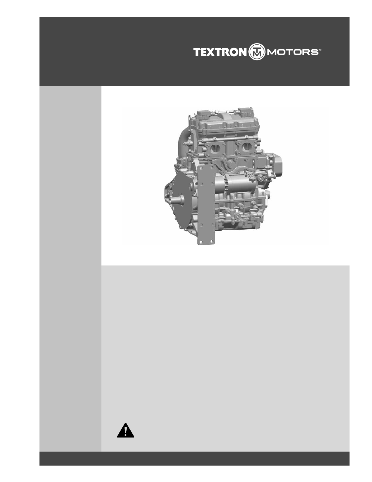
MPE 850 OFF-ROAD
– 409135 I2 846 UTV NA-80
– 410750 I2 846 UTV NA-80
This repair manual is valid for the following engine models:
en_English
REPAIR MANUAL
4-Stroke Engine
Read the introductory chapter before performing the task on the engine.
Pay particular attention to the safety messages.

TEXTRON MOTORS GmbH
Daimlerstraße 5
88677 Markdorf
Germany
WWW.TEXTRONMOTORS.COM
CALIFORNIA Proposition 65 Warning
This engine and engine exhaust contains chemicals known to the State of California to cause cancer, birth
defects, or other reproductive harm.
TEXTRON MOTORS GmbH strives to make continual improvements as part of the ongoing technical
development of its products. All documentation is therefore subject to technical modifications.
Reprints and translations, in whole or in part, require written permission from TEXTRON MOTORS GmbH.
All rights reserved according to the copyright law.

3TD410023-B RLF
TABLE OF CONTENTSTABLE OF CONTENTS
ABOUT THIS DOCUMENT 5
Meaning of the symbols and signal words . . . . . . 5
Change management. . . . . . . . . . . . . . . . . . . . . . 5
SAFETY 6
Meaning of the safety alert symbol and signal
words . . . . . . . . . . . . . . . . . . . . . . . . . . . . . . . . . . 6
Important safety messages . . . . . . . . . . . . . . . . . 6
BEFORE YOU BEGIN WORKING 9
Engine identifikation . . . . . . . . . . . . . . . . . . . . . . . 9
Engine components . . . . . . . . . . . . . . . . . . . . . . . 9
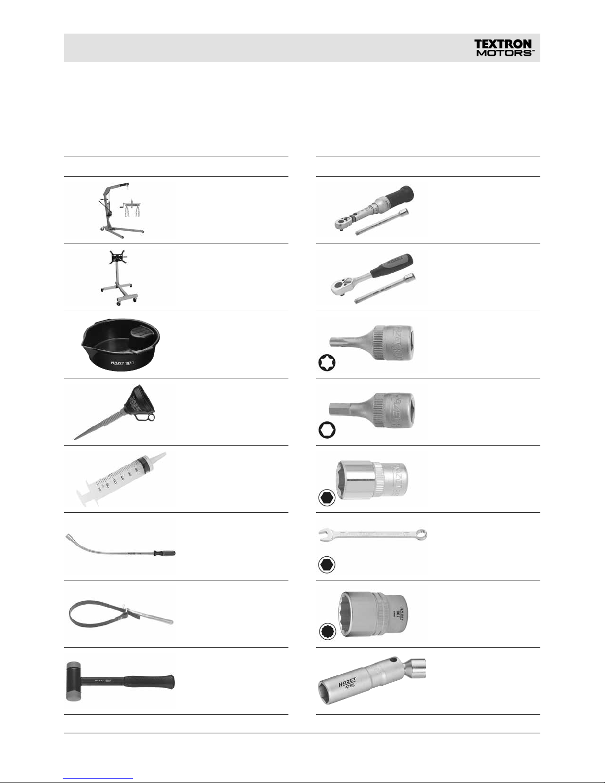
Workshop equipment . . . . . . . . . . . . . . . . . . . . . 11
TEXTRON MOTORS Special tools . . . . . . . 11
Workshop equipment and tools . . . . . . . . . . 12
Supplies . . . . . . . . . . . . . . . . . . . . . . . . . . . . 14
SECTION A – ENGINE DISASSEMBLY 16
Removing engine from the vehicle . . . . . . . . . . . 18
Securing the engine . . . . . . . . . . . . . . . . . . . . . . 18
Mount the engine across from the drive side . . . 18
Removing generator cover . . . . . . . . . . . . . . . . . 19
Removing starter . . . . . . . . . . . . . . . . . . . . . . . . 19
Removing intake manifold . . . . . . . . . . . . . . . . . 20
Removing ignition coils. . . . . . . . . . . . . . . . . . . . 21
Removing spark plugs . . . . . . . . . . . . . . . . . . . . 21
Removing valve cover . . . . . . . . . . . . . . . . . . . . 21
Removing rocker arms . . . . . . . . . . . . . . . . . . . . 22
Mount the engine on the drive side . . . . . . . . . . 22
Removing oil cooler . . . . . . . . . . . . . . . . . . . . . . 23
Removing oil cooler bracket . . . . . . . . . . . . . . . . 23
Removing impeller . . . . . . . . . . . . . . . . . . . . . . . 24
Removing slide ring seal . . . . . . . . . . . . . . . . . . 24
Removing crankshaft cover . . . . . . . . . . . . . . . . 24
Removing crankshaft sensor . . . . . . . . . . . . . . . 25
Mount the engine across from the drive side . . . 25
Removing generator and stub shaft . . . . . . . . . . 25
Removing oil pressure pump . . . . . . . . . . . . . . . 26
Mount the engine on the drive side . . . . . . . . . . 27
Removing suction pump cover . . . . . . . . . . . . . . 27
Removing suction pump intermediate gear . . . . 28
Removing timing chain . . . . . . . . . . . . . . . . . . . . 28
Removing cylinder head. . . . . . . . . . . . . . . . . . . 29
Removing crank drive. . . . . . . . . . . . . . . . . . . . . 30
Removing thermostat housing . . . . . . . . . . . . . . 32
Removing chain guide . . . . . . . . . . . . . . . . . . . . 32
Removing chain rail . . . . . . . . . . . . . . . . . . . . . . 32
Replacing piston or con rod . . . . . . . . . . . . . . . . 33
Removing and reinstalling cylinder liners . . . . . . 33
SECTION B – ENGINE RESASSEMBLY 36
Mount the engine on the drive side . . . . . . . . . . 38
Replacing oil filter . . . . . . . . . . . . . . . . . . . . . . . . 38
Installing chain rail . . . . . . . . . . . . . . . . . . . . . . . 38
Installing chain guide . . . . . . . . . . . . . . . . . . . . . 39
Installing thermostat housing . . . . . . . . . . . . . . . 39
Installing crank drive. . . . . . . . . . . . . . . . . . . . . . 39
Installing cylinder head. . . . . . . . . . . . . . . . . . . . 44
Installing timing chain. . . . . . . . . . . . . . . . . . . . . 45
Installing suction pump intermediate gear . . . . . 47
Installing suction pump cover . . . . . . . . . . . . . . . 47
Mount the engine across from the drive side . . . 48
Installing crankshaft oil seal . . . . . . . . . . . . . . . . 48
Installing oil pressure pump . . . . . . . . . . . . . . . . 50
Installing generator and stub shaft . . . . . . . . . . . 51
Mount the engine on the drive side . . . . . . . . . . 52
Installing crankshaft sensor . . . . . . . . . . . . . . . . 52
Installing crankshaft cover . . . . . . . . . . . . . . . . . 52
Installing slide ring seal . . . . . . . . . . . . . . . . . . . 53
Installing impeller . . . . . . . . . . . . . . . . . . . . . . . . 55
Installing oil cooler bracket . . . . . . . . . . . . . . . . . 55
Installing oil cooler . . . . . . . . . . . . . . . . . . . . . . . 56
Mount the engine across from the drive side . . . 56
Installing rocker arms . . . . . . . . . . . . . . . . . . . . . 57
Installing valve cover . . . . . . . . . . . . . . . . . . . . . 57
Installing spark plugs . . . . . . . . . . . . . . . . . . . . . 58
Installing ignition coils. . . . . . . . . . . . . . . . . . . . . 58
Installing intake manifold . . . . . . . . . . . . . . . . . . 59
Installing starter . . . . . . . . . . . . . . . . . . . . . . . . . 60
Installing generator cover . . . . . . . . . . . . . . . . . . 61
Securing the engine . . . . . . . . . . . . . . . . . . . . . . 63
Installing engine into the vehicle. . . . . . . . . . . . . 63
Completing and checking of the work. . . . . . . . . 63

4 TD410023-B RLF
TABLE OF CONTENTS
SECTION C – ADDITIONAL WORKING
INSTRUCTIONS 64
Intake manifold disassembly . . . . . . . . . . . . . . . 65
Removing throttle body . . . . . . . . . . . . . . . . 65
Removing intake manifold sensor . . . . . . . . 65
Intake manifold reassembly . . . . . . . . . . . . . . . . 66
Installing intake manifold sensor . . . . . . . . . 66
Installing throttle body . . . . . . . . . . . . . . . . . 66
Valve cover disassembly . . . . . . . . . . . . . . . . . . 67
Removing camshaft sensor . . . . . . . . . . . . . 67
Valve cover reassembly . . . . . . . . . . . . . . . . . . . 67
Installing camshaft sensor . . . . . . . . . . . . . . 67
Suction pump cover disassembly. . . . . . . . . . . . 68
Removing oil suction pump . . . . . . . . . . . . . 68
Suction pump cover reassembly . . . . . . . . . . . . 68
Installing oil suction pump . . . . . . . . . . . . . . 68
Cylinder head disassembly. . . . . . . . . . . . . . . . . 69
Removing knock sensor . . . . . . . . . . . . . . . . 69
Removing brackets and oil pressure switch . 69
Removing camshaft . . . . . . . . . . . . . . . . . . . 70
Removing valves . . . . . . . . . . . . . . . . . . . . . 70
Removing fuel rail. . . . . . . . . . . . . . . . . . . . . 71
Cylinder head reassembly . . . . . . . . . . . . . . . . . 72
Installing fuel rail. . . . . . . . . . . . . . . . . . . . . . 72
Installing valves . . . . . . . . . . . . . . . . . . . . . . 73
Installing camshaft . . . . . . . . . . . . . . . . . . . . 74
Installing brackets and oil pressure switch . . 75
Installing knock sensor . . . . . . . . . . . . . . . . . 76
Thermostat housing disassembly. . . . . . . . . . . . 76
Removing thermostat . . . . . . . . . . . . . . . . . . 76
Removing coolant sensor. . . . . . . . . . . . . . . 77
Thermostat housing reassembly . . . . . . . . . . . . 77
Installing coolant sensor. . . . . . . . . . . . . . . . 77
Installing thermostat . . . . . . . . . . . . . . . . . . . 77
SECTION D – SPEZIFICATIONS 80
Tightening torques und assembly instructions . . 81
Other bolts . . . . . . . . . . . . . . . . . . . . . . . . . . 83
Screw-in nipples . . . . . . . . . . . . . . . . . . . . . . 84
Screw-in plugs . . . . . . . . . . . . . . . . . . . . . . . 84
Liquid sealing contours. . . . . . . . . . . . . . . . . . . . 85
Liquid sealing contour crankcase . . . . . . . . . 85
Liquid sealing contour suction pump cover . 86
Liquid sealing contour thermostat housing. . 87
Liquid sealing contour generator cover . . . . 88
Test procedures and adjustments. . . . . . . . . . . . 89
Valve lash . . . . . . . . . . . . . . . . . . . . . . . . . . . 89
Spark plug gap . . . . . . . . . . . . . . . . . . . . . . . 89
Con rod bearing play . . . . . . . . . . . . . . . . . . 90
Main bearing play . . . . . . . . . . . . . . . . . . . . . 90
Valve timing . . . . . . . . . . . . . . . . . . . . . . . . . 90
Generator . . . . . . . . . . . . . . . . . . . . . . . . . . . 91
Oil pressure . . . . . . . . . . . . . . . . . . . . . . . . . 92
Tie rod thread protusion . . . . . . . . . . . . . . . . 93
Thermostat . . . . . . . . . . . . . . . . . . . . . . . . . . 93
Crankshaft sensing wheel . . . . . . . . . . . . . . 94
Rocker arm cam spike . . . . . . . . . . . . . . . . . 94
OVERVIEW OF REVISIONS 96

5TD410023-B RLF
ABOUT THIS DOCUMENTABOUT THIS DOCUMENT
This repair manual describes how to step by step safely and professionally disassemble the engine and
reassemble.
After the introductory chapters the repair manual is divided into four major sections.
Section A This section describes how the engine can be disassembled right down to the spare part level.
Section B This section describes how the engine can be reassembled.
Section C This section describes how the assemblies can be disassemble and reassemble that have not
been fully disassembled in section A.
Section D This section contains specifications, such as test procedures, adjustments, tightening torques,
and assembly instructions.
Observe the following references:
– Owner’s Manual provided with your vehicle for general operation and maintenance instructions and other
important information.
– Always you also need the vehicle manufacturer's documentation.
– Keep the spare parts catalog for the engine ready. The spare parts catalog contains for example
information on components that have to be replaced after removal.
– Information on troubleshooting can be found in the engine diagnostic manual.
– Some figures in this repair manual are general illustrations and may differ from the actual engine.
MEANING OF THE SYMBOLS AND SIGNAL WORDS
Item Meaning
NOTICE The signal word NOTICE indicates potential property damage.
Information The signal word Information indicates specific features and recommendations.
CHANGE MANAGEMENT
TEXTRON MOTORS GmbH strives to make continual improvements as part of the ongoing technical
development of its products. Therefore descriptions in the repair manual can be changed or added. All
changes are described in the chapter Overview of revisions.
Observe the following references:
– Always use the most current repair manual on WWW.TEXTRONOFFROAD.COM.

6 TD410023-B RLF
SAFETYSAFETY
This engine is state-of-the-art and built according to recognized safety-technical regulations. Ignoring the
information in this repair manual may result in personal injury or property damage.
This repair manual is solely intended for use in a workshop authorized by TEXTRON OFF ROAD. All tasks
on the engine must be performed by appropriately trained personnel.
Before beginning any work, trained personnel authorized to work on the engine must have access to the
complete documentation of the engine. Ensure that all the introductory chapters, in particular the chapter on
safety, have been read and understood.
Observe all generally applicable laws and regulations in addition to the information in this repair manual:
– Accident prevention
– Environmental protection
– Handling of hazardous materials
– Personal safety equipment
– Traffic laws
MEANING OF THE SAFETY ALERT SYMBOL AND SIGNAL WORDS
Item Meaning
The safety alert symbol draws your attention to possible dangers.
WARNING
The signal word WARNING indicates a potentially dangerous situation that may
lead to a serious or fatal injury.
CAUTION
The signal word CAUTION indicates a potentially dangerous situation that may
lead to a minor or moderately severe injury.
IMPORTANT SAFETY MESSAGES
Defective components may pose a safety risk.
► Check all parts before installation and replace defective components.
Work performed incorrectly poses a safety risk to persons.
► Check the vehicle each time after working on the engine.
Defective components
Checking the work carried out

7TD410023-B RLF
SAFETY
All the components in your engine have been carefully tested and fulfill
strict quality and safety requirements.
► TEXTRON OFF ROAD offers spare parts to the highest quality.
Ensure that equivalent spare parts corresponds with this quality
requirements.
Engine modifications may pose a safety risk.
► Do not install add-on parts or modify the engine.
Spinal column injury due to incorrect lifting of heavy loads.
► Always use a workshop crane to lift and transport the engine on the
brackets provided.
Crush injuries due to the engine overturning.
► Secure the engine before starting any work.
► Mount the engine as soon as possible to the engine stand.
► Hold the engine as long as with the workshop crane until the engine is
mounted on the engine stand.
Unsuitable tools and accessories pose a safety risk.
► Always use the tools and accessories listed in chapter Workshop
equipment.
Missing protective equipment poses a safety risk.
► Attach all protective equipment after completing the tasks.
We assume for all work that the engine is disconnected from the power
supply. Leaving the engine connected to the power supply poses a risk to
personnel.
► Only reconnect the power supply when prompted to do so by the
vehicle manufacturer.
► Pay attention to the safety messages in the vehicle manufacturer's
documentation.
Engine exhaust gases contain carbon monoxide (CO). Inhalation of
carbon monoxide can deprive the body of oxygen and result in organ
damage or even death by asphyxiation.
► Never operate the engine in enclosed spaces.
Spare parts
Add-on parts and modifications
Lift and transport the engine
Securing the engine
Tools and accessories
Protective equipment
Engine power supply
Engine exhaust gases

8 TD410023-B RLF
SAFETY
Operating materials pose a health risk.
► Always read the manufacturer's instructions.
► Always wash your hands immediately after working on or around an
engine.
Operating materials are hazardous to the environment.
► Never allow operating materials to escape into the groundwater, water
courses or sewage system. Always dispose of engine fluids according
to applicable regulations.
Danger of slipping on spilled fluids.
► Place a drain tray.
► Always clean up any spilled engine fluids immediately.
► Always use a filler neck or funnel when filling the engine with fluids.
Fuel is highly flammable. Vapors may ignite and cause an explosion.
► Do not smoke in the vicinity of the engine and do not allow naked
flames or sparks near the engine or the fuel system.
► Always turn off the engine before fueling.
► Never fill with fuel while the engine is running.
► Do not start the engine if there is a smell of fuel or you suspect that
fuel is leaking.
► Fuel on hot surfaces can cause fires.
► In the event of a fire, use foam, dry chemical or carbon dioxide
extinguishers. Do not extinguish with water.
Engine oil is flammable and can emit toxic gases.
► Do not smoke in the vicinity of the engine and do not allow open
flames or sparks near the engine.
► Engine oil on hot surfaces can cause fires.
► Do not extinguish with water. In the event of a fire, use foam, dry
chemical or carbon dioxide extinguishers.
Fuel, engine oil and coolant
handling
Fuel
Engine oil
9TD410023-B RLF
1
3
2
5
4
3
2
4
1
6
5
7
BEFORE YOU BEGIN WORKINGBEFORE YOU BEGIN WORKING
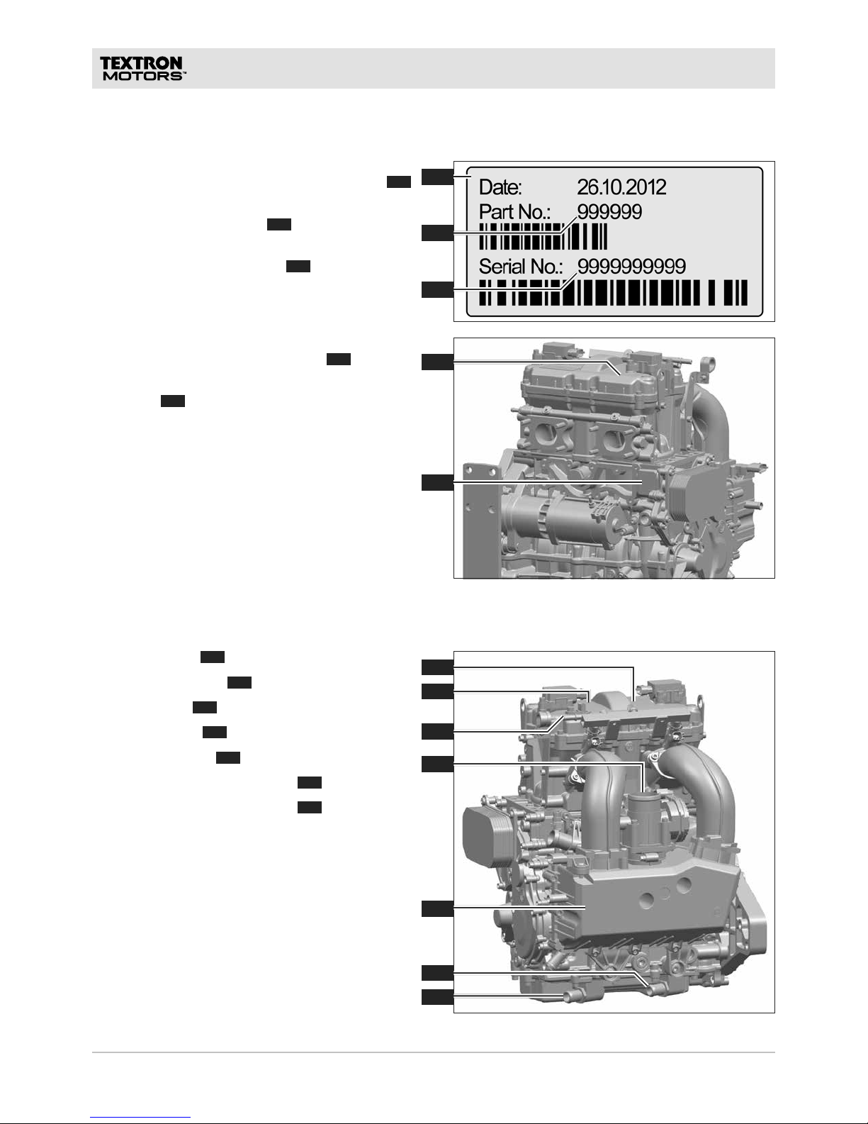
ENGINE IDENTIFIKATION
Each engine will be clearly identified by two
numbers. Both numbers are located on a label 1
on the engine.
The part number "Part No."
2
is the number of
the engine model.
The serial number "Serial No."
3
is an unique
number for each individual engine.
The label with the part number and the serial
number is located on the valve cover
4
.
The serial number is also engraved on the
crankcase
5
.
ENGINE COMPONENTS
– First cylinder
1
– Camshaft sensor 2 / Second cylinder
– Fuel supply
3
– Throttle body 4 / Air intake
– Intake manifold
5
/ Intake side
– Engine oil, oil tank to engine
6
– Engine oil, engine to oil tank
7
10 TD410023-B RLF
8
9
15
13
12
11
14
10
BEFORE YOU BEGIN WORKING
The intake manifold is not shown in the figure.
– Oil filter
8
– Coolant circuit to the heat exchanger
9
– Coolant circuit from the heat exchanger
10
– Permanent vent coolant circuit
11
– Exhaust ports 12 / Exhaust side
– Direction of engine rotation
13
– Power take off
14
– Crankcase vent / Engine oil return
15
11TD410023-B RLF
BEFORE YOU BEGIN WORKING
Visit WWW.TEXTRONOFFROAD.COM for more information.
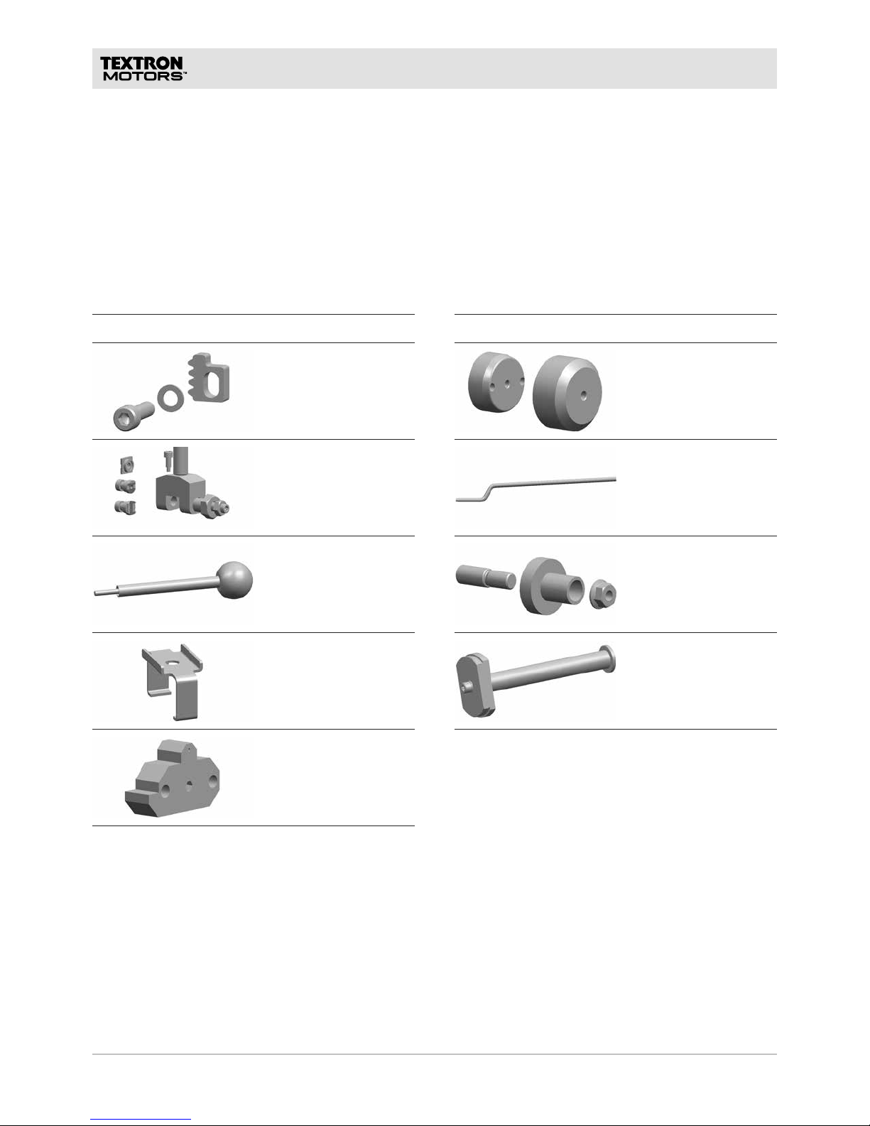
TEXTRON MOTORS SPECIAL TOOLS
Figure Description
Crankshaft locking tool
Chain tool
Valve stem seal
installation spike
Bearing cap remover
TDC-adjusting tool
Figure Description
Oil seal crankshaft
assembling kit
Intermediate gear axle
punch
Slide ring seal
assembling kit
Cylinder liner removal
tool
WORKSHOP EQUIPMENT
The tools and supplies described in this chapter you will require when working on the engine. Before you
begin working, check that all the tools required for the repair are available.
12 TD410023-B RLF
BEFORE YOU BEGIN WORKING
WORKSHOP EQUIPMENT AND TOOLS
In addition to the TEXTRON MOTORS special tools, you will require the following workshop equipment and
tools when working on the engine. The figures are examples of suitable workshop equipment and tools.
Figure Description
Workshop crane with
carrying strap
Minimum lifting capacy
300 kg [650 lb]
Engine stand
Minimum lifting capacy
300 kg [650 lb]
Mounting bolts M6 and
M10
Drain tray
Funnel
Syringe applicator
Minimum 40 ml
Bar magnet
Universal strap wrench
Rubber mallet
Figure Description
Torque wrench
3 – 70 Nm
[2 – 52 lbf ft]
with extension and
insert adapter
Reversible ratchet
with extension and
insert adapter
Torx® screwdriver and
inserts
T30
Hexagon screwdriver
and inserts
4, 5, 6, 7, 8 mm
Hexagon nut driver
and inserts
7, 10, 14 mm
Combination wrench
and inserts 7, 10, 12,
15, 19, 24, 27 mm
12-point socket
wrench
12 mm
Spark plug wrench
Wrench size 16 mm
[5/8“]
Diameter: maximum
22 mm [0.87 in]
13TD410023-B RLF
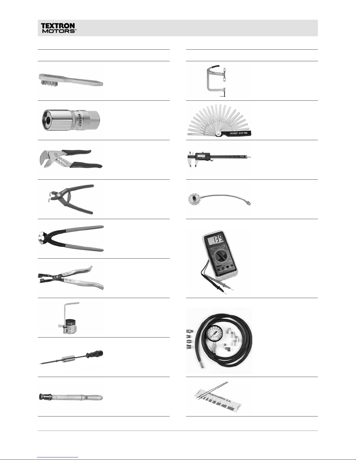
BEFORE YOU BEGIN WORKING
Figure Description
Spark plug brush
Stud extractor
8 mm
Universal pliers
Lockring pliers (bore
holes)
Clamping pliers
Valve stem seal
remover
Piston ring compressor
Oil seal slide hammer
Valve refacer
Figure Description
Valve spring
compressor
Feeler gauge
0,05 – 2 mm
Caliper
Measuring accuracy
0,05 mm
Angle indicator
Digital-multimeter
Oil pressure tester with
M10x1 adapter
Optional, for checking
the bearing clearances:
Precision clearance
gauges
0,025 mm – 0,04 mm

14 TD410023-B RLF
BEFORE YOU BEGIN WORKING
The following supplies you will require when working on the engine. Unless otherwise specified, use the
products as directed by the manufacturer.
SUPPLIES
Supplies Examples of suitable tools
Sealing surface cleaner
– Liqui Moly brake and parts cleaner AIII
Rust remover – WD-40
®
Multi-Use Product, WD-40 Company
Petroleum jelly for fitting o-rings and gaskets – Commercial petroleum jelly for industrial
applications
Lubricant for injector o-rings – Mobil DTE-24, DTE-25, DTE-26
– Exxon/Mobil Norpar 15
Silicone liquid seal – ThreeBond 1227E
– Dirko-S Profi Press HT
Anti-Seize assembly paste for lubricating threaded
connections
– WEICON
®
Anti-Seize "High-Tech" ASW 040 P
– LOCTITE® LB 8150
Thread locker, high strength – LOCTITE
®
272
Thread locker, medium strength – LOCTITE
®
243
Thread sealant – LOCTITE
®
542
– LOCTITE® 577
Valve grinding compound – TEROSON
®
valve grinding compound
Abrasive fleece – Scotch-Brite™ Superpads HP96 fine
– Scotch-Brite™ Handpads CF-HP very fine
– Scotch-Brite™ Handpads WR-HP very fine
Oil for generator interior – LIQUI MOLY Central hydraulic system oil 1127

15TD410023-B RLF
BEFORE YOU BEGIN WORKING
NOTES:

16 TD410023-B RLF
ENGINE DISASSEMBLYSECTION A – ENGINE DISASSEMBLY
NOTES:
A
17TD410023-B RLF
ENGINE DISASSEMBLY
Bearing damage, increased wear and leaks due to installing
components swapped over.
All components in and on the engine has been run-in together. If the
components are installed swapped over, they no longer fit together well.
► Keep your workspace clean and tidy.
► When you have removed parts, mark the cylinder assignment and
installation position.
► Ensure there is sufficient space available.
► Place the components in a way, that no confusion is possible.
► Install all components back into the same place where they were
removed.
Engine damage caused by small components in the engine or
cylinder head.
Operating the engine when there are small components in the crankcase
and cylinder head can result in serious damage and cause the crank drive
to seize.
► When removing small components, always cover the chain channel.
► Make sure that no small components remain in the engine.
Before you begin working, observe the following references:
– Observe that some engine components must be replaced after removal. These parts are marked
accordingly in the spare parts catalog and the work specifications will refer on it. Ensure that all required
spare parts are available.
– Before assembling components, clean all joint surfaces and sealing surfaces.
– If there is contamination in the lubrication system, cooling system or fuel unit, clean all components
concerned.
– When disposing of engine fluids, replaced parts or the whole engine, always comply with the relevant
applicable national laws and guidelines.
A
18 TD410023-B RLF
2
1
2
1
4
3
ENGINE DISASSEMBLY
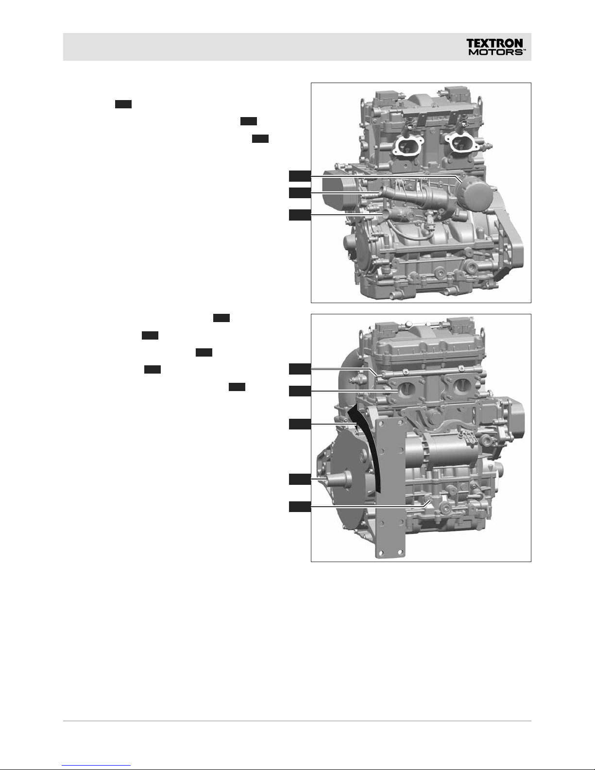
SECURING THE ENGINE
WARNING! Spinal column injury caused by
incorrect lifting of heavy loads. Always lift the
engine using a workshop crane.
NOTICE! Breakage. Lift the engine only using the
brackets.
Depending on the engine model, use the
brackets
1
and 2 or 3 and 4.
1. Lift the engine using the brackets until the
engine is mounted on the engine stand.
Observe the references in the chapters.
REMOVING ENGINE FROM THE VEHICLE
1. Remove the engine from the vehicle. (See the
vehicle manufacturer‘s documentation.)
1. Mount the engine across from the drive side on
the engine stand.
Suitable mounting points M10:
– Screw-in depth
1
and 2 30 mm
MOUNT THE ENGINE ACROSS FROM THE DRIVE SIDE
A
19TD410023-B RLF
B
B
B
A
B
B
B
B
B
B
B
A
1
1
2
A
ENGINE DISASSEMBLY
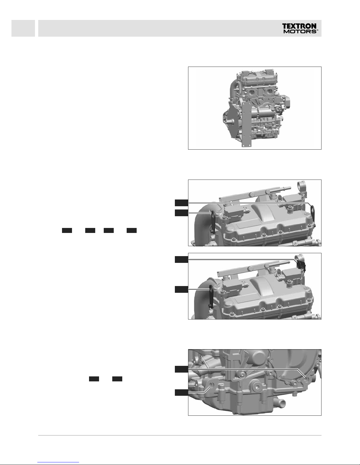
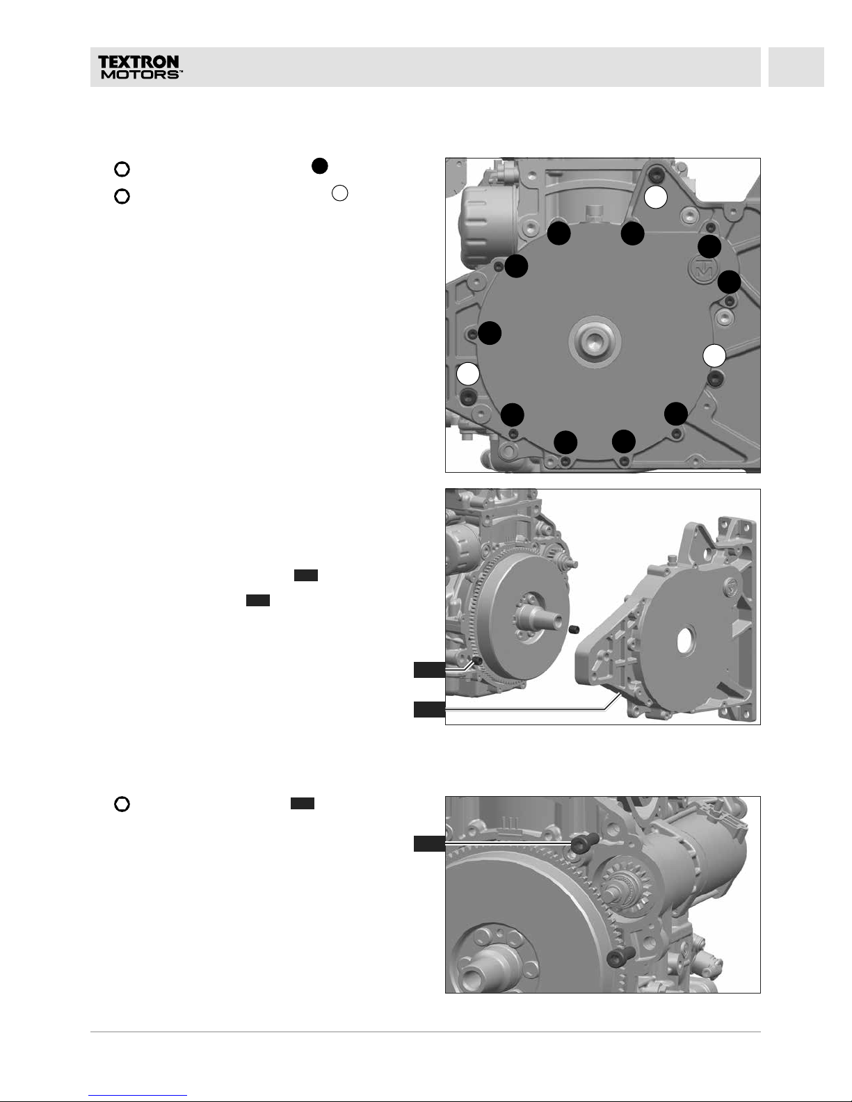
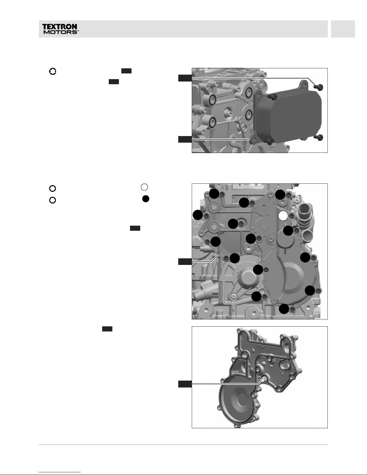
REMOVING GENERATOR COVER
1. 5 mm: Remove ten bolts M6 B.
2.
8 mm: Remove three bolts M10 A.
CAUTION! Danger of slipping caused by
leaking engine oil. Place a drain tray.
The generator cover is sealed with a silicone liquid
seal.
3. Remove the generator cover
2
.
4. Remove two sleeves
1
.
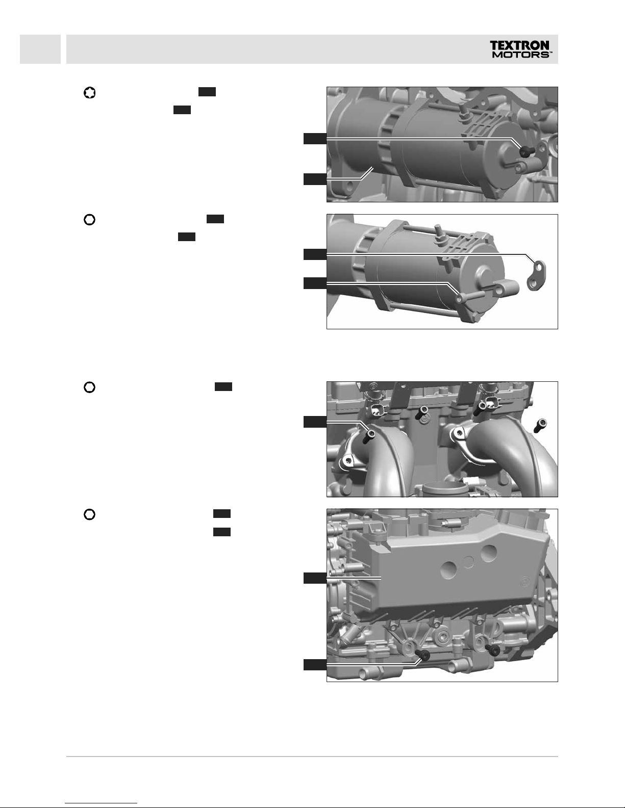
REMOVING STARTER
1. 8 mm: Remove two bolts 1.
A
20 TD410023-B RLF
2
5
1
2
3
3
4
ENGINE DISASSEMBLY
2. T30: Remove the bolt 2.
3. Remove the starter
3
.
4.
5 mm: Remove the bolt 5.
5. Remove the bracket
4
.
1.
5 mm: Remove four bolts 1.
REMOVING INTAKE MANIFOLD
2. 6 mm: Remove two bolts 3.
3. Remove the intake manifold
2
.
Observe in section C Additional working
instructions the chapters Intake manifold
disassembly and Intake manifold reassembly.
A
21TD410023-B RLF
1
2
1
2
1
2
ENGINE DISASSEMBLY
1. 5 mm: Remove eight bolts 1.
2. Remove the valve cover
2
.
Observe in section C Additional working
instructions the chapters Valve cover
disassembly and Valve cover reassembly.
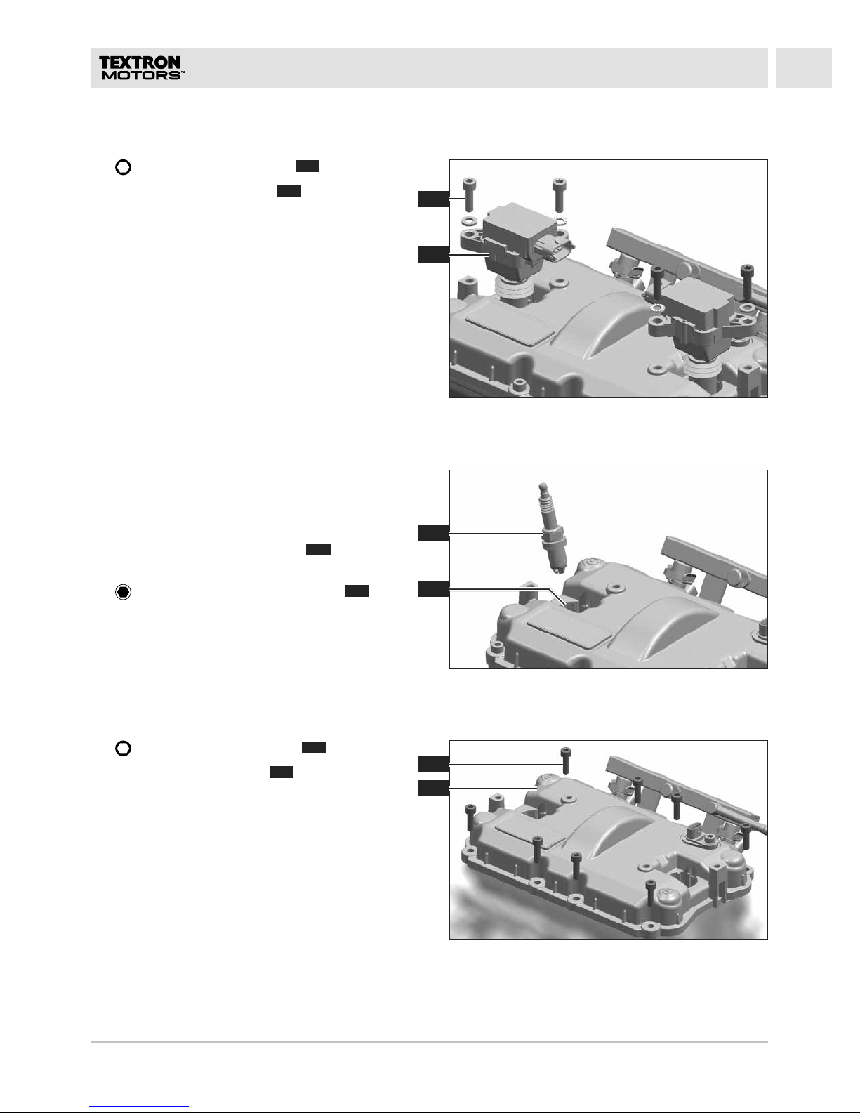
REMOVING VALVE COVER
1. 5 mm: Remove four bolts 1.
2. Remove two ignition coils
2
.
REMOVING IGNITION COILS
REMOVING SPARK PLUGS
WARNING! Irritations and eye injuries can be
caused by blown out dirt and particles. All
persons in the surrounding area must wear
protective glasses.
1. Blow out two spark plug bores
2
with
compressed air.
2.
16 mm: Screw in two spark plugs 1 using
a spark plug wrench.
A
22 TD410023-B RLF
1
2
4
2
3
4
1
3
ENGINE DISASSEMBLY
REMOVING ROCKER ARMS
Start with the cylinder where the rocker arms 1
have a certain amount of play.
1. Remove the rocker axle
2
using a universal
pliers.
2. Remove the rocker arm
3
.
3. Remove two valve adjustment shims
4
using
a bar magnet.
4. Repeat the procedure with the other rocker
arm.
5. Turn the crankshaft in the rotation direction
until the rocker arms on the other cylinder have
a certain amount of play.
6. Remove two rocker arms on the other cylinder.
1. Mount the engine on the drive side on the
engine stand.
Suitable mounting points M10:
– Screw-in depth
1
and 2 30 mm
Support:
– Minimum one mounting point M6
3
or 4.
MOUNT THE ENGINE ON THE DRIVE SIDE
A
23TD410023-B RLF
B
B
B
B
A
B
B
B
B
B
B
B
B
2
1
B
B
1
2
ENGINE DISASSEMBLY
REMOVING OIL COOLER BRACKET
1. 5 mm: Remove the bolt M6x30 A.
2.
5 mm: Remove 14 bolts M6x20 B.
CAUTION! Danger of slipping caused by
leaking coolant. Place a drain tray.
3. Remove the oil cooler bracket
1
.
4. Remove the sleeve
2
.
1.
T30: Remove four bolts 1.
2. Remove the oil cooler
2
.
REMOVING OIL COOLER
A

24 TD410023-B RLF
1
1
2
4
2
3
1
ENGINE DISASSEMBLY
REMOVING IMPELLER
1. Hold the crankshaft locking tool 1 on rotor in
position.
2.
8 mm: Install the bolt 2 and washer.
3.
10 mm: Remove the nut 4.
4. Remove the impeller
3
.
REMOVING SLIDE RING SEAL
1. 7 mm: Remove the water pump axle 1.
1.
T30: Remove the bolt 2.
2. Remove the cover
1
.
REMOVING CRANKSHAFT COVER
A
25TD410023-B RLF
1
2
1
3
1
2
2
4
ENGINE DISASSEMBLY
1. Mount the engine across from the drive side on
the engine stand.
Suitable mounting points M10:
– Screw-in depth
1
and 2 30 mm
MOUNT THE ENGINE ACROSS FROM THE DRIVE SIDE
REMOVING GENERATOR AND STUB SHAFT
1. 7 mm: Remove six bolts 1.
2.
8 mm: Remove the crankshaft locking
tool 2.
3. Remove the rotor
3
.
4. Remove the stub shaft
4
.
1.
4 mm: Remove the bolt 1.
2. Remove the sensor
2
.
REMOVING CRANKSHAFT SENSOR
A
26 TD410023-B RLF
7
8
5
6
1
4
3
5
6
2
ENGINE DISASSEMBLY
5. 5 mm: Remove four bolts 6.
6. Remove the stator
8
.
7. Remove the distance washer
7
.
8. Remove two sleeves
5
.
1. Remove the circlip
1
using a lockring pliers.
2. Remove the oil pump cover
2
using a
universal pliers.
REMOVING OIL PRESSURE PUMP
3. Remove the outer rotor 3 of the oil pressure
pump.
4. Remove the inner rotor
4
of the oil pressure
pump.
5. Remove the key
5
.
6. Remove the timing insert
6
.
A

27TD410023-B RLF
B
A
B
B B B
B
A
A
AA
B
A
A
2
1
4
1
2
3
4
3
ENGINE DISASSEMBLY
1. Turn the engine 180°.
2.
5 mm: Remove seven bolts M6x20 B and
seven bolts M6x30
A
.
REMOVING SUCTION PUMP COVER
The suction pump cover is sealed with a silicone
liquid seal.
3. Lift off the suction pump cover at the joints
1
and 2.
4. Remove the suction pump cover
3
.
5. Remove two sleeves
4
.
Observe in section C Additional working
instructions the chapters Suction pump cover
disassembly and Suction pump cover
reassembly.
MOUNT THE ENGINE ON THE DRIVE SIDE
1. Mount the engine on the drive side on the
engine stand.
Suitable mounting points M10:
– Screw-in depth
1
and 2 30 mm
Support:
– Minimum one mounting point M6
3
or 4.
A
28 TD410023-B RLF
1
4
2
3
2
1
ENGINE DISASSEMBLY
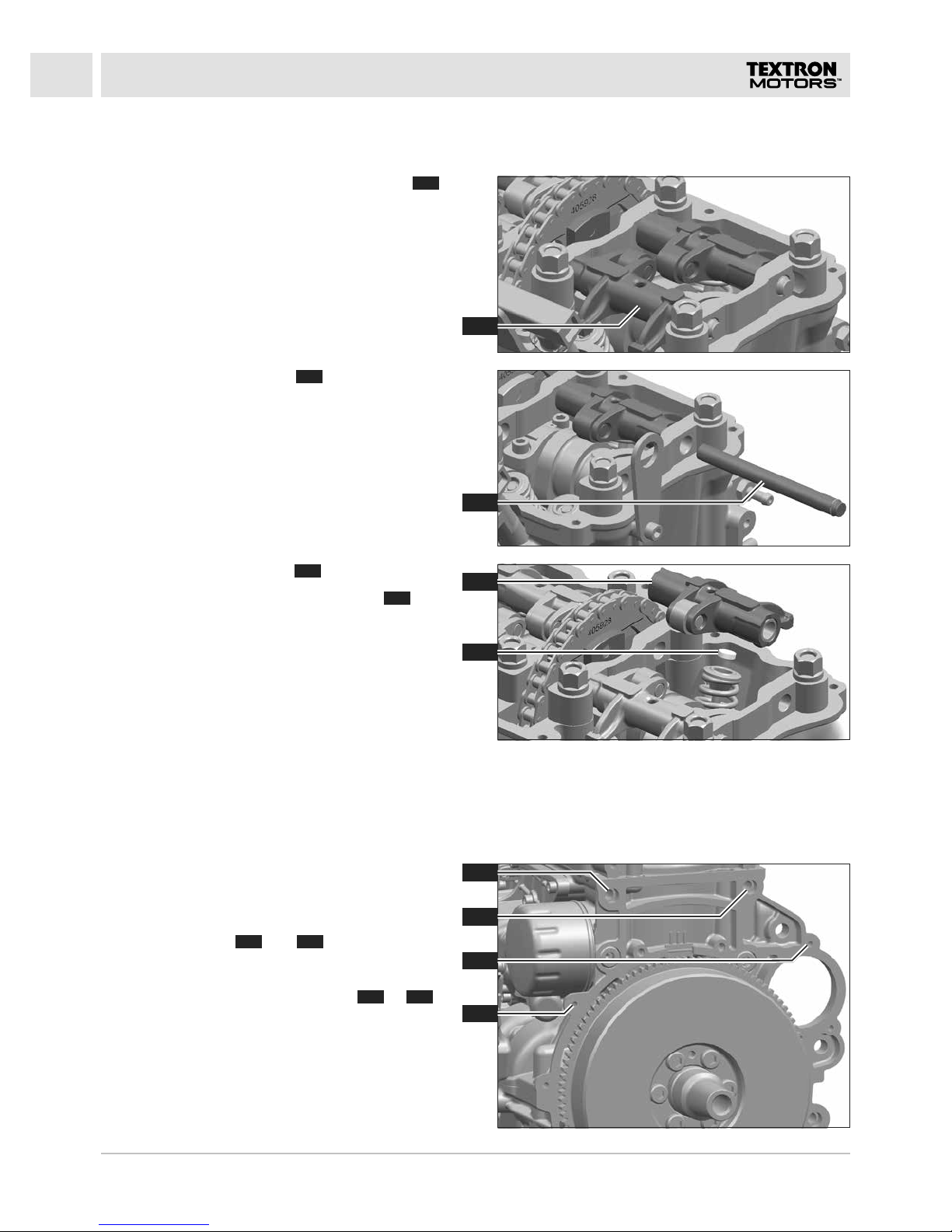
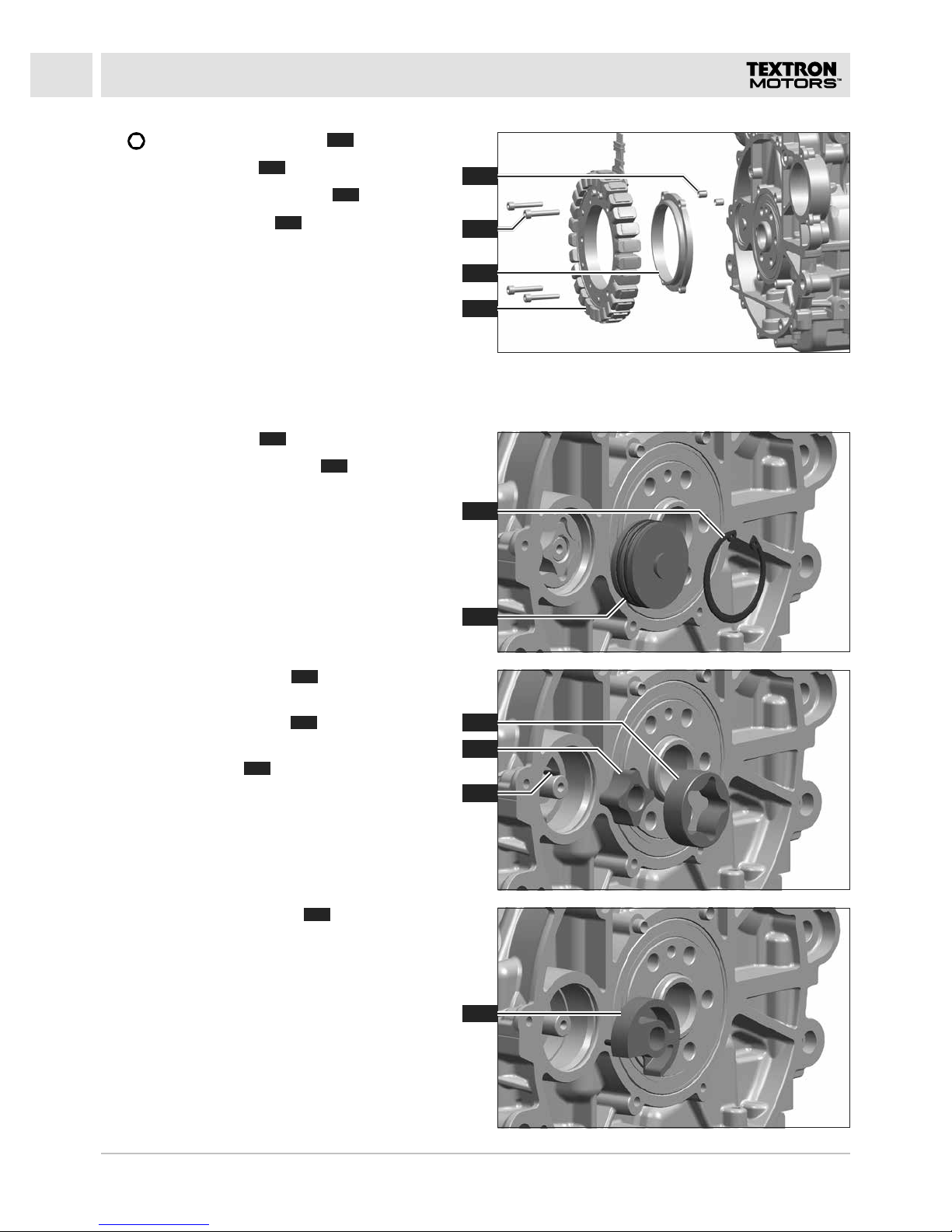
REMOVING SUCTION PUMP INTERMEDIATE GEAR
1. 8 mm: Remove the plug 1 and seal.
2. Knock out the axle
4
using the intermediate
gear axle punch 2 and plastic hammer.
3. Remove the suction pump intermediate
gear
3
.
4. Turn the engine 180°.
2. Mark the running direction of the timing
chain
2
.
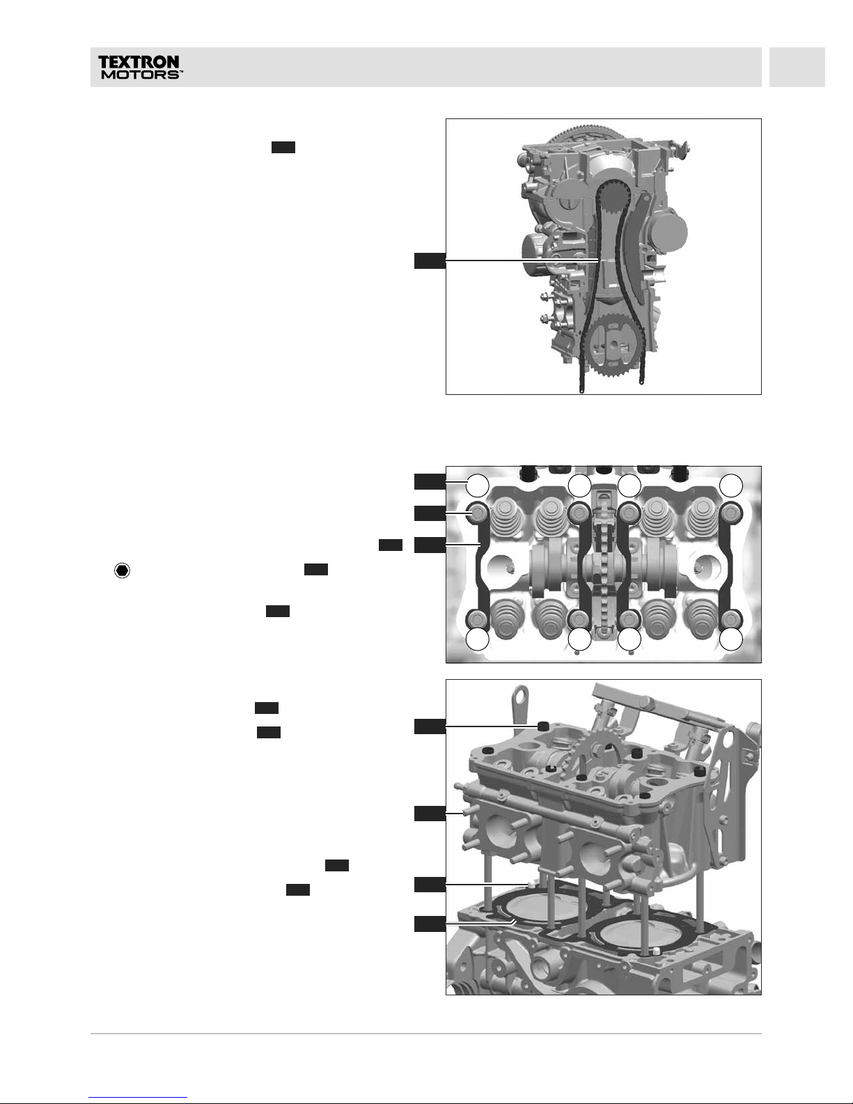
3. Open the timing chain using the chain tool.
(See the instruction manual of the chain tool.)
REMOVING TIMING CHAIN
1. 27 mm: Remove the chain tensioner 1.
A
29TD410023-B RLF
71 5 3
64 8 2
2
1
3
4
6
7
3
5
ENGINE DISASSEMBLY
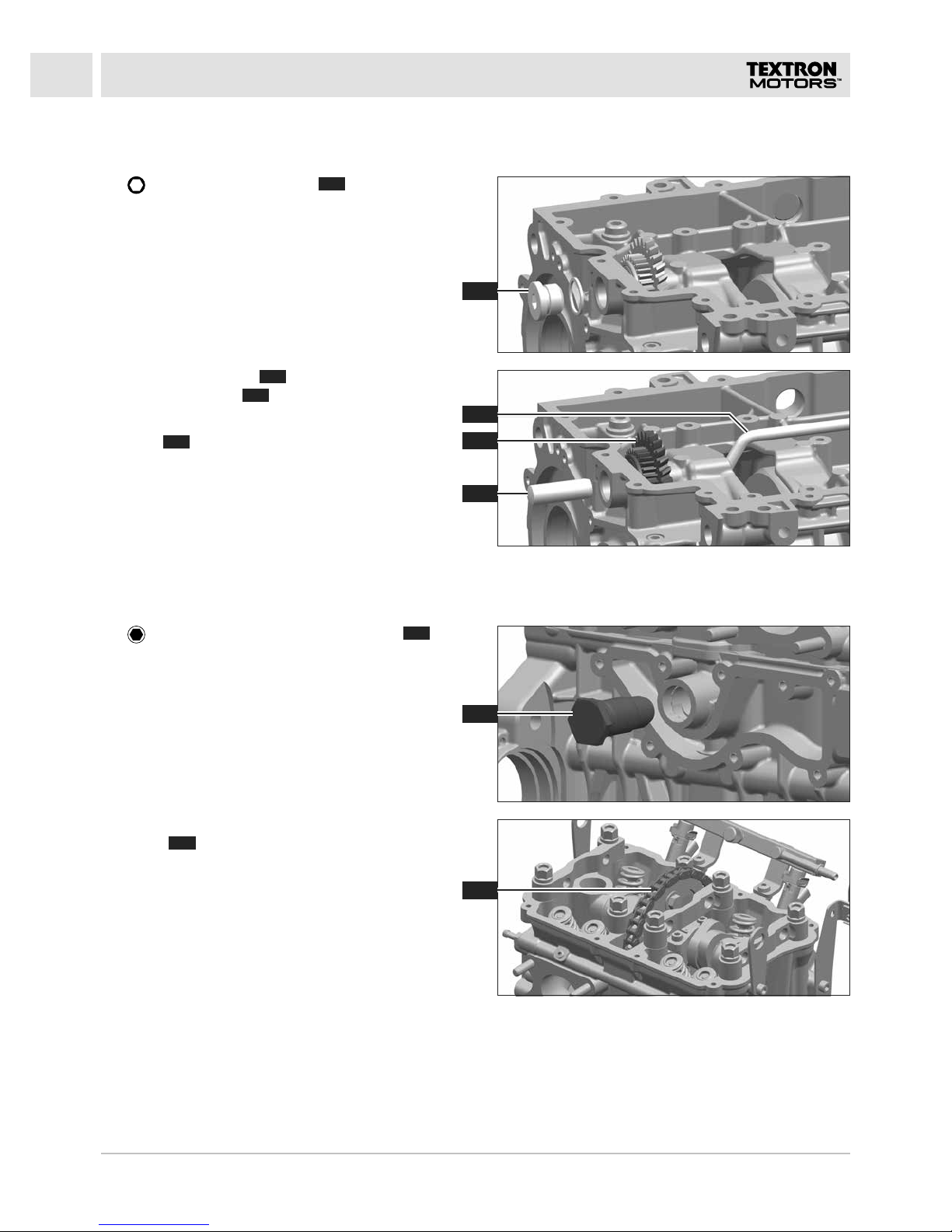
REMOVING CYLINDER HEAD
1. Check the tie rod thread protrusion according
to the specification Tie rod thread protrusion.
(See section D Test procedures and
adjustments.)
Remove all nuts in the sequence as illustrated
1
.
2.
14 mm: Remove eight nuts 2 and
washers.
3. Remove four cross bars
3
.
4. Remove the cylinder head.
5. Remove eight sleeves
4
.
6. When replacing a stud
5
, install the new stud
according to the specification M8 stud
cylinder head. (See section D Tightening
torques und assembly instructions.)
Observe in section C Additional working
instructions the chapters Cylinder head
disassembly and Cylinder head reassembly.
7. Remove the cylinder head gasket
7
.
8. Remove two centering pins
6
.
4. Turn the engine 180°.
5. Remove the timing chain
3
.
A
30 TD410023-B RLF
1
97 8
6
5
4
2
1
3
2
3
5
6
4
ENGINE DISASSEMBLY
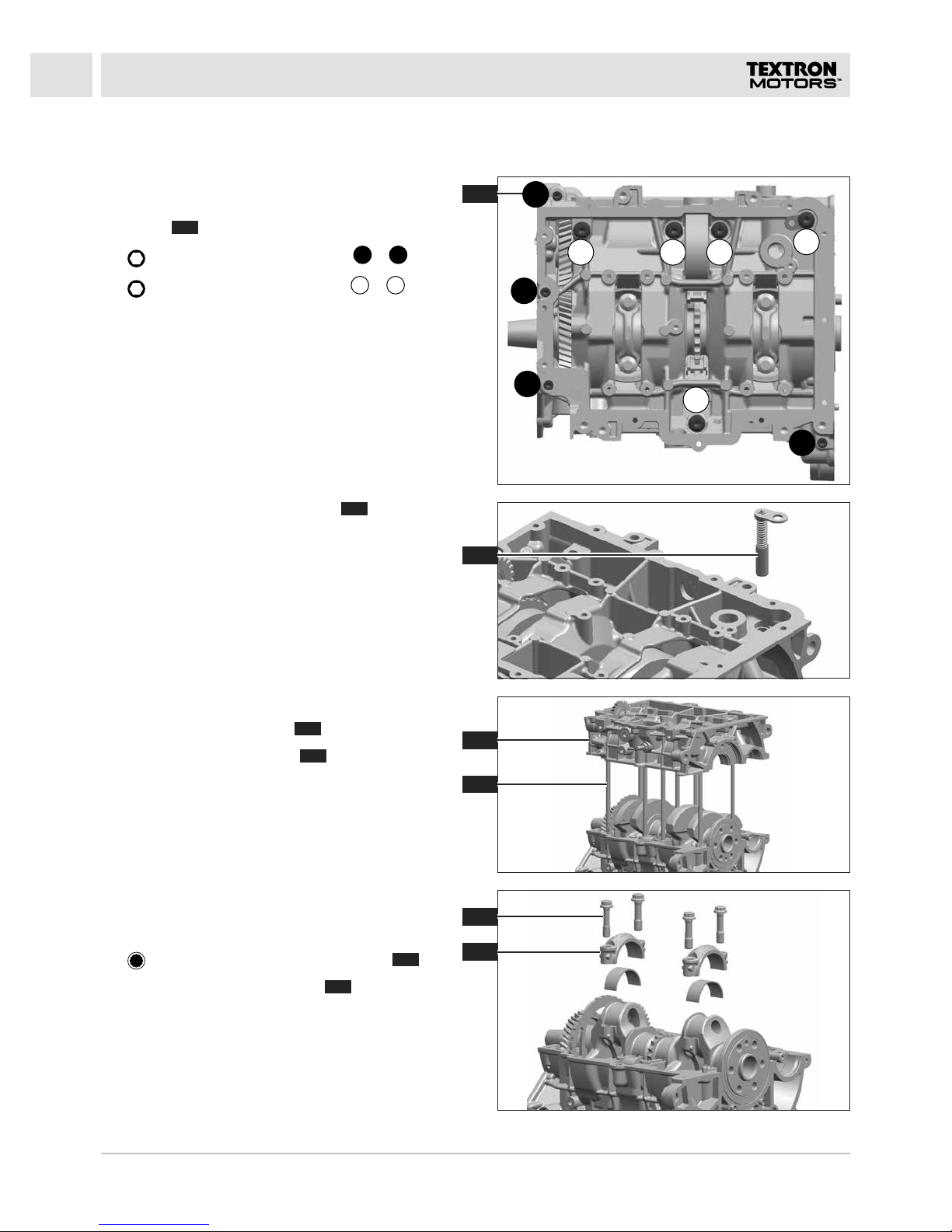
REMOVING CRANK DRIVE
1. Turn the engine 180°.
Remove all bolts in the sequence as
illustrated
1
.
2.
5 mm: Remove four bolts M6 1 – 4.
3.
6 mm: Remove five bolts M8 5 – 9.
4. Remove the oil pressure valve
2
using a bar
magnet.
The crankcase is sealed with a silicone liquid seal.
5. Remove the lower case 3.
6. When replacing a tie rod
4
, install the new
tie rod according to the specification Tie rods
M10x1.25. (See section D Tightening torques
und assembly instructions.)
Mark the cylinder assignment and installation
position on the piston, con rod, con rod cover and
bearing shells.
7.
12 mm: Remove four con rod bolts 5.
8. Remove two con rod covers
6
.
A
 Loading...