

Page 1
OPERATOR'S
MANUAL
Lycoming
0-235
AIRCRAFT ENGINES
4th Edition
Part No. 60297-9
and 0-290
Approved by F.A.A.
SERIES
January 1988
Page 2
LYCOMING OPERATOR'S MANUAL
ATTENTION
OWNERS, OPERATORS
MAINTENANCE PERSONNEL
This operator's manual contains a description of the engine, its
specifications, and detailed information on how to operate and maintain
Such maintenance procedures
it.
with periodic inspections are also included. This manual is intended for
use by owners, pilots and maintenance
Avco Lycoming powered aircraft.
are contained
nel should refer to these for such procedures.
Neglecting to follow
periodic
and power loss. Also, if power and speed limitations specified in this
manual are exceeded, for any reason, damage to the engine and personal
injury can happen.
ty.
SERVICE BULLETINS,
Although the information contained in this manual is up-to-date at
time of publication, users are
through Avco
ters which
factory by subscription.
L114 for subscription information.
in Avco Lycoming overhaul
SAFETY WARNING
the operating instructions
maintenance procedures
Consult your local FAA approved
Lycoming Service Bulletins,
are available from all Avco Lycoming
Consult the latest edition
that may be required in conjunction
Modifications and repair
can result in poor engine performance
INSTRUCTIONS
urged to keep abreast of later
AND
personnel responsible
manuals; maintenance person-
and to carry out
maintenance facili-
AND LETTERS
Instructions and Service Let-
distributors or from the
of Service Letter No.
for care of
procedures
information
SPECIAL NOTE
illustrations, pictures and drawings
The
typical of the subject matter they portray; in no instance are they to be
interpreted as examples of any specific engine, equipment or part
thereof.
shown in this publication
are
Page 3
TEXTRON LYCOMING OPERATOR'S MANUAL
IMPORTANT
Proper service
operation
by
operations. Some of
specially
and as recommended.
It is important
tain various Warnings
order to minimize the risk of
vice methods that may damage the engine or render it unsafe.
It is also important to
are
evaluate or advise
vice might be done
be involved.
satisfy themselves
ty will be
of all aircraft engines. The service
Textron Lycoming
designed for the task. These
not all inclusive. Textron
and repair is essential
are effective
these service operations require
to note that most Textron Lycoming
and Cautions which
understand that these Warnings
the service trade of all conceivable
or of the possible hazardous
Acordingly,
jeopardized
anyone who
thoroughly
by the service
SAFETY
personal injury or the use of
Lycoming could not possibly
that neither
NOTICE
to increase the safe, reliable
procedures recommended
methods
special tools must be used
uses a service
procedure
for performing
the use of tools
publications con-
must be carefully read in
improper ser-
and Cautions
ways in which ser-
consequences that may
procedure must
their safety
nor aircraft safe-
they select.
service
when
know,
first
Page 4

NEWAND REMANUFACTURED
(LIMITED)
RECIPROCATING AIRCRAFT ENGINE
WHAT TEXTRON
Textron Lycoming warrants each new and remanufactued reciprocating engine sold by it to be free from defects in
material and
acceptance testing The date of first operationmust not exceed two (2) years from the date ofshipment from Textron
Lycoming.
change basis, of the engine or any
in material or workmanship.
Lycomig will also bear the cost for labor in connection with the repair or replacement as provided in Textron
Lycoming's
the period
from the date of first operation, whichever occurs first, Textron Lycoming will reimburse you for a pro rata portion of the
charge for the repair or replacement (at its choice) with Textron Lycoming parts,ofparts required tobe repairedorre-
placed, or a replacement
during the proration period extends to major parts of the engine, which are limited to crankcase, crankshaft, camshaft,
cylinders, connecting rods, pistons, sump, accessory housing and gears. The proration policy does not extend to labor or
to accessories, including but not limited to magnetos, caburetors or fuel injectors, fuel pumps, sarers, alternators and
turbochargers and their controllers.
Lycoming distributor within 30 days of the appearance of the defect in material or workmanship.
the part of Textron Lycoming set forth above are your exclusive remedy and the exclusive liability of Textron Lycoming.
This warranty allocates the risk of product failure between you and Textron Lycoming, as permitted by applicable law.
been subject to accident or used, adjusted, altered,
manual, or if non-genuine Textron Lycoming parts are installed in or on the engine and are determined tobeapossible
cause of the incident for which the warranty application is filed.
such alterations in engines or parts previously sold.
workmanship appearing within one (1) year from
Textron Lycoming's
In addition, if Textron Lycoming determines
until the expiration of Textron Lycoming's recommended
Any engine or
The
engine must have
Textron Lycoming's warranty does
Textron Lycoming
Textron Lycoming may change the
obligation under this warranty shall be limited
part of the engine, when Textron Lycoming has determined
Such repair or replacement will be made
then current Removal and
part so repaired or
reserves the right
Installation Labor Allowance Guidebook.
engine, if it determines that engine replacement
replaced will be
received normal
not cover normal maintenance expenses or consumable
construction of engines at any time without incurring
LYCOMING PROMISES
the date of first operation, excluding necessary aircraft
to its choice of repair or replacement, on anex-
by Textron Lycoming at no charge to you. Textron
that the engine proves to be defective in material
entitled to warranty
OBLIGATIONS
YOUR
use and service.
to deny any warranty claim
handled, maintained or stored other than as directed
Time Between Overhaul (TBO), or
is required. Textron Lycoming's obligation
for the remainder
You must apply
for warranty
if it reasonably determines
YOU
that the engine is defective
or workmanship during
two (2) years
of the original
with an authorized
any obligation to incorporate
waranty period.
Textron
items. The obligations on
that the engine or part
in your operator's
has
Page 5
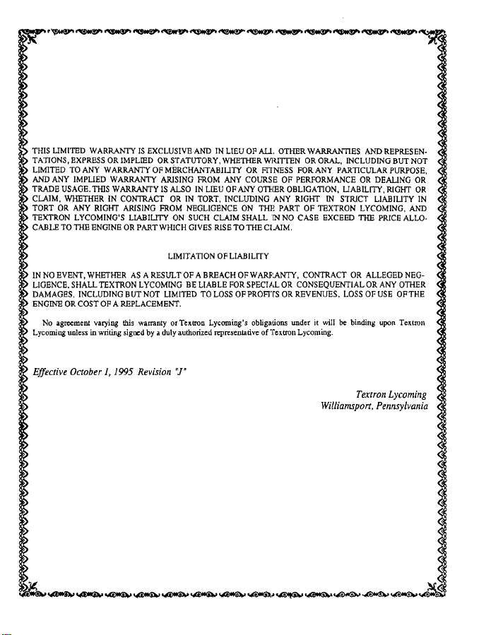
THIS LIMITED
TATIONS,
LIMITED TO ANY WARRANTY OF MERCHANTABILITY
AND ANY IMPLIED WARRANTY
TRADE USAGE. THIS
CLAIM, WHETHER IN CONTRACT OR IN TORT, INCLUDING ANY RIGHT IN STRICT LIABILITY IN
TORT
TEXTRON LYCOMING'S LIABILITY ON
CABLE TO THE ENGINE
WARRANTY IS EXCLUSIVE AND IN LIEU
EXPRESS OR IMPLIED OR STATUTORY,
WARRANTY IS ALSO IN LIEU OF ANY OTHER
OR ANY RIGHT ARISING FROM NEGLIGENCE
ARISING FROM ANY COURSE OF PERFORMANCE
OR PART WHICH GIVES RISE
WHETHER WRITTEN OR ORAL, INCLUDING
SUCH CLAIM SHALL NNO CASE EXCEED
OF ALL. OTHER WARRANTIES AND REPRESEN-
OR FITNESS FOR ANY PARTICULAR
OBLIGATION, LIABILITY, RIGHT OR
ON THE PART OF TEXTRON LYCOMING,
TO THE CLAIM.
BUT NOT
PURPOSE,
OR DEALING OR
THE PRICE ALLO-
AND
LIMITATION
IN NO EVENT, WHETHER
LIGENCE, SHALL TEXTRON LYCOMING
DAMAGES, INCLUDING BUTNOT LIMITED TOLOSSOF PROFITSOR REVENUES, LOSS OF USE OF THE
ENGINE OR COST OF A
No agreement varying
Lycoming unless in writing signed by a duly authorized representative of Textron Lycoming.
Effective October
AS A RESULT OF A BREACH OF WARRANTY,
REPLACEMENT.
this warranty or Textron Lycoming's obligations
1, 1995 Revision
"J'
OF LIABILITY
BE LIABLE FOR SPECIAL OR CONSEQUENTIAL
CONTRACT OR ALLEGED NEG-
under it will be binding upon Textron
Textron
Williamsport, Pennsylvania
OR ANY OTHER
Lycoming
Page 6
WARRANTY
REPLACEMENT
Textron Lycoming
inmaterial and
must not exceed
tion.
Textron
basis, of te
change
workmanship.
ment as provided
part so repaired
Any
The engine
warranty
workmanship.
Textron
part of Textron
the
This warranty
Textron
been subject to
manual, or if non-genuine
cause of the
Textron
such alterations
THIS LIMITED
TATIONS,
LIMITED
AND ANY
USAGE.
TRADE
CLAIM,
OR ANY
TORT
TEXTRON
CABLE TO THE
warrants each
workmanship appearing
two (2) years from
Lycoming's obligation
replacement part,
Lycoming will
Textron
in Textron Lycoming's
in which
with an authorized
Lycoming's
Lycoming
the risk of
allocates
Lycoming reserves
accident or used,
incident for
may change the
Lycoming
engines or
in
WARRANTY
OR IMPLIED
EXPRESS
ANY WARRANTY
TO
WARRANTY
IMPLIED
THIS WARRANTY
WHETHER
IN CONTRACT
RIGHT ARISING
LYCOMING'S
ENGINE OR PART
PART -RECIPROCATING
(LIMITED)
WHAT TEXTRON
new reciprocating aircraft
under this
when TextronLycoming
also reimburse you
will be warranted
or replaced
the replacement
Textron Lycoming
does not cover
warranty
which the warranty
above are your
set forth
product failure
the right
adjusted, altered,
Textron Lycoming parts are installed
construction of
pars previously
IS EXCLUSIVE
OR STATUTORY,
OF MERCHANTABILITY
ARISING
IS ALSO IN
FROM
LIABILITY
WHICH GIVES
LYCOMING
one (I) year from
within
the date of shipment
warranty shall
then current Removal
for the remainder
OBLIGATIONS
YOUR
part is installed
distributor
normal maintenance
exclusive
between
any warranty
to deny
handled, minained
application
engines at any time
sold.
AND IN
FROM
LIEU OF ANY
OR IN TORT,
NEGLIGENCE
CLAIM
ON SUCH
AIRCRAFT
PROMISES
engine replacement pat
from Textron
be limited to its
has
for the costs
and Installation
have received
must
within 30 days
remedy and
you and Textron
claim if it reasonably
in or on the engine and are determined to be a possible
is filed.
LIEU OF
WHETHER
OR FITNESS
ANY COURSE
INCLUDING
ON
SHALL
RISE TO THE
first operation. The
its date of
Lycoming.
choice of repair
determined that
for labor in connection
Labor Allowance Guidebook
original warranty
of the
normal use
of the appearance
consumable
expenses or
the exclusive
Lycoming,
or stored other
without incurring
ALL OTHER
OTHER
THE PART
OR
WRITTEN
FOR
OF PERFORMANCE
OBLIGATION,
RIGHT IN
ANY
OF TEXTRON
IN NO CASE
CLAIM.
ENGINE
YOU
sold by it to be free from
or replacement,
the pan is defective
with the repair
period.
and service.
of the defect in
items. The obligations
liability of Textron
as permitted
that
determines
than as directed
any obligation
WARRANTIES
ORAL, INCLUDING
ANY PARTICULAR
LIABILITY,
STRICT
EXCEED
date of first opera-
on an ex-
in material or
or replace-
apply for
You must
material or
Lycoming.
by applicable
or part has
the engine
in your operator's
to incorporate
REPRESEN-
AND
BUT NOT
PURPOSE,
OR DEALING
RIGHT
LIABILITY
LYCOMING,
PRICE
THE
defects
law.
OR
OR
AND
ALLO-
on
IN
Page 7
IN
NO
EVENT,
LIGENCE,
DAMAGES,
ENGINE
OR COST
No agreement
Lycoming
Effective
WHETHER
SHALL
TEXTRON
INCLUDING
OF A REPLACEMENT.
varying
unless in
writing
October
AS ARESULT
BUT
this warranty
signed
1, 1995
LIMITATION
LYCOMING
NOT LIMITED
or
Textron
by a duly
authorized
Revision
"J"
OF
OF A BREACH
BE LIABLE
TO LOSS
Lycoming's
representative
LIABILITY
OF WARRANTY,
FOR
SPECIAL
OF
PROFTS
obligations
of
Textron
CONTRACT
OR
CONSEQUENTIAL
OR
REVENUES,
under
it will
Lycoming.
Williamsport,
OR ALLEGED
OR
LOSS
OF USE
be binding
Textron
Pennsylvania
NEG-
ANY OTHER
OF THE
upon
Textron
Lycoming
Page 8
I
. Lycoming
WARRANTY
(LIMITED)
RECIPROCATING
OVERHAULED
AIRCRAFT
ENGINE
WHAT TEXTRON
Textron Lycoming warrants
workmanship appearing
testing.
The date of first
Textron Lycoming's
change basis, of the
in material or
Lycoming
will also bear the cost
Lycoming's
Any engine
The engine
Lycoming distributor
Textron
Lycoming's
the pan ofTextron
This
warranty allocates the
Textron Lycoming reserves
been subject to accident
manual,
or if non-genuine
cause of the
Textron Lycoming
such alterations
THIS LIMITED
TATIONS, EXPRESS
LIMITED TO
AND ANY
TRADE
USAGE. THIS
CLAIM, WHETHER
TORT
OR ANY RIGHT
TEXTRON LYCOMING'S
CABLE TO THE
within one (1) year
obligation under
engine or any part of the
workrmanship. Such repair
then current Removal and
or part so repaired
must have received
within
warranty does
Lycoming set forth
or used, adjusted,
incident for which
may change
in engines or
WARRANTY IS
OR IMPLIED
ANY WARRANTY OF
IMPLIED WARRANTY
WARRANTY
IN CONTRACT
ENGINE OR
each overhauled
operation must
or replaced will
reciprocating engine sold
from the date of first
not exceed two
thi:; warranty shall be limited
engine, when Textron Lycoming
or replacement will be made
for labor in connection
Installation Labor Allowance Guidebook.
be entitled to warranty
YOUR
normal
30 days of
risk of product failure between
Textron Lycoming
parts previously sold.
ARISING
LIABILITY
use and service.
the appearance
not cover nominal
abovt are your exclusive
the right to deny any
altered, handled, maintained
the warranty
PART WHICH GIVES
parts are installed
rpplication
the construction
EXCLUSIVE AND IN
OR STATUTORY,
MERCHANTABILITY
ARISING FROM
IS ALSO IN
O IN TORT, INCLUDING
FROM NEGLIGENCE
ON SUCH CLAIM SHALL
of engines at any
LYCOMING PROMISES
by it to be free from defects
operation, excluding necessary
(2) years from the
date of shipment
to its choice of repair
has determined
by Textron Lycoming
with the repair or
for the remainder
replacement as provided
OBLIGATIONS
You must apply
of the defect
maintenance
you and Textron Lycoming,
warranty claim if it reasonably
is filed.
LIEU OF ALL OTHER
WHETHER
ANY COURSE OF PERFORMANCE
LIEU OF ANY
ON THE
RISE TO
for warranty with
in material
or workmanship.
expenses or consumable
remedy and the exclusive
determines that
or stored other than as
in or on the
engine and are
time without incurring
WRITTEN
OR FITNESS FOR ANY
OTHER OBLIGATION,
THE CLAIM.
WARRANTIES AND REPRESEN-
OR ORAL, INCLUDING
ANY RIGHT
PART OF TEXTRON
IN NO CASE EXCEED
YOU
in material and
aircraft acceptance
from Textron
at no charge to you. Textron
of the original
liability of Textron Lycoming.
as permitted by
determined to be
any obligation
PARTICULAR PURPOSE,
IN STRICT LIABILITY
Lycoming.
or replacement, on
that the engine is defective
in Textron
warranty
an authorized
items. The
obligations on
applicable law.
the engine or part has
directed in your operator's
to incorporate
OR DEALING
LIABILITY,
RIGHT OR
LYCOMING,
THE PRICE ALLO-
an ex-
period.
Textron
a possible
BUT
NOT <
OR
AND
<
IN
Page 9
I
IN
NO EVENT,
LIGENCE,
DAMAGES,
ENGINE
OR
No
agreement
Lycoming
Effective
WHETHER
SHALL
INCLUDING
COST
unless
in
October
TEXTRON
OF
A
varying
writing
1, 1995
AS
A RESULT
LYCOMING
BUT
NOT
signed
warranty
by a
LIMITED
or
duly
REPLACEMENT.
this
Revision
LIMITATION
OF
A BREACH
BE LIABLE
TO
LOSS
Textron
Lycoming's
authorized
representative
J"
OF
LIABILITY
OF
WARRANTY,
FOR
SPECIAL
OF PROFITS
obligations
OR
OR
of Textron
CONTRACT
CONSEQUENTIAL
REVENUES,
under
Lycoming.
it will
LOSS
be
Williamsport,
OR
ALLEGED
OR
OF
binding
Textron Lycoming
NEG-
ANY
OTHER
USE OF
THE
upon
Textron
Pennsylvania
i
i
Page 10
LYCOMING
TABLE OF CONTENTS
OPERATOR'S
MANUAL
Page
SECTION 1
SECTION 2
SECTION 3
SECTION 4
SECTION 5
SECTION 6
SECTION 7
SECTION 8
DESCRIPTION
SPECIFICATIONS
OPERATING INSTRUCTIONS
PERIODIC INSPECTIONS
MAINTENANCE PROCEDURES
TROUBLE-SHOOTING
INSTALLATION AND STORAGE
TABLES
1-1
2-1
3-1
4-1
5-1
6-1
7-1
8-1
Page 11
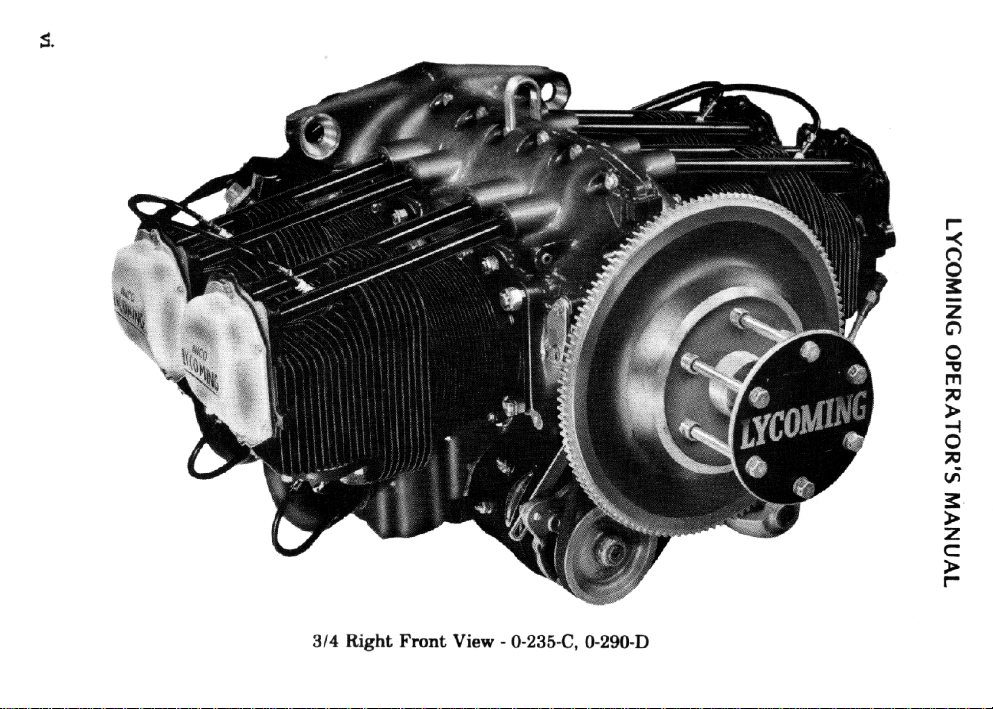
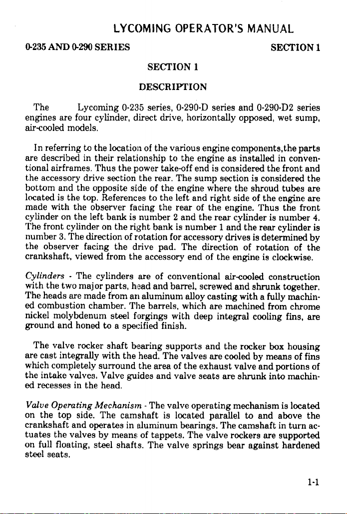
5.
314 Right Fmnt View - 0-235-C, 0-290-D
Page 12
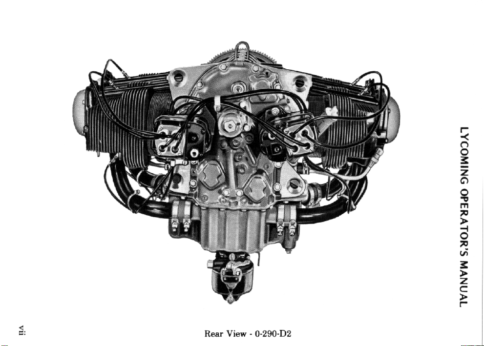
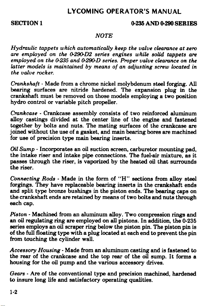
Rear View - O-290-D2
Page 13
LYCOMING
DESCRIPTION
General ................................................ 1-1
Cylinders .............................................. 1-1
Valve Operating
Crankshaft ............................................
Crankcase .............................................
Oil Sum p .............................................. 1-2
Connecting Rods ...................................... 1-2
P isto n s . ... .. .... .. ... ... . ... .. .. .. . .... .. .. .... ... .... 1-2
Accessory Housing ..................................... 1-2
Gears ................................................. 1-2
Cooling System ........................................ 1-3
Lubricating System ..................................... 1-3
Induction System ....................................... 1-3
Ignition System
Table of M odels ........................................ 1-4
M echanism .............................
........................................
OPERATOR'S
MANUAL
Page
1-1
1-2
1-2
1-3
Page 14
LYCOMING
OPERATOR'S
MANUAL
0-235 AND
The
engines
air-cooled
In referring
are described
tional airframes.
the
accessory
bottom
located
made with
cylinder
The front
number
the
crankshaft,
Cylinders
with the
The
ed combustion
nickel
ground
0-290 SERIES
Lycoming
are four cylinder,
models.
to
in their
drive
and
the
is the top.
the observer
on the
cylinder
3. The
observer
heads
molybdenum
viewed
- The
two
are made
and
honed to
direction
facing
major
0-235 series,
the location
relationship
Thus
the power
section
opposite
References
left bank
on
the right
of rotation
the
from the
cylinders
parts,
from
chamber.
steel
a specified
SECTION 1
DESCRIPTION
direct drive,
of the various
to
take-off
the rear.
side of
the engine
to the left
facing
the rear
is
number
drive
are
head
an aluminum
The
forgings
2 and the
bank
for
pad. The
accessory
of conventional
and
barrel,
barrels,
with
finish.
0-290-D
the engine
The
is number
which
series
and 0-290-D2
horizontally opposed,
engine
components,the
as installed
end is considered
sump section
where
and right
of the
accessory
direction
end
screwed
alloy casting
deep integral
engine. Thus
rear
1 and
drives
of the
engine
air-cooled
are
machined
the
side of
cylinder
the rear
of rotation
and
with
SECTION
series
wet sump,
in conven-
the front and
is
considered
shroud
tubes
the engine
the
is number
cylinder
is determined
is clockwise.
shrunk
a fully
cooling
of
construction
together.
machin-
from
chrome
fins, are
1
parts
the
are
are
front
4.
is
by
the
The
valve
are cast
which
the
intake
ed
recesses
Valve Operating
on the
crankshaft
tuates
on full
steel
seats.
rocker
integrally
completely
valves,
in the
top side.
and operates
the valves
floating,
shaft bearing
with the
surround
Valve
guides and
head.
Mechanism
The
camshaft
in aluminum
by means
steel
shafts.
supports
head. The
the
area of
-The valve
is
of tappets.
The
valve springs
valves
the exhaust
valve
seats
operating
located
bearings.
The valve
and
the rocker
are
cooled by
valve
are shrunk
mechanism
parallel
The camshaft
rockers
bear against
box
means
and
into
to and
are supported
housing
of fins
portions
machin-
is located
above
in
turn ac-
hardened
of
the
1-1
Page 15
LYCOMING
OPERATOR'S
MANUAL
SECTION
Hydraulic
are employed
employed
latter
the valve rocker.
Crankshaft -Made from
bearing
crankshaft must
hydro
Crankcase
alloy castings
together by bolts
joined
for use
Oil Sump -
the intake
passes through
the riser.
Connecting
forgings. They
and
the crankshaft
each cap.
1
tappets which
on the
on the 0-235
models is
surfaces are
control or variable
without the
of precision
split type bronze
maintained by
be removed
- Crankcase
divided at
and nuts.
use of a gasket,
Incorporates an
riser and
the riser,
Rods - Made in the
have replaceable
ends are retained by means of
type main
intake pipe connections.
bushings in
0-235 AND 0-290
NOTE
automatically keep
0-290-D2 series
and 0-290D series.
means of an adjusting
a chrome nickel molybdenum
nitride hardened.
on those models
pitch propeller.
assembly consists
the center line
The mating surfaces
and main bearing
bearing
oil suction screen,
is vaporized
form of "H" sections from alloy
bearing
the piston ends.
the valve clearance
engines while
Proper valve
The expansion
employing a
of two reinforced
of the engine
inserts.
carburetor
The
by the heated
inserts in the
two bolts and nuts through
SERIES
solid tappets
clearance on
screw
located in
steel forging. All
plug
two position
aluminum
and fastened
of the crankcase
bores are
fuel-air mixture,
oil that surrounds
The bearing caps
machined
mounting pad,
crankshaft ends
at zero
are
the
in the
are
as it
steel
on
Piston
- Machined
an oil
regulating ring
series employs
of the
full floating
from touching
Accessory Housing -
the rear of
housing for
Gears - Are of to insure
an oil scraper
type with
the cylinder
the crankcase and the top
the oil pump
the conventional
long life
and satisfactory
from an aluminum
are employed
ring below the
a plug
wall.
Made from an aluminum casting
and the various
alloy. Two
on all pistons.
located at
type and precision
operating
piston pin. The
each end to
rear of the oil sump. It forms
accessory
qualities.
compression
In addition, the
piston pin is
prevent
and is fastened to
drives.
machined,
rings and
0-235
the pin
a
hardened
Page 16
LYCOMING OPERATOR'S MANUAL
0-235 AND 0-290 SERIES SECTION 1
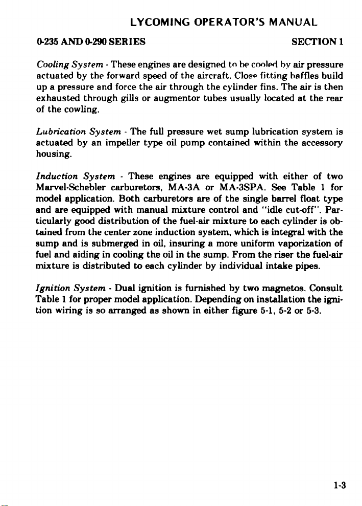
Cooling
actuated by the forward
up
exhausted through gills or augmentor tubes usually located at the rear
of the cowling.
Lubrication System -The full
actuated by an impeller type oil pump contained within the accessory
housing.
Induction System - These engines are equipped with either of two
Marvel-Schebler carburetors, MA-3A or MA-3SPA. See Table 1 for
model
and are equipped with
ticularly
tained from
sump and is submerged in oil, insuring a more uniform vaporization of
fuel and aiding in cooling the
mixture is distributed to
Ignition
Table
tion
System -These engines are
speed of the aircraft. Close
a pressure and force the air through
application. Both carburetors
manual mixture control and
good distribution of the fuel-air
the center zone induction system,
each cylinder by individual
System - Dual ignition is
1 for proper model application.
wiring is so arranged as shown
designed to be cooled by air
pressure wet sump lubrication
oil in the sump. From the riser
furnished by two magnetos.
Depending on installation
in either figure 5-1, 5-2
pressure
fitting baffles build
the cylinder fins. The air
system is
are of the single barrel float
"idle cut-off". Par-
mixture to each cylinder is
which is integral with the
the fuel-air
intake pipes.
Consult
the igni-
or 5-3.
is then
type
ob-
Page 17
LYCOMING
OPERATOR'S
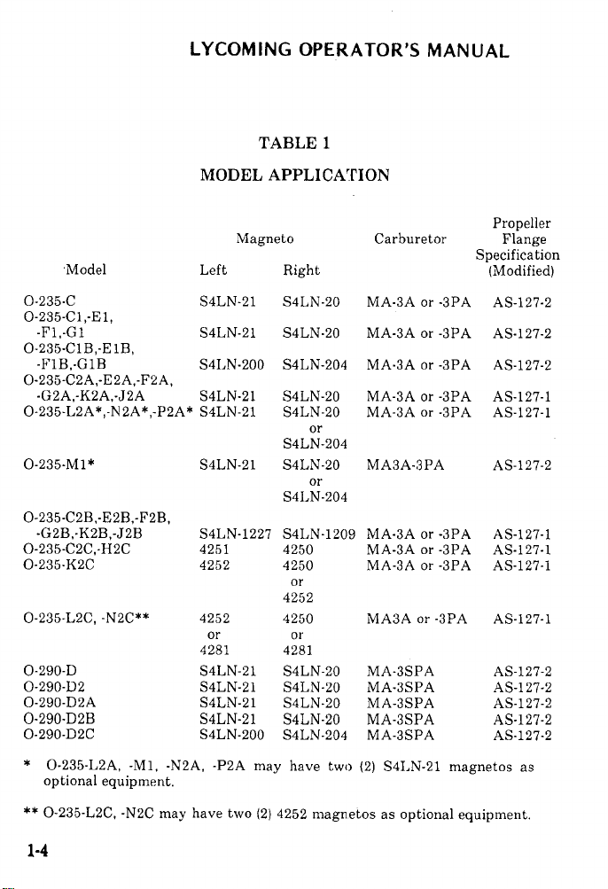
TABLE 1
MODEL APPLICATION
MANUAL
Model
0-235-C
0-235-C,-E1,
-F1,-G1
0-235-C1B,-E1B,
-F1B,-G1B
0-235-C2A,-E2A,-F2A,
-G2A,-K2A,-J2A
0-235-L2A*,-N2A*,-P2A*
0-235-M1*
0-235-C2B,-E2B,-F2B,
-G2B,-K2B,-J2B
0-235-C2C,-H2C
0-235-K2C
0-235-L2C, -N2C**
0-290-D
0-290-D2
0-290-D2A
0-290-D2B
0-290-D2C
* 0-235-L2A,
optional
-M1, -N2A, -P2A
equipment.
Magneto
Left
S4LN-21 S4LN-20
S4LN-21
S4LN-200 S4LN-204
S4LN-21 S4LN-20
S4LN-21 S4LN-20
S4LN-21
S4LN-1227
4251
4252
4252
or
4281
S4LN-21
S4LN-21
S4LN-21
S4LN-21
S4LN-200
Right
S4LN-20
or
S4LN-204
S4LN-20
or
S4LN-204
S4LN-1209
4250
4250
or
4252
4250
or
4281
S4LN-20
S4LN-20
S4LN-20
S4LN-20
S4LN-204
may have two
Carburetor Flange
MA-3A
MA-3A
MA-3A
MA-3A
MA-3A or -3PA AS-127-1
MA3A-3PA
MA-3A or -3PA
MA-3A or -3PA
MA-3A or -3PA
MA3A or -3PA
MA-3SPA
MA-3SPA
MA-3SPA
MA-3SPA
MA-3SPA
(2) S4LN-21
or -3PA AS-127-2
or -3PA
or -3PA
or -3PA
Propeller
Specification
(Modified)
AS-127-2
AS-127-2
AS-127-1
AS-127-2
AS-127-1
AS-127-1
AS-127-1
AS-127-1
AS-127-2
AS-127-2
AS-127-2
AS-127-2
AS-127-2
magnetos as
** 0-235-L2C,
1-4
-N2C may have
two (2) 4252
magnetos as optional
equipment.
Page 18
LYCOMING
SPECIFICATIONS
Specifications -0-235 ................................... 2-1
Specifications - 0-290 ................................... 2-2
Accessory Drives ...................................... 2-2
Alternate Power Ratings ..... .......................... 2-3
Detail Weights ........................................ 2-4
OPERATOR'S
MANUAL
Page
Page 19
LYCOMING
OPERATOR'S
MANUAL
SECTION 2 0-235 AND 0-290 SERIES
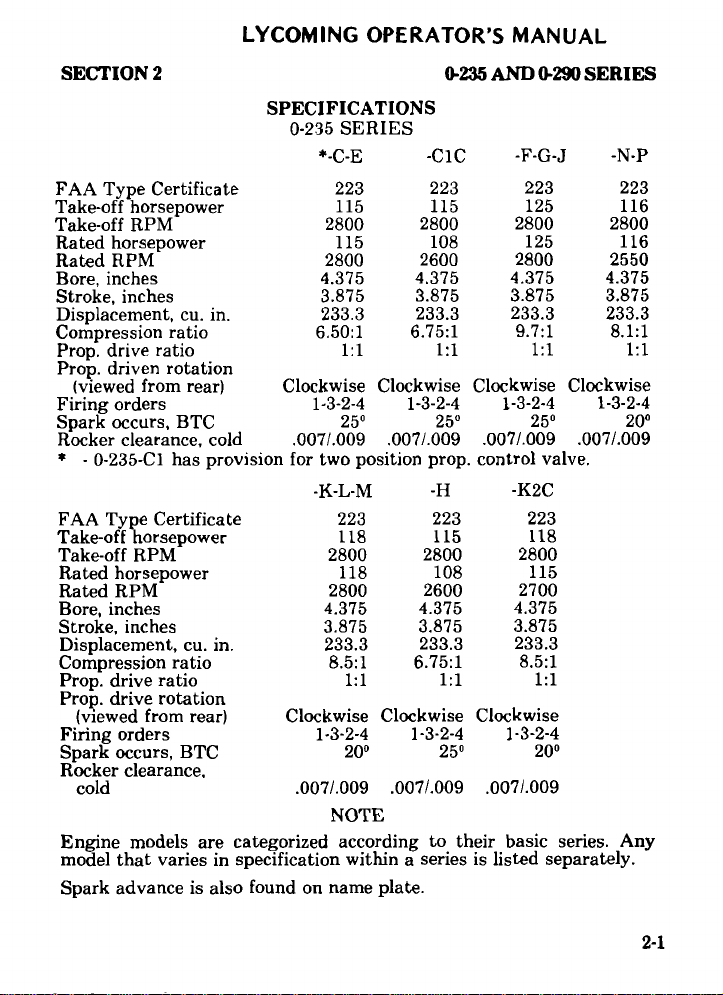
SPECIFICATIONS
0-235 SERIES
*-C-E -C1C -F-G-J -N-P
FAA Type Certificate
Take-off horsepower
Take-off
RPM
Rated horsepower
Rated RPM
Bore, inches
Stroke, inches
Displacement,
cu. in.
223
115
2800 2800
115
2800
4.375 4.375
3.875
233.3 233.3
223
115
108
2600
3.875
Compression ratio 6.50:1 6.75:1
Prop. drive
ratio
1:1 1:1
223
125
2800
125
2800
4.375
3.875
233.3
9.7:1
1:1
223
116
2800
116
2550
4.375
3.875
233.3
8.1:1
Prop. driven rotation
(viewed
Firing
Spark
Rocker clearance,
* - 0-235-C1
from rear)
orders
occurs, BTC
cold .007/.009
has provision
FAA Type Certificate
Take-off
horsepower
Take-off RPM
horsepower
Rated
Rated RPM
Bore, inches
Stroke, inches
Displacement, cu. in.
Compression ratio
Prop. drive ratio
Clockwise Clockwise
1-3-2-4
25
1-3-2-4
25
.007/.009
for two position prop.
-K-L-M
223
118
2800
118
2800
4.375
3.875
233.3
8.5:1
1:1
-H -K2C
223
115
2800
108
2600
4.375
3.875
233.3
6.75:1
1:1
Clockwise
1-3-2-4 1-3-2-4
.007/.009 .007/.009
control valve.
Clockwise
25 20
223
118
2800
115
2700
4.375
3.875
233.3
8.5:1
1:1
Prop. drive rotation
20
Clockwise
1-3-2-4
25
Clockwise
1-3-2-4
20
.007/.009
(viewed from rear)
orders
Firing
Spark occurs, BTC
Rocker
clearance.
cold
Clockwise
1-3-2-4
.007/.009 .007/.009
NOTE
Engine
models
model that varies
Spark
advance
is also
are categorized
according to
in specification within a
found on
name plate.
their basic series.
series is listed separately.
Any
1:1
2-1
Page 20
0-235
AND 0-290
LYCOMING
SERIES
OPERATOR'S
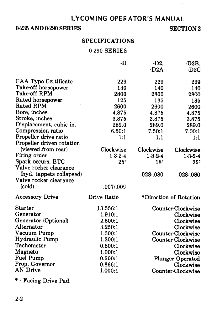
SPECIFICATIONS
0-290
SERIES
MANUAL
SECTION
2
FAA
Type
Take-off
Take-off
Rated
Rated RPM
Bore,
Stroke,
Displacement,
Compression
Propeller
Propeller
(viewed
Firing
Spark
Valve
(hyd.
Valve
(cold)
Accessory
Starter
Generator
Generator
Alternator
Vacuum
Hydraulic
Tachometer
Magneto
Fuel Pump
Prop.
AN
Drive
* -
Facing
Certificate
horsepower
RPM
horsepower
inches
inches
drive ratio
driven
from
order
occurs,
rocker
tappets
rocker
Drive
(Optional)
Pump
Pump
Governor
Drive
cubic
ratio
rotation
rear)
BTC
clearance
collapsed)
clearance
Pad.
in.
Drive
13.556:1
229
130
2800
125
2600
4.875
3.875
289.0
6.50:1
1:1
Clockwise
1-3-2-4
25
.007/.009
Ratio
1.910:1
2.500:1
3.250:1
1.300:1
1.300:1
0.500:1
1.000:1
0.500:1
0.866:1
1.000:1
-D2,
-D2A
229
140
2800
135
2600
4.875
3.875
289.0
7.50:1
1:1
Clockwise
1-3-2-4
18
.028-.080
*Direction
Counter-Clockwise
Counter-Clockwise
Counter-Clockwise
Plunger
Counter-Clockwise
-D2B,
-D2C
229
140
2800
135
2600
4.875
3.875
289.0
7.00:1
1:1
Clockwise
1-3-2-4
25
.028-.080
of Rotation
Clockwise
Clockwise
Clockwise
Clockwise
Clockwise
Operated
Clockwise
2-2
Page 21
LYCOMING
OPERATOR'S
MANUAL
SECTION
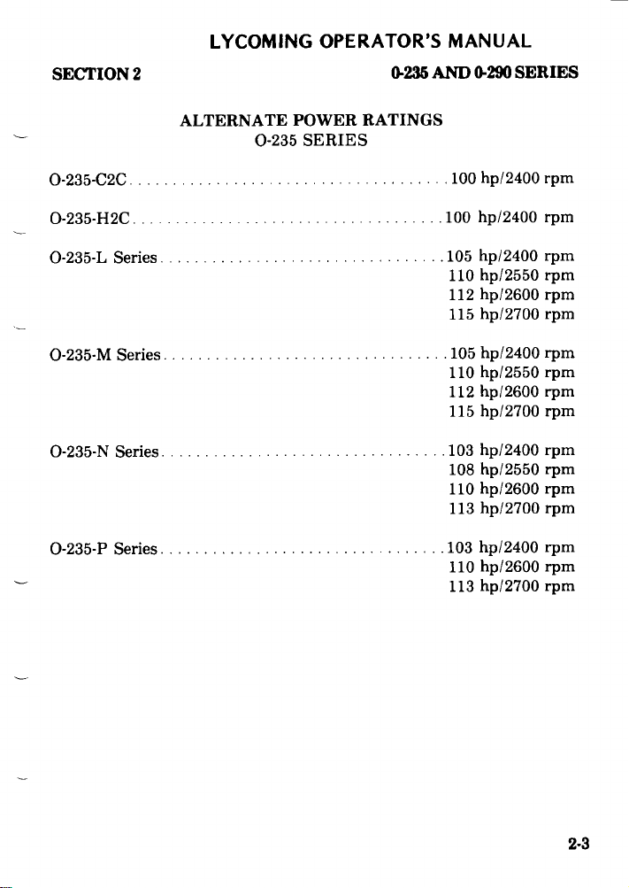
0-235-C2C
0-235-H2C
0-235-L
0-235-M
0-235-N
0-235-P
Series
Series
Series
Series
2
ALTERNATE
0-235
.....................................
.........................
................................
...........................
...........................
.................................
0-235
POWER RATINGS
SERIES
.........
AND 0-290
100
100
SERIES
hp/2400
hp/2400
105 hp/2400
110 hp/2550
112 hp/2600
hp/2700
115
hp/2400
105
110 hp/2550
112 hp/2600
115 hp/2700 rpm
103 hp/2400
hp/2550
108
hp/2600
110
hp/2700
113
hp/2400
103
110 hp/2600
hp/2700
113
rpm
rpm
rpm
rpm
rpm
rpm
rpm
rpm
rpm
rpm
rpm
rpm
rpm
rpm
rpm
rpm
2-3
Page 22
LYCOMING
OPERATOR'S
MANUAL
SECTION 2
DETAIL
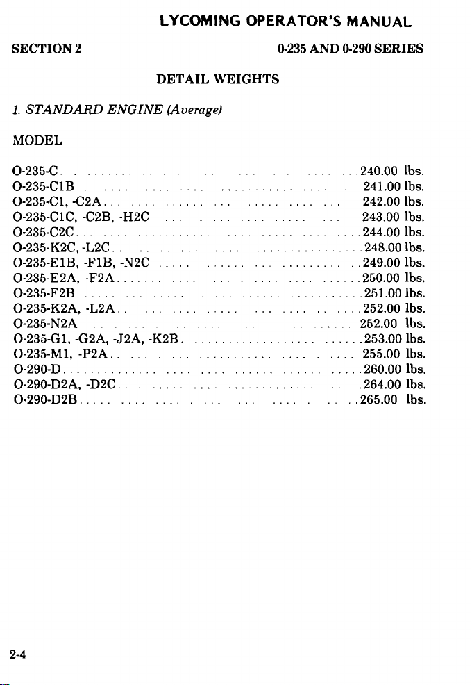
1. STANDARD ENGINE (Average)
MODEL
0-235-C. ......... ... .. ... .... ... 240.00 lbs.
0-235-C1B... .... ....................... ... 241.00 lbs.
0-235-C1, -C2A ...
0-235-C1C, -C2B, -H2C ... .......... ... 243.00 lbs.
O-235-C2C .. ................. ......... ..... 244.00 lbs.
O-235-K2C, -L2C .... ............................ 248.00 Lbs.
O-235-E B, -F1B, -N2C ..... .................. .. 249.00 lbs.
O-235-E2A, -F2A ....... ...... ......... ...... 250.00 lbs.
O-235-F2B . . ..... ..... ...... ........... 251.00 lbs.
O-235-K2A, -L2A .. ..................... .... 252.00 lbs.
O-235-N2A. ..................... 252.00 lbs.
0-235-G1, -G2A, -J2A, -K2B. ........................ 253.00 lbs.
0-235-M1, -P2A .................. ..... 255.00 lbs.
0-290-D ........................... ...... ...... 260.00 lbs.
O-290-D2A, -D2C .............................. .. 264.00 lbs.
0-290-D2B ............. ......... ..... 265.00 lbs.
............... ......
WEIGHTS
0-235 AND 0-290 SERIES
. 242.00 lbs.
2-4
Page 23
LYCOMING
OPERATOR'S
MANUAL
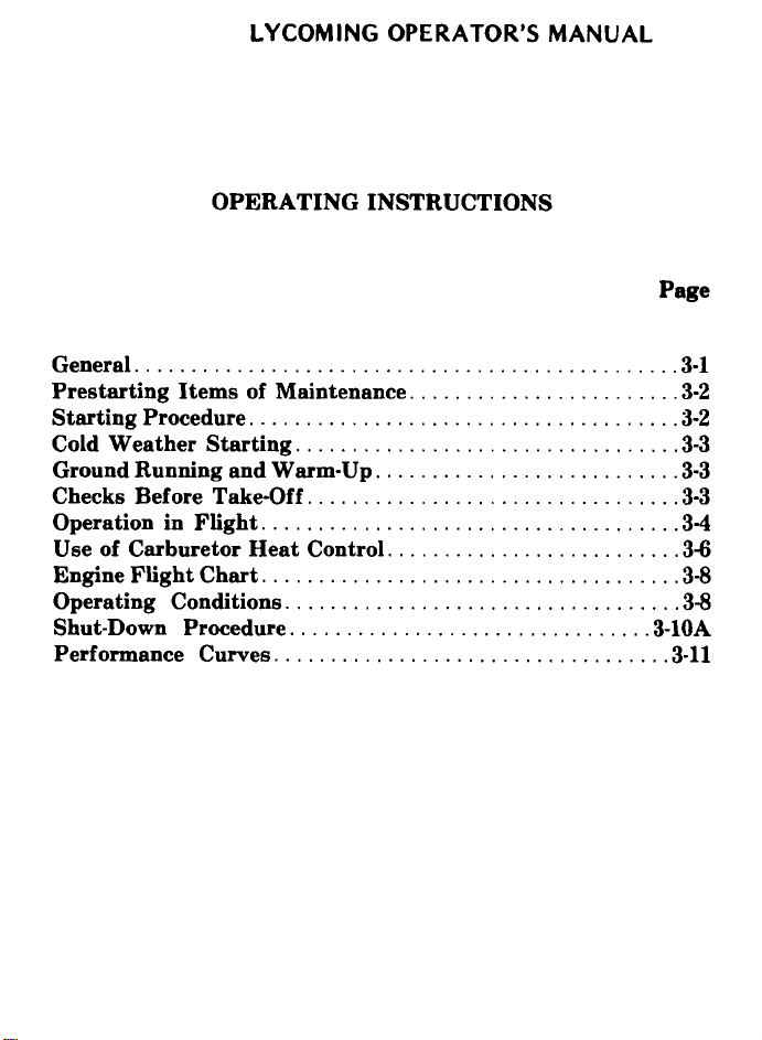
OPERATING
General ...................... ......................... 3-1
Prestarting Items of Maintenance ........................ 3-2
Starting Procedure .................... .................. 3-2
Cold W eather
Ground Running and
Checks Before Take-Off
Operation in Flight
Use of Carburetor Heat Control .......................... 3-6
Engine
Operating
Shut-Down Procedure
Performance Curves ............................
Flight Chart ....................
Starting ..................................
Warm-Up ...........................
.....................................
Conditions ..................................
................................
INSTRUCTIONS
.................................
.................
Page
3-3
3-3
3-3
3-4
3-8
3-8
3-10A
.. 3-11
Page 24
LYCOMING
0-235 AND 0-290 SERIES SECTION 3
OPERATOR'S
SECTION 3
MANUAL
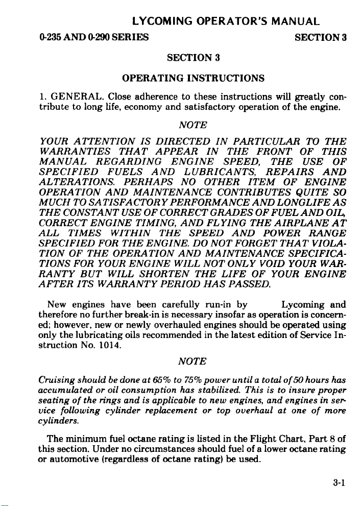
OPERATING
1. GENERAL. tribute to long life, economy and satisfactory operation of the engine.
YOUR ATTENTION IS DIRECTED IN PARTICULAR TO THE
WARRANTIES THAT APPEAR IN THE FRONT OF THIS
MANUAL REGARDING
SPECIFIED
ALTERATIONS. PERHAPS NO OTHER ITEM OF ENGINE
OPERATION AND MAINTENANCE CONTRIBUTES QUITE SO
MUCH TO SATISFACTORY
THE CONSTANT USE
CORRECT ENGINE TIMING,
ALL TIMES WITHIN THE SPEED AND POWER RANGE
SPECIFIED FOR THE ENGINE. DO NOT FORGET THAT VIOLA-
TION OF
TIONS FOR YOUR
RANTY BUT WILL SHORTEN THE LIFE OF YOUR ENGINE
AFTER ITS WARRANTY PERIOD HAS PASSED.
New engines
therefore no further break-in is necessary insofar as operation is concern-
ed; however, new or newly overhauled engines should be operated using
only the lubricating oils recommended in the latest edition of Service In-
struction
Close adherence to these
FUELS AND
OF CORRECT GRADES OF
THE OPERATION AND MAINTENANCE
ENGINE WILL NOT ONLY
have been carefully run-in
No. 1014.
INSTRUCTIONS
instructions will greatly con-
NOTE
ENGINE SPEED, THE
LUBRICANTS, REPAIRS
PERFORMANCE
AND FLYING THE AIRPLANE
NOTE
AND LONGLIFE AS
FUEL AND OIL
SPECIFICA-
VOID YOUR WAR-
by Lycoming and
USE OF
AND
AT
Cruising should be done at 65% to 75% power until a total of 50 hours has
accumulated or oil consumption
seating of the rings and is applicable to new engines, and engines in ser-
vice following cylinder replacement or top overhaul at one of more
cylinders.
The minimum fuel octane rating is listed in the Flight Chart, Part 8 of
this section. Under no circumstances should fuel of a lower octane rating
or automotive (regardless of octane rating) be used.
has stabilized. This is to
insure proper
3-1
Page 25
LYCOMING OPERATOR'S
SECTION 3 0-235 AND 0-290 SERIES
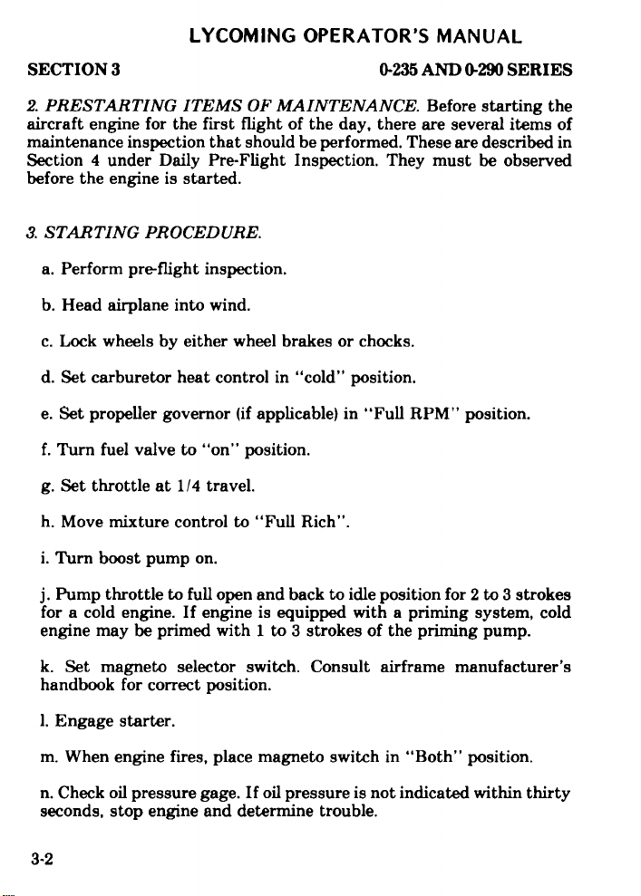
2. PRESTARTING ITEMS OF MAINTENANCE. Before starting the
aircraft engine for the first
maintenance inspection
Section 4 under Daily
before the
3. STARTING PROCEDURE.
a. Perform pre-flight inspection.
b. Head airplane into wind.
c. Lock wheels by either wheel brakes or chocks.
d. Set carburetor heat control in "cold" position.
engine is started.
flight of the day, there are several
that should be performed.
Pre-Flight Inspection. They
MANUAL
items of
These are described in
must be observed
e. Set propeller governor
f. Turn fuel valve to "on" position.
g. Set throttle at 1/4 travel.
h. Move mixture control to "Full Rich".
i. Turn boost pump on.
j. Pump throttle to full open
for a cold engine. If engine is equipped with a priming system, cold
engine may
k. Set magneto selector switch. Consult airframe manufacturer's
handbook for correct position.
1. Engage starter.
m. When engine fires, place magneto switch in "Both" position.
n. Check oil pressure gage. If oil pressure is not indicated within thirty
seconds, stop engine and determine trouble.
3-2
be primed with 1 to 3
(if applicable) in "Full RPM"
and back to idle position for
strokes of the priming pump.
position.
2 to 3 strokes
Page 26
LYCOMING
OPERATOR'S
MANUAL
0-235 AND
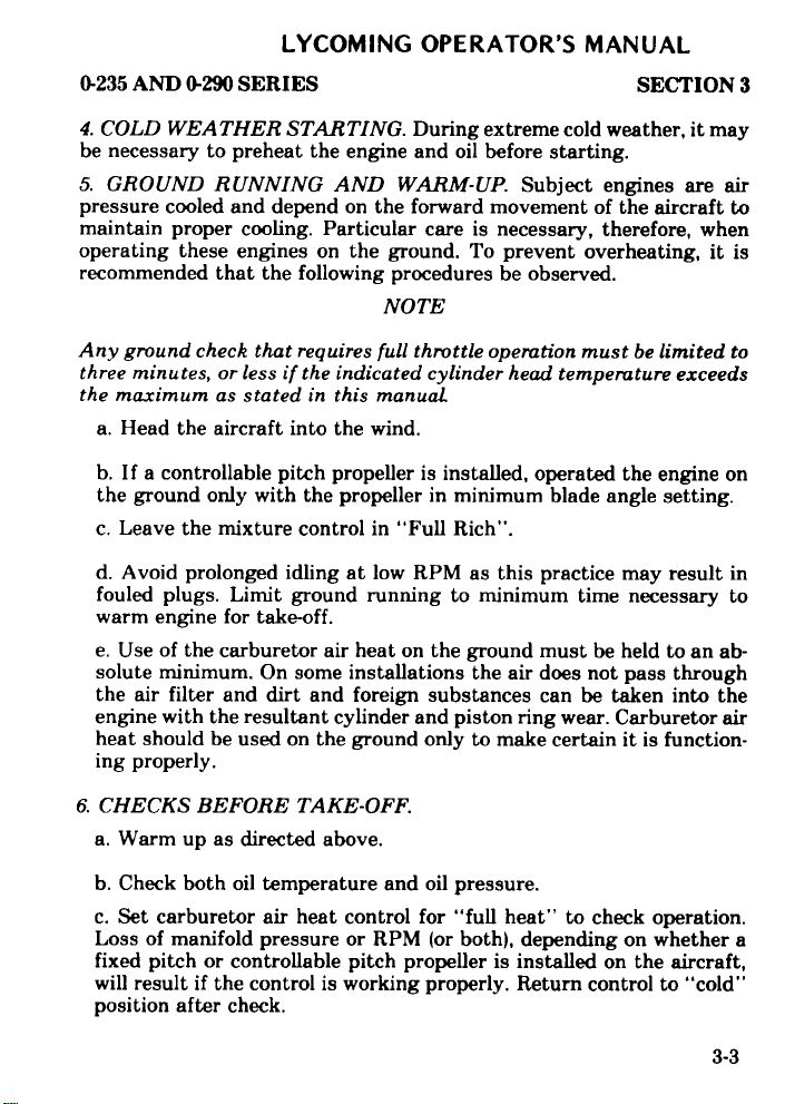
4. COLD
0-290
SERIES
WEATHER STARTING.
be necessary to preheat
5. GROUND
pressure
maintain
operating
recommended
Any ground check
three minutes,
the maximum
RUNNING AND
cooled and depend
proper
cooling.
these engines
that the
that requires
or less if
as stated in this
a. Head the aircraft
b. If
a controllable
the ground only
c.
Leave the mixture
pitch propeller
with the propeller in minimum
d. Avoid prolonged
fouled plugs.
warm engine
e. Use of the
solute minimum.
Limit ground
for take-off.
carburetor air
On some
the air filter and dirt
engine
with the resultant
heat should be
ing
properly.
used on the ground
During
the engine and oil
extreme cold
before starting.
WARM-UP.
on the forward
Particular
on the ground.
following procedures
care
is necessary,
To prevent
movement
be
NOTE
the indicated cylinder
into the
full throttle
manual
wind.
operation must
head temperature
is installed, operated
control in "Full Rich".
idling at
low RPM as
running
to minimum
this practice may
heat on the ground
installations
the air does
and foreign substances can
cylinder
and piston ring
only to
make certain it
SECTION
weather, it
Subject engines
of the aircraft
therefore,
overheating,
observed.
be limited to
the engine
blade angle setting.
time necessary
must be held
not pass through
be taken into the
wear. Carburetor
is function-
3
may
are air
to
when
it is
exceeds
on
result in
to
to an ab-
air
6. CHECKS BEFORE
a. Warm
b. Check both
c. Set carburetor
Loss
fixed pitch
will
up as directed
oil temperature
air heat
of manifold pressure
or controllable
result if the
control is working
position after check.
TAKE-OFF.
above.
and oil pressure.
control for "full
or RPM
pitch propeller
(or both), depending
heat" to check
is installed
properly.
Return control
operation.
on whether
on the aircraft,
to "cold"
3-3
a
Page 27
LYCOMING
OPERATOR'S
MANUAL
SECTION 3
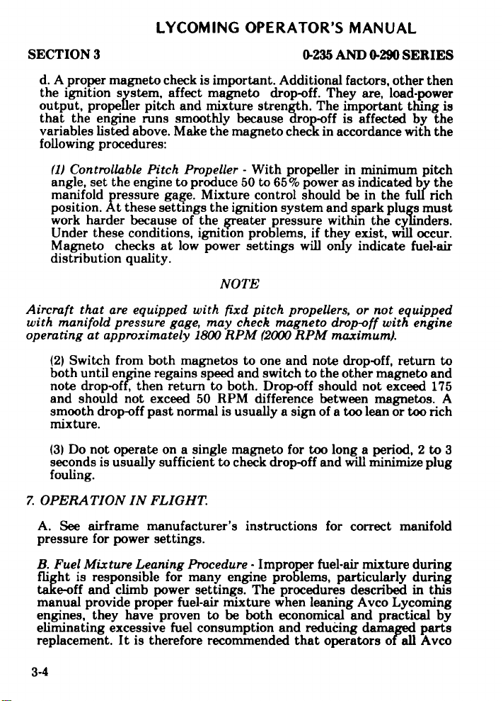
d. A proper magneto check
the ignition system,
output, propeller pitch and
that the engine runs
variables listed above. Make
following
(1) Controllable Pitch
angle, set the engine to produce
manifold
position. At these settings
work harder
Under these conditions, ignition
Magneto checks
distribution quality.
Aircraft
with manifold
operating
(2) Switch from both
both until engine
note drop-off, then
and should not exceed 50
smooth drop-off past
mixture.
(3) Do not
seconds
fouling.
procedures:
pressure gage. Mixture
that are equipped with fixd pitch
pressure
at approximately 1800 RPM
operate on a single magneto
is usually sufficient to check
affect magneto drop-off. They
smoothly because drop-off
because
of the greater
at low power settings will
gage, may check
magnetos to one and note
regains speed and switch
return to both. Drop-off should
normal is usually a sign of a
0-235 AND 0-290
is important. Additional factors,
mixture strength. The important
the magneto check in accordance
Propeller - With propeller
50 to 65% power as indicated
control should be in the
the ignition system and spark
pressure within
problems, if they exist,
NOTE
propellers, or not equipped
magneto drop-off
(2000 RPM maximum).
RPM difference between
for too long a period, 2 to
drop-off and will minimize
is affected by the
in minimum pitch
only indicate fuel-air
drop-off, return to
to the other magneto and
too lean or too rich
SERIES
other then
are, load-power
thing is
with the
by the
full rich
plugs must
the cylinders.
will occur.
with engine
not exceed 175
magnetos. A
3
plug
7. OPERATION IN FLIGHT.
A. See airframe manufacturer's instructions for correct manifold
pressure for power settings.
B.
Fuel Mixture Leaning Procedure
flight is
take-off and climb
manual provide proper
engines, they
eliminating excessive
replacement. It is therefore
responsible for many engine
power settings. The procedures
fuel-air mixture when leaning
have proven to be both economical
fuel consumption and reducing
recommended that operators
-Improper fuel-air mixture
problems, particularly during
described in this
Avco Lycoming
and practical by
damaged parts
of all Avco
during
Page 28
LYCOMING OPERATOR'S MANUAL
AND 0-290 SERIES
0-235
Lycoming
tion any time
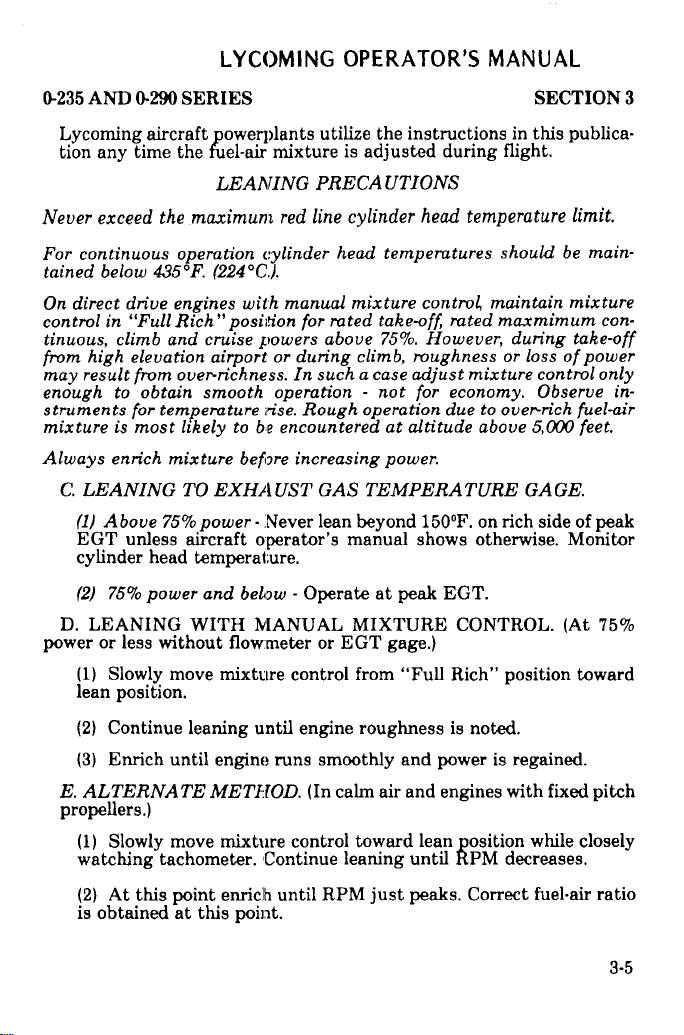
Never exceed
continuous operation
For
tained
On direct drive
control in "Full Rich"
tinuous,
from high elevation airport
result from over-richness.
may
enough to obtain
struments for temperature rise.
mixture is most likely
Always enrich
C. LEANING TO
(1) Above 75% power -Never lean beyond 150°F. on rich side of peak
EGT unless aircraft operator's manual shows otherwise. Monitor
cylinder head temperature.
(2)
D. LEANING WITH MANUAL MIXTURE CONTROL. (At 75%
power or
(1) Slowly move mixture control from "Full Rich" position toward
lean position.
aircraft powerplants
the fuel-air
LEANING
the maximum red line cylinder
below 435°F.
climb and cruise
75% power and below
less without
(224°C.).
engines with manual mixture
position for rated take-off rated
smooth operation - not
to be encountered at altitude
mixture before increasing
EXHAUST GAS TEMPERATURE
flowmeter
utilize the
mixture is
PRECAUTIONS
cylinder
powers above
or during climb, roughness or
head temperatures
such a case adjust
In
Rough operation due to over-rich
-Operate at peak
or EGT
instructions
adjusted during
head temperature limit.
control maintain mixture
75%. However,
mixture control
for economy. Observe in-
power.
EGT.
gage.)
SECTION
in this publica-
flight.
should be
maxmimum con-
during take-off
loss of power
fuel-air
above 5,000 feet.
GAGE.
3
main-
only
(2) Continue leaning until engine roughness is noted.
(3) Enrich until
E. ALTERNATE
propellers.)
(1) Slowly move
watching tachometer.
(2) At this point enrich until
is obtained at this point.
engine runs smoothly
METHOD. (In calm
mixture control toward lean
Continue leaning until
RPM just peaks. Correct
and power is regained.
air and engines with fixed pitch
position while closely
RPM decreases.
fuel-air ratio
3-5
Page 29

LYCOMING OPERATOR'S MANUAL
SECTION 3 0-235 AND 0-290 SERIES
NOTE
Leaning may be done at any altitude that the engine will accept leaning:
The greater the altitude the more important leaning becomes. Proper
leaning is important because more engine power and increased air speed
are obtained along with decreased fuel consumption, longer spark plug
life, less lead fouling,
temperatures. Engine damage from leaning the mixture does not occur
at the specified cruise power
power plant, but is the result of improper leaning atpower settings above
recommended
Use of Carburetor Heat Control
F.
conditions, it is possible for ice to form in the induction system even in
summer weather. This is due to the high air velocity through the car-
buretor venturi and the absorption of heat from this air by
evaporization of the fuel. The temperature in the mixture chamber
may drop 20°F. to 70°F. below
this air contains a large
cause
begin in the vicinity of the
extent that a drop in manifold power output results. This loss of power
is reflected by a drop in manifold
with constant
RPM in
detected, this condition will continue to such an extent that the
reduced power will cause complete engine stoppage.
To avoid this condition, all installations are equipped with a system
for preheating the incoming air supply to the carburetor. In this way,
sufficient heat is added to replace the heat loss to vaporization of fuel,
and the mixing
point of water. This air preheater is essentially a tube or jacket
through which the exhaust pipe from one or more cylinders is passed,
and the air flowing over these surfaces is raised to the required
temperature before entering the carburetor. Consistently high
temperatures are to
decided variation of the mixture. High charge temperatures also favor
detonation and preignition, both of which are to be avoided if normal
service life
the proper method
cruise.
precipitation in the form
speed propellers and a drop
installations equipped with
chamber's temperature cannot
is to be expected from the
and more normal oil
for the model engine in a basically
-Under certain moist atmospheric
the temperature of the incoming
amount of moisture, the
of ice. These ice formations generally
butterfly and will often build
pressure in installations
fixed pitch propellers. If not
be avoided because of a loss
engine. The following outline
of utilizing the carburetor
and cylinder head
healthy
air. If
cooling process will
up to such an
equipped
in manifold pressure and
drop to the freezing
of power and a
is
heat control.
Page 30

0-235
AND 0-290 SERIES
LYCOMING
OPERATOR'S
MANUAL
SECTION
3
(1) Take-Off- Take-off
cold position. The possibility
remote.
(2) Flight
the cold
foggy or hazy
lookout
Operation -The carburetor
position during normal flight
days, regardless of outside temperature,
for loss of power. This
countable loss in manifold
whether
aircraft. When
and
a constant speed or fixed pitch
this situation arises, apply
open the throttle to limiting
in a slight additional
this drop will
system.
be regained
When the ice has been
the carburetor heat
In those aircraft
partial
heat may be used
freezing
Caution must
that do not have
form that
raised
crystals
ice due
carburetor.
aircraft that
point (32°F.).
would ordinarily
in temperature
are melted
to the temperature
It is advisable,
are not equipped with a carburetor
be exercised when operating
equipped
a carburetor
into liquid form.
should be made with
carburetor heat in full
of icing at wide throttle
air heat control should
operations. On damp, cloudy,
loss of power will be shown
pressure or RPM or
both, depending on
propeller is installed on the
full carburetor air heat
manifold pressure. This will
drop in manifold pressure which
as the ice is melted
out of the
melted from the induction
control should be returned to
to keep the
WARNING
air temperature
pass through
by use
drop as it
therefore,
with a carburetor
mixture temperature
the induction
of partial heat
This moisture
passes through
to use
air temperature
with partial heat on aircraft
gage. Moisture
to the point
can form carburetor
either full
air temperature gage.
opening is very
be left in
keep a sharp
by unac-
result
is normal and
induction
system,
the cold position.
gage,
above
the
in crystal
system, can
where the
the venturi of
heat or
no heat in
be
the
(3)
Landing Approach
- In making
buretor air heat should
However,
Heat" should
under
heat should
See aircraft
if icing
conditions are
be applied.
these conditions,
be returned to "Full Cold"
flight manual for specific
usually be in the "Full
an approach
known or suspected,
In the case
as for
that full power
an aborted
landing, the carburetor
prior to power application.
instructions.
for a landing,
Cold" position.
then
need be applied
car-
"Full
3-7
Page 31

LYCOMING
OPERATOR'S
MANUAL
SECTION 3 0-235 AND 0-290 SERIES
8. ENGINE FLIGHT CHART.
Fuel and Oil
Model
O-235-C, -E, -H2C
O-235-F, -G, -J, -K, -L, -M,
O-290-D, -D2 ....
* Refer to the latest edition of Service Instruction No. 1070.
Aviation grade
are
approved for continuous
. . . . . .....
100LL fuels in which the lead
.. . . . ................
-N, -P .... . 100/100LL
NOTE
content is limited to 2 c.c. per gallon
use in the above listed engines.
*Aviation Grade
. 80/87 octane minimum
octane minimum
. ..80/87 octane minimum
Fuel
**Recommended Grade Oil
Average
Ambient Air
All Temperatures
Above 80°F.
Above 60°F. (15.5°C.)
30 (-1.11°C.) to 90°F. (32.2°C.) SAE 40 SAE 40
0°(-17.8°C.) to 70°F.
Below 10°F. (-12.2 C.)
** Refer to the latest edition of Service Instruction No. 1014.
Oil Sump Capacity 6 Qts. 8 Qts.
Minimum Safe Quantity
of Oil in Sump
It is recommended that the lubricating oil be changed every 50 flying hours (or
every 25 hours,
Oil Pressure, psi
0-235 Series
-C, -E, -F, -G, -H2C, -J, -K, -M
-B,
-L*, -N
-P 90 55 15
* Front of engine
(26.6°C.)
(21.1°C.) SAE 30
if engine does not have
OPERATING CONDITIONS
MIL-L-6082
Grades
....--
SAE 60 SAE
SAE 50
SAE 20
0-235 Series -D2 Series
2 Qts.
a full-flow oil filter).
Maximum Minimum
90 60
90 60
90
MIL-L-22851
Ashless Dispersant
Grades
SAE 15W50 or 20W50
60
SAE 40 or SAE 50
SAE 40, 30 or 20W40
SAE 30 or 20W30
0-290-D,
2 Qts.
Idling
25
15
50 15
Page 32

LYCOMING
OPERATOR'S
MANUAL
SECTION 3
All 0-235
-L, -N, -P
0-290 Series
-D
-D2
-D2
Fuel
All
0-290-D
Above
30 (-1.11°C.)
0° (-17.8°C.) to 70°F.
Below
series,
pressure
0-235 models,
Average Ambien
(psi)
Temperature
60°F. (15.5°C.)
to 90°F.
10°F.
(-12.2°C.)
OPERATING
except
O-290-D2
290-D2
t Air
(32.2°C.)
(21.1°C.)
0-235 AND 0-290 SERIES
CONDITIONS
START/WARM-UP
100
115
Maximum
85
90 60 25
START/WARM-UP
100
Maximum
5
5
Desired
180°F.
180°F. (82°C.)
170°F.
160°F. (71°C.)
(Cont.)
Minimum
60
Desired Minimum
3
3
Oil Inlet Temperature
(82°C.)
(77°C.)
Idling
25
0.5
0.5
Maximum
245°F. (118°C.)
245"F.
(118°C.)
245 F. (118"C.)
245°F.
(118 C.)
Engine
operation.
oil temperatu
not be below 140"F.
(60"C.) during continuous
3-8A
Page 33

0-235
AND 0-290
LYCOMING
SERIES
OPERATOR'S
MANUAL
SECTION
3
OPERATING
Operation
Normal
Performance Cruise
Economy
Normal Rated
Performance Cruise
Economy
Take-Off
Normal
Performance Cruise
Economy Cruise
Rated
(75% Rated) 2350 86 7.3
(65%
(75% Rated)
(65% Rated)
(75%
(65%
Cruise
Rated)
Cruise
Rated
Rated) 2350
Rated)
RPM
2800 115
2250 75
2800
2500
2400
2800
2600
2250
CONDITIONS
HP
0-235-C,
0-235-F, -G, -J
125 10.7
94 7.3
81 5.8
0-290-D
130
125
94 7.5
81
0-290-D2
Fuel
Cons.
Gal./Hr.
-E
10.7
5.8
Series
11.9
6.5
Series
(CONT.)
Max. *Max.
Oil Cons.
Qts./Hr.
0.52
0.29
0.25
0.56
0.31
0.27
0.56
0.31
0.27
Cyl. Head
Temp.
500°F. (2600C.)
500°F. (260°C.)
500°F. (260°C.)
500°F. (260°C.)
500°F. (260°C.)
500°F. (260°C.)
500°F. (260°C.)
500°F.
(260°C.)
500°F.
(260°C.)
500°F.
(260°C.)
Take-Off
Normal
Performance Cruise
Economy Cruise
* - At
cylinder head
ing continuous
Rated
(75% Rated)
(65%
Rated) 2200
Bayonet Location
temperatures
operation.
2800
2600
2350 101
140
135
87 6.3
- For maximum
between 150°F.
12.6
7.2
service life
(65°C.) and 400°F.
0.60
0.34
0.29
500°F. (260°C.)
500°F.
(260°C.)
500°F.
(260°C.)
500°F.
(260°C.)
of the engine, maintain
(204°C.) dur-
3-9
Page 34

LYCOMING OPERATOR'S
MANUAL
SECTION 3
OPERATING
Operation
Normal
Performance Cruise
Economy Cruise
Take-off 2800
Normal Rated 2700
Performance Cruise
Economy Cruise
Take-off 2800
Normal Rated 2600
Performance Cruise
Economy Cruise
Rated
(75% Rated) 2500
(65% Rated) 2400
(75% Rated) 2425
(65% Rated) 2300
('75% Rated) 2350
(65% Rated) 2250
RPM HP Gal./Hr.
2800
CONDITIONS
Fuel
Cons.
0-235-K, -L, -M
118 9.5
89 6.7
77 5.8
0-235-K2C
118
115 9.2
86 6.4
75 5.6
0-235-H Series
115 --
108 10.7
81 7.3
70 5.8
0-235 AND 0-290 SERIES
(CONT.)
Max. Max.
Oil Cons. Cyl. Head
Qts./Hr.
.39 500°F. (260°C.)
.30
.27
.38
.29
.25
.36
.27
.23
Temp.
500°F. (260°C.)
500°F.
(260°C.)
500°F. (260°C.)
500°F. (260°C.)
500°F. (260°C.)
500°F. (260°C.)
500°F. (260°C.)
500°F. (260°C.)
500°F. (260°C.)
500°F. (260°C.)
Take-off 2800
Normal Rated 2550
Performance Cruise
(75% Rated) 2300
Economy Cruise
65% Rated) 2200
3-10
0-235-N, -P
116
108 9.2
81
70 5.3
6.2
.36
.27
.23
500°F. (260°C.)
500°F.
(260°C)
500°F. (260°C.)
500°F. (260°C.)
Page 35

LYCOMING
SECTION 3 0-235 AND 0-290 SERIES
.9 SHUT-DOWN PRO('EDURE.
a. Idle engine at approximately 800 to 900 RPM until there is a
decided drop in cylinder head temperature.
b. Move mixture control to "Idle Cut-Off".
c. After engine stops, set magneto switch at the "off" position; this
will prevent after-firing.
OPERATOR'S
MANUAL
Revised
March.
1982
3-10A
Page 36

LYCOMING OPERATOR’S MANUAL
0-235 AND 0-290 SERIES
hRxNRE SETTING
SECTION 3
CURVE NO. 8210
Figure 3-l. Power and Fuel Consumption Curve
o-235-c
3-11
Page 37

Figure 3-2. Sea Level and Altitude
Performanc
e - 0-235-C1, -El, -H2 Series
Page 38

LYCOMING OPERATOR’S MANUAL
0-235 AND 0-290 SERIES SECTION 3
Figure 3-3. Fuel Flow vs Percent Rated Power.
0-235-C1, -El, -H2 Series
3-13
Page 39

Figure 3-4. Sea Level and Altitude Performance. 0-290-D
Page 40

LYCOMING OPERATOR’S MANUAL
0-235 AND 0-290 SERIES
.2-=---J-
SECTION 3
CURVE NO. 8583-A
--
Figure 3-5. Power and Fuel Consumption Curve-
0-290-D
3-15
Page 41

Page 42

LYCOMING OPERATOR’S MANUAL
0-235 AND 0-290 SERIES
SECTION 3
Figure 3.7. Power and Fuel Consumption Curve-
0-290-D2, -D2A
3-17
Page 43

Page 44

LYCOMING OPERATOR'S MANUAL
0-235 AND
The following is
Performance
horsepower
manifold pressure
from
1. Determine equivalent
mance curve
2400 RPM and
2. Repeat above
-Point "B").
3. Transfer
(Example - Point "C").
4. Connect point
5. Read
feet with a power setting of
99.5, Point "D").
6. Correct power approximately
air temperature
Add corrections for
temperatures
temperature of
variation.
approximately
add correction:
0-290 SERIES
USING
curve on opposite page)
CURVE TO FIND
an example of how to use the
curves,
being delivered
and air inlet
for observed
23.8 in. Hg., locate
procedure on sea level performance
value obtained
"A" and point "C"
horsepower
from the standard altitude
above
22°F. at an altitude
1% for
each 10°variation
3 horsepower.
99.5 + 3 = 102.5 horsepower,
printed
on line "CA" for
temperatures below standard,
standard.
ACTUAL HORSEPOWER
on these pages,
by the engine
temperature.
is for illustration purposes
full throttle horsepower
manifold pressure
Point "A").
in Step 2
2400 RPM and 23.8 in. Hg.,
to the altitude
with a straight line.
given altitude
1% for each 10°F. variation
(Example -
of 1800
is 3%. 3%
Since
temperature
Sea Level and Altitude
to determine
for given
This example
and RPM
temperature shown below.
With an air
feet, 52°F. - 22"F.
of 99.5 horsepower
Point "E").
SECTION
-
altitude, RPM,
(using figures
only.
on altitude perfor-
(Example
curve (Example
performance curve
(Example -At
horsepower is
is below standard,
actual
- At
1800
in intake
subtract for
inlet
= 30°F.
3
is
STANDARD
Pressure Altitude
(Thousands)
Standard Altitude
(Temperature
°F.)
ALTITUDE TEMPERATURES
SL
2 4 6 8 10
59 52 45
38 31 23 16 9
12 14 16 18
IN DEGREES
20 22 24
+ 2 -5 -12
F.
-19 -27
3-19
Page 45

LYCOMING OPERATOR’S MANUAL
SECTION 3 o-235 AND 0.290 SERIES
3-20
Figure 3-9. Power and Fuel Consumption Curve .
0-290-D2B,-D2C
Page 46

LYCOMING OPERATOR’S MANUAL
o-235 AND O-290 SERIES
SECTION 3
Figure 3-10. Fuel Flow vs Percent Rated Power -
0-235-F. -G Series
3-21
Page 47

Page 48

LYCOMING
OPERATOR'S
MANUAL
0-235
AND 0-290
9
SERIES
FUEL FLOW VS. PERCENT RATED POWER
AVCO LYCOMING 0-235-K, -L, -M SERIES
COMPRESSION RATIO 8 50 1
SPARK ADVANCE 20°BTC
CARBURETOR. MARVEL SCHEBLER MA-3A or MA-3PA
FUEL GRADE. MINIMUM 100/1OOLL
I
SECTION 3
PERCENT RATED POWER
Figure 3-12. Fuel Flow vs Percent Rated Power -
0-235-K, -L, -M Series
3-23
Page 49

3-24
Figure
SECTION
3-13.
Sea
Level
and
Altitude
Performance
-
0-235-K,
-L,
-M
Series
3
LYCOMING
OPERATOR'S
0-235
AND
MANUAL
0-290
SERIES
Page 50

0-235
0
I
AND
10
9
8
7
0-290
LYCOMING
OPERATOR'S
SERIES
FUEL FLOW vs. HORSEPOWER
LYCOMING
MINIMUM-ALLOWABLE FUEL FLOW
0-235-N,
MANUAL
-P SERIES
CURVE NO. 13401
SECTION
3
5
0
60
70 80
90
BRAKE HORSEPOWER
100
110
120
Figure 3-14. Fuel Flow vs. Horsepower
0-235-N, -P Series
3-25
Page 51

3-26
Figure
3-15. Sea Level
0-235-N,
and Altitude
-P
Series
Performance
SECTION 3
z
z
LYCOMING
OPERATOR'S
0-235 AND 0-290 SERIES
MANUAL
--
Page 52

LYCOMING
PERIODIC INSPECTIONS
Pre-Starting Inspection ................................. 4-1
Daily Pre-Flight ................................ ..... 4-2
25-Hour Inspection
50-Hour Inspection
100-Hour Inspection
400-Hour Inspection ..... ............................... 4-5
Non-Scheduled Inspection ............................... 4-5
.....................................
.....................................
....................................
OPERATOR'S
MANUAL
Page
4-2
4-2
4-4
Page 53

0-235
AND
0-290
LYCOMING
SERIES
OPERATOR'S
MANUAL
SECTION
4
Perhaps
the aircraft
regular
found.
The
pages
the
tion instructions.
Pre-Starting
aircraft
the
phasize.
responsible
centration,
carelessness
operator
do
engine
general
The
importance
Among
no other
and
checks
not constitute
only.
Inspection
prior to
condition
Statistics
to
the major
reluctance
bred
PERIODIC
factor
its components
for
minor
should
Consult
the
first flight
bear
of
of proper
prove
poor
pre-flight.
causes
by familiarity
SECTION
INSPECTION
NOTE
is quite
a
the
-The
the aircraft
troubles
in mind
complete
airframe
daily
of
so important
as
faithful
and
that
aircraft
manufacturer's
pre-flight
the day.
and engine.
pre-flight
several
hundred
of poor
pre-flight
to acknowledge
and
haste.
4
to safety
and diligent
prompt
the items
inspection,
inspection
This
inspection
inspection
accidents
inspection
the need
repair
listed
handbook
cannot
occur
for
and
durability
attention
when
in the
but
are
is a check
is to
be over
yearly
are lack
a
check
they are
following
meant
for
for addi-
of
the
determine
em-
directly
of
con-
list,
of
to
4-1
Page 54

LYCOMING OPERATOR'S MANUAL
SECTION
1. DAILY PRE-FLIGHT.
a. Be sure
b. Be sure magneto ground wires are connected.
c. Check oil level.
d. See that
e. Check
at 50 hour inspection. Repair any major leaks before aircraft is flown.
f. Open the fuel drain to remove
ment.
g. Make sure all shields and
missing or
aircraft is flown.
h. Check controls for general condition, travel and freedom of opera-
tion.
i. Induction system air filter should be inspected and serviced in ac-
cordance with the airframe manufacturer's recommendations.
2. 25-HOUR
time,
a 50 hour inspection including draining and renewing lubricating oil.
3. 50-HOUR
flight inspection,
every 50 hours of operation.
4
the "Off"
all switches
fuel tanks are
fuel and oil line connections,
damaged, repair or replacement
INSPECTION. After the
new, remanufactured or newly
INSPECTION. In addition
the following maintenance checks
are in
full.
cowling are in place and secure.
any accumulation of water
overhauled engines should
0-236 AND 0-290
position.
note minor indications for
should be made before the
first twenty-five hours operating
to the items listed for daily
should be made after
SERIES
repair
and sedi-
If any are
undergo
pre-
Ignition System - Remove
a.
Replace if necessary.
Examine spark plug leads of cable and ceramics for corrosion and
deposits. This condition
cleaning of the spark plug
proper
condition is found, clean the cable ends, spark plug walls and ceramics
with a dry, clean
ketone. All parts should be clean and dry before reassembly.
Check ignition harness for security of mounting clamps and be sure
connections are tight at spark plug and magneto terminals.
4-2
cloth or a clean cloth moistened
spark plugs; test, clean and
is evidence of either leaking
walls or connector ends. Where
spark plugs, im-
with methyl-ethyl
regap.
this
Page 55

LYCOMING OPERATOR'S MANUAL
0-235 AND 0-290 SERIES SECTION 4
b. Fuel and Induction System - Check primer lines for leaks and
security of clamps. Drain carburetor and clean carburetor fuel
strainer. Check mixture
freedom of movement, security of clamps and lubricate if necessary
Check carburetor air intake ducts for leaks, security, filter damage;
evidence of dust or other solid material in the ducts is indicative of
inadequate filter care or damaged filter. Check vent lines for evidence
of filter or oil seepage; if present, fuel pump may require replacement.
c. Lubrication System - Check oil lines for leaks, particularly at con-
nections; for security of anchorage and for wear due to rubbing or
vibration, for dents and cracks.
Drain and refill sump with new oil on installation not employing
replaceable external oil filter. See the latest revision to Service In-
struction
are listed in Section 3, Paragraph 8 of this manual.
Remove oil suction and oil pressure screens and clean thoroughly.
Note carefully for presence of metal particles that are indicative of
internal engine damage.
If engine is equipped with external oil filters, replace at this time.
Before disposing of filter, check interior for traces of metal particles
that might be evidence of internal engine damage.
No. 1014 for recommended
control and throttle
lubricating oils. Seasonal
linkage for travel,
grades
d. Exhaust
cylinders
removed and machined flat before they are reassembled and tightened.
Examine exhaust manifolds for general condition.
e. Cooling System - Check cowling for damage and secure anchorage.
Any damaged or missing part of the cooling system must be repaired
or replaced before the aircraft resumes operation.
f. Cylinders - Check rocker box covers for evidence of oil leaks. If
found, replace gasket and tighten screws to specified torque (50 inch
pounds).
Check cylinders for evidence of excessive heat which is indicated by
burned paint on the cylinder. This condition is indicative of internal
damage to the cylinder and, if found, its cause must be determined and
corrected before the aircraft resumes operation.
System - Check attaching
for evidence of leakage. If
flanges at exhaust ports
they are loose, they must
on
be
4-3
Page 56

SECTION
Heavy
and
barrel
cant used
leakage
condition
and
operation.
ditions,
4.
100-HOUR
pre-flight
shouldbe
a.
Electrical
cessories.
Replace
and
cleanliness.
b.
Magnetos
oil
in the breaker
cloth.
The
accordance
magneto
Paragraph
c.
Engine
temperature
mounting,
d
Cylinders
LYCOMING
4
discoloration
attachment
during
which
is
the
and
made
faulty clamps
to
assembly
stops
neither
cylinder
Any
felt
engine
lb of
Accessories
tight
harmful
If
it can
INSPECTION.
50
hour
after
every
System
shielded
-Check
compartment,
located
with
the magneto
timing.
this manual.
and
pressure
connections
-Check
and appearance
area is
usually
of the barrel
after
cylinder
nor detrimental
be proven
should
be replaced.
In
inspection
-Check
cables
or loose
condition
at
- Engine
visually
addition
one
hundred
all
wiring
that
wires
of breakers
if found,
the breaker
Timing
mounted
sensing
and
for
OPERATOR'S
0-235 AND
of seepage
due to
emission
at
has
that
the following
manufacturer's
procedure
units
terminals.
cracked
the factory,
been
in service
to the
the leakage
to
the
hours
of
connected
are damaged
and check
points.
wipe
points
is
accessories
should
or broken
MANUAL
at
the cylinder
engine
exceeds
items
maintenance
operation.
to
the engine
should
terminals
Check
dry with
should
be
instructions.
described
be checked
fins.
0-290
SERIES
of thread
or
by slight
for awhile.
performance
these
listed
for daily
be
replaced.
for
security
for
excessive
a clean
lintless
lubricated
in Section
such
as pumps,
for
head
lubri-
gas
This
con-
checks
or
ac-
Check
secure
in
5,
e. Engine
security
ly worn.
f Primer
for
equal
g.
Valve
Paragraph
h.
Carburetor
The
correct
4-4
Mounts
and
excessive
Nozzles
flow.
Rockers
11 for valve
-
Check
torque
- Check
wear.
-
Disconnect
(0-235
and
rocker
throttle
for these
engine
0-290-D)
mounting
Replace
primer
clearance.
body
screws
any
bushings
nozzles
-
Check
attaching
is 40 to
bolts
and
that
from
engine
clearance.
screws
50 inch
pounds.
bushings
are excessive-
and
check
See Page
for
5-15,
tightness.
for
Page 57

LYCOMING
0-235 AND 0-290 SERIES SECTION 4
OPERATOR'S
MANUAL
i. Lubrication
filter.
5. 400-HOUR INSPECTION.
pre-flight, 50 hour
check should be made after every 400 hours of operation.
Valve
Inspection - Remove rocker
valve rockers when valves are closed. Look for evidence of abnormal
wear or broken parts
and spring seat. If any indications are found, the cylinder and all of its
components
assembly) and inspected for further damage. Replace any parts that do
not conform with limits shown
System - Drain and renew
In addition to
and 100 hour inspections,
box covers and check for freedom
in the area of the valve tips, valve
should be removed (including
in the latest publication
lubrication oil. Replace
the items listed for daily
the following maintenance
keeper, springs
the piston and connecting rod
of Special Ser-
oil
vice Publication No. SSP1776.
6. NON-SCHEDULED INSPECTIONS. Occasionally, service bulletins
or service instructions are issued by Avco Lycoming Division that re-
quire inspection procedures
publications, usually
obsolete after corrective modification has been accomplished. All such
publications are available from Avco ,ycoming distributors, or from the
factory by
tion information. Maintenance facilities should have an up-to-date file of
these publications available at all times.
subscription. Consult Service
are limited to specified engine
that are not listed in
Letter No. L114 for subscrip-
this manual. Such
models and become
of
4-5
Page 58

LYCOMING OPERATOR'S
MAINTENANCE PROCEDURES
Ignition and Electrical System
Harness and Wire Replacement ......................... 5-1
Timing Magnetos to Engine ............................ 5-1
Generator or Alternator
Fuel System
Repair of Fuel Leaks .................................. 5-7
Carburetor
Fuel
Grades and Limitations
Air Intake Ducts
Idle Speed and Mixture
Lubrication System
Inlet Screen Assembly
and Filters .........
Output .........................
...................... 5-7
...........................
Adjustment .....................
MANUAL
.................. 5-7
Page
5-6
5-7
5-7
Oil Grades and Limitations ........................... 5-8
Oil Sump
Oil Suction and Oil
Oil Relief Valve .................... .................. 5-9
Cylinder Assembly
Removal of Cylinder Assembly ......................... 5-9
Assembly of Cylinder Assembly ....................... 5-12
Generator Drive Belt Tension ........................... 5-14
Capacity ....................................
Pressure Screens .....................
5-8
5-8
Page 59

LYCOMING
OPERATOR'S
MANUAL
0-235 AND 0-290 SERIES
SECTION 5
MAINTENANCE PROCEDURES
The procedures described in this section are provided to guide and in-
struct personnel in performing
required in conjunction with the periodic inspections listed in the
preceding section. No
operations that will be found in the applicable Avco Lycoming Overhaul
Manual.
1. IGNITION AND ELECTRICAL SYSTEM.
a. Ignition Harness and Wire Replacement - In the event that an ig-
nition harness
ing diagram to be sure harness is correctly installed. Mark location of
clamps and
locations.
b.
Timing Magnetos to Engine
magnetos
model application)
are
the same
Either the impulse coupling
plicable) is installed on the left side of the engine.
clips to be certain the replacement
are used on this series
attempt is made to include repair
or an individual lead is to be
the timing
for
all magnetos.
such maintenance operations
replaced, consult the wir-
is clamped at correct
- Although several combinations
engines, (see Table of Models
procedures,
NOTE
or retard breaker magneto (whichever
in the following
SECTION 5
that may be
and replacement
for
paragraphs,
is ap-
of
(1) Remove
the spark plug hole. Rotate the crankshaft in direction of normal
rotation until the compression stroke is reached, this is indicated by
a positive pressure inside
the spark
normal rotation until the
the starter ring
at
the two o'clock position on the
Consult specification
At this point, the engine
a spark plug from No. 1 cylinder
plug hole. Continue rotating
gear is in exact alignment with
the cylinder tending to
the crankshaft in direction
advance timing mark on the
front face of the starter
for correct timing mark for
is ready for assembly of the
and place a thumb over
push the thumb off
front face of
the small hole located
housing.
your installation.
magnetos.
5-1
of
Page 60

LYCOMING
OPERATOR'S
MANUAL
SECTION 5
0-235
AND 0-290
SERIES
5-2
FIRING
Figure 5-1. Ignition Wiring Diagram
ORDER
1-3-2-4
Page 61

LYCOMING OPERATOR'S MANUAL
0-235 AND 0-290 SERIES SECTION 5
Figure 5-2.
FIRING ORDER 1-3-2-4
Ignition Wiring Diagram
(Optional)
5-3
Page 62

LYCOMING
OPERATOR'S
MANUAL
SECTION 5
0-235 AND
0-290 SERIES
5-4
Figure
FIRING ORDER 1-3-2-4
5-3. Ignition
Wiring
Diagram
(Optional)
Page 63

LYCOMING OPERATOR'S MANUAL
0-235 AND 0-290 SERIES SECTION 5
All timing
one cylinder advance engine
magnetos.
The
method of positioning the
cylinder advance engine firing position is contained in the following
paragraphs. The method for Bendix magnetos may be found on page 5-6.
(Impulse Coupling Magneto) Hold the No. 1 lead wire spring 1/16 in. to
1/8 in. away from the magneto
click at a time until a strong spark jumps between the spring and the
frame. Hold the
the
point where it trips and the
proximately 25 until
vent plug hole. Hold the rotor by inserting the timing pin, and line the
timing pin with the center of the vent plug hole.
(Conventional Magneto) Hold the No. 1 lead wire spring 1/8 in. away
from the frame.
flux
lines until a strong spark occurs
to the
flux until the timing pin hole
hole and insert
procedures, except positioning
firing position, are the
Slick magnetos in the number
frame and turn the impulse
magneto firmly so the coupling
spark occurs. Reverse the rotation
the timing pin hole appears
Turn the gear counter-clockwise
at the lead. Reverse the rotation
appears in the center of the vent
the timing pin into
the hole.
the magneto in the number
same for all
one
coupling one
will not move beyond
ap-
in the center of the
vigorously through the
in-
plug
5-5
Page 64

LYCOMING OPERATOR'S MANUAL
SECTION 5 0-235 AND 0-290 SERIES
NOTE
If the crankshaft is accidently turned in the direction opposite normal
rotation, repeat the above procedure as accumulated backlash will make
the final timing incorrect.
(2) Remove the inspection plugs from both magnetos and turn the
drive
shafts in direction of normal
chamfered tooth on the distributor gear is aligned in the center of
the inspection window. Being sure that the gear does not move from
this position, install gaskets and magnetos on the engine. Secure
with washers
and nuts; tighten
NOTE
rotation until the first
only finger tight.
painted
In order to turn
pawl
on the
(3) Using a battery powered timing light, attach the positive lead to
a suitable terminal connected to the ground terminal of the magneto
and
the negative lead to any unpainted
the magneto in its mounting
on,
then slowly turn it in the opposite
out. Bring the magneto back slowly until the light just comes on.
Repeat this with the second magneto.
Some
timing lights operate in the
light comes on when the breaker points open. Check your timing light in-
structions.
(4) After both magnetos have
to
ascertain that both magnetos
(5)
Back off the crankshaft a few
out. Bring
until
the timing mark and the
alignment.
Tighten nuts
c. Generator or Alternator Output - The generator or alternator
(whichever is applicable) should be checked to determine that the
specified voltage and current are being obtained.
the shaft on an impulse coupling
impulse coupling
the crankshaft slowly back
At this point, both lights
to specified torque
with
the finger.
flange to a point where the
NOTE
reverse manner as described above,
been timed, check, as described
are set to fire simutaneously.
degrees, the timing lights should
hole in the starter housing
(150 inch pounds).
magneto, depress the
portion of the engine.
direction until the light
in direction of normal rotation
should go on simultaneously.
Rotate
light comes
goes
the
below,
go
are in
Page 65

LYCOMING OPERATOR'S MANUAL
0-235 AND 0-290 SERIES SECTION 5
2. FUEL SYSTEM.
a. Repair
is replaced, only a fuel soluable lubricant, such as clean engine oil or
Loctite Hydraulic Sealant, may be used on the threads. Any other
thread lubricant
b. Carburetor Inlet
distortion or openings
ditions. Clean assembly in
stall
in the throttle
c. Fuel Grades
subject engines is listed in the Engine Flight Chart on page 3-8 of this
manual. In the event
locations, it is
octane then specified is not to be used. Under no circumstances should
automotive
These engines are equipped with solid stem valves and should use higher
octane fuel only for limited
be familiar with Service Instruction No. 1070 regarding specified fuel for
Avco Lycoming engines.
d Air Intake Ducts and Filter - Check all air intake ducts for dirt or
restrictions. Inspect and service air filters as instructed in the air-
frame manufacturer's handbook.
e. Idle Speed and Mixture Adjustment -
(1) Start the engine and warm up in the usual manner until oil and
cylinder head temperatures are normal.
of Fuel Leaks -In the event a
or compound
Screen Assembly -Remove
in the strainer. Replace for
the screen asembly, place the
body, then tighten to
and Limitations -The recommended
that the specified fuel is not
permissible to use higher octane
fuel be used (regardless
must not be used.
solvent and dry with compressed
NOTE
operation. It is recommended
line or fitting in the fuel system
and check the screen for
either of these con-
air. To in-
gasket on the assembly and
35 - 40 inch pounds torque.
aviation grade
available at some
fuel. Fuel of a lower
of octane rating).
that personnel
install
for
(2) Check magnetos. If the "mag-drop" is normal, proceed with idle
adjustment.
(3) Set throttle stop screw so that the engine idles at the airframe
manufacturer's recommended idling RPM. If the RPM changes
appreciably after making idle mixture adjustment during the suc-
ceeding steps, readjust the idle speed.
Page 66

LYCOMING
OPERATOR'S
MANUAL
SECTION
5
(4) When the idling speed
mixture control lever
0-235 AND 0-290
has been stabilized, move
with smooth, steady pull toward
SERIES
the cockpit
the "Idle Cut-
Off" position and observe the tachometer for any change during the
leaning process. Caution
must be exercised to
return the mixture
control to the "Full Rich" position before the RPM can drop to a
point where the engine cuts out. An increase of more than 50 RPM
while "leaning"
out indicates an excessively
rich idle mixture. An
immediate decrease in RPM (if not preceded by a momentary in-
crease) indicates
the idle mixture
is too lean.
If the above indicates that the idle adjustment is too rich or too
lean, turn the idle mixture
correction,
and check this new
procedure. Make additional
adjustment in the direction
position by repeating the
adjustments as necessary
required for
above
until a check
results in a momentary pick-up of approximately 50 RPM. Each
time the adjustment is changed,
RPM to clear the engine
Make the final
adjustment of the idle speed
the desired idling RPM
before proceeding with
with closed throttle. The
the engine should be run
adjustment to obtain
above method aims
up to 2000
the RPM check.
at a setting that will obtain maximum RPM with minimum manifold
pressure. In case the setting does not remain stable, check the idle
linkage; any looseness in this linkage would cause erratic idling. In
all cases,
allowance should be made for
the effect of weather condi-
tions and field altitude upon idling adjustment.
3. LUBRICATION SYSTEM.
a. Oil Grades and Limitations -Service the engine with grade recom-
mended in Flight Chart, Section 3-8.
b. Oil Sump Capacity -
0-235 Series .................................. 6 U.S. Quarts
0-290-D and -D2 Series .......................... 8 U.S. Quarts
Minimum Safe Quantity in Sump ................. 2 U.S. Quarts
c. Oil Suction and Oil Pressure Screens. For engines without a full-flow
oil filter, change oil and inspect and clean screens every 25 hours.
NOTE
On installations employing full-flow oil filters, step c. is not practical at
this time, but should be observed at the 100 hour inspection.
5-8
Page 67

LYCOMING OPERATOR'S MANUAL
AND 0-290 SERIES
0-235
c. Oil Relief Valve - Subject engines are equipped with either an ad-
justable
crankcase half to the rear
will maintain the oil pressure
adjusting
pressure. The non-adjustable valve can control pressure by the addi-
tion of a maximum of nine
pressure
pressure.
d Oil Relief
the operator to maintain
If the pressure
exceed the
follows:
With the engine warmed
RPM, observe the reading
above
screw the adjusting screw
pressure. Depending on installation,
ly a screw driver slot
the
turned with either a screw driver or a box wrench.
4. CYLINDER
disassembly
field operation, cylinder
entire assembly. Valve replacement should be undertaken only as an
emergency measure.
or a non-adjustable oil
of no. 3 cylinder pad. The adjustable
screw inward to increase
STD-425 washers under the cap
or a spacer (P/N 73629 or 73630)
Valve (Adjustable) -The adjustable
engine oil pressure within
under normal operating conditions
maximum or minimum specified
on the oil pressure gage.
maximum or below minimum
out to decrease pressure and
and is turned with a screw
screw driver slot plus a pinned
ASSEMBLY. Although the
and reassembly is given here,
maintenance be confined to
relief valve located in the
within specified limits by
pressure and outward to
under the cap to decrease
oil relief valve enables
the specified limits.
should consistently
limits, adjust the valve
up and running at approximately
specified limits, stop engine
the adjusting screw
driver; or may have
.375-24 castellated nut and
complete procedure for
it is recommended that, as
SECTION
right
valve
screwing the
decrease
to increase
as
2000
If the pressure is
and
in to increase
may have on-
may be
replacement of the
5
a
a. Removal of
Remove exhaust
(1)
(2) Remove rocker box drain
clips that interfere
Cylinder Assembly
manifold.
with the removal
-
tube, intake pipe, priming
of cylinder.
lines and any
Page 68

LYCOMING
SECTION 5 0-235 AND 0-290 SERIES
OPERATOR'S
MANUAL
(3) Disconnect ignition cable
Remove
approximately
(4) Remove
enabling
removed when the
(5) Remove
shroud tube.
(6) Remove
the crankcase.
as the piston
falling.
The tappets, push rods, rocker
that they can be assembled
removed.
Removal of Valves
b.
cylinder
tion.
Remove the split
ings and valve
head. Hold the valve stems so that the valve will not fall out and
remove the cylinder from the holding block. The valves may now be
removed from the inside of the cylinder.
rocker box
at top
valve rockers
the valve rockers to be removed.
cylinder is taken from
push rods
cylinder
leaves the cylinder.
over a block
Compress the valve springs
base nuts and
Do not
and Valve
of wood so
keys from the end of the valve
spring seats may now be removed
at spark plugs and remove
cover and rotate
center of the
by sliding
by grasping the
allow the piston
Hold
NOTE
arms and valves must be
in the same location from which
Springs from
as to hold the
using the valve spring compressor.
crankshaft
compression
the valve rocker
Valve rocker shaft can
the engine.
ball end and
pull cylinder
to drop against
shroud tubes
Cylinder -
valves in a closed
stem. The valve spr-
spark plugs.
until piston
stroke.
shaft aside
pulling rod out
directly away
the crankcase
to prevent their
identified so
they were
Place the
from the cylinder
is
be
of
from
posi-
c. Removal
plugs.
then proceed
on cylinder pad
discarded cylinder base
5-10
of Piston from Connecting
Insert piston pin puller through
to remove
of the crankcase. Support
Rod - Remove the piston
piston pin, assemble puller
piston pin. Do
oil ring seals or any other
not allow connecting
with heavy rubber bands,
method.
rod to
pin
nut;
rest
Page 69

LYCOMING OPERATOR'S MANUAL
0-235 AND 0-290 SERIES SECTION 5
d Removal of Hydraulic Tappet Sockets and Plunger Assemblies -
(0-290-D2 Series) It will be necessary to remove and bleed the
hydraulic
checked when
ed in the following manner: A special Avco Lycoming tool is available
for removal of the sockets and plunger assemblies. In the event the
tool is not available,
The hydraulic tappet socket may usually be removed by inserting
the forefinger
ly stick to the finger
If the
grasping
However, care must be exercised
remove
Lycoming service tool. In the event that the tool is not available, the
hydraulic tappet plunger assembly
in the end of a short piece of lockwire, inserting the lockwire around
the edge of the plunger
hook engages
assembly out of the tappet body by gently pulling the wire.
Never use a magnet to remove hydraulic plunger assemlies from the
crankcase. This can cause the check ball to remain off its seat rendering
the unit inoperative.
tappet plunger assembly so
the cylinder assembly is reinstalled.
proceed as described
into the concave end of the
firmly enough to be pulled
socket cannot be removed
the edge of the socket with
the hydraulic tappet plunger
assembly, and turning the
the spring of the plunger
CA UTION
that dry tappet clearance can
This is accomplish-
below.
socket. The socket will usual-
in this manner, it may be removed
to avoid scratching
may be removed by bending
out of the tappet body.
a pair of needle nose pliers.
assembly, use special
assembly. Draw the plunger
the socket. To
Avco
a hook
wire so that the
be
by
e. Assembly of Valves in Cylinder - Prelubricate valve stems with
Molytex Grease 0 or equivalent and insert each valve stem in its
respective
valves are held against the seats and assemble the lower valve spring
seat, auxiliary valve seat and outer valve spring over the valve stem
and guide. Place the upper valve spring seat on top of the springs.
When
wound coils marked with dye or lacquer) toward the cylinder.
valve guide. Place cylinder
NOTE
installing valve springs, place
over a block of wood so
the dampener end of spring
that the
(close
Page 70

LYCOMING OPERATOR'S MANUAL
SECTION 5 0-235 AND 0-290 SERIES
Using a valve spring compressor, compress the valve springs and
place the split keys in the groove around the upper end of the valve
stem. Slowly release the pressure
allow the upper spring seat to lock itself in place around the valve
keys.
f Assembly of Hydraulic Tappet Plunger Assemblies - (0-290-D2
Series) To assemble the unit, unseat the ball by inserting a thin clean
bronze wire through the oil inlet hole. With the ball off its seat, insert
the plunger and twist clockwise so that the spring catches.
g. Assembly of Cylinder and
that the connecting rod of the cylinder being assembled is at the top
center position with both tappets on the low side of the cam in a posi-
tion that corresponds with both valve closed.
(1) 0-290-D2 Series - Place each hydraulic tappet plunger assembly in
its respective body and assembly socket on top of plunger assembly.
Assemble piston so that the
(2)
piston pin boss is toward the front end of the engine. The piston pin
should be a push fit. If difficulty is experienced in inserting the
piston pin, it is probably caused by carbon or burrs in the piston pin
hole. During assembly, always use a generous amount of oil, both in
the piston pin hole and on the piston pin.
(3) Assemble one piston pin plug at each end of the piston pin and
place a new cylinder base oil seal ring around the cylinder skirt. Coat
piston, rings and the inside of the cylinder generously with oil.
(4) Using
piston so that the intake and exhaust ports are toward the bottom of
the engine.
a piston ring compressor,
on the valve spring compressor
Related Parts - Rotate the
cylinder number stamped
assemble the cylinder over the
crankshaft so
and
on the
(5) Push the cylinder down onto the cylinder mounting studs.
(6) Insert a new shroud tube
(7) Pull the cylinder back far enough to insert one end of each shroud
tube into position in the cylinder head, and hold shroud tube so that
rubber seals will enter the seal seats in the crankcase. Push the
cylinder all the way down.
oil seal over each end of
shroud tube.
Page 71

LYCOMING
OPERATOR'S
MANUAL
0-235 AND 0-290 SERIES
NOTE
Before installing
thru-stud
1. 90% SAE 50W engine oil and 10% STP.
2. Parker Thread Lube.
3. 60% SAE
(8) Assemble
directed in the
At anytime
studs on the cylinder
(a) Tighten the
pounds
with the
(b) Repeat the above
to 600 inch
420 inch pounds
cylinder base hold down nuts,
threads with any
30W engine oil and 40%
one of the following lubricants.
the cylinder base hold
following
a cylinder
on the opposite side
steps.
NOTE
is replaced, it
1/2 inch or 7/16 inch hold
(25 foot
pounds) torque
upper right hand nut and proceed
steps and tighten the 1/2 inch
pounds (50 foot pounds)
(35 foot pounds)
Parker Thread Lube.
is necessary to
in the following
torque
stated.
SECTION 5
lubricate the crankcase
down nuts and tighten
of the engine.
retorque the thru-
down nuts to 300 inch
sequence:
Begin
in a clockwise direction.
hold down nuts
or 7/16 inch hold down nuts
using the exact
sequence
as
to
(c) Tighten the 3/8 inch hold
pounds) torque;
Some 0-235 Series engines
these nuts
ing sequence
to 300 inch pounds (25 foot pounds)
stated in step
sequence of tightening
(d) As a final check
five seconds.
If the nut does not turn,
tightened to the correct torque.
down nuts to 300 inch pounds
is optional.
NOTE
employ only 3/8 inch hold
torque using the tighten-
(a).
hold the torque wrench on
it may be presumed to
(25 foot
down nuts. Tighten
each nut for about
be
5-13
Page 72

LYCOMING OPERATOR'S MANUAL
SECTION 5
all cylinder
After
cylinder
fins by filing
Assemble
(9)
assemble
between
rocker.
(10) 0-290-D2
pression
the valve
ween
clearance,
the end of
over
hydraulic
check valve
the clearance
If
rod and
clearance.
Inserting
(11) 0-235,
compression
adjusting
clearance
following
nuts have
base
or burring.
each push
rocker
each
bosses
Series -
stroke
place the
tappet
clearance,
insert a longer
long rod
a
0-290D
stroke
screw
between
manner:
sliding
and
Be sure that
and that
stem tip
thumb of
the push
spring. While
not come
does
will cause
Series
and
in valve rockers
the valve
CAUTION
tightened
been
rod in
in its
both valves
and the
rod and
which
or shorter push
- Be sure
that
its respective
respective
valve rocker
valve rocker.
one hand
push down
holding
should
within these
NOTE
a decrease
both
and
and
tip
0-235 AND 0-290
remove
position
shaft
the piston is at
are closed.
on the valve
be between
that the
valves
using clearance
valve rocker.
Check
In order
so as to
spring
the
.028
limits,
rod, as required
valve clearance.
in
piston
are closed.
SERIES
nicks
any
shroud
by placing
in place
tube,
to retain
top center com-
clearance
to check
directly
rocker
compress
compressed,
and .080
remove
the push
to correct
is at top
Assemble
adjust
gage
Adjust
in the
and
rocker
bet-
this
the
inch.
center
the
in the
Set tappets
clearance
After
(12) All Engines
drain
harness.
5. GENERATOR
belt 25
methods
after run-in,
adjusting,
tubes and
hours after installation.
checking generator
of
.007 in.
with
DRIVE BELT
clearance
the adjusting
lock
-Install gaskets
exhaust
manifold.
-.009 in.
TENSION.
Refer
drive
clearance
should
and rocker
to Service Instruction
be from
screw
Install
Check the tension
belt tension.
cold. Recheck
.006 in.
in place
box covers,
spark plugs
with the
tappet
to .012
intake pipes,
and
No. 1129
in.
locknut.
ignition
of a new
for
Page 73

LYCOMING OPERATOR'S MANUAL
TROUBLE-SHOOTING
Page
Failure
Failure of Engine
Low Power and Uneven Running
Failure of
Rough Engine
Low
High Oil Temperature
Excessive Oil Consumption
Cold Weather Difficulties ................................ 6-
Engine
of Engine to Start ................................
to Idle Properly .........................
..........................
Engine to Develop Full Power
..........................................
Oil Pressure .......................................
..................................
.............................
Does Not Stop ................................
...................
6-1
6-2
6-2
6-3
6-3
6-4
6-5
.6
4
Page 74

LYCOMING OPERATOR'S
MANUAL
0-235 AND 0-290 SERIES
General
is to decide on
eliminate
The following
usually found
TROUBLE
Failure of Engine
to
-Experience
these causes
Start
has
the various possible
chart lists
in maintaining
PROBABLE CAUSE
Lack of fuel Check fuel system for
Underpriming
Overpriming
Incorrect
setting
Defective
plugs
SECTION 6
TROUBLE-SHOOTING
proven the
one by one,
some of the
best method
causes of
beginning with
aircraft
throttle
spark
a given trouble
more common
engines.
leaks. Fill
dirty lines, strainers or
fuel cocks.
Prime with engine priming
system.
Open
engine.
Set
Clean
spark
SECTION 6
of "trouble-shooting"
the most probable.
REMEDY
throttle
at 1/4 open
and adjust
plug or
and then to
engine troubles
fuel tank. Clean
and "unload"
position.
or replace
plugs.
Defective
Improper
of magneto
points
Water in carburetor
battery
operation
breaker
points.
timing
with charged
Check
of magnetos.
inter-
Replaced
battery.
Clean
nal
Drain carburetor and fuel
lines.
6-1
Page 75

LYCOMING OPERATOR'S MANUAL
SECTION 6 0-235 AND 0-290 SERIES
TROUBLE
Failure of Engine
to
Start
(Cont.)
Failure of Engine Incorrect carburetor Adjust throttle stop to
to Idle Properly idle adjustment obtain correct idle.
Low Power and Uneven Running
PROBABLE CAUSE REMEDY
Internal failure
Idle mixture
Leak in the induc-
tion system
Low cylinder
compression
Insufficient spark
Mixture too rich;
indicated by sluggish
engine operation,
red exhaust flame at
night. Extreme cases
indicated by black
smoke from exhaust.
Mixture too lean;
indicated by over-
heating or back-
firing.
oil sump
Check
for metal particles. If
found, complete overhaul
of engine is indicated.
Adjust mixture.
Tighten all connections in
inauction system. Replace
any parts that are defec-
tive.
Check condition of piston
rings, and valves.
Check entire ignition
system.
Check primer shut-off
valve for leakage. Read-
justment of carburetor by
authorized personnel is
indicated.
Check fuel lines and filters
for dirt or other restric-
tions. Readjustment of
carburetor is indicated.
strainer
Leaks in induction
system
Defective spark
plugs
Poor fuel
Tighten all connections.
Replace defective parts.
Clean or replace spark
plugs.
Fill tank with fuel of
recommended grade.
Page 76

LYCOMING
OPERATOR'S
MANUAL
0-235 AND
TROUBLE PROBABLE
Low Power and
Uneven
(Cont.)
Failure of Engine to Develop Full Power
0-290 SERIES
Running
Magneto breaker
not working
points
properly
Defective
wire
Improper ignition
timing
Defective
plug
connectors
Incorrect valve
clearance
Throttle lever out
of adjustment
Leak in
tion system
Restriction in
carburetor air
scoop
ignition
spark
terminal
the induc-
CAUSE
SECTION 6
REMEDY
points. Check
Clean
nal timing
Check wire
tester. Replace
tive wire.
Check
and
Replace
spark plug wire.
Adjust
Adjust
Tighten all
and replace defective
parts.
Examine
remove restrictions.
Clean air filter.
of magnetos.
with electric
any defec-
magnetos
synchronization.
connectors
valve
throttle
air
for timing
clearance.
lever.
connections,
scoop and
inter-
on
Rough Engine
Improper
ignition
Faulty
Cracked
mount.
Unbalanced
propeller
engine
fuel
tank with
Fill
mended fuel.
Tighten
Check system with tester.
Check ignition timing.
Replace
Remove propeller and have
it checked
recom-
connections.
all
mount.
balance.
for
6-3
Page 77

LYCOMING OPERATOR'S MANUAL
SECTION 6
TROUBLE
Rough Engine
(Cont.)
Low Oil Pressure
0-235 AND 0-290 SERIES
PROBABLE CAUSE REMEDY
Defective
bushings bushings.
Malfunctioning Check entire engine.
engine
Insufficient oil
Air lock or dirt in Remove and clean oil
relief valve pressure relief valve.
Leak in suction line Check gasket between
or pressure line. accessory housing and
Dirty oil strainers Remove and clean oil
High oil See "High Oil Temp-
temperature erature" in "Trouble"
Defective pressure Replace gage.
gage.
Stoppage -
intake passage Clean suction strainer.
mounting Install
with oil of recommended
grade.
crankcase.
strainers.
column.
oil pump Check line
new mounting
Fill sump to proper
for obstruction
level
High Oil
Temperature
Insufficient
cooling for deformation or
Insufficient oil Fill oil sump to proper
supply
Low grade of oil Replace with oil conform-
Clogged
strainers
air Check
oil lines
or
air inlet and outlet
obstruction.
level with
mended grade.
ing to specification.
Remove
strainers.
oil of recom-
and clean
oil
Page 78

LYCOMING OPERATOR'S MANUAL
0-235 AND 0-290 SERIES
TROUBLE PROBABLE CAUSE
High Oil
Temperature
(Cont.)
Excessive Oil Consumption
Cold Weather Difficulties
Excessive blow-by
Failing or failed
bearing
Defective tempera-
ture gage
Low grade of oil
Failing or failed
bearing
Worn piston rings.
Incorrect instal-
lation of piston
rings
Cold oil
Inaccurate pres-
sure readings
SECTION 6
REMEDY
Usually caused by worn
or stuck rings. Complete
overhaul required.
Examine sump for metal
particles. If found, com-
plete overhaul of engine
s indicated.
Replace gage.
Fill tank with oil conform-
ing to specification.
Check sump to metal
particles.
Install new rings.
Install new rings.
Move aircraft into a
heated hangar. Heat oil.
In extreme cold weather,
oil pressure readings up
to approximately
do not necessarily indicate
malfunctioning.
100 lbs.
Weak battery
Overpriming
Install fully charged
battery.
Leave throttle open and
ignition "off". Put mixture
control in "Idle Cut-Off"
and crank until engine
starts. Immediately return
to "full rich" mixture.
Page 79

LYCOMING OPERATOR'S MANUAL
SECTION 6
TROUBLE
Engine Does Not Stop
PROBABLE CAUSE
Linkage does not
permit full travel
of "Idle Cut-Off"
Leaking
"Idle Cut-Off"
Faulty ignition
switch
0-235 AND 0-290 SERIES
REMEDY
Readjust linkage for full
travel.
Overhaul carburetor.
Check ground wires,
overhaul switch.
Page 80

LYCOMING
INSTALLATION AND STORAGE
OPERATOR'S
MANUAL
Page
Preparation
General ..................
Inspection
Attaching
Oil and Fuel
Propeller
Preparation
Corrosion Prevention in Engine Installed
in Inactive Aircraft ................................
Installation Drawing .................................
of Engine for Installation
...........................
of Engine
Engine
Line Connection ...........................
Installation
of Carburetor
Mounting .........................
to Mounts
..................................
...........................
for Installation
.....................
.................
7-1
7-2
7-2
7-2
7-2
7-2
7-2
7-3
7-5
Page 81

LYCOMING
OPERATOR'S
MANUAL
0-235 AND 0-290 SERIES
SECTION 7
INSTALLATION
ENGINE FOR
1. PREPARATION
stalling an engine
OF
that has
been prepared
dehydrator plugs, bags of dessicant
Preservation
and turning
preservative
be facilitated
will
operation.
drained
a cold place should
for a period of
cylinders.
before
After the
safety-wired,
should again
engine with
they are clean,
will be a small
there
but this
tion, the lubricating
will remove
oil can be removed by removing
the crankshaft
oil will then
three or four
drain through
if the engine is
Preservative oil which
by removing the
oil sump plug.
be removed
to an environment
24 hours before
If this is
attempting
oil sump has
and
be turned
the clean
not possible,
to drain the engine.
been drained,
the sump refilled
several revolutions
oil. When installing
if not, wash them
amount of preservative
can cause
no harm.
However,
oil should
any residual
preservative oil
tilted from side
be drained
SECTION 7
AND STORAGE
INSTALLATION.
for storage,
and preservative oil from
remove all
the engine.
the bottom spark plugs
revolutions
the spark plug
by hand. The
holes. Draining
to side during
has accumulated in the sump
Engines that
preservative
heat the cylinders
the plug should
with lubricating
to saturate
spark plugs,
in clean petroleum
oil remaining
after twenty-five
while the engine
that may have
have been stored
of at least
70°F. (21°C.)
oil is drained
with heat
be replaced,
oil. The crankshaft
the interior of
make sure
solvent.
in the
hours
been present.
Of course,
is hot. This
Before
the above
can be
from the
lamps
the
that
engine,
of opera-
in-
in
Do not rotate
removing
before
preciable amount
will cause damage
ing,
oil with painted surfaces
vative
the crankshaft
the spark
of mixture,
to the engine.
CAUTION
of an engine
because
plugs,
the resulting
should be avoided
containing preservative
if the cylinders
action, known
Also, any
contact of the
contain
as hydraulic-
ap-
preser-
oil
7-1
Page 82

LYCOMING OPERATOR'S
MANUAL
SECTION
General
silica-gel
upon
into the
thoroughly
removed and cleaned
fuel
be removed
also note if
eliminated
gasoline
Inspection
engine has been
damaged
7
- Should
any of the dehydrator
or similar
their removal
engine, that portion
cleaned
drain screen
located
and cleaned
any valves are
by coating
and lubrication
of Engine
removed, make
by distortion
material, be
from the
before using
in gasoline
the valve
Mounting
or misalignment
stresses within the engine.
Attaching
dations
Oil and Fuel
ed out on
Propeller
tion relative
Engine to Mounts
for method of
Line Connections
the accompanying
Installation
- Consult the
to propeller
mounting the engine.
broken during
engine,
of the engine
the engine.
or some other
in the fuel
a hydrocarbon
in
sticking. If
stem generously
oil.
- If the
sure that the
- See airframe
-The oil
installation
installation.
0-235 AND
containing crystals
plugs,
their term of
and if any
of the contents
must be
The
disassembled
oil strainers
hydrocarbon
inlet of
the carburetor
solvent.
The operator
they are, this condition
with a mixture
aircraft
is one from
engine mount
as this can
produce abnormal
manufacturer's
and fuel line
connections
drawings.
airframe manufacturer
0-290 SERIES
of
storage or
should
fall
and
should
be
solvent. The
also
should
should
can be
of
an
which
is not bent or
recommen-
are call-
for informa-
PREPARATION
2.
Carburetors
following
Carburetor
Remove
procedures before
- Remove the
the fuel inlet
vent. Reinstall
OF CARBURETORS
that have
been prepared
strainer assembly
the fuel drain
FOR
for storage should
being placed in service.
fuel drain plug
and drain preservative
and clean
plug and
fuel inlet strainer
INSTALLATION.
undergo
in a hydrocarbon
assembly.
the
oil.
sol-
Page 83

0-235
AND
0-290
LYCOMING
SERIES
OPERATOR'S
MANUAL
SECTION
7
CORROSION
Corrosion
cylinder
two days.
mended
can occur,
walls
Therefore,
for inactive
sion condition
Ground running
the following
to aggravate
a. As
soon as possible
into
the hangar,
be
performed.
b. Remove
remove
c.
corrosion
both
Spray the
preventive
revolutions
either
of the
Spraying
Systems
airless
trap in
the
spray
the air line
nozzle
should
Co.,
before
PREVENTION
IN
of
engines
the following
engines
for
a period
the
engine for
procedure;
rather
than
or
other
sufficient
spark
plugs
interior
with
spark
"Gunjet"
gun
of each
the
plug
be accomplished
is not
of a
conventional
spraying
INACTIVE
especially
that will
and will be
up to thirty
briefperiods
in fact,
minimize
after
the engine
shelter
cowling
from
cylinder
oil while
starter.
holes.
Model
24A-8395
available,
cylinders.
IN ENGINES
AIRCRAFT
in new
be inoperative
preservation
effective
days.
NOTE
the practice
this
corrosion
where
to
gain access
each
cylinder.
with
cranking
The spray
NOTE
using
an airless
or equivalent).
personnel
spray
INSTALLED
or overhauled
for periods
procedure
in minimizing
of time
is stopped,
is not a substitute
of ground
condition.
running
move
the preservation
to
the spark
approximately
the engine
gun
nozzle
may
spray
In the
install
certain
gun
should
and be
engines,
as
is recom-
the corro-
the aircraft
process
plugs
(2)
ounces
about
be placed
gun
(Spraying
event an
a
moisture
oil is hot
brief
for
will tend
is to
and
five
on
as
of
(5)
in
at
d.
With the
the spark
preventive
cylinders
crankshaft
plug
oil.
Assemble
have
been
holes
stationary,
with
spark
sprayed.
again
spray
approximately
plugs
and do
each cylinder
two ounces
not turn
crankshaft
through
of corrosion
after
7-3
Page 84

LYCOMING OPERATOR'S MANUAL
SECTION 7 0-235 AND 0-290 SERIES
The
corrosion preventive oil to
should conform to specification MIL-L-6529, Type 1 heated to
200°F./220°F. (93°C./104C.)
necessary to flush preservative
aircraft. The small quantity of oil coating the cylinders will be expelled
from the engine during the first few minutes of operation.
be used in the foregoing procedure
spray nozzle temperature.
oil from the cylinder
prior to flying the
NOTE
It is not
Oils of the type
corrosion
of A
vco Lycoming Service Instruction
318 for recommended lubricating oil.
mentioned are to be used in Avco
prevention only, and not
Lycoming aircraft for
for lubrication. See the latest
No. 1014 and Service Bulletin
edition
No.
7-4
Page 85

MANIFOLD
PRIMER
PRESSURE
OR
CONNECTION
Figure
OIL
Installation
7-1.
SUCTION
OIL
SCREEN
DRAIN
-MANIFOLD
PRIMER
PLUG
Drawing
CONN.
-Left
PRESSURE
Side
CONN
CARB.
View
MOUNTING
PAD
z
0
0
Page 86

GROUND TERMINAL
OIL SUCTION
SCREEN
Figure 7-2. Installation
Drawing - Rear
View
Page 87

MAGNETO S4LN-21
MAGNETO S4LN-20
THROTTLE CLOSED
ANGULAR
MAY BE CHANGED TO SUIT INSTALLATION
GROUND TERMINALS
VIEW SHOWING S4LN-20 8 S4LN-21 (IMPULSE) MAGNETOS
.85°
POSITION OF THROTTLE
Figure 7-3.
VIEWS OF CARBURETOR
Figure 7-3. Installation Drawings
Installation
Drawings
IDLE
CUT OFF
-
FUEL INLET
64°
RICH
Z
C
Page 88

LYCOMING OPERATOR'S MANUAL
TABLES
Page
Table of Limits .........................................
Inspection
After Top Overhaul or Cylinder Change with New Rings
Ground Run ........................................ 8-2
Flight Test ......................................... 8-3
Throttle HP at
Full
Table of Speed Equivalents
Centigrade Fahrenheit
Inch Fraction Conversions ............................... 8-6
Forms
Altitude .............................
..............................
Conversion Table
................... 8-5
8-1
8-4
8-4
Page 89

LYCOMING
OPERATOR'S
MANUAL
AND 0-290
0-235
TIGHTENING
FOR
FORMATION
MUST
THAT
ENGINES,
PUBLICATION
CONSULT
1029 AND
RECTLY
CONSULT
NO. 1150
INSTALLING
SERIES
SECTION 8
TABLES
TORQUE
CONCERNING
BE MAINTAINED
LATEST
SSP1776.
NO.
LATEST
EDITION
INFORMATION
FOR
CYLINDER
RECOMMENDATIONS
TOLERANCES
AVCO
IN
EDITION
SERVICE
OF
ASSEMBLY.
AND
LYCOMING
SPECIAL
OF
INSTRUCTION
PERTINENT
SECTION 8
IN-
AND
DIMENSIONS
AIRCRAFT
SERVICE
NO.
TO COR-
8-1
Page 90

GROUND
OR
CYLINDER
(DO
NOT
1.
Avoid
Head
All
dusty
aircraft
cowling
2.
3.
4. Accomplish
5. Never
6.
exceed
If cylinder
shut
down
continuing.
GROUND
Time
5 min
10
min
10
min
5 min
5 min
5 min
5 min
Mag.
Check
Power
Check
Idle
Check
RUN
USE
head
and
RUN
RPM
MAP
1000
1200
1300
1500
1600
1700
1800
CHANGE
AFTER
location
into
should
ground
200°F.
temperatures
allow
AFTER
and
wind.
be
in
run
oil
engine
Temperature
oil
FIXED
TOP
WITH
MAJOR
loose
stones.
place,
cowl
in full
flat
temperature.
reach
to
cool
I cyl
R
Adjustment
WING
OVERHAUL
NEW
RINGS
OVERHAUL)
flaps
open.
pitch.
400°F.,
before
oil
L
Required
ONLY
Type
Registration
Aircraft
Owner
Engine
S/N
Run-Up
Pressure
R L
fuel
Aircraft
ft No.
No.
Model
p By
After
No.
Temperature
carb
R
Completion
1.
Visually
2. Check
Date
Amb.
Air
inspi
oil
of
lev
Fuel
Flow
GroundRun
ect engine(s)
el(s)
z
Page 91

FLIGHT TEST AFTER TOP OVERHAUL
OR CYLINDER CHANGE
WITH NEW
RINGS
1. Test
2. Use standard power for climb, and at least 75% power for cruise.
3.
4. Record
(Climb)
Cruise
Adjustments Required After Flight
fly aircraft
Make climb shallow and
engine instrument readings
RPM
Time MAP
one hour.
Temperature
oil
L
at good airspeed for cooling.
during climb and cruise.
FLIGHT TEST RECORD
Pressure
R
cy
L R
oil fuel carb Amb.
R L R L
L
1. Make careful
2. Check
If oil consumption is excessive,
3.
manual for
cylinder for scoring.
Tested by
After
Test
visual inspection
oil level(s).
limits), remove spark
Temperature
R Air L
Flight
Fuel
Flow
R
of engine(s).
(see operator's
plugs and check
m
0
0
Page 92

LYCOMING
OPERATOR'S
MANUAL
SECTION
Altitude
Ft. H.
0
500
1,000
2,000
2.500
3,000
4,000
5,000
6,000
7,000
8,000
9,000
Sec./Mi.
72.0
60.0
51.4
45.0
40.0
36.0
32.7
30.0
27.7
25.7
8
THROTTLE HP
FULL
(Normally Aspirated Engines)
% S. L. Altitude
P. Ft. H. P.
100
98.5
96.8
93.6
92.0
90.5
87.5
84.6
81.7
78.9
76.2
73.5
TABLE
10,000
11,000
12,000
13,000
14,000
15,000
16,000
17,000
17,500
18,000
18,500
19,000
OF SPEED
M. P. H. Sec./Mi.
50
60
70
80
90
100
110
120
130
140
24.0
22.5
21.2
20.0
18.9
18.0
17.1
16.4
15.6
15.0
0-235 AND 0-290 SERIES
AT ALTITUDE
% S. L. Altitude
70.8
68.3
65.8
63.4
61.0
58.7
56.5
54.3
53.1
52.1
51.4
50.0
19,500
20,000
20,500
21,000
21,500
22,000
22,500
23,000
23,500
24,000
24,500
25,000
EQUIVALENTS
M. P. H. Sec./Mi.
150
160
170
180
190
200
210
220
230
240
14.4
13.8
13.3
12.8
12.4
12.0
11.6
11.2
10.9
10.6
% S. L.
Ft. H. P.
49.1
48.0
47.6
46.0
45.2
44.0
43.3
42.2
41.4
40.3
39.5
38.5
M. P. H.
250
260
270
280
290
300
310
320
330
340
8-4
Page 93

LYCOMING
OPERATOR'S
MANUAL
SERIES
0-290
AND
0-235
CENTIGRADE-FAHRENHEIT
Example:
headed
20°F.
(C)
-12.22
(F-C);
to Centigrade;
column
C
56.7
-51.1
-45.6
-40.0
-34.0
-28.9
-23.3
-17.8
-6.67
1.11
4.44
10.00
15.56
21.11
26.67
32.22
37.78
43.33
48.89
54.44
60.00
65.56
71.00
76.67
82.22
87.78
93.33
98.89
To convert
then read
to the left.
F-C
-70
-60
-50
-40
-30
-20
-10
100
110
120
130
140
150
160
170
180
190
200
210
20°C.
find
0
10
20
30
40
50
60
70
80 176.0
90
to
68.0°F.
20 in the
F
-94.0
-76.0
-58.0
-40.0
-22.0
-4.0
14.0
32.0
50.0
68.0
86.0
104.0
122.0
140.0
158.0
194.0
212.0
230.0
248.0
266.0
284.0
302.0
320.0
338.0
356.0
374.0
392.0
410.0
Fahrenheit,
column
in the
center
204.44
210.00
215.56
221.11
226.67
232.22
237.78
243.33
248.89
254.44
260.00
CONVERSION
the center
20 in
find
column
C
104.44
110.00
115.56
121.11
126.67
132.22
137.78
143.33
148.89
154.44
160.00
165.56
171.11
176.67
182.22
187.78
193.33
198.89
(F) to
and read
the right.
SECTION
TABLE
column
convert
To
-6.67°C.
F-C
220
230
240
250
260 500.0
270
280
290
300
310
320
330 626.0
340
350
360
370
380
390
400
410
420
430
440
450
460
470
480
490
500 932.0
in the
F
428.0
446.0
464.0
482.0
518.0
536.0
554.0
572.0
590.0
608.0
644.0
662.0
680.0
698.0
716.0
734.0
752.0
770.0
788.0
806.0
824.0
842.0
860.0
878.0
896.0
914.0
8
8-5
Page 94

LYCOMING OPERATOR'S
MANUAL
SECTION 8
FRACTIONS
INCH
of Circles
Decimals,
Inch
Fraction
Decimal
Equiv.
1/64 .0156
1/32 .0312
3/64
1/16 .0625
3/32
7/64
1/8
5/32
11/64 .1719
3/16 .1875
7/32
15/64
1/4 .25 .0491 6.350 3/4
.0469 .0017
.0937
.1094
.125
.1562 .0192
.2187 .0376
.2344 .0431
9/32 .2812
19/64
5/16
11/32
23/64 .3594
3/8 .375
13/32 .4062
27/64
7/16 .4375
15/32
31/64
.2969 .0692
.3125
.3437 .0928
.4219 .1398
.4687 .1725
.4844 .1842
Area
Area MM
In. Equiv.
Sq.
.0002 .397
.0008 .794
1.191 35/64
.0031 1.587
.0069
.0094 2.778
.0123 3.175
2.381
3.969 21/32
.0232 4.366
.0276 4.762
5.556 23/32
5.593 47/64
.0621 7.144
7.540
.0767 7.937
8.731 27/32
.1014 9.128
.1105 9.525
.1296 10.319
10.716 59/64
.1503 11.112
11.906
12.303 63/64
0-235
CONVERSIONS
and Millimeters
Inch
Fraction
1/2
17/32
9/16
19/32
39/64
5/8
43/64
11/16
25/32
51/64
13/16
55/64
7/8
29/32
Decimal Area MM
Equiv.
.5
.5312 .2217 13.494
.5469 .2349 13.891
.5625 .2485
.5937 .2769 15.081
.6094 .2916 15.478
.625 .3068 15.875
.6562 .3382 16.669
.6719
.6875 .3712 17.462
.7187 .4057 18.256
.7344 .4235 18.653
.75 .4418 19.050
.7812 .4794 19.844
.7969
.8125
.8437 .5591 21.431
.8594 .5800 21.828
.875 .6013 22.225
.9062 .6450 23.019
.9219 .6675
15/16
31/32
.9375 .6903 23.812
.9687 .7371 24.606
.9844 .7610 25.003
AND 0-290
Sq. In.
.1964
.3545
.4987
.5185
SERIES
Equiv.
12.700
14.288
17.065
20.241
20.637
23.416
 Loading...