

Textron LAWNAIRE IV 544908, LAWNAIRE IV 544909, LAWNAIRE V 544910, LAWNAIRE V 544911 Technical Manual
Page 1

TECHNICAL MANUAL
Safety, Operation, Parts, Maintenance, Service
LAWNAIRE IV
MODELS 544908, 544909
LAWNAIRE V
MODELS 544910, 544911
PRELIMINARY Part No. 4110520
Page 2

1 GENERAL INFORMATION
1.1 GENERAL INFORMATION
IMPORTANT!
THIS MANUAL WILL AID YOU IN THE SAFE
OPERATION AND PROPER MAINTENANCE OF
YOUR EQUIPMENT. READ MANUAL THOROUGHLY
BEFORE ATTEMPTING OPERATION. IF ANY
PORTION IS NOT CLEARLY UNDERSTOOD,
CONTACT AN AUTHORIZED DEALER FOR
CLARIFICATION.
To make sure you are fully aware of safety and service
information, the following two symbols are used
throughout this manual.
!
This symbol is used throughout the manual to
alert you to information about unsafe actions or
situations, and will be followed by the word DANGER,
WARNING, or CAUTION. DANGER indicates
immediate hazards that may result in severe injury or
death. WARNING indicates unsafe actions or situations
that may cause severe injury, death and/or major
equipment or property damage. CAUTION indicates
unsafe actions or situations that may cause injury , and/or
minor equipment or property damage.
Additional manuals are available through your dealer.
IMPORTANT!
THIS EQUIPMENT SHOULD NOT BE MODIFIED OR
ADDED TO WITHOUT THE MANUFACTURER’S
AUTHORIZATION.
!
WARNING
Altering this equipment in any manner which
adversely affects the equipments operation,
performance, durability or use, may cause hazardous conditions.
Direct any inquiries to:
Textron Golf, Turf and Specialty Products
Attn: Director of Engineering Services
P.O. Box 82409
Lincoln, NE 68501–2409 USA
SPECIFICATION INFORMATION
All information contained in this manual is the latest
available at the time of printing. Textron Golf, Turf and
Specialty Products reserves the right to make changes
at any time without notice.
NOTE:
This appears next to information or instructions
which will help you operate and maintain your
equipment the right way.
!
WARNING
The information and instructions included in
this manual alert you to certain things you
should do very carefully. If you do not, you
could:
• hurt yourself or others
• hurt the next person who operates the
equipment
• damage the equipment.
This manual contains essential operation and
safety information and must remain with the
unit at all times, within easy access of any operator.
Whenever a name brand product is specified, an
equivalent product may be used unless stated otherwise.
CHANGE OF OWNERSHIP OR ADDRESS
Textron Golf, Turf and Specialty Products makes every
effort to keep owners informed of all safety related
information. Therefore, changes in ownership and/or
address should be reported to the manufacturer.
Your dealer has REGISTRATION CHANGE FORMS
which will be filled out and filed by the dealer for his
records, and a copy will be sent to the manufacturer.
DEALER INFORMATION
For your nearest dealer location write to:
Textron Golf, Turf and Specialty Products
Attn: Sales Coordinator
P.O. Box 82409
Lincoln, NE 68501–2409 USA
In the USA and Canada call 1–888–922–8873 (dealer
information only).
150–1–02–CU
2002 Textron Turf Care and Specialty Products
Lincoln, Nebraska • All Rights Reserved.
Printed in U.S.A.
Page 3

TABLE OF CONTENTS
1 GENERAL INFORMATION Inside Front Cover. . . . . . . . . . . . . . . . . . .
2 IDENTIFICATION 2. . . . . . . . . . . . . . . . . . . . . . . . . . . . . . . . . . . . . . . . . . . .
3 SPECIFICATIONS 2. . . . . . . . . . . . . . . . . . . . . . . . . . . . . . . . . . . . . . . . . . .
3.1 Lawnaire IV 2. . . . . . . . . . . . . . . . . . . . . . . . . . . . . . . . . . . . . . . . . . . . . . . . . . . . . .
3.2 Lawnaire V 3. . . . . . . . . . . . . . . . . . . . . . . . . . . . . . . . . . . . . . . . . . . . . . . . . . . . . . .
4 OPERATION AND SAFETY DECALS 4. . . . . . . . . . . . . . . . . . . . . . . . . .
5 SETUP 6. . . . . . . . . . . . . . . . . . . . . . . . . . . . . . . . . . . . . . . . . . . . . . . . . . . . .
5.1 Unpacking The Aerator 6. . . . . . . . . . . . . . . . . . . . . . . . . . . . . . . . . . . . . . . . . . . .
5.2 Checking The Clutch Cable 6. . . . . . . . . . . . . . . . . . . . . . . . . . . . . . . . . . . . . . . . .
5.3 Checking The Throttle Cable 7. . . . . . . . . . . . . . . . . . . . . . . . . . . . . . . . . . . . . . . .
5.4 Initial Belt Seating And Adjustment 8. . . . . . . . . . . . . . . . . . . . . . . . . . . . . . . . . .
6 CONTROLS 9. . . . . . . . . . . . . . . . . . . . . . . . . . . . . . . . . . . . . . . . . . . . . . . . .
6.1 Handle Controls 9. . . . . . . . . . . . . . . . . . . . . . . . . . . . . . . . . . . . . . . . . . . . . . . . . . .
6.2 Engine Controls 9. . . . . . . . . . . . . . . . . . . . . . . . . . . . . . . . . . . . . . . . . . . . . . . . . . .
7 OPERATION 11. . . . . . . . . . . . . . . . . . . . . . . . . . . . . . . . . . . . . . . . . . . . . . .
7.1 Pre–operation Check 11. . . . . . . . . . . . . . . . . . . . . . . . . . . . . . . . . . . . . . . . . . . . .
7.2 Aerating 11. . . . . . . . . . . . . . . . . . . . . . . . . . . . . . . . . . . . . . . . . . . . . . . . . . . . . . . .
8 SERVICE 12. . . . . . . . . . . . . . . . . . . . . . . . . . . . . . . . . . . . . . . . . . . . . . . . . .
8.1 Touch Up Paint 12. . . . . . . . . . . . . . . . . . . . . . . . . . . . . . . . . . . . . . . . . . . . . . . . . .
9 STORAGE INSTRUCTIONS 13. . . . . . . . . . . . . . . . . . . . . . . . . . . . . . . . . .
10 TRANSPORTING 14. . . . . . . . . . . . . . . . . . . . . . . . . . . . . . . . . . . . . . . . . . .
11 TORQUE CHART 15. . . . . . . . . . . . . . . . . . . . . . . . . . . . . . . . . . . . . . . . . . .
12 ILLUSTRATED PARTS 17. . . . . . . . . . . . . . . . . . . . . . . . . . . . . . . . . . . . . .
12.1 Lawnaire IV Drum Group 18. . . . . . . . . . . . . . . . . . . . . . . . . . . . . . . . . . . . . . . . . .
12.2 Lawnaire IV Tine Wheel Group 19. . . . . . . . . . . . . . . . . . . . . . . . . . . . . . . . . . . . .
12.3 Lawnaire IV Handle Group 20. . . . . . . . . . . . . . . . . . . . . . . . . . . . . . . . . . . . . . . .
12.4 Lawnaire IV Frame Group 22. . . . . . . . . . . . . . . . . . . . . . . . . . . . . . . . . . . . . . . . .
12.5 Lawnaire IV Main Group 24. . . . . . . . . . . . . . . . . . . . . . . . . . . . . . . . . . . . . . . . . .
12.6 Lawnaire V Drum Group 26. . . . . . . . . . . . . . . . . . . . . . . . . . . . . . . . . . . . . . . . . .
12.7 Lawnaire V Tine Wheel Group 28. . . . . . . . . . . . . . . . . . . . . . . . . . . . . . . . . . . . .
12.8 Lawnaire V Handle Group 30. . . . . . . . . . . . . . . . . . . . . . . . . . . . . . . . . . . . . . . . .
12.9 Lawnaire V Frame Group 32. . . . . . . . . . . . . . . . . . . . . . . . . . . . . . . . . . . . . . . . . .
12.10 Lawnaire V Main Group 34. . . . . . . . . . . . . . . . . . . . . . . . . . . . . . . . . . . . . . . . . . .
12.11 Lawnaire IV Decal Group 36. . . . . . . . . . . . . . . . . . . . . . . . . . . . . . . . . . . . . . . . . .
12.12 Lawnaire V Decal Group 37. . . . . . . . . . . . . . . . . . . . . . . . . . . . . . . . . . . . . . . . . .
1
Page 4
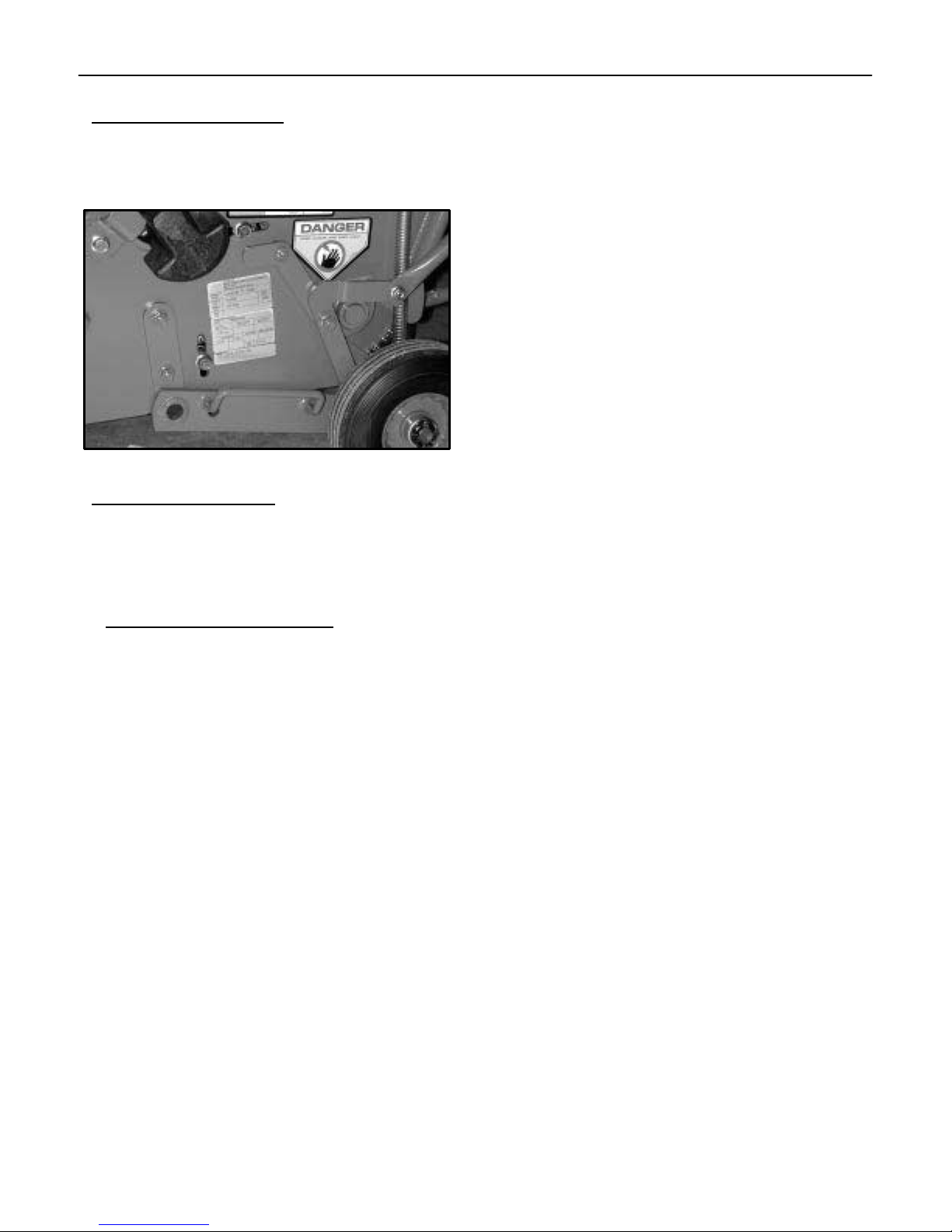
2 IDENTIFICATION
2 IDENTIFICATION
The unit model and serial numbers are printed on the
Nameplate/Identification decal located on the left side of
the aerator frame. See Figure 1.
Figure 1
3 SPECIFICATIONS
Both the Lawnaire IV and V models are available with a
Briggs & Stratton engine or a Honda engine. All other
specifications are identical for each model in the same
product line.
3.1 LAWNAIRE IV
Dimensions:
Width 28” (711 mm). . . . . . . . . . . . . . . . . . . . . . . . . . . . .
Length 52.5” (1295 mm). . . . . . . . . . . . . . . . . . . . . . . . .
Length (handle folded) 46” (1168 mm). . . . . . . . . . . . .
Height (transport) 47.5” (1206 mm). . . . . . . . . . . . . . . .
Height (handle folded) 30” (762 mm). . . . . . . . . . . . . . .
Net Weight:
Dry, w/o acc. weight 200 lbs. (91 Kg). . . . . . . . . . . . .
Dry, w/ acc. weight 240 lbs. (109 Kg). . . . . . . . . . . . .
With water tank full
and acc. weight 280 lbs. (127 Kg). . . . . . . . . . . . . . . .
Engines:
Model 544908
Honda, 4.0 h.p., 4 cycle
Model GX120K1HX. . . . . . . . . . . . . . . . . . . . . . . . . . . . .
Starter Recoil, on/off switch. . . . . . . . . . . . . . . . . . . . . .
Governor 3600 RPM, no load. . . . . . . . . . . . . . . . . . . . .
Idle Speed 1400 ± 100 RPM. . . . . . . . . . . . . . . . . . . . . .
Fuel Tank .66 gal. (2.5 L). . . . . . . . . . . . . . . . . . . . . . .
Gear Reduction 6 to 1. . . . . . . . . . . . . . . . . . . . . . . . . . .
Model 544909
Briggs & Stratton 3.5 h.p., 4 cycle
Model #093452, Type 0141, Trim .01. . . . . . . . . . . . . .
Starter Recoil, on/off switch. . . . . . . . . . . . . . . . . . . . . .
Governor 3200 RPM ± 100 RPM, no load. . . . . . . . . .
Idle Speed 2000 RPM. . . . . . . . . . . . . . . . . . . . . . . . . . .
Fuel Tank 4 qt. (3.8 L). . . . . . . . . . . . . . . . . . . . . . . . . .
Gear Reduction 6 to 1. . . . . . . . . . . . . . . . . . . . . . . . . . .
Drive:
Primary V Belt, 4L section. . . . . . . . . . . . . . . . . . . . . . .
Secondary #40 plated roller chain. . . . . . . . . . . . . . . . .
Wheels:
Front 11” (279 mm) Dia. water tank. . . . . . . . . . . . . . .
5.2 gal. (19.7 L) max. capacity
Rear 8 x 2.50 semi-pneumatic tires. . . . . . . . . . . . . . .
with 3/4” ball bearings
Aeration:
Tines 3/4” (19 mm) formed from .08” hardened . . . .
chrome molybdenum alloy steel, 30 per unit
Penetration Depth 2 3/4” (70 mm) max.. . . . . . . . . . .
Swath Width 19” (483 mm). . . . . . . . . . . . . . . . . . . . . .
Hole Pattern 3 3/4” x 7” (95 x 178 mm) on center. . .
Production Up to 28,975 sq. ft. / hour. . . . . . . . . . . . . .
Speed:
Transport up to 320 f.p.m. (97.5 M.p.m.). . . . . . . . . . .
Aerate up to 305 f.p.m. (93 M.p.m.). . . . . . . . . . . . . . .
2
Page 5

SPECIFICATIONS 3
3.2 LAWNAIRE V
Dimensions:
Width 35.5” (902 mm). . . . . . . . . . . . . . . . . . . . . . . . . . .
Length 52.5” (1333.5 mm). . . . . . . . . . . . . . . . . . . . . . .
Length (handle folded) 46.0” (1168 mm). . . . . . . . . . .
Height (transport) 47.5” (1206 mm). . . . . . . . . . . . . . . .
Net Weight:
Dry, w/o acc. weight 228 lbs. (103 Kg). . . . . . . . . . . .
Dry, w/ acc. weight 266 lbs. (122 Kg). . . . . . . . . . . . .
With water tank full
and acc. weight 330 lbs. (149 Kg). . . . . . . . . . . . . . . .
Speed:
Transport up to 320 f.p.m. (97.5 M.p.m.). . . . . . . . . . .
Aerate up to 305 f.p.m. (93 M.p.m.). . . . . . . . . . . . . . .
Engines:
Model 544910
Honda, 4.0 h.p., 4 cycle
Model GX120K1HX. . . . . . . . . . . . . . . . . . . . . . . . . . . . .
Starter Recoil, on/off switch. . . . . . . . . . . . . . . . . . . . . .
Governor 3600 RPM, no load. . . . . . . . . . . . . . . . . . . . .
Idle Speed 1400 ± 100 RPM. . . . . . . . . . . . . . . . . . . . . .
Fuel Tank .66 gal. (2.5 L). . . . . . . . . . . . . . . . . . . . . . . .
Gear Reduction 6 to 1. . . . . . . . . . . . . . . . . . . . . . . . . . .
Model 544911
Briggs & Stratton 3.5 h.p., 4 cycle
Model #093452, Type 0141, Trim .01. . . . . . . . . . . . . .
Starter Recoil, on/off switch. . . . . . . . . . . . . . . . . . . . . .
Governor 3200 RPM ± 100 RPM, no load. . . . . . . . . .
Idle Speed 2000 RPM. . . . . . . . . . . . . . . . . . . . . . . . . . .
Fuel Tank 4 qt. (3.8 L). . . . . . . . . . . . . . . . . . . . . . . . . .
Gear Reduction 6 to 1. . . . . . . . . . . . . . . . . . . . . . . . . . .
Drive:
Primary V Belt, 4L section. . . . . . . . . . . . . . . . . . . . . . .
Secondary #40 plated roller chain. . . . . . . . . . . . . . . . .
Wheels:
Front 11” (279 mm) Dia. water tank. . . . . . . . . . . . . . .
7.9 gal. (29.9 L) max. capacity
Rear 8 x 2.50 semi-pneumatic tires. . . . . . . . . . . . . . .
and 3/4” ball bearings
Aeration:
Tines 3/4” (19mm) formed from .08” hardened . . . . .
chrome molybdenum alloy steel, 42 per unit
Penetration Depth 2 3/4” (70 mm) max.. . . . . . . . . . .
Swath Width 26 1/2” (673 mm). . . . . . . . . . . . . . . . . .
Hole Pattern 3 3/4” x 7” (95 x 178 mm) on center. . .
Production Up to 40,400 sq. ft. / hour. . . . . . . . . . . . .
3
Page 6
4 OPERATION AND SAFETY DECALS
4 OPERATION AND SAFETY DECALS
Following are the Operational and Safety decals that
appear on the Lawnaire IV and Lawnaire V aerators.
Familiarize yourself with these as it is important to be
aware of their presence and their meaning.
BEFORE AERATING
1. READ OPERATOR’S
MANUAL.
2. PLACE WEIGHTS IN BODY,
SECURE WITH LATCH.
3. IF ADDITIONAL WEIGHT
IS REQUIRED FILL
WATER TANK.
4. TRANSPORT WHEELS MUST
BE IN THE ’DOWN’
POSITION EXCEPT WHEN
OVER AREA TO BE
AERATED.
LOADING AND TRANSPORT
1. REMOVE WEIGHTS FROM
BODY.
2. DRAIN WATER TANK.
OPERATING INSTRUCTIONS
TO AERATE
1. START ENGINE & ADJUST
THROTTLE.
2. LIFT TRANSPORT WHEELS
BY PUSHING LIFT LEVER.
3. PUSH HANDLE DOWN TO
ELEVATE WATER TANK 2
TO 3 INCHES.
4. PULL CLUTCH LEVER TO
HANDLE.
5. TO STOP AERATING,
RELEASE CLUTCH LEVER.
6. TO TURN, LIFT TINES
FROM GROUND AND PIVOT
ON WATER TANK.
7. FOR REVERSE, LOWER
TRANSPORT WHEELS AND
PULL BACKWARDS.
2703117
Operating Instructions
This decal can be found on top of the handle
bar assembly. It lists steps required prior to
aerating and instructions for loading and transporting and aerating.
HANDLE MUST BE LOCKED IN
PLACE BEFORE AERA TINGCAUTION
Handle Warning – LawnAire IV Only
This decal is found on the lower end of the handle
bars. It informs the operator that the folding handle bars need to be securely locked in place prior
to aerating.
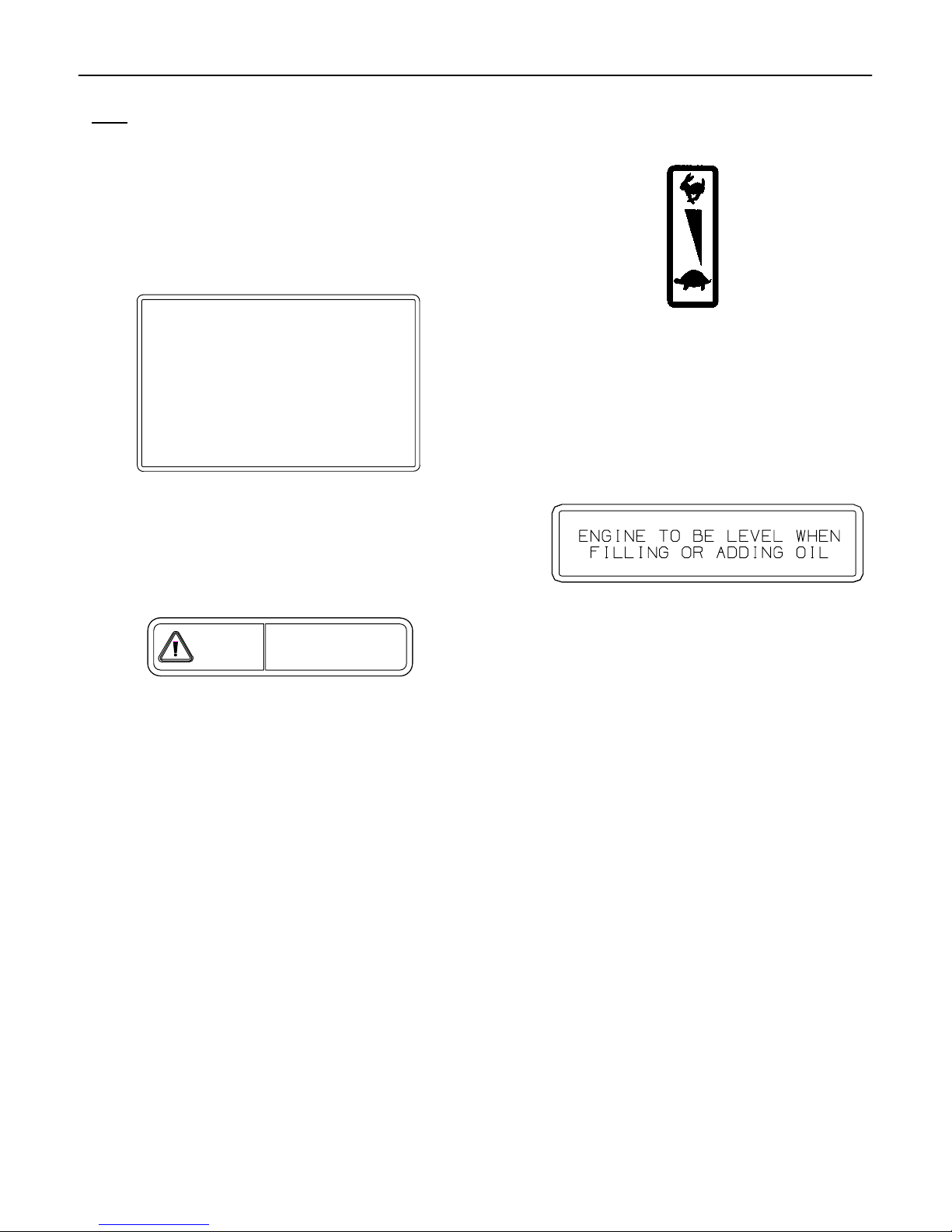
Throttle Control
This decal is found on the handle bar next to the
engine throttle control. It tells the operator which
direction to move the engine throttle for the
desired engine speed. The throttle control decal
uses the turtle to represent slower engine speeds;
the rabbit represents faster engine speeds.
Engine Oil Level
This decal is located on the main frame, in front
of the engine. It tells the operator to have the
engine level prior to checking the oil level.
4
Page 7

WARNING HANDS IN MOVING
COMPONENTS
OPERATION AND SAFETY DECALS 4
This decal is located on the main frame and provides
the operator with three message warnings:
(1) The symbol on the left shows the possible result
of working on machinery with safety shields
removed. Hands and fingers may become
entangled in belts. DO NOT operate the unit without
safety shields in place.
(2) The center symbols warn the operator and/or
bystanders to keep hands out of moving components.
(3) The symbols on the right instruct the operator to
read the service section of the operator’s manual.
Disable the spark plug wire before performing any
service or maintenance on the unit.
DANGER HANDS AND FEET
This decal is located on the main frame and informs
the operator of areas which are capable of serious
injury.
The symbol shows fingers being cut or severed. DO
NOT place hands, feet, fingers or toes under aerator
while operating the unit.
5
Page 8
5 SETUP
5 SETUP
Unless otherwise noted, the information in the following
sections applies to both Lawnaire IV and V models.
5.1 UNPACKING THE AERATOR
Unpacking the aerator entails securing the handle and
rolling the unit off the shipping pallet.
!
WARNING
Banding is under tension and may snap back
when cut. Wear eye protection and stay clear
when cutting the band.
Figure 3
2. Pull up on the transport lift handle to raise the aerator
to the transport position. See Figure 8. Carefully roll
the unit off the pallet.
FOR ALL MODELS
1. Cut the banding securing the aerator to the pallet.
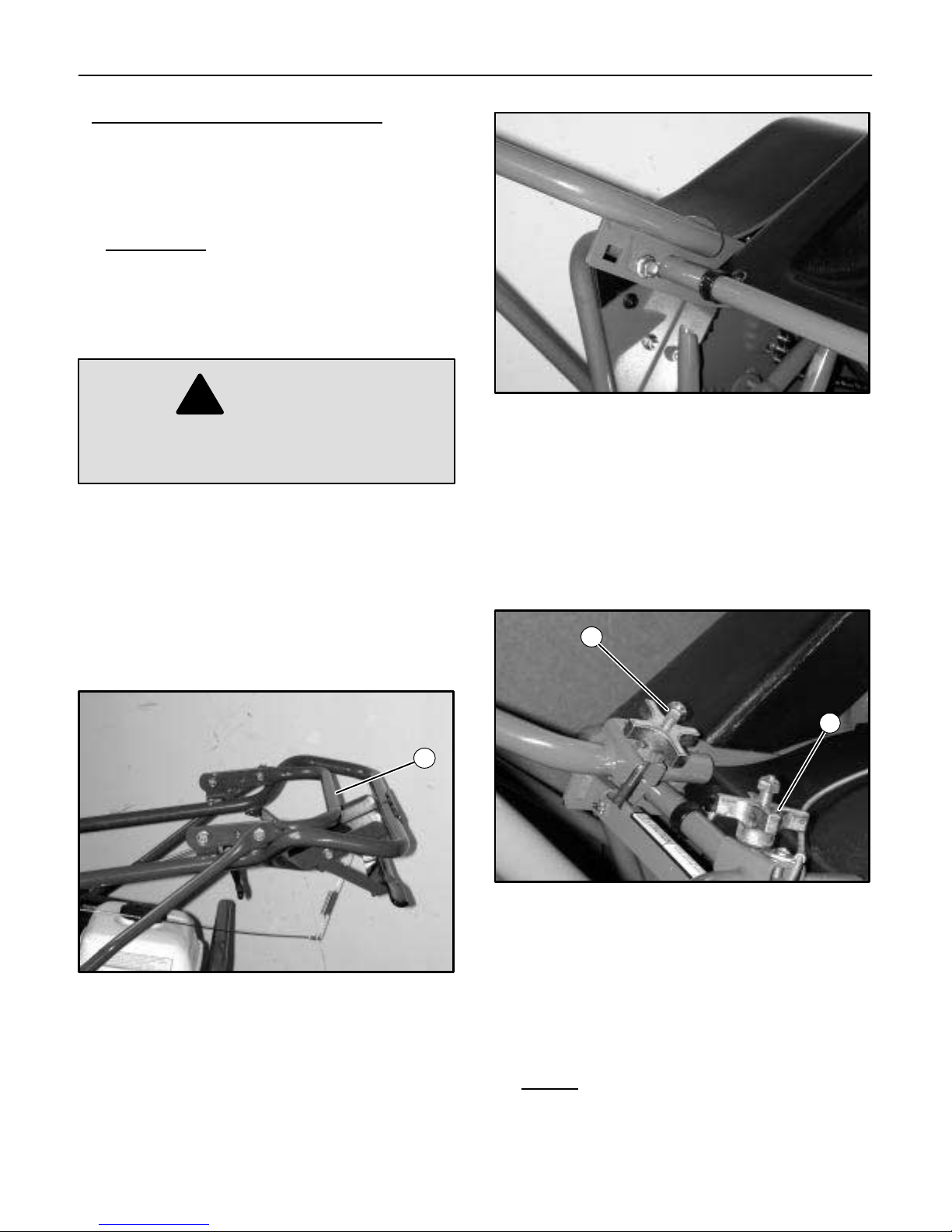
2. Unfold the handle by pulling on the transport lift
handle. See Figure 2.
1
FOR LAWNAIRE IV MODELS
1. Flip the handle locking knobs up into position over
the handle bracket and tighten. HAND TIGHTEN
ONLY! See Figure 4.
1
1
Figure 4
1. Handle Locking Knobs
2. Pull up on the transport lift handle to raise the aerator
to the transport position. See Figure 8. Carefully roll
the unit off the pallet.
Figure 2
1. Transport Lift Handle
FOR LAWNAIRE V MODELS
1. Bolt the handle in place, as shown in Figure 3.
6
NOTE:
If the folding handle will not be used, bolt the
handle in place. See instructions in the
preceding section,
For Lawnaire V Models
.
5.2 CHECKING THE CLUTCH CABLE
The clutch cable is adjusted prior to shipping; however, it
should be checked before the unit is put into service.
Page 9
SETUP 5
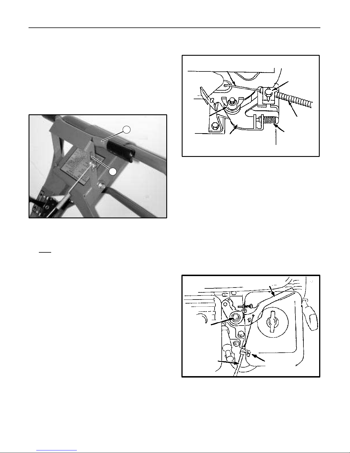
1. Pull the clutch control handle back and down and
make sure the idler engages the belt. See Figure 5.
2. Release the clutch control handle and make sure the
belt disengages completely.
3. If adjustment is necessary, loosen the nut on the
clutch spring hardware and adjust its position in the
slot of the clutch lever. See Figure 5.
NOTE:
Spring extension should not exceed .25 inch.
1
2
5. Tighten the casing clamp screw.
WIRE
THROTTLE
FRICTION
NUT
THROTTLE
CONTROL
CASING
CLAMP
SCREW
CASING
THROTTLE
STOP
SCREW
Figure 6
FOR MODELS WITH HONDA ENGINE
Refer to the following steps and Figure 7.
1. Loosen the throttle lever friction nut enough to allow
free movement of the throttle lever.
Figure 5
1. Clutch Control Handle
2. Adjustment Slot
5.3 CHECKING THE THROTTLE CABLE
The throttle cable is adjusted prior to shipping; however,
it should be checked before the unit is put into service.
The throttle control should freely move in a full range of
motion forward and backward. If necessary, the throttle
cable can be adjusted as follows:
FOR MODELS WITH BRIGGS & STRATTON ENGINE
Refer to the following steps and Figure 6.
1. Loosen the throttle friction wing nut to allow free
movement of the throttle control.
2. Loosen the casing clamp screw on the control plate.
3. Push the throttle lever all the way forward.
4. Push the throttle cable sleeve up through the cable
clamp until fully advanced.
2. Loosen the throttle cable clamp.
3. Push the throttle lever all the way forward.
4. Push the throttle cable sleeve up through the cable
clamp until fully advanced.
5. Tighten the cable clamp securely.
THROTTLE
LEVER
THROTTLE
LEVER
FRICTION NUT
THROTTLE
CABLE
THROTTLE
CABLE
CLAMP
Figure 7
7
Page 10

5 SETUP
5.4 INITIAL BELT SEATING AND
ADJUSTMENT
Proper tensioning of V-belts is the single most important
factor necesssary for long, satisfactory operation. Too
little tension will result in slippage, causing rapid belt and
pulley wear. Too much tension can result in excessive
stress on belts, bearings, and shafts; reduced efficiency;
and operator fatigue due to excessive force required to
hold the bail closed.
1. Operate the drive a few minutes to seat the belts in
the sheave grooves. Observe the operation of the
drive under its highest load condition (usually
starting).
2. Check the tension on a new drive serveral times
during the first 24 hours of opertion.
3. Keep the drive free of foreign material which might
cause slippage or damage to the belt and sheave
surfaces.
4. If a V-belt slips, it is too loose. NEVER apply belt
dressing, as this will damage the belt and cause
early failure.
5. Make sure pulleys stay in proper alignment.
Misaligned pulleys can result in belt rolling in the
pulley groove causing belt damage or breakage.
8
Page 11

CONTROLS 6
6 CONTROLS
6.1 HANDLE CONTROLS
Transport Lift Handle
Pushing down on the handle lowers the tines for aerating.
Pulling the handle up raises the tines so the aerator can
be moved or transported without incurring damage to the
unit or the turf. See Figure 8.
Clutch Control Handle
Engages the belt tightener clutch. Pulling back on the
handle engages the clutch; releasing the handle
disengages the clutch. See Figure 8.
!
WARNING
Releasing the clutch on an incline will cause
freewheeling, which will allow the unit to roll
down the incline.
Throttle Control
Briggs & Stratton Engine Controls
The engine is equipped with an On/Off switch, a choke
control and a fuel shut-off valve. The On/Off switch must
be in the “ON” position for the engine to be started.
Turning the On/Off switch to the “OFF” position will stop
the engine. Using the choke control will help start a cold
engine. After the engine starts, adjust the choke for best
running results. Once the engine warms up, the choke
should not be needed. Refer to Figures 9 and 10.
2
1
The throttle control adjusts the engine speed. Pushing
the control forward increases the speed; pulling the
control back reduces the speed. See Figure 8.
2
1
3
Figure 8
1. Transport Lift Handle
2. Clutch Control Handle
3. Throttle Control
Figure 9
1. Choke Control
2. Fuel Shut-off valve
1
Figure 10
1. On/Off Switch
6.2 ENGINE CONTROLS
The Lawnaire IV & V are available with either a 3.5 HP
Briggs & Stratton engine or a 4 HP Honda engine.
9
Page 12
6 CONTROLS
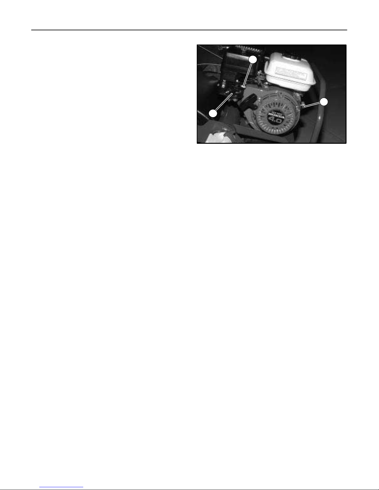
Honda Engine Controls
The engine is equipped with a choke, a fuel valve and an
On/Off switch. The fuel valve and the On/Off switch must
both be in the “ON” position to start the engine. Turn the
On/Off switch to “OFF” to stop the engine. Using the
choke will help start a cold engine. After the engine
starts, adjust the choke for best running results. Once the
engine warms, the choke should not be needed. Refer to
Figure 11.
1
3
2
Figure 11
1. Choke
2. Fuel Valve
3. On/Off Switch
10
Page 13
OPERATION 7
7 OPERATION
7.1 PRE-OPERATION CHECK
1. Visually check all moving parts and all fasteners. If
loose or broken, tighten or replace. Check for broken
or bent tines; replace if necessary.
2. Check the engine crankcase and gear reduction
case oil levels with the engine resting in a level
position. Add oil if necessary.
3. Follow the engine manufacturer’s recommendations
for the correct type and amount of oil. Fill the fuel
tank according to the engine manufacturer’s
specifications.
!
WARNING
Gasoline is extremely flammable and highly
explosive under certain conditions. Always
stop the engine and do not smoke or allow
open flames or sparks when refueling. BE
SURE to reinstall fuel cap after refueling.
NEVER start or run the engine inside where
exhaust fumes can collect. Carbon monoxide
present in the exhaust is an odorless and
deadly gas.
DO NOT operate equipment without shields in
place. DO NOT make adjustments or perform
any maintenance while the engine is running.
Before operating, check the area and remove
any objects which may present a safety hazard
or damage the equipment.
This unit is not designed to be used on steep
slopes. To prevent injury and/or damage to
equipment, use extreme caution when operating near terraces or hilly terrain. Travel up and
down slopes at a 45
to prevent unit from tipping over. DO NOT
release clutch handle on a slope; this will
cause freewheeling, allowing the unit to roll
down the slope.
7.2 AERATING
NOTE:
For best performance and maximum tine
penetration, the lawn should be thoroughly
watered the day before aeration.
o
angle rather than across,
1. Rotate the water drum on the front of the unit until the
filler plug is positioned at the top. Remove the plug,
fill the drum with water and replace the plug. See
Figure 12.
1
Figure 12
1. Water Drum Filler Plug
2. Move the engine On/Off switch to the “ON” position
and then pull the recoil starter and choke as required
to start the engine.
3. Lift the transport lift handle if necessary to make sure
the tines are not touching the ground, advance the
throttle, slowly pull back on the clutch handle control
and transport the aerator to the work area.
NOTE:
4. Upon reaching the work area, release the clutch
5. Push down on the transport lift handle, lowering the
6. Pull back slowly on the clutch control handle to start
NOTE:
7. At the end of each aerating pass, release the clutch
8. When finished aerating, lift up on the transport lift
9. Drain the water drum when finished with aerating.
Never cross hard objects or surfaces (such as
sidewalks, driveways, stepping stones, etc.)
with tines in the down position.
control handle and adjust the throttle speed for
aerating.
aerating tines to the turf.
aerating.
For maximum tine penetration into turf, apply
downward pressure on the handle, until drum is
off the ground.
control handle, lift up on the handle assembly and
pivot the unit on the water drum. Resume aerating.
handle to move the unit into transport position.
11
Page 14
8 SERVICE
8 SERVICE
!
WARNING
When replacement parts are required, use
genuine RYAN parts or parts with equivalent
characteristics, including type, strength and
material. Failure to do so may result in product
malfunction and possible injury to the
operator and/or bystanders.
Any warning decal that becomes illegible
should be replaced immediately.
Do not operate equipment without shields in
place.
Do not make any adjustments or perform any
maintenance while the engine is running.
1. Thoroughly clean all tines inside and out when
aerating is completed and apply a light coat of oil to
prevent rust on tines.
6. Keep the roller chain clean and in proper running
order. Lubricate using Lubriplate #13563, available
as Part No. 523248.
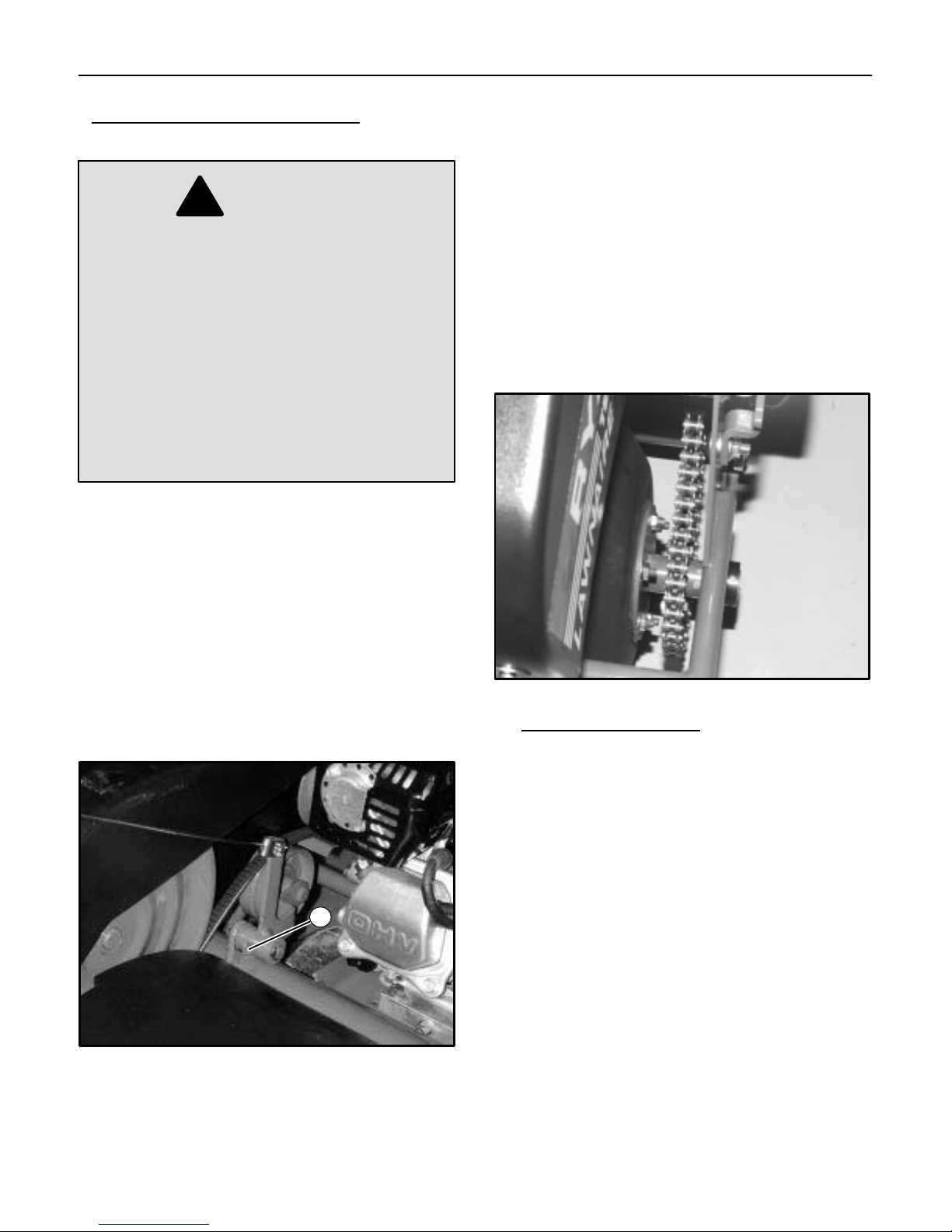
7. Check the roller chain for tightness and wear . Adjust
idler sprockets if necessary by loosening the nut and
screw holding the idler sprocket to the frame and
then sliding the sprocket in the slot to the desired
position. Tighten hardware.
NOTE:
Excessive roller chain tightness will shorten the
life of the bearings. The chain should have
movement of 1/8″ to 1/4″ (3 mm to 6 mm)
deflection at the center point between the upper
idler and drum sprockets. See Figure 14.
2. Check the engine and gear reduction case oil levels
with the engine resting in a level position.
3. Inspect the air filter element and replace it if
necessary.
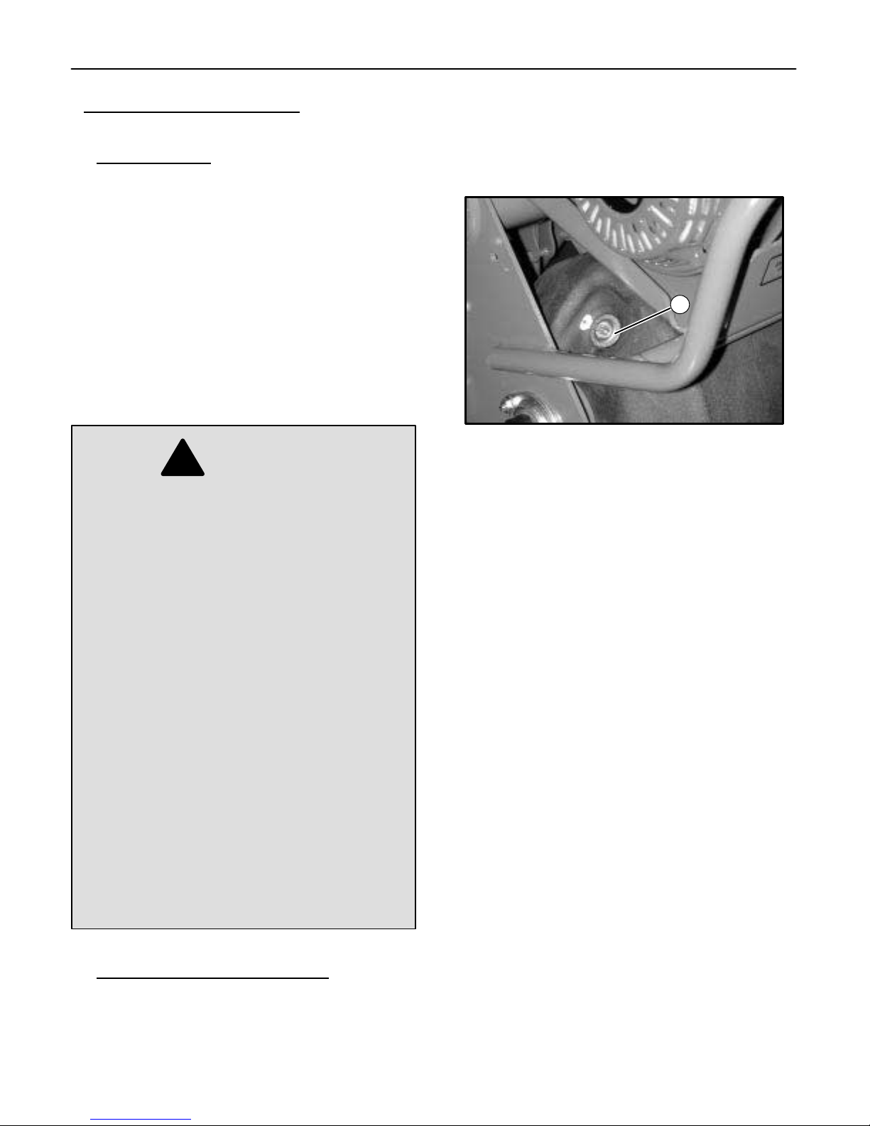
4. Lubricate the clutch pivot prior to each aerating
season or as needed. See Figure 13.
1
Figure 14
8.1 TOUCH UP PAINT
Ransomes Green (medium green)
16 oz. (0.5L) spray order no. 838140. . . . . . . . . . . . . .
1 qt. (0.95L) can order no. 838141. . . . . . . . . . . . . . . .
Figure 13
1. Clutch Pivot Lube Fitting
5. Keep the drive belt free of oil and dirt and replace if
worn or damaged.
12
Page 15

STORAGE 9
9 STORAGE INSTRUCTIONS
!
WARNING
To prevent possible explosion or ignition of
vaporized fuel, do not store equipment with
fuel in tank or carburetor in an enclosure with
open flame (for example, a furnace or water
heater pilot light).
Before the equipment is put into storage for any period
exceeding 30 days, the following steps should be taken:
1. Drain all fuel from the fuel tank and fuel lines.
2. Start the engine and run until all the fuel is used from
the carburetor float bowl.
3. While the engine is still warm, drain the crankcase oil
and replace with the proper weight oil corresponding
to the season the equipment will next be used.
4. Remove the spark plug and squirt a small amount of
engine oil into the cylinder. Turn the engine over a
few times to distribute the oil.
5. Drain the water drum.
NOTE:
6. Lubricate the clutch pivot fitting.
To put the equipment into service after an extended
period of storage:
1. Check for loose parts and tighten if necessary.
2. Check for cracked or broken tines and replace as
3. Fill the fuel tank.
4. Check the engine and gear reduction case oil levels
5. Start the engine.
6. Check for fuel leaks.
7. Check clutch control operation to make sure the unit
Always drain the water drum for winter storage.
Freezing water can rupture the drum.
necessary.
with the engine in a level position.
stops when the clutch control is released.
13
Page 16

10 TRANSPORTING
10 TRANSPORTING
If a tote trailer will be used to transport the unit, the two
cast weights must be removed from the aerator frame
and a locking shaft installed in their place.
Removing the cast weights and draining the water drum
will decrease the weight for easier loading on a vehicle o r
trailer.
To remove the weights, pull up on the latch securing the
weights and slide the weights out. See Figure 15.
1
2
REMOVABLE TRANSPORT WHEELS
The rear wheels of the Lawnaire V are removable for
transporting the aerator through fence gates.
With the wheels removed the Lawnaire V will pass
through a 32 inch opening.
With the engine of f, lower the aerator so that the tines are
on the ground and the wheels are off the ground.
Remove hair p i n s f r o m t h e a x l e s . Slide wheels and axles
out of transport frame. See Figure 16.
Lift up on the aerator handle so the tines are off the
ground. With the tines off the ground, push the aerator
through the gate on the front drum. Once on the other
side of the gate, reinstall the wheels.
Figure 15
1. Latch
2. Weights
!
CAUTION
Use caution when removing the cast weights.
Each weight is approximately 22 lbs.
NOTE:
Be sure to close the fuel shut off valve before
transporting the unit.
1
Figure 16
1. Hair Pin For Wheel Removal
14
Page 17

TORQUE CHART 11
TORQUE SPECIFICATIONS
HEX HEAD CAP SCREWS
The torque values shown should be used as a general guideline when specific torque values are not given.
U.S. Standard Hardware
Shank Size (Diameter in inches, fine or coarse thread)
Grade
1/4 5/16 3/8 7/16 1/2 9/16 5/8 3/4 7/8 1 1 1/8
SAE
grade
5 *
SAE
grade
8 **
Flangelock
Screw w/
Flangelock
Nut
* Grade 5 marking – Minimum commercial quality (Lower quality not recommended).
** Grade 8 marking –
ft.-lb. 9 18 31 50 75 110 150 250 378 583 782
N·m 12 24 42 68 102 150 203 339 513 790 1060
ft.-lb. 13 28 46 75 115 165 225 370 591 893 1410
N·m 18 38 62 108 156 224 305 502 801 1211 1912
ft.-lb. 24 40
N·m 33 54
Metric Standard Hardware
Shank Size (Diameter in millimeters, fine or coarse thread)
Grade
Grade
8.8*
N·m 2 4 7 11 18 32 58 94 144 190 260 368 470 707
ft.-lb. 1.5 3 5.2 8.2 13.5 24 43.5 70.5 108 142 195 276 353 530
M4 M5 M6 M7 M8 M10 M12 M14 M16 M18 M20 M22 M24 M27
Grade
10.9**
Grade
12.9 ***
* Grade 8.8 marking – ** Grade 10.9 marking – *** Grade 12.9 marking –
N·m 3 6 10 16 25 47 83 133 196 269 366 520 664 996
ft.-lb. 2.2 4.5 7.5 12 18.8 35.2 62.2 100 147 202 275 390 498 747
N·m 3.6 7 11 20 29 58 100 159 235 323 440 628 794 1205
ft.-lb. 2.7 5.2 8.2 15 21.8 43.5 75 119 176 242 330 471 596 904
8.8 10.9 12.9
15
Page 18

NOTES
16
Page 19

ILLUSTRATED PARTS 12
PARTS
SECTION
17
Page 20

12.1 LAWNAIRE IV DRUM GROUP
5
13
11
9
7
11
3
10
8
12
11
Ref.
No.
1 2702741.2 Plate, flange 1. . . . . . . . . . . . . . . . . . . . . . . . . . . . . . . .
2 2703102.2 Drive AY 1. . . . . . . . . . . . . . . . . . . . . . . . . . . . . . . . . . .
3 2703157.2 Sprocket, 30T, .50P 1. . . . . . . . . . . . . . . . . . . . . . . . .
4 2703508 Flange, bearing 2.04 I.D. 4. . . . . . . . . . . . . . . . . . . . .
5 2703783 Drum, water 1. . . . . . . . . . . . . . . . . . . . . . . . . . . . . . . .
6 522480 Gasket, 4.50 dia. 1. . . . . . . . . . . . . . . . . . . . . . . . . . . .
7 522481 Gasket, 3.00 dia. 1. . . . . . . . . . . . . . . . . . . . . . . . . . . .
8 545786 Bearing Assembly 2. . . . . . . . . . . . . . . . . . . . . . . . . . .
9 545887 Ring AY, split 2. . . . . . . . . . . . . . . . . . . . . . . . . . . . . . .
10 548604 Screw, 5/16-18 x 3/4 3. . . . . . . . . . . . . . . . . . . . . . . . .
11 548911 Nut, 5/16-18 19. . . . . . . . . . . . . . . . . . . . . . . . . . . . . . .
12 800557 Bolt, carriage, 5/16-18 x 3/4 4. . . . . . . . . . . . . . . . . .
13 821274 Plug, drain 1. . . . . . . . . . . . . . . . . . . . . . . . . . . . . . . . .
Part
No.
4
Description Notes
6
11
12
No.
Req’d
1
2
8
4
11
18
Page 21

LAWNAIRE IV TINE WHEEL GROUP 12.2
10
8
7
2
6
9
5
7
3
1
4
7
5
Ref.
No.
1 2702742.2 Tine Wheel AY 1. . . . . . . . . . . . . . . . . . . . . . . . . . . . . .
2 2703160.2 Sprocket, 42T, .50P 1. . . . . . . . . . . . . . . . . . . . . . . . .
3 2703508 Flange, bearing 2.04 I.D. 4. . . . . . . . . . . . . . . . . . . . .
4 522361 Tine, coring, 3/4 30. . . . . . . . . . . . . . . . . . . . . . . . . . . .
5 545786 Bearing Assembly 2. . . . . . . . . . . . . . . . . . . . . . . . . . .
6 548604 Screw, 5/16-18 x 3/4 3. . . . . . . . . . . . . . . . . . . . . . . . .
7 548911 Nut, 5/16-18 7. . . . . . . . . . . . . . . . . . . . . . . . . . . . . . . .
8 800290 Nut, centerlock, 5/16-18 60. . . . . . . . . . . . . . . . . . . . .
9 800557 Bolt, carriage, 5/16-18 x 3/4 4. . . . . . . . . . . . . . . . . .
10 800606 Bolt, carriage, 5/16-18 x 1 1/2 60. . . . . . . . . . . . . . . .
Part
No.
Description Notes
9
No.
Req’d
3
19
Page 22

12.3 LAWNAIRE IV HANDLE GROUP
11
23
5
10
17
3
17
24
19
2
20
21
12
8
1
22
18
6
26
28
27
9
14
7
25
18
9
13
4
15
29
30
16
28
8
12
REF:
TINE COVER
17
20
Page 23

LAWNAIRE IV HANDLE GROUP 12.3
Ref.
No.
1 103867 Washer, Flat, 5/16 1. . . . . . . . . . . . . . . . . . . . . . . . . . .
2 2703058.2 Handle assembly 1. . . . . . . . . . . . . . . . . . . . . . . . . . . .
3 2703059.2 Handle, height adjustment 1. . . . . . . . . . . . . . . . . . . .
4 2703067.2 Tube, control 2. . . . . . . . . . . . . . . . . . . . . . . . . . . . . . .
5 2703070.2 Bail assembly 1. . . . . . . . . . . . . . . . . . . . . . . . . . . . . . .
6 2703185 Control assembly, throttle, 43” 1. . . . . . . . . . . . . . . .
7 306501 Screw, 5/16 -18 x 1 1. . . . . . . . . . . . . . . . . . . . . . . . . .
8 517226 Bushing 2. . . . . . . . . . . . . . . . . . . . . . . . . . . . . . . . . . . .
9 518438 Bushing, stl, .391ID x .500OD x .35 2. . . . . . . . . . . .
10 521679 Bushing 1. . . . . . . . . . . . . . . . . . . . . . . . . . . . . . . . . . . .
11 523139 Grip, handle 1. . . . . . . . . . . . . . . . . . . . . . . . . . . . . . . .
12 524643 Bearing, split 2. . . . . . . . . . . . . . . . . . . . . . . . . . . . . . .
13 548477 Washer, Flat, 41/64 1. . . . . . . . . . . . . . . . . . . . . . . . . .
14 548905 Screw, 3/8 -16 x 1 1. . . . . . . . . . . . . . . . . . . . . . . . . . .
15 800073 Carriage bolt, 3/8-16 x 1.25 1. . . . . . . . . . . . . . . . . . .
16 800557 Carriage bolt, 5/16-18 x 3/4 1. . . . . . . . . . . . . . . . . . .
17 800697 Nut, 5/16-18, crownlock 3. . . . . . . . . . . . . . . . . . . . . .
18 800698 Nut, 3/8-16, crownlock 2. . . . . . . . . . . . . . . . . . . . . . .
19 800710 Screw, 5/16-18 x 1 1. . . . . . . . . . . . . . . . . . . . . . . . . .
20 819195 Screw, tapping, #8-18 x 1/2 2. . . . . . . . . . . . . . . . . . .
21 822474 Spacer, 3/8 x 3/4 x 1/2 1. . . . . . . . . . . . . . . . . . . . . . .
22 830165 Bushing 1. . . . . . . . . . . . . . . . . . . . . . . . . . . . . . . . . . . .
23 548910 Nut, 1/4 - 20 2. . . . . . . . . . . . . . . . . . . . . . . . . . . . . . . .
24 800026 Screw, 1/4 - 20 x 3/4 1. . . . . . . . . . . . . . . . . . . . . . . . .
25 809069 Clip 1. . . . . . . . . . . . . . . . . . . . . . . . . . . . . . . . . . . . . . .
26 800277 Screw, 1/4-20 x 5/8 1 Honda engine only.. . . . . . . . . . . . . . . . . . . . . . . . . .
27 800169 Nut, 1/4-20, speed 1 Honda engine only.. . . . . . . . . . . . . . . . . . . . . . . . . .
28 812445 Clamp 1. . . . . . . . . . . . . . . . . . . . . . . . . . . . . . . . . . . . .
29 819195 Screw, #8-18 1/2, tapping 1 Briggs & Stratton engine only.. . . . . . . . . . . . . . . . . . . .
30 308089 Washer, #10 1 Briggs & Stratton engine only.. . . . . . . . . . . . . . . . . . . . . . . . . . . . . . . .
Part
No.
Description Notes
No.
Req’d
21
Page 24

12.4 LAWNAIRE IV FRAME GROUP
20
22
17
24
16
6
23
13
24
16
17
12
18
22
3
5
9
27
7
3
28
13
14
1
19
11
10
25
29
1
8
22
15
20
22
26
21
4
Page 25

LAWNAIRE IV FRAME GROUP 12.4
Ref.
No.
1 120219 Pin, cotter, .09 3. . . . . . . . . . . . . . . . . . . . . . . . . . . . . .
2 2702248 Screw, 3/8-16 x 1 3/4 1. . . . . . . . . . . . . . . . . . . . . . . .
3 2702738 Shaft, jack 1. . . . . . . . . . . . . . . . . . . . . . . . . . . . . . . . . .
4 2702877.2 Frame assembly, transport 1. . . . . . . . . . . . . . . . . . .
5 841261 Sprocket, 16T, 1/2P 1. . . . . . . . . . . . . . . . . . . . . . . . .
6 2703341.2 Bellcrank assembly, idler 1. . . . . . . . . . . . . . . . . . . . .
7 2703519 Bushing, shoulder 21/64 x 3/4 x 51/64 2. . . . . . . . .
8 2703756.2 Link assembly, lower left 1. . . . . . . . . . . . . . . . . . . . .
9 2703757.2 Link assembly, upper left 1. . . . . . . . . . . . . . . . . . . . .
10 2703758.2 Link assembly, lower right 1. . . . . . . . . . . . . . . . . . . .
11 2703759.2 Link assembly, upper right 1. . . . . . . . . . . . . . . . . . . .
12 306367 Key, woodruff, 3/16 x 3/4 2. . . . . . . . . . . . . . . . . . . . .
13 308091 Washer, flat, 1/2 x 1 1/16 x 3/32 2. . . . . . . . . . . . . . .
14 521609 Pulley, driven 10” 1. . . . . . . . . . . . . . . . . . . . . . . . . . . .
15 521679 Bushing 2. . . . . . . . . . . . . . . . . . . . . . . . . . . . . . . . . . . .
16 521856 Bearing, ball 2. . . . . . . . . . . . . . . . . . . . . . . . . . . . . . . .
17 521857 Collar, brg locking 2. . . . . . . . . . . . . . . . . . . . . . . . . . .
18 548201 Screw, set, 5/16-18 x 5/16 2. . . . . . . . . . . . . . . . . . . .
19 548225 Fitting, grease, 45D 1. . . . . . . . . . . . . . . . . . . . . . . . .
20 548804 Nut, 3/8-16 5. . . . . . . . . . . . . . . . . . . . . . . . . . . . . . . . .
21 548905 Screw, 3/8-16 x 1 4. . . . . . . . . . . . . . . . . . . . . . . . . . .
22 548911 Nut, 5/16-18 6. . . . . . . . . . . . . . . . . . . . . . . . . . . . . . . .
23 548942 Pulley, idler, 3.25 dia. 1. . . . . . . . . . . . . . . . . . . . . . . .
24 548962 Housing, bearing 4. . . . . . . . . . . . . . . . . . . . . . . . . . . .
25 603620 Washer, flat, 3/8 x 1 x 1/8 4. . . . . . . . . . . . . . . . . . . .
26 800073 Bolt, carriage, 3/8-16 x 1 1/4 2. . . . . . . . . . . . . . . . . .
27 800329 Screw, 5/16-18 x 1 1/2 2. . . . . . . . . . . . . . . . . . . . . . .
28 800557 Bolt, carriage, 5/16-18 x 3/4 4. . . . . . . . . . . . . . . . . .
29 800698 Nut, crownlock, 3/8-16 2. . . . . . . . . . . . . . . . . . . . . . .
Part
No.
Description Notes
No.
Req’d
23
Page 26

12.5 LAWNAIRE IV MAIN GROUP
32
27
HONDA ENGINES USE
EXISTING HARDWARE.
B&S ENGINES USE
548898 SCREWS
10
25
35
1
30
14
41
34
6
34
7
34
34
2
36
11
5
29
40
25
26
CRIMP ENDS OF
SPRING AROUND
CABLE END AND
BAIL HARDWARE
SO THAT SPRING
WILL NOT COME
OFF WHEN CABLE
IS LOOSE.
3
12
28
38
16
24
20
21
22
33
13
23
19
43
36
35
42
30
4
39
1
25
34
37
17
30
15
1531
8
USE WASHERS (ITEM 15)
AS NEEDED TO ALIGN
9
CHAIN TO IDLER
SPROCKETS
18
24
Page 27

LAWNAIRE IV MAIN GROUP 12.5
Ref.
No.
1 103867 Washer, flat, 5/16 6. . . . . . . . . . . . . . . . . . . . . . . . . . .
2 120219 Pin, cotter 1. . . . . . . . . . . . . . . . . . . . . . . . . . . . . . . . . .
3 2702958 Wheel, 8 x 2.5 - pneum 2. . . . . . . . . . . . . . . . . . . . . .
4 2703148 Weight 2. . . . . . . . . . . . . . . . . . . . . . . . . . . . . . . . . . . . .
5 4117195 Cable, clutch 1. . . . . . . . . . . . . . . . . . . . . . . . . . . . . . .
6 2703444 Cover, drive 1. . . . . . . . . . . . . . . . . . . . . . . . . . . . . . . .
7 2703445 Cover, tine 1. . . . . . . . . . . . . . . . . . . . . . . . . . . . . . . . .
8 2763611 Chain w/link, #40 1. . . . . . . . . . . . . . . . . . . . . . . . . . . .
9 4113841 •Link, #40 1. . . . . . . . . . . . . . . . . . . . . . . . . . . . . . . . . .
10 2703616.2 Bracket assembly, cover 1. . . . . . . . . . . . . . . . . . . . .
11 2703692 Clip, tube 3. . . . . . . . . . . . . . . . . . . . . . . . . . . . . . . . . .
12 304636 Pin, cotter 2. . . . . . . . . . . . . . . . . . . . . . . . . . . . . . . . . .
13 306372 Pin, cotter 2. . . . . . . . . . . . . . . . . . . . . . . . . . . . . . . . . .
14 306501 Screw, 5/16 x 1 1/2 4. . . . . . . . . . . . . . . . . . . . . . . . . .
15 306981 Washer, flat, 3/8 4. . . . . . . . . . . . . . . . . . . . . . . . . . . .
16 4109880.2 Latch, weight 2. . . . . . . . . . . . . . . . . . . . . . . . . . . . . . .
17 4113746 Spring, extension 2. . . . . . . . . . . . . . . . . . . . . . . . . . . .
18 4113972.2 Cover, chain 1. . . . . . . . . . . . . . . . . . . . . . . . . . . . . . . .
19 4114101 Rod, adjustment 2. . . . . . . . . . . . . . . . . . . . . . . . . . . .
20 4114111 Spring, torsion 2. . . . . . . . . . . . . . . . . . . . . . . . . . . . . .
21 4114319 Belt, kevlar 1. . . . . . . . . . . . . . . . . . . . . . . . . . . . . . . . .
22 4114608 Bushing, shoulder .390 ID X .71 2. . . . . . . . . . . . . . .
23 4115632 Knob, 2 1/2” 2. . . . . . . . . . . . . . . . . . . . . . . . . . . . . . . .
24 521608 Pulley, 4 inch diameter 1. . . . . . . . . . . . . . . . . . . . . . .
25 522516 Mount, isolation 4. . . . . . . . . . . . . . . . . . . . . . . . . . . . .
26 523898 Spring, extension 1. . . . . . . . . . . . . . . . . . . . . . . . . . . .
27 548175 Washer, flat, 1/4 1. . . . . . . . . . . . . . . . . . . . . . . . . . . .
28 548366 Key 1. . . . . . . . . . . . . . . . . . . . . . . . . . . . . . . . . . . . . . .
29 548910 Nut, 1/4 2. . . . . . . . . . . . . . . . . . . . . . . . . . . . . . . . . . . .
30 548911 Nut, 5/16 8. . . . . . . . . . . . . . . . . . . . . . . . . . . . . . . . . . .
31 548960 Sprocket, idler 2. . . . . . . . . . . . . . . . . . . . . . . . . . . . . .
32 800017 Screw, 1/4 1. . . . . . . . . . . . . . . . . . . . . . . . . . . . . . . . . .
33 800531 Nut, crownlock, 3/8 2. . . . . . . . . . . . . . . . . . . . . . . . . .
34 800582 Screw, 1/4 x 3/4 9. . . . . . . . . . . . . . . . . . . . . . . . . . . . .
35 800698 Nut, crown, 3/8 4. . . . . . . . . . . . . . . . . . . . . . . . . . . . .
36 800706 Nut, flange, 5/16 4. . . . . . . . . . . . . . . . . . . . . . . . . . . .
37 800710 Screw, 5/16 2. . . . . . . . . . . . . . . . . . . . . . . . . . . . . . . .
38 800711 Screw, 3/8 -16 x 1.75 2. . . . . . . . . . . . . . . . . . . . . . . .
39 800712 Screw, 3/8 -16 x 2.00 2. . . . . . . . . . . . . . . . . . . . . . . .
40 800862 Screw, 1/4 2. . . . . . . . . . . . . . . . . . . . . . . . . . . . . . . . . .
41 813379 Pin, clevis 1. . . . . . . . . . . . . . . . . . . . . . . . . . . . . . . . . .
42 822474 Spacer, 3/8 x 3/4 2. . . . . . . . . . . . . . . . . . . . . . . . . . . .
43 823225 Pin, clevis 2. . . . . . . . . . . . . . . . . . . . . . . . . . . . . . . . . .
Part
No.
Description Notes
No.
Req’d
25
Page 28

12.6 LAWNAIRE V DRUM GROUP
5
11
13
11
9
7
11
3
10
1
8
2
6
12
11
4
12
8
11
4
26
Page 29

LAWNAIRE V DRUM GROUP 12.6
Ref.
No.
Part
No.
1 2702741.2 Plate, flange 1. . . . . . . . . . . . . . . . . . . . . . . . . . . . . . . .
2 2703108.2 Drive assembly 1. . . . . . . . . . . . . . . . . . . . . . . . . . . . .
3 2703157.2 Sprocket, 30T, .50P 1. . . . . . . . . . . . . . . . . . . . . . . . .
4 2703508 Flange, bearing, 2.04 I.D. 4. . . . . . . . . . . . . . . . . . . .
5 2703785 Drum, water 1. . . . . . . . . . . . . . . . . . . . . . . . . . . . . . . .
6 522480 Gasket, 4.50 dia. 1. . . . . . . . . . . . . . . . . . . . . . . . . . . .
7 522481 Gasket, 3.00 dia. 1. . . . . . . . . . . . . . . . . . . . . . . . . . . .
8 545786 Bearing Assembly 2. . . . . . . . . . . . . . . . . . . . . . . . . . .
9 545887 Ring assembly, split 2. . . . . . . . . . . . . . . . . . . . . . . . .
10 548604 Screw, 5/16-18 x 3/4 3. . . . . . . . . . . . . . . . . . . . . . . . .
11 548911 Nut, 5/16-18 19. . . . . . . . . . . . . . . . . . . . . . . . . . . . . . .
12 800557 Bolt, carriage, 5/16-18 x 3/4 4. . . . . . . . . . . . . . . . . .
13 821274 Plug, drain 1. . . . . . . . . . . . . . . . . . . . . . . . . . . . . . . . .
Description Notes
No.
Req’d
27
Page 30

12.7 LAWNAIRE V TINE WHEEL GROUP
4
10
2
6
5
9
3
7
8
1
5
7
9
7
28
3
Page 31

LAWNAIRE V TINE WHEEL GROUP 12.7
Ref.
No.
1 2703004.2 Tine Wheel AY 1. . . . . . . . . . . . . . . . . . . . . . . . . . . . . .
2 2703160.2 Sprocket, 42T, .50P 1. . . . . . . . . . . . . . . . . . . . . . . . .
3 2703508 Flange, bearing 2.04 I.D. 4. . . . . . . . . . . . . . . . . . . . .
4 522361 Tine, coring, 3/4 42. . . . . . . . . . . . . . . . . . . . . . . . . . . .
5 545786 Bearing Assembly 2. . . . . . . . . . . . . . . . . . . . . . . . . . .
6 548604 Screw, 5/16-18 x 3/4 1. . . . . . . . . . . . . . . . . . . . . . . . .
7 548911 Nut, 5/16-18 3. . . . . . . . . . . . . . . . . . . . . . . . . . . . . . . .
8 800290 Nut, centerlock, 5/16-18 2. . . . . . . . . . . . . . . . . . . . . .
9 800557 Bolt, carriage, 5/16-18 x 3/4 2. . . . . . . . . . . . . . . . . .
10 800606 Bolt, carriage, 5/16-18 x 1 1/2 2. . . . . . . . . . . . . . . . .
Part
No.
Description Notes
No.
Req’d
29
Page 32

12.8 LAWNAIRE V HANDLE GROUP
11
5
17
23
24
19
10
2
3
21
12
17
6
8
20
1
18
22
9
14
7
25
18
9
13
4
15
12
17
30
26
16
27
28
8
REF:
TINE COVER
Page 33

LAWNAIRE V HANDLE GROUP 12.8
Ref.
No.
Part
No.
1 103867 Washer, Flat, 5/16 1. . . . . . . . . . . . . . . . . . . . . . . . . . .
2 2703029.2 Handle assembly 1. . . . . . . . . . . . . . . . . . . . . . . . . . . .
3 2703060.2 Handle, height adjustment 1. . . . . . . . . . . . . . . . . . . .
4 2703067.2 Tube, control 1. . . . . . . . . . . . . . . . . . . . . . . . . . . . . . .
5 2703070.2 Bail assembly 1. . . . . . . . . . . . . . . . . . . . . . . . . . . . . . .
6 2703185 Control assembly, throttle, 43” 1. . . . . . . . . . . . . . . .
7 306501 Screw, 5/16-18 x 1 1. . . . . . . . . . . . . . . . . . . . . . . . . .
8 517226 Bushing 2. . . . . . . . . . . . . . . . . . . . . . . . . . . . . . . . . . . .
9 518438 Bushing, stl, .391 ID x .500 OD x .35 2. . . . . . . . . . .
10 521679 Bushing 1. . . . . . . . . . . . . . . . . . . . . . . . . . . . . . . . . . . .
11 523139 Grip, handle 1. . . . . . . . . . . . . . . . . . . . . . . . . . . . . . . .
12 524643 Bearing, split 2. . . . . . . . . . . . . . . . . . . . . . . . . . . . . . .
13 548477 Washer, Flat 41/64 1. . . . . . . . . . . . . . . . . . . . . . . . . .
14 548905 Screw, 3/8-16 x 1 1. . . . . . . . . . . . . . . . . . . . . . . . . . .
15 800073 Bolt, carriage, 3/8-16 x 1 1/4 1. . . . . . . . . . . . . . . . . .
16 800557 Bolt, carriage, 5/16-18 x 3/4 1. . . . . . . . . . . . . . . . . .
17 800697 Nut, crownlock, 5/16-18 3. . . . . . . . . . . . . . . . . . . . . .
18 800698 Nut, crownlock, 3/8-16 2. . . . . . . . . . . . . . . . . . . . . . .
19 800710 Screw, 5/16-18 x 1 1. . . . . . . . . . . . . . . . . . . . . . . . . .
20 819195 Screw, tapping, #8-18 x 1/2 2. . . . . . . . . . . . . . . . . . .
21 822474 Spacer, 3/8 x 3/4 x 1/2 1. . . . . . . . . . . . . . . . . . . . . . .
22 830165 Bushing 1. . . . . . . . . . . . . . . . . . . . . . . . . . . . . . . . . . . .
23 548910 Nut, 1/4-20 2. . . . . . . . . . . . . . . . . . . . . . . . . . . . . . . . .
24 800026 Screw, 1/4-20 x 3/4 1. . . . . . . . . . . . . . . . . . . . . . . . . .
25 809069 Clip 1. . . . . . . . . . . . . . . . . . . . . . . . . . . . . . . . . . . . . . .
26 819195 Screw, #8-18 1/2, tapping 1 Briggs & Stratton engine only.. . . . . . . . . . . . . . . . . . . .
27 308089 Washer, #10 1 Briggs & Stratton engine only.. . . . . . . . . . . . . . . . . . . . . . . . . . . . . . . .
28 812445 Clamp 1 Briggs & Stratton engine only.. . . . . . . . . . . . . . . . . . . . . . . . . . . . . . . . . . . . .
Description Notes
No.
Req’d
31
Page 34

12.9 LAWNAIRE V FRAME GROUP
20
6
23
13
24
16
17
12
18
22
5
17
24
16
27
22
3
9
7
2
28
13
14
1
19
11
10
29
25
26
15
1
8
20
21
22
4
32
Page 35

LAWNAIRE V FRAME GROUP 12.9
Ref.
No.
1 120219 Pin, cotter, .09 3. . . . . . . . . . . . . . . . . . . . . . . . . . . . . .
2 2702248 Screw, 3/8-16 x 1 3/4 1. . . . . . . . . . . . . . . . . . . . . . . .
3 2703101 Shaft, jack 1. . . . . . . . . . . . . . . . . . . . . . . . . . . . . . . . . .
4 2703019.2 Frame assembly, transport 1. . . . . . . . . . . . . . . . . . .
5 841261 Sprocket, 16T, 1/2P 1. . . . . . . . . . . . . . . . . . . . . . . . .
6 2703341.2 Bellcrank assembly, idler 1. . . . . . . . . . . . . . . . . . . . .
7 2703519 Bushing, shoulder 21/64 x 3/4 x 51/64 2. . . . . . . . .
8 2703756.2 Link assembly, lower left 1. . . . . . . . . . . . . . . . . . . . .
9 2703757.2 Link assembly, upper left 1. . . . . . . . . . . . . . . . . . . . .
10 2703758.2 Link assembly, lower right 1. . . . . . . . . . . . . . . . . . . .
11 2703759.2 Link assembly, upper right 1. . . . . . . . . . . . . . . . . . . .
12 306367 Key, woodruff, 3/16 x 3/4 2. . . . . . . . . . . . . . . . . . . . .
13 308091 Washer, flat, 1/2 x 1 1/16 x 3/32 2. . . . . . . . . . . . . . .
14 521609 Pulley, driven 10” 1. . . . . . . . . . . . . . . . . . . . . . . . . . . .
15 521679 Bushing 2. . . . . . . . . . . . . . . . . . . . . . . . . . . . . . . . . . . .
16 521856 Bearing, ball 2. . . . . . . . . . . . . . . . . . . . . . . . . . . . . . . .
17 521857 Collar, brg locking 2. . . . . . . . . . . . . . . . . . . . . . . . . . .
18 548201 Screw, set, 5/16-18 x 5/16 2. . . . . . . . . . . . . . . . . . . .
19 548225 Fitting, grease, 45D 1. . . . . . . . . . . . . . . . . . . . . . . . .
20 548804 Nut, 3/8-16 5. . . . . . . . . . . . . . . . . . . . . . . . . . . . . . . . .
21 548905 Screw, 3/8-16 x 1 4. . . . . . . . . . . . . . . . . . . . . . . . . . .
22 548911 Nut, 5/16-18 6. . . . . . . . . . . . . . . . . . . . . . . . . . . . . . . .
23 548942 Pulley, idler, 3.25 dia. 1. . . . . . . . . . . . . . . . . . . . . . . .
24 548962 Housing, bearing 4. . . . . . . . . . . . . . . . . . . . . . . . . . . .
25 603620 Washer, flat, 3/8 x 1 x 1/8 4. . . . . . . . . . . . . . . . . . . .
26 800073 Bolt, carriage, 3/8-16 x 1 1/4 2. . . . . . . . . . . . . . . . . .
27 800329 Screw, 5/16-18 x 1 1/2 2. . . . . . . . . . . . . . . . . . . . . . .
28 800557 Bolt, carriage, 5/16-18 x 3/4 4. . . . . . . . . . . . . . . . . .
29 800698 Nut, crownlock, 3/8-16 2. . . . . . . . . . . . . . . . . . . . . . .
Part
No.
Description Notes
No.
Req’d
33
Page 36

12.10 LAWNAIRE V MAIN GROUP
22
27
9
23
20
10
32
21
14
33
31
25
1
29
23
34
32
12
39
11
32
32
24
12
2
34
6
CRIMP ENDS OF
SPRING AROUND
CABLE END AND
BAIL HARDWARE
SO THAT SPRING
WILL NOT COME
OFF WHEN CABLE
IS LOOSE.
3
23
13
26
4
16
19
36
5
37
1
35
17
34
29
32
23
28
29
33
33
38
15
30
15
18
40
7
USE WASHERS (ITEM 15)
8
AS NEEDED TO ALIGN
CHAIN TO IDLER
SPROCKETS
Page 37

LAWNAIRE V MAIN GROUP 12.10
Ref.
No.
1 103867 Washer, flat, 5/16 6. . . . . . . . . . . . . . . . . . . . . . . . . . .
2 120219 Pin, cotter 1. . . . . . . . . . . . . . . . . . . . . . . . . . . . . . . . . .
3 2702958 Wheel, 8 x 2.5 2. . . . . . . . . . . . . . . . . . . . . . . . . . . . . .
4 2703026 Axle, transport 2. . . . . . . . . . . . . . . . . . . . . . . . . . . . . .
5 2703148 Weight 2. . . . . . . . . . . . . . . . . . . . . . . . . . . . . . . . . . . . .
6 4117195 Cable, clutch 1. . . . . . . . . . . . . . . . . . . . . . . . . . . . . . .
7 2703611 Chain w/link, #40 1. . . . . . . . . . . . . . . . . . . . . . . . . . . .
8 4113841 •Link, #40 1. . . . . . . . . . . . . . . . . . . . . . . . . . . . . . . . . .
9 2703616.2 Bracket assembly, cover 1. . . . . . . . . . . . . . . . . . . . .
10 2703660 Cover, sprocket 1. . . . . . . . . . . . . . . . . . . . . . . . . . . . .
11 2703661 Cover, drive and tine 1. . . . . . . . . . . . . . . . . . . . . . . . .
12 2703692 Clip, tube 4. . . . . . . . . . . . . . . . . . . . . . . . . . . . . . . . . .
13 304636 Pin, cotter 2. . . . . . . . . . . . . . . . . . . . . . . . . . . . . . . . . .
14 306501 Screw, 5/16 x 1 1/2 4. . . . . . . . . . . . . . . . . . . . . . . . . .
15 306981 Washer, flat, 3/8 4. . . . . . . . . . . . . . . . . . . . . . . . . . . .
16 4109880.2 Latch 2. . . . . . . . . . . . . . . . . . . . . . . . . . . . . . . . . . . . . .
17 4113746 Spring, extension 2. . . . . . . . . . . . . . . . . . . . . . . . . . . .
18 4113972.2 Cover, chain 1. . . . . . . . . . . . . . . . . . . . . . . . . . . . . . . .
19 4114111 Spring, torsion 2. . . . . . . . . . . . . . . . . . . . . . . . . . . . . .
20 4114319 Belt, kevlar 1. . . . . . . . . . . . . . . . . . . . . . . . . . . . . . . . .
21 4114608 Bushing, shoulder, .390 ID X .71 2. . . . . . . . . . . . . .
22 521608 Pulley, 4 inch 1. . . . . . . . . . . . . . . . . . . . . . . . . . . . . . .
23 522516 Mount, isolation 6. . . . . . . . . . . . . . . . . . . . . . . . . . . . .
24 523898 Spring, extension 1. . . . . . . . . . . . . . . . . . . . . . . . . . . .
25 548175 Washer, flat, 1/4 2. . . . . . . . . . . . . . . . . . . . . . . . . . . .
26 548324 Ring, external retaining 2. . . . . . . . . . . . . . . . . . . . . .
27 548366 Key, 3/16 x 1 1/4 1. . . . . . . . . . . . . . . . . . . . . . . . . . . .
28 548905 Screw, 3/8-16 x 1.00 2. . . . . . . . . . . . . . . . . . . . . . . . .
29 548911 Nut, 5/16 8. . . . . . . . . . . . . . . . . . . . . . . . . . . . . . . . . . .
30 548960 Sprocket, idler 2. . . . . . . . . . . . . . . . . . . . . . . . . . . . . .
31 800017 Screw, 1/4-20 x 1.00 2. . . . . . . . . . . . . . . . . . . . . . . . .
32 800582 Screw, 1/4 x 3/4 10. . . . . . . . . . . . . . . . . . . . . . . . . . . .
33 800698 Nut, 3/8 6. . . . . . . . . . . . . . . . . . . . . . . . . . . . . . . . . . . .
34 800706 Nut, flange, 5/16 4. . . . . . . . . . . . . . . . . . . . . . . . . . . .
35 800710 Screw, 5/16-18 x 1.00 2. . . . . . . . . . . . . . . . . . . . . . . .
36 800711 Screw, 3/8-16 x 1.75 2. . . . . . . . . . . . . . . . . . . . . . . . .
37 800712 Screw, 3/8-16 x 2.00 3. . . . . . . . . . . . . . . . . . . . . . . . .
38 809265 Pin, hair 2. . . . . . . . . . . . . . . . . . . . . . . . . . . . . . . . . . . .
39 813379 Pin, clevis, 1/4 1. . . . . . . . . . . . . . . . . . . . . . . . . . . . . .
40 822474 Spacer, 3/8 x 3/4 2. . . . . . . . . . . . . . . . . . . . . . . . . . . .
Part
No.
Description Notes
No.
Req’d
35
Page 38

LAWNAIRE IV DECAL GROUP 12.11
5
2
1
4
3
ENGINE TO BE LEVEL WHEN
FILLING OR ADDING OIL
6
Ref.
No.
1 2703117 Decal, Operator Instructions 1. . . . . . . . . . . . . . . . .
2 4109022 Decal, Caution, Lock Handle 1. . . . . . . . . . . . . . . . .
3 4112442 Decal, Lawnaire IV Stripe 1. . . . . . . . . . . . . . . . . . .
4 4115768 Decal, Throttle 1. . . . . . . . . . . . . . . . . . . . . . . . . . . .
5 4115773 Decal, Ryan Stripe 1. . . . . . . . . . . . . . . . . . . . . . . . .
6 521787 Decal, Engine Oil Check 1. . . . . . . . . . . . . . . . . . . .
7 835892 Decal, Danger, Hands and Feet 1. . . . . . . . . . . . . .
8 840697 Decal, Warning, Hands In Belt 1. . . . . . . . . . . . . . .
Part
No.
Description Notes
8
7
No.
Req’d
36
Page 39

LAWNAIRE V DECAL GROUP 12.12
4
3
1
2
ENGINE TO BE LEVEL WHEN
FILLING OR ADDING OIL
5
Ref.
No.
1 2703117 Decal, Operator Instructions 1. . . . . . . . . . . . . . . . .
2 4112522 Decal, LawnAire V Stripe 1. . . . . . . . . . . . . . . . . . . .
3 4115768 Decal, Throttle 1. . . . . . . . . . . . . . . . . . . . . . . . . . . . .
4 4115773 Decal, Ryan Stripe 1. . . . . . . . . . . . . . . . . . . . . . . . .
5 521787 Decal, Engine Oil Check 1. . . . . . . . . . . . . . . . . . . .
6 835892 Decal, Danger, Hands and Feet 1. . . . . . . . . . . . . .
7 840697 Decal, Warning, Hands in Belt 1. . . . . . . . . . . . . . .
Part
No.
Description Notes
7
6
No.
Req’d
37
Page 40

INDEX
Page
C
Controls
Engine 9. . . . . . . . . . . . . . . . . . . . . . . . . . . . . . . . . . . . . .
Briggs & Stratton 9. . . . . . . . . . . . . . . . . . . . . . . . . . .
Honda 10. . . . . . . . . . . . . . . . . . . . . . . . . . . . . . . . . . . .
Handle 9. . . . . . . . . . . . . . . . . . . . . . . . . . . . . . . . . . . . . .
D
Decals
Operation 4. . . . . . . . . . . . . . . . . . . . . . . . . . . . . . . . . . .
Safety 4. . . . . . . . . . . . . . . . . . . . . . . . . . . . . . . . . . . . . . .
G
General Information Inside Front Cover. . . . . . . . . . . .
I
Identification
Model No. 2. . . . . . . . . . . . . . . . . . . . . . . . . . . . . . . . . . .
Serial No. 2. . . . . . . . . . . . . . . . . . . . . . . . . . . . . . . . . . .
Serial Number 2. . . . . . . . . . . . . . . . . . . . . . . . . . . . . . . .
Illustrated Parts 17. . . . . . . . . . . . . . . . . . . . . . . . . . . . . . .
O
Operation 11. . . . . . . . . . . . . . . . . . . . . . . . . . . . . . . . . . . .
Aerating 11. . . . . . . . . . . . . . . . . . . . . . . . . . . . . . . . . . . .
Pre–Operation Check List 11. . . . . . . . . . . . . . . . . . . .
P
Parts
Lawnaire IV
Decals 36. . . . . . . . . . . . . . . . . . . . . . . . . . . . . . . . . . .
Drum Group 18. . . . . . . . . . . . . . . . . . . . . . . . . . . . . .
Frame Group 22–23. . . . . . . . . . . . . . . . . . . . . . . . . .
Handle Group 20–21. . . . . . . . . . . . . . . . . . . . . . . . .
Main Group 24–25. . . . . . . . . . . . . . . . . . . . . . . . . . .
Wheel Group 19. . . . . . . . . . . . . . . . . . . . . . . . . . . . . .
Lawnaire V
Decals 37. . . . . . . . . . . . . . . . . . . . . . . . . . . . . . . . . . .
Drum Group 26–27. . . . . . . . . . . . . . . . . . . . . . . . . .
Frame Group 32–33. . . . . . . . . . . . . . . . . . . . . . . . . .
Handle Group 30–31. . . . . . . . . . . . . . . . . . . . . . . . .
Main Group 34–35. . . . . . . . . . . . . . . . . . . . . . . . . . .
Tine Wheel Group 28–29. . . . . . . . . . . . . . . . . . . . .
S
Service 12. . . . . . . . . . . . . . . . . . . . . . . . . . . . . . . . . . . . . .
Touch Up Paint 12. . . . . . . . . . . . . . . . . . . . . . . . . . . . . .
Page
Setup
Checking Clutch Cable 6. . . . . . . . . . . . . . . . . . . . . . . .
Checking Throttle Cable 6. . . . . . . . . . . . . . . . . . . . . . .
Initial Belt Seating & Adjustment 6. . . . . . . . . . . . . . . .
Unpacking The Aerator 6. . . . . . . . . . . . . . . . . . . . . . . .
Specifications
Lawnaire IV
Aeration 2. . . . . . . . . . . . . . . . . . . . . . . . . . . . . . . . . . .
Dimensions 2. . . . . . . . . . . . . . . . . . . . . . . . . . . . . . . .
Engines 2. . . . . . . . . . . . . . . . . . . . . . . . . . . . . . . . . . .
Speed 2. . . . . . . . . . . . . . . . . . . . . . . . . . . . . . . . . . . . .
Weight 2. . . . . . . . . . . . . . . . . . . . . . . . . . . . . . . . . . . .
Wheels 2. . . . . . . . . . . . . . . . . . . . . . . . . . . . . . . . . . . .
Lawnaire V
Aeration 3. . . . . . . . . . . . . . . . . . . . . . . . . . . . . . . . . . .
Dimensions 3. . . . . . . . . . . . . . . . . . . . . . . . . . . . . . . .
Drive 3. . . . . . . . . . . . . . . . . . . . . . . . . . . . . . . . . . . . . .
Engines 3. . . . . . . . . . . . . . . . . . . . . . . . . . . . . . . . . . .
Speed 3. . . . . . . . . . . . . . . . . . . . . . . . . . . . . . . . . . . . .
Weight 3. . . . . . . . . . . . . . . . . . . . . . . . . . . . . . . . . . . .
Wheels 3. . . . . . . . . . . . . . . . . . . . . . . . . . . . . . . . . . . .
Storage 13. . . . . . . . . . . . . . . . . . . . . . . . . . . . . . . . . . . . . .
Storage Instructions 13. . . . . . . . . . . . . . . . . . . . . . . . .
T
Torque Chart 15. . . . . . . . . . . . . . . . . . . . . . . . . . . . . . . . . .
Specifications 15. . . . . . . . . . . . . . . . . . . . . . . . . . . . . . .
Metric Hardware 15. . . . . . . . . . . . . . . . . . . . . . . . . . .
Standard Hardware 15. . . . . . . . . . . . . . . . . . . . . . . .
Transporting 14. . . . . . . . . . . . . . . . . . . . . . . . . . . . . . . . . .
Removable Transport Wheels 14. . . . . . . . . . . . . . . . .
Tote Trailer 14. . . . . . . . . . . . . . . . . . . . . . . . . . . . . . . . .
38
Page 41

PART NUMBER INDEX
Part No. Page No.
2702738 23. . . . . . . . . . . . . . . . . . . .
2702741.2 18, 27. . . . . . . . . . . . . . . .
2702742 19. . . . . . . . . . . . . . . . . . . .
2702877.2 23. . . . . . . . . . . . . . . . . . .
2702958 35. . . . . . . . . . . . . . . . . . . .
2703004.2 29. . . . . . . . . . . . . . . . . . .
2703019.2 33. . . . . . . . . . . . . . . . . . .
2703026 35. . . . . . . . . . . . . . . . . . . .
2703029.2 31. . . . . . . . . . . . . . . . . . .
2703058.2 21. . . . . . . . . . . . . . . . . . .
2703059.2 21. . . . . . . . . . . . . . . . . . .
2703060.2 31. . . . . . . . . . . . . . . . . . .
2703061.2 23. . . . . . . . . . . . . . . . . . .
2703067.2 21, 31. . . . . . . . . . . . . . . .
2703070.2 21, 31. . . . . . . . . . . . . . . .
2703101 33. . . . . . . . . . . . . . . . . . . .
2703102.2 18. . . . . . . . . . . . . . . . . . .
2703108.2 27. . . . . . . . . . . . . . . . . . .
2703117 36, 37. . . . . . . . . . . . . . . . .
2703148 35. . . . . . . . . . . . . . . . . . . .
2703157.2 18, 27. . . . . . . . . . . . . . . .
2703160 19, 29. . . . . . . . . . . . . . . . .
2703185 21, 31. . . . . . . . . . . . . . . . .
2703341.2 33. . . . . . . . . . . . . . . . . . .
2703508 18, 19, 27, 29. . . . . . . . . .
2703519 23, 33. . . . . . . . . . . . . . . . .
2703600 35. . . . . . . . . . . . . . . . . . . .
2703616.2 35. . . . . . . . . . . . . . . . . . .
2703660 35. . . . . . . . . . . . . . . . . . . .
2703661 35. . . . . . . . . . . . . . . . . . . .
2703692 35. . . . . . . . . . . . . . . . . . . .
2703756.2 23, 33. . . . . . . . . . . . . . . .
2703757.2 23, 33. . . . . . . . . . . . . . . .
2703758.2 23, 33. . . . . . . . . . . . . . . .
2703759.2 23, 33. . . . . . . . . . . . . . . .
2703785 27. . . . . . . . . . . . . . . . . . . .
306367 33. . . . . . . . . . . . . . . . . . . . .
306501 35. . . . . . . . . . . . . . . . . . . . .
306981 35. . . . . . . . . . . . . . . . . . . . .
4109022 36. . . . . . . . . . . . . . . . . . . .
4109880.2 35. . . . . . . . . . . . . . . . . . .
4112442 36. . . . . . . . . . . . . . . . . . . .
4112522 37. . . . . . . . . . . . . . . . . . . .
4113746 35. . . . . . . . . . . . . . . . . . . .
4113841 35. . . . . . . . . . . . . . . . . . . .
4113972.2 35. . . . . . . . . . . . . . . . . . .
4114111 35. . . . . . . . . . . . . . . . . . . . .
4114319 35. . . . . . . . . . . . . . . . . . . .
4114608 35. . . . . . . . . . . . . . . . . . . .
4115768 36, 37. . . . . . . . . . . . . . . . .
4115773 36, 37. . . . . . . . . . . . . . . . .
4117195 35. . . . . . . . . . . . . . . . . . . .
517226 21, 31. . . . . . . . . . . . . . . . . .
518438 21, 31. . . . . . . . . . . . . . . . . .
521608 35. . . . . . . . . . . . . . . . . . . . .
521609 23, 33. . . . . . . . . . . . . . . . . .
521679 21, 23, 31, 33. . . . . . . . . . .
521787 36, 37. . . . . . . . . . . . . . . . . .
521856 23, 33. . . . . . . . . . . . . . . . . .
521857 23, 33. . . . . . . . . . . . . . . . . .
522361 19, 29. . . . . . . . . . . . . . . . . .
522480 18, 27. . . . . . . . . . . . . . . . . .
522481 18, 27. . . . . . . . . . . . . . . . . .
522516 35. . . . . . . . . . . . . . . . . . . . .
523139 21, 31. . . . . . . . . . . . . . . . . .
523898 35. . . . . . . . . . . . . . . . . . . . .
524643 21, 31. . . . . . . . . . . . . . . . . .
545786 18, 19, 27, 29. . . . . . . . . . .
545887 18, 27. . . . . . . . . . . . . . . . . .
548175 35. . . . . . . . . . . . . . . . . . . . .
548225 23, 33. . . . . . . . . . . . . . . . . .
548324 35. . . . . . . . . . . . . . . . . . . . .
548366 35. . . . . . . . . . . . . . . . . . . . .
548942 23, 33. . . . . . . . . . . . . . . . . .
548960 35. . . . . . . . . . . . . . . . . . . . .
548962 23, 33. . . . . . . . . . . . . . . . . .
809069 21, 31. . . . . . . . . . . . . . . . . .
809265 35. . . . . . . . . . . . . . . . . . . . .
813379 35. . . . . . . . . . . . . . . . . . . . .
821274 18, 27. . . . . . . . . . . . . . . . . .
822474 21, 35. . . . . . . . . . . . . . . . . .
830165 21, 31. . . . . . . . . . . . . . . . . .
835892 36, 37. . . . . . . . . . . . . . . . . .
840697 36, 37. . . . . . . . . . . . . . . . . .
841261 23, 33. . . . . . . . . . . . . . . . . .
39
Page 42

TEXTRON GOLF, TURF AND
SPECIALTY PRODUCTS WARRANTY
Textron Golf, Turf and Specialty Products warrants for one (1) year each new unit or serialized accessories except for
the Envirojet high pressure injection system components which are warranted for one (1) year or 200 hours whichever
occurs first, according to the following terms:
This warranty extends to the original retail purchaser only and commences on the date of original retail purchase.
Accordingly this warranty is not transferable to any subsequent purchasers.
Any part of the unit or serialized accessory manufactured by Textron Golf, Turf and Specialty Products and found in the
reasonable judgement of Textron Golf, Turf and Specialty Products to be defective in material or workmanship will be
repaired or replaced by an authorized dealer without charge for parts and labor.
The unit or serialized accessory including any defective part must be returned to an authorized dealer within the
warranty period. The expense of returning the unit or serialized accessory to an authorized dealer for warranty service
and the expense of returning it back to the owner after repair or replacement will be paid for by the owner. Textron Golf,
Turf and Specialty Products responsibility in respect to claims is limited to making the required repairs or replacements,
and no claim of breach of warranty shall be cause for cancellation or rescission of the contract of sale of any unit or
serialized accessory.
Proof of purchase will be required by the authorized dealer to substantiate any warranty claim. All warranty work must be
performed by an authorized dealer.
Textron Golf, Turf and Specialty Products makes no warranty with respect to engines, tires, batteries, regulators,
starter–generators, electric motors, or other parts not of their manufacture as such parts are usually warranted
separately by their respective manufacturers.
This warranty does not include service items subject to normal wear, such as filters, spark plugs, ignition points, brake
and clutch linings, belts, light bulbs, fuses, bearings, electrical contacts, etc.
This warranty does not cover any unit or serialized accessory that has been subject to misuse, neglect, negligence, or
accident, or that has been operated or maintained in any way contrary to the operating or maintenance instructions as
specified in the Operator’s Manual. The warranty does not apply to any unit or serialized accessory that has been
altered or modified so as to adversely affect the units operation, performance or durability or that has been altered or
modified so as to change its intended use. In addition, the warranty does not extend to repairs made necessary by
normal wear, or by the use of parts or accessories which in the reasonable judgement of Textron Golf, Turf and Specialty
Products are either incompatible with the unit or adversely affect its operation, performance or durability.
Textron Golf, Turf and Specialty Products reserves the right to change or improve the design of any unit or serialized
accessory without assuming any obligation to modify any unit previously manufactured.
ALL OTHER WARRANTIES OR CONDITIONS, EXPRESS OR IMPLIED, INCLUDING MERCHANTABILITY,
FITNESS FOR A PARTICULAR PURPOSE OR OTHERWISE ARE EXPRESSLY EXCLUDED. THERE ARE NO
WARRANTIES WHICH EXTEND BEYOND THE DESCRIPTION ON THE FACE HEREOF. ANY ACTION FOR
BREACH OF WARRANTY MUST BE COMMENCED NO LATER THAN ONE YEAR FROM THE DATE OF DELIVERY.
TEXTRON GOLF, TURF AND SPECIALTY PRODUCTS OBLIGATION UNDER THIS WARRANTY IS STRICTLY
AND EXCLUSIVELY LIMITED TO THE REPAIR OR REPLACEMENT OF DEFECTIVE PARTS, AND TEXTRON
GOLF, TURF AND SPECIALTY PRODUCTS OBLIGATION DOES NOT ASSUME OR AUTHORIZE ANYONE TO
ASSUME FOR THEM ANY OTHER OBLIGATION.
TEXTRON GOLF, TURF AND SPECIALTY PRODUCTS ASSUMES NO RESPONSIBILITY FOR INCIDENTAL,
CONSEQUENTIAL OR OTHER DAMAGES INCLUDING, BUT NOT LIMITED TO, EXPENSE FOR GASOLINE,
EXPENSE OF RETURNING THE UNIT TO AN AUTHORIZED DEALER AND EXPENSE OF RETURNING IT BACK
TO THE OWNER. MECHANIC’S TRAVEL TIME, TELEPHONE OR TELEGRAM CHARGES, TRAILERING OR
TOWING CHARGES, RENTAL OF A LIKE UNIT DURING THE TIME WARRANTY SERVICE IS BEING
PERFORMED, TRAVEL, LODGING, LOSS OR DAMAGE TO PERSONAL PROPERTY, LOSS OF REVENUE,
LOSS OF USE OF UNIT, LOSS OF TIME OR INCONVENIENCE.
This warranty gives you specific legal rights, and you may also have other rights which vary from state to state.
Textron Golf, Turf and Specialty Products
P.O. Box 82409
Lincoln, Nebraska 68501–9971 1-01
40
Page 43

WARRANTY SERVICE
To make a claim under warranty, contact an authorized dealer immediately upon realizing a problem exists. We
recommend having the warranty work performed by the dealer who originally sold you the unit; however, warranty work
can be sought from any authorized dealer. Remember, your unit must be delivered to an authorized dealer within the
warranty period, and all warranty work must be performed only by an authorized dealer. Proof of purchase will be
required by the dealer to substantiate any warranty claim.
EXAMPLES OF ITEMS NOT COVERED UNDER WARRANTY
Provisions of the warranty will not apply to:
Normal service requirements arising during the warranty period, such as carburetor or ignition adjustment and cleaning
or wear of a drive belt, brake, clutch linings or starter brushes.
Normal service work over and above the repair and replacement of defective parts.
Unit subject to misuse, neglect, negligence, or accident.
Units that have been altered or modified so as to adversely affect their operation, performance or durability or to change
their intended use.
Repairs made necessary by the use of parts or accessories which are either incompatible with the unit or adversely
affects the operation, performance or durability.
Units not operated or maintained in accordance with the instructions in the Operator’s Manual.
Normal cleaning, adjusting or replacing of such items as filter, spark plugs, ignition points, light bulbs, fuses or starter
drive.
Periodic checking or adding of lubricant to the unit or service check-up, tune-up or diagnosis.
Expense of delivering the unit to the dealer and expense of returning the unit back to the owner, mechanic’s
travel time, trailering or towing charges, or rental of a like unit during the time warranty repairs are being
performed.
Engines, tires, batteries, regulators, starter–generators and electric motors manufactured by other than
Textron Golf, Turf and Specialty Products are not covered under this warranty as such parts are usually
warranted by their respective manufacturers.
This warranty applies only to the original retail purchaser. Second-owner or subsequently owned units are not
covered under warranty.
OWNER’S OBLIGATION AND RESPONSIBILITY
Normal maintenance service and replacement of service items are the responsibility of the owner and as such are not
considered defects in material or workmanship within the terms of the warranty . Individual operating habits and usage
contribute to the need for maintenance service.
See your dealer for proper maintenance and care of your unit. Proper maintenance and care will assist in keeping your
overall operating cost at a minimum.
To validate a warranty claim, it is the owner’s responsibility to maintain all components in proper adjustment and service
the unit as specified in the Operator ’s Manual. It is the owner ’s responsibility to provide proper lubrication for all
components and to provide correct recommended fuel for the unit. It is the owner’s responsibility to maintain the battery
liquid level and charge as specified, as well as maintaining the correct pressure in the tires of this unit.
41
Page 44

! !
WARNING
The engine exhaust from this product
contains chemicals known to the State of
California to cause cancer, birth defects
or other reproductive harm.
Advertissement
L’émission du moteur de ce matériel
contient des prouits chimiques que
l’Etat de Californie considère être
cancérigènes, provoquer des
défauts congénitaux et d’autres
dangers en matière de reproduction.
!
Advertencia
El estado de California hace saber
que los gases de escape de este
producto contienen productos quÍmicos que producen cáncer, defectos
de nacimiento y otros daños en el
proceso de repeoducción humana.
 Loading...