

Page 1

Bedienungsanleitung
Instruction Manual
NK 120/42
Serialnummer
JCS H:\DOKU\BED_KL\HYDR\HE10541.doc
HE.10541 9/04 Anzahl der Seiten: 10
Page 2
Bedienungsanleitung NK 120/42 Seite 2
_______________________________________________________________________________________________________________________
Bild/Picture 1
8
4
9
5
3
1 2
9
6
7
Bild/Picture 3
Crimping direction
Side b
Bild/Picture 4
Crimping direction
Bild/Picture 2
First crimp
First crimp
Side a
Crimping direction
Side a
First crimp
Side b
Page 3
Bedienungsanleitung NK 120/42 Seite 3
________________________________________________________________________________________________________________________
Bedienungsanleitung
für das netzbetriebene elektro-hydraulische Preßgerät Typ NK 120/42,
Seriennummer ...........................
Inhaltsangabe
1 Einleitung
2 Aufschriften
3 Gewährleistung
4 Beschreibung des elektro-hydraulischen Preßgerätes
4.1 Beschreibung der Komponenten
4.2 Kurzbeschreibung der wesentlichen Leistungsmerkmale des
Gerätes
5 Hinweise zum bestimmungsgemäßen Gebrauch
5.1 Bedienung des Gerätes
5.2 Erläuterung des Anwendungsbereiches
5.3 Verarbeitungshinweise
5.4 Wartungshinweise
5.5 Aufbewahrung und Transport des Preßgerätes
6 Verhalten bei Störungen am Preßgerät
7 Außerbetriebnahme/Entsorgung
8 Technische Daten
Symbole
1. Einleitung
Benutzen Sie dieses Gerät ausschließlich für den bestimmungsgemäßen Gebrauch.
Das Preßgerät darf nur durch eine elektrotechnisch unterwiesene
Person bedient werden. Das Mindestalter beträgt 16 Jahre.
Diese Bedienungsanleitung ist während der gesamten Lebensdauer
des Gerätes mitzuführen.
Der Betreiber muß
- dem Bediener die Betriebsanleitung zugänglich machen und
- sich vergewissern, daß der Bediener Sie gelesen und verstanden
hat.
2. Aufschriften
Auf dem an dem Gehäuse angebrachten Typenschild finden Sie
Typbezeichnung, Herkunftsangabe und den Firmennamen. Auf der
gegenüberliegenden Seite des Gehäuses befindet sich ein
Aufkleber mit einer Kurzdarstellung der preßbaren Querschnitte
für Kupfer und Aluminium und den technischen Daten.
Die Seriennummer ist auf dem Zylinder zwischen Gehäuse und
Preßkopf zu finden. Am Preßkopf befindet sich ein Hinweis auf
eine mögliche Quetschgefahr bei Preßvorgängen.
3. Sachmängelhaftung
Die Sachmängelhaftung beträgt bei bestimmungsgemäßer
Verwendung und unter Einhaltung der vorgeschriebenen
Serviceintervalle 6 Monate ab Lieferdatum, sofern keine
gesetzlichen Bestimmungen davon abweichende Sachmängelhaftungsfristen vorschreiben. In diesem Falle verweisen wir auf
unsere ‘Allgemeinen Geschäftsbedingungen (AGB)’.
Ausgeschlossen von der Sachmängelhaftung sind Verschleißteile,
die sich aus dem bestimmungsgemäßen Gebrauch ergeben. Wir
behalten uns ferner das Recht vor, das Produkt nachzuarbeiten.
Sicherheitstechnische Hinweise
Bitte unbedingt beachten, um Personen-
und Umweltschäden zu vermeiden.
Anwendungstechnische Hinweise
Bitte unbedingt beachten, um Schäden am
Gerät zu vermeiden.
Vor Inbetriebnahme Ihres Preßgerätes
lesen Sie sich die Bedienungsanleitung
sorgfältig durch.
4. Beschreibung des elektro-hydraulischen Preßgerätes
4.1. Beschreibung der Komponenten
Das elektro-hydraulische Preßgerät mit unserer Typbezeichnung
NK 120/42 ist ein handgeführtes Gerät und besteht aus folgenden
Komponenten:
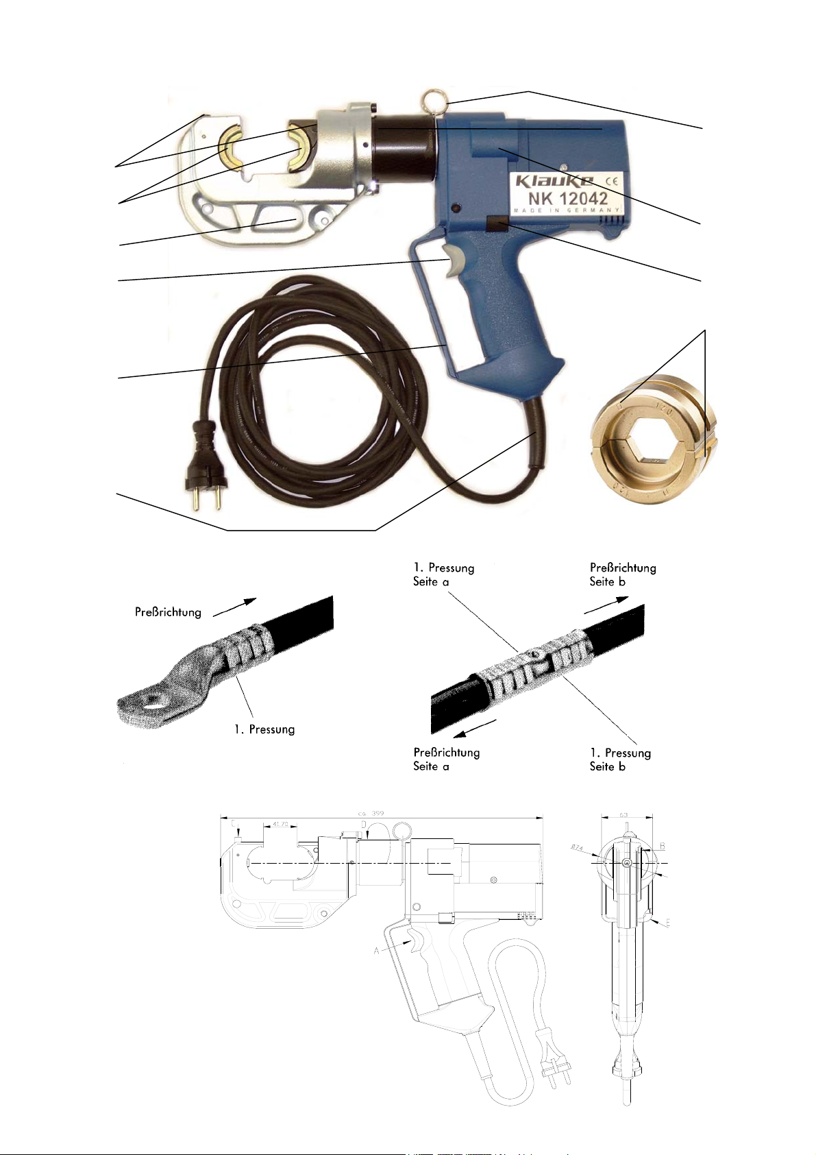
Tabelle 1 (siehe Bild 1 Seite 2)
Pos.-
Bezeichnung Funktion
Nr.
1 Bedienungs-
schalter
2 Rückstelltaste Taste zum Öffnen der Preßeinsätze im
3 Preßkopf C-Kopf zur Aufnahme zur Aufnahme
4 Druckknöpfe Vorrichtung zum Entriegeln der
5 Gehäuse Ergonomisch geformtes Kunststoff-
6 Handschutz Bügel zum Schutz der bedienenden
7 Knickschutz Vermeidung von zu engen Biegeradien
8 Ring Öse zur Sicherung des Gerätes und/oder
9 Preßeinsätze Halbschalen Werkzeugeinsätze mit
4.2 Kurzbeschreibung der wesentlichen Leistungsmerkmale des Gerätes
- Das Gerät besitzt einen automatischen Rücklauf, der den Kolben nach
Erreichen des max. Betriebsüberdruckes automatisch in die
Ausgangslage zurückfährt.
- Das Gerät ist mit einem Nachlaufstop ausgerüstet, der den Vorschub
nach Loslassen des Bedienungsschalters (Pos.-Nr. 1) sofort stoppt.
- Das Gerät ist mit einer Doppelkolbenpumpe ausgestattet, die durch
einen schnellen Vorschub und einen langsamen Arbeitshub
gekennzeichnet ist.
- Der Preßkopf ist stufenlos 360° um die Längsachse drehbar. Dieses
ermöglicht Montagen auch an sehr schlecht zugänglichen Stellen.
5. Hinweise zum bestimmungsgemäßen Gebrauch
Vor Arbeitsbeginn sind alle aktiven, d.h. stromführenden Teile im
Arbeitsumfeld des Monteurs freizuschalten. Ist dieses nicht möglich sind
entsprechende Schutzvorkehrungen
unter Spannung stehenden Teilen zu treffen.
5.1. Bedienung des Gerätes
Nach einer Überprüfung, ob die Netzspannung für das Gerät geeignet
ist, muß der Netzstecker in die Steckdose gesteckt werden. Da das
Werkzeug doppelt isoliert ist, kann es auch an eine nicht geerdete
Steckdose angeschlossen werden.
Dann erfolgt die Auswahl des geeigneten Preßeinsatz (Pos.-Nr. 9).
Anschließend werden die beiden Hälften der Presseinsätze nacheinander
seitlich unter Betätigung der Druckknöpfe (Pos. 4, Bild 2 Stellung C) bis
zum Einrasten eingeschoben.
Der Presskopf sollte möglichst vor Beginn des Pressvorganges in die
gewünschte Position gedreht werden. Im drucklosen Zustand lässt sich
der Presskopf deutlich leichter drehen.
Die Betätigung des Bedienungsschalters (Pos.-No. 1, Bild 2 Stellung A)
leitet den Preßvorgang ein, der durch das Zusammenfahren der
Preßeinsätze gekennzeichnet wird.
Dabei befindet sich das auf den Leiter aufgeschobene
Verbindungsmaterial bei geschlossenem Preßkopf in dem Preßprofil der
stationären Hälfte des Preßeinsatzes
1
Siehe DIN EN 50110-1
2
Siehe Bild 4 – Montagehinweis für Kabelschuhe und Verbinder
Achtung
Preßwerkzeug niemals ohne Preßeinsätze betätigen!
Auslösung des Preßvorgangs
Fehler-, bzw. Notfall
von 12 to Halbschaleneinsätzen
Preßeinsätze
gehäuse
Hand, kein Transportgriff!
des Netzkabels
zu Montagezwecken
unterschiedlichen Preßprofilen
1
für das Arbeiten in der Nähe von
2
.
Page 4

Bedienungsanleitung NK 120/42 Seite 4
_______________________________________________________________________________________________________________________
Ein Preßvorgang ist abgeschlossen, wenn die Preßeinsätze (Pos.Nr. 9) zusammengefahren sind. Der Rücklauf des Kolbens erfolgt
automatisch nach Erreichen des max. Betriebsüberdruckes.
Anschließend kann ein weiterer Preßvorgang vorgenommen
werden oder das Verbindungsmaterial aus dem Preßkopf
herausgenommen werden.
Achtung
Vor Auswechselung der Preßeinsätze
unbedingt Netzstecker ziehen.
Durch Drücken der Rückstelltaste (Pos.-Nr. 2) können im Fehler-,
bzw. Notfall die Preßeinsätze in die Ausgangsposition zurückgefahren werden (Bild 2 Stellung E).
Achtung
Der Preßvorgang kann jederzeit durch Loslassen
des Betätigungsschalters unterbrochen werden.
Achtung
Anschlußleitung nicht für Zwecke verwenden
für die Sie nicht bestimmt ist. Tragen Sie das
Werkzeug niemals an der Anschlußleitung und
benutzen Sie diese Leitung nicht um den Stecker
aus der Steckdose zu ziehen
Achtung
Verwenden Sie im Freien nur dafür zugelassene
Verlängerungsleitungen.
5.2. Erläuterung des Anwendungsbereiches
Das Preßgerät verfügt über eine große Anzahl verschiedener
Preßeinsätze (Pos.-Nr. 9) zum Verpressen von KlaukeVerbindungsmaterial.
Tabelle 2 (siehe Bild 3 auf Seite 2)
Preß-
bereich
Preßeinsätze
mm²
16-400 RKS und VB
DIN ähnlich
16-240 Preß-KS und ~
VB
DIN 46235
Kennzeichnung
außen Preß-
profil
CU, QS QS gelb
CU, QS,
KZ gelb
DIN
46235
Oberfläche
des
Preßeinsatzes
chromatiert
chromatiert
DIN 46267
10-240 Aluminium KS
AL, QS KZ blau verzinkt
und VB
25-185 Al-Preß-VB
Al, QS KZ blau verzinkt
Aldrey
120/20
10-300
sm
DIN 48085 T3
Runddruck-
einsatz
16-150 Quetsch-/Stift-
KS
DIN 46234
Preßverbinder
Al, QS KZ blau verzinkt 25/4St, QS KZ brüniert
RU;
QS, sm;
- gelb
chromatiert
QS, sm
CU, QS,
DIN
QS gelb
chromatiert
46234
DIN 46230
10-95 isolierte
Quetsch-KS
16-150 Rohr-RKS für
feindrähtige
ISQ, QS QS gelb
chromatiert
F, QS QS gelb
chromatiert
Leiter
10-70 C-Abzweig-
klemmen
10-150 RKS und VB
isoliert, Stift-
C, QS - gelb
chromatiert
IS, QS QS gelb
chromatiert
KS isoliert
2x50-
25-240 AEH
25-240 AEH für verd.
Abkürzungen: RKS - Rohr-Kabelschuhe, VB - Verbinder, AEH - Aderendhülsen, QS -
Doppel-Preß-
2x95
RKS
DIN 46228
feind. Leiter
Querschnitt, KZ - Kennzahl
DP, QS QS gelb
chromatiert
AE, QS - gelb
chromatiert
AE, QS - gelb
chromatiert
Achtung
Es dürfen nur die in Tab. 2 genannten
Verbindungsmaterialien verpreßt werden.
Sollten andere Verbindungsmaterialien verpreßt werden müssen, ist eine
Rücksprache mit dem Werk zwingend erforderlich.
Achtung
Es dürfen keine unter Spannung stehenden Teile
verpreßt werden.
Bei der NK 120/42 handelt es sich um ein handgeführtes Gerät, das nicht
eingespannt werden darf. Es darf nicht für den stationären Einsatz
verwendet werden. Unter Einhaltung bestimmter Bedingungen kann das
Gerät auch stationär mit unserem Präsentationsständer EKST betrieben
werden. Die Bedingungen entnehmen Sie bitte der Bedienungsanleitung
des EKST.
Das Gerät ist nicht für den Dauerbetrieb geeignet. Es muß nach ca. 3040 Verpressungen hintereinander eine Pause von ca. 15 min eingelegt
werden um das Gerät abzukühlen.
Achtung
Bei zu intensivem Gebrauch kann es durch Erhitzung zu
Schäden am Gerät kommen.
Achtung
Beim Betrieb von Elektromotoren kann es zur
Funkenbildung kommen, durch die feuer-gefährliche
oder explosive Stoffe in Brand gesetzt werden können.
Achtung
Das elektrohydraulische Preßgerät darf nicht bei starkem
Regen oder unter Wasser eingesetzt werden.
5.3. Verarbeitungshinweise
Bitte beachten Sie unbedingt die im Katalog Kapitel 12 angeführten
Montagehinweise
3
.
Achtung
Es dürfen auch bei gleicher Kennzahl nur die für das
Material vorgesehenen Preßeinsätze verwendet werden.
5.4. Wartungshinweise
Das Preßgerät ist nach jedem Gebrauch zu reinigen und trocken zu
lagern.
Das Gerät ist wartungsfrei, lediglich die Bolzenverbindungen sind leicht
einzuölen.
Bei Beschädigung des Gehäuses ist die Maschine zur Reparatur
einzuschicken.
Kontrollieren Sie regelmäßig die Komponenten des Werkzeuges auf
Beschädigung und auf ihre bestimmungsgemäße Funktion.
Lassen Sie beschädigte Anschlußleitungen und Stecker von einem
Fachmann reparieren, bzw. austauschen.
Im Rahmen des bestimmungsgemäßen Gebrauchs dürfen vom Kunden
nur die Preßeinsätze (Pos.-Nr. 9) gewechselt werden.
Achtung
Geräteversiegelung nicht beschädigen!
Bei Beschädigung der Geräteversiegelung erlischt der Garantieanspruch.
5.5. Aufbewahrung und Transport des Preßgerätes
Um das Preßgerät vor Beschädigungen zu schützen, muß es nach
Gebrauch und nachdem es gesäubert worden ist, in den Transport-koffer
gelegt werden, der dann anschließend sicher zu verschließen ist.
3
Siehe auch Bild 4 auf Seite 2 dieser Bedienunganleitung
Page 5

Bedienungsanleitung NK 120/42 Seite 5
_______________________________________________________________________________________________________________________
6. Verhalten bei Störungen am Preßgerät
a.) Das Preßwerkzeug verliert Öl.
=> Das Gerät einschicken. Das Gerät nicht öffnen und die
Geräteversiegelung nicht entfernen.
b.) Preßwerkzeug erreicht den Enddruck nicht.
=> Preßvorgang unterbrechen. Rückstelltaste (Pos.-Nr. 2)
gedrückt halten und gleichzeitig Bedienungsschalter ca. 10 sec.
Dauerbetätigen. Wird der Fehler dadurch nicht behoben, muß
das Gerät ins Werk eingeschickt werden.
7. Außerbetriebnahme/Entsorgung
Die Entsorgung der einzelnen Komponenten des Aggregates muß
getrennt erfolgen. Dabei muß zuerst das Öl abgelassen werden und
an speziellen Abnahmestellen entsorgt werden.
Bei der Entsorgung der restlichen Teile des Aggregates beachten
Sie bitte die Umweltstandards der Europäischen Gemeinschaft,
respektive der in Ihrem Land geltenden Vorschriften.
Wir empfehlen wegen möglicher Umweltverschmutzung die
Entsorgung durch zugelassene Fachunternehmen vornehmen zu
lassen. Eine kostenfreie Rücknahme des Altgerätes durch den
Hersteller kann nicht zugesagt werden.
8. Technische Daten
Gewicht des kompl. Gerätes: ca. 6,3 kg
Preßkraft: ca. 120 kN
Hub: 42 mm
Nennspannung: 230 V/50Hz
Nennleistung: 200 W
Einschaltdauer: ED 5min/15min
Preßzeit: 12 s bis 16 s (abhängig vom
Schutzklasse: II
Hydrauliköl: ca. 190 ml "Shell Tellus T 15"
Umgebungstemperatur: -20°C bis +40°C
Schalldruckpegel: 75 dB (A) in 1m Abstand
Vibrationen: < 2,5 m/s²
Maße: Siehe Bild 2
Anmerkung
Diese Bedienungsanleitung kann jederzeit kostenlos unter der
Bestell-Nr. HE.10541 nachbestellt werden.
Achtung
Hydrauliköle stellen eine Gefahr für das
Grundwasser dar. Unkontrolliertes Ablassen oder
unsachgemäße Entsorgung steht unter Strafe.
(Umwelthaftungsgesetz)
Verbinderquerschnitt)
(gewichteter Effektivwert der
Beschleunigung)
Instruction Manual
for the mains driven electric-hydraulic crimping unit Type NK 120/42,
Serial-No. ...........................
Index
1 Introduction
2 Labels
3 Warranty
4 Description of the electric-hydraulic crimping unit
4.1 Description of the components
4.2 Brief description of the important features of the unit
5 Remarks in respect of the determined use
5.1 Operation of the units
5.2 Explanation of the application range
5.3 Mounting instructions
5.4 Service and Maintenance instructions
5.5 Storage and transport of the crimping unit.
6 Troubleshooting
7 Putting out of operation/waste disposal
8 Technical data
Symbols
1. Introduction
Use this tool exclusively for its determined use.
Mounting and assembly of connecting material with the help of this tool
must only be performed by specially trained personnel. The minimum
age is 16 years.
This instruction manual has to be carried along during the entire life
span of that tool.
The operator has
- to guaranty the availability of the instruction manual for the user and
- to make sure, that the user has read and understood the instruction
manual.
2. Labels
On the labels fixed on the housing of the tool you’ll find the type
specification name of the manufacturer and the company logo. On the
opposite side of the housing you’ll find a label with a brief presentation
of the scope of manageable cross-sections for copper and aluminium and
the technical data. The serial number is located on the cylinder between
housing and head. On the crimping head you’ll find a warning against
possible injuries during the crimping process.
3. Warranty
If correct operation is guaranteed our warranty is 6 months from the time
of delivery unless otherwise specified by local guidelines and law.
Safety warnings
Please do not disregard these instructions in order to
avoid human injuries and environmental damages.
Operational warnings
Please do not disregard them to avoid damaging the pump
unit.
Before starting to use the tool please read the
instruction manual carefully.
Page 6

Instruction Manual NK 120/42 page 6
________________________________________________________________________________________________________________________
4. Description of the electric-hydraulic crimping unit
4.1. Description of the components
The electric-hydraulic crimping unit type NK 120/42 is a hand
held tool and consists of the following components:
Table 1 (see Picture 1 page 2)
Pos.-No. Description Function
1 Trigger switch to start crimping procedure
2 Retract
button
3 Crimping
head
4 Retaining
button to open the dies in case of
emergency
C-shape crimping head for the
reception of U-type dies
button to unlock/remove the dies
clips
5 Housing ergonomically formed plastic housing
for perfect handling with a detachable
lid
6 Removable
hand guard
7 Bending
protection
guard to protect the operating hand,
not
for transportation
Protection device for mains cord to
prohibit conductor breakage
8 Ring Loop to secure the tool and/or for
assembly purposes
9 Dies interchangeable 12 to crimping dies
4.2. Brief description of the important features of the unit
- The hydraulic unit incorporates an automatic retraction which
returns the piston into its starting position when the maximum
operating pressure is reached.
- The unit is equipped with a special brake which stops the
forward motion of the piston/dies when the trigger (Pos.-No. 1)
is released.
- The unit is equipped with a double piston pump which is
characterised by a rapid approach of the dies (Pos.-No. 9)
towards the connector and a slow crimping motion.
- The crimping head can be smoothly turned by 360° around the
longitudinal axis in order to gain better access to tight corners
and other difficult working areas.
5. Remarks in respect of the determined use
Before starting any work on electrical appliances it must be
safeguarded that there are no live parts in the immediate assembly
area of the user. Is this not possible special precaution measures
for working near live parts must be provided.
5.1. Operation of the unit
First the mains voltage must checked whether it matches with the
required tool voltage and then the mains plug must be plugged into
the socket. Since the unit is dooble insulated you can also use a not
grounded socket to connect the tool the te mains supply.
Now you have to select the right dies (Pos.-No. 9) for the intended
application.
Attention
Don’t operate the tool without dies.
Afterwards the retaining clips (Pos.-# 4) have to be actuated
(Picture 2 Pos. B+C) while the dies will be inserted sideways into
the open crimping head.
The crimping head should be turned into the desired position
before starting the crimping cycle. It is significantly easier to turn
the crimping head in a pressure free state.
The crimping procedure is initiated by actuating the trigger (Pos.No. 1 & Picture 2 Pos. A). The crimping process is defined by the
closing motion of the dies. During that process the connecting
material is positioned in the stationary half of the die whereas the
moving part of the die is approaching the compression point
1
See EN 50110-1
3
See picture 4 page 2
1
3
.
The crimping process is terminated when the crimping force is reached.
After having completed the crimp the dies return into the starting
position automatically.
Attention
After having terminated the crimping process and
prior to changing the dies pull plug out of socket.
In case of error or emergency the dies can be returned into the starting
position by actuating the retract button (Pos.-No. 2 & Picture 2 Pos. E).
Attention
The crimping cycle can be interrupted at any moment by
releasing the trigger.
Attention
Do not use the power cord for unintended purposes.
Don’t carry the tool by the power cord and don´t use the
cord to pull the plug out of the power receptacle.
Attention
When working outdoors, use only approved extension
cables.
5.2. Explanation of the application range
The NK 120/42 has a large number of various dies (Pos.-No. 9) available
to crimp Klauke connecting material.
Table 2 (see Picture 3, page 2)
Crimping
range
mm²
16-400 TCL and C.
Crimping dies
Standard
Marking
outside profile
CU,
„QS“ chrome
„QS“
Version
16-240 TCL and C.
DIN 46235
DIN 46267
10-240 Aluminium CL
and C.
25-185 Aluminium C.
Aldrey
Full tension C.
120/20
DIN 48085 T3
CU, QS
DIN
46235
AL,
„QS“
Al,
„QS“
Al,
„QS“
ST,
10-240
sm
Pre-rounding
dies
35-300 se
16-150 Terminals
DIN 46234
DIN 46230
10-95 insulated
„QS“
RU;
QS, sm;
QS, sm
CU, QS
DIN
46234
ISQ, QS „QS“ chrome
code # chrome
code # blue zinc
code # blue zinc
code # blue zinc 25/4-
code # black
- chrome
„QS“ chrome
terminals
16-150 tub. CL for
F, QS „QS“ chrome
fine-str.
conductors
4-70 C-clamps C, QS - chrome
10-150 pre-insulated
IS, QS „QS“ chrome
tub. CL and
connectors
2x50-
2x95
10-95 Oval
double compression CL
compression
DP, QS „QS“ chrome
CU or
code # chrome
AL, QS
joints
25-240 WF DIN
AE, QS - chrome
46228
25-240 WF for comp
AE, QS - chrome
fine stranded
conductors
Abbreviations: TCL-Tubular cable lugs, C-Connectors, WF-Wire
Ferrules, QS-Cross-section
Attention
Do only crimp those connecting materials mentioned in
Tab. 2
Surface of
the dies
plated
(yellow)
plated
plated
plated
plated,
plated
plated
plated
plated
plated
plated
plated
Page 7

Instruction Manual NK 120/42 page 7
________________________________________________________________________________________________________________________
If different conducting materials have to be crimped, please
contact the manufacturer.
The NK 120/42 is a hand held tool and it is not supposed to be
restrained in a vise. It is not allowed to use the tool in a stationary
application. Complying certain conditions the unit can be operated
stationary with our presentation support EKST. The conditions can
be taken from the instruction manual of the EKST.
The tool is not designed for continued crimping operations. After a
sequence of approximately 30-40 completed crimps you have to
make a break of 15 min. to give the tool time to cool down.
5.3. Mounting instructions
Please read the assembly instructions in Chapter 12 of our general
catalogue.
Please use the following assembly instructions for cable lugs and
connectors:
1. Strip the conductor according to insertion depth (+10% due to
the change of length of the crimped sleeve)
2. The Conductor ends must be cleaned with a cloth or brush
before the assembly.
3. Insert the conductor fully into the cable lug or connector
4. Pay attention to the crimping directions and use the appropriate
dies. The crimping directions
indicated in the illustration below.
5. After crimping, wipe away excess compound forced out of Alcable lugs and connectors.
5.4 Service and maintenance instruction
In case of broken moldings please return the tool to an authorised
service center.
Check the tool components regularly for damages and proper
operation and performance of their intended functions.
Have damaged cords and plugs repaired by a qualified serviceman.
Within the determined use of the tool only the dies (Pos.-No. 9) are
permitted to be changed by the customers.
If the seals are damaged the warranty is invalidated.
5.5 Storage and transport of the crimping tool
In order to protect the tool against damages it has to be cleaned
carefully after each use and be put into the transportation case
which has to be closed safely.
Attention
Do not crimp on live cables or conductors
Attention
Too intensive use can cause heat damages for the
tool
Attention
During the operation of electric engines sparks can
occur which might ignite highly inflammable or
explosive liquids and materials
Attention
Electric-hydraulic crimping tools should not be
operated in pouring rain or under water.
Attention
Even if the code number is identical only those dies
should be used whichare suitable for the material.
3
for cable lugs and connectors is
Attention
Do not damage the seals of the tool.
6. Troubleshooting
a.) The tool loses oil.
=> Return the tool to the manufacturer. Do not open the tool and
damage the seals of the tool.
b.) The crimping tool does not reach the final operating pressure.
=> Stop the crimping process. Press the retract button (Pos.-No. 2) and
the operating switch continuously and simultaneously for about 10
sec. Is the malfunction not be eliminated by this attempt the tool has to
be returned to the manufacturer.
7. Putting out of operation/waste disposal
The disposal of the various components of the tool has to be treated
separately. First you have to dispose of the oil at special delivery points.
For the disposal of the remaining parts please reference the EC
environmental guideline.
Because of possible environmental damages we recommend to dispose
of the tool by professional companies. A return of the old tool free of
charge to the manufacturer cannot be granted.
8. Technical Data
Weight of the complete tool: approx. 6,3 kg
Crimping force: approx. 120 kN
Stroke: 42 mm
Nominal voltage: 230V/50Hz
Nominal power: 200 W
Duty cycle: ED 5min/15min
Crimping time: approx. 12 s to 16 s
(depending on the connector size)
Hydraulic oil: approx. 190 ml "Shell Tellus T 15"
Environmental temperature: -20°C to +40°C
Protection class: II
Sound level: 75 dB (A) in 1m distance
Vibrations: < 2,5 m/s²
Dimensions: See Picture 2
Note
Additional instruction manuals are available free of charge. The part # is
HE.10541.
Attention
Hydraulic oils represent a danger for the ground-water.
Uncontrolled draining of or improper disposal is under
penalty. (environmental liability law)
4
See Picture 4 on Page 2
Page 8

Service NK 120/42 Seite/page 8
______________________________________________________________________________________________________________________
DEUTSCHLAND Klauke Remscheid
FRANKREICH: KLAUKE FRANCE
GROSSBRITTANIEN Norwich Instrument Services
ISRAEL: Shay A.U., Ltd.
Mr. Shay
Ind. Zone Kiriat Arieh
Embar Street 23/25
P.O. BOX 10049
49222 Petach Tikva (Israel)
Tel.: ++972-3-9233601
Fax: ++972-3-9234601
E-MAIL: a_u-shay@nezvision.net.il
ITALIEN: F.B. Spa
Mr. Victor Drozdowski
Via Buonarroti, 11
61030 Borgaccio di Soltara (PU)
Fax: ++39-0721-879602
E-MAIL: produzione@fb-
NIEDERLANDE: H.K. Electric B.V.
Mr. Kleijn
De Steegen 7
5321 JZ Hedel (Niederlande)
Tel.: ++31-73-5997599
Fax: ++31-73-5997590
E-Mail: hke@csi.com
ÖSTERREICH: KLAUKE Handelsgesellschaft mbH
Mr. Acham
Kaiser-Franz-Josef-Str. 9
1230 Wien (Österreich)
Tel.: ++43-1-8893436
Fax: ++43-1-8893433
E-MAIL: office@klauke.at
POLEN/ UKRAINE: RB Brexim S.A.
05-825 Grodzisk Mazowiecki
PORTUGAL: Palissy Galvani Electricidade Lda.
Mrs. Anna Pereira
Rua Serpa Pinto, 15-A/P
1200 Lisboa (Portugal)
Tel.: ++351-21-3223400
Fax: ++351-21-3223410
Herr Radtke
Auf dem Knapp 46
42855 Remscheid
Tel.: ++49 (0)2191/907-168
Fax: ++49 (0)2191/907-242
e-mail: service@klauke.textron.com
M. Weiten
16, Rue Saint-Louis
Z.I. Actisud
57150 Creutzwald (France)
Tel.: ++33-3-87298470
Fax: ++33-3-87298479
E-MAIL: klauke.france@free.fr
Mr. Norman Cockburn
32 Hellesdon Park Road
Drayton High Road
Norwich NR6 5DR (UK)
Tel.: 0044-1603-416900
Fax: 0044-1603-416902
E-Mail: norman@nisltd.co.uk
(Italy)
Tel.: ++39-0721-892168
avvolgitori.it
Marynin 7a
(Polen)
Tel.: ++48-22-7920273 oder 75
Fax: ++48-22-7923055
E-MAIL: RB.office@brexim.pl
SLOWENIEN: Isaria d. o.o.
SPANIEN/ ANDORRA: Gave Electro S.A.
TSCHECHISCHE REPUBLIK/
SLOVAKEI: Jiri Nitsch
VOLKSREPUBLIK CHINA: Excellence Eng. & Trade Co,
(lokaler Partner) Mr. Paul Wu
(lokaler Partner) Beijing Tian Ze Electric Power
(Service Ansprechpartner) Shanghai PuHuiFeng Machinery
KOREA: Taehyung Hydraulic Tool
SCHWEDEN Miltronic AB
NORWEGEN Miltronic AS
Mrs. Zorz
Proizvdnja in trgovina
Cece 2a
1420 Trovlje (Slowenien)
Tel.: ++386-356-31800
Fax: ++386-356-3180
Mr. Fernando Carvalho
Paratge Coll-Blanc, S/N
Aptdo. 12
08430 La Roca del Valles,
Barcelona (Spanien)
Tel.: ++34-93-8422212
Fax: ++34-93-8422227
E-MAIL: gave@gave.com
M. Pujmanove 1220/31
14000 Praha 4 – Prankrac
(Tschechische Republik)
Tel.: ++42-2-61213220
Fax: ++42-2-61213218
Rm 1207B, T.P Plaza
9/109, LiuHua Road
5100010 Guagzhou (P.R. China)
Tel.: ++86-20-86671150
Fax: ++86-20-86671141
E-MAIL: excellence@21cn.com
Equipment Co.Ltd.
Mr. Yu Yong
Room 223-225 Juan Plaza
No. 18 Bai Zi Wan Road
Chaoyang District
100022 Beijing (P.R. China)
Tel.: ++86-10-67706841
Fax: ++86-10-67718723
E-MAIL: yuyong@tze.com.cn
Equipment Maintenance Co.Ltd.
Mr. Zhang Yulian
No.7, 234 Changning Road
200042 Shanghai (China ZIP)
Tel.: ++86-21-62254404
Fax: ++86-21-62254404
Mr. Kim
140-5, Gamjeun-Dong, Sasang-Gu
Busan 17-060 (Korea)
Tel.: ++82-51-3171507
Fax: ++82-51-3171507
E-Mail: thhyd@hanmail.net
Mr. Thomas Fred
Kungshagsvägen 7
S-611 29 Nyköping (Schweden)
Tel.: 0046-155-77700
Fax: 0046-155-77702
E-Mail: thomas.fred@miltronic.se
Mr. Hans Petter Selbo
Dolasletta 5, 4308 Transby
N-3421 Lierskogen (Norwegen)
Tel.: 0047-32226610
Fax: 0047-32226656
E-Mail: hans.petter.selbo@miltronic.no
Page 9

Service NK 120/42 Seite/page 9
______________________________________________________________________________________________________________________
UNGARN Trend Elektro
TÜRKEI Ünal Kardes
Schweden
Bulgarien
RUSSLAND Unit Mark Pro
RUMÄNIEN: Gerkon S.R.L.
KROATIEN: Konekt d.o.o.
SCHWEIZ: Ferratec AG
Geplante (planned) Service-Center in 2004:
LIBANON Georges Khoury & Co
IRLAND: Mangan Wholesale Ltd.
FINNLAND OYElteosähkö AB
Mr. Istvan Imrik
H-1117 Budapest
Dombovari ut 5-7 (Ungarn)
Tel.: 0036-1-464-3118
Fax: 0036-1-464-3119
E-Mail: trendelektro@freemail.hu
Mr. Servet Diricanli
Eski Londra Asfalti No. 6
34630 Desyol-SefaköyIstanbul (Türkei)
Tel.: 0090-212-6249204
Fax: 0090-212-5924810
E-Mail: sdiricanli@unalkardes.com.tr
Mr. Alexander Naichouller
119147 Moscow
Marksistskaya 34, bldg 10
(Russland)
Tel.: 007-095-7480907
Fax: 007-095-7480909
E-Mail: mark@unit.ru
Mr. Heim
Miercurea Ciuc
Str. Eminescu 1
4100 Miercurea Ciuc
(Rumänien)
Tel.: 0040-266-372108
Fax: 0040-266-112238
e-Mail: gerkonelectro@kabelkon.ro
Mr. Dubravko Salkovic
Cerinina
HR-10000 Zagreb (Kroatien)
Tel.: 00385-12361890
Fax: 00385-12361882
E-Mail: konekt@zg.tel.hr
Mr. Bürgisser
Großmattstr. 19
CH-8964 Rudolfstetten
Tel.: 0041-56-6492121
Fax: 0041-56-6492141
E-Mail: info@ferratec.ch
Mr. Alec Kouladjian
p.o. box 11-8251 Bauchrieh
Beirut-Lebanon (Libanon)
Tel.: 00961-1-873872
Fax: 00961-1-894642
E-Mail: aleck@gkhoury.com
Chapelizod
39/40, Main Street
Dublin 20 (Irland)
Tel.: 00353-1-6267611
Fax: 00353-1-6267613
E-Mail: jpmangan@tinet.ie
Mr. Reijo Karlsosson
Kärsämäentie 23,
20360 Turku (Finnland)
Tel.: 00358-2-4100200
Fax: 00358-2-4100229
E-Mail: info@elteo.fi
SÜDARFIKA Eberhardt Martin CC
DÄNEMARK Wexoe A/S
Mr. Roger Martin
55 Evelyn Street
Newland Johannesburg
Post point Delarey 2114
Tel.: 0027-11-6732043
Fax: 0027-11-6732036
E-Mail: ebm@mweb.co.za
Skaettekaeret 11
DK-3840 Holte (Dänemark)
Tel.: 0045-45465800
Fax: 0045-45465801
E-Mail: wexoe@wexoe-as.dk
Page 10

Auf dem Knapp 46
D-42855 Remscheid
____________________________________________________________________________________________________________________
Handgeführtes Elektrowerkzeug Typ NK 120/42
(D) CE`02 - Konformitätserklärung. Wir erklären in alleiniger Verantwortlichkeit, daß dieses Produkt mit den folgenden Normen oder
normativen Dokumenten übereinstimmt:
DIN EN 292 Teil 1 und 2, EN 294, EN 349, EN 60204-1, EN 28662-1, EN 50081-1, EN 55014-2, EN 60529, EN 50144-1
gemäß den Bestimmungen der Richtlinien 89/392/EWG, 89/336/EWG, 73/23/EWG.
(GB) CE`02 - Declaration of conformity. We declare under our sole responsibility that this product is in conformity with the following standards
or normative documents:
DIN EN 292 Teil 1 und 2, EN 294, EN 349, EN 60204-1, EN 28662-1, EN 50081-1, EN 55014-2, EN 60529, EN 50144-1
in accordance with the regulations of directives 89/392/EEC, 89/336/EEC, 73/23/EEC.
(F) CE`02 - Déclaration de conformité. Nous déclarons sous notre seule reponsabilité que ce produit est en conformité avec les normes ou
documents normatifs suivants:
DIN EN 292 Teil 1 und 2, EN 294, EN 349, EN 60204-1, EN 28662-1, EN 50081-1, EN 55014-2, EN 60529, EN 50144-1
conformément aux réglementations des directives 89/392/CEE, 89/336/CEE, 73/23/CEE.
(NL) CE`02 - Konformiteitsverklaring. Wij verklaren en wij stellen ons er alleen voor verantwoordelijk dat dit produkt voldoet aan de volgende
normen of normatieve documenten:
DIN EN 292 Teil 1 und 2, EN 294, EN 349, EN 60204-1, EN 28662-1, EN 50081-1, EN 55014-2, EN 60529, EN 50144-1
overeenkomstig de bepalingen van de richtlijnen 89/392/EEG, 89/336/EEG, 73/23/EEG.
(I) CE`02 - Dichiarazione di conformità. Dichiariamo sotto la nostra esclusiva responsabilità
che questo prodotto è conforme alle seguenti norme e documenti normativi:
DIN EN 292 Teil 1 und 2, EN 294, EN 349, EN 60204-1, EN 28662-1, EN 50081-1, EN 55014-2, EN 60529, EN 50144-1
conformemente alle disposizioni delle direttive 89/392/CEE, 89/336/CEE, 73/23/CEE.
(E) CE`02 - Declaración de conformidad. Declaramos bajo nuestra sola responsabilidad que este producto està en conformidad con las normas o
documentos normativos siguientes:
DIN EN 292 Teil 1 und 2, EN 294, EN 349, EN 60204-1, EN 28662-1, EN 50081-1, EN 55014-2, EN 60529, EN 50144-1
de acuerdo con las regulaciones de las directivas 89/392/CEE, 89/336/CEE, 73/23/CEE.
(P) CE`02 - Declaração de conformidade. Declaramos sob nossa exclusiva responsabilidade que este producto cumpre as seguintes normas ou
documentos normativos:
DIN EN 292 Teil 1 und 2, EN 294, EN 349, EN 60204-1, EN 28662-1, EN 50081-1, EN 55014-2, EN 60529, EN 50144-1
conforme as disposiçoes das directivas 89/392/CEE, 89/336/CEE, 73/23/CEE.
(S) CE`02 - Konformitetsdeklaration. Vi förklarar pá eget ansvar att denna produkt õverenstämmer med följande normer eller normativa
dokument:
DIN EN 292 Teil 1 und 2, EN 294, EN 349, EN 60204-1, EN 28662-1, EN 50081-1, EN 55014-2, EN 60529, EN 50144-1
enligt bestãmmelserna i direktiverna 89/392/EG, 89/336/EG, 73/23/EG.
(FIN) CE`02 - Todistus slandardinmukaisuudesta. Asiasta vastaavana todistamme täten, että tämä tuote on seuraavien standardien ja
standardoimisasiakirjojen vaatimusten mukainen:
DIN EN 292 Teil 1 und 2, EN 294, EN 349, EN 60204-1, EN 28662-1, EN 50081-1, EN 55014-2, EN 60529, EN 50144-1
ja vastaa säädoksiä 89/392/EU, 89/336/EU, 73/23/EU.
(N) CE`02 - Konformitetserklæring. Vi erklærer på eget ansvarlighet at dette produkt er i overensstemmelse med følgende standarder eller
standard-dokumenter:
DIN EN 292 Teil 1 und 2, EN 294, EN 349, EN 60204-1, EN 28662-1, EN 50081-1, EN 55014-2, EN 60529, EN 50144-1
i henhold til bestemmelsene i direktive ne 89/392/EØF, 89/336/EØF, 73/23/EØF.
(DK) CE`02 - Konformitetserklæring. Vi erklærer under almindeligt ansvardt at dette produkt er i overensstemmelse med folgende normer eller
normative dokumenter:
DIN EN 292 Teil 1 und 2, EN 294, EN 349, EN 60204-1, EN 28662-1, EN 50081-1, EN 55014-2, EN 60529, EN 50144-1
i henhold til bestemmelseme i direktiverne 89/392/EØF, 89/336/EØF, 73/23/EØF.
(PL) CE`02 - Zgodnosc z dyrektywami CE. Swiadomi odpowiedzialnosci oswiadczamy, ze niniejszy produkt jest zgodny z nastepujacymi
normami lub dokumentacja normatywna:
DIN EN 292 Teil 1 und 2, EN 294, EN 349, EN 60204-1, EN 28662-1, EN 50081-1, EN 55014-2, EN 60529, EN 50144-1
zgodnie z postanowieniami wytycznych 89/392/EWG, 89/336/EWG, 73/23/EWG.
(GR) CE`02 - ∆ΗΛΩΣΗ ΣΥΜΜΟΡΦΩΣΗΣ Με αναληψη συνολικης δηλωνοµε. οτι το πορον προιον συµϕωνει µε τα παρακατω
ποοτυπα και µε τα ηροτυηα ηου αναϕερονται στα σχεπκο εγγραϕα
DIN EN 292 Teil 1 und 2, EN 294, EN 349, EN 60204-1, EN 28662-1, EN 50081-1, EN 55014-2, EN 60529, EN 50144-1
συµϕωνα µε τοχς κονονισµους 89/392/EEC, 89/336/EEC, 73/23/EEC.
Remscheid, den 17.09.2004
____________________________________________
Dipl.-Ing. Joh.-Christoph Schütz, CE-Beauftragter
 Loading...