

Page 1

Bedienungsanleitung
Instruction Manual
Bedieningshandleiding
Version 1.b 6/02
JCS HE.9620_B
Bedienungsanleitung
Instruction Manual
Bedieningshandleiding
Version 1.b 6/02
JCS HE.9620_B
Page 2
Bedienungsanleitung HK120/25 Seite 2
_____________________________________________________________________________
Bild/Picture 1
1 2 6 3
4 5
Bild/Picture 2
1
Bedienungsanleitung HK120/25 Seite 2
_____________________________________________________________________________
Bild/Picture 1
1 2 6 3
4 5
Bild/Picture 2
1
Page 3

Bedienungsanleitung HK120/25 Seite 3
_____________________________________________________________________________
Bedienungsanleitung
für das handhydraulische Preßgerät Typ HK120/25, Seriennummer ..................................
Inhaltsangabe
1. Einleitung
2. Aufschriften
3. Gewährleistung
4. Beschreibung des handhydraulischen Preßgerätes
5. Hinweise zum bestimmungsgemäßen Gebrauch
5.1. Bedienung des Gerätes
5.2. Erläuterung des Anwendungsbereiches
5.3. Verarbeitungshinweise
5.4. Wartungshinweise
5.5. Aufbewahrung und Transport des Preßgerätes
5.6. Hinweis, welche (Ersatz-) Teile vom Kunden selber ausgewechselt werden dürfen.
6. Verhalten bei Störungen am Preßgerät
7. Außerbetriebnahme/Entsorgung
8. Technische Daten
Page 4
Bedienungsanleitung HK120/25 Seite 4
_____________________________________________________________________________
Symbole Sicherheitstechnische Hinweise
Bitte unbedingt beachten, um Personen-
und Umweltschäden zu vermeiden.
Anwendungstechnische Hinweise
Bitte unbedingt beachten, um Schäden am
Gerät zu vermeiden.
1. Einleitung
Vor Inbetriebnahme Ihres Preßgerätes lesen Sie sich die
Bedienungsanleitung sorgfältig durch.
Benutzen Sie dieses Gerät ausschließlich für den bestimmungsgemäßen Gebrauch.
Einbau und Montage von Verbindungsmaterial mit Hilfe dieses Werkzeuges darf nur durch
eine elektrotechnisch unterwiesene Person erfolgen. Das Mindestalter beträgt 16 Jahre.
Diese Bedienungsanleitung ist während der gesamten Lebensdauer des Gerätes
mitzuführen.
Der Betreiber muß
- dem Bediener die Betriebsanleitung zugänglich machen und
- sich vergewissern, daß der Bediener sie gelesen und verstanden hat.
Page 5

Bedienungsanleitung HK120/25 Seite 5
_____________________________________________________________________________
2. Aufschriften
Auf dem Pumpkörper finden Sie einen Aufkleber mit der Typbezeichnung, der
Herstellerangabe und technischen Daten. Die Seriennummer befindet sich auf dem
Hydraulikzylinder.
3. Gewährleistung
Die Gewährleistung bei sachgemäßer Bedienung des Gerätes beträgt 12 Monate ab
Lieferdatum.
Page 6

Bedienungsanleitung HK120/25 Seite 6
_____________________________________________________________________________
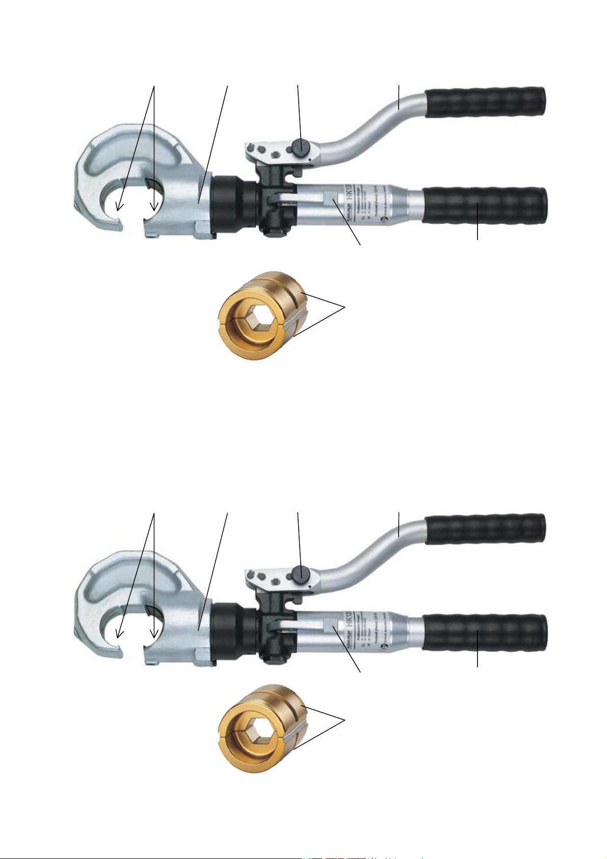
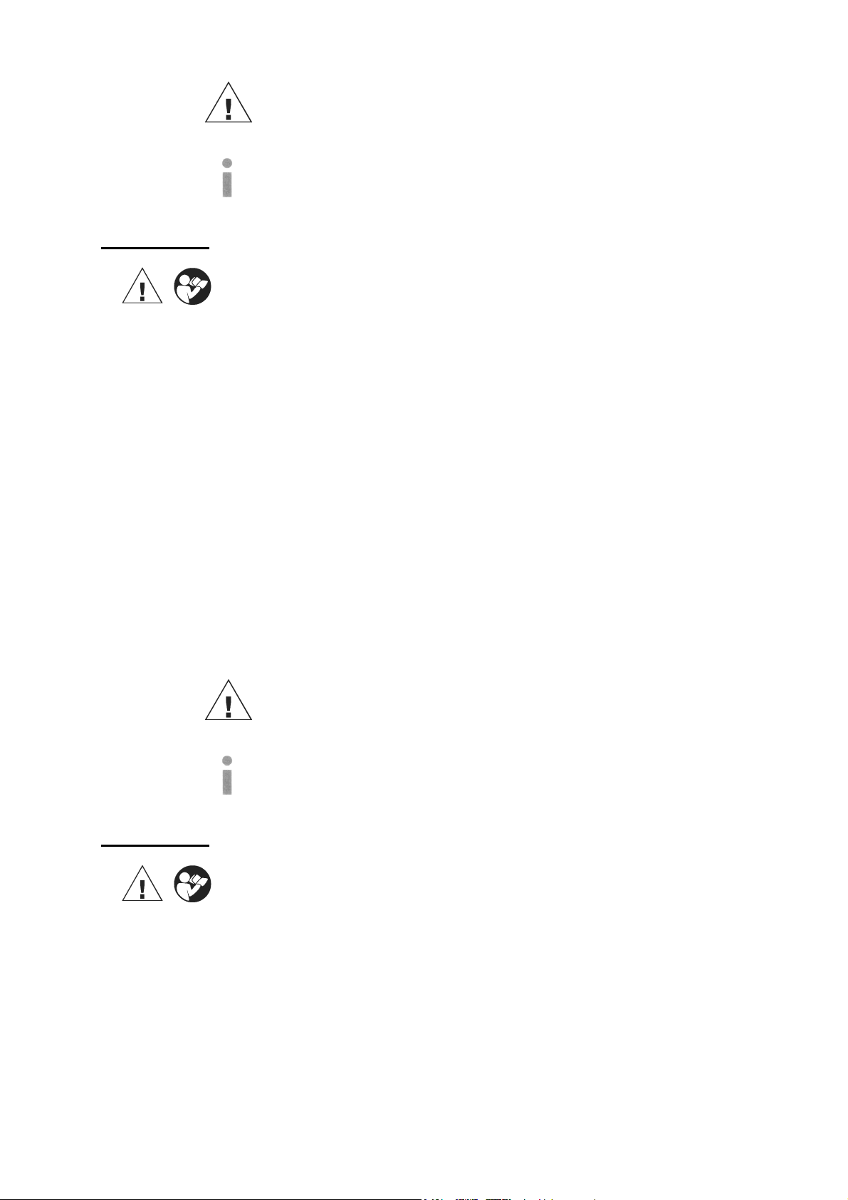
4. Beschreibung des handhydraulischen Preßgerätes
Das hydraulische Preßgerät mit unserer Typbezeichnung HK120/25 ist ein handbetätigtes
Gerät und besteht aus folgenden Komponenten:
Tabelle 1 (siehe Seite 2)
Pos.-Nr. Bezeichnung Funktion Referenz
1 Preßeinsätze Halbschalen Werkzeugeinsätze mit
unterschiedlichen Preßprofilen
2 Preßkopf 120 kN C-Preßkopf für breite Preßeinsätze S 7, 8
3 Pumphebel Hebel zur Durchführung des Preßvorganges S 7, 12
4 Rückstellhebel Hebel zum Öffnen der Preßeinsätze im
Fehler-/Notfall
5 Griff zum Führen des Werkzeuges S 7
6 Transportsicherung Arretierung des Pumphebels S 7
Bedienungsanleitung HK120/25 Seite 6
_____________________________________________________________________________
S 7, 9+10,
12
S 8, 12
4. Beschreibung des handhydraulischen Preßgerätes
Das hydraulische Preßgerät mit unserer Typbezeichnung HK120/25 ist ein handbetätigtes
Gerät und besteht aus folgenden Komponenten:
Tabelle 1 (siehe Seite 2)
Pos.-Nr. Bezeichnung Funktion Referenz
1 Preßeinsätze Halbschalen Werkzeugeinsätze mit
unterschiedlichen Preßprofilen
2 Preßkopf 120 kN C-Preßkopf für breite Preßeinsätze S 7, 8
3 Pumphebel Hebel zur Durchführung des Preßvorganges S 7, 12
4 Rückstellhebel Hebel zum Öffnen der Preßeinsätze im
Fehler-/Notfall
5 Griff zum Führen des Werkzeuges S 7
6 Transportsicherung Arretierung des Pumphebels S 7
S 7, 9+10,
12
S 8, 12
Page 7

Bedienungsanleitung HK120/25 Seite 7
_____________________________________________________________________________
5. Hinweise zum bestimmungsgemäßen Gebrauch
5.1. Bedienung des Gerätes
Als erstes wird für die gewünschte Anwendung das geeignete Preßeinsatzpaar (Pos.-Nr. 1)
bereitgelegt.
Achtung
Preßwerkzeug niemals ohne Preßeinsätze verwenden!
Anschließend werden die Preßeinsätze nacheinander seitlich in den Preßkopf (Pos.-Nr. 2)
eingeschoben bis sie mittig einrasten. Anschließend wird das Verbindungsmaterial in den
Preßkopf eingelegt. Um den Preßvorgang einleiten zu können muß die Transportsicherung
(Pos.-Nr. 6) durch Drücken des Pumphebels (Pos.-Nr. 3) in Richtung des Griffs (Pos.-Nr. 5)
und Drehen des Knopfes um 180° freigeschaltet werden.
Ein Preßvorgang wird durch die Betätigung des Pumpenhebels (Pos.-Nr. 3) in Form von
Pumpbewegungen eingeleitet.
Der Preßvorgang wird gekennzeichnet durch das Zusammenfahren der Preßeinsätze. Dabei
befindet sich das auf das Kabel aufgeschobene Verbindungsmaterial bei geschlossenem
Preßkopf in dem Preßprofil der stationärem Hälfte des Preßeinsatzes. Der auf der Kolbenstange sitzende bewegliche Teil des Preßeinsatzes bewegt sich auf die Preßstelle zu.
Bedienungsanleitung HK120/25 Seite 7
_____________________________________________________________________________
5. Hinweise zum bestimmungsgemäßen Gebrauch
Als erstes wird für die gewünschte Anwendung das geeignete Preßeinsatzpaar (Pos.-Nr. 1)
bereitgelegt.
Achtung
Preßwerkzeug niemals ohne Preßeinsätze verwenden!
Anschließend werden die Preßeinsätze nacheinander seitlich in den Preßkopf (Pos.-Nr. 2)
eingeschoben bis sie mittig einrasten. Anschließend wird das Verbindungsmaterial in den
Preßkopf eingelegt. Um den Preßvorgang einleiten zu können muß die Transportsicherung
(Pos.-Nr. 6) durch Drücken des Pumphebels (Pos.-Nr. 3) in Richtung des Griffs (Pos.-Nr. 5)
und Drehen des Knopfes um 180° freigeschaltet werden.
Ein Preßvorgang wird durch die Betätigung des Pumpenhebels (Pos.-Nr. 3) in Form von
Pumpbewegungen eingeleitet.
Der Preßvorgang wird gekennzeichnet durch das Zusammenfahren der Preßeinsätze. Dabei
befindet sich das auf das Kabel aufgeschobene Verbindungsmaterial bei geschlossenem
Preßkopf in dem Preßprofil der stationärem Hälfte des Preßeinsatzes. Der auf der Kolbenstange sitzende bewegliche Teil des Preßeinsatzes bewegt sich auf die Preßstelle zu.
Page 8

Bedienungsanleitung HK120/25 Seite 8
_____________________________________________________________________________
Das Werkzeug ist mit einem Doppelkolben ausgestattet, der einen schnellen Vorschub und
einen lansamen Arbeitshub aufweist. Im Niederdruckbereich wird beim Öffnen des Pumpenhebels (Pos.-Nr. 3) der schnelle Vorschub realisiert, beim Schließen ein langsamer. Im
Hochdruckbereich wird nur beim Schließen ein Kolbenvorschub bewirkt.
Ein Preßvorgang ist abgeschlossen, wenn die Werkzeugeinsätze vollständig zusammengefahren sind und die maximale Preßkraft erreicht wurde. Dieses wird durch ein spürbares
Nachlassen der Handkraft angezeigt.
Nach vollendeter Pressung erfolgt ein automatischer Rücklauf des Kolbens. Im Fehlerfalle
können durch Drücken des Rückstellhebels (Pos.-Nr. 4) die Preßeinsätze (Pos.-Nr. 1)
jederzeit manuell in die Ausgangsposition zurückgefahren werden. Anschließend kann
entweder ein weiterer Preßvorgang vorgenommen werden oder das Verbindungsmaterial aus
dem Preßkopf (Pos.-Nr. 2) herausgenommen werden.
Bedienungsanleitung HK120/25 Seite 8
_____________________________________________________________________________
Das Werkzeug ist mit einem Doppelkolben ausgestattet, der einen schnellen Vorschub und
einen lansamen Arbeitshub aufweist. Im Niederdruckbereich wird beim Öffnen des
Pumpenhebels (Pos.-Nr. 3) der schnelle Vorschub realisiert, beim Schließen ein langsamer.
Im Hochdruckbereich wird nur beim Schließen ein Kolbenvorschub bewirkt.
Ein Preßvorgang ist abgeschlossen, wenn die Werkzeugeinsätze vollständig zusammengefahren sind und die maximale Preßkraft erreicht wurde. Dieses wird durch ein spürbares
Nachlassen der Handkraft angezeigt.
Nach vollendeter Pressung erfolgt ein automatischer Rücklauf des Kolbens. Im Fehlerfalle
können durch Drücken des Rückstellhebels (Pos.-Nr. 4) die Preßeinsätze (Pos.-Nr. 1)
jederzeit manuell in die Ausgangsposition zurückgefahren werden. Anschließend kann
entweder ein weiterer Preßvorgang vorgenommen werden oder das Verbindungsmaterial aus
dem Preßkopf (Pos.-Nr. 2) herausgenommen werden.
Page 9

Bedienungsanleitung HK120/25 Seite 9
_____________________________________________________________________________
5.2. Erläuterung des Anwendungsbereiches
Unser hydraulisches Preßwerkzeug verfügt über eine große Anzahl verschiedener
Preßeinsätze (Pos.-Nr. 1) zum Verpressen von Cu- und Al-Verbindungsmaterial.
Tabelle 2 (siehe Bild 2)
Preßbereich Kennzeichnung
mm²
16-400 RKS und VB
16-240 Preß-KS und –VB
10-240 Aluminium KS und VB AL, QS Kennzahl blau verzinkt
25-185 Al-Preßverbinder Aldrey Al, QS Kennzahl blau verzinkt
10-300 sm Runddruckeinsatz RU; QS, sm;
16-150 Quetsch-/Stift-KS
10-95 isolierte Quetsch-KS ISQ, QS QS gelb chromatiert
16-150 Rohr-RKS für
10-70 C-Abzweigklemmen C, QS - gelb chromatiert
Preßeinsätze
Normalausführung
DIN 46235/DIN 46267
DIN 48085 T3
DIN 46234/DIN 46230
feindrähtige Leiter
außen Preßprofil
CU, QS QS gelb chromatiert
CU, QS,
DIN 46235
Al, QS Kennzahl blau verzinkt 25/4-120/20 Preßverbinder
St, QS Kennzahl brüniert
QS, sm
CU, QS,
DIN 46234
F, QS QS gelb chromatiert
Kennzahl gelb chromatiert
- gelb chromatiert
QS gelb chromatiert
Oberfläche des
Preßeinsatzes
Page 10

Bedienungsanleitung HK120/25 Seite 10
_____________________________________________________________________________
Tabelle 2 (Fortsetzung)
Preßbereich Kennzeichnung
mm²
10-150 RKS und VB isoliert,
2x50-2x95 Doppel-Preß-RKS DP, QS QS gelb chromatiert
25-240 AEH DIN 46228 AE, QS - gelb chromatiert
25-240 AEH für verdichtete
Abkürzungen: RKS-Rohr-Kabelschuhe, VB-Verbinder, AEH-Aderendhülsen, QS-Querschnitt
Preßeinsätze
außen Preßprofil
IS, QS QS gelb chromatiert
Stift-KS isoliert
AE, QS - gelb chromatiert
Leiter
Oberfläche des
Preßeinsatzes
Achtung
Es dürfen nur die in Tabelle 2 angeführten Verbindungsmaterialien verpreßt
werden.
Sollten andere Verbindungsmaterialien verpreßt werden müssen, ist eine Rücksprache mit
dem Werk zwingend erforderlich.
Achtung
Desweiteren dürfen keine unter Spannung stehenden Teile verpreßt werden.
Vor Arbeitsbeginn ist zwingend ein spannungsfreier Zustand der zu verpressenden
Verbindung sicherzustellen.
Bedienungsanleitung HK120/25 Seite 10
_____________________________________________________________________________
Tabelle 2 (Fortsetzung)
Preßbereich Kennzeichnung
mm²
10-150 RKS und VB isoliert,
2x50-2x95 Doppel-Preß-RKS DP, QS QS gelb chromatiert
25-240 AEH DIN 46228 AE, QS - gelb chromatiert
25-240 AEH für verdichtete
Abkürzungen: RKS-Rohr-Kabelschuhe, VB-Verbinder, AEH-Aderendhülsen, QS-Querschnitt
Preßeinsätze
außen Preßprofil
IS, QS QS gelb chromatiert
Stift-KS isoliert
AE, QS - gelb chromatiert
Leiter
Achtung
Es dürfen nur die in Tabelle 2 angeführten Verbindungsmaterialien verpreßt
werden.
Sollten andere Verbindungsmaterialien verpreßt werden müssen, ist eine Rücksprache mit
dem Werk zwingend erforderlich.
Achtung
Desweiteren dürfen keine unter Spannung stehenden Teile verpreßt werden.
Vor Arbeitsbeginn ist zwingend ein spannungsfreier Zustand der zu verpressenden
Verbindung sicherzustellen.
Oberfläche des
Preßeinsatzes
Page 11

Bedienungsanleitung HK120/25 Seite 11
_____________________________________________________________________________
5.3. Verarbeitungshinweise
Bei weiteren über die in Tabelle 2 angeführten Anwendungsfällen hinaus ist zwingend
Rücksprache mit dem Werk zu halten.
Trotz gleicher Kennzahl sind die Preßbreiten bei Cu- und Al-Preßkabelschuhen und
Verbindern unterschiedlich. Zur Kennzeichnung sind die Einsätze neben der Aufschrift noch
farblich unterschiedlich ausgeführt.
Achtung
Es dürfen auch bei gleicher Kennzahl nur die für das Material vorgesehenen
Werkzeugeinsätze verwendet werden.
Bitte beachten Sie unbedingt die im Katalog Kapitel 12 angeführten Montagehinweise.
5.4. Wartungshinweise
Das hydraulische Preßgerät ist nach jedem Gebrauch zu reinigen und ein trockener Zustand
vor Einlagerung sicherzustellen. Das Gerät ist im Prinzip wartungsfrei, lediglich die Bolzenverbindungen am Pumpen- und Rückstellhebel (Pos.-Nr. 4) sind leicht einzuölen.
Wir empfehlen, das Gerät nach Ablauf eines Jahres zur Durchsicht ins Lieferwerk
einzuschicken.
Page 12

Bedienungsanleitung HK120/25 Seite 12
_____________________________________________________________________________
5.5 Aufbewahrung und Transport des Preßgerätes
Um das Preßgerät vor Beschädigungen zu schützen, muß das Preßgerät nach Gebrauch und
nachdem es gesäubert worden ist, in den Transportkoffer gelegt werden, der dann
anschließend sicher zu verschließen ist.
In diesem Koffer finden zusätzlich Preßeinsätze und die Bedienungssanleitung platz.
5.6 Hinweis welche (Ersatz-) Teile vom Kunden selber ausgetauscht werden dürfen.
Im Rahmen des bestimmungsgemäßen Gebrauchs dürfen vom Kunden nur die Preßeinsätze
gewechselt werden.
6. Verhalten bei Störungen am Preßgerät
a.) Die Preßeinsätze (Pos.-Nr. 1) bleiben während des Pumpvorganges stehen, bzw. das
Werkzeug löst bei Enddruck nicht aus.
=> Betätigen Sie den Pumphebel (Pos.-Nr. 3) bei gleichzeitiger Auslösung des
Rückstellhebels (Pos.-Nr. 4).
b.) Das Preßwerkzeug verliert Öl.
=> Das Gerät einschicken.
Page 13

Bedienungsanleitung HK120/25 Seite 13
_____________________________________________________________________________
7. Außerbetriebnahme/Entsorgung
Auch bei qualitativ hochwertigen Geräten ist irgendwann der Zeitpunkt gekommen, an dem
die Entsorgungsfrage gestellt werden muß.
Die Entsorgung der einzelnen Komponenten des Aggregates muß getrennt erfolgen. Dabei
muß zuerst das Öl abgelassen werden und an speziellen Abnahmestellen entsorgt werden.
Achtung
Hydrauliköle stellen eine Gefahr für das Grundwasser dar. Unkontrolliertes
Ablassen oder unsachgemäße Entsorgung steht unter Strafe.
(Umwelthaftungsgesetz)
Die restlichen Teile des Aggregates müssen nach den jeweils gültigen Umweltstandards
entsorgt werden.
Wir empfehlen wegen möglicher Umweltverschmutzung die Entsorgung durch zugelassene
Fachunternehmen vornehmen zu lassen. Eine kostenfreie Rücknahme des Altgerätes durch
den Hersteller kann nicht zugesagt werden.
Page 14

Bedienungsanleitung HK120/25 Seite 14
_____________________________________________________________________________
8. Technische Daten
Preßkopf im drucklosen Zustand 360° drehbar
Gewicht des Gerätes: 5,4 kg
Preßkraft: ca. 120 kN
Hydrauliköl: ca. 150 ml "AVIA HVI 15"
Umgebungstemperatur: -20°C bis +40°C
Maße:
Kolbenhub: 25 mm
Länge des Gerätes: 510 mm
Anmerkung
Diese Bedienungsanleitung können Sie jederzeit kostenlos unter der Bestellnummer
HE.9620_B bei uns bestellen.
Page 15

Instruction Manual
for the hand-hydraulic crimping unit Type HK120/25, Serial-No. ..................................
Index
1. Introduction
2. Labels
3. Warranty
4. Description of the hand-hydraulic crimping unit
5. Remarks in respect of the determined use
5.1. Operation of the units
5.2. Explanation of the application range
5.3. Mounting instructions
5.4. Service and Maintenance instructions
5.5. Storage and transport of the crimping unit.
5.6. Reference as to which (spare-) parts can be exchanged by the customer.
6. Troubleshooting
7. Putting out of operation/waste disposal
8. Technical data
Page 16

Instruction Manual HK120/25 page 16
_____________________________________________________________________________
Symbols Safety Warnings
Please do not disregard to avid injuries and environmental damage
Application Warnings
Please do not disregard to avoid damaging the tool.
1. Introduction
Before starting to use the tool please read the instruction manual
carefully.
Use this tool exclusively for its determined use.
Mounting and assembly of connecting material with the help of this tool must only be
performed by specially trained personnel. The minimum age is 16 years.
This instruction manual has to be carried along during the entire life span of that tool.
The operator has
- to guaranty the availability of the instruction manual for the user and
- to make sure, that the user has read and understood the instruction manual.
Instruction manual HK120/25 page 16
___________________________________________________________________________
Symbols Safety Warnings
Please do not disregard to avid injuries and environmental damage
Application Warnings
Please do not disregard to avoid damaging the tool.
1. Introduction
Before starting to use the tool please read the instruction manual
carefully.
Use this tool exclusively for its determined use.
Mounting and assembly of connecting material with the help of this tool must only be
performed by specially trained personnel. The minimum age is 16 years.
This instruction manual has to be carried along during the entire life span of that tool.
The operator has
- to guaranty the availability of the instruction manual for the user and
- to make sure, that the user has read and understood the instruction manual.
Page 17

Instruction Manual HK120/25 page 17
_____________________________________________________________________________
2. Labels
On the labels fixed on the housing of the tool you’ll find the type specification
name of the manufacturer and/or the company logo. On the cylinder you find the Serial
number.
3. Warranty
If correct operation is guaranteed our warranty is 12 months from the time of delivery.
Instruction manual HK120/25 page 17
___________________________________________________________________________
2. Labels
On the labels fixed on the housing of the tool you’ll find the type specification
name of the manufacturer and/or the company logo. On the cylinder you find the Serial
number.
3. Warranty
If correct operation is guaranteed our warranty is 12 months from the time of delivery.
Page 18

Instruction Manual HK120/25 page 18
_____________________________________________________________________________
4. Description of the hand-hydraulic crimping unit
The hand-hydraulic crimping unit type HK120/25 is a hand held tool and consists of the
following components:
Table 1 (see picture 1)
Pos.No.
1 Dies interchangeable crimping dies with multiple
2 Crimping head 120 kN C-shape head for wide crimping dies pp 19, 20
3 Pump handle handle to operate the pump pp 19, 20,
4 Retract lever lever to activate the pressure relief valve and to
5 Guiding handle handle to guide and position the tool P 19
6 Turn screw to activate/de~ the transportation lock pp 19, 20
Description Function Reference
pp 19, 21,
crimping geometry’s
24
24
pp 20, 24
return the dies into starting position.
Instruction manual HK120/25 page 18
___________________________________________________________________________
4. Description of the hand-hydraulic crimping unit
4.1. Description of the components
The hand-hydraulic crimping unit type HK120/25 is a hand held tool and consists of the
following components:
Table 1 (see picture 1)
Pos.No.
1 Dies interchangeable crimping dies with multiple
2 Crimping head 120 kN C-shape head for wide crimping dies pp 19, 20
3 Pump handle handle to operate the pump pp 19, 20,
4 Retract lever lever to activate the pressure relief valve and to
5 Guiding handle handle to guide and position the tool P 19
6 Turn screw to activate/de~ the transportation lock pp 19, 20
Description Function Reference
pp 19, 21,
crimping geometry’s
24
24
pp 20, 24
return the dies into starting position.
Page 19

Instruction Manual HK120/25 page 19
_____________________________________________________________________________
5. Remarks in respect of the determined use
5.1. Operation of the unit
First you have to select the right dies (Pos.-No 1) for the intended application.
Attention
Don’t use the tool without dies.
Afterwards the dies will be inserted consecutively into the crimping head (Pos.-No. 2). Then
the connecting material must be positioned in the crimping. In order to start the crimping
procedure the turn screw (Pos.-No. 6) must be turned 180° while the pump lever (Pos.-No.
3) is pushed towards the handle (Pos.-No. 5).
A crimping process is initiated by activating the pump lever (Pos.-No. 3). It is defined by the
closing motion of the dies (Pos.-No. 1). The connecting material is positioned in the
stationary half of the crimping dies and the moving part is approaching the compression
point.
Instruction manual HK120/25 page 19
___________________________________________________________________________
5. Remarks in respect of the determined use
5.1. Operation of the unit
First you have to select the right dies (Pos.-No 1) for the intended application.
Attention
Don’t use the tool without dies.
Afterwards the dies will be inserted consecutively into the crimping head (Pos.-No. 2). Then
the connecting material must be positioned in the crimping. In order to start the crimping
procedure the turn screw (Pos.-No. 6) must be turned 180° while the pump lever (Pos.-No.
3) is pushed towards the handle (Pos.-No. 5).
A crimping process is initiated by activating the pump lever (Pos.-No. 3). It is defined by the
closing motion of the dies (Pos.-No. 1). The connecting material is positioned in the
stationary half of the crimping dies and the moving part is approaching the compression
point.
Page 20

Instruction Manual HK120/25 page 20
_____________________________________________________________________________
The tool is equipped with a double piston pump which is characterised by a fast approach
towards the connecting material and a slow working stroke. In the low pressure mode the
fast approach is realised while opening the pump lever (Pos.-No. 3) and the slow by closing
it. In the high pressure mode the compression is realised by closing the pump lever only.
A crimping cycle is terminated when the dies contacted each other and when the maximum
crimping force is reached. This is indicated by a significant decrease of the handle force.
After the crimping cycle is completed the piston retracts automatically. In case of an error
the retract lever (Pos.-No. 4) can be actuated manually to return the piston into its starting
position. Afterwards a new crimping cycle can be initiated or the crimping process can be
terminated and the connecting material removed out of the crimping head.
Before storing the tool the turn screw (Pos.-No. 6) has to be turned 180° and the handles
must be closed until the lock is activated.
Instruction Manual HK120/25 Page 20
___________________________________________________________________________
The tool is equipped with a double piston pump which is characterised by a fast approach
towards the connecting material and a slow working stroke. In the low pressure mode the
fast approach is realised while opening the pump lever (Pos.-No. 3) and the slow by closing
it. In the high pressure mode the compression is realised by closing the pump lever only.
A crimping cycle is terminated when the dies contacted each other and when the maximum
crimping force is reached. This is indicated by a significant decrease of the handle force.
After the crimping cycle is completed the piston retracts automatically. In case of an error
the retract lever (Pos.-No. 4) can be actuated manually to return the piston into its starting
position. Afterwards a new crimping cycle can be initiated or the crimping process can be
terminated and the connecting material removed out of the crimping head.
Before storing the tool the turn screw (Pos.-No. 6) has to be turned 180° and the handles
must be closed until the lock is activated.
Page 21

Instruction Manual HK120/25 page 21
_____________________________________________________________________________
5.2. Explanation of the application range
Our hydraulic crimping tool has a large number of various dies (Pos.-No. 1) available to
crimp primarily copper and aluminium but also other connecting material.
Table 2 (see Picture 2, page 2)
Crimping range Marking
mm²
16-400 TCL and C.
16-240 TCL and C.
10-240 Aluminium CL and C. AL, „QS“ code # blue zinc
25-185 Aluminium C. Aldrey Al, „QS“ code # blue zinc
10-300 sm Pre-rounding dies RU; QS, sm;
16-150 Terminals
10-95 insulated terminals ISQ, QS „QS“ chrome plated,
16-150 tub. CL for fine-str.
10-70 C-clamps C, QS - chrome plated
Crimping dies
Standard Version
DIN 46235/DIN 46267
DIN 48085 T3
DIN 46234/DIN 46230
conductors
outside Profile
CU, „QS“ „QS“ chrome plated
CU, „QS“,
DIN 46235
Al, „QS“ code # blue zinc 25/4-120/20 Full tension C.
ST, „QS“ code # black
QS, sm
CU, „QS“,
DIN 46234
F, QS „QS“ chrome plated
code # chrome plated
- chrome plated
„QS“ chrome plated
Surface of the
dies
(yellow)
(yellow colour)
(yellow colour)
(yellow colour)
Instruction Manual HK120/25 page 21
___________________________________________________________________________
5.2. Explanation of the application range
Our hydraulic crimping tool has a large number of various dies (Pos.-No. 1) available to
crimp primarily copper and aluminium but also other connecting material.
Table 2 (see Picture 2, page 2)
Crimping range Marking
mm²
16-400 TCL and C.
16-240 TCL and C.
10-240 Aluminium CL and C. AL, „QS“ code # blue zinc
25-185 Aluminium C. Aldrey Al, „QS“ code # blue zinc
10-300 sm Pre-rounding dies RU; QS, sm;
16-150 Terminals
10-95 insulated terminals ISQ, QS „QS“ chrome plated,
16-150 tub. CL for fine-str.
10-70 C-clamps C, QS - chrome plated
Crimping dies
Standard Version
DIN 46235/DIN 46267
DIN 48085 T3
DIN 46234/46230
conductors
outside Profile
CU, „QS“ „QS“ chrome plated
CU, „QS“,
DIN 46235
Al, „QS“ code # blue zinc 25/4-120/20 Full tension C.
ST, „QS“ code # black
QS, sm
CU, „QS“,
DIN 46234
F, QS „QS“ chrome plated
code # chrome plated
- chrome plated
„QS“ chrome plated
Surface of the
dies
(yellow)
(yellow colour)
(yellow colour)
(yellow colour)
Page 22

Instruction Manual HK120/25 page 22
_____________________________________________________________________________
Continuing Table 2 (see Picture 2, page 2)
Crimping range Marking
mm²
10-150 pre-insulated tub. CL
2x50-2x95 double compression CL DP, QS „QS“ chrome plated
25-185 WF DIN 46228 AE, QS - chrome plated
25-185 WF for compacted fine
Abbreviations: TCL-Tubular cable lugs, C-Connectors, WF-Wire Ferrules, QS-Cross-section
Crimping dies
outside Profile
IS, QS „QS“ chrome plated
and connectors
AE, QS - chrome plated
stranded conductors
Surface of the
dies
Attention
Do only crimp copper and Al conducting material or special connecting
material mentioned in table 2.
If different conducting materials have to be crimped, please contact the manufacturer.
Attention
Do not crimp on live cables or conductors
Before starting to crimp please make sure that all parts involved in the crimping process are
not connected to live circuits.
Instruction manual HK120/25 page 22
___________________________________________________________________________
Continuing Table 2 (see Picture 2, page 2)
Crimping range Marking
mm²
10-150 pre-insulated tub. CL
2x50-2x95 double compression CL DP, QS „QS“ chrome plated
25-185 WF DIN 46228 AE, QS - chrome plated
25-185 WF for compacted fine
Abbreviations: TCL-Tubular cable lugs, C-Connectors, WF-Wire Ferrules, QS-Cross-section
Crimping dies
outside Profile
IS, QS „QS“ chrome plated
and connectors
AE, QS - chrome plated
stranded conductors
Surface of the
dies
Attention
Do only crimp copper and Al conducting material or special connecting
material mentioned in table 2.
If different conducting materials have to be crimped, please contact the manufacturer.
Attention
Do not crimp on live cables or conductors
Before starting to crimp please make sure that all parts involved in the crimping process are
not connected to live circuits.
Page 23

Instruction Manual HK120/25 page 23
_____________________________________________________________________________
5.3. Mounting instructions
If other applications that exceeds those mentioned in table 2 must be performed with this
tool it is necessary to contact the manufacturer.
Despite the same code numbers the compression width for copper and aluminium cable lugs
and connectors is different. Besides the marking of the dies the plating is different too.
Attention
Even if the code number is identical only those dies should be used which are
suitable for the material.
Please read the assembly instructions in Chapter 12 of our general catalogue.
5.4. Service and maintenance instruction
The hydraulic crimping unit has to be cleaned and dried after use. The unit is basically
maintenance-free, only the bolt joints have to be oiled regularly.
5.5. Storage and transport of the crimping tool
In order to protect the tool against damages it has to be cleaned carefully after every use
and be put into the transportation case which has to be closed safely. Into this case you can
put 14 dies and the instruction manual.
Instruction manual HK120/25 page 23
___________________________________________________________________________
5.3. Mounting instructions
If other applications that exceeds those mentioned in table 2 must be performed with this
tool it is necessary to contact the manufacturer.
Despite the same code numbers the compression width for copper and aluminium cable lugs
and connectors is different. Besides the marking of the dies the plating is different too.
Attention
Even if the code number is identical only those dies should be used which are
suitable for the material.
Please read the assembly instructions in Chapter 12 of our general catalogue.
5.4. Service and maintenance instruction
The hydraulic crimping unit has to be cleaned and dried after use. The unit is basically
maintenance-free, only the bolt joints have to be oiled regularly.
5.5. Storage and transport of the crimping tool
In order to protect the tool against damages it has to be cleaned carefully after every use
and be put into the transportation case which has to be closed safely. Into this case you can
put 14 dies and the instruction manual.
Page 24

Instruction Manual HK120/25 page 24
_____________________________________________________________________________
5.6. Reference as to which spare parts can be exchanged by the customer
Within the determined use of the tool only the dies (Pos.-No. 1) are permitted to be changed
by the customer.
6. Troubleshooting
a.) The dies (Pos.-No. 1) came to a standstill during the crimping process respectively the
crimping tool doesn’t reach the final operating pressure
=> Actuate the pump lever (Pos.-No. 3) and simultaneously push the retract lever
(Pos.-No. 4).
b.) The tool loses oil.
=> Return the tool to the manufacturer. Do not open the tool and damage the seal of
the tool.
Instruction manual HK120/25 page 24
___________________________________________________________________________
5.6. Reference as to which spare parts can be exchanged by the customer
Within the determined use of the tool only the dies (Pos.-No. 1) are permitted to be changed
by the customer.
6. Troubleshooting
a.) The dies (Pos.-No. 1) came to a standstill during the crimping process respectively the
crimping tool doesn’t reach the final operating pressure
=> Actuate the pump lever (Pos.-No. 3) and simultaneously push the retract lever
(Pos.-No. 4).
b.) The tool loses oil.
=> Return the tool to the manufacturer. Do not open the tool and damage the seal of
the tool.
Page 25

Instruction Manual HK120/25 page 25
_____________________________________________________________________________
7. Putting out of operation/waste disposal
After intensive use even a high-quality tool has to be put of operation.
The disposal of the various components of the tool have to be treated separately. Doing that
the first step is to dispose of the oil at special delivery points.
Attention
Hydraulic oils represent a danger for the ground-water. Uncontrolled draining
of or improper disposal is under penalty. (environmental liability law)
The remaining parts of the unit can must be disposed of according to the domestic
environmental standards.
Because of possible environmental damages we recommend to dispose of the tool by
professional companies. A return of the old tool free of charge to the manufacturer cannot be
granted.
Instruction manual HK120/25 page 25
___________________________________________________________________________
7. Putting out of operation/waste disposal
After intensive use even a high-quality tool has to be put of operation.
The disposal of the various components of the tool have to be treated separately. Doing that
the first step is to dispose of the oil at special delivery points.
Attention
Hydraulic oils represent a danger for the ground-water. Uncontrolled draining
of or improper disposal is under penalty. (environmental liability law)
The remaining parts of the unit can must be disposed of according to the domestic
environmental standards.
Because of possible environmental damages we recommend to dispose of the tool by
professional companies. A return of the old tool free of charge to the manufacturer cannot be
granted.
Page 26

Instruction Manual HK120/25 page 26
_____________________________________________________________________________
8. Technical Data
Crimping head can be turned 360° in a pressure-free state.
Weight of the complete tool: 5,4 kg
Crimping force: approx. 120 kN
Hydraulic oil: ca. 150 ml "AVIA HVI 15"
Environment temperature: -20°C to +40°C
Dimensions:
Piston stroke: 25 mm
Length of the entire tool: 510 mm
Note
This Instruction Manual can be ordered free of charge. The Part No. is HE.9620_B.
Instruction manual HK120/25 page 26
___________________________________________________________________________
8. Technical Data
Crimping head can be turned 360° in a pressure-free state.
Weight of the complete tool: 5,4 kg
Crimping force: approx. 120 kN
Hydraulic oil: ca. 150 ml "AVIA HVI 15"
Environment temperature: -20°C to +40°C
Dimensions:
Piston stroke: 25 mm
Length of the entire tool: 510 mm
Note
This Instruction Manual can be ordered free of charge. The Part No. is HE.9620_B.
Page 27

Service HK120/25 Seite/page 27
_________________________________________________________________________________________________________________
DEUTSCHLAND:
FRANKREICH:
GROSSBRITTANIEN: Norwich Instrument Services
POLEN/UKRAINE: RB Brexim S.A.
Klauke Remscheid
Herr Radtke
Auf dem Knapp 46
42855 Remscheid
Tel.: ++49 (0)2191/907-168
Fax: ++49 (0)2191/907-242
e-mail: service@klauke.textron.com
KLAUKE FRANCE
Mr. Weiten
16, Rue Saint-Louis
Z.I. Actisud
57150 Creutzwald (France)
Tel.: ++33-3-87298470
Fax: ++33-3-87298479
E-MAIL: klauke.france@free.fr
Mr. Norman Cockburn
32 Hellesdon Park Road
Drayton High Road
Norwich NR6 5DR (UK)
Tel.: 0044-1603-416900
Fax: 0044-1603-416902
E-Mail: norman@nisltd.co.uk
Marynin 7a
05-825 Grodzisk Mazowiecki (Polen)
Tel.: ++48-22-7920273 oder 75
Fax: ++48-22-7923055
E-MAIL: RB.office@brexim.pl
PORTUGAL:
NIEDERLANDE:
ÖSTERREICH:
SPANIEN/ANDORRA: Gave Electro S.A.
ITALIEN:
Palissy Galvani Electricidade Lda.
Mr. Ana Pereira
Rua Serpa Pinto, 15-A/P
1200 Lisboa (Portugal)
Tel.: ++351-21-3223400
Fax: ++351-21-3223410
H.K. Electric B.V.
Mr. Kleijn
De Steegen 7
5321 JZ Hedel (Niederlande)
Tel.: ++31-73-5997599
Fax: ++31-73-5997590
E-Mail: m.kleijn@hkelectric.nl
KLAUKE Handelsgesellschaft mbH
Mr. Acham
Kaiser-Franz-Josef-Str. 9
1230 Wien (Österreich)
Tel.: ++43-1-8893436
Fax: ++43-1-8893433
E-MAIL: office@klauke.at
Mr. Fernando Carvalho
Paratge Coll-Blanc, S/N
Aptdo. 12
08430 La Roca del Valles,
Barcelona (Spanien)
Tel.: ++34-93-8422212
Fax: ++34-93-8422227
E-MAIL: gave@gave.com
F.B. Spa
Mr. Victor Drozdowski
Via Buonarroti, 11
61030 Borgaccio di Soltara (PU) (Italy)
Tel.: ++39-0721-892168
Fax: ++39-0721-879602
E-MAIL: produzione@fb-avvolgitori.it
Service Seite/page 27
__________________________________________________________________________________________________________________
DEUTSCHLAND:
FRANKREICH:
GROSSBRITTANIEN: Norwich Instrument Services
POLEN/UKRAINE: RB Brexim S.A.
Klauke Remscheid
Herr Radtke
Auf dem Knapp 46
42855 Remscheid
Tel.: ++49 (0)2191/907-168
Fax: ++49 (0)2191/907-242
e-mail: service@klauke.textron.com
KLAUKE FRANCE
Mr. Weiten
16, Rue Saint-Louis
Z.I. Actisud
57150 Creutzwald (France)
Tel.: ++33-3-87298470
Fax: ++33-3-87298479
E-MAIL: klauke.france@free.fr
Mr. Norman Cockburn
32 Hellesdon Park Road
Drayton High Road
Norwich NR6 5DR (UK)
Tel.: 0044-1603-416900
Fax: 0044-1603-416902
E-Mail: norman@nisltd.co.uk
Marynin 7a
05-825 Grodzisk Mazowiecki (Polen)
Tel.: ++48-22-7920273 oder 75
Fax: ++48-22-7923055
E-MAIL: RB.office@brexim.pl
PORTUGAL:
NIEDERLANDE:
ÖSTERREICH:
SPANIEN/ANDORRA: Gave Electro S.A.
ITALIEN:
Palissy Galvani Electricidade Lda.
Mr. Ana Pereira
Rua Serpa Pinto, 15-A/P
1200 Lisboa (Portugal)
Tel.: ++351-21-3223400
Fax: ++351-21-3223410
H.K. Electric B.V.
Mr. Kleijn
De Steegen 7
5321 JZ Hedel (Niederlande)
Tel.: ++31-73-5997599
Fax: ++31-73-5997590
E-Mail: m.kleijn@hkelectric.nl
KLAUKE Handelsgesellschaft mbH
Mr. Acham
Kaiser-Franz-Josef-Str. 9
1230 Wien (Österreich)
Tel.: ++43-1-8893436
Fax: ++43-1-8893433
E-MAIL: office@klauke.at
Mr. Fernando Carvalho
Paratge Coll-Blanc, S/N
Aptdo. 12
08430 La Roca del Valles,
Barcelona (Spanien)
Tel.: ++34-93-8422212
Fax: ++34-93-8422227
E-MAIL: gave@gave.com
F.B. Spa
Mr. Victor Drozdowski
Via Buonarroti, 11
61030 Borgaccio di Soltara (PU) (Italy)
Tel.: ++39-0721-892168
Fax: ++39-0721-879602
E-MAIL: produzione@fb-avvolgitori.it
Page 28

Service HK120/25 Seite/page 28
_________________________________________________________________________________________________________________
SLOWENIEN:
SCHWEDEN:
NORWEGEN:
UNGARN:
Isaria d. o.o.
Mrs. Zorz
Proizvdnja in trgovina
Cece 2a
1420 Trovlje (Slowenien)
Tel.: ++386-356-31800
Fax: ++386-356-3180
Miltronic AB
Mr. Thomas Fred
Kungshagsvägen 7
S-611 29 Nyköping (Schweden)
Tel.: 0046-155-77700
Fax: 0046-155-77702
E-Mail: thomas.fred@miltronic.se
Miltronic AS
Mr. Hans Petter Selbo
Dolasletta 5, 4308 Transby
N-3421 Lierskogen (Norwegen)
Tel.: 0047-32226610
Fax: 0047-32226656
E-Mail:
hans.petter.selbo@miltronic.no
Trend Elektro
Mr. Istvan Imrik
H-1117 Budapest
Dombovari ut 5-7 (Ungarn)
Tel.: 0036-1-464-3118
Fax: 0036-1-464-3119
E-Mail: trendelektro@freemail.hu
RUSSLAND:
KOREA:
TÜRKEI:
Schweden
Bulgarien
TSCHECHISCHE
REPUBLIK/
SLOVAKEI:
Unit Mark Pro
Mr. Alexander Naichouller
119147 Moscow
Marksistskaya 34 bldg 10 (Russland)
Tel.: 007-095-7480907
Fax: 007-095-7480909
E-Mail: mark@unit.ru
Taehyung Hydraulic Tool
Mr. Kim
140-5, Gamjeun-Dong, Sasang-Gu
Busan 17-060 (Korea)
Tel.: ++82-51-3171507
Fax: ++82-51-3171507
E-Mail: thhyd@hanmail.net
Ünal Kardes
Mr. Servet Diricanli
Eski Londra Asfalti No. 6
34630 Desyol-SefaköyIstanbul (Türkei)
Tel.: 0090-212-6249204
Fax: 0090-212-5924810
E-Mail: sdiricanli@unalkardes.com.tr
Klauke z. Nitsch s.r.o. Jiri Nitsch
Jiri Nitsch
M. Pujmanove 1220/31
14000 Praha 4 – Prankrac
(Tschechische Republik)
Tel.: ++42-2-61213220
Fax: ++42-2-61213218
Service Seite/page 28
__________________________________________________________________________________________________________________
SLOWENIEN:
SCHWEDEN:
NORWEGEN:
UNGARN:
Isaria d. o.o.
Mrs. Zorz
Proizvdnja in trgovina
Cece 2a
1420 Trovlje (Slowenien)
Tel.: ++386-356-31800
Fax: ++386-356-3180
Miltronic AB
Mr. Thomas Fred
Kungshagsvägen 7
S-611 29 Nyköping (Schweden)
Tel.: 0046-155-77700
Fax: 0046-155-77702
E-Mail: thomas.fred@miltronic.se
Miltronic AS
Mr. Hans Petter Selbo
Dolasletta 5, 4308 Transby
N-3421 Lierskogen (Norwegen)
Tel.: 0047-32226610
Fax: 0047-32226656
E-Mail:
hans.petter.selbo@miltronic.no
Trend Elektro
Mr. Istvan Imrik
H-1117 Budapest
Dombovari ut 5-7 (Ungarn)
Tel.: 0036-1-464-3118
Fax: 0036-1-464-3119
E-Mail: trendelektro@freemail.hu
RUSSLAND:
KOREA:
TÜRKEI:
Schweden
Bulgarien
TSCHECHISCHE
REPUBLIK/
SLOVAKEI:
Unit Mark Pro
Mr. Alexander Naichouller
119147 Moscow
Marksistskaya 34 bldg 10 (Russland)
Tel.: 007-095-7480907
Fax: 007-095-7480909
E-Mail: mark@unit.ru
Taehyung Hydraulic Tool
Mr. Kim
140-5, Gamjeun-Dong, Sasang-Gu
Busan 17-060 (Korea)
Tel.: ++82-51-3171507
Fax: ++82-51-3171507
E-Mail: thhyd@hanmail.net
Ünal Kardes
Mr. Servet Diricanli
Eski Londra Asfalti No. 6
34630 Desyol-SefaköyIstanbul (Türkei)
Tel.: 0090-212-6249204
Fax: 0090-212-5924810
E-Mail: sdiricanli@unalkardes.com.tr
Klauke z. Nitsch s.r.o. Jiri Nitsch
Jiri Nitsch
M. Pujmanove 1220/31
14000 Praha 4 – Prankrac
(Tschechische Republik)
Tel.: ++42-2-61213220
Fax: ++42-2-61213218
Page 29

Service HK120/25 Seite/page 29
_________________________________________________________________________________________________________________
ISRAEL:
VOLKSREPUBLIK
CHINA:
(lokaler Partner)
VOLKSREPUBLIK
CHINA:
(lokaler Partner)
VOLKSREPUBLIK
CHINA:
(Service
Ansprechpartner)
Shay A.U., Ltd.
Mr. Shay
Ind. Zone Kiriat Arieh
Embar Street 23/25
P.O. BOX 10049
49222 Petach Tikva (Israel)
Tel.: ++972-3-9233601
Fax: ++972-3-9234601
E-MAIL: a_u-shay@nezvision.net.il
Excellence Eng. & Trade Co,
Mr. Paul Wu
Rm 1207B, T.P Plaza
9/109, LiuHua Road
5100010 Guagzhou (P.R. China)
Tel.: ++86-20-86671150
Fax: ++86-20-86671141
E-MAIL: excellence@21cn.com
Beijing Tian Ze Electric Power
Equipment Co.Ltd.
Mr. Yu Yong
Room 223-225 Juan Plaza
No. 18 Bai Zi Wan Road
Chaoyang District
100022 Beijing (P.R. China)
Tel.: ++86-10-67706841
Fax: ++86-10-67718723
E-MAIL: yuyong@tze.com.cn
Shanghai PuHuiFeng
Machinery Equipment Maintenance
Co.Ltd.
Mr. Zhang Yulian
No.7, 234 Changning Road
200042 Shanghai (China ZIP)
Tel.: ++86-21-62254404
Fax: ++86-21-62254404
RUMÄNIEN: Gerkon S.R.L.
KROATIEN: Konekt d.o.o.
Mr. Heim
Miercurea Ciuc
Str. Eminescu Nr. 1
4100 Miercurea Ciuc (Rumänien)
Tel.: 0040-266-372108
Fax: 0040-266-112238
e-Mail:
gerkonelectro@kabelkon.ro
Mr. Dubravko Salkovic
Cerinina
HR-10000 Zagreb (Kroatien)
Tel.: 00385-12361890
Fax: 00385-12361882
E-Mail: konekt@zg.tel.hr
SCHWEIZ: Ferratec
Mr. Bürgisser
Großmattstr. 19
CH-8964 Rudolfstetten
Tel.: 0041-56-6492121
Fax: 0041-56-6492141
E-Mail: info@ferratec.ch
Service Seite/page 29
__________________________________________________________________________________________________________________
ISRAEL:
VOLKSREPUBLIK
CHINA:
(lokaler Partner)
VOLKSREPUBLIK
CHINA:
(lokaler Partner)
VOLKSREPUBLIK
CHINA:
(Service
Ansprechpartner)
Shay A.U., Ltd.
Mr. Shay
Ind. Zone Kiriat Arieh
Embar Street 23/25
P.O. BOX 10049
49222 Petach Tikva (Israel)
Tel.: ++972-3-9233601
Fax: ++972-3-9234601
E-MAIL: a_u-shay@nezvision.net.il
Excellence Eng. & Trade Co,
Mr. Paul Wu
Rm 1207B, T.P Plaza
9/109, LiuHua Road
5100010 Guagzhou (P.R. China)
Tel.: ++86-20-86671150
Fax: ++86-20-86671141
E-MAIL: excellence@21cn.com
Beijing Tian Ze Electric Power
Equipment Co.Ltd.
Mr. Yu Yong
Room 223-225 Juan Plaza
No. 18 Bai Zi Wan Road
Chaoyang District
100022 Beijing (P.R. China)
Tel.: ++86-10-67706841
Fax: ++86-10-67718723
E-MAIL: yuyong@tze.com.cn
Shanghai PuHuiFeng
Machinery Equipment Maintenance
Co.Ltd.
Mr. Zhang Yulian
No.7, 234 Changning Road
200042 Shanghai (China ZIP)
Tel.: ++86-21-62254404
Fax: ++86-21-62254404
RUMÄNIEN: Gerkon S.R.L.
KROATIEN: Konekt d.o.o.
Mr. Heim
Miercurea Ciuc
Str. Eminescu Nr. 1
4100 Miercurea Ciuc (Rumänien)
Tel.: 0040-266-372108
Fax: 0040-266-112238
e-Mail:
gerkonelectro@kabelkon.ro
Mr. Dubravko Salkovic
Cerinina
HR-10000 Zagreb (Kroatien)
Tel.: 00385-12361890
Fax: 00385-12361882
E-Mail: konekt@zg.tel.hr
SCHWEIZ: Ferratec
Mr. Bürgisser
Großmattstr. 19
CH-8964 Rudolfstetten
Tel.: 0041-56-6492121
Fax: 0041-56-6492141
E-Mail: info@ferratec.ch
Page 30

Service HK120/25 Seite/page 30
_________________________________________________________________________________________________________________
Geplante (planned) Service-Center in 2004:
IRLAND:
LIBANON:
FINNLAND Mr. Reijo Karlsosson
Mangan Wholesale Ltd.
Chapelizod
39/40, Main Street
Dublin 20 (Irland)
Tel.: 00353-1-6267611
Fax: 00353-1-6267613
E-Mail: jpmangan@tinet.ie
Georges Khoury & Co
Mr. Alec Kouladjian
p.o. box 11-8251 Bauchrieh
Beirut-Lebanon (Libanon)
Tel.: 00961-1-873872
Fax: 00961-1-894642
E-Mail: aleck@gkhoury.com
Kärsämäentie 23,
20360 Turku (Finnland)
Tel.: 00358-2-4100200
Fax: 00358-2-4100229
E-Mail: info@elteo.fi
DÄNEMARK Wexoe A/S
SÜDARFIKA Eberhardt Martin CC
Skaettekaeret 11
DK-3840 Holte (Dänemark)
Tel.: 0045-45465800
Fax: 0045-45465801
E-Mail: wexoe@wexoe-as.dk
Mr. Roger Martin
55 Evelyn Street
Newland Johannesburg
Post point Delarey 2114
Tel.: 0027-11-6732043
Fax: 0027-11-6732036
E-Mail: ebm@mweb.co.za
Service Seite/page 30
__________________________________________________________________________________________________________________
Geplante (planned) Service-Center in 2004:
IRLAND:
LIBANON:
FINNLAND Mr. Reijo Karlsosson
Mangan Wholesale Ltd.
Chapelizod
39/40, Main Street
Dublin 20 (Irland)
Tel.: 00353-1-6267611
Fax: 00353-1-6267613
E-Mail: jpmangan@tinet.ie
Georges Khoury & Co
Mr. Alec Kouladjian
p.o. box 11-8251 Bauchrieh
Beirut-Lebanon (Libanon)
Tel.: 00961-1-873872
Fax: 00961-1-894642
E-Mail: aleck@gkhoury.com
Kärsämäentie 23,
20360 Turku (Finnland)
Tel.: 00358-2-4100200
Fax: 00358-2-4100229
E-Mail: info@elteo.fi
DÄNEMARK Wexoe A/S
SÜDARFIKA Eberhardt Martin CC
Skaettekaeret 11
DK-3840 Holte (Dänemark)
Tel.: 0045-45465800
Fax: 0045-45465801
E-Mail: wexoe@wexoe-as.dk
Mr. Roger Martin
55 Evelyn Street
Newland Johannesburg
Post point Delarey 2114
Tel.: 0027-11-6732043
Fax: 0027-11-6732036
E-Mail: ebm@mweb.co.za
 Loading...