

Textron Jacobsen Tri-King 67139, Jacobsen Tri-King 67141, Jacobsen Tri-King 67140 Instruction Sheet
Page 1

Instruction
Sheet
When Performance Matters.
™
WARNING
If incorrectly used, this machine can cause severe injury. Those who use
and maintain this machine should be trained in its proper use, warned of its
dangers and should read the entire manual before attempting to set up,
operate, adjust, or service the machine.
19
17
18
13
6
5
9
15
16
7
8
10
4
3
11
1 - INCLUDES ITEMS 3 - 16
4113401
Tri-King® Vertical Mower
Left Front Mower Product No. 67139
Right Front Mower Product No. 67140
Center Mower Product No. 67141
Page 2

This kit is intended for use on Jacobsen® Tri-King™ 1800G and
!
!
1900D mowers.
WARNING
CAUTION
Read the Safety & Operation Manual and become
familiar with the controls and proper use of the
equipment.
Stay alert for potential hazards and follow all safety
precautions. Read all instructions completely and make
sure you understand them before proceeding with the
assembly.
PREPARATION ___________________________________________________________________________________
1. Park the mower on a flat and level surface, fully lower the
cutting units to the ground, engage the parking brake,
stop the engine and remove key from ignition switch.
a. Wait for all movement to stop before making any
adjustments or modifications.
b. Take this opportunity to thoroughly inspect the
equipment and perform other maintenance.
c. For all steps, refer to the Parts List for part
identification.
2. Following instructions given in the Parts & Maintenance
Manual remove any existing cutting units from mower
and place protective plug over the bearing housing cavity.
Note: This kit will fit a Tri-King with existing 26” cutting units
directly. If your machine is equipped with 30” cutting units, or
does not have cutting units, contact your nearest Jacobsen
dealer to order parts required for installation.
If your machine is equipped with 30” cutting units, the following
parts are required:
2811280 - 1 - Right Lift Arm
2811281 - 1 - Left Lift Arm
2811128 - 2 - Spring Plate
Before you clean, adjust, or repair this equipment,
disengage all drives, lower cutting units to the ground,
engage parking brake, stop engine, remove key from switch
and disconnect Negative (BLACK) battery cable to prevent
injuries
If your machine does not have cutting units, the following parts
are required:
2811280 - 1 - Right Lift Arm
2811281 - 1 - Left Lift Arm
400260 - 2 - Screw, 3/8-16 x 7/8" (Front Mowers to Lift Arm)
446142 - 2 - Lockwasher, 3/8 Heavy (Front Mowers to Lift Arm)
364781 - 2 - Washer (Mower to Lift Arm)
3002718 - 1 - Collar (Center Mower to Lift Arm)
3005435 - 1 - Pin, Spring Lock
400262 - 4 - Screw, 3/8-16 x 1" (Spring Plug to Spring Plate)
446142 - 4 - Lockwasher, 3/8 Heavy (Spring to Spring Plate)
441904 - 2 - Carriage Bolt, 1/2-13 x 10" (Spring Plate to Lift Arm)
452012 - 2 - Flat Washer, 1/2 (Spring Plate to Lift Arm)
443118 - 2 - Nut, 1/2-13 Hex (Spring Plate to Lift Arm)
2811128 - 2 - Spring Plate
3007908 - 4 - Plug, Spring
364157 - 4 - Spring, Down Pressure
364160 - 4 - Shackle (Spring to Mower)
1001854 - 4 - Shackle (Lift Arm to Mower)
3004065 - 2 - Chain, Lift (Lift Arm to Mower)
TO ORDER PARTS ___________________________________________
1. Write your full name and complete address on the order.
2. Explain where and how to make shipment.
3. Give product number, name and serial number that is stamped on the name plate or serial plate of your product.
4. Order by the quantity desired, the part number, and description of the part as given in the parts list.
5. Send or bring the order to an Authorized Jacobsen Dealer.
6. Inspect all shipments on receipt. If any parts are damaged or missing, file a claim with the carrier before accepting.
7. Return material to an Authorized Jacobsen Dealer with a letter of explanation, listing the parts being returned. Transportation charges must be prepaid.
Use of other than original Jacobsen parts or Jacobsen authorized parts will void the warranty.
2
Litho in U.S.A. 9-2008
Page 3

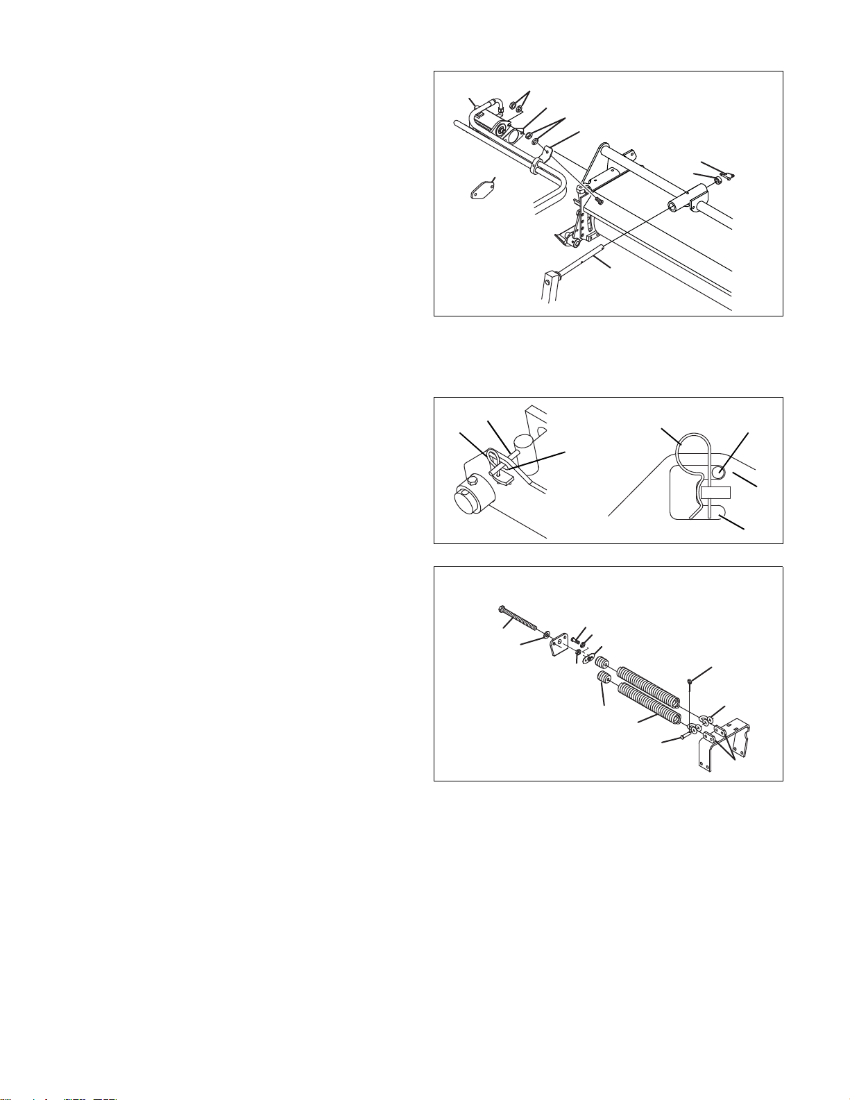
LIFT ARM INSTALLATION (UNITS WITH 30” REELS OR UNITS WITHOUT EXISTING REELS ___________________
J
1. Assemble lift arms (J) to the mower
a. Remove nut and bolt (K) then remove pin (L).
b. Place lift arm (J) in cradle and slide pin (L) through
the cradle and lift arm. Secure pin with hardware
(K).
c. Assemble shackles (N) to the chains then assemble
each chain to crank (M). Secure with pins (P).
d. Assemble free end of chain to lift arm (J) and
secure with pins (P).
e. Repeat Steps a-d for the other side.
DO NOT assemble Down Pressure Springs. They will be
installed after vertical mowers.
L
K
J
K
Figure 1
M
N
P
J
Figure 2
FRONT MOWERS _________________________________________________________________________________
1. Remove the left and right mower assemblies from the
shipping crates. Remove hardware (H) from lift arm (J).
2. Assemble the front mowers to the lift arms with
hardware (H).
3. Remove the cover plate (S) from the drive end of each
mower. Retain hardware (U) and gasket (R). Store
cover plate (S) for future use.
4. Install motors on mowers with hardware (U) and
gasket (R). Nut (T) must be facing upwards as shown.
R
U
S
T
Figure 3A
Figure 3B
3
Page 4
CENTER (REAR) MOWER___________________________________________________________________________
A
B
C
D
C
B
A
1. Remove center mower from its shipping crate and
position behind the rear lift arm (Z). Slide the mower onto
the lift arm and secure with collar (V) and spring clip pin
(W).
2. Remove the cover plate (S) from the drive end of center
mower. Retain hardware (U) and gasket (R). Store cover
plate (S) for future use.
3. Install motor on cutting unit with hardware (U) and
gasket (R). Nut (T) must be facing upwards as shown.
4. Secure hose bracket (X) to stud of center mower with
3/8-16 hardware (Y).
DOWN PRESSURE SPRINGS (UNITS WITH 30” MOWERS AND UNITS WITHOUT EXISTING MOWERS ___________
1. Start the engine and fully raise the lift arms.
2. Stop the engine and lock the arms in transport position.
a. Remove pin (A) and slide handle (B) from the top slot
(C) to the bottom slot (D).
T
U
R
Y
X
S
Z
W
V
Figure 3
b. Insert pin (A) to lock handle (B) in place.
Note: To prevent damage to the mower, the transport
lock must be disengaged before the cutting units can be
lowered.
3. Assemble plug (H) into each spring (J).
4. Assemble 3/8-16 x 1” bolt (E), lockwasher (F) and plate
(G) as shown. [Figure 5]
5. Assemble 1/2-13 x 10” bolt (P), flat washer (Q) and nut
(R) as shown. Thread bolt (P) at least 1-1/2” into plate
(G).
6. Manually raise the front lift arms as far as possible then
tether the arms together.
7. For 26 in. cutting units assemble shackles (K) to each tab
(M) and secure with clevis and cotter pin (L).
8. Connect springs (J) to shackles (K) then remove tethers
and transport lock.
9. Adjust down pressure. [See Parts & Maintenance]
P
Q
R
E
Figure 4
F
G
L
K
H
J
L
M
Figure 5
4
Page 5
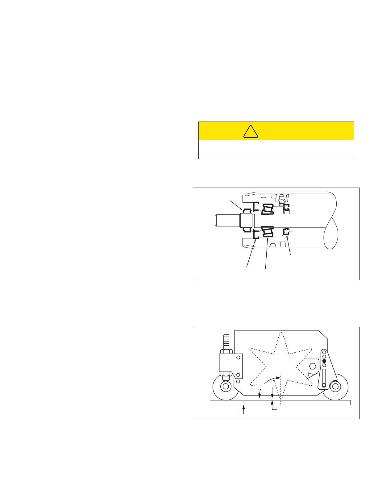
OPERATION________________________________________________________________________________________
!
A
B
C
D
+
Desired Depth
Gauge
Rear
Roller
Front
Roller
90˚
1. The vertical mowers operate in forward rotation allowing
each blade tip to break (cut) new turf and therefore
requires more power than normal mowing.
a. Do not operate the vertical mowers when the
hydraulic reel motors are loaded to a point where
they stall or slow down.
b. The operator must adjust the ground speed to
accommodate for the cutting conditions and power
requirements.
c. If the mower slows down under load, it is an
indication that the cut may be too deep.
2. The vertical mowers were designed to mow at depths of
1/8 to 1/4” (3.2 - 6.4 mm) above the roller, depending on
turf conditions and operations being performed. A greater
cutting depth may damage the root structure and
increase power requirements. It is recommended to begin
with a higher setting and gradually lower blades until
desired results are obtained.
ROLLERS __________________________________________________________________________________________
1. When replacing the bearing (A) the cup and cone should
be replaced in sets. Hand pack each bearing cone with a
good grade of multi purpose Moly 2 EP grease.
2. To remove the bearing cup use a blind hole bearing
puller.
3. When installing the seals (B and C) be sure the lip is
towards the center of the roller.
4. After complete reassembly of the roller tighten locknut (D)
to 10 - 30 ft./lbs. to seat bearings. Readjust locknut to
develop 3 to 7 in./lb. rotational torque resistance on shaft.
Check torque resistance of roller after 25 - 50 hours of
operation and every 250 hours after that.
5. If lubricant inside of roller has been flushed during
disassembly, apply 15 - 20 pumps of multi purpose Moly
2 EP grease with a hand gun into fitting after roller has
been reassembled.
a. Grain control (light and frequent operation) - half of
normal cutting height.
d. Thatch removal (every 60 to 90 days) - 1/8” to 1/4”
setting.
e. Renovation (heavy thatch removal) - not
recommended with Tri-King vertical mowers.
3. Vertical mowing is an operation that can create a lot of
dust and debris. Special care must be taken to clean the
air intake system on the Tri-King at regular intervals.
Check the air intake system if the water temperature
gauge (Diesel Units) indicates an elevated temperature
level.
CAUTION
To prevent contamination of the engine compartment, do
not operate the mowers in reverse rotation.
Figure 6
CUTTING DEPTH ADJUSTMENT _______________________________________________________________________
1. To achieve the desired depth of cut, place an adjusting
gauge at either end of the cutting unit across the two
rollers as shown. [Figure 3]
2. Adjust the cutting depth of the blade with the rear
adjusting nuts. For most applications front adjusters
should be positioned with the top bolt passing through the
second hole from bottom as shown. [Figure 7]
a. Turn the end blade so that one tooth of the blade is at
90 degrees to the top of the gauge as shown.
b. The blades should be adjusted to be at the same
depth at both ends of the cutting unit. [within 1/64”
3. The ground line should be close to parallel with the
(.4mm) inch]
bottom of the mower frame to assure proper cutting and
discharge angle. As the blade wears the front adjuster
can be repositioned to allow proper cutting angle and
depth.
Figure 7
5
Page 6
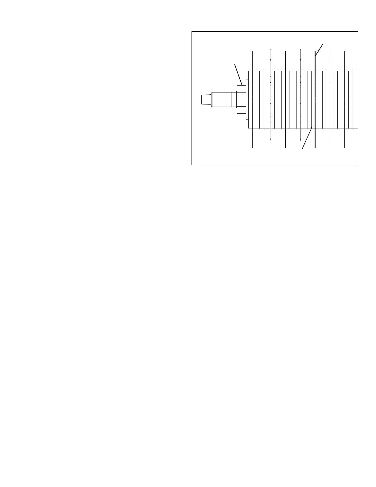
ADDING, REMOVING OR REPLACING BLADES ________________________________________________________
B
C
D
1. Blades may be replaced without removing the cutting unit
from the frame.
2. Loosen blade nut (B) from 1/4” to 3/8” (6.3 to 9.5 mm)
towards the frame.
a. Pull spacer (C) next to the blade (D) to be removed
toward the nut to disengage it from the locking lugs
on the spacer.
b. Remove blade from the shaft. Install replacement
blade with the slot in blade in same position as blade
that was removed and retighten nut (B) securely.
(Torque nut to 12-15 ft. lb. (16-20 N.m)
3. Blade spacing can be adjusted for different modes of
operation, from 1/2” (13 mm) to 1-1/2” (32 mm) in 1/4”
increments (6 mm).
a. 1” (25 mm) spacing between blades is the standard
factory setting.
b. 3/4” (19 mm) to 1-1/2” (38 mm) spacing is
recommended for fairways, greens surrounds and
sport fields.
c. 3/4” (19 mm) to 1” (25 m) spacing is recommended
for tee tops.
Figure 8
6
Page 7

MAINTENANCE _____________________________________________________________________________________
!
!
a. Keep the mower clean and all moving parts properly
WARNING
Before you clean, adjust, or repair this equipment, disengage
all drives, lower cutting units to the ground, engage parking
brake, stop engine, remove key from switch and disconnect
battery to prevent injuries
Proper adjustments and regular maintenance are essential to the
performance of your machine. If proper adjustment cannot be
made, contact an Authorized Jacobsen Dealer.
1. Inspect your machine on a regular basis and replace
worn or damaged parts before operating machine or
before actual breakdown occurs.
2. Establish a regular maintenance schedule.
3. Wash the unit after each use.
4. Clean all plastic or rubber trim with a mild soap solution
5. Repair damaged metal surfaces and use Jacobsen
adjusted.
b. Keep shields in place and all hardware securely
tightened.
CAUTION
Do not wash any portion of the equipment while it is hot.
Do not use high pressure spray or steam. Use cold water
and automotive cleaners.
or use commercially available vinyl/rubber cleaners.
Orange touch-up paint.
Support ___________________________________________________________
If you encounter any problems while installing this kit,
contact your Jacobsen Dealer or contact the Jacobsen
Customer Care department.
7
Jacobsen, A Textron Comany
11108 Quality Drive
Charlotte, NC 28273
800-848-1636
http://www.Jacobsen.com
Page 8
4
3
2
9
33
34
35
24
30
31
8
7
6
5
27
13
18
19
20
20
21
21
21
22
23
29
26
36
32
25
28
12
13
11
10
2
3
4
6
5
1
14
15
16
17
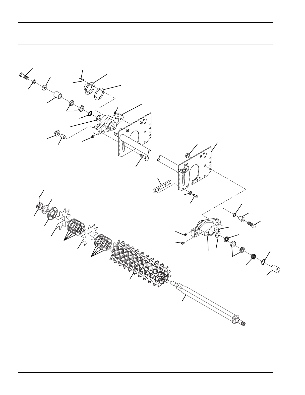
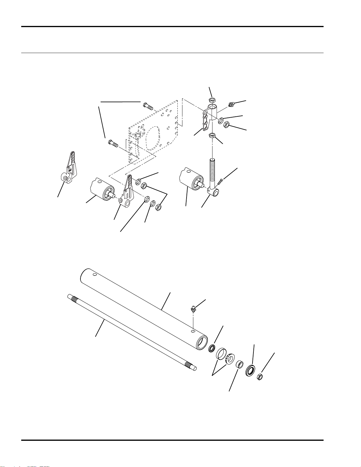
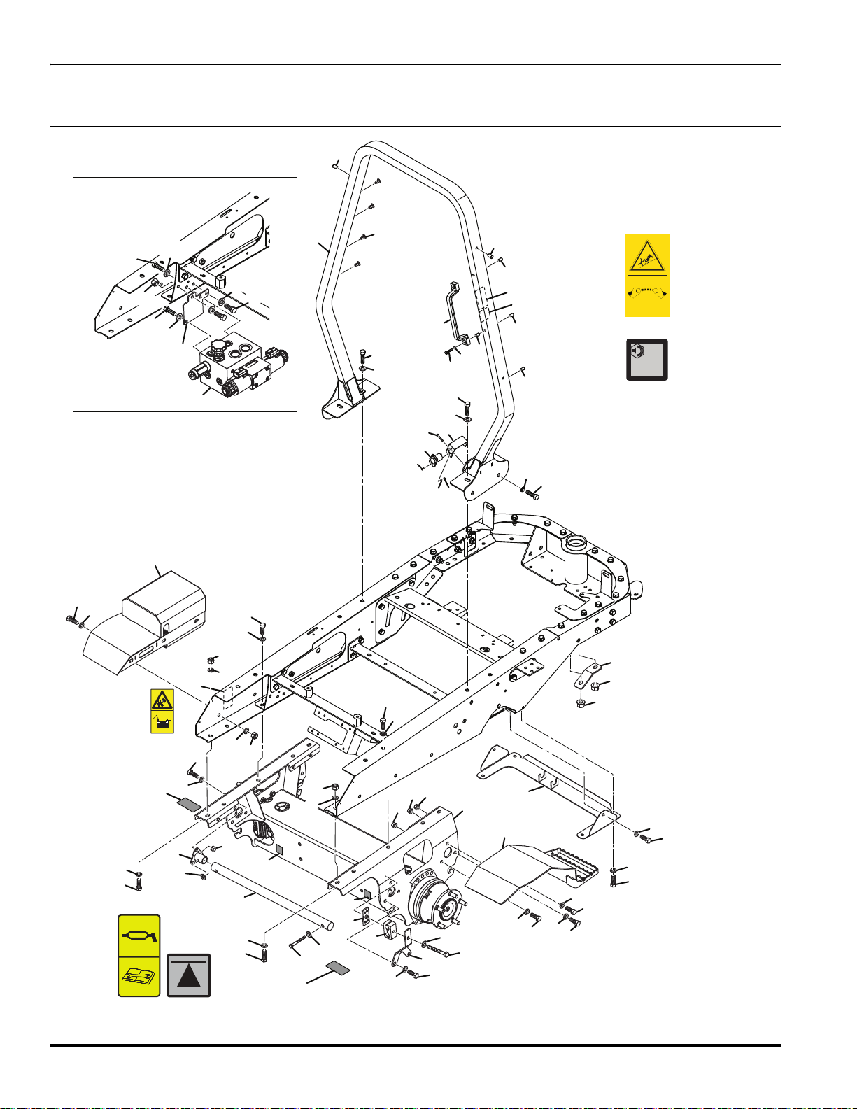
TRI-KING VERTICAL MOWER
1.1 Bearing Housing
Serial No. All
8
Page 9

TRI-KING
Item Part No. Qty. Description Serial Numbers/Notes
1
2 500596 2 • Bearing, Cup and Cone
3 3000983 1 • Oil Seal
4 3001152 1 • Washer
5 471214 1 • Grease Fitting
6 471242 1 • Relief Fitting
7 5001607 1 Motor Housing (Includes 2 ~ 6 and 8)
8 3003086 2 • Stud
9 364148 1 Compression Spring
10 364283 1 Tube, Spacer
11 364259 1 Washer, Bearing Retainer
12 400264 1 Screw, 3/8-16 x 1-1/4” Hex Head
13 446142 5 Lockwasher, 3/8 Hvy
14 364147 1 Gasket, Cover
15 338585 1 Cover
16 446116 4 Lockwasher, #10
17 434038 4 Screw, #10-24 x 1/2”
18 2812091 1 Vertical Reel Assembly
19 2812090 1 • Shaft
20 2812086 22 • Blade
21 3007137 86 • Spacer, Blade
22 2812085 1 • Collar
23 348576 1 • Nut, 1-3/4 - 5 Hex
24 415522 1 • Set Screw, 5/16-18 x 3/8” Soc Hd
25 4112881 2 Carriage Bolt, 5/8-11 x 2”
26 4112921 2 Nut, 5/8-11 Spiralock Flange
27 400258 4 Screw, 3/8-16 x 3/4” Hex Head
28 364282 1 Support Plate
29 4112882 2 Spacer
30 3003389 2 Housing, Pivot Bushing
31 400446 2 Screw, 1/2-20 x 2” Hex Head
32 445789 2 Nut, 1/2-20 Spiralock
33 458039 1 External Snap Ring
34 503684 1 Motor Coupler
35 364151 2 Wave Washer
36 1001643 1 Frame
5001606 1 Housing
> Change from previous revision
9
Page 10
TRI-KING VERTICAL MOWER
13
10
10
20
11
19
17
15
17
13
10
14
18
16
12
7
4
8
9
1
1
5
2
6
3
2.1 Rollers
Serial No. All
10
Page 11

TRI-KING VERTICAL MOWER
Item Part No. Qty. Description Serial Numbers/Notes
1
2 3005156 2 • Wear Sleeve
3 3004882 2 • Oil Seal
4 338647 2 • Oil Seal
5 500534 2 • Bearing, Cup and Cone
6 367029 2 • Nut
7 471214 2 • Grease Fitting
8 N/S 1 • Tube, Roller
9 3003415 1 • Shaft, Roller
10 446142 8 Lockwasher, 3/8 Hvy
11 3008359 1 L.H. Front Roller Bracket
12 3008360 1 R.H. Front Roller Bracket
13 443110 8 Nut, 3/8-16 Hex
14 471214 2 Grease Fitting
15 3007673 2 Housing
16 132680 2 Rear Roller Adjuster
17 3000313 4 Adjusting Nut
18 412015 4 Set Screw, 5/16-18 x 5/8”
19 400264 8 Screw, 3/8-16 x 1-1/4” Hex Head
20 366653 2 Washer
132639 2 Roller
> Change from previous revision
11
Page 12
12
11
10
28
13
24
25
10
8
7
6
4
12
11
10
9
19
18
18
17
20
21
6
5
15/16
27
26
26
22/23
20
31
13
11
3
2
29
11
30
11
12
14
1
1
25
(67141)
25
(67139)
25
(67141)
25
(67140)
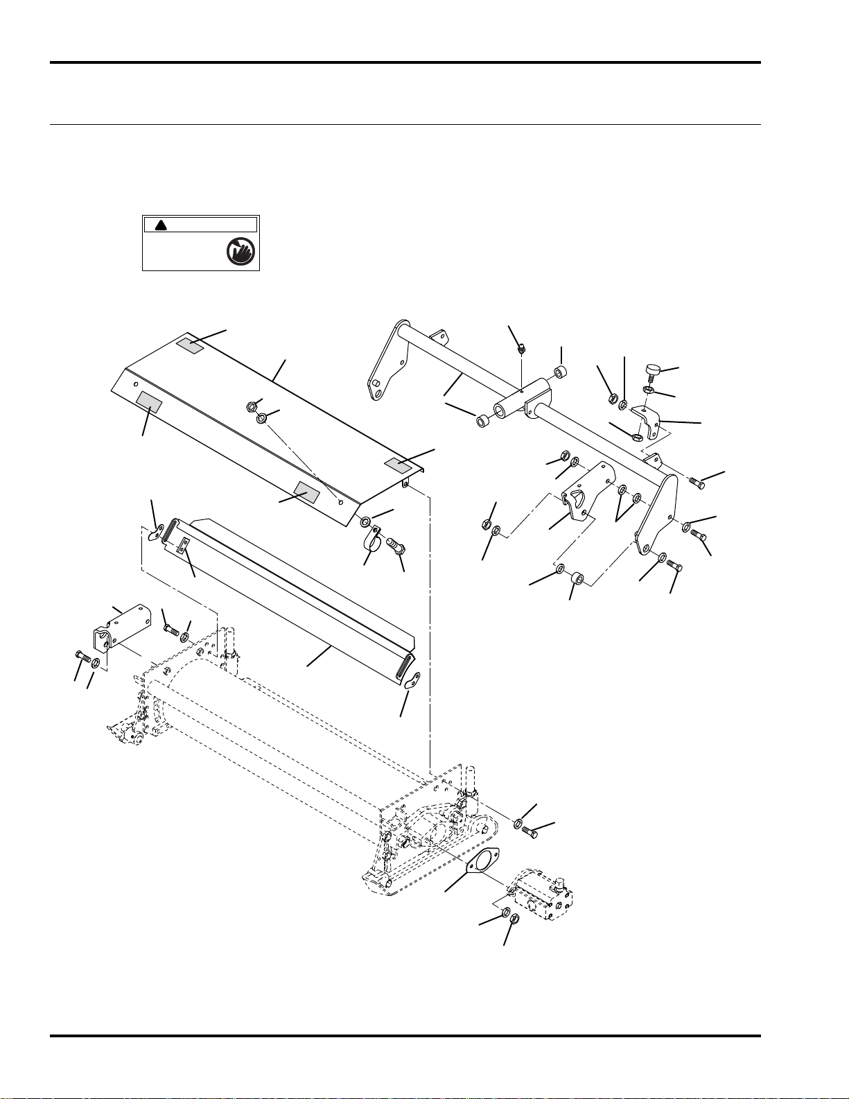
To prevent injury, disengage
all drives, engage parking
brake and stop engine before
working in machine or
emptying grass catchers.
!
DANGER
TRI-KING VERTICAL MOWER
3.1 Shields and Pivot Arm
Serial No. All
12
Page 13

TRI-KING VERTICAL MOWER
Item Part No. Qty. Description Serial Numbers/Notes
1
1 116849 1 Right Pivot Arm 67140 Only
1 1000848 1 Center Pivot Arm 67141 Only
2 338561 1 Reel Pivot Bracket
3 338562 1 Reel Pivot Bracket
4 364302 2 Pivot Spacer
5 400408 2 Screw, 1/2-13 x 1-1/2” Hex Head
6 452012 4 Flat Washer, 1/2
7 446154 2 Lockwasher, 1/2 Hvy
8 443118 2 Nut, 1/2-13 Hex
9 400264 2 Screw, 3/8-16 x 1-1/4” Hex Head
10 453011 AR Washer, 3/8
11 446142 12 Lockwasher, Hvy
12 443110 6 Nut, 3/8-16 Hex
13 400260 6 Screw, 3/8-16 x 7/8” Hex Head
14 471214 1 Grease Fitting
15 3002813 1 Reel Bumper Bracket (Shown) 67141 Only
16 3002814 1 Reel Bumper Bracket 67141 Only
17 361723 2 Rubber Bumper 67141 Only
18 443810 4 Nut, 3/8-16 Jam 67141 Only
19 400190 4 Screw, 5/16-18 x 1-1/4” Hex Head 67141 Only
20 446136 4 Lockwasher, 5/16 Hvy 67139 and 67140 Only
20 446136 8 Lockwasher, 5/16 Hvy 67141 Only
21 443106 4 Nut, 5/16-18 Hex 67141 Only
22 122875.6 1 Rear Shield (Front Mowers) 67139 and 67140 Only
23 1003056.6 1 Rear Shield (Rear Mower) 67141 Only
24 5003650 1 Shield
25 361877 AR • Decal, Danger
26 3000718 2 Shield Shim
27 364281 2 Backup Nut
28 364150 2 Clamp
29 364777 1 Gasket
30 400258 2 Screw, 3/8-16 x 3/4” Hex Head
31 400186 4 Screw, 5/16-18 x 7/8” Hex Head
116850 1 Left Pivot Arm 67139 Only
364156 2 • Bushing 67139 Only
364156 2 • Bushing 67140 Only
364140 2 • Bushing 67141 Only
> Change from previous revision
13
Page 14

Jacobsen, A Textron Company
11108 Quality Drive, Charlotte, NC 28273
www.Jacobsen.com
800-848-1636
Equipment from Jacobsen is built to exacting
standards ensured by ISO 9001 and ISO 14001
registration at all of our manufacturing locations.
A worldwide dealer network and factory trained
technicians backed by Jacobsen Parts Xpress
provide reliable, high-quality product support.
When Performance Matters.
™
Page 15

WARNING
Warning: If incorrectly used, this machine can
cause severe injury. Those who use and maintain
this machine should be trained in its proper use,
warned of its dangers, and must read the entire
manual before attempting to set up, operate, adjust,
or service the machine.
When Performance Matters.
™
677799-Rev A
Parts Manual
Jacobsen TR320 Ride on Cylinder Trim Mower
68021-B000 – TR320, Kubota® D1105-E4B, 3WD, Trea
ded Tires
68021-B100 – TR320, Kubota® D1105-E4B, 3WD, Treaded Tires
68021-B200 – TR320, Kubota® D1105-E4B, 3WD, Treaded Tires
GB
Page 16
CHARLOTTE, NC PRODUCT OF U.S.A.
®
A Textron Company
FOREWORD
This manual contains adjustment, maintenance,
troubleshooting instructions and parts list for your new
Jacobsen machine. This manual should be stored with
the equipment for reference during operation.
Before you operate your machine, you and each operator
you employ should read the manual carefully in its
entirety. By following the safety, operating and
maintenance instructions, you will prolong the life of your
equipment and maintain its maximum efficiency.
If additional information is needed, contact your
Jacobsen Dealer.
The serial plate is located on the left rear frame rail.
Jacobsen recommends you record these numbers below
for easy reference.
Suggested Stocking Guide
To Keep your Equipment fully operational and productive, Jacobsen suggests you maintain a stock of the more
commonly used maintenance items. We have included part numbers for additional support materials and training aids.
To order any of the following material:
1. Write your full name and complete address on your
order form.
2. Explain where and how to make shipment:
❑
UPS ❑ Regular
❑Overnight ❑2nd Day
Mail
3. Order by the quantity desired, the part number, and
the description of the part.
4. Send or bring the order to your authorized Jacobsen
Dealer.
Qty. Part No. Description Qty. Part No. Description
4113986
5000913 Element, Engine Air Filter 4176550 Engine Fan Belt
550489 Cartridge, Engine Fuel Filter
2811255 Charge Filter
Engine Oil Filter 4283654 Ignition Key
Service Support Material
Qty. Part No. Description
677802
677799
TBD Service Manual
This manual may not re repr oduced in whole or in part without the
express permission of TSV (Augusta) Technical Communications
2
Safety & Operation Manual
Parts Manual
Copyrighted Material
Department.
Qty. Part No. Description
Diesel Engine Parts Manual
Proposition 65 Warning
This product contains or emits
chemicals known to State of California
to cause cancer and birth defects or
other reproductive harm.
02-2018
Service Parts
Page 17

Table of Contents
1
1.1......... Operator Platform ............................................... 4
1.1......... Seat Option .......................................................... 1
3.1......... Armrest and Control Panel ................................ 8
4.1......... Traction Pedal ................................................... 10
5.1......... Traction Linkage ............................................... 12
6.1......... Chassis .............................................................. 14
7.1......... Front Axle Assembly ........................................ 16
8.1......... Front Axle .......................................................... 18
9.1......... Rear Axle Assembly ......................................... 20
10.1....... Rear Axle ........................................................... 22
11.1....... Air Filter ............................................................. 24
12.1....... Radiator ............................................................. 26
13.1....... Remote Engine Oil Cooler and Filter .............. 28
14.1....... Engine Mounting ............................................... 30
15.1....... Engine and Pumps............................................ 32
16.1....... Engine Exhaust ................................................. 34
17.1....... Fuel Tank and Routing ..................................... 36
18.1....... Hydraulic Tank and Hood................................. 38
19.1....... Hydraulic Valve Assembly ............................... 40
20.1....... 3WD Traction Hydraulics ................................. 42
21.1....... 3WD Gear Pump and Steering Hydraulics...... 44
22.1....... Front And Rear Reel Hydraulics...................... 46
23.1....... Front And Rear Lift Hydraulics ........................ 48
24.1....... Drain Hydraulics ............................................... 50
25.1....... Brake Valve and Charge Hydraulics ............... 52
26.1....... Oil Cooler Hydraulics ....................................... 54
27.1....... Electrical ........................................................... 56
28.1....... Mounting And Lift Arms .................................. 58
29.1....... Pivot Arms ......................................................... 60
30.1....... Inner Reel Assembly......................................... 62
31.1....... Outer Reel .......................................................... 64
32.1....... Roller Brackets and Skids................................ 66
33.1....... Standard Unit Fixing ......................................... 68
34.1....... Grass Catcher ................................................... 70
35.1....... Brake Valve....................................................... 72
36.1....... Reel Valve .......................................................... 73
37.1....... Lift-Weight Transfer Valve ............................... 74
38.1....... Reel Motor ......................................................... 75
39.1....... Steering Cylinder .............................................. 76
40.1....... Front Lift Cylinder ............................................. 78
41.1....... Rear Lift Cylinder .............................................. 79
42.1....... Steering Valve ................................................... 80
43.1....... Gear Pump ......................................................... 82
44.1....... Traction Pump ................................................... 84
44.1....... Traction Pump (Continued).............................. 86
45.1....... 3WD Rear Wheel Motor .................................... 88
46.1....... Electrical Schematic ......................................... 90
47.1....... Hydraulic Schematic......................................... 94
Page 18
TR320
1
1
1
1
2
3
4
4
5
5
5
6
6
7
8
9
10
10
11
12
12
13
14
31
15
16
16
17
17
18
19
20
20
21
21
27
27
26
26
28
28
29
29
22
23
23
24
25
4397486
®
3008682
4181865 REV B
3
30
32
14°+
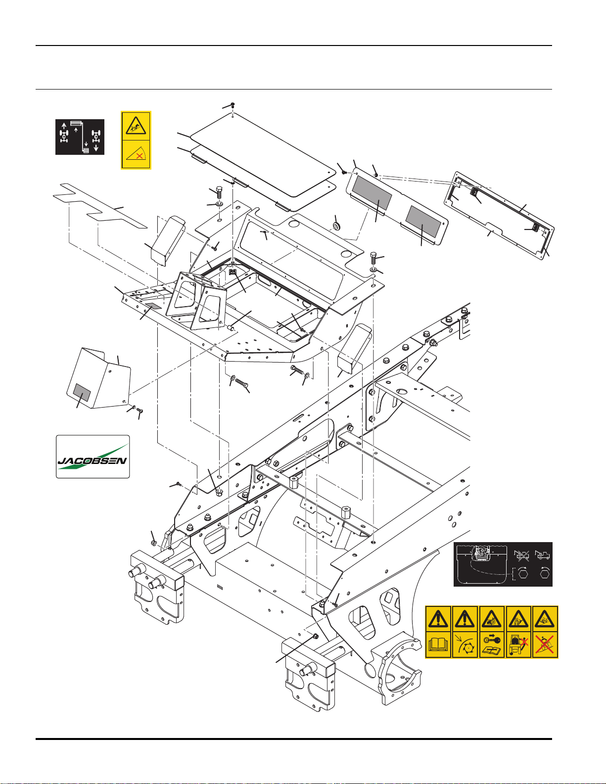
1.1 Operator Platform
Serial No. All
009114550
4
Page 19

TR320
Item Part No. Qty. Description Serial Numbers/Notes
1
2 001496150 16 Pop Rivet, 3.2 x 10 mm Stainless Steel
3 4314427 4 1/4 Turn Fastener
4 4314429 4 1/4 Turn Steel Retainer
5 4314430 4 1/4 Turn Receptacle
6 4394747 2 Cover, Chassis End
7 671357 1 Platform, Operator
8 4395663 1 Cover, Steering Tower
9 671682 1 Adhesive Foam, 578 mm
10 4395665 2 Adhesive Foam, 3 x 4 x 90 mm
11 4395666 1 Adhesive Foam, 4 x 5 x 529 mm
12 4395667 2 Adhesive Foam, 3 x 5 x 202 mm
13 671556 1 Plate, Rear Backing
14 671585 1 Panel, Rear Service
15 4395869 1 Panel, Floor Service
16 450029 4 Hex Head Screw, M10-1.5 x 35 mm
17 450241 4 Hex Head Screw, M12-1.75 x 30 mm
18 450357 4 Nut, M6-1 Insert (0.7 to 4.2)
19 450389 4 Washer, M6 x 12.5 x 1.8
20 450391 4 Washer, M10 x 21 x 2.2
21 450392 4 Washer, M12 x 24 x 2.7
22 450541 4 Pan Head Screw, M6-1 x 16 mm
23 452437 4 Nut, M10-1.5 Flange Nyloc
24 452438 2 Nut, M12-1.75 Flange Nyloc
25 002953223 3 Grommet, 20.6 x 31.8 x 9.5 mm
26 4397486 1 Decal, Traction Pedal
27 669813 1 Decal, Jacobsen Decal
28 4181865 1 Decal, Mower Warning
29 3008682 1 Decal, Tow Valve
30 4420394 1 Floor Board Grip Tape
31 4420395 1 Access Panel Grip Tape
32 009114550 1 Decal, Max Slope 14 Deg
001191331 4 Screw, M5-0.8 x 16 mm Taptite
> Change from previous revision
5
Page 20

TR320
1.1 Seat Option
Serial No. All
Standard Seat Option
13
17
13
5
20
26
12
2
17
8
14
16
17
15
21
1
16
11
15
17
3
4
5
9
22
17
20
9
26
13
13
25
27
17
13
13
25
24
23
18
1
7
24
23
18
6
7
19
10
6
Page 21

TR320
Item Part No. Qty. Description Serial Numbers/Notes
1 4202462 1 Standard Seat
2 4204341 1 Bracket, Right Side Seat Belt
3 4205942 1 Spacer, Seat Belt Bracket
4 4256475 1 Bracket, Left Side Seat Belt
5 4257812 1 Seat Belt Includes latch and retractor
6 4376646 2 Boss, Seat Mount
7 4376647 2 Rail, Seat Mounting
8 4376648 1 Armrest Seat Support
9 4378526 2 Support, Standard Seat
10 450120021 4 Nut, 5/16 - 18 Grade 1
11 450190 4 Screw, M8-1.25 x 16 mm Hex Head
12 672483 2 Bracket, Seat Travel Limiter
13 450214 6 Screw, M10-1.5 x 25 mm Hex Head
14 450378 4 Nut, M8-1.25 Hex Nyloc
15 450379 2 Nut, M10-1.5 Hex Nyloc
16 450390 4 Flat Washer, M8 x 17 x 1.8
17 450391 8 Flat Washer, M10 x 21 x 2.2
18 450392 2 Washer, M12 x 24 x 2.7
19 450411 8 Lockwasher, M8 x 12.75 x 2
20 450412 4 Lockwasher, M10 x 15.9 x 2.5
21 4193341 1 Adjuster, Seat Rail
22 4193344 1 Adjuster, Seat Rail with Handle
23 450413 2 Lockwasher, M12 x 17.9 x 2.5
24 450240 2 Screw, M12-1.75 x 25 mm Hex Head
25 450401 2 Washer, M10 x 24 x 2.2
26 4203220 4 Screw, M8-1.25 x 20 mm Square Hd
27 4384346 1 Fuel Tank Strap
> Change from previous revision
2
Page 22
TR320
9
4
5
11
35
22
38
23
24
25
20
16
26
8
3
18
31
33
36
28
21
2
1
6
17
29
37
14
19
15
35
41
33
39
40
42
10
10
7
11
13
34
27
20
30
32
12
10
42
32
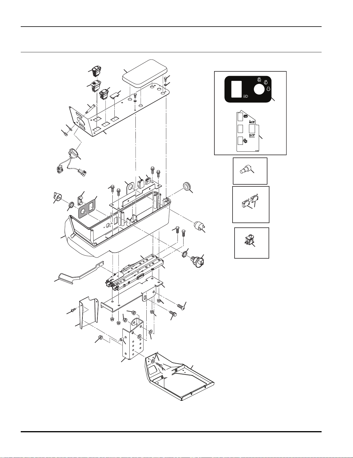
3.1 Armrest and Control Panel
Serial No. All
8
Page 23

TR320
Item Part No. Qty. Description Serial Numbers/Notes
1
2 4193344 1 Adjuster, Seat Rail with Handle Replace handle with Item 4
3 4362366 1 Plate, Armrest Support
4 672316 1 Rod, Armrest
5 4370626 1 Armrest
6 4395147 1 Top Plate, Armrest Support
7 672309 1 Armrest Cover
8 450192 4 Screw, M8-1.25 x 25 mm Hex Head
9 450357 2 Nut, M6-1 Insert (0.7-4.2)
10 450453 4 Nut, M8-1.25 Hex Flange
11 450471 7 Screw, M8-1.25 x 20 mm Hex Flange
12 450541 2 Screw, M6-1 x 16 Grade 4.8
13 2188154 1 Module Delay REFERENCE U4, See 46.1
14 363996 1 Switch
15 4125831 2 Switch, Neutral Proximity
16 4139764 1 Switch, Parking Brake REFERENCE SW6, See 46.1
17 4150539 1 Horn REFERENCE U3, See 46.1
18 4212121 1 LED Indicator
19 4217502 1 Switch, Seat REFERENCE SW3, See 46.1
20 4225220 2 Plug, Panel Refer to Optional Kit
21 4270811 1 Gauge, Fuel/Hourmeter
22 4283269 1 Switch, 3 Position Key REFERENCE SW1, See 46.1
23 4283653 1 • Nut, M22-1.5 Key Switch Backing
24 4283652 1 • Nut, M22-1.5 Key Switch Face
25 4283654 1 • Key, Replacement
26 4324707 1 Switch, Rocker DPDT (MOM)
27 4343926 1 Switch, Yellow Rocker DPDT REFERENCE SW2, See 46.1
28 4381566 1 Pad, Armrest
29 4382209 1 Grommet
30 450168 8 Screw, M6-1 x 12 mm Hex He
1 450331 1 Hex Nut, M8-1.25 Grade 8
3
32 450477 1 Screw, M10 - 1.5 x 20 mm Hex Flange
33 450390 1 Washer, M8 x 17 x 1.
4 15694-65992 1 Lamp Timer REFERENCE U5, See 46.1
3
35 4374506 1 Decal, Key Switch
36 4395054 1 Control Panel, Standard Steel
37 4391886 1 Decal, Control Panel Standard
38 4376648 1 Armrest Seat Support See 2.1
39 672308 1 Side Bracket, Armrest Support
40 452436 3 Nut, M8 Flange Nyloc
41 450391 5 Washer, M10 x 21 x 2.2
42 4290433 2 Screw, Button Head M10 x 25
43 450379 2 Nut, M10 - 1.5 Hex Nyloc
4193341 1 Adjuster, Seat Rail
ad
8
> Change from previous revision
9
Page 24
TR320
16
1
4
4
5
5
6
7
8
9
10
11
12
28
28
26
14
15
15
23
17
17
27
18
20
20
20
20
21
21
21
22
25
29
39
25
2
3
16
20
15
21
29
16
16
28
17
29
22
25
19
34
38
35
36
37
21
21
13
26
26
27
16
21
24
24
31
32
30
31
33
29
29
29
23
16
16
16
21
21
16
22
27
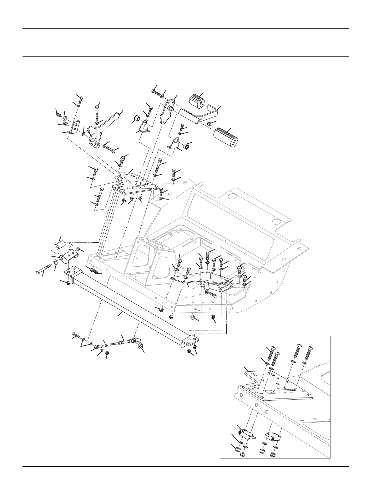
4.1 Traction Pedal
Serial No. All
10
Page 25

TR320
Item Part No. Qty. Description Serial Numbers/Notes
1
2 3003474 1 Grip, Reverse Pedal
3 3003475 1 Grip, Forward Pedal
4 4185740 2 Bracket, Pedal Pivot
5 4185741 1 • Bearing, 1/2” Self Align
6 4200040 1 Screw, M12 - 1.75 Detent
7 4367106 1 Traction Lever
8 4377786 1 Lever, Mow Speed Stop
9 4377886 1 Bracket, Mow Speed Lever
10 4378832 1 Pedal
11 4382867 1 Roller Weldment Bracket, RH
12 450001 1 Hex Bolt, M6 - 1.0 x 30 mm
13 450014 2 Screw, M8-1.25 x 30 mm Hex Head Grade 8.8
14 450020231 1 Nut, 1/4-28 Thin Hex
15 450172 6 Screw, M6-1 x 25 mm Hex Head
16 450192 17 Screw, M8-1.25 x 25 mm Hex Head
17 450324 3 Nut, M8-1.25 Hex
18 450333 1 Nut, M12-1.75 Thin Hex
19 450377 1 Nut, M6 - 1.0 Hex
20 450389 9 Washer, M6 x 12.5 x 1.8
21 450390 19 Washer, M8 x 17 x 1.8
22 452435 6 Nut, M6-1 Flange Nyloc
23 452437 4 Nut, M10 Flange Nyloc
24 4397147 1 Roller Weldment Bracket, LH
25 4398009 1 Buffer Brace Weldment
26 450029 4 Hex Bolt, M10 - 1.5 x 35 mm
27 450391 4 Washer, M10 x 21 x 2.2
28 450198 3 Screw, M8 - 1.25 x 55 mm Hex Head
29 452436 18 Nut, M8 Flange Nyloc
30 4125831 2 Switch, Proximity
31 450386 8 Washer, M3 x 7 x 0.6
32 450511 4 Screw, M3-0.5 x 25 mm Pan Head
33 452716 4 Nut, M3-0.5 Hex
34
35 671673 2 Screw, M16 x 110 mm Hex Head Socket Drive Screw
36 450393 2 Washer, M16 x 30 x 3.3
37 452439 2 Nut, M16-2 Flange Nyloc
38 MBG1642 2 Roller, Wing Unit
39 4368187 1 Cable, Traction See 5.1 for other end of cable
128079 1 Rod End, 1/4-28
Nyloc
4397906 2 Bracket, Bottom Roller
> Change from previous revision
11
Page 26
TR320
1
2
3
4
5
6
7
8
8
9
22
9
9
9
10
10
10
10
11
12
13
14
15
16
17
17
18
19
20
21
23
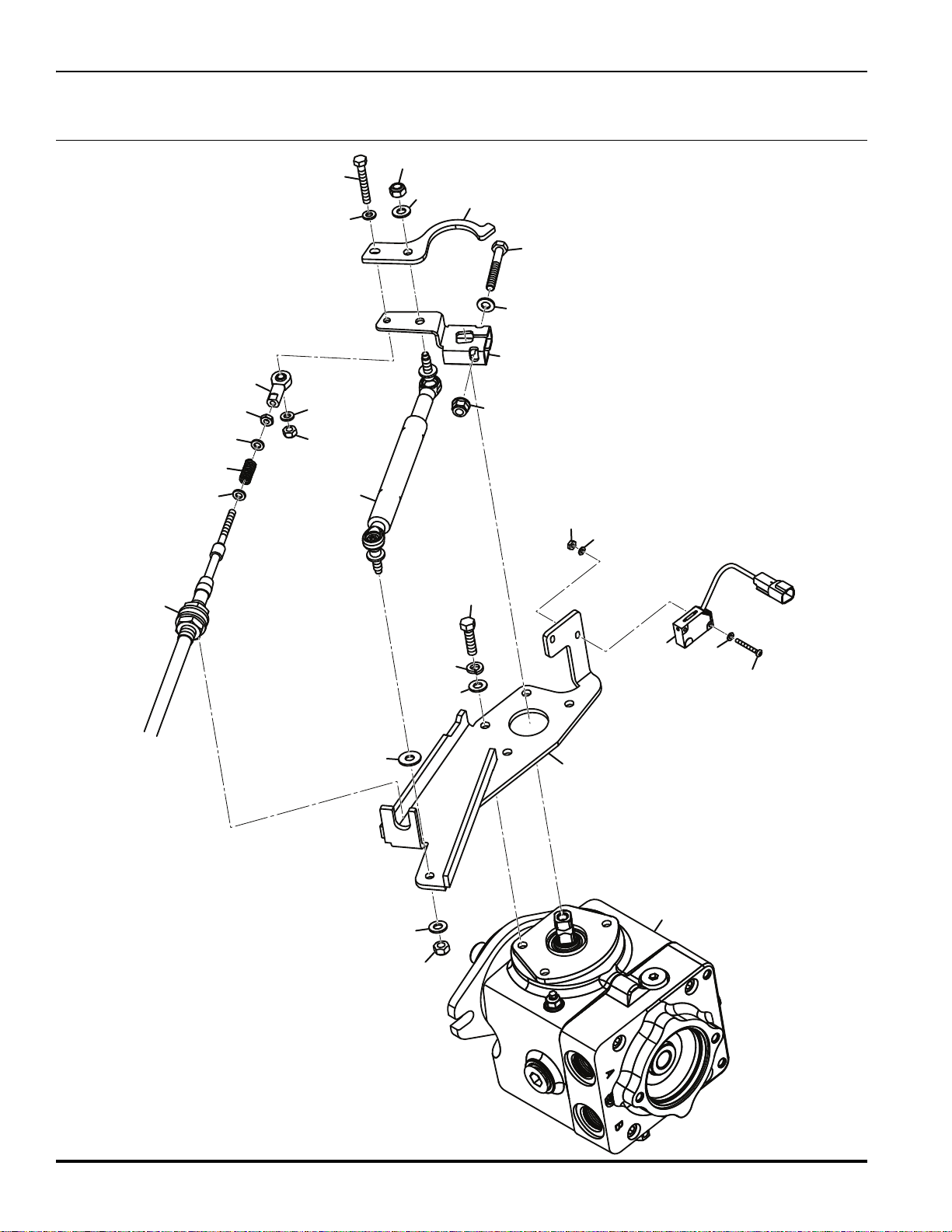
5.1 Traction Linkage
Serial No. All
12
Page 27

TR320
Item Part No. Qty. Description Serial Numbers/Notes
1
2 4125831 1 Switch, Neutral Proximity REFERENCE SW12, See 46.1
3 4368187 1 Cable, Traction See 4.1 for other end of cable
4 4386927 1 Control Arm
5 450019 1 Screw, M8-1.25 x 55 mm Hex Head
6 450192 4 Screw, M8-1.25 x 25 mm Hex Head
7 450020231 1 Nut, 1/4-28 Thin Hex
8 450386 4 Washer, M3 x 7 x 0.6 mm
9 450389 4 Washer, M6 x 12.5 x 1.8
10 450390 7 Washer, M8 x 17 x 1.8
11 450411 4 Lockwasher, M8 x 12.75 x 2
12 450511 2 Screw, M3-0.5 x 25 mm Pan Head
13 450002 1 Screw, M6-1 x 35 mm Hex Head
14 452436 1 Nut, M8-1.25 Flange Nyloc
15 452716 2 Nut, M3-0.5 Hex Nyloc
16 450377 1 Nut, M6-1 Hex Nyloc
17 450378 2 Nut, M8-1.25 Hex Nyloc
18 4397226 1 Plate, Cable Sensor
19 4397230 1 Actuator, Neutral Switch
20 4397526 1 Damper, Self Centering
21 450400 1 Washer, M8 x 21 x 1.8
22 4231340 1 Spring, 11.13 x 1,42 x 25.4
23 4203740 1 Pump, LPV 35 cc Piston See 44.1 for Service Parts
128079 1 Rod End, 1/4”
> Change from previous revision
13
Page 28
TR320
19
20
1
1
1
28
48
1
1
1
2
3
3
4
5
6
7
8
9
10
34
34
44
45
35
35
35
42
36
11
12
14
15
16
17
18
19
19
20
20
20
33
33
20
20
20
20
20
20
20
22
23
23
23
24
24
26
26
26
26
27
28
28
28
28
28
30
31
31
31
31
31
31
31
31
32
46
47
29
4
25
29
13
28
0.7 bar
10 psi
673581
37
28
20
38
39
40
41
41
20
13
29
19
29
43
29
20
28
20
28
20
28
838363
670526
42
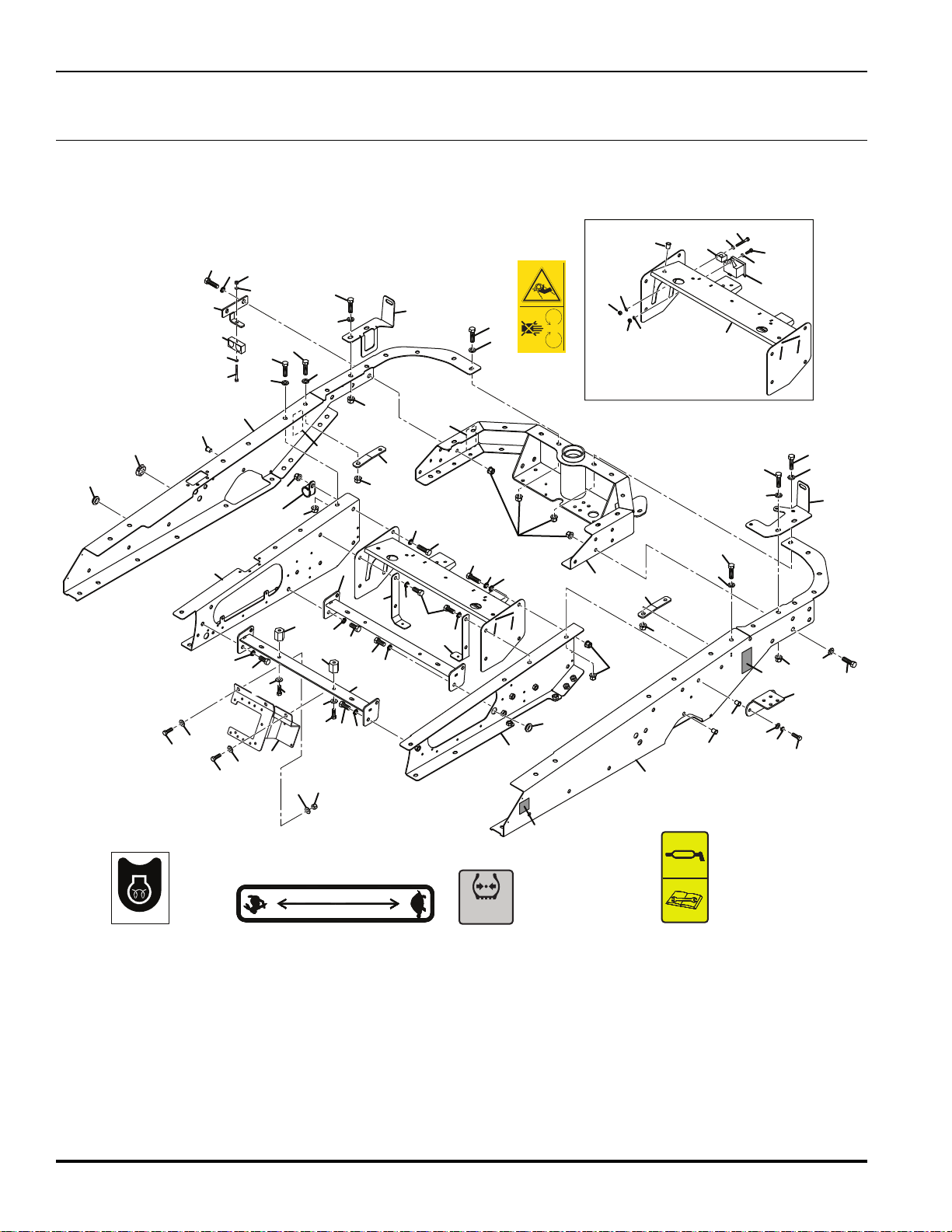
6.1 Chassis
Serial No. All
14
Page 29

TR320
Item Part No. Qty. Description Serial Numbers/Notes
1
2 4309904 1 3 Way Distribution Block
3 4350748 2 Bracket, Angled Brace
4 4350749 2 Cross Brace, Center
5 4362466 1 ROPS Rail, LH
6 4362467 1 ROPS Rail, RH
7 4365086 1 Cross Brace, Radiator
8 4371587 1 Bracket, Charge Filter
9 4393946 1 Rail, RH
10 4393948 1 Rail, LH
11 4375506 1 Bracket, LH Oil Tank
12 4375566 1 Bracket, RH Oil Tank
13 4376646 2 Boss, Seat Mount
14 4386646 1 Chassis, Rear
15 4394346 1 Bracket, Fuse Block & Brake Valve
16 4394471 1 Stauf Clamp
17 450003 1 Hex Head Screw, M6-1 x 40 mm
18 450171 1 Hex Head Screw, M6-1 x 20 mm
19 450214 4 Hex Head Screw, M10-1.5 x 25 mm
20 450242 42 Hex Head Screw, M12-1.75 x 35 mm Grade 8.8
21 450357 1 Insert, M6-1
22 450369 3 Nut, M8-1.25 Insert (0.7 to 3.8)
23 450371 4 Nut, M10-1.5 Insert (0.7 to 3.8)
24 450377 2 Nut, M6-1 Hex Nyloc
25 450379 3 Nut, M10-1.5 Hex Nyloc
26 450389 4 Washer, M6 x 12.5 x 1.8
27 450391 2 Washer, M10 x 21 x 2.2
28 450392 27 Washer, M12 x 24 x 2.7
29 450401 8 Washer, M10 x 24 x 2.2
30 450412 2 Lockwasher, M10 x 15.9 x 2.5
31 452438 29 Nut, M12-1.75 Flange Nylock
32 4139045 1 P-Clip, 1-5/16 Dia
33 4396546 2 Bracket, Tube Clamp
34 673581 1 Decal, Tire Pressure
35 4164580 2 Decal, Lubrication
36 009034900 1 Decal, Belt
37 002953223 1 Grommet, 20.6 x 31.8 x 9.5
38 4398766 1 Bracket, Hose Clamp
39 4398686 1 Clamp, Stauf - LBG-425, 4-PP
40 450005 1 Screw, M6-1 x 50 mm Hex Head
41 450389 2 Washer, M6 x 12.5 x 1.8
42 450377 1 Nut, M6-1 Hex Nyloc
43 450215 3 Screw, M10-1.5 x 30 mm Hex Head
44 838363 1 Decal, Throttle
45 670526 1 Decal, Glow Plug
46 673618 1 Blanking Plug, 38 mm
47 671358 1 Grommet, 38 x 32 mm
48 450413 1 Washer
49 48228-06 1 P-Clip, 1.23” Dia Not illustrated
4273470 15 AV Washer - 13 x 19.5 x 2.5
> Change from previous revision
15
Page 30
TR320
1
7
7
2
3
3
4
4
4
6
8
9
38
10
10
10
11
39
13
14
15
40
31
31
31
17
44
18
19
27
2
2
27
19
19
19
19
19
2
19
19
20
20
21
21
22
21
23
2
32
19
21
31
31
24
21
21
42
28
21
21
21
21
33
33
37
3733
30
34
34
35
35
36
36
21
21
41
37
16
105
dB
L
WA
5
21
31
43
20
Front Axle
26
26
45
47
46
45
12
29
25
7.1 Front Axle Assembly
Serial No. All
16
Page 31

TR320
Item Part No. Qty. Description Serial Numbers/Notes
1
2 4273470 18 AV Washer - 13 x 19.5 x 2.5
3 669479 5 Fir Tree Insert, 13.5 mm
4 4314627 8 Screw, M12-1.75 x 35 mm Hex Head Grade 10.9
5 4370266 1 ROPS
6 4395246 1 Bracket, Socket Mount
7 450402 4 Washer, M12 x 28 x 2.7
8 450192 2 Screw, M8-1.25 x 25 mm Hex Head Torque to 70 ft. lb. (97 Nm)
9 450321 2 Nut, M4-0.7 Hex
10 450357 3 Nut, M6-1 Insert (0.7 to 4.2)
11 450387 2 Washer, M4 x 9 x 0.9
12 452437 2 Nut, M10 Flange Nyloc
13 450532 2 Screw, M5-0.8 x 35 mm Pan Head
14 450594 2 Screw, M4-0.7 x 12 Countersunk
15 843942 1 Outlet, 12 V Accessory REFERENCE U5, See 46.1
16 669503 11 Mouting Button, 6.6 mm
17 4388428 1 Fender and Step
18 4393846 1 Fender and Battery Box
19 450242 22 Screw, M12-1.75 x 35 mm Hex Head
20 450380 6 Nut, M12-1.75 Hex Nyloc
21 450392 32 Washer, M12 x 24 x 2.7
22 450055 4 Bolt, M12-1.75 x 75 mm Hex Head
23 4381048 4 Carrier Support
24 4391327 2 Lower Ch Rail Bracket
25 450391 4 Washer, M10 x 21 x 2.2
26 456110066 2 Screw, 3/8-16 x 1 Hex Head
27 450243 2 Screw, M12-1.75 x 40 mm Hex Head
28 450240 2 Screw, M12-1.75 x 25 mm Hex Head
29 450215 2 Screw, M10-1.5 x 30 mm Hex Head
30 4393546 2 Cross Bar, Chassis
31 452438 20 Nut, M12 Flange Nyloc
32 450018 2 Bolt, M8-1.25 x 50 mm Hex Head
33 4164580 2 Decal, Lubrication
34 009114100 1 Decal, Battery
35 009114380 1 Decal, Seat Belt
36 009034770 1 Decal, Sound
37 4397046 2 Decal, Jacking
38 450370 2 Nut, M8-1.25 Insert
39 450390 2 Washer, M8 x 17 x 1.8
40 2208139 4 Hose Clamp Bottom
41 4122501 2 Bore Hose Clamp, 5/8”
42 450411 2 Lockwasher, M8 x 12.75 x 2
43 4400045 2 Hose Clamp Bracket, Front Unit
44 669323 1 Archway Panel Weldment
45 450412 2 Lockwasher, M10 x 15.9 x 2.5
46 4395186 1 Reel Valve Bracket
47 4355571 1 Reel Valve See 36.1 for Service Parts
4259710 1 Handle, ROPS
> Change from previous revision
17
Page 32
TR320
2
8
4
7
5
6
3
3
3
1
8
8
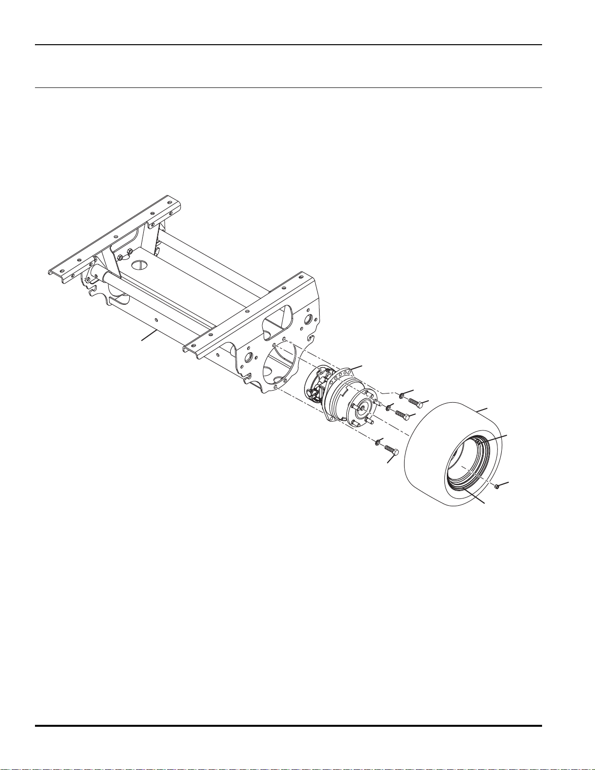
8.1 Front Axle
Serial No. All
18
Page 33

TR320
Item Part No. Qty. Description Serial Numbers/Notes
1
2 4379926 2 Wheel Motor, 235 cc
3 450242 8 Screw, M12-1.75 x 40 mm Hex Head
4
5 4375488 1 • Wheel, 10 x 8.5
6 4220940 1 • Tubeless Tire Valve
7 001341110 5 Nut, 1/2-20 Wheel
8
4a
5
6
4374927 1 Front Axle Weldment
4388026 2 Treaded Wheel and Tire Assembly
4233963 1 • Tire, 20 x 12-10 4 Ply Grassmaster
4273470 8
4375489
4233900
4375488
4220940
AV Washer - 13 x 19.5 x 2.5
2
Smooth Wheel and Tire Assembly
• Tire, 20 x 12-10 2 Ply OTR
1
• Wheel, 10 x 8.5
1
• Tubeless Tire Valve
1
> Change from previous revision
19
Page 34
TR320
1
2
3
4
5
7
6
6
6
8
8
9
9
9
10
10
11
11
11
12
12
13
14
15
16
17
9.1 Rear Axle Assembly
Serial No. All
20
Page 35

TR320
Item Part No. Qty. Description Serial Numbers/Notes
1
2 4391085 1 Gusset, RH Rear Chassis
3 4391106 1 Gusset, LH Rear Chassis
4 4399209 1 Bracket, Rear Motor
5 4273470 1 AV Washer - 13 x 19.5 x 2.5
6 450216 4 Hex Head Screw, M10-1.5 x 35 mm
7 450239 1 Hex Head Screw, M12-1.75 x 20 mm
8 450242 6 Hex Head Screw, M12-1.75 x 35 mm Grade 8.8
9 450391 4 Washer, M10 x 21 x 2.2
10 450392 6 Washer, M12 x 24 x 2.7
11 452437 4 Nut, M10-1.5 Flange Nyloc
12 452438 6 Nut, M12-1.75 Flange Nyloc
13 MBA2397A 1 Washer, 11 x 82 x 3
14 4397266 1 Collar, Rear Axle
15 4397488 1 Ball Bearing, 40 x 80 x 18
16 4397507 1 Nilos Ring
17 REF 1 3WD Rear Axle See 10.1
002036070 1 Ball Bearing, 35 x 72 x 10
> Change from previous revision
21
Page 36

TR320
1
2
3
3
4
5
6
7
8
9
9
9
10
11
12
13
14
25
26
27
15
16
17
18
19
20
21
22
23
24
24
28
9
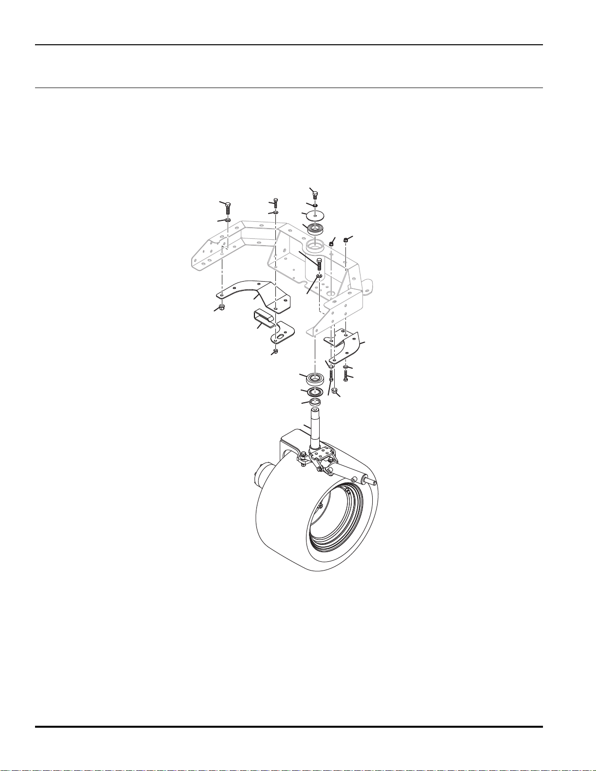
10.1 Rear Axle
Serial No. All
22
Page 37

TR320
Item Part No. Qty. Description Serial Numbers/Notes
1
2 001399032 1 Nut, 1/2-20 Nyloc
3 002143004 4 Bush, 10 x 12 x 10
4 008006260 1 Nut, 1-20 Wheel Motor Torque to 400 ft. lb.
5 008145256 1 Rod End, 1/2-20
6 4183560 1 Screw, M6-1 x 20 mm Hex Socket
7 4192800 1 Hub, Wheel Nut
8 4244289 1 Cylinder, Steering See 36.1 for Service Parts
9 4273470 6 AV Washer - 13 x 19.5 x 2.5
10 4366566 1 Bracket, Journal Mounting
11 4370787 1 Wheel Hub
12 4379887 1
13 4386741 1 3WD Wheel Yoke
14 450020281 1 Nut, 1/2-20 Thin Hex
15 450056 4 Screw, M12-1.75 x 80 mm Hex Head
16 450214 4 Screw, M10-1.5 x 30 mm Hex Head
17 450391 4 Washer, M10 x 21 x 2.2
18 450392 2 Washer, M12 x 24 x 2.7
19 450413 4 Lockwasher, M12 x 17.9 x 2.5
20 450455 4 But, M12-1.75 Hex Flange Grade 10
21 672713 1 Hex Head Screw, 2.1/2 Grade 8
22 4399226 5 Stud, M14-1.5 x 50 mm
23 MBC5942 1 Journal
24 MBC5959A 4 Bolt, 1/2-20 x 12mm
25 4375487 1 • Tire, 20 x 10-10 4 Ply Grassmaster Treaded Tire
26 4375488 1 • Wheel, 10 x 8.5
27 4220940 1 • Tubeless Tire Valve
28 450412 4 Lockwasher, M10 x 15.9 x 2.5
25a
26
27
008008460 5 Nut, M14-1.5 x 34 mm Wheel
3
Motor, 28.7 in
4375486 1 Treaded Wheel and Tire Assembly
1
4375489
4233900
4220940
4375488
1
• Smooth Wheel and Tire Assembly
1
• Tire, 20 x 10-10 2 Ply OTR
1
• Wheel, 10 x 8.5
1
• Tubeless Tire Valve
Wheel
See 45.1 for Service Parts
Smooth Tire
> Change from previous revision
23
Page 38

TR320
1
1
2
3
4
5
6
7
8
10
11
12
9
9
7
12
11.1 Air Filter
Serial No. All
24
Page 39

TR320
Item Part No. Qty. Description Serial Numbers/Notes
1
2 3002365 1 Indicator, Air Cleaner
3 4378166 1 Hose, Air Cleaner Intake
4 4378646 1 Bracket, Air Cleaner
5 4395228 1 Rain Cap Includes Clamp
6 450192 2 Screw, M8-1.25 x 25 mm Hex Head
7 450242 2 Screw, M12-1.75 x 35 mm Hex Head
8 452436 2 Nut, M8-1.25 Flange Nyloc
9 452438 2 Nut, M12-1.75 Flange Nyloc
10 819028 1 Mount, Air Cleaner
11 4395230 1 Air Cleaner
12 450392 2 Washer, M12 x 24 x 2.7
001925570 2 Clamp, 45-60 mm Hose
5000913 1 • Element, Air Filter
5000912 1 • Cover, Assembly
5000914 1 • Valve, Vactuator
> Change from previous revision
25
Page 40

TR320
1
1
2
2
3
4
5
6
7
8
9
9
10
11
12
14
14
24
16
17
18
19
19
20
20
20
20
21
21
21
22
25
25
26
26
22
23
23
23
27
18
009034880
16
21
23
21
15
15
15
13
12.1 Radiator
Serial No. All
26
Page 41

TR320
Item Part No. Qty. Description Serial Numbers/Notes
1
2 108094-06 2 Hose Clamp
3 4123826 1 Expansion Tank
4 4348026 1 Fan, Electric 16 in. PWM REFERENCE M3, See 46.1
5 4399308 1 Shroud, Rear Radiator
6 4359066 1 Hose, Upper Expansion Tank
7 4359067 1 Hose, Lower Expansion Tank
8 4376688 1 Radiator and Hydraulic Oil Cooler
9 4378487 4 Spacer, Fan
10 4385186 1 Bracket, Expansion Tank
11 4399443 1 Shroud, Front Radiator
12 4394906 1 Seal, Radiator Foam
13 450000 1 Screw, M6-1 x 25 mm Hex Head
14 450008 4 Screw, M6-1 x 55 mm Hex Head
15 450191 5 Screw, M8-1.25 x 20 mm Hex Head
16 450192 6 Screw, M8-1.25 x 25 mm Hex Head
17 450323 1 Nut, M6-1 Hex
18 450324 3 Nut, M8-1.25 Hex
19 450357 4 Nut, M6-1 Insert (0.7 to 4.2)
20 450389 6 Flat Washer, M6 x 12.5 x 1.8
21 450390 11 Flat Washer, M8 x 17 x 1.8
22 450410 4 Lockwasher, M6 x 9.6 x 1.5
23 450411 10 Lockwasher, M8 x 12.75 x 2
24 4365086 1 Cross Brace, Radiator
25 009034920 1 Decal, Hot Surface Warning
26 009034880 1 Decal, Fan Warning
27 669996 1 Wiring Bracket
28 48228-06 1 P-Clip Not Shown
001925400 2 Hose Clamp, 19-40 mm
4123828 1 • Pressure Cap, 13 psi
> Change from previous revision
27
Page 42

TR320
1
2
3
4
6
6
9
10
11
13
12
5
8
12
14
14
15
17
16
7
13.1 Remote Engine Oil Cooler and Filter
Serial No. All
28
Page 43

TR320
Item Part No. Qty. Description Serial Numbers/Notes
1
2 4133243 1 • Head, Filter
3 4113986 1 • Cartridge, Oil Filter
4 4398567 1 Fitting, -6 ORFS x M16-1.5 90°
5 450331 2 Nut, M8-1.25 Thin Hex
6 158065-03 2 Fitting, -8 ORFS x 1/2 NPTF Straight Can Use 4186441
7 4399007 1 Hose, Oil Cooler to Filter
8 672486 1 Panel, Radiator Bottom
9 4399008 1 Hose, Filter to Engine
10 4396366 1 Fitting, -6 ORFS x M16-1.5 Straight
11 672598 1 Shroud, Front Radiator
12 2198084 2 • Latch, Swell
13 4399434 2 • Shroud Front
14 4399229 2 Trim, 150 cm
15 450191 2 Screw, M8-1.25 x 20 mm Hex Head
16 450411 2 Lockwasher, M8 x 12.5 x 2
17 450390 2 Washer, M8 x 17 x 1.8
4399316 1 Engine, Kubota D1105-E4B
339909 1 • O-Ring, -6 ORFS
339910 1 • O-Ring, -8 ORFS
339909 1 • O-Ring, -6 ORFS
672591 1 Shroud, Front Assembly
> Change from previous revision
29
Page 44
TR320
1
Part of
Item 1
2
3
4
4
4
5
6
6
6
6
7
7
7
7
7
8
8
8
8
9
9
9
10
10
11
11
11
12
12
13
13
13
13
14
16
15
17
25
9
View Rotated 180° For Clarity
18
26
27
19
19
20
21
22
24
9
16
23
28
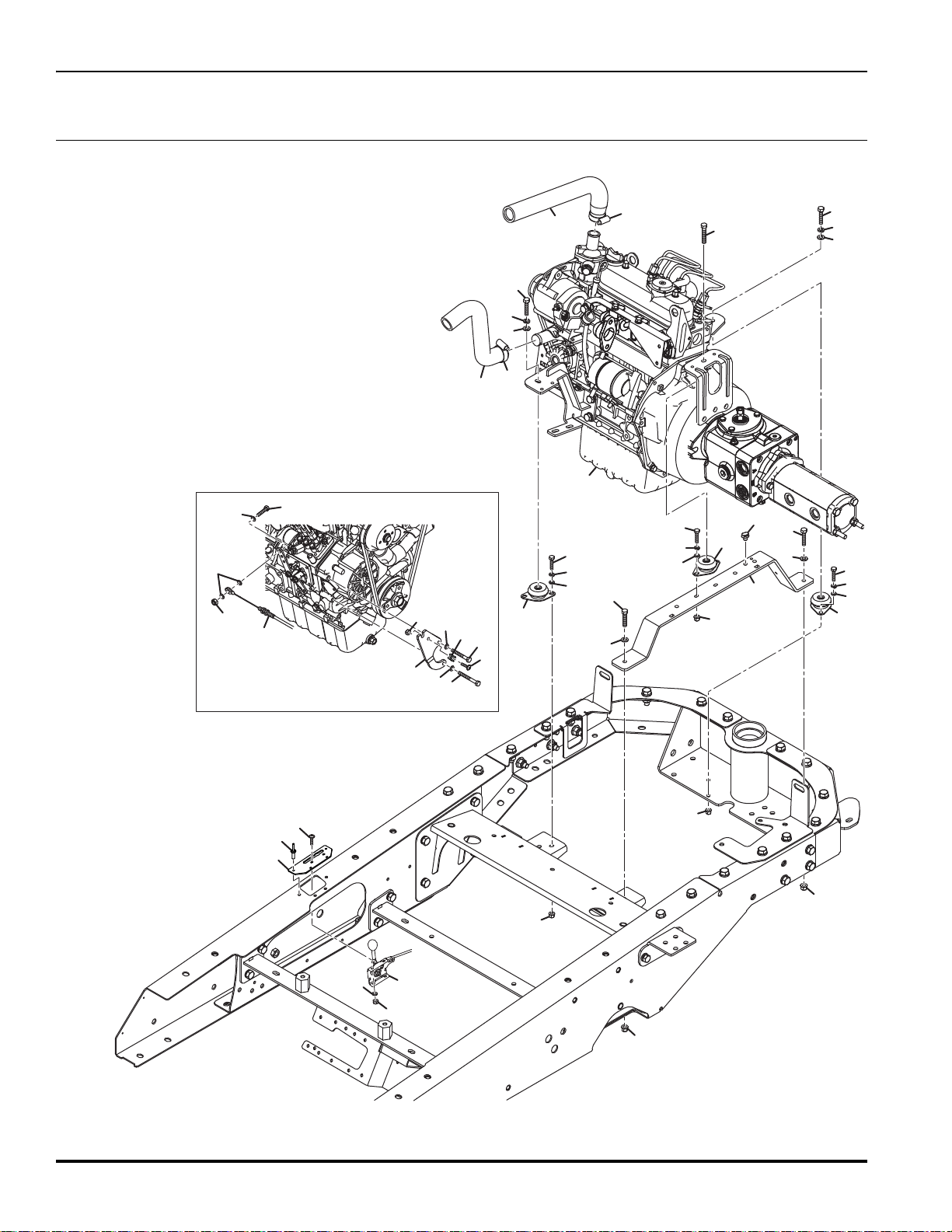
14.1 Engine Mounting
Serial No. All
30
Page 45

TR320
Item Part No. Qty. Description Serial Numbers/Notes
1
2 4244831 1 Hose, Radiator
3 4359048 1 Hose, Upper Radiator
4 4358026 3 Mount, Engine
5 4377767 1 Bracket, Engine Subframe
6 450193 4 Screw, M8-1.25 x 30 mm Hex Head
7 450389 9 Washer, M6 x 12.5 x 1.8
8 450390 4 Washer, M8 x 17 x 1.8
9 450410 8 Lockwasher, M6 x 9.6 x 1.5
10 450411 2 Lockwasher, M8 x 12.75 x 2
11 452435 6 Nut, M6-1 Flange Nyloc
12 452436 2 Nut, M8-1.25 Flange Nyloc
13 450172 7 Screw, M6-1 x 25 mm Hex Head
14 450377 1 Nut, M6-1 Hex Nyloc
15 450388 2 Washer, M5 x 10 x 1.1
16 450376 3 Nut, M5-0.8 Hex Nyloc
17 4393167 1 Plate, Throttle Cable
18 4306557 2 Screw, M5-0.8 Flange Button Head
19 48396 2 Hose Clamp (27-51 mm)
20 450194 1 Screw, M8-1.25 x 35 mm Hex Head
21 450006 1 Screw, M6-1 x 55 mm Hex Head
22 450005 1 Screw, M6-1 x 50 mm Hex Head
23 REF 1 Engine and Pump Assembly See 15.1
24 4395489 1 Connector, FIR Tree mounting
25 450528 1 Screw, M5-0.8 x 16 mm Pan Head
26 4399727 1 Plate, Throttle Cable
27 669840 4 Pop Rivet, 4.8 x 14 mm
28 4370167 1 Mount, Fir Tree Cable Tie
4393088 1 Lever, Engine Throttle
> Change from previous revision
31
Page 46

TR320
1
2
3
4
5
6
7
8
42
10
11
13
13
14
15
16
16
16
16
17
18
17
17
17
17
17
18
19
19
19
21
20
20
20
20
20
20
20
21
22
23
24
24
24
24
25
26
27
28
29
31
32
33
34
35
36
37
38
39
40
22
22
30
17
12
41
15
15.1 Engine and Pumps
Serial No. All
32
Page 47

TR320
Item Part No. Qty. Description Serial Numbers/Notes
1
2 006820550 2 Screw, M10-1.25 x 30 mm Hex Head
3 4395240 1 Coupling, 13 Tooth
4 4203740 1 Pump, LPV 35 cc Piston See 44.1 for Service Parts
5 4399316 1 Engine, Kubota D1105-E4B
6 553842 1 • Screw, M6 x 50 mm
7 4396226 1 Mount, Engine
8 4377606 1 Mount, Rear Engine
9 4387056 1 Bracket, Exhaust
10 450190 2 Screw, M8-1.25 x 16 mm Hex Head
11 450193 4 Screw, M8-1.25 x 30 mm Hex Head
12 4370167 1 Mount, Fir Tree Cable Tie
13 450242 5 Screw, M12-1.75 x 35 mm Hex Head
14 450358 2 Nut, M6-1 Insert (4.2-6.6)
15 450389 3 Washer, M6 x 12.5 x 1.8
16 450390 8 Washer, M8 x 17 x 1.8
17 450391 14 Washer, M10 x 21 x 2.2
18 450392 5 Washer, M12 x 24 x 2.7
19 450411 7 Lockwasher, M8 x 12.75 x 2
20 450412 17 Lockwasher, M10 x 15.9 x 2.5
21 450413 5 Lockwasher, M12 x 17.9 x 2.5
22 452435 8 Nut, M6-1 Flange Nyloc
23 452437 1 Nut, M10-1.5 Flange Nyloc
24 452751 10 Screw, M10-1.25 x 25 mm Hex Head
25 450172 2 Screw, M6-1 x 25 mm Hex Head
26 450376 2 Nut, M5-0.8 Nyloc Hex
27 4395239 1 Bell Housing
28 450378 1 Nut, M8-1.25 Nyloc Hex
29 450195 1 Screw, M8-1.25 x 40 mm Hex Head
30 4395489 2 Saddle Clip, Cable Tie Mount
31 450528 2 Screw, M5-0.8 x 16 Pan Head
32 4399299 1 Mount, Front Engine
33 4399300 1 Bracket, Exhaust
34 4399301 1 Guard, Belt
35 4398946 1 Bracket, Oil and Fuel Filter
36 4139045 1 P-Clip, 1 5/16 Dia Remote Filter Hose
37 450214 1 Screw, M10-1.5 x 25 mm Hex Head
38 002211520 1 O-Ring, 82.22 ID x 2.62 Section
39 456110448 2 Screw, 3/8-16 x 1-1/4 Hex Head
40 4134071 1 Pump, 2 Section Gear See 43.1 for Service Parts
41 450323 1 Nut, M6-1 Hex
42
400318 3 Screw, M10-1.25 x 30 mm SHCS
4113986
1 Engine Oil Filter
> Change from previous revision
33
Page 48
TR320
1
2
3
4
5
5
6
7
8
9
10
11
11
12
13
14
14
15
16
17
17
17
18
19
16.1 Engine Exhaust
Serial No. All
34
Page 49

TR320
Item Part No. Qty. Description Serial Numbers/Notes
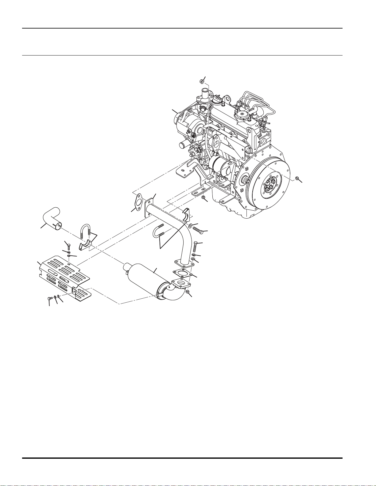
1
2 1 • Gasket, Exhaust
3 1 • Gasket, Muffler
41•Muffler
5 001990072 2 U-Clamp, M8-1.25 x 38 mm
6 4378129 1 Head, Pipe
7 4387057 1 Cover, Exhaust
8 450168 2 Screw, M6-1 x 12 mm Hex Head
9 450171 2 Screw, M6-1 x 16 mm Hex Head
10 450216 2 Screw, M10-1.5 x 35 mm Hex Head
11 450389 4 Washer, M6 x 12.5 x 1.8
12 450390 4 Washer, M8 x 17 x 1.8
13 450391 2 Washer, M10 x 21 x 2.2
14 450410 4 Lockwasher, M6 x 9.6 x 1.5
15 450411 4 Lockwasher, M8 x 12.75 x 2
16 450194 4 Screw, M8-1.25 x 35 mm Hex Head
17 001339050 8 Nut, M8-1.25 Hex Staytite
18 450454 2 Nut, M10-1.5 Hex Flange
19 4378128 1 Tailpipe
4399316 1 Engine, Kubota D1105-E4B
> Change from previous revision
35
Page 50

TR320
A
B
A
B
1
2
10
4
5
5
5
6
7
8
9
42
11
12
12
13
13
14
14
15
16
17
18
19
20
21
22
23
24
25
26
27
27
28
28
29
30
30
31
31
31
31
31
31
31
31
31
32
33
34
35
41
41
36
37
38
39
40
S≤ 15 mg/kg
4324674
18
17.1 Fuel Tank and Routing
Serial No. All
36
Page 51

TR320
Item Part No. Qty. Description Serial Numbers/Notes
1
2 4387306 1 Vent Tube
3 4354952 1 Tank, Diesel Fuel
4 4287174 1 • Cap, Fuel Tank
5 672550 3 • Grommet
6 4291031 1 • Fitting, 1/4 Straight Barb
7 4382366 1 • Gauge, Fuel Level
8 4379146 1 • Tube, Fuel Pick Up 80 Mesh Screen On End
9 4386486 1 • Tube, Fuel Return Line
10 4379626 1 • Tank, Diesel Fuel
11 450214 2 Screw, M10-1.5 x 25 mm Hex Head
12 450389 3 Washer, M6 x 12.5 x 1.8
13 450391 3 Washer, M10 x 21 x 2.2
14 450410 3 Lockwasher, M6 x 9.6 x 1.5
15 450412 2 Lockwasher, M10 x 15.9 x 2.5
16 672728 1 Hose, Fuel Breather
17 450543 1 Screw, M6-1 x 25 mm Pan Head
18 469016509 2 P-Clip
19 4247950 1 Clip, Fuel Hose
20 452000327 1 Washer, 1/4 x 3/4 x .064
21 4384346 1 Strap, Fuel Tank See 2.1 for mounting
22 672789 1 Hose, Fuel Pump to Fuel Filter Cut Length 620 mm
23 672788 1 Hose, Tank to Pre-Filter Cut Length 900 mm
24 672790 1 Hose, Pre-Filter to Fuel Pump Cut Length 110 mm
25 672787 1 Hose, Fuel Filter to Engine Cut Length 665 mm
26 450172 1 Screw, M6-1 x 25 mm Hex Head
27 450390 3 Washer, M8 x 17 x 1.8
28 450411 3 Lockwasher, M8 x 12.75 x 2
29 452435 1 Nut, M6-1 Flange Nyloc
30 452436 3 Nut, M8-1.25 Flange Nyloc
31 4283232 10 Clamp, Hose (9.5-12 mm)
32 450194 2 Screw, M8-1.25 x 35 mm Hex Head
33 450192 1 Screw, M8-1.25 x 25 mm Hex Head
34 450454 1 Nut, M10-1.5 Hex Flange
35 4344103 1 P-Clip, 48 mm Rubber Sleeve
36 450213 1 Screw, M10-1.5 x 20 mm Hex Head
37 1 Fuel Pre-Filter
38 1 Fuel Pump REFERENCE M2, See 46.1
39 1 Fuel Filter
40 672715 1 Cut Length 1370 mm
41 4324674 1
42 450170 2
002497040 1 Breather
5001182
5001948
5001189
2500809
• Cartridge, Fuel Filter
1
Hose, Engine Return to Tank
Decal, Fuel
Screw, M6-1 x 16 mm Hex Head
> Change from previous revision
37
Page 52

TR320
23
2
2
2
3
3
3
3
4
4
4
4
4
5
5
6
7
8
9
10
11
12
14
15
15
15
16
16
17
17
18
19
20
25
26
21
22
22
24
TR320
B
I
O
D
E
G
R
A
D
A
B
L
E
F
L
U
I
D
21
13
15
1
2
15
17
27
28
18.1 Hydraulic Tank and Hood
Serial No. All
38
Page 53

TR320
Item Part No. Qty. Description Serial Numbers/Notes
1
2 450214 9 Screw, M10-1.5 x 25 mm Hex Head
3 450412 9 Lockwasher, M10 x 15.9 x 2.5
4 001599264 10 Washer, 25/64 x 1 x .106
5 4312406 2 Hinge, Dies Cast Zinc
6 4363146 1 Bracket, Hood Mount
7 4354951 1 Tank, Hydraulic
8 4370752 1 • Breather, Filter
9 4394849 1 • Strainer, Suction
10 671857 1 Lanyard, Hood
11 669840 4 Pop Rivet, 4.8 x 14
12 2198112 1 Draw Latch
13 N/S 1 • Latch, Keeper
14 4356728 1 Hood, Engine
15 450387 14 Washer, M4 x 9 x 0.9
16 450520 4 Screw, M4-0.7 x 20 mm Pan Head
17 452717 10 Nut, M4-0.7 Hex Nyloc
18 MBG6720 1 Bracket, Hood Latch
19 4334427 4 Screw, M6-1 x 20 mm Button Head
20 450452 4 Nut, M6-1 Hex Flange
21 4111408 1 Decal, Bio-Fluid
22 4164860 1 Decal, Hydraulic Fluid
23 450454 1 Nut, M10-1.5 Hex Flange
24 450477 1 Screw, M10-1.5 x 20 mm Hex Flange
25 4397106 2 Decal, Jacobsen
26 4399347 2 Decal, TR320
27 4389850 1 Cargo Net, Hood
28 450519 6 Screw, M4-0.7 x 16 mm Pan Head
450620 4 Screw, M6-1 x 20 mm Countersunk
339904 1 • • O-Ring, -32 ORB
> Change from previous revision
39
Page 54

TR320
1
2
3
3
3
4
5
6
7
8
9
10
11
12
13
14
15
21
22
16
17
19
20
3
18
18
19.1 Hydraulic Valve Assembly
Serial No. All
40
Page 55

TR320
Item Part No. Qty. Description Serial Numbers/Notes
1
2 450170 2 Screw, M6-1 x 16 mm Hex Head
3 450389 15 Washer, M6 x 12.5 x 1.8
4 4395287 1 Filter, Charge
5 450412 4 Lockwasher, M10 x 15.9 x 2.5
6 452000326 4 Washer, 3/8 x 3/4 x .072
7 456110066 4 Screw, 3/8-16 x 1” Hex Head
8 2811364 1 Steering Wheel
9 2811365 1 • Cap, Steering Wheel
10 4198282 1 Steering Column
11 450020338 1 • Nut, 5/8-18 Thin Hex
12 4375586 1 • Bellows
13 4375587 1 • Cover, Foot Pedal
14 450377 2 Nut, M6-1 Hex Nyloc
15 4393849 1 Valve, Steering See 42.1 for Service Parts
16 4394670 1 Manifold, Drain Header
17 4394753 1 Bracket, Drain Manifold
18 450737 4 Screw, M10-1.5 x 20 mm
1
9 450172 2 Screw, M6-1 x 25 mm Hex Head
20 452435 2 Nut, M6-1 Flange Nyloc
21 450712 4 Screw, M6-1 x 20
2
2 450410 4 Lockwasher, M6 x 9.6 x 1.
4201021 1 Valve, Brake See 35.1 for Service Parts
2811255 1 • Cartridge, Filter Element
4395269 1 • Filter Head with Indicator
4395531 1 • • Indicator, Filter Service
4278451 1 • Kit, Gas Spring Pivot
4399466 1 • Kit, Steering Column Pivot
4397006 1 • Kit, Steering Column Pivot
4270219 1 • Kit, Universal Joint Service
4280351 1 • Gas Spring
SHCS
mm SHCS
5
> Change from previous revision
41
Page 56
TR320
14
14
Port L
Port R
Drain Tube
(Port 1)
Brake Tube
(Port X)
Port B
Port A
Rear Wheel
Motor Ports
6
6
6
11
13
12
6
1
2
3
16
4
10
10
9
8
7
7
5
2
15
15
20.1 3WD Traction Hydraulics
Serial No. All
42
Page 57

TR320
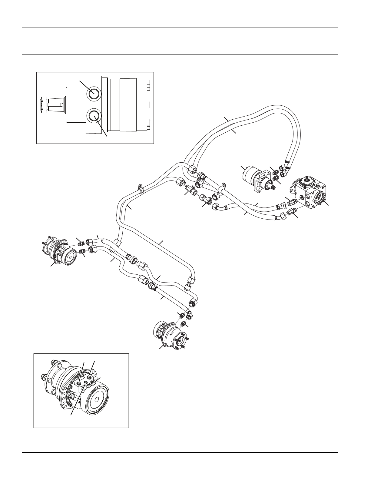
Item Part No. Qty. Description Serial Numbers/Notes
1
2 340036 2 Fitting, -12 ORFS x -12 ORB 45°
3 4391257 1 Hose, Transmission Pressure Line Traction Pump Port B
4 4391006 1 Tube, Transmission Pressure Line
5 4390473 1 Tube, Front Motor Return Line
6 339989 4 Fitting, -10 ORFS x -10 ORB Straight
7 4379926 2 Wheel Motor, 235 cc See 8.1
8 4391026 1 Tube, Front Motor Transmission Line Left Motor Port L
9 4398266 1 Tube, Transmission Line Front Motors Right Motor Port L
10 340122 2 Fitting, -12 ORB Swivel Run Tee
11 4398746 1 Hose, Rear Motor Pressure Rear Motor Port A
12 4379887 1
13 4398747 1 Hose, Rear Motor Return Rear Motor Port B
14 339993 2 Fitting, -12 ORFS x -10 OR
15 4391566 2 Hose, Front Motor Transmission Line
16 4391258 1 Hose, Transmission Return Line Traction Pump Port A
4203740 1 Pump, LPV 35 cc Piston
339912 1 • O-Ring, -12 ORFS
339900 1 • O-Ring, -12 ORB
339911 1 • O-Ring, -10 ORFS
339899 1 • O-Ring, -10 ORB
339912 2 • O-Ring, -12 ORFS
3
Motor, 28.7 in
33
9912 1 • O-Ring, -1
9899 1 • O-Ring, -1
33
Wheel
2 ORFS
0 ORB
B
> Change from previous revision
43
Page 58

TR320
R
L
P
T
E
Hose (20)
To Lift Valve Port P
Hose (15)
From Pump
Hose (21)
To Lift Valve Port T
Steering Valve viewed from end
Hose (18)
To Steering Cylinder
Hose (17)
To Steering Cylinder
Front and Rear Reel Valve
Viewed From Rear
TP
2
1
3
4
5
6
17
7
15
16
15
8
14
9
10
11
12
13
21.1 3WD Gear Pump and Steering Hydraulics
Serial No. All
44
Page 59

TR320
Item Part No. Qty. Description Serial Numbers/Notes
1
2
3
4
5 339999 1 Fitting, 90° 16-16 Straight Thread
6 340030 1 Fitting, 45° 8-10 Straight Thread
7 4371126 1 Hose, Pump to Steeri
8 4391206 1 • Hose, Steering Valve to Cylinder Valve Port L, Cylinder Left Port
9 4391206 1 • Hose, Cylinder to Steering Valve Cylinder Right Port, Valve Port R
10 4399268 1 Tube, Pressure Line - Lift Valve
11 4399271 1 Tube, Return Line - Steering Valve
12 340062 1 Fitting, 90° 6-8 Straight Thread
13 4169021 1 Weight Transfer And Lift Valve
14 4393849 1 Valve, Steering
15 339972 2 Fitting, -4 ORFS x -4 ORB Straight
16 4244289 1 Steering Cylinder See 39.1 for Service Parts
4354951 1 Tank, Hydraulic
4394849 1 • Strainer, Suction
339
904 1 • • O-Ring, -3
340001 1 Fitting, -20 ORFS x -2
339
914 1 • O-Ring, -2
902 1 • O-Ring, -2
339
4391256 1 Hose, Tank Suction Line
4396209 1 Bundle, 3WD Steering Hose
339908 1 • O-Ring, -4 ORFS
339896 1 • O-Ring, -4 ORB
2 ORB
0 ORB
0 ORFS
0 ORB
ng Valve
Steering Valve Port P
> Change from previous revision
45
Page 60

TR320
1
3
4
5
6
7
11
8
9
10
10
10
10
1
1
2
10
10
22.1 Front And Rear Reel Hydraulics
Serial No. All
46
Page 61

TR320
Item Part No. Qty. Description Serial Numbers/Notes
1
2 4355571 1 Valve, Reel See 36.1
3 4391087 1 Hose, Pressure Line Rear Unit
4 4391086 1 Hose, Pressure Line Front RH Unit
5 4391088 1 Hose, Return Line Rear Unit
6 4399579 1 Tube, Return Line Cutter Unit
7 4399578 1 Tube, Pressure Line Cutter Unit
8 339985 1 Fitting, -8 ORFS x -10 ORB Straight
9
10 340067 6 Fitting, -8 ORFS x -10 ORB 90°
1
1 4391084 1 Hose, Pressure Line Front LH Unit
4140034 3 Motor, Reel See 24.1
339910 1 • O-Ring, -8
33
9899 1 • O-Ring, -1
340070 1 Fitting, 10-10 Straight Thread 90°
339910 1 • O-Ring, -8
33
9899 1 • O-Ring, -1
ORFS
0 ORB
ORFS
0 ORB
> Change from previous revision
47
Page 62

TR320
5
6
7
8
5
5
5
10
3
4
1
9
9
2
Lift Valve
Viewed From Front
CR
L
A
B
2
23.1 Front And Rear Lift Hydraulics
Serial No. All
48
Page 63

TR320
Item Part No. Qty. Description Serial Numbers/Notes
1
2 669395 2 Cylinder, Lift See 40.1 for Service Parts
3 4390979 1 Hose, Lift Arm Front LH
4 4399747 1 Hose, LIft Arm Front RH
5 340061 5 Fitting, -6 ORFS x -6 ORB 90°
6
7 4391047 1 Hose, Lift Ar
8 670815 1 Cylinder, Lift Rear
9 4287311 3 Disk, Orifice (0.029 Dia)
10 337317 1 Fitting, One Way Orif
4169021 1 Weight Transfer And Lift Valve See 37.1 for Service Parts
339909 1 • O-Ring, -6
33
9897 1 • O-Ring, -6
4186000 1 Fitting, 11/16 ORS
ORFS
ORB
m
Rear Unit
ice
> Change from previous revision
49
Page 64

TR320
1
21
22
8
6
1
1
6
T
4
Lift Valve Viewed From Rear
Port L
Port R
Drain Tube
(Port 1)
Brake Tube
(Port X)
Brake Valve
Viewed From Bottom
CHG
DR
PB1
CHG
DR
PB1
23
23
26
2
3
4
17
20
18
16
24
5
3
7
19
10
11
12
13
14
9
15
20
13
25
5
5
24.1 Drain Hydraulics
Serial No. All
50
Page 65

TR320
Item Part No. Qty. Description Serial Numbers/Notes
1
2 4201021 1 Valve, Brake See 35.1 for Service Parts
3 4379926 2 Wheel Motor, 235cc See 8.1
4 4169021 1 Weight Transfer And Lift Valve See 37.1 for Service Parts
5 339977 3 Fitting, -6 ORFS x -4 ORB Straight
6
7 4391082 1 Hose, Drain Line Front RH Unit
8 4383826 1 Tube, Manifold to Tank
9 4287314 1 Disk, Orifice (0.070 Dia)
10 4390644 1 Tube, Front Motor Drain Feeder Line
11 4390643 1 Tube, Front Motor Drain Line
12 4399271 1 Tube, Return Line - Steering Valve
13 339980 2 Fitting, -6 ORFS x -8 ORB Straight
4 340097 1 Fitting, M-Tee
1
15 4399269 1 Tube, Bypass Line Lift Valve
16 340067 1 Fitting, -8 ORFS x -10 ORB 90°
17
18 4391080 1 Hose, Drain Line Rear Unit
19 4391081 1 Hose, Drain Line Front LH Unit
20 340061 2 Fitting, -6 ORFS x -6 ORB 90
1 339984 1 Fitting, -8 ORFS x -8 ORB Straight
2
2
2 339980 1 Fitting, -6 ORFS x -8 ORB Straight
2
3 339979 3 Fitting, -6 ORFS x -6 ORB Straight
24
25 4394670 1 Header Manifold
26 4398306 1 Tube, Return Line Lift Valve
4140034 3 Motor, Reel
339909 1 • O-Ring, -6 ORFS
339896 1 • O-Ring, -4
340263 1 Fitting, 6-6 Straight Thread
339909 1 • O-Ring, -6
33
9898 1 • O-Ring, -8
339910 1 • O-Ring, -8
33
9899 1 • O-Ring, -1
4390640 1 Tube, Brake Valve Drain Line
33
9909 1 • O-Ring, -6
9897 1 • O-Ring, -6
33
339910 1 • O-Ring, -8
9898 1 • O-Ring, -8
33
339909 1 • O-Ring, -6
9898 1 • O-Ring, -8
33
339909 1 • O-Ring, -6
33
9897 1 • O-Ring, -6
4354951 1 Tank,
Hydraulic Se
ORB
ORFS
ORB
ORFS
0 ORB
ORFS
ORB
ORFS
ORB
ORFS
ORB
ORFS
ORB
°
e 18.1
> Change from previous revision
51
Page 66
TR320
8
8
Reel Valve Viewed From Rear
TP
Brake Valve
Viewed From Bottom
Brake Valve
Viewed From Left
CHG
DR
PB1
PB2
7
7
1
3
7
2
5
6
19
19
4
9
10
11
13
15
16
14
14
12
18
A
Reel Valve Viewed From Front
B
G
17
25.1 Brake Valve and Charge Hydraulics
Serial No. All
52
Page 67

TR320
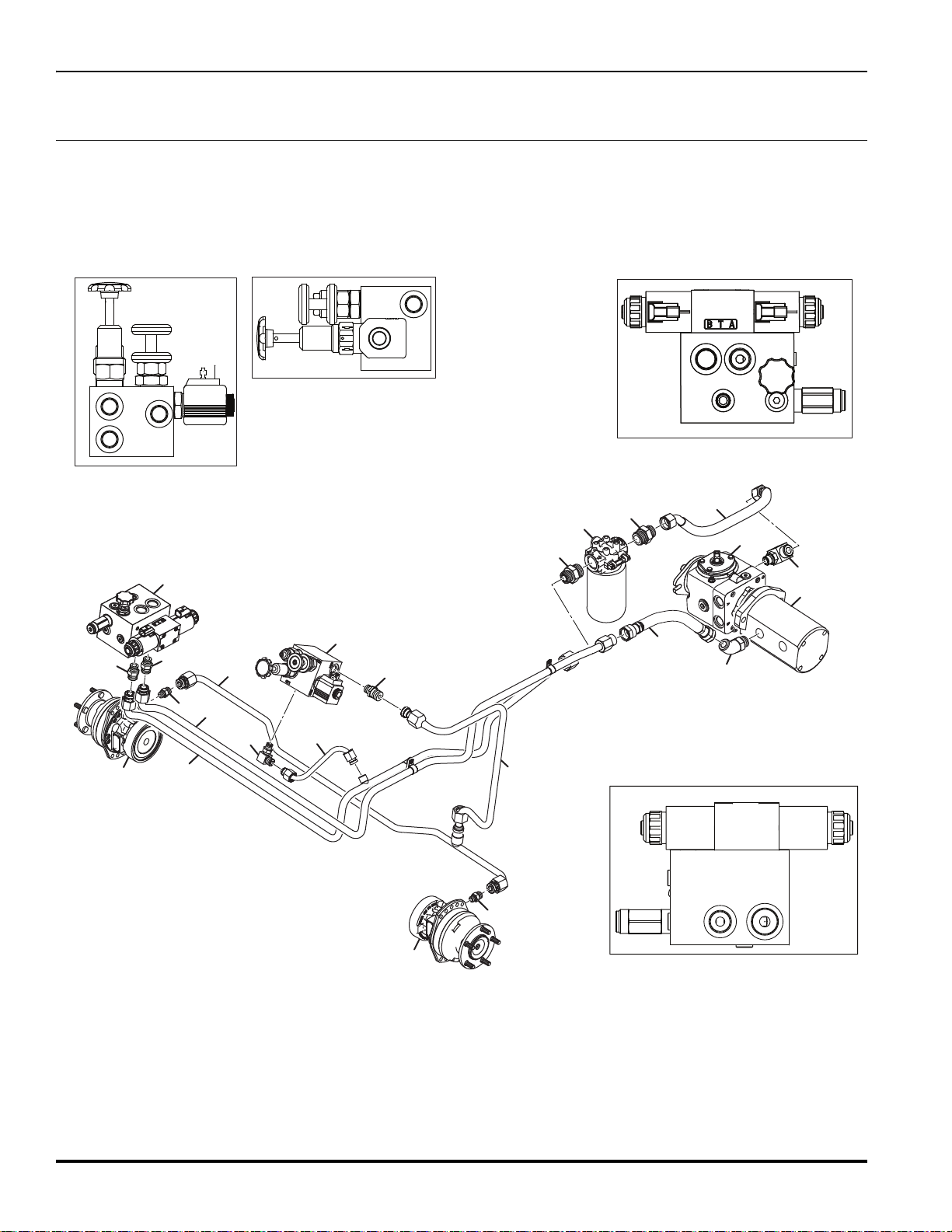
Item Part No. Qty. Description Serial Numbers/Notes
1
2 4201021 1 Valve, Brake See 35.1 for Service Parts
3 4391338 1 Tube, Brake Line LH Front Motor
4 4390638 1 Tube, Brake Pressure Line
5 4390635 1 Tube, Cutter Valve Pressure Line
6 4390462 1 Hose, Cutter Valve to Filter
7 339979 3 Fitting, -6 ORFS x -6 ORB Straight
8 4379926 2 Wheel Motor, 235 cc See 8.1
9 4134071 1 Pump, Cutter And Steering
10 4203740 1 Pump, LPV 35 cc Piston
11 4398146 1 Hose, Return Line - Charge Filter
12 340074 1 Fitting, -12 ORFS x -10 OR
13 4395287 1 Filter, Charge
14 339996 2 Fitting, -12 ORFS x -16 OR
15 4391266 1 Hose, Cutter Valve Pressure Line
16 340033 1 Fitting, 45 Deg 10-10 Straight Thread
17 4390639 1 Tube, Brake Valve to Charge Filter
18 340061 1 Fitting, -6 ORFS x -6 ORB 90
1
9 339989 2 Fitting, -10 ORFS x -10 ORB Straight
4355571 1 Valve, Reel See 36.1 for Service Parts
339909 1 • O-Ring, -6
33
9897 1 • O-Ring, -6 ORB
33
9912 1 • O-Ring, -12 ORFS
339900 1 • O-Ring, -12 ORB
2811255 1 • Cartridge, Filter Element
4395269 1 • Filter Head with Indicator
4395531 1 • • Indicator, Filter Service
33
9912 1 • O-Ring, -12 ORFS
339901 1 • O-Ring, -16 ORB
9909 1 • O-Ring, -6
33
9897 1 • O-Ring, -6
33
339911 1 • O-Ring, -1
33
9899 1 • O-Ring, -1
ORFS
B
B
°
ORFS
ORB
0 ORFS
0 ORB
> Change from previous revision
53
Page 68
TR320
7
5
4
14
3
2
6
1
26.1 Oil Cooler Hydraulics
Serial No. All
54
Page 69

TR320
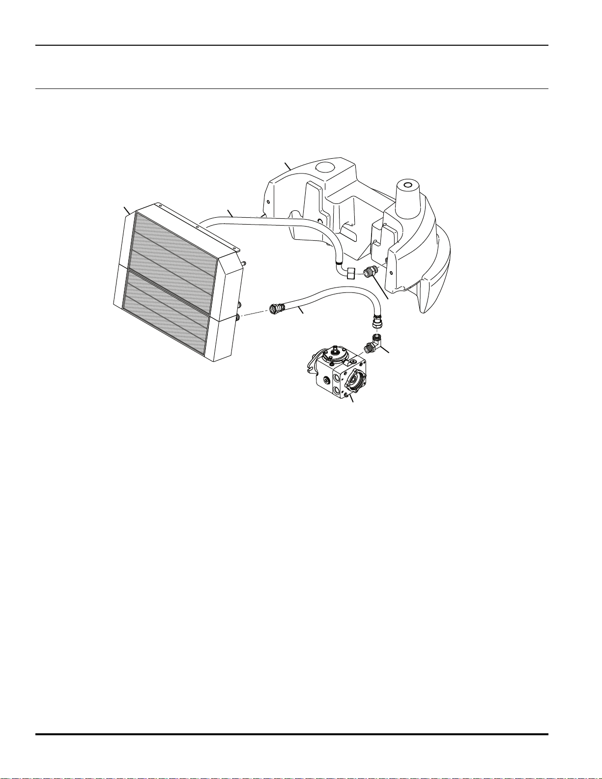
Item Part No. Qty. Description Serial Numbers/Notes
1
2 4391186 1 Hose, Cooler Return Line
3 4391546 1 Hose, Cooler inlet Line
4 339994 1 Fitting, 12 - 12 Straight Thread
5 340074 1 Fitting, -12 ORFS x -12 ORB 90°
6
7
4354951 1 Tank, Hydraulic See 18.1
339912 1 • O-Ring, -1
33
9900 1 • O-Ring, -1
4376688 1 Radiator
4203740 1 Pump, LPV 35 cc
2 ORFS
2 ORB
and Hydraulic Oil Cooler
Piston Se
e 44.1 for Service Parts
> Change from previous revision
55
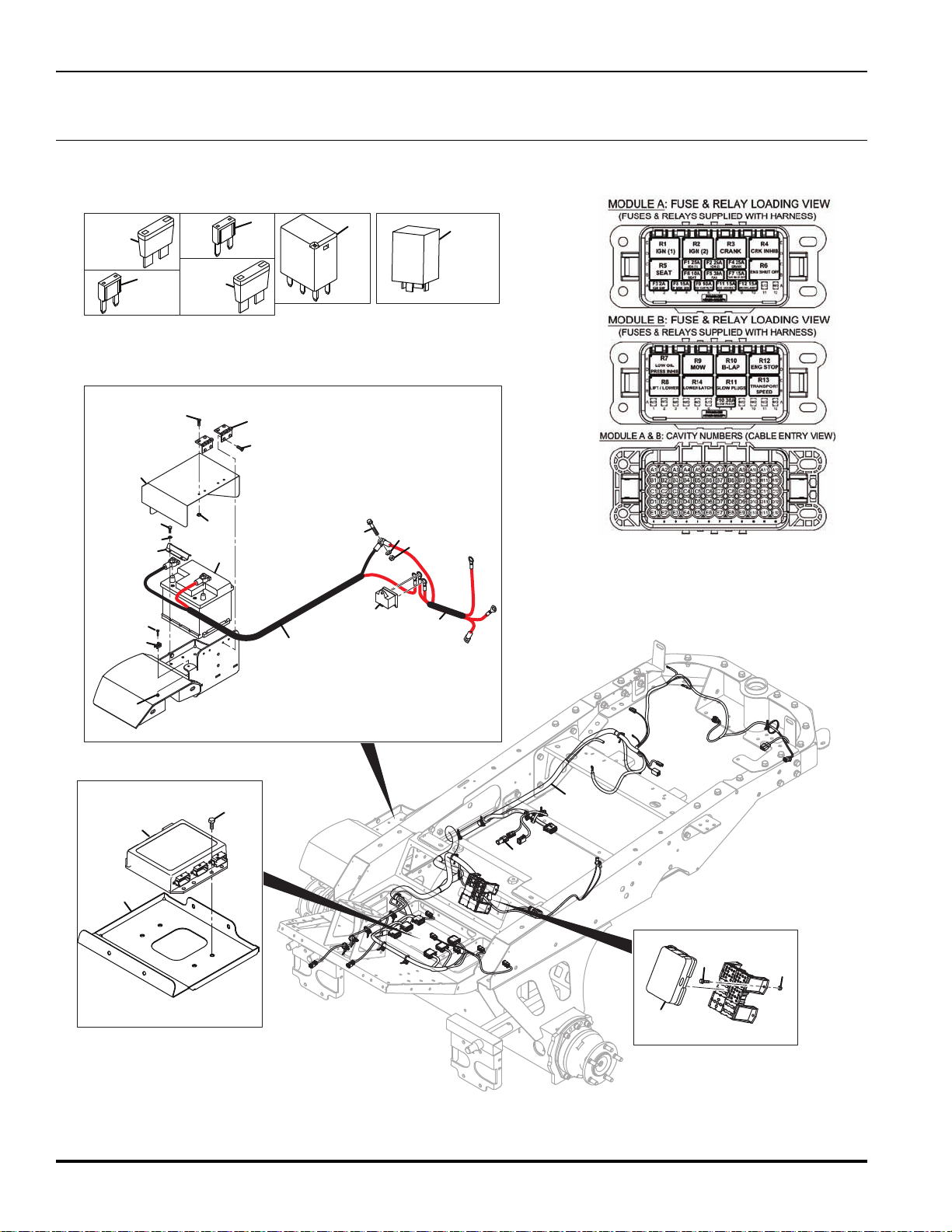
Page 70
TR320
K1
F10
K3
15 20
F7
F4
K4
20 10
F8
F6
30
F5
K2
30
F3
40
F2
30
F9
K1-K14
F1, F2, F4
25
8
15
F7, F8, F11, F12
5
10
F6, F9
4
6
F5, F10
30
7
1
1
2
12
15
16
17
18
19
20
21
22
24
25
26
27
28
29
30
31
32
33
13
14
34
23
34, 35
27.1 Electrical
Serial No. All
56
Page 71

TR320
Item Part No. Qty. Description Serial Numbers/Notes
1
2 4394946 1 Harness, MAR Standard
3 1 • Fuse, 2 Amp REFERENCE F3, See 46.1
4 4312213 2 • Fuse, 10 Amp Mini REFERENCE F6, F9, See 46.1
5 4312246 4 • Fuse, 15 Amp Mini
6 4312217 3 • Fuse, 25 Amp Mini REFERENCE F1, F2, F4, See 46.1
7 4312216 2 • Fuse, 30 Am
8
9 670576 1 Positive Battery Terminal Not Shown
10 670577 1 250A Fuse Battery Terminal Not Shown
11 670578 1 Positive Battery Terminal Cover Not Shown
12 670579 1 Negative Battery Terminal Not Shown
13 450389 2 Washer, M6 x 12.5 x 1.8
14 450528 1 Screw, M5-0.8 x 16 mm Pan Head
15 450190 4 Screw, M8-1.25 x 16 mm Hex Head
16 4395081 1 Bracket, Controller Mount
17 452686 4 Screw, M5-0.8 x 16 mm Taptite
18 4316092 1 Cover, 2 x 3 Dill Blox
19 N/S 1 Battery, 12V, 45Ah, 425 Amp REFERENCE B1, See 46.1
20 4391935 1 Mower Control Unit (MCU) REFERENCE U1, See 46.1
21 669881 1 Harness, Ground Starter Alternator
22 4394947 1 Harness, Battery Cable
23 450619 8 Screw, M6-1 x 16 mm CSK
24 450379 1 Nut, M10-1.5 Hex Nyloc
25 450391 1 Washer, M10 x 21 x 2.2
26 452402 1 Screw, M10-1.5 x 50 mm Hex Flange
27 4309904 1 3 Way Distribution Block See 6.1
28 4321434 2 Hinge, Seat Plate
29 4395489 1 Saddle Clip, Cable Tie Mount
30 4395726 1 Clamp, Battery
31 4396746 1 Lid, Battery Box
32 450170 2 Screw, M6-1 x 16 mm Hex Head
33 450323 4 Nut, M6-1 Hex
34 672638 1 Seat Delay Module
35 672639 1 Lift Delay Module
450376 5 Nut, M5-0.8 Nyloc
4329751
14 • Relay, 12V, 35A, 280 Micro REFERENCE K1-K14 See 46.1
REFERENCE F7, F8, F11, F12
See 46.1
p REFER
ENCE F5, F10 See 46.1
> Change from previous revision
57
Page 72

TR320
15
13
2
9
11
5
17
33
35
43
38
27
28
8
9
1
14
21
19
16
26
4
12
21
22
46
6
24
29
24
7
10
42
38
41
34
36
41
40
38
39
40
43
38
41
34
42
39
38
31
32
44
3
37
30
25
18
23
18
A
A
14
20
20
B
B
37
22
20
45
28.1 Mounting And Lift Arms
Serial No. All
58
Page 73

TR320
Item Part No. Qty. Description Serial Numbers/Notes
1
2 4386846 1 Lift Reel Unit Center
3 670815 1 Hydraulic Cylinder, 32 x 50 mm
4 669395 2 Hydraulic Cylinder, 32 x 137 mm
5 4389447 1 Pivot Pin
6 4387048 2 Pivot Pin
7 4395244 1 Pivot Pin, 19.05 x 135 mm
8 4396808 1 Clamp, Center Unit Bracket
9 4399631 2 End Cap, 60 x 60 x 4
10 452055 1 Circular Clip Extension, 30 x 1.5 T
11 452437 1 Nut, M10 Flange Nyloc
12 4313086 3 Washer, 6.5 x 10.8 x 1.8
13 4370167 10 Cable Tie Mount
14 4371171 3 Pin Lift Ram
15 4394966 2 Pivot Pin, 19.09 x 135 mm
16 450170 3 Screw, M6-1 x 16 mm Hex Head
17 450217 1 Screw, M10 x 40 mm Hex Head
18 450386 4 Washer, M3 x 7 x 0.6
19 450391 1 Washer, M10 x 21 x 2.2
20 450392 6 Washer, M12 x 24 x 2.7
21 450412 3 Lockwasher, M10 x 15.9 x 2.5
22 451241 6 Slit Pin, 3.2 x 22 mm
23 452716 2 Nut, M3-0.5 Hex Nyloc
24 62464-4A 4 Thrust Washer, 1.25 x 1.937 x 0.03
25 450511 2 Screw, M3-0.5 x 25 mm Pan Head
26 450213 2 Screw, M10-1.5 x 20 mm Pan Head
27 450079 2 Bolt, M16 - 2 x110
28 450393 2 Washer, M16 x 30 x 3.3
29 452439 2 Nut, M16 Flange Nyloc
30 4125831 1 Proximity Switch
31 4397248 1 Lift Arm, Reel Front RH, For 26” US and UK Reels
32 4397254 1 Lift Arm, Reel Front LH, For 26” US and UK Reels
33 4386866 1 Lift Arm, Reel Center, For 26” US and UK Reels
34 4117977 3 Pivot Shaft For 26” US and UK Reels
35 4130255 2 Bushing For 26” US and UK Reels
36 4164280 1 Collar For 26” US and UK Reels
37 4252550 2 Bushing, 1/2 x 5/8 x 1/2” Flange For 26” US and UK Reels
38 450412 15 Lockwasher, M10 x 15.9 x 2.5 For 26” US and UK Reels
39 450729 3 Screw, M8-1.25 x 50 Hex Head For 26” US and UK Reels
40 MBG4592 3 Collar For 26” US and UK Reels
41 MBG4653 9 Collar For 26” US and UK Reels
42 4397986 3 Clamp Plate For 26” US and UKReels
43 450739 12 Screw, M10-1.5 x 30 Hex Head For 26” US and UK Reels
44 002993013 3 Lubricator, M6 For 26”US and UK Reels
45 670963 2 End Cap, 60 x 40 x 4 (Shallow Type)
46 4245590 2 AV Washer, 10.7 x 16.6 x 2.5
4386760 1 Lift Arm Mounting
4386826 1 • Bushing, Pin
4386826 1 • Bushing, Pin
> Change from previous revision
59
Page 74

TR320
3
4
1
2
2
8
23
30” Reel
Center Pivot Arm Weldment
4
5
7
11
10
8
6
9
12
21
20
13
16
17
21
19
14
31
15
18
22
26” and 30” Reel Left Pivot Arm Weldment
26
25
27
30
35
28
8
23
1
24
26” Reel
Center Pivot Arm Weldment
29
33
34
33
32
29.1 Pivot Arms
Left and Center Reel Shown, Right Opposite.
Serial No. 671567 - All
Serial No. 671568 - All
Serial No. 671569 - All
Serial No. 673530 - All
Serial No. 673531 - All
Serial No. 673532 - All
60
Page 75

TR320
Item Part No. Qty. Description Serial Numbers/Notes
1
1 4396986 1 30” Center Pivot Arm
2 002193318 2 • Bushing
3 4396889 1 26” Left Pivot Arm For 26” US and UK Reels
3 4396890 1 26” Right Pivot Arm For 26” US and UK Reels
3 4399255 1 30” Left Pivot Arm
3 4399254 1 30” Right Pivot Arm
4 002193318 2 • Bushing
5 4397966 1 Pivot Bracket, Left Side For 26” US Reels
5 4139281 1 Pivot Bracket, Left Side For 26” UK Reels
6 4397967 1 Pivot Bracket, RIght Side For 26” US Reels
6 4139349 1 Pivot Bracket, RIght Side For 26” UK Reels
7 001399032 2 Nut, 1/2-20 Nyloc For 26” US and UK Reels
8 001599052 12 Flat Washer
9 400260 12 Screw, 3/8-16 x .875 Hex Head
10 4131749 3 Motor, Reel
11 4139374 2 Spacer, Pivot For 26” US and UK Reels
12 4151277 2 Bumper, Lift Arm For 30” US Center Reel
13 4399247 1 Roller, Reel Unit For 26” US and UK Reels
14 4399270 1 Bracket, Reel Unit For 26” US and UK Reels
15 446142 12 Lockwasher, 3/8 Heavy
16 450059 2 Screw, M12-1.75 x 100 mm Hex Head
17 450392 1 Washer, M12 x 24 x 2.7 For 26” US and UK Reels
18 450433 2 Lockwasher, M8 x 15 x 0.8 For 26” US and UK Reels
19 450725 2 Screw, M8-1.25 x 30mm Socket Head For 26” US and UK Reels
20 450866 4 Screw, M8-1.25 x 25mm Socket Head For 26” US and UK Reels
21 452436 6 Nut, M8-1.25 Flange Nyloc For 26” US and UK Reels
22 452438 1 Nut, M12-1.75 Flange Nyloc For 26” US and UK Reels
23 456010577 2 Screw, 1/2-20 x 1 1/2” Hex Head For 26” US and UK Reels
24 4397726 2 Bumper, Lift Arm For 26” US and UK Center Reels
25 4397846 1 Pivot Bracket, Left Side For 26” US Center Reel
26 4397847 1 Pivot Bracket, RIght Side For 26” US Center Reel
27 450400 6 Washer, M8 x 21 x 1.8 For 26” US and UK Center Reel
28 450015 2 Screw, M8-1.25 x 35 mm Hex Head For 26” US and UK Center Reel
29 REF 3 Fitting, -6 ORFS x -4 ORB Straight See 24.1
30 REF 6 Fitting, -8 ORFS x -10 ORB See 22.1
31 450214 1 Screw, M10-1.5 x 25 mm Hex Head For 26” UK Reels
32 450379 1 Nut, M10-1.5 Hex Nyloc For 26” UK Reels
33 450391 2 Washer, M10 x 21 x 2.
34 4344103 1 P-Clip, 48 mm Rubber Slee
35 MBF0895A.07 1 Assembly, 26” x 7K Cylinder, Left Side For 26” UK Reels
35 MBF0325B.07 1
35 MBF0895A.07 1 Assembly, 26” x 7K Cylinder, Left Side For 26” UK Reels
4396888 1 26” Center Pivot Arm For 26” US and UK Reels
2
ve
Assembly, 26” x 7K Cylinder, Right Side
For 26” UK Reels
For 26” UK Reels
For 26” UK Reels
> Change from previous revision
61
Page 76

TR320
5 Blade Reel (Optional)
7 Blade Reel (Standard)
10 Blade Reel (Optional)
26 in. (660 mm) Reels30 in. (762 mm) Reels
67114 67116 67115 67123 67125 67124
2500712
5002087
2500714
Left Center Right Left Center Right
2500712
5002087
2500714
2500713
5002088
2500715
503359
5002089
503361
503359
5002089
503361
503360
5002090
503362
Number of
Reel Blades
1
2
3
4
5
6
7
9
10
11
11
12
12
13
13
14
14
15
15
16
16
17
17
18
19
20
21
22
23
24
25
26
27
28
29
30
31
33
33
34
34
35
35
37
38
8
39
36
40
18
31
32
41
42
7 US Blade Reel (Standard)
26 in. (660 mm) Reels
1001748
10017481001748
Left Center Right
Number of
Reel Blades
5 UK Blade Reel (Standard)
11UK Blade Reel (Standard)
7 UK Blade Reel (Standard)
26 in. (660 mm) Reels
MBF0895A.07 MBF0895A.07
MBF0325B.07
-
Left Center Right
- -
Number of
Reel Blades
32
30.1 Inner Reel Assembly
Left and Center Reel Shown, Right Opposite.
Serial No. 671567
Serial No. 671568
Serial No. 671569
Serial No. 673530
Serial No. 673531
Serial No. 673532
62
Page 77

TR320
Item Part No. Qty. Description Serial Numbers/Notes
1
1 1001642 1 30” Reel Mower Frame
2 1001458 1 Bearing Housing, Reel Motor
3 3001152 1 • Washer
4 3000983 1 • Oil Seal
5 400555 1 • Grease Fitting
6 313456 1 • Bearing, Cu
7
8 3003086 2 • Stud, 3/8-16 x 5/8”
9 364148 1 Spring, Compression
10 458039 1 Snap Ring
11 3003517 2 Shoulder Bolt, 3/4-16 Special
12 306828 2 Washer
13 3004370 2 Locknut, 3/4-16 Thin Security
14 434031 2 Screw, 1/4-20 x 3/4” Hex Socket Head
15 400446 2 Screw, 1/2-20 x 2” Hex Head
16 3003389 2 Bushing, Housing Pivot
17 364151 2 Washer, Wave
18 445789 2 Nut, 1/2-20 Spiralock Flange
19 340796 1 Coupler, Motor
20 1001464 1 Bearing Housing
21 3001152 1 • Washer
22 3000983 1 • Oil Seal
23 313456 1 • Bearing, Cup
24 471214 1 • Grease Fitting
25 471242 1 • Relief Fitting, 1/8 NPTF Grease
26 See Chart 1 Reel 2500712
27 364283 1 Spacer, Tube 2500713
28 364259 1 Washer, Bearing Retainer 2500714
29 400264 1 Screw, 3/8-16 x 1-1/4” Hex Head 2500715
30 446142 1 Lockwasher, 3/8 Heavy 5002087
31 3003611 2 Nut, Reel Adjuster 5002088
32 472519 2 Plug 5002089
33 365995 2 Washer, Spherical 5002090
34 445718 2 Locknut, 5/8-18 Hex Stover 503359
35 3004189 2 Screw, Reel Adjuster 503360
36 364777 1 Gasket, Solid 503361
37 443110 2 Nut, 3/8-16 Hex 503362
38 446142 2 Lock washer, 3/8 Heavy
39 453011 2 Flat washer, 3/8
40 3000900 2 Cover. Bearing Housing
41 314722 2 Plate, Serial Number
42 409508 2 Screw, #2 x 1/4” Round Head
1001643 1 26” Reel Mower Frame
p
471242 1 • Relief Fitting, 1/8 NPTF Grease
> Change from previous revision
63
Page 78

TR320
1
2
2
3
3
3
4
5
6
7
8
9
10
11
12
13
14
15
16
17
18
19
20
21
22
4182520
22
23
23
23
24
25
26” and 30” Reel
31.1 Outer Reel
Serial No. 671567
Serial No. 671568
Serial No. 671569
Serial No. 673530
Serial No. 673531
Serial No. 673532
64
Page 79

TR320
Item Part No. Qty. Description Serial Numbers/Notes
1
2 400258 6 Screw, 3/8-16 x 3/4” Hex Head
3 446142 8 Lockwasher, 3/8 Heavy
4 364282 1 Plate, Support
5 3005890 4 Wheel Bolt, 3/8-16
6 207464 1 Bedkinfe Backing For 26” Reel
6 207477 1 Bedknife Backing For 30” Reel
7 3000249 1 Bedknife For 26” Reel
7 3000231 1 Bedknife For 30” Reel
8 3007308 11 Screw, 3/8-24 x 3/4” Flat Head For 26” Reel
8 3007308 13 Screw, 3/8-24 x 3/4” Flat Head For 30” Reel
9 4184653 11 Locknut, 3/8-24 Expanding For 26” Reel
9 4184653 13 Locknut, 3/8-24 Expanding For 30” Reel
10 338585 1 Cover, Bearing Housing
11 364147 1 Gasket, Cover
12 434038 4 Screw, #10-24 x 1/2” Truss Head
13 446116 4 Lockwasher, #10
14 122875 1 Rear Shield
15 400186 4 Screw, 5/16-18 x 7/8” Hex Head
16 446136 4 Lockwasher, 5/16 Heavy
17 3000718 2 Shim, Shield
18 364281 2 Backup Nut, 5/16-18
19 443110 2 Nut, 3/8-16 Hex
20 364150 1 Clamp, Tube
21 122550 1 Shield, 26” Reel For 26” Reel
21 122767 1 Shield, 30” Reel For 30” Reel
22 4182520 1 • Decal, Shield
23 3002379 2 • Decal, Tight
24 400260 2 Screw, 3/8-16 x 7/8” Hex Head
25 453011 2 Flat Washer, 3/8
REF 1 Inner Reel See 30.1
> Change from previous revision
65
Page 80

TR320
1 / 2
3
4
4
10
10
7
7
8
8
9
9
23
23
23
23
11
11
12
12
13
13
13
13
14
14
14
14
15
15
15
15
15
15
16
16
16
16
16
17
18
19
19
20
21
21
21
21
22
22
22
22
24
25
6
5
5
6
24
26” and 30” Reel
32.1 Roller Brackets and Skids
Serial No. 671567
Serial No. 671568
Serial No. 671569
Serial No. 673530
Serial No. 673531
Serial No. 673532
66
Page 81

TR320
Item Part No. Qty. Description Serial Numbers/Notes
1
1 132640 1 Roller For 30” Reel
2 132641 1 • Tube For 26” Reel
2 132642 1 • Tube For 30” Reel
3 3003415 1 • Shaft For 26” Reel
3 3003414 1 • Shaft For 30” Reel
4 338647 2 • Seal, Inner Oil
5 4135151 2 • Bearing, Cup
6 4135152 2 • Bearing, Cone
7 3004882 2 • Seal, Outer Oil
8 367029 2 • Locknut, 3/4-16 Hex Jam
9 471214 2 • Grease Fitting, 1/4-28 Straight
10 3005156 2 • Wear Sleeve
11 412015 2 Set Screw, 5/16-18 x 5/8” Square Hd
12 3007673 2 Housing, Roller Adjuster
13 3000313 4 Nut, 3/4-16 Hex Adjuster
14 400264 8 Screw, 3/8-16 x 1-1/4” Hex Head
15 446142 8 Lockwasher, 3/8 Heavy
16 443110 8 Nut, 3/8-16 Hex
17 3008359 1 Bracket, Left Side Front Roller
18 3008360 1 Bracket, Right Side Front Roller
19 366653 2 Washer
20 207474 1 Shoe, Left Side Reel Skid
21 434002 4 Screw, 3/4-16 x 1-1/2” Hex Socket
22 446174 4 Lockwasher, 3/4 Light
23 132680 2 Rear Roller Adjuster
24 471214 2 Grease Fitting, 1/4-28 Straight
25 207473 1 Shoe, Right Side Reel Skid
132639 1 Roller For 26” Reel
> Change from previous revision
67
Page 82

TR320
1
2
3,4
12
12
2
5
11
11
9
9
9
14
8
8
9
5
6
6
7
13
10
11
11
14
Reel Unit Mounting
33.1 Standard Unit Fixing
Serial No.
68
Page 83

TR320
Item Part No. Qty. Description Serial Numbers/Notes
1
2 4397268 8 Clamp Center Unit
3 4397306 1 Unit Mount Brace RH Bracket
4 4397307 1 Unit Mount Brace LH Bracket
5 450028 2 Hex Screw
6 450040 8 Hex Bolt, M10 - 1.5 x 90 Grade 8.8
7 450242 4 Screw, M12-1.75 x 35 mm Hex Head Grade 8.8
8 450378 2 Nut, M8-1.25 Hex Nyloc Grade 8
9 450390 4 Washer, M8 x 17 x 1.8
10 450392 4 Washer, M12 x 24 x 2.7
11 450401 8 Flat Washer, M10 x 24 x 2.2
12 452437 8 Nut, M10-1.5 Flange Nyloc
13 452438 4 Nut, M12-1.75 Flange Nyloc
14 MBE3454 2 Spacer, 10.5 x 20 x 13
4169021 1 Valve, Lift
> Change from previous revision
69
Page 84

TR320
3
1
12
15
16
10
7
17
2
6
4
13
14
5
5
11
3
6
8
16
15
34.1 Grass Catcher
Serial No.
70
Page 85

TR320
Item Part No. Qty. Description Serial Numbers/Notes
1
2 345510 1 Spacer, Reel Unit Mounting
3 400260 3 Screw, 3/8-16 x .875 Hex Head
4 400266 1 Screw, 3/8-16 x 1.50 Hex Head
5 403751 4 Screw, 5/1-18 x .750
6 4371652 2 Casting, Catcher Ductile Iron
7 4371653 1 Latch
8 4371654 1 Catch
9 4371655 1 Spring, LS
10 4371656 1 Spring, RS
11 4371657 2 Pin, Catcher
12 4388786 1 Centre Grass Catcher, 26”
13 4397227 1 Grass Catcher Plate-LH
14 4398526 1 Grass Catcher Plate-RH
15 445806 2 Nut, 3/8-16 Hex Nylon
16 452006 2 Flat Washer, 5/16 x .875 x .078
17 455012 1 Washer, 3/4 OD
3006233 2 Washer, ISOL
> Change from previous revision
71
Page 86

TR320
1
8
9
2
3
4
5
6
7
35.1 Brake Valve
Part Number 4201021
Serial No. All
Item Part No. Qty. Description Serial Numbers/Notes
1
2 4259424 1 Hand Pump
● 4375543 1 • Seal Kit
3 4280751 1 Valve, Solenoid
● 4375546 1 • Seal Kit
4 4171444 1 • Coil REFERENCE SOL8, See 46.1
5 4375542 1 • Nut, Coil
6 4280752 1 Valve, Needle
● 4375547 1 • Seal Kit
● 4375544 1 • Seal Kit
● 4369350 1 Seal Kit
72
7 4369147 1 Valve, 507 psi Relief
8 3010199 1 Plug, -6 ORB Not included with valve
9 4375646 1 Locknut, Brake Valve
N/S 1 Block, Manifold
339897 1 • O-Ring, -6 ORB
> Change from previous revision
Page 87

36.1Reel Valve
1
2
3
4
4
4
5
5
5
6
6
7
8
10
9
Part Number 4355571
TR320
Serial No. All
Item Part No. Qty. Description Serial Numbers/Notes
1
2 4136815 1 Solenoid Valve
3 4135552 1 Coil REFERENCE SOL1/2, See 46.1
4 5002157 3 Port Plug
5 5001065 3 Port Plug
6 4136814 2 Nut, Coil, with “O”-Ring
7 4105980 1 Knob, Flow Control
8 4143527 4 Bolt, D03 Service Short
9 4355569 1 Relief Valve, 3500 PSI
10 4200060 1 Coil REFERENCE SOL3/4, See 46.1
5003080 1 Flow Control
5003579 1 • Flow Control Seal Kit
339909 4 • O-Ring
5003579 1 • Seal Kit
> Change from previous revision
73
Page 88

TR320
1
2
3
4
5
6
7
7
8
9
9
9
9
9
10
10
10
11
37.1 Lift-Weight Transfer Valve
Part Number 4169021
Serial No. All
Item Part No. Qty. Description Serial Numbers/Notes
1
2 4171461 1 Solenoid Valve Includes Coil Nut
3 4171463 1 Relief Valve
4 4171465 1 Over Center Valve
5 4171467 1 Solenoid Valve Includes Coil Nut
6 4171444 1 Coil, 12VDC
7 4171769 3 Coil, 12VDC
8 4171770 1 Plug, 1.3 mm Orifice
9 4171445 7 Plug, -2 ORB
10 4171446 4 Plug, -4 ORB
11 4171447 1 Plug, -6 ORB
74
4171460 1 Solenoid Valve Includes Coil Nut
4171365 1 • Seal Kit
4171462 1 • Seal Kit
4171464 1 • Seal Kit
4171466 1 • Seal Kit
4171468 1 • Seal Kit
459290 1 • O-Ring, -2 ORB
339896 1 • O-Ring, -4 ORB
339897 1 • O-Ring, -6 ORB
> Change from previous revision
Page 89
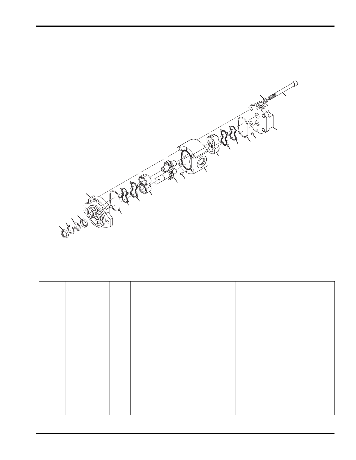
38.1 Reel Motor
1
2
3
4
5
5
6
6
7
7
8
8
9
10
11
12
13
14
2
10
Part Number 4140034
TR320
Serial No. All
Item Part No. Qty. Description Serial Numbers/Notes
1
● 2 N/S 2 Seal, Shaft
3 N/S 1 Snap Ring
4 N/S 1 Back Up Washer
● 5 N/S 2 Seal, Section
● 6 N/S 2 Anti-Extrusion
● 7 N/S 2 Seal, Thrust Plate
8 N/S 2 Thrust Plate
9N/S1Gear Set
10 N/S 2 Dowel Pin
11 N/S 1 Body, Motor
12 N/S 1 Rear Cover
13 N/S 4 Screw, M8 x 115 mm SHCS
14 N/S 4 Flat Washer
● A809615 1 Seat Kit Includes items marked ●
N/S 1 Front Cover
> Change from previous revision
75
Page 90

TR320
1
2
3
4
5
6
7
8
9
10
39.1 Steering Cylinder
Part Number 4244289
Serial No. All
76
Page 91

TR320
Item Part No. Qty. Description Serial Numbers/Notes
1
2 N/S 1 Rod and Piston Assembly
3 ● 1 Seal, Piston
4 ● 1Wiper, Piston
5 N/S 1 Gland, Cylinder
6 ● 1 O-Ring, Gland
7 ● 1 Seal, Gland
8 ● 2 Wiper Seal
9 ● 1 Seal, Tube
10 ● 2 Wiper, Tube
● 4291657 1 Seal Kit Includes Items marked ●
N/S 1 Tube, Cylinder
> Change from previous revision
77
Page 92

TR320
3
1
2
4
5
6
7
8
9
40.1 Front Lift Cylinder
Part Number 669395
Serial No.
78
Item Part No. Qty. Description Serial Numbers/Notes
1
2N/S1Gland
3N/S1Rod
4 N/S 1 Snap Ring
5N/S1•O-Ring
6 N/S 1 • Inner Bearing
7 N/S 1 • Seal, Gland
8 N/S 1 • Outer Bearing
9N/S1•Wiper
N/S 1 Cylinder
4369206 1 Seal Kit
> Change from previous revision
Page 93

41.1 Rear Lift Cylinder
1
2
3
4
5
6
7
8
9
Part Number 670815
TR320
Serial No. All
Item Part No. Qty. Description Serial Numbers/Notes
1
2N/S1Gland
3N/S1Rod
4 N/S 1 Snap Ring
5N/S1•O-Ring
6 N/S 1 • Inner Bearing
7 N/S 1 • Seal, Gland
8 N/S 1 • Outer Bearing
9N/S1•Wiper
N/S 1 Cylinder
4369206 1 Seal Kit
> Change from previous revision
79
Page 94

1
2
3
4
5
6
7
8
9
10
11
12
26
27
28
27
13
14
16
17
18
19
20
21
22
23
●
●
●
15
●
●
●
24
25
15
TR320
42.1 Steering Valve
Part No. 4393849
Serial No. All
80
Page 95

TR320
Item Part No. Qty. Description Serial Numbers/Notes
1
2 N/S 1 Stop, Ball
3 N/S 1 Thin Bearing Race
4N/S1Bearing
5 N/S 1 Thick Bearing Race
6 N/S 1 Spool
7 N/S 1 Spring Retaining Ring
8N/S1Cross Pin
9N/S1Sleeve
10 N/S 1 Set, Spring
11 N/S 1 Check Valve, Ball
12 N/S 3 Screw, Special
● 13 N/S 5 O-Ring
14 N/S 1 End Cover
● 15 N/S 2 O-Ring
16 N/S 1 Rim, Gearwheel
17 N/S 1 Gearwheel
18 N/S 1 Distributor Plate
● 19 N/S 1 O-Ring
20 N/S 1 Spacer
21 N/S 1 Cardan Shaft
22 N/S 1 Housing
23 N/S 1 Relief Valve
24 N/S 1 Spring, Relief Valve
● 25 N/S 1 Seal, Shaft
26 339909 3 O-Ring, -6 ORFS
27 339908 2 O-Ring, -4 ORFS
28 N/S 3 Screw, Special
N/S 1 Ball, Emergency Steering
Adjust the Check Valve to 1500 psi
(103 BAR)
● 4197940 1 Seal Kit Includes Items marked ●
> Change from previous revision
81
Page 96

TR320
19
18
2
16
6
10
7
11
17
1
23
22
14
15
20
21
4
8
9
5
3
12
13
43.1 Gear Pump
Part Number 4134071
Serial No. All
82
Page 97

TR320
Item Part No. Qty. Description Serial Numbers/Notes
1
2 N/S 1 Front Cover
3 N/S 1 Twin Rear Cover
4 N/S 1 Thrust Plate
5 N/S 1 Thrust Plate
6 N/S 1 Thrust Plate
7 N/S 1 Thrust Plate
8 N/S 1 Drive Gear
9 N/S 1 Driven Gear
10 N/S 1 Drive Shaft
11 N/S 1 Driven Gear
12 N/S 4 Screw, M10 X 135mm
13 N/S 4 Washer
● 14 N/S 1 O-Ring
● 15 N/S 2 Seal
● 16 N/S 2 Seal
● 17 N/S 1 Seal, Square Section
● 18 N/S 1 Seal, Shaft
19 N/S 1 Ring, 30mm
● 20 N/S 2 Antiestrusion
● 21 N/S 2 Back-Up Ring
22 N/S 1 Hub
23 N/S 2 Dowel Pin
N/S 1 Body
● TBD 1 Seal Kit Includes Items marked ●
> Change from previous revision
83
Page 98

TR320
44.1 Traction Pump
Part Number 4203740
Serial No. All
20
60
50
19
44
45
3
49
47
3
48
37
34
33
35
32
36
1
2
10
12
8
9
11
7
15
14
16
13
46
6
5
4
57
55
56
55
59
51
54
53
17
52
41
43
42
23
22
58
21
26
25
18
52
24
84
31
30
29
28
40
39
38
42
43
27
41
Page 99

TR320
Item Part No. Qty. Description Serial Numbers/Notes
1
2 1 Thrust Plate 3103218
3 2 Trunnion BearingKit 4800470
4 1 Seal, Shaft 5000689
•
5 1 Washer, Seal Support 4350455
6 1 Retaining Ring, Internal 9006200-0281
7 1 35 cc Cylinder Block Kit
8 1 • Guide, Slipper Retainer
9 3 • Pin, Slipper Holddown
10 9 • Piston Assembly, 35 cc
11 1 • Retainer, Holddown Pin
12 1 • Retainer, Slipper
13 1 • Retaining Ring
14 1 • Spring, Cylinder Block
15 1 • Washer
16 1 • Retainer, Spring
17 1 Valve Plate
18 1 Slotted Pin
19 1 Charge Relief Plug 4800308
20 4224121 1 • O-Ring 001149 (9004201-6200)
21 1 Shim Kit 4510027
22 1 Spring, Charge Pressure 4800714
23 1 Poppet 1200359
24 1 End Cap w/ loop flushing
25 1 Gasket, End Cap
•
26 1 Bearing, Needle
27 4 Screw
28 1 Plug Assembly
29 1 • O-Ring
•
30 1 Spring
31 1 Spool
32 1 Neutral Return Arm Assembly 4250244
33 1 • Cam Bearing 5000718
34 1 • Retaining Ring 5000720
35 1 • Spring, Neutral Return 11026378
36 1 • Pivot, Neutral Return 4250246
37 1 • Nut, Seal 505412 (9003509-0008)
•
38 1 Bypass Valve Assembly 4461332
39 1 • Back-Up Ring 0714472 (9006110-0120)
•
1 Swashplate 11034329
40 1 • O-Ring 5000654
•
41 2 SCR Valve, 280 BAR (4060 psi) 4350638
42 1 • O-Ring 001131 (9004201-5000)
•
> Change from previous revision
85
Page 100
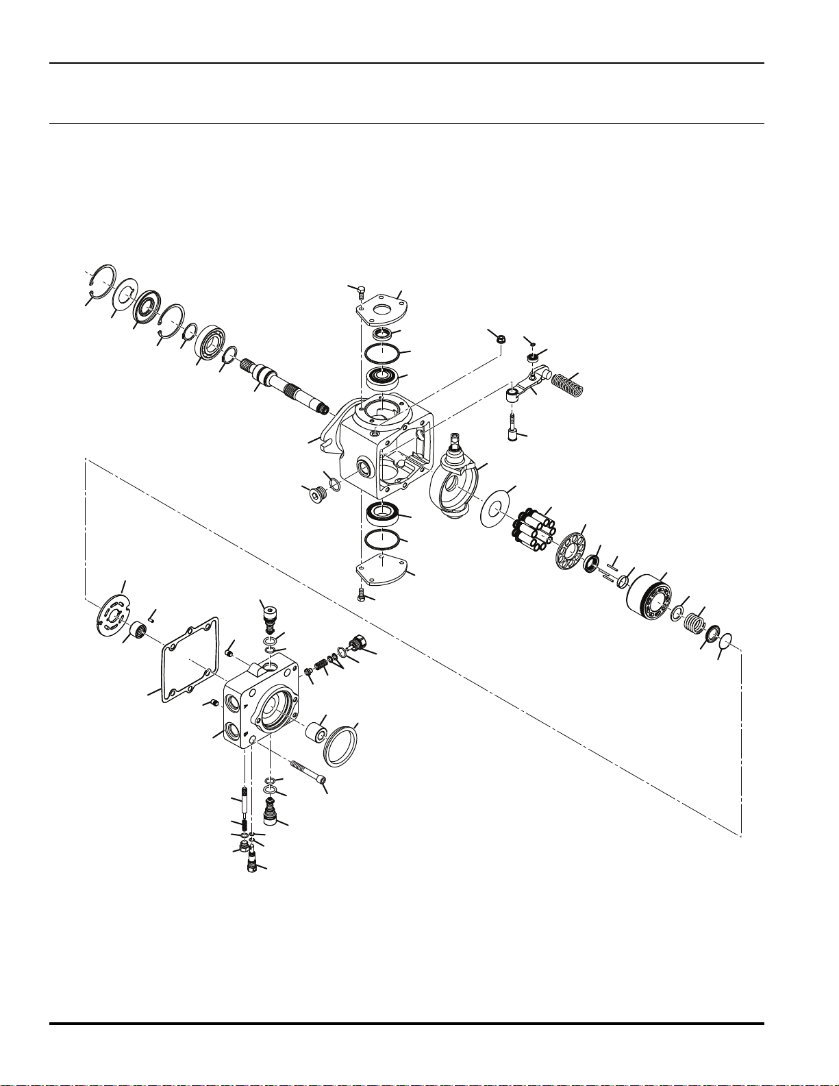
TR320
1
2
3
3
4
5
6
7
8
9
10
11
12
13
14
15
16
17
18
19
20
21
22
23
24
25
26
27
28
29
30
31
32
33
34
35
36
37
38
39
40
46
47
48
49
50
41
41
42
42
43
43
44
45
56
57
58
59
60
51
52
52
53
54
55
55
44.1 Traction Pump (Continued)
Part Number 4203740
86
 Loading...