

Page 1

Safety, Operation and Maintenance Manual
Jacobsen MH5™
Frame With Oil Cooler, Less Cutting Units
Series: KT
Product Code LBMA405
Frame Less Oil Cooler And Cutting Units
Series: KU
Product Code LBMA406
Sportcutter 8 inch 8 knife Left Hand floating Head Cutting Unit
Series: AD2
Product Code: LMAC603-L
25077G-US-R1
Sportcutter 8 inch 8 knife Right Hand floating Head Cutting Unit
Series: AE2
Product Code: LMAC603-R
Sportcutter 8 inch 6 knife Left Hand floating Head Cutting Unit
Series: AB2
Product Code: LMAC604-L
Sportcutter 8 inch 6 knife Right Hand floating Head Cutting Unit
Series: AC2
Product Code: LMAC604-R
Verticut Left Hand floating Head Cutting Unit
Series: AF2
Product Code: LMAC605-L
Verticut Right Hand floating Head Cutting Unit
Series: AG2
Product Code: LMAC605-R
Frame With Oil Cooler And 8"- 8k Floating Head Units
Series: JB2
Product code: LKDA304
WARNING
WARNING: If incorrectly used this machine can cause severe injury. Those who use and maintain this machine
must be trained in its proper use, warned of its dangers and must read the entire manual before attempting to set
up, operate, adjust or service the machine.
US
United States
of America
RJL 100 July 2014
Page 2

Section Page
INTRODUCTION
2.1 Important .................... .......................... .......................... ........... 3
2.2 Product Identification ................................................................ 4
2.3 Guidelines For The Disposal Of Scrap Products ...................... 5
2.3.1 During Service Life .................................................................... 5
2.3.2 End Of Service Life ................................................................... 5
2.4 Parts Manual ............................................................................. 6
SAFETY
3.1 Operating Safety........................................................................ 7
3.1.1 Operating Instructions 8
3.1.2 Safety Signs .............................................................................. 7
3.1.3 Starting The Engine .................................................................. 8
3.1.4 Tra nsporting .................... ..................... .......................... ........... 8
3.1.5 Slopes ... .......................................... ......................................... . 9
3.1.6 Blocked Cutting Units ...................... ..... ..... ............................... . 9
3.1.7 Adjustments, Lubrication, Maintenance & Cleaning ................ 10
SPECIFICATIONS
4.1 Dimensions & Weights ............................................................. 11
4.2 Machine Specification .............................................................. 12
4.3 Hydraulic Specification ............................................................. 12
4.4 Cutting Unit Specification.......................................................... 12
4.5 Recommended Lubricants ....................................................... 12
4.7 Cutting Performance (Area) ..................................................... 12
4.8 Cutting Performance (Frequency)............................................. 12
DECALS
5.1 Safety Decals ........................................................................... 14
5.1 Instruction Decals ..................................................................... 14
CONTROLS
6.1 Cutting Cylinder Drive .............................................................. 16
OPERATION
7.1 Daily Inspection ........................................................................ 17
7.2 Operating Procedure ................................................................ 18
7.3 Attaching The Mower To The Tractor ...................................... 19
7.4 Removing The Machine From The Tractor .............................. 21
7.5 Mowing ................................................................................ ..... 22
7.6 Transporting ............... .......................... .......................... .......... 22
7.7 Cutting Performance ................................................................ 23
7.8 Unblocking Cutting Units .......................................................... 23
7.9 Backlapping ............................................................................. 23
MAINTENANCE AND LUBRICATION
8.1 Maintenance & Lubrication Chart ............................................. 25
8.2 Lubrication ............................................................................... 26
8.3 During Overhaul........................................................................ 28
ADJUSTMENT
9.1 Height Of Cut Adjustment ........................................................ 29
9.2 Cutting Reel Adjustment .......................................................... 30
QUALIT Y OF C U T
10 Quality Of Cut Troubleshooting ................................................ 31
10.1 Washboarding ............ ..................... ..................... ............... ..... 31
10.2 Marcelling ................... .......... ........... .......... ........... .......... .......... 32
10.3 Step Cutting ............................................................................. 33
10.4 Scalping ..................... ......................................................... ..... 34
10.5 Stragglers ............. ...... ..... ............................... ...... ..... ..... ..... ..... 35
10.6 Streaks...................................................................................... 36
10.7 Windrowing ............................................................................... 37
10.8 Rifling Or Tramlining ................................................................ 38
10.9 Mismatched Cutting Units ........................................................ 38
GUARANTEE
11.1 Warranty ................................................................................... 39
Section Page
Ransomes Jacobsen Limited reserves the right to make design changes without obligation to make these changes
on units previously sold and the information contained in this manual is subject to change without notice.
© 2014, Ransomes Jacobsen Limited. All Rights Reserved
Page 3

INTRODUCTION 2
2.1 IMPORTANT__________________________________________________________
The Jacobsen Hydraulic 5 is a tractor mounted reel mower. The cutting units are driven by a two-port hydraulic
pump, driven by the Tractor output shaft.
IMPORTANT: Do the maintenance indicated in this manual to make sure that the quality of cut is kept at a high
level.
This Manual is part of the machine and must stay with the machine always. The suppliers of new, or used,
machines need to keep this documentation and supply the owners with a copy.
You must use the machine to cut the grass only and not for any other purpose. The Compliance with these conditions of The operation, service and repair specified by the manufacturer, are understood to be part of the correct use.
ALL operators MUST read through this manual and understand the Safety Instructions, controls, lubrication and
maintenance procedures.
Make sure that you obey all safety and road traffic regulations.
You must not make any changes to the machine that are not approved by the manufacturer. This type of change
can release the manufacturer from the liability for any damage or injury.
Discard of worn parts in alignment with all local environment protection regulations. Use the local systems available in the country where the machine is used, for these recycled materials. When the machine is at its end of
life, there are guidelines in this manual for the removal of the machine from use.
Use only Jacobsen Genuine spare parts to meet the machine type approval regulations specified by the European Union.
2006/42/EC
These instructions are the Original instructions confirmed by Ransomes Jacobsen Limited
en-3
Page 4
2 INTRODUCTION
B
Kg
Kw
Kg
Kg
West Road
Ransomes Europark
Ipswich IP3 9TT
England
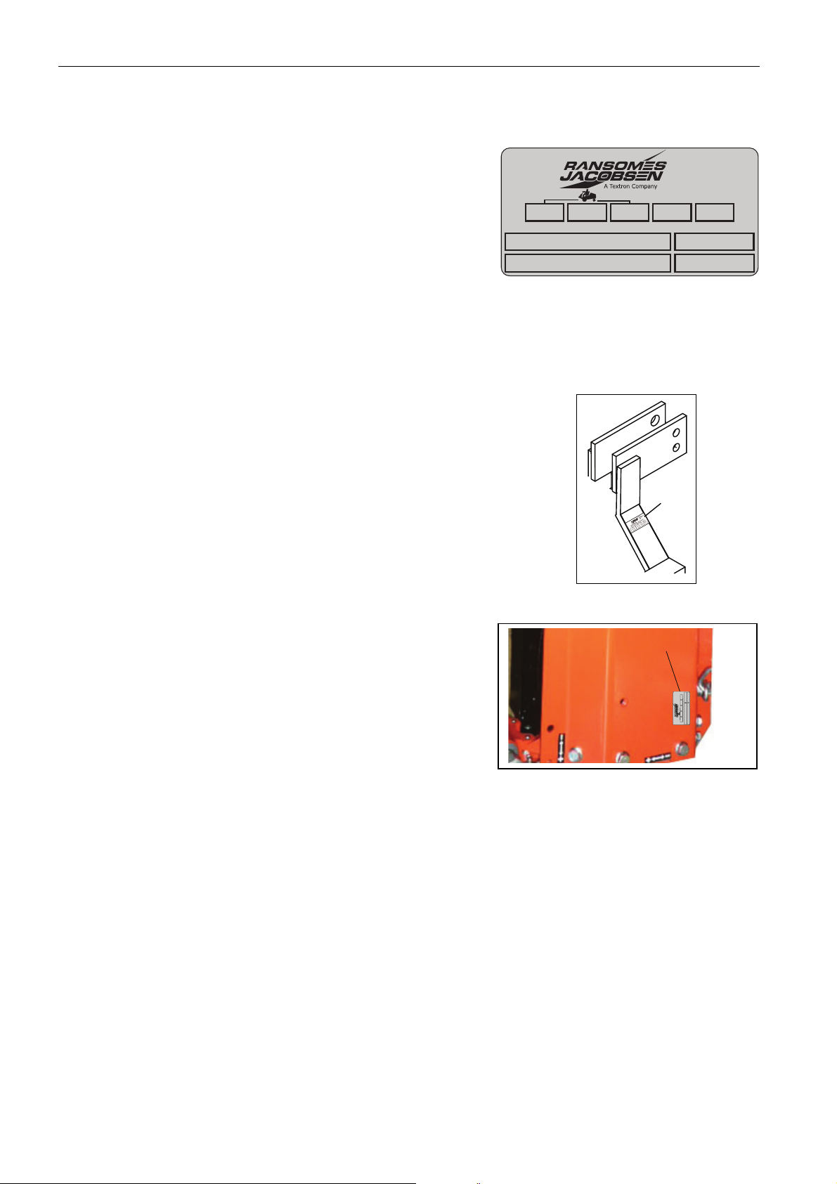
2.2 PRODUCT IDENTIFICATION___________________________________________
A Maximum front axle load in Kg (for all machines being driven
on the highway)
B Weight-Mass in Kg
C Maximum rear axle load in Kg (for all machines being driven
on the highway)
D Power Rating in Kw
E Date code
F Machine type (Name)
G Product code
H Product name
J Serial number
Location of Serial number plate
The serial number plate (A) is found on the main frame upper tractor mount.
A
KgKwKg
B
F
H
West Road
Ransomes Europark
Ipswich IP3 9TT
England
CD
Kg
A
E
G
J
Cutting Unit
The cutting unit serial plate (B) is located on the unit top plate.
en-4
Page 5

INTRODUCTION 2
2.3 GUIDELINES FOR THE DISPOSAL OF SCRAP PRODUCTS _________________
2.3.1 DURING SERVICE LIFE _________________________________ ______________
All the used fluids and parts must be controlled as hazardous materials material. Recommended procedures must be
followed for their safe removal.
If a fluid leak occurs, contain the spill to make sure that the leak does not flow into the ground or drainage system.
Follow the regulations in force to make sure that leaks are controlled.
The maintenance procedures in this manual make sure that the damage that the machine can cause in the local
environment is controlled.
When the machine completes its full service life, the following actions must be taken.
2.3.2 END OF SERVICE LIFE _______________________________________________
These guidelines must be used with applicable Health, Safety and Environmental laws. Always use the approved local
waste disposal and agencies for recycled materials.
• Park the machine in an applicable area to use all of the necessary lifting equipment.
• Use correct tools and Personal Protective Equipment (PPE) and take instruction from the technical
manuals applicable to the machine.
• Remove and store correctly
1. Batteries
2. Fuel
3. Engine coolant
4. Oils
• Read the Technical Manual before you begin to disassemble the machine. Plan the disassembly, give
attention to parts that are in a state of mechanical pressure or contain stored energy e.g springs.
• Items that continue to have a service life must be separated and returned to the local dealer.
• Items that are worn must be separated into the material groups and removed according to the agencies
for the recycled materials that are available. Common examples.
• Steel
• Non ferrous metals
• Aluminium
• Brass
• Copper
• Plastic materials
• Identified
• Can be recycled
• Can not be recycled
• Not identified
• Rubber
• Electrical and Electronic Comp onents
• Some parts are not easily separated e.g Hydraulic hose. These materials must be added to the
“General discarded materials” area.
• Do not burn discarded materials.
Change the machinery records to show that the machine is not in operation and is discarded. Supply this serial number
to The Jacobsen Warranty Department to close their records.
en-5
Page 6

2 INTRODUCTION
2.4 PARTS MANUAL ___________________________ ___________________________
To meet the standard ISO14001, Jacobsen does not send a paper parts manual with every product.
To refer to the parts list for this mower you have four options:
1. Website – www.Jacobsen.com. Select the “GENUINE PARTS” tab followed by the “ONLINE PARTS
LOOK-UP” tab. These pages will show the parts list and the line drawings you need to help with the
identific ation of spare parts.
2. Website – www.Jacobsen.com. Select the “CUSTOMER CARE” tab followed by the “MANUALS” tab.
You have the option to view or “Download” a PDF version of the parts manual.
3. Complete the form included in the technical manual pack supplied with the machine for one of the two
options below
a. A disc that contains an electronic copy of the Parts Book.
b. A paper copy of the parts manual.
en-6
Page 7

SAFETY 3
!
3.1 HOW TO OPERATE SAFELY _____________________________________________
WARNING
EQUIPMENT THAT IS NOT OPERA TED CORRECTL Y OR BY PERSONNEL WITHOUT TRAINING CAN
BE DANGEROUS.
Know the location and c orrect use of all controls. Befor e any use of the machi ne, personnel w ithout training
must receive instruction from personnel with experience in the machines operation.
3.1.1 Safe operation
a) Read the instructions carefully. Know the
controls and the correct use of the
equipment;
b) Children or persons who do not understand
these instructions must not use the
machine. The Local regulations will set the
age of the operator;
c) Never use a machine near persons,
including children or animals;
d) Remember that the operator or user is
responsible for accidents or hazards that
occur to other persons or their property.
e) Do not carry passengers;
f) All drivers must get instruction. That
instruction must include:
- A need for careful attention when you use a
“ride-on” class machine.
- The loss of traction on slopes or in a
condition of decreased traction, is not
always corrected by an application of the
brakes.
Reasons for the loss of control.
i) Not enough wheel grip;
ii) Driving at more than the safe speed for the
conditions
iii) You over brake or brake suddenly.
iv) The type of machine is wrong for the job;
v) No attention given to the ground conditions
or operating slopes;
vi) Incorrect hitch and load distribution.
3.1.2 Preparation
a) When you operate the machine, always
wear strong footwear and long trousers. Do
not operate the equipment without the
correct footwear.
b) Inspect the area you are to cut. Objects or
any particles in the area are a safety risk.
Remove these objects. These objects can
damage the blades or cause injury to any
person near.
c) WARNING - Diesel and Petrol are
flammable.
- Store in clean applicable metal containers.
- Refuel outdoors only and do not smoke
when you add fuel;
- Refuel the machine before you start the
engine. When the engine is hot, do not
remove the fuel tank cap or add fuel to the
tank.
- If any fuel spills, do not try to start the
engine, but move the machine away from
the area. Until the fuel vapors have gone
keep any supply of ignition at a distance.
- Replace all fuel tank and container caps
correctly;
d) Replace any damaged or broken silencers.
e) Visually inspect the machine use. Check
the blades, blade bolts and the deck
assembly for wear or damage. Replace all
the blades in a group to keep the balance;
f) On those machines with many blades, be
careful when you rotate one blade, it can
cause other blades to rotate.
3.1.3 Operation
a) Do not operate the engine in a closed
space. The gas Carbon Monoxide is part of
the exhaust gas mix. In a closed space this
gas can reach dangerous levels
b) Use a mower only in daylight or in good
artificial light;
c) Before you start the engine, disengage all
blade attachment clutches and shift into
neutral;
d) Do not use on slopes of more than the
recommended angle;
NOTE The recommended angle is calculated as
shown in BS EN ISO 5395-3:2013 clause
4.6.1, 4.6.2, 4.6.3.
en-7
Page 8

3 SAFETY
e) Remember there is no safe slope. Operate
with caution on grass slopes.
To guard against a turn over
- Do not stop or start suddenly when you
operate on a slope.
- To operate on a down slope, prevent sharp
movements on the controls and always
keep the machine in gear.
- Go slowly when you operate on slopes and
when you make tight turns;
- Look for any changes in the cutting surface
that can change the mowers balance.
- Never use the mower to move across a
slope on a diagonal line. Unless the
machine is for this purpose;
f) When you pull a load or use accessories,
be careful.
- Use only approved drawbars;
- Any load must not change your full control
of the machine.
- Do not turn suddenly. Be careful when you
move in a reverse direction;
- Use the counterweight or wheel weights
recommended in the instruction handbook;
g) Be careful of those around you and the
users of the road when you move across or
near roadways;
h) Stop the blades before you move across
any surface different from grass;
i) Do not allow the deck outlets to point at
other persons. Do not allow persons near a
machine that you operate.
j) Do not operate the machine with damaged
guards or without safety devices in
position;
k) Do not change the engine governor
settings or operate at more than the
specified engine turns. If you operate the
engine at more than the suppliers set
speed, you increase the hazard of personal
injury;
l) When you leave the position for operation,
disengage the drive and lower the
attachments to the ground.
- Engage neutral and set the parking brake;
- Stop the engine and remove the key;
m) Before you check, clean or work on the
machine.
Disengage the drive to the attachments,
stop the engine and remove the ignition
key:
- When you hit an object, inspect the
machine for damage and make the repairs
before you restart and operate the
equipment;
- If the machine starts to make a sound that
is not normal or begins to cause vibration,
check immediately;
n) When the machine is not in operation or
during transport. Disengage the drive to the
attachments.
Before you refuel or you mak e height
adjustment , un l es s t he adj ustment is made
with the operator in the seat. Stop the
engine and disengage drive to
attachments.
Decrease the throttle setting during the
engine “run-out”. If the engine has a fuel
valve, turn the fuel valve to the OFF
position at the end of operation.
3.1.4 Maintenance and storage
a) Keep all nuts, bolts and screws tight to
make sure the equipment is in safe work
condition;
b) Do not store the equipment with fuel in the
tank. The Fuel vapour can become a
danger in closed spaces.
c) When you store in a closed space, allow
the engine to become cool first;
d) Replace worn or damaged parts for safety;
e) If the fuel tank is drained, drain in an area
with good ventilation.
and:
a) On those machines with many blades, be
careful when you rotate one blade, it can
cause other blades to rotate.;
b) When the machine is parked for an
extended period or put into storage, lower
the cutting device unless a positive
mechanical lock is used.
en-8
Page 9

SAFETY 3
3.1.5 Important Safety Notes_________________________________________________
This safety alert symbol indicates possible hazards.
DANGER:
Indicates a condition state that WILL
WARNING:
Indicates a condition state that CAN cause death or injury.
CAUTION:
Indicates a condition state that can cause injury and damage to property. Also indicates work procedures that
are not safe.
IMPORTANT:
Only drive the machine at the road speed when you are on a highway. You must not select road speed on grass
areas, rough roads or gravel tracks.
cause death or injury.
Some of the illustrations in this manual can show shields, guards or plates removed for accuracy. You must not
operate this equipment without these devices fastened in position.
WARNING
1. To leave the position for operation, for any reason:
a. Return the traction pedal to the Neutral position.
b. Disengage all drives.
c. Lower all equipment to the ground.
d. Engage the parking brake.
e. Stop the engine and remove the ignition key.
2. Keep your hands, feet an d clothing away f rom moving parts. Wait for all
movement to stop before you clean, adjust or service the machine.
3. Keep all persons and animals away from the area of operation.
4. Never carry any passengers, unless a seat is supplied for that purpose.
5. Never operate the equipment without a correctly fastened grass
deflector in position.
If you follow all the instructions in this manual, you increase the life of your machine and keep its maximum
performance. Adjustments and maintenance must always be done by an approved technician.
For additional service information or service instruction, contact your Authorized Ransomes Jacobsen Dealer.
en-9
Page 10

3 SAFETY
WARNING
If the Machine, Has An Operator Ear Sound Level Of More Than 85 Db(A) Leq.
You Must Wear Applicable Ear Protection.
WARNING
To Prevent Injury From The Hydraulic Oil, Which Is At High Pressure And Work Temperature, Do Not Use The
Hydraulic Oil At High Pressure Has Enough Force To Enter Through The Skin. If The Fluid Enters Through The
Skin, The Fluid Must Be Removed Within Hours. Immediately Get Attention By A Medical Professional Or
Personal Protective Equipment (PPE), for example Safety Glasses, Footwear, Hard Hats, Work Gloves And
Ear Protection Must Be Used. Ransomes Jacobsen Recommends That The Owner Of The Machine Completes
All Persons Who Use This Machine Must Accept Training By An Approved Person. The Training Must Include
All Of The Machine Systems, Controls and The Safety Devices Before These Persons Use The Machine.
Hands To Check For Oil Leaks. Make Sure That You Use A Piece Of Paper Or Cardboard.
Gangrene May Result.
CAUTION
The Local Risk Assessment And Supplies All The Necessary PPE.
en-10
Page 11

SPECIFICATIONS 4
4.1 ENG INE SPECIFICATION ______________ __ ___ __ __ ___ ____________________
The Hydraulic 5 is driven by the tractor power take off shaft.
4.2 DIMENSIONS & WEIGHTS ________________________________________________
A Width of Cut: 135 inch 343 cm
B Overall Width Cutting: 142 inch 361 cm
C Overall Width Transport (minimum): 98.5 inch 250 cm
D Overall Length: 43.7 inch 111 cm
E Overall Height 38.6 inch 98 cm
Weight of Machine, Hydraulic Tank Full 1323 lb 600 kg
Weight of one 8 Knife Cutting Unit (Floating) 209.5 lb 95 kg
Weight of one Verticut Cutting Unit 209.5 lb 95 kg
4.3 MACHINE SPECIFICATION_____________________________________________
Frame construction: Type, Welded and bolted hollow box section frame;
Cutting unit drive: Fixed displacement hydraulic motors with cutting cylinder drive control levers for
forward and reverse Backlappi ng.
Transmission: PTO from tractor to gearbox mounted on main frame, through tandem hydraulic
pump to hydraulic valve then to cutting unit hydraulic motors.
Tractor Requirements: Lift System Attaches to tractors with category 1 or 2 three point linkage.
Standard 1.6 inch (40mm). diameter, 6-spline 540 rpm power take off shaft.
Minimum Tractor Power: 40hp (29.5 kW)
en-11
Page 12

4 SPECIFICATIONS
4.4 CUT TIN G UN IT SPECIFICATION_____________ ___ __ _____________________ __
Sportcutter Verticut
Construction Heavy-duty pressed steel bolted construction
Reel Length 30 inch (762mm) 30 inch (762mm)
Number of Knives 6 N/A
Number of Blades N/A 54
Reel Diameter (New) 7.75 inch (197mm) N/A
Minimum Reel Diameter (Before Replacement) 7.0 inch (178mm) N/A
Floating Head Height of Cut (Standard Blade) 0.5 inch - 1.4 inch (12.7mm - 35.7mm)
Floating Head Height of Cut (Thin Blade) 0.35 inch - 1.27 inch (9mm - 32mm)
Rear Roll 2.4 inch (60mm) Diameter
Height of Cut Adjustment Adjustable screw system on front & rear roll
Transmission By hydraulic motor through gear & pinion to reel.
Maximum Reel Speed at 540 rpm PTO Speed 1240rpm
NOTE
These cutting units are made to cut grass of maximum height 4 inch (100mm) down to the available height of cut
range.
4.5 CUTT IN G PER FOR M A NCE____________________ __ __ ___ __ __ ______________
10 acre / hour at 7.5 mph
4.1 hectares / hour at 12 km
10% allowance is included for normal overlaps and turning at the end of each cut.
6-blade Floating Head: 53 cuts/y at 5 mph
6-blade Floating Head: 58 cuts/m at 8 km/h
8-blade Floating Head: 71 cuts/y at 5 mph
8-blade Floating Head: 78 cuts/m at 8 km/h
.
en-12
Page 13

SPECIFICATIONS 4
en-13
Page 14

5 DECALS
A
B
C
D
E
F
5.1 SAFETY DECALS EC__________________________________________________
5.2 INSTRUCTION DEC ALS EC
A
en-14
Page 15

5 DECALS
Safety Decals
A. 009034910 Read Operator's Manual.
B. 009034890 Keep a Safe Distance from the Machine.
C. 009034940 Caution Rotating Blades.
D. 009034930 Avoid Fluid Escaping Under Pressure. Read Operators Manual for Service Procedures.
E. 009034900 Do Not Remove Safety Shields While Engine is Running.
F. 4164860 Caution Power Take Off Shaft
Instructi on De c al s
A. Cutting Cylinder Forward / Neutral / Reverse
en-15
Page 16

6 CONTOLS
6.16 CUTTING C YL IN D ER DRIVE _____________________ __ ___ __ __ ___ __ _________
The levers A and B operate the cutting cylinder drive. The
direction of drive is indicated by the decal
illustrate d. Directions are given from the Operators
seated position
Lever A controls cylinders 1, 2 and 4. Lever B controls
cylinders 3 and 5. Select the cutting pattern required and
select accordingly.
To operate:
(a) Pull the lever forward to engage drive for grass
cutting.
(b) Push the lever rea rward for reverse drive which
is used for Backlapping or clearing of cylinders.
(c) When drive is not required the lever should be
in the neutral (N) position.
REAR
4 5
CUTTING CYLINDER LAY OUT
2
1
3
FRONT
en-16
Page 17

OPERATION 7
7.1 DAILY INSPECTION____________________________________________________
CAUTION
The Daily Inspection Should Be Per-
formed Only When The Tractors
Engine Is Off And All Fluids Are Cold.
Lower Implements To The Ground,
Engage Tractors Parking Brake, Stop
Engine And Remove Ignition Key.
1. Perform a visual inspection of the entire unit, look for signs of wear, loose hardware and missing or
damaged components. Check for oil leaks to ensure connections are tight and hoses and tubes are in
good condition.
2. All fluids must be at the full mark when cold. See 8 - MAINTENANCE and LUBRICATION
3. Make sure all cutting units are adjusted to the same height of cut.
en-17
Page 18

7 OPERATION
7.2 OPERATING PROCEDURE ______________________________________________
CAUTION
To Help Prevent Injury, Always Wear
Safety Glasses, Leather Wo rk Shoes Or
Boots, A Hard Hat And Ear Protection.
1. Do not operate with loose, damaged or missing components. Whenever possible mow when grass is
dry
2. First mow in a test area to become thoroughly familiar with the operation of the controls.
3. Study the area to determine the best and safest operating procedure. Consider the height of the grass,
type of terrain, and condition of the surface. Each condition will require certain adjustments or
precautions.
4. Never direct discharge of material toward bystanders, nor allow anyone near the machine while in
operation. The owner/operator is responsible for injuries inflicted to bystanders and/or damage to their
property.
5. Use discretion when mowing near gravel areas (roadway, parking areas, cart paths, etc.). Stones
discharged from the implement may cause serious injuries to bystanders and/or damage the
equipment.
CAUTION
Remove All Debris From The Site Before
Mowing. Enter A New Area Cautiously
Always Operate At Speeds That Allow
You To Have Complete Control Of The
Mower.
6. Disengage the cutter motors and raise the implements when crossing paths or roads. Look out for
traffic.
7. Stop and inspect the equipment for damage immediately after striking an obstruction or if the machine
begins to vibrate abnormally. Have the equipment repaired before resuming operation.
CAUTION
Before You Clean, Adjust, Or Repair
This Equipment, Always Disengage All
Drives, Lower Implements To The
Ground, Engage Tr acto r Pa rkin g Brake,
Stop Engine And Remove Key From
Ignition Switch To Prevent Injuries.
10. Do not operate with loose, damaged or missing components.
en-18
Page 19

OPERATION 7
B
A
C
7.3 ATTACHING THE MOWER TO THE TRACTOR P.T.O. SHAFT __________________
A standard P.T.O. shaft is provided and this will have to be
shortened in length to suit the tractor being used. It is
essential that no more than is necessary is cut off as
maximum engagement of the sliding portion is needed to
prevent excessive wear.
Adequate removal of sharp edges and chamfering of the
cut ends must be carried out.
NOTE
On certain tractors it will be impossible to lift the machine to the maximum height on the three point linkage
without the sliding part of the P .T.O. shaft disengaging. Stops must be set correctly on the tractor lift quadrant to
limit the lift height to prevent the disengagement of the P.T.O. shaft.
2. Stop the tractor engine.
3. Connect the tractor lower lift arms to the 2-hitch
points (A) on the main crossbeam, using the
lower hole in the hitch plates to fit the
connecting pins and spring clips.
Connect the tractor top link (B) to the machine.
IMPORTANT
Select the pair of holes in the 'A' frame which
allows the top link to take up as near a horizontal
position as possible.
2. Fit pin (B) and secure with pin and spring ring.
3. Extend the top link and remove the stabiliser pin
from the rear of the unit pivot support plates.
Stow this pin in the holes in the lugs at the front
of the main crossbeam and secure with spring
pins.
4. Shorten the top link until the 'A' frame becomes vertical. Attach the jubilee clip (supplied) to the top link
up against the end of the turn buckle and tighten securely in this position.
5. Connect up P.T.O. shaft (C) to the machine and tractor.Connect lift hose QRC to Tractor QRC.
en-19
Page 20

7 OPERATION
1. Start the tractor engine and lift the machine fully by means of the tractor lifting quadrant lever.
2. Switch off the engine.
3. Adjust the tractor RH lift rod length to level the main crossbeam of the machine.
4. Measure the height of the crossbeam from the ground at each end to ensure the machine is level.
5. Adjust the length of the check chains so that there is a minimum of slack when the tractor arms are
fully raised. This will prevent excessive side swing of the machine when transporting.
NOTE
If external tractor check chains are fitted, they should be adjusted so that no part of the lift arms can foul
against the hydraulic pump or any of the fittings when the machine is in the cutting position. This will prevent
excessive side swing of the machine when transporting.
Before this adjustment can be made, the height of cut of all three units must be set accurately with the machine
on a level, hard surface (see page 23). The ‘A’ frame must be vertical.
On the area to be cut, make an initial cut of approximately 20 metres. Examine the finish of cut across the width
of the swathe - it is likely that the 2-front units will be cutting lower than the rear unit. If necessary, to obtain an
even cut, extend the top link by 1½ to 2 turns.
IMPORT ANT
Do not lengthen the top link by more than 3 turns; the need for adjustment in excess of this indicates that the
height of cut settings on the units were not equal initially.
Any subsequent changes in height of cut will not effect the length of the top link; but it is important that is the units
are set up by using spacers between the ground and bottom blade, the top link should be shortened to its original
length, ie. until the turnbuckle contacts the jubilee clip. After resetting the height of cut by this method, the top link
should again be lengthened by the same amount.
NOTE
Alternatively, the height of cut setting on the individual units can of course be adjusted slightly to obtain an even
finish without altering the length of the top link.
en-20
Page 21

OPERATION 7
A
B
7.4 REMOVING THE MACHINE FROM THE TRACTOR __________________________
To remove the machine from the tractor, reverse the attachment instructions.
1. The stabiliser pin (A) must be in place over the
rear unit trailing arm (B) before the machine is
removed from the tractor 3-point linka ge; this
ensures that the machine is stable when
removed from the tractor.
2 The stabiliser pin MUST always be removed
from over the rear unit trailing arm (A) for all
mowing and transporting operations. When not
used store the pin in location (B) to prevent loss.
REMEMBER: It is not necessary at anytime when assembling or removing the mower from the tractor to
dismantle, or disturb, any hydraulic pipe joints or components. should servicing be necessary during use, it must
be carried out by a trained service person.
NOTE
This instruction applies to the centre and wing units
en-21
Page 22

7 OPERATION
7.5 MOWING_____________________________________________________________
1. Start the tractor and lower the lift arms.
2. E ng age the tra ct or P.T.O.
3. Select tractor gear ready to move off.
4. Move the mower control levers forwards to engage the forward drive to the cutting units.
CAUTION
Always put the drive controls in the neutral position and switch off the engine before dismounting from
the tractor.
CAUTION
IMPORTANT
Do not reverse the tractor with the machine lowered. Always lift the machine on the tractor 3 - point linkage
before moving in reverse, and when obstructions are met during cutting.
7.6 TRANSPORTING______________________________________________________
1. Move the cutting cylinder control levers to neutral.
2. Raise the machine fully by operating the tractor lift lever.
3. Put the tractor P.T.O drive in neutral to avoid unnecessary circulation of oil in the hydraulic
system.
It is imperative that the P.T.O. drive is disengaged and the valve control lever is in neutral before the machine is
lifted.
No automatic cut out of the hydraulic drive is provided and damage will occur to the machine components if the
P.T.O. is not disengaged.
IMPORT ANT
The tractor P.T.O. drive MUST NOT be re-engaged until the machine is returned to the cutting position.
en-22
Page 23

OPERATION 7
7.7 CUTTING PERFORMANCE ______________________________________________
NOTE
Due to the low power requirement of the Hydraulic 5 it is quite acceptable to use the tractor with the engine
speed reduced to as low as 900 rpm. This may be necessary when sparse grass of uneven height is being cut.
It is also convenient for maneuvering, noise and improves operator comfort, and reduces tractor engine wear.
Slow cutting cylinder speeds reduce cylinder and bottom blade wear.
It is necessary to use increased engine speeds to achieve satisfactory cutting and grass discharge in wet, lush
grass conditions or where higher cuts/yard are required at reasonable forward speeds.
7.8 UNBLOCKING CUTTING UNITS
1. Switch off cutting unit drive, lift out of work and move machine to flat level ground.
2. Switch engine off and remove the ignition key.
3. Using a piece of wood and personal protective equipment e.g. eye protection and gloves, remove
blockage. The reel can be rotated by using a spanner on the hexagon drive on the reel non drive end.
4. Check blades for damage and replace or repair if necessary.
5. Start engine and run the cutting units to check for correct operation.
7.9 BACKLAPPING _______________________________________________________
• Backlapping is a process which will lightly grind the reel to the bedknife whilst mounted on the mower.
• If significant amounts of metal are to be removed then the cutting unit should be reground on a
specialised grinding machine.
• Before any Backlapping is carried out, Ransomes Jacobsen recommends that the Backlapping process
should be risk assessed as a workshop process by the manager of the machine.
• Backlapping should only be carried out by trained staff.
• Jacobsen recommend that grinding paste is only applied to the reel when it is stationery, the engine is
off and the parking brake applied.
• When applying grinding paste the reel should only be rotated by appropriately sized piece of wood and
not by hand.
• Place reels in the most accessible position for applying the paste.
• After applying the grinding paste the person Backlapping should return to the seat, engage the relevant
controls and run the reels in reverse.
en-23
Page 24

7 OPERATION
• When the desired finish is achieved switch off the mower, clean off any surplus paste, reset the reel to
bedknife and return the controls to the normal mow positions.
Jacobsen grinding paste:
Grinding Paste
80 grit grinding paste, 4.5kg tin
120 grit grinding paste, 4.5kg tin
80 grit grinding paste, 9kg tin
120 grit grinding paste, 9kg tin
Part Number
5002488
5002489
5002490
5002491
PROCEDURE
1. Apply an even coat of Backlapping compound to the entire length of each blade of the reel.
2. Start the tractor and set the tractor P.T.O. to allow reels to rotate at a slow speed.
3. Slowly adjust the P.T.O. speed until the desired reel rotation speed is attained. It should be slow
enough so that the reel will not throw off the Backlapping compound as it spins.
4. Once all the blades on the reel are uniformly sharp, shut off the engine and move the PTO to the off
position.
7. Wash all of the Backlapping compound from all of the heads. Once they are thoroughly cleaned and
dry, apply a light film of oil to the cutting edges to help prevent rust.
8. After Backlapping, the reel to bedknife adjustment should be made again.
en-24
Page 25

MAINTENANCE AND LUBRICATION 8
8.1 MAINTENANCE & LUBRICATION CHART __________________________________
MACHINE MAINTENANCE CHART
Interval Item Section
First 50 hours
Daily
10 hours
Weekly
Every 50 hours
End of season
Every 1000
hours
A = Centre Lift Arm Pivot, B =Cutting Unit Pivot, C = Cutting Unit Bearing Housing, (see diagram)
Change P.T.O. gearbox Oil
Check Hydraulic Fluid Level.
Check for Play in Trailing Arm Spherical Bearing.
Check for Loose Components.
Check for Hydraulic Leaks.
Check P.T.O. Gearbox Oil
Lubricate all Cutting Unit Grease Fittings.
Lubricate P.T.O.
Lubricate Control Valve Linkage.
Change Hydraulic Oil & Filter.
Lubricate Cutting Unit Gearboxes.
Change P.T.O. gearbox Oil
Lubricate all Grease fittings weekly
FLUID REQUIREMENTS
Quantity Type
A Hydraulic Oil (with filter) 21.6 US gal (82 litres) ISO VG 46
B P.T.O. Gearbox 1.1 US pint (0.52 litres) Shell Spirax G90
C Cutting Unit Gearboxes 3.4 US ounce (0.1Litre) Shell Alvania HDX2
D General Lubrication -
E Power Take Off Shaft - Rocol GP1 Grease
Lithium Based General Purpose Grease
similar to Shell Darina R2
en-25
Page 26

8 MAINTENANCE AND LUBRICATION
B
C
B
C
B
C
A
D
8.2 LUBRICATION ________________________________________________________
Sportcutter
For recommended lubricants see section 8.1
Should the number of working hours that the machine is in
use during the indicated period exceed the number quoted
in brackets, then use the recommended ‘working hour’
guide as the lubrication schedule.
Before using the machine for the first time:
1. Lubricate all points.
2. Check, and if necessary fill the pump gearbox
(B) to the correct level (C).
3. Check hydraulic oil when cold and if necessary,
fill the hydraulic tank with ISO VG46 hydraulic oil
until the level of the oil is midway up the filler
filter (A). Check oil level in sight glass (C) is at
the midway position. Circulate the oil through the
hydraulic system, re-check the oil level and top
up, if necessary.
A
4. Lubricate both ends of the Power Take Off shaft
where it connects to the tractor PTO and the
pump drive gearbox with Rocol Anti-seize (dry
Molybdenum) paste.
C
Daily (Every 8 working hours)
Lubricate the trailing arm spherical bearing (unit number 1, centre) using Rocol GP 1 grease.
Weekly (Every 50 working hours)
NOTE: Lubricate more frequently in very wet or dusty
conditions.
1. Lubricate the following points using grease.
(a) Cutting cylinder bearing housing (A)
(b) Height adjustment tubes (B).
(c) Cutting cylinder bearing housing pivot (C).
2. Lubricate the following points using Rocol AntiSeize:
(a) Cutting cylinder adjusting screws D).
en-26
Page 27

MAINTENANCE AND LUBRICATION 8
A
B
B
A
C
3. Using general purpose grease, lubricate the valve
lever pivot bolt (A) and the connecting link (B).
4. Lubricate the rear unit trailing arm spherical bearing.
First 50 working hours
Change P.T.O. gearbox oil.
1. Remo ve Filler/breather plug (B), sight gau ge (C)
and drain plug (A) and drain oil into an appropriate
container.
2. Clean sight gauge and drain plug before replacing
them. Refill gearbox with correct oil to the correct
level. Clean and replace filler/breather.
A
CAUTION
Contact With Oil Can Damage Your Skin. Use Gloves When Working With any Oil. If You Come In Contact
With Oil, Wash It Off Immediately.
CAUTION
Dispose Of Used Oil In Accordance With Local Regulations
en-27
Page 28

8 MAINTENANCE AND LUBRICATION
8.3 DURING OVERHAUL___________________________________________________
When rebuilding a cutting unit after it has been dismantled for overhaul:
1. Clean the cutting unit gearboxes and repack to approximately ½ full - 0.1lites with Shell Alvania HDX2
grease.
2. Lubricate cutting cylinder adjusting screws and clamp pivots with Molybdenum Disulphide grease.
Weekly (Every 50 working hours)
Make general check on all nuts, bolts and screws to ensure that these are tight.
(a) After grass cutting the machine should be thoroughly cleaned down to remove all accumulations of grass
clippings and debris.
(b) Turn the cutting cylinders to clean the cutting edges.
(c) Brush a little oil onto the cutters to prevent rusting. A few turns of the cylinders will soon spread the oil
onto the bottom blade.
NOTE: DO NOT turn the cylinders by hand.
the end of season overhaul the hydraulic motors should be removed and the gearbox cleaned out.
(b) Repack the gearboxes with Shell Alvania HDX2 grease to half fill the box approximate quantity - 0.10kg
per gearbox).
(a) The oil filter is a screw on type. Remove the old
filter, drain the contents and dispose of
responsibly. Wet the sealing ‘O’ ring on the new
filter with some old oil and refit to a firm hand
tight. Do not over tighten.
.(b) Remove and clean the Hydraulic Tank strainer.
CAUTION
Contact With Oil Can Damage Your Skin. Use Gloves When Working With any Oil. If You Come In Contact
With Oil, Wash It Off Immediately.
en-28
CAUTION
Dispose Of Used Oil In Accordance With Local Regulations
Page 29

ADJUSTMENT 9
A
B
C
A
B
9.1 HEIGHT OF CUT ADJUSTMENT__________________________________________
Sportcutter
The height of cut can be set from 12mm (15/32 in) to 85mm (3 11/32 in).
There are two methods of adjustment.
Method 1. For quick adjustment.
Three settings at 2 7/16 in (62mm), 2 29/32in(73mm),
3 11/32in (85mm) maximum intervals are provided in the
mounting bracket (A).
To adjust:
(a) Slacken the nut (B) until the locating collars (C)
are free.
(b) Move the cutting unit up or down to the required
setting and tighten the nut and bolt securely.
Method 2. For finer adjustment.
When the mounting brackets are positioned in the lower
setting the height of cut can be adjusted from 12mm (15/
32in) up to 63mm (2 31/64in) by means of the rear roll
adjusters. To adjust:
(a) Slacken the screws (B) which clamp the skids to
the side frames.
B
A
(b) Turn the adjusters (A) clockwise to reduce the
height of cut, and anticlockwise to increase the
height of cut.
(c) Tighten the screws securely. Adjust both sides equally.
Verticut
10 VERTICUT REEL ADJUSTMENT
The position of the reel must not be altered after being set. Any changes required in height must only be made
by moving the front and rear rolls. VERTICUT UNITS: Normal settings of the blades is that the tips should be
3mm (1/8in) above the ground. The blade tips MUST NOT
penetrate the top surface of the soil.
To adjust:
1. Release bolt and nut (B) at front end.
2. Turn adjusters (A) above rear roll clockwise to
reduce height of cut and anticlockwise to
3. Tighten nut (B) at front of skid.
increase height of cut.
en-29
Page 30

9 ADJUSTMENT
A
B
9.2 CUTTING REEL ADJUSTMENT __________________________________________
To check that the cutting cylinder is set correctly to the bottom blade:
1. Hold a thin piece of paper between the edge of the bottom blade and the spiral cutters, and turn the
cylinder manually.
2. The paper should be cut cleanly along the length of the bottom blade; if it is not, some adjustment is
necessary BUT DO NOT OVER TIGHTEN.
To Adjust:
1. Slacken the clamp pin locknut's (A).
2. Turn the adjuster (B) anticlockwise to move the
cylinder closer to the bottom blade. Make an 1/8
of a turn al ternately to each adjuster.
Second position
3. Re-tighten the clamp pin locknut's securely and
re-check the setting.
NOTE
The cutting cylinder setting should be checked
every 4 working hours.
If, after adjusting correctly , the paper is not cut cleanly, the cylinder and bottom blade can be back lapped (See
section 7.9).
en-30
Page 31

10 QUALITY OF CUT
TN0159
10 QUALITY OF CUT TROUBLESHOOTING ________________________________
It is recommended that a “test cut” be performed to
evaluate the mower’s performance before beginning
repairs.
An area should be available where “test cuts” can be
made. This area must provide known and consistent
turf conditions to allow accurate evaluation of the
mower’s performance.
Another “te st cut” sh ould be perfor med aft er the completion of the repairs and/or adjustments to verify the
mower’s performance.
Before performing a “test cut” to diagnose cut appearance and mower performance, the followi ng items
must be verified to ensure an accurate “test cut.”
1. Mowing (Ground) Speed.
2. Reel Bearing Cond ition and Pre-Load ( End Play)
Adjustment.
3. Reel and Bedknife Sharpness.
4. Bedknife Alignment to Reel.
5. Reel- to-Bedknife Contact.
6. Height-of-Cut (HOC).
7. Roller and Roller Bearing Condition.
10.1 WASHBOARDING ___________________________________________________
Washboarding is a cyclical pattern of varying cutting
heights, resulting in a wave-like cut appearance. In
most cases, the wave tip-to-tip distanc e is approximately
6—8 in. (15—20 cm). Colour variation (light-to-dark)
may also be noticed.
This conditi on is us ually caus ed by a roc king moti on
in the cutting unit(s). This condition is found mostly
on mowers with multiple (suspended) cutting units,
but other causes can produce the same result.
Washboarding may also be caused by variations in
the turf.
NOTE: Arrow indicates directi on of travel .
Probable Cause Remedy
Mowing (ground) speed is too fast. Reduce mowing (ground) speed.
Grass build-up on roller. Clean the roller and use scrapers or brushes.
Roller is out of round. Replace roller.
Mowing in the same direction. Change mowing direction regularly.
Use of a groomer on cleanup pass. Groomers must be used only in a straight line.
en-31
Page 32

10 QUALITY OF CUT
TN0220
10.2 MARCELLING______________________________________________________
Marcelling, like wash boarding, is a cyclical pattern
of varying cutting heights, resulting in a wave-like cut
appearance. In most cases, the wave tip-to-tip distance is 2 in. (5 cm) or less.
NOTE: Arrow indicates direction of travel.
Probable Cause Remedy
Mowing (ground) speed is too fast. Reduce mowing (ground) speed.
HOC (height-of-cut) setting is too low for turf condi-
tions.
Cutting reel diameter is worn. Check cutting reel diameter and replace if worn.
Check/adjust HOC to turf conditions.
en-32
Page 33

10 QUALITY OF CUT
TN0221
10.3 STEP CUTTING _____________________________________________________
Step cutting occurs when grass is cut taller on one
side of a reel than the other or one cutting unit to another. This is usually caused by mechanical wear or
an incorrect roller or HOC (height-of-cut) adjustment.
NOTE: Arrow indicates direction of travel.
Probable Cause Remedy
HOC (height-of-cut) settings are different from one
side of a reel to the other or from one cutting unit to
another.
Worn front roller bearings. Check/replace front roller bearings.
Reel-to-bedknife contact is different from one side of
the cutting unit to the other or from one cutting unit
to another.
Cutting reel movement is restricted. Check/remove cutting reel movement obstruction.
Variations in turf density. Change mowing direction.
Machine weight distribution is uneven. Check/adjust tire inflation pressure.
Check HOC adjustment of cutting units.
Check reel-to-bedknife contact.
en-33
Page 34

10 QUALITY OF CUT
TN0222
10.4 SCALPING ________________________________________________________
Scalping is a condition in which areas of grass are
cut noticeably shorter than the surrounding areas,
resulting in a light green or even brown patch. This
is usually caused by an excessively low height-of-cut
(HOC) setting and/or uneven turf.
NOTE: Arrow indicates direction of travel.
Probable Cause Remedy
HOC (height-of-cut) settings are lower than normal. Check/adjust the HOC settings.
Improper reel-to-bedknife adjustment. Adjust reel-to-bedknife setting for desired HOC.
Turf too uneven for the mower to follow. Change mowing direction.
Cutting too much grass at one time. Mow more often.
Mowing (ground) speed is too fast. Reduce mowing (ground) speed.
en-34
Page 35

10 QUALITY OF CUT
TN0223
10.5 STRAGGLERS ______________________________________________________
Stragglers are scattered blades of uncut or poorly
cut grass.
NOTE: Arrow indicates direction of travel.
Probable Cause Remedy
Bedknife improperly adjusted. Adjust reel-to-bedknife setting.
Dull reel or bedknife cutting edges. Sharpen or replace reel blade and bedknife as nec-
essary.
Mowing (ground) speed is too fast. Reduce mowing (ground) speed.
Grass is too tall. Mow more often.
Mowing in the same direction. Change mowing direction regularly.
Nicks in reel or bedknife. Grind, sharpen or replace reel blades and bedknife
as necessary.
en-35
Page 36

10 QUALITY OF CUT
TN0224
10.6 STREAKS _________________________________________________________
A streak is a line of uncut grass. This is usually
caused by a nicked or bent bedknife.
NOTE: Arrow indicates direction of travel.
Probable Cause Remedy
Damaged bedknife. Replace bedknife.
Damaged or unevenly worn reel. Inspect reel. Replace as needed.
Loose or missing bedknife fasteners. Check bedknife screws. Tighten loose screws; re-
place missing screws.
Turning too aggressively. Cutting units don’t overlap
around turns or on side hills.
Tire mats down grass before it is cut. Check/adjust tire inflation pressure.
Wet grass is matted down before it is cut. Mow when grass is dry.
Turn less aggressively to allow cutting units to overlap. Change mowing direction or pattern on side
hills.
en-36
Page 37

10 QUALITY OF CUT
TN0225
10.7 WINDROWING______________________________________________________
Windrowing is the deposit of clippings concentrated
at one end of cutting unit(s) or between two cutting
units, forming a line in the direction of travel.
NOTE: Arrow indicates direction of travel.
Probable Cause Remedy
Grass is too tall. Mow more often.
Mowing while grass is wet. Mow when grass is dry.
Grass built up on roller(s). Clean roller(s) and scraper(s).
Grass collecting on bedknife. Adjust reel-to-bedknife setting.
en-37
Page 38

10 QUALITY OF CUT
10.8 RIFLING OR TRAMLINING____________________________________________
Rifling or tramlining is a pattern of varying cutting
heights, resulting in a wave-like cut appearance,
usually due to heavy contact points across a reel
and/or bedknife.
NOTE: Arrow indicates direction of travel.
Probable Cause Remedy
Reel and/or bedknife unevenly worn. Inspect bedknife and reel. Sharpen or replace reel
and bedknife as necessary.
Missing, loose, or over torqued bedknife screws. Install, replace or tighten bedknife screws to proper
torque setting.
Mowing (ground) speed is too fast. Reduce mowing (ground) speed.
12.9 MISMATCHED CUTTING UNITS _______________________________________
Mismatched cutting units is a pattern of varying cutting heights, resulting in a stepped cut appearance,
usually due to mismatched HOC (height-of-cut) adjustment from one cutting unit to another.
NOTE: Arrow indicates direction of travel.
Probable Cause Remedy
HOC inconsistent from one cutting unit to another. Check/adjust HOC on cutting units.
Difference in mower ride height side to side. Check/adjust tire inflation pressure.
en-38
Page 39

GUARANTEE 11
14.1 GUARANTEE _________________________________________________________
WARRANTY
Warranty is subject to specific terms and conditions, e.g. wearing parts, unapproved modifications, etc. are not
included. For a full set of warranty conditions, contact your local dealer or distributor.
SERVICE
A network of authorised Sales and Service dealers has been established and these details are available from
your supplier.
When service attention, or spares, are required for the machine, within or after the warranty period your supplier
or any authorised dealer should be contacted. Always quote the registered serial number of the machine.
If any damage is apparent when delivery is made, report the details at once to the supplier of the machine.
en-39
Page 40

Page 41

Page 42

Europe & Rest of The World Except North & South America
Ransomes Jacobsen Limited
West Road, Ransomes Europark, Ipswich, IP3 9TT
English Company Registration No. 1070731
www.ransomesjacobsen.com
North & South America
Jacobsen, A Textron Company
11108 Quality Drive, Charlotte,
NC 28273, USA
www.Jacobsen.com
 Loading...