

Textron JACOBSEN G-PLEX III DN, JACOBSEN G-PLEX III DP, JACOBSEN G-PLEX III Series Owner's Safety And Operation Manual
Page 1

Safety and Operation Manual
Manuel de l’opérateur et de sécurité
G-Plex III
Series: DP - Engine type: Kubota D722
Product code: USAD001
Series: DN - Engine type: Briggs & Stratton 350447
Product code: USAG001
24562G-FR (rev .0)
WARNING: If incorrectly used this machine can cause severe
injury. Those who use and maintain this machine should be
trained in its proper use, warned of its dangers and should
read the entire manual before attempting to set up, operate,
adjust or service the machine.
AVERTISSEMENT : Risque de blessures graves en cas
d’utilisation incorrecte de la machine. Les opérateurs et le
personnel d’entretien doivent être formés et conscients des
dangers encourus. Ils doivent lire avec attention le manuel
avant d’essayer de monter, d’utiliser , de régler ou maintenir la
machine.
RJ 100 1032004
Page 2

© 2004, Ransomes Jacobsen Limited. All Rights Reserved
Page 3

1 CONTENTS
GB
CONTENTS P AG E
2 INTRODUCTION ......................................................................................................... 2
2.2 PRODUCT IDENTIFICATION .......................................................................... 2
2.1 IMPORTANT.................................................................................................. 2
3 SAFETY INSTRUCTIONS ........................................................................................... 3
3.1 OPERATING INSTRUCTIONS ......................................................................... 3
3.2 SAFETY SIGNS.............................................................................................. 3
3.3 STARTING THE ENGINE ................................................................................. 3
3.4 DRIVING THE MACHINE ................................................................................ 3
3.5 TRANSPORTING ........................................................................................... 3
3.6 LEA VING THE DRIVING POSITION ................................................................ 4
3.7 SLOPES ........................................................................................................ 4
3.8 BLOCKED CUTTING CYLINDERS .................................................................. 4
3.9 ADJUSTMENTS, LUBRICA TION AND MAINTENANCE................................... 4
4 SPECIFICA TIONS ...................................................................................................... 6
4.1 ENGINE SPECIFICATION................................................................................ 6
4.2 MACHINE SPECIFICA TION ............................................................................ 6
4.3 CUTTING UNIT .............................................................................................. 6
4.4 DIMENSIONS ................................................................................................. 6
4.5 VIBRA TION LEVEL ........................................................................................ 7
4.6 SLOPES ........................................................................................................ 7
4.7 RECOMMENDED LUBRICANTS ..................................................................... 7
4.8 CUTTING PERFORMANCE ............................................................................ 7
4.9 CONFORMITY CERTIFICA TES ...................................................................... 8
JACOBSEN G-PLEX III Series: DN & DP
SAFETY AND OPERATORS MANUAL
5 DECALS ................................................................................................................... 10
5.1 SAFETY DECALS ......................................................................................... 10
6 CONTROLS .............................................................................................................. 11
6.1 HAND CONTROLS - GASOLINE ................................................................... 11
6.1.1 HAND CONTROLS - DIESEL ......................................................................... 12
6.2 CONTROL PEDALS ...................................................................................... 13
6.3 PARKING BRAKE PEDAL .............................................................................. 13
6.4 P ADDLE/FOOTSWITCH MOW/LIFT .............................................................. 13
7 OPERATION .............................................................................................................. 14
7.1 DAIL Y INSPECTION ...................................................................................... 14
7.2 OPERAT OR PRESENCE AND SAFETY INTERLOCK SYSTEM ....................... 15
7.3 OPERATING PROCEDURE............................................................................. 16
7.4 MOWING PROCEDURES .............................................................................. 17
8 SETUP 17
8.1 SET UP ......................................................................................................... 18
8.2 MOUNTING THE CUTTING HEADS ............................................................... 19
8.3 REEL MOTOR MOUNTING............................................................................ 20
9 ADJUSTMENTS ........................................................................................................ 21
9.1 SEA T ADJUSTMENT LEVER ........................................................................ 21
9.2 CONTROL ARM ADJUSTMENT ................................................................... 21
9.3 BEDKNIFE ADJUSTMENT ............................................................................. 22
9.4 HEIGHT OF CUT ........................................................................................... 23
10 LUBRICATION & MAINTENANCE ............................................................................. 24
10.1 LUBRICA TION & MAINTENANCE CHART .................................................... 24
10.2 LUBRICA TION DIAGRAM ............................................................................. 25
10.3 HYDRAULIC PUMP BYP ASS VAL VE ............................................................ 26
10.4 FREE WHEELING OR TOWING UNIT .............................................................. 26
10.5 FUEL RECOMMENDA TIONS - DIESEL .......................................................... 27
10.5.1 FUEL RECOMMENDA TIONS - GASOLINE ..................................................... 27
10.6 AIR CLEANER - GASOLINE .......................................................................... 28
10.6.1 AIR CLEANER - DIESEL ................................................................................ 28
10.7 TIRES ........................................................................................................... 29
10.8 ENGINE ACCESS .......................................................................................... 29
10.9 ENGINE OIL LEVEL - GASOLINE .................................................................. 30
10.9.1 ENGINE OIL LEVEL - DIESEL ........................................................................ 30
10.10 BATTER Y ..................................................................................................... 31
10.11 JUMP STARTING ......................................................................................... 32
10.12 CUTTING HEAD MAINTENANCE .................................................................. 32
10.13 HYDRAULIC SYSTEM .................................................................................. 33
1 1 GUARANTEE / SALES & SERVICE ............................................................................ 34
GB-1
Page 4

2 INTRODUCTION
JACOBSEN G-PLEX III Series: DN & DP
SAFETY AND OPERATORS MANUAL
GB
2.1 IMPORTANT
IMPORTANT: This is a precision machine and the service obtained from it depends on the way it is
operated and maintained.
This SAFETY AND OPERATORS MANUAL should be regarded as part of the machine. Suppliers of both
new and second-hand machines are advised to retain documentary evidence that this manual was provided
with the machine.
This machine is designed solely for use in customary grass cutting operations. Use in any other way is
considered as contrary to the intended use. Compliance with and strict adherence to the conditions of
operation, service and repair as specified by the manufacturer, also constitute essential elements of the
intended use.
Before attempting to operate this machine, ALL operators MUST read through this manual and make
themselves thoroughly conversant with Safety Instructions, controls, lubrication and maintenance.
Accident prevention regulations, all other generally recognized regulations on safety and occupational
medicine, and all road traffic regulations shall be observed at all times.
Any arbitrary modifications carried out on this machine may relieve the manufacturer of liability for any
resulting damage or injury.
2.2 PRODUCT IDENTIFICATION
A Machine Name
B Serial Number
C Year of Manufacture
D Machine Weight
E Engine Power
GB-2
Page 5

3 SAFETY INSTRUCTIONS
GB
JACOBSEN G-PLEX III Series: DN & DP
SAFETY AND OPERATORS MANUAL
This safety symbol indicates important safety
messages in this manual. When you see this
symbol, be alert to the possibility of injury, carefully
read the message that follows, and inform other
operators.
3.1 OPERATING INSTRUCTIONS
• Ensure that the instructions in this book
are read and fully understood.
• No person should be allowed to operate
this machine unless they are fully
acquainted with all the controls and the
safety procedures.
• Never allow children or people unfamiliar
with these instructions to use this
machine. Local regulations may restrict
the age of the operator.
3.2 SAFETY SIGNS
• It is essential all safety labels are kept
legible, if they are missing or illegible they
must be replaced. If any part of the
machine is replaced and it originally
carried a safety label, a new label must be
affixed to the replacement part. New
safety labels are obtainable from
Ransomes dealers.
3.3 STARTING THE ENGINE
• Before starting the engine check that the
brakes are applied, drives are in neutral,
guards are in position and intact, and
bystanders are clear of the machine.
• Do not run the engine in a building without
adequate ventilation.
3.4 DRIVING THE MACHINE
• Before moving the machine, check to
ensure that all parts are in good working
order, paying particular attention to
brakes, tyres, steering and the security of
cutting blades.
• Replace faulty silencers, mow only in
daylight or good artificial light
• Always observe the Highway Code both on
and off the roads. Keep alert and aware at
all times. Watch out for traffic when
crossing or near roadways.
• Stop the blades rotating before crossing
surfaces other than grass.
• Remember that some people are deaf or
blind and that children and animals can
be unpredictable.
• Keep travelling speeds low enough for an
emergency stop to be effective and safe
at all times, in any conditions.
• Remove or avoid obstructions in the area
to be cut, thus reducing the possibility of
injury to yourself and/or bystanders.
• When reversing, take special care to
ensure that the area behind is clear of
obstructions and/or bystanders. DO
NOT carry passengers.
• Keep in mind that the operator or user is
responsible for accidents or hazards
occurring to other people or their
property.
• When the machine is to be parked,
stored or left unattended, lower the
cutting means unless the transport locks
are being used.
• While mowing, always wear substantial
footwear and long trousers. Do not
operate the equipment when barefoot or
wearing open sandals.
• Check the grass catcher frequently for
wear or deterioration. After striking a
foreign object. Inspect. the lawnmower
for damage and make repairs before
restarting and operating the equipment.
• If the machine starts to vibrate
abnormally, check immediately.
3.5 TRANSPORTING
• Ensure that the cutting units are
securely fastened in the transport
position. Do not transport with cutting
mechanism rotating.
• Drive the machine with due consideration
of road and surface conditions, inclines
and local undulations.
• Sudden decelerating or braking can
cause the rear wheels to lift.
• Remember that the stability of the rear of
the machine is reduced as the fuel is
used.
GB-3
Page 6

3 SAFETY INSTRUCTIONS
GB
JACOBSEN G-PLEX III Series: DN & DP
SAFETY AND OPERATORS MANUAL
3.6 LEAVING THE DRIVING POSITION
• Park the machine on level ground.
• Before leaving the driving position, stop the
engine and make sure all moving parts are
stationary. Apply brakes and disengage all
drives. Remove the starter key.
3.7 SLOPES
TAKE EXTRA CARE WHEN WORKING ON
SLOPES
• Local undulations and sinkage will change
the general slope. Avoid ground conditions
which can cause the machine to slide.
• Keep machine speeds low on slopes and
during tight turns.
• Sudden decelerating or braking can cause
the rear wheels to lift. Remember there is
no such thing as a “safe” slope.
• Travel on grass slopes requires particular
care.
DO NOT USE ON SLOPES GREATER THAN 15°
IMPORTANT: When working on any slope set the
weight transfer, if fitted to its maximum (+) setting.
3.8 BLOCKED CUTTING CYLINDERS
• Stop the engine and make sure all moving
parts are stationary.
• Apply brakes and disengage all drives.
• Release blockages with care. Keep all parts
of the body away from the cutting edge.
Beware of energy in the drive which can
cause rotation when the blockage is released.
• Keep other people away from the cutting units
as rotation of one cylinder can cause the
others to rotate.
3.9 ADJUSTMENTS, LUBRICATION AND
MAINTENANCE
• Stop the engine and make sure all moving
parts are stationary.
• Apply brakes and disengage all drives.
• Read all the appropriate servicing instructions.
• Use only the replacement parts supplied by
the original manufacturer.
• When adjusting the cutting cylinders take
care not to get hands and feet trapped when
rotating cylinders.
• Make sure that other people are not touching
any cutting units, as rotation of one cylinder
can cause the others to rotate.
• To reduce the fire hazard, keep the engine,
silencer and battery compartments free of
grass, leaves or excessive grease.
• Replace worn or damaged parts for safety.
• When working underneath lifted parts or
machines, make sure adequate support Is
provided.
• Do not dismantle the machine without
releasing or restraining forces which can
cause parts to move suddenly.
• Do not alter engine speed above maximum
quoted in Engine Specification. Do not
change the engine governor settings or
overspeed the engine. Operating the engine
at excessive speed may increase the hazard
of personal injury.
• When refuelling, STOP THE ENGINE, DO
NOT SMOKE. Add fuel before starting the
engine, never add fuel while the engine is
running.
• Use a funnel when pouring fuel from a can into
the tank.
• Do not fill the fuel tank beyond the bottom of
the filler neck.
• Replace all fuel tank and container caps
securely.
• Store fuel in containers specifically designed
for this purpose.
• Refuel outdoors only and do not smoke while
refuelling.
• If fuel is spilled, do not attempt to start the
engine but move the machine away from the
area of spillage and avoid creating any source
of ignition until fuel vapours have dissipated.
• Allow the engine to cool before storing in any
enclosure.
• Never store the equipment with fuel in the
tank inside a building where fumes may reach
an open flame or spark.
• If the fuel tank has to be drained, this should
be done outdoors.
• Do not spill fuel onto hot components.
• When servicing batteries, DO NOT SMOKE,
and keep naked lights away.
• Do not place any metal objects across the
terminals.
GB-4
Page 7
3 SAFETY INSTRUCTIONS
GB
JACOBSEN G-PLEX III Series: DN & DP
SAFETY AND OPERATORS MANUAL
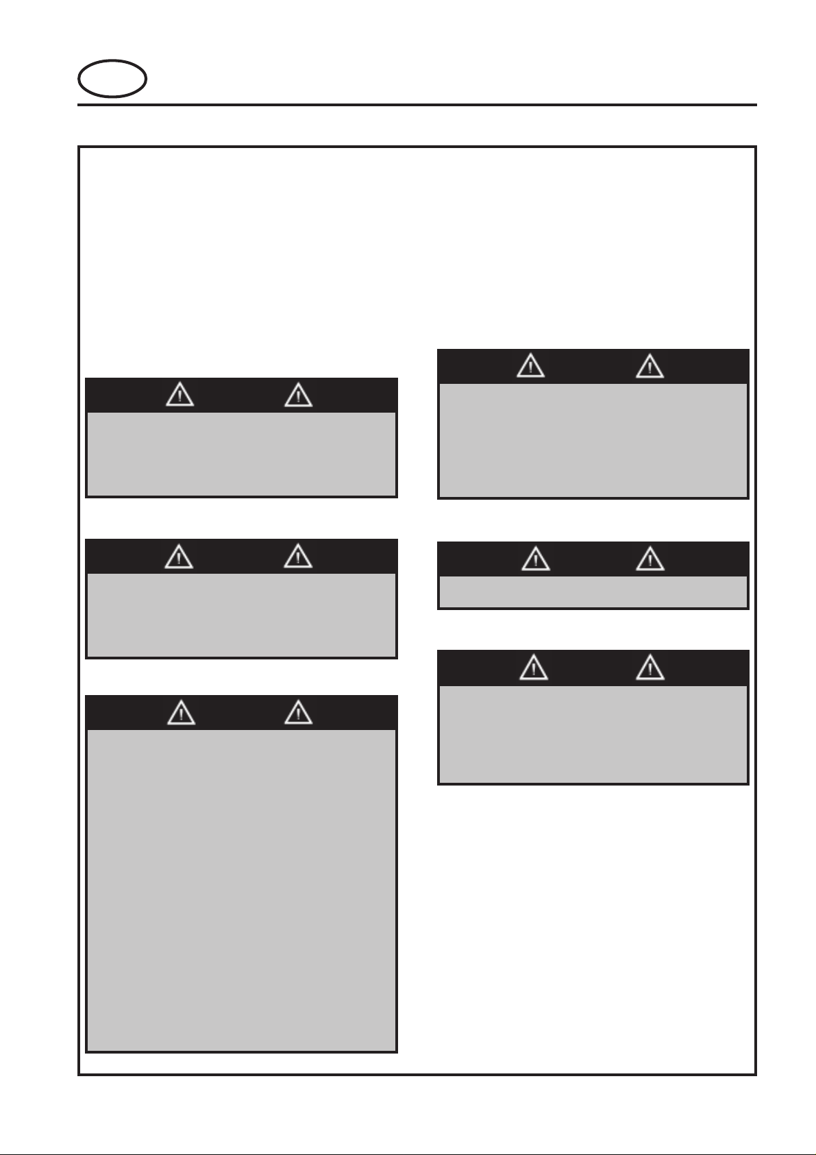
DANGER - Indicates an imminently hazardous
situation which, if not avoided, WILL result in death
or serious injury.
WARNING - Indicates a potentially hazardous
situation which, if not avoided, COULD result in
death or serious injury.
CAUTION - Indicates a potentially hazardous
situation which, if not avoided, MAY result in minor
or moderate injury and property damage. It may
also be used to alert against unsafe practices.
WARNING
Hydraulic Fluid escaping under pressure
can penetrate skin and do serious
damage. Immediate medical assistance
must be sought.
WARNING
IMPORTANT: Transport speed is for highway
use only. Never select transport speed on grass
areas or uneven or unsurfaced roads or tracks.
The operating Instructions for the Cutting Units are
contained in a separate Publication .
WARNING
California Proposition 65
Engine Exhaust, some of its constituents,
and certain vehicle components contain
or emit chemicals known to the state of
California to cause cancer and birth
defects or other
WARNING
Batteries produce explosive gases and
contain corrosive acid and supply levels
of electrical current high enough to cause
burns.
WARNING
Before releasing transport latches it is
important that all cutting units are fully
raised.
1. Park the machine on level ground.
2. With the engine running at operating
speed raise the cutting units to their
maximum position by operating lift
levers whilst seated in the driving
position.
3. Disengage drives, stop the engine and
make sure all moving parts are
stationary. Apply brakes and remove
the starter key.
DO NOT USE ON SLOPES GREATER THAN 15°
WARNING
Battery posts, terminals and related
accessories contain lead and lead
compounds
WASH HANDS AFTER HANDLING
4. transport latches can now be released.
GB-5
Page 8

4 SPECIFICATIONS
GB
JACOBSEN G-PLEX III Series: DN & DP
SAFETY AND OPERATORS MANUAL
4.1 ENGINE SPECIFICATION
TYPE:TYPE: Kubota 15.5KW @ 3600 RPM,
3 cylinder Dioesel engine, 4
stroke, water cooled, 719cc
with 12V electric start.
Model: D722-E
Maximum Speed: 3400 RPM (No load)
Idle Speed: 1500 RPM
Oil Sump Capacity:3.2 litres
Firing Order: 1, 3, 4, 2.
Fuel: No. 2-D Diesel fuel (ASTM D975)
4.1.1 ENGINE SPECIFICATION
TYPE:TYPE: Briggs & Stratton 13.5KW @
3600 RPM, V twin gasoline
engine, 4 stroke, air cooled,
719cc with 12V electric start.
Model: Vanguard 350447 Type 1294
Maximum Speed: 3400 RPM (No load)
Idle Speed: 1500 RPM
Oil Sump Capacity:1.4 litres
Fuel: Unleaded Gasoline Minimum 85
octane
4.2 MACHINE SPECIFICATION
Frame construction:
Heavy duty fabricated steel
chassis.
Transmission:
Variable displacement
hydrostatic pump with high
speed low torque wheel motors.
Cutting unit drive:
Direct drive hydrostatic and reel
drive pumps, bi-directional
hydraulic gear motor with reel
control valve and backlap control
valve.
Speeds:
Cutting: 6 km/h
Transport: 12 kp/h
Reverse: 3 kp/h
Steering: Rear Wheel Steering. Power
Steering, 2.5 turns lock to lock
330mm dia. Steering Wheel
Ground pressure: 1.0 kg/cm
Brakes, Service: Positive hydostatic braking.
Parking: 152 mm Caliper Disk
Capacities:
Cooling System: 3.8 litres
Fuel Tank: 31 litres
Hydraulic Tank: 18.2 litres
Total System 25.7 litres
Battery: 12 volt, Type 093
Alternator Diesel 40amp
Gasoline 15amp
4.3 CUTTING UNIT
Type : Three 559mm wide steerable
floating head.
Reel: 127mm diameter, 7 / 9 / 11
knife.
Rolls: Smooth rear roll, smooth or
grooved front /rear rolls optional.
Bedknife to reel
adjustment: Opposed set screw.
Height of cut
adjustment: Micro-adjusters on front roll.
height of cut: 2.5mm to 16mm Standard blade
2mm to 16mm Tournament
blade.
4.4 DIMENSIONS
Width of cut: 1.57 metres
Overall width with reels: 1.9 metres
Overall height: 1.3 metres
Overall length with reels: 2.1 metres
Overall length with catchers: 2.5 metres
Overall weight of machine
With Reels
Diesel: 630kg
Gasoline: 574kg
Without Reels
Diesel: 535kg
Gasoline: 478kg
Wheel Track: 1.2 metres
Wheel Base: 1.3 metres
GB-6
tcudorP
IIIxelP-G021-00.01x02
SERUSSERPERYT
leehWtnorF leehWraeR
eziSeryTepyTeryTerusserPeryTeziSeryTepyTeryTerusserPeryT
rp2htoomSnatiTisp9rab26.0
021-00.01x02
rp2htoomSnatiTisp9rab26.0
Page 9
GB
JACOBSEN G-PLEX III Series: DN & DP
SAFETY AND OPERATORS MANUAL
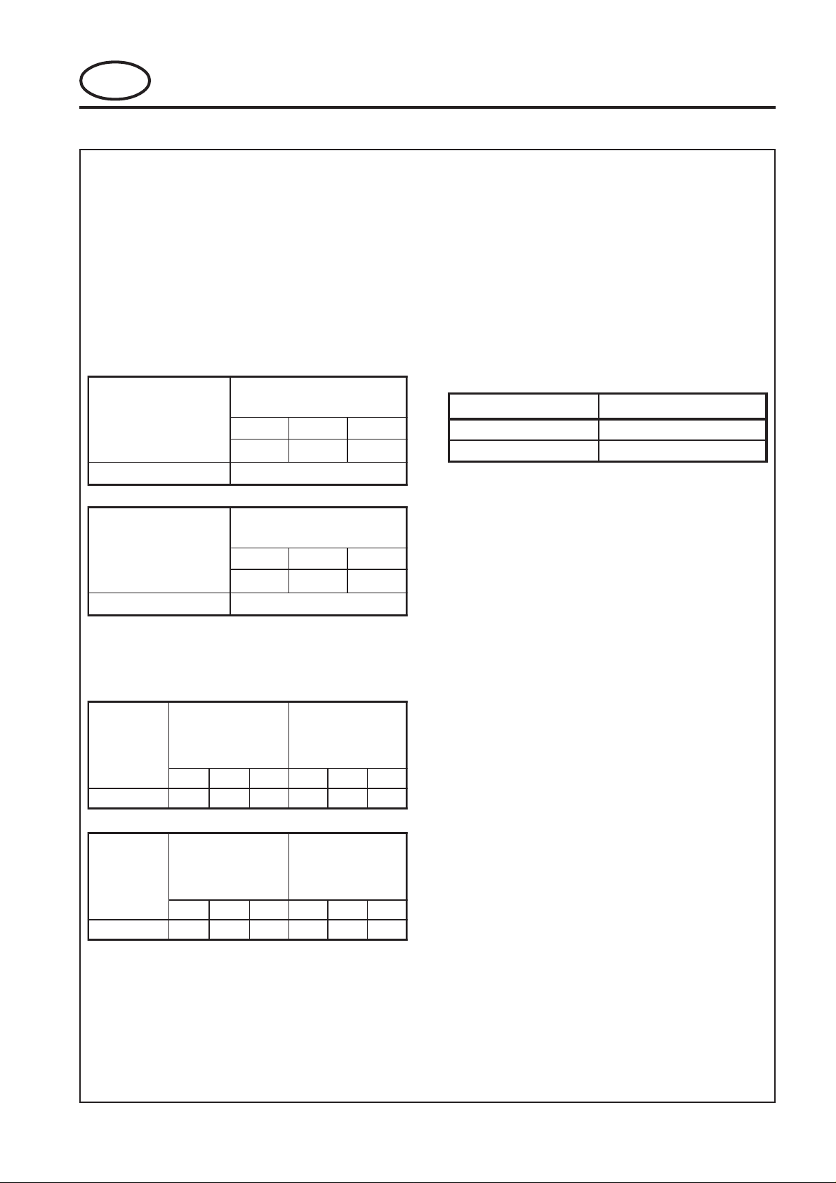
4.5 VIBRATION LEVEL
The machine was tested for whole body and hand/
arm vibration levels. The operator was seated in the
normal operating postion with both hands on the
steering mechanism. The engine was running and
the cutting device was rotating with the machine
stationary.
Standard ISO 5349: 1986 Mechanical vibration.
Guidelines for the measurement and the
assessment of human exposure to hand-transmitted
vibration.
enilosaG-IIIxelP-G
NDseireS
noitareleccAmrA/dnaH
level
eulaVtnanimoD62.1
leseiD-IIIxelP-G
PDseireS
noitareleccAmrA/dnaH
level
eulaVtnanimoD25.1
qeAXqeAYqeAZ
09.077.062.1
qeAXqeAYqeAZ
93.125.1236.0
HRroHLxaM
2
s/msnoitareleccA
HRroHLxaM
2
s/msnoitareleccA
Standard ISO 2631-1: 1985 Evaluation of human
exposure to whole body vibration -- Part 1: General
requirements.
-IIIxelP-G
enilosaG
NDseireS
ydoBelohW
noitareleccA
level
naeM80.070.065.0060.0050.0011.0
xyzxyz
noitacoLroolF
2
s/msnoitareleccA
noitacoLtaeS
2
s/msnoitareleccA
4.6 SLOPES
DO NOT USE ON SLOPES GREATER THAN 15°
The slope 15° was calculated using static stability
measurements according to the requirements of
EN 836.
4.7 RECOMMENDED LUBRICANTS
Engine oil:
Diesel: Should be to MIL-L-2104C
or to A.P.I. Classification CD
Gasoline: A.P.I. Classification SE/SF
ERUTAREPMETYTISOCSIVLIO
)F°93(C°4EVOBA03EAS
)F°93(C°4WOLEB03-W01ro03-W5EAS
Hydraulic Oil: GreensCare 68
Grease: Lithium based.
4.8 CUTTING PERFORMANCE
Cutting Frequency
7-knife reel - 7.4mm at 6km/h
9-knife reel - 5.7mm at 6km/h
11-knife reel - 4.7mm at 6km/h
-IIIxelP-G
leseiD
PDseireS
ydoBelohW
noitareleccA
level
naeM2040.05630.0402.05050.01580.07050.0
xyzxyz
noitacoLroolF
2
s/msnoitareleccA
noitacoLtaeS
2
s/msnoitareleccA
GB-7
Page 10

4 SPECIFICATIONS
JACOBSEN G-PLEX III Series: DN & DP
SAFETY AND OPERATORS MANUAL
GB
4.9 CONFORMITY CERTIFICATES
EC Declaration of Conformity • Déclaration de Conformité CE •
EG Conformiteits-Declaratie • EG-Konformitatsbescheinigung •
Certificato di Conformità CE • EF Konformitetserklæring •
EU Uppfyllandecertifikat • Ilmoitus yhdenmukaisuudesta ey:n sääntöjen kanss •
Declaración de Conformidad de la CE • Declaração de Conformidade da CE
We the undersigned • Nous, soussignés • Wij, ondergetekenden • Wir, die Unterzeichnenden • Noi sottoscritti Undertegnede •
Undertecknarna • Me allekirjoittaneet • Los abajo firmantes • Nós, abaixo assinados
Ransomes Jacobsen Limited
West Road, Ransomes Europark,
Ipswich, England, IP3 9TT
Declare that the machine Described Below • Certifions que la machine suivante • verklaren dat onderstaand beschreven machine •
erklären, dass die nachfolgend beschriebene Maschine • Dichiariamo che la macchina descritta di seguito • Erklærer, at følgende maskine •
Deklarerar att den maskin som beskrivs nedan • vahvistamme, että alla kuvattu kone • Certificamos que la máquina descrita abajo •
declaramos que a máquina a seguir descrita
Make & Type • Nom & Type • Merk & Type • Marke und Typ • Marca e tipo •
Fabrikat og type • Fabrikat & typ • Malli ja tyyppi • Marca y Tipo • Marca & Tipo .............. Jacobsen G-Plex III
Category • Modèle •Categorie • Kategorie • Categoria • Kategori • Luokka •
Categoría • Categoria ......................................................................................................... Ride on Cylinder Mower
Series • Série • Serie • Sarja .............................................................................................. DP & DN
Engine • Motor • Moteur • Motore • Moottori ....................................................................... Kubota Diesel / Briggs & Stratton Gasoline
Type • Typ • Tipo • Tyyppi ..................................................................................................Kubota D772 / Briggs & Stratton Vanguard
Net Installed Power • Puissance nette • Netto geïnstalleerd vermogen •
installierte Antriebsleistung • Potenza installata netta • Nettoeffekt installere •
Installerad nettoeffekt • Asennettu nettoteho • Potencia instalada neta •
Potência real instalada ....................................................................................................... Kubota 11.5 KW / Briggs & Stratton 11.9 KW
Cutting Width • Largeur de coupe • Maaibreedte • Schnittbreite •
Larghezza di taglio • Klippebredde • Klippbredd • Leikkuuleveys •
Anchura de corte • Potência real instalada ....................................................................... 180cm
Complies with the provisions of the following European directives and amendments and the regulations transposing it into national law •
Est conforme aux prescriptions des normes, modifications et règles européennes suivantes • voldoet aan de bepalingen van de volgende
Europese Richtlijnen en Amendementen, alsmede aan de verordeningen die deze omzetten in nationale wetgeving • den Bestimmungen der
folgenden Europa-Richtlinien einschließlich aller Änderungen und Ergänzungen sowie den Vorschriften, die diese in das nationale Recht
umsetzen, entspricht • soddisfa quanto previsto dalle seguenti direttive ed emendamenti europei e dalle normative che li riportano in legge
nazionale • Overholder bestemmelserne i følgende EF-direktiver med ændringer og i de forordninger, hvorved de omsættes til national lov •
Uppfyller kraven i följande europeiska direktiv med tillägg och regler transponerade till nationell lagstiftning • täyttää seuraavana mainittujen
Euroopan direktiivien ja muutosten ja säännösten asettamat edellyt
Machinery Safety Directive • Directive de sécurité des machines •
Richtlijn Machineveiligheid • Richtlinie zur Maschinensicherheit •
Direttiva sulla sicurezza del macchinario • Maskinsikkerhedsdirektivet •
Maskinsäkerhetsdirektiv • Koneen turvallisuutta koskeva direktiivi •
Directiva de seguridad de maquinaria • Directiva de segurança de máquinas ................98/37/EC
EMC Directive • Directive de compatibilité électromagnétique • EMC Richtlijn •
EMK-Richtlinie • Direttiva EMC • EMC-direktivet • Elektromagnetiskt kompatibilitetsdirektiv •
EMC-direktiivi • Directiva EMC .............................................................................................89/336/EC
Noise in the Environment Directive • Directiv • Richtlijn Milieulawaa •
Richtlinie zum Umgebungslärm • Direttiva sulla rumorosità nell’ambiente •
Støjemissionsdirektivet • Bullerdirektiv • Melu ympäristöä koskevassa direktiivissä •
Directiva sobre ruido en el ambiente • Directiva Ruído no Ambiente ................................ 2000/14/EC
Measured Sound Power Level • Niveau de puissance sonore assuré •
Gegarandeerd geluidsvermogenniveau • Garantierter Schallleistungspege •
Livello di potenza del suono misurato • Målt lydeffektniveau • Uppmätt ljudfraftsnivå •
Mitattu åånitehon taso • Nivel de Potencia Sonora • Nívelde intensidade de som medido .. 100 dB(A) LWA
Guaranteed Sound Power Level • Niveau de puissance sonore assuré •
Gegarandeerd geluidsvermogenniveau • Garantierter Schallleistungspege •
Livello di potenza del suono misurato • Garanteret lydeffektniveau •
Garanterad ljudtrycksnivå • Taattu äänitehon taso • Nivel Garantizado de Potencia Sonora •
Nível garantido de intensidade sonora .............................................................................. 105 dB(A) LWA
GB-8
Page 11

4 SPECIFICATIONS
JACOBSEN G-PLEX III Series: DN & DP
SAFETY AND OPERATORS MANUAL
GB
Conformity Assessment Procedure • Procédure de conformité•évaluation • Conformiteitsbeoordelingsprocedur • Verfahren zur Beurteilung
der Konformität • Procedura di valutazione conformità • Procedure for overensstemmelsesvurdering • Procedur för utvärderande av
uppfyllande • Yhdenmukaisuuden arviointiproseduuri • Procedimiento de evaluación de conformidad • Processo de avaliação de
conformidade
Annex VI, Part 1• Annexe VI, Part 1 • Bijlage VI, Part 1 • Anlage VI, Part 1 • Allegato VI, Part 1 • Anneks VI, Part 1 • Annex VI,
Part 1 • Liite VI, Part 1 • Anexo VI, Part 1 • Anexo VI, Part 1
U.K. Notifiable Body (No.1088) • Institut britannique à notifie(No.1088)r • Britse onderzoeksinstantie (No.1088) • in GB zu informierende
Institution (No.1088) • Ente notificabile Gran Bretagna • (No.1088) • Organ, som skal underrettes (No.1088) • Brittiskt meddelandeorgan
(No.1088) • Ison-Britannian ilmoitusosapuoli (No.1088) • Cuerpo notificable en el Reino Unido (No.1088) • Entidade a notificar no Reino
Unido ( No.1088)
Sound Research Laboratories Limited
Holbrook House, Little Waldingfield
Sudbury, Suffolk CO10 0TH
Operator Ear Noise Level • Bruit au niveau des oreilles de l’opérateur •
Geluidsniveau op oorhoogte bediener • Schallpegel am Ohr des Fahrers •
Livello rumorosità orecchio operatore • Støjniveau ved betjening •
Bullernivå vid operatörens öron • Käyttäjän korvaan kohdistuva äänitaso •
Nivel de ruido en el oido del operari • Nível de ruído nos ouvidos do operador ............... 82.6 dB(A)Leq (98/37/EC)
Complies with the following harmonised standard or technical provisions • est conforme aux normes harmonisées • Voldoet aan de
volgende geharmoniseerde norm of technische bepalingen • Diese Maschine entspricht den folgenden harmonisierten Normen oder
technischen Bestimmungen • Rispetta il seguente standard armonizzato o requisiti tecnici • Overholder følgende harmoniserede
standardbestemmelser eller tekniske bestemmelser • Uppfyller följande harmoniserade standard eller tekniska definitione • täyttää
seuraavat harmonisoidut standardit tai tekniset edellytykset • Cumple con los siguientes estándares de hramonización o provisiones
técnicas • Está em conformidade com a norma harmonizada ou com as provisões técnicas seguintes
Machinery Safety • Sécurité des machines • Machineveiligheid •
Maschinensicherhei • Sicurezza del macchinario • Maskinsikkerhed •
Maskinsäkerhet • Koneen turvallisuus • Seguridad de maquinaria •
Segurança de máquinas ....................................................................................................EN836
Hand Transmitted Vibration • Vibrations transmises aux mains •
Via de hand overgebrachte trilling • Auf das Hand-Arm-System übertragene Schwingungen •
Vibrazione trasmessa dalla mano • Håndoverført vibration •
Handöverförda vibrationer • Käsivälitteinen tärinä • Vibración transmitida a la mano •
Vibrações transmitidas através das mãos........................................................................ ISO5349: 1986
Whole Body Vibration • Vibrations du corps entier • Trilling hele lichaam •
Auf den gesamten Körper übertragene Schwingungen • Vibrazione di tutto il corpo •
Vibration i hele kroppen • Hel kropps vibrationer • Koko kehoon kohdistuva tärinä •
Vibración de todo el cuerpo • Vibração em todo o corpo ................................................. ISO2631-1: 1985
Keeper of Technical File, Place & Date of Declaration • Lieu & Date de déclaration • Plaats & datum verklaringsaflegging • Ort und Datum
dieser Erklärung • Luogo e data della dichiarazione • Sted og dato for erklæringen • Plats & datum för deklaration • Lausunnon paikka ja
päivämäärä • Lugar y fecha de la declaración • Local e data da declaração
Technical Director
Ransomes Jacobsen Limited
Central Avenue, Ransomes Europark,
Ipswich, England, IP3 9QG
01.09.2004
T Lansdell
Technical Director
Certificate Number • Numéro du certificat • Certificaatnummer • Zertifikat Nummer •
Numero certificato • Certifikatnummer • Certifikat nummer • Sertifikaattinumero •
Número de certificado • Número do Certificado 4126000 (Rev.2)
GB-9
Page 12
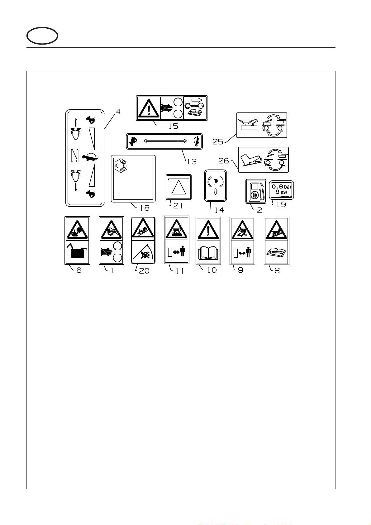
5 DECALS
05
GB
5.1 SAFETY DECALS
L
JACOBSEN G-PLEX III Series: DN & DP
SAFETY AND OPERATORS MANUAL
WA
105
SAFETY & INSTRUCTION DECALS
1 A903488 Do Not Open or Remove
Safety Shields While the Engine is
Running.
2 838419 Diesel Fuel Only
4 840065 Speed Control
dB
13 838363 Engine Speed Control.
14 838367 Parking Brake ‘P’.
15 840748 Keep hands out of moving
parts. Shut of engine and remove key
before servicing equipment.
6 A911410 Danger of Explosion if the
Battery Terminals are Short Circuited.
8 A903493 Avoid Fluid Escaping
Under Pressure. Consult Technical
Manual for Service Procedures.
9 A903489 Keep a Safe Distance
from the Machine.
10 A903491 Read Operator's Manual.
11 A903492 Stay Clear of Hot
Surfaces.
GB-10
18 A903477 Maximum Sound Power
Level.
19 A903950 Tyre Pressure.
20 A911416 Maximum permitable
working slope.
21 A911430 Jacking Point
25 A293952 Paddle Control. Mow/
Raise Cutting Units.
26 A923953 Footswitch Control. Mow/
Raise Cutting Units.
Page 13
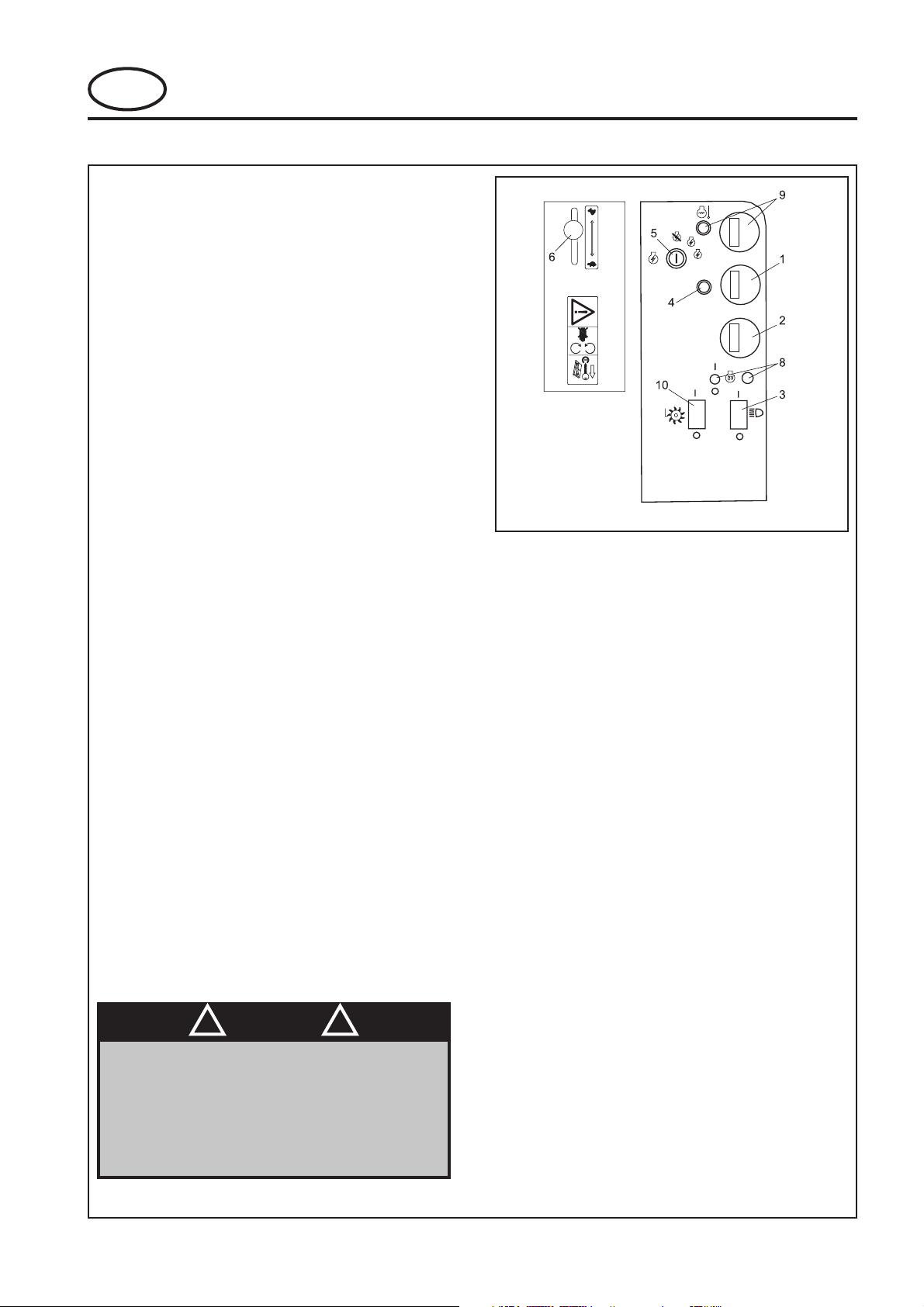
6 CONTROLS
GB
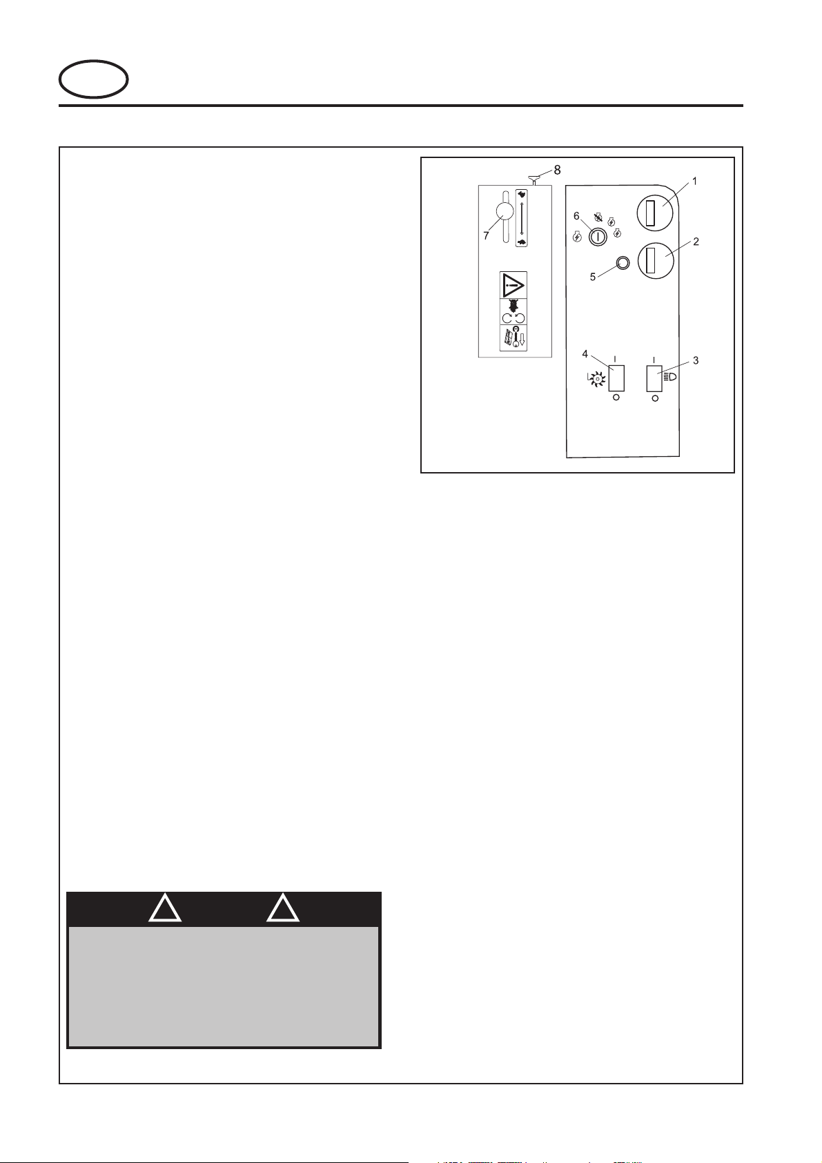
6.1 HAND CONTROLS - DIESEL
1. Voltmeter
2. Hour Meter
3. Headlight Switch
4. Engine Oil Warning Light
5. Ignition Switch
6. Throttle
8. Pre–Heat Switch and Glow Plug Light
9. Temperature Gauge And Warning Light
10. Reel Enable Switch
Voltmeter
indicates battery condition.
Headlight Switch
turns the headlights on and off.
JACOBSEN G-PLEX III Series: DN & DP
SAFETY AND OPERATORS MANUAL
Engine Oil Warning Light
will come on when the engine oil pressure is too low
for operation.
Ignition Switch
has four positions:
OFF - prevents all electrical functions from
operating. Switch must be in the OFF position to
remove the key.
ON - for normal operation.
START - engages the starter. Release the key after
engine starts (the switch automatically returns to
ON).
ACC. - has no function on this unit.
NOTE
If the engine fails to start, or if it “dies” for any
reason, the ignition switch must be returned to
the OFF position before restarting is attempted.
This feature prevents damage to the starter and
flywheel teeth that can occur if the starter is
engaged while the engine is running. Wait 30
seconds before restarting engine.
Throttle
Push all the way forward for normal engine operating
speed, and all the way back for idle.
Hour Meter
records the number of hours the engine has run. Use
the hour meter to manage a good scheduled
maintenance program (refer to the Maintenance
Guide).
Temperature Gauge and Warning Light
gauge indicates coolant temperature and light warns
of overheat situation.
Reel Enable Switch
This switch must be in the on position (1) in order for
the reels to rotate. The switch must be in the off
position (0) for the unit to be started.
Preheat Switch & Glow Plug Light
With the ignition switch in the 'ON' position, hold the
preheat switch in the 'ON' position until the indicator
lamp go's out. The engine can now be started.
WARNING
! !
When the ignition is switched on, if the
units are in the lowered position they will
raise. It should be ensured that
operators/bystanders are clear of all
moving parts before the ignition switch is
switched on.
GB-11
Page 14
GB
6.1.1 HAND CONTROLS - GASOLINE
1. Voltmeter
2. Hour Meter
3. Headlight Switch
4. Reel Enable Switch
5. Engine Oil Warning Light
6. Ignition Switch
7. Throttle
8. Choke
Voltmeter
indicates battery condition.
Headlight Switch
turns the headlights on and off.
Engine Oil Warning Light
will come on when the engine oil pressure is too low
for operation.
JACOBSEN G-PLEX III Series: DN & DP
SAFETY AND OPERATORS MANUAL
Ignition Switch
has four positions:
OFF - prevents all electrical functions from
operating. Switch must be in the OFF position to
remove the key.
ON - for normal operation.
START - engages the starter. Release the key after
engine starts (the switch automatically returns to
ON).
ACC. - has no function on this unit.
NOTE
If the engine fails to start, or if it “dies” for any
reason, the ignition switch must be returned to
the OFF position before restarting is attempted.
This feature prevents damage to the starter and
flywheel teeth that can occur if the starter is
engaged while the engine is running. Wait 30
seconds before restarting engine.
Throttle
Push all the way forward for normal engine operating
speed, and all the way back for idle.
Hour Meter
records the number of hours the engine has run. Use
the hour meter to manage a good scheduled
maintenance program (refer to the Maintenance
Guide).
Reel Enable Switch
This switch must be in the on position (1) in order for
the reels to rotate. The switch must be in the off
position (0) for the unit to be started.
Choke
Pull choke control out to start engine. In warm
weather temperatures, move choke control in slowly
over several seconds, in cold weather allow engine
to run smoothly before each change.
WARNING
! !
When the ignition is switched on, if the
units are in the lowered position they will
raise. It should be ensured that
operators/bystanders are clear of all
moving parts before the ignition switch is
switched on.
GB-12
Page 15
6 CONTROLS
GB
6.2 CONTROL PEDALS
The Direction/Speed Pedal controls speed and
direction. Depress front of pedal to go forward,
depress back of pedal to go backward. Increased
movement of the pedal will increase speed. To slow
and stop the unit, release the pedal completely.
Proper braking is provided by hydrostatic pressure. If
more braking is required, press on the brake pedal.
WARNING
! !
DO NOT attempt to force the direction control
pedal to the neutral (stop) position or to
change directions before coming to a
complete stop. Abrupt stops or changes in
direction may cause injury.
NOTE
To reduce fatigue during normal forward operation,
the operator’s heel should rest on the floorboard
next to the pedal (not on the lower part of the
pedal).
JACOBSEN G-PLEX III Series: DN & DP
SAFETY AND OPERATORS MANUAL
2
1
1. Direction/Speed Pedal
2. Brake Pedal
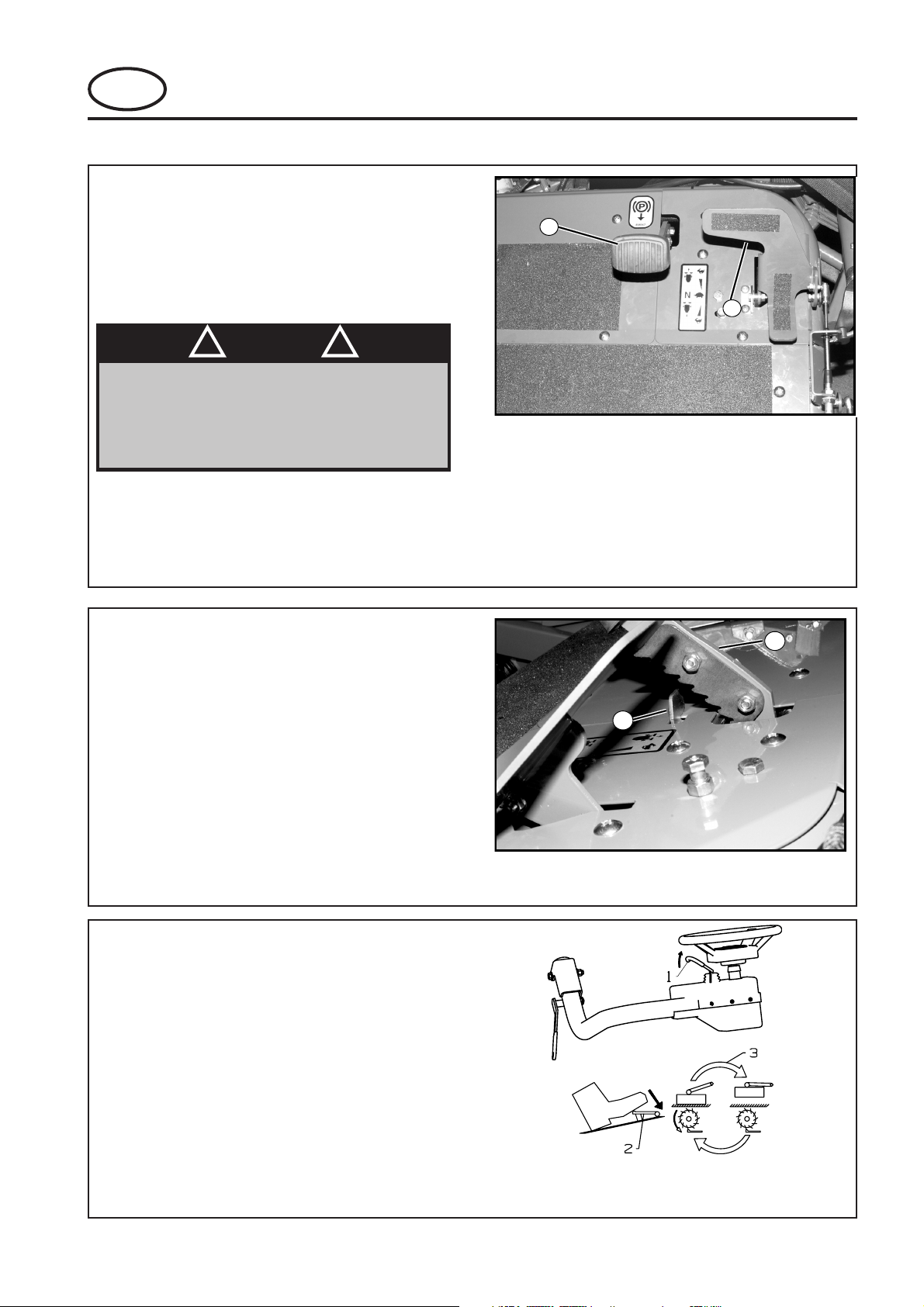
6.3 PARKING BRAKE PEDAL
The Parking Brake can be engaged by depressing
the brake pedal until the unit is at a complete stop.
Once the unit is stoped, push the parking brake
latch foward to hold the brake pedal. Disengage the
parking brake by depressing and releasing the brake
pedal.
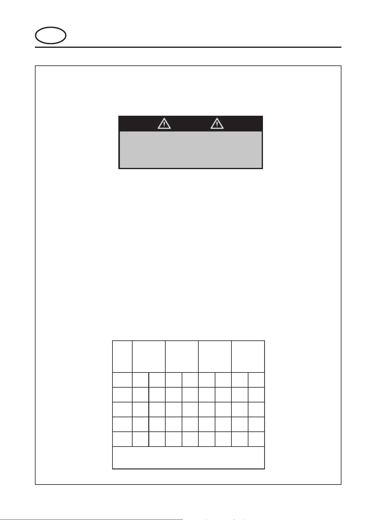
6.4 PADDLE/FOOTSWITCH MOW/LIFT
The Mow/Lift Paddle/Footswitch lowers and raises
the cutting heads.
To Lower the Heads: Depress the footswitch or
operate the paddle. If reel enable switch is on, reel
rotation starts when the heads are lowered.
To Raise the Heads: Depress the footswitch or
operate the paddle. Reel rotation stops when the
heads are raised.
1
2
1. Brake Pedal
2. Park Brake Latch
1. Paddle Control (Mow/Raise)
2. Footswitch Control (Mow/Raise)
3. Illustration of Paddle/Footswitch Operati
GB-13
Page 16

7 OPERATION
JACOBSEN G-PLEX III Series: DN & DP
SAFETY AND OPERATORS MANUAL
GB
7.1 DAILY INSPECTION
CAUTION
The daily inspection should be performed
only when the engine is off and all fluids
are cold. Lower implements to the
ground, engage parking brake, stop
engine and remove ignition key.
1. Perform a visual inspection of the entire unit, look for signs of wear, loose hardwear and missing or
damaged components. Check for fuel and oil leaks to ensure connections are tight and hoses and
tubes are in good condition.
2. Check the fuel supply, radiator coolant level, crankcase oil level and air cleaner. All fluids must be at
the full mark with the engine cold.
3. Make sure all cutting units are adjusted to the same height of cut.
4. Check all tyres for proper inflation.
5. Test the operator presence and safety interlock system.
GB-14
Page 17
7 OPERATION
JACOBSEN G-PLEX III Series: DN & DP
SAFETY AND OPERATORS MANUAL
GB
7.2 OPERATOR PRESENCE AND SAFETY INTERLOCK SYSTEM
1. The operator presence & safety interlock system prevents the engine from starting unless the parking
brake is engaged, the mowing device is off and the operator is in the seat. The system also stops the
engine if the operator leaves the seat with the mowing device engaged or the parking brake disengaged.
WARNING
Never operate the equipment with the
operator presence & safety interlock
system disengaged or malfunctioning. Do
not disconnect or bypass any switch.
2. Perform each of the following tests to ensure the operator presence & safety interlock system is
functioning properly. Stop the test and have the system inspected and repaired if any of the tests fail
as listed below:
• The engine does start in test 1;
• The engine does not start during tests 2 or 3;
• The engine Stops during test 4.
3. Refer to the chart below for each test and follow the check (9) marks across the chart. Shut engine
off betwen each test.
Test1: Represents normal starting procedure. The operator is seated, parking brake is engaged, the
operators feet are off the pedals and the mower engagement device is off. The engine should start.
Test 2: The engine must not start if the mower engage device is on.
Test 3: The engine must not start if the parking brake is not applied.
Test 4: Start the engine in the normal manner, then turn mower engage device on and lift your weight
off the seat.
tseT
rotarepO
detaeS
gnikraP
ekarB
noladeP
rewoM
hctiwS
enignE
stratS
seYoNseYoNnOffOseYoN
99999999999999999999
1
99999999999999999999
2
99999999999999999999
3
999999999999999
4
tsumstinugnittucehT.taesffothgiewruoytfiL
sdnoces)7(nevesnihtiwgnitatorpots
GB-15
Page 18
7 OPERATION
JACOBSEN G-PLEX III Series: DN & DP
SAFETY AND OPERATORS MANUAL
GB
7.3 OPERATING PROCEDURE
CAUTION
To help prevent injury, always wear safety
glasses, leather work shoes or boots, a
hard hat and ear protection.
1. Under no circumstances should the engine be started without the operator seated on the tractor.
2. Do not operate tractor or attachments with loose, damaged or missing components. Whenever
possible mow when grass is dry
3. First mow in a test area to become thoroughly familiar with the operation of the tractor and control
levers.
Note: To prevent damage to the reel and bottom blade never operate the reels when they are not
cutting grass. Excessive friction and heat will develop between the bottom blade and reel
and damage the cutting edge.
4. Study the area to determine the best and safest operating procedure. Consider the height of the
grass, type of terrain, and condition of the surface. Each condition will require certain adjustments
or precautions.
5. Never direct discharge of material toward bystanders, nor allow anyone near the machine while in
operation. The owner/operator is responsible for injuries inflicted to bystanders and/or damage to their
property.
CAUTION
Pick up all debris you can find before
mowing. Enter a new area cautiously
Always operate at speeds that allow you to
have complete control of the tractor
6. Use discretion when mowing near gravel areas (roadway, parking areas, cart paths, etc.). Stones
discharged from the implement may cause serious injuries to bystanders and/or damage the
equipment.
7. Disengage the drive motors and raise the implements when crossing paths or roads. Look out for
traffic.
8. Stop and inspect the equipment for damage immediately after striking an obstruction or if the
machine begins to vibrate abnormally. Have the equipment repaired before resuming operation.
GB-16
WARNING
Before you clean, adjust, or repair this
equipment, always disengage all drives,
lower implements to the ground, engage
parking brake, stop engine and remove
key from ignition switch to prevent injuries.
Page 19
7 OPERATION
JACOBSEN G-PLEX III Series: DN & DP
SAFETY AND OPERATORS MANUAL
GB
WARNING
DO NOT USE ON SLOPES GREATER THAN 15°
9. Slow down and use extra care on hillsides. Read Section 3.7. Use caution when operating near drop
off points.
10. Never use your hands to clean cutting units. Use a brush to remove grass clippings from blades.
Blades are extremely sharp and can cause serious injuries
OPERATION OF THE MACHINE
end of the pass, raise the heads as the front
Read the Safety Instructions.
grass catchers cross the trailing edge of the
green.
7.4 MOWING PROCEDURES
NOTE: Always remove the flag and inspect the
green before mowing. Remove debris or
other objects that may damage the reels
and/or bedknives.““Operators should
practice mowing in a clear area to become
familiar with raising and lowering the
mowing heads. They should be aware that
the center cutting head raises and lowers
slightly later than the front ones, allowing
the center cut to begin and end at the
same point as the two side cuts.
Practicing will help the operator become
proficient at starting and stopping each
pass within a foot or two of the edge of the
green. Then only one final pass around the
green will be required to finish the
operation.
Several factors may determine the direction of the
mowing pattern, sand traps or other hazards near
the green, trees etc. that can restrict where turns
are made. The terrain of the green may also be a
factor, but if conditions allow, always try to mow the
green in a different direction than the last time it was
mowed.
1. Stop the unit just before reaching the
green. Make sure the reel enable switch is
in the "ON" position. Proceed onto the
green at mowing speed and lower the
mowing heads as the front grass catchers
cross the leading edge of the green. At the
2. Always make mowing passes across the
green in a straight line. DO NOT start to
make the turn for the next pass until the
rear wheel is completely off the green, this
will eliminate the possibility of the tires
tearing the turf during the turn.
3. Each successive pass should overlap the
previous one by two or three inches (51 or
76mm) (a painted mark two or three inches
(51 or 76mm) in from the outer edges of the
two front grass catchers will help align
each overlapping pass).
4. After all of the straight passes have been
made, make one final pass around the outer
edge of the green. This final pass should
always be in the opposite direction from the
last time the green was mowed.
5. With the engine stopped or the reel enable
switch in the "OFF" position, empty the
grass catchers before proceeding to the
next green.
NOTE: To avoid damage to the green, NEVER stop
the forward motion of the mower on the
green with the reels turning.
Stopping the mower on a wet green may
cause wheel indentations.
GB-17
Page 20
8 SETUP
GB
8.1 SET UP
IMPORTANT!
CALIFORNIA PUBLIC RESOURCES CODE,
SECTIONS 4428-4442, REQUIRE SPARK
ARRESTERS WHEN OPERATING ANY INTERNAL
COMBUSTION ENGINE USING HYDROCARBON
FUELS, ON FOREST-, BRUSH-, OR GRASSCOVERED LANDS.
WARNING
Setup procedures must be performed as
specified by properly trained service
personnel only.
JACOBSEN G-PLEX III Series: DN & DP
SAFETY AND OPERATORS MANUAL
Check the hydraulic system. Make sure the
connections are tight and all hoses and lines
are in good condition before pressurizing the
system. Hydraulic spstem should be allowed to
warm-up and re-check connections for leaks.
WARNING
If a leak is suspected, use a piece of
cardboard or wood, NOT your, to check
for leaks.
Hydraulic Fluid escaping under pressure
can penetrate skin and do serious
damage. Immediate medical assistance
must be sought.
Serious infection or reaction can develop
if proper medical treatment is not
administered immediately.
NOTE: Any reference to the right, left, front,
or rear of the unit will always be
determined from the operators seated
position.
GB-18
Page 21
8 SETUP
LATCH LOCKED
TO SH OULDE R BO LT
SHOWN AS
REFERE NCE O NLY
GB
8.2 MOUNTING THE CUTTING HEADS
Review the "OPERATION" section beginning on
Page 9 before mounting the cutting units.
NO T E: All Ransome Jacobsen cutting heads
are backlapped at the factory, but the
bedknife adjustment must be
performed before the unit is put into
use. Refer to the Bedknife Adjustment
Procedure as described in section 8.4
in this manual.
CAUTION
Take care when handling the cutting
heads. Injury may result from contact
with the sharp edges of the reel blades.
JACOBSEN G-PLEX III Series: DN & DP
SAFETY AND OPERATORS MANUAL
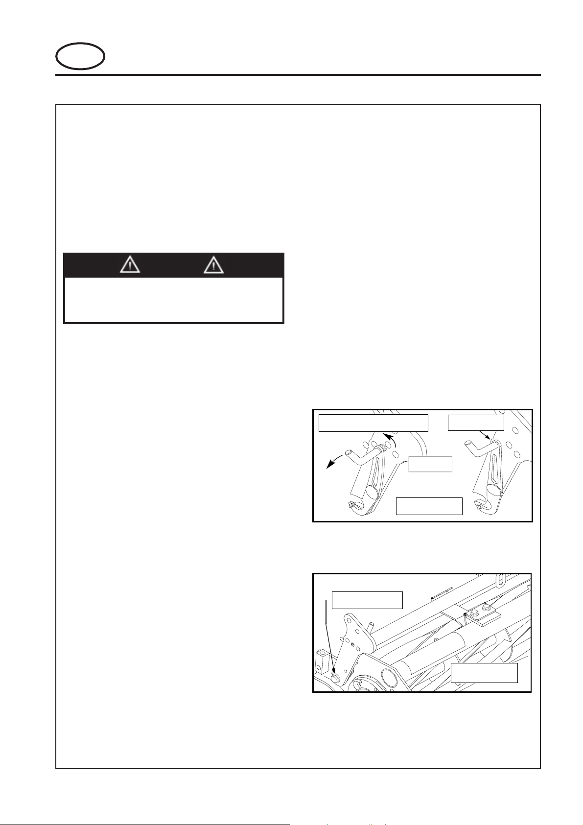
1. Cut all shipping straps holding the front
2. With the reel enable switch in the "OFF"
3. Before mounting the cutting heads, make
4. Position the cutting head at the front of
5. Pull the handle and pivot it to the rear of
pull frames in place and position the pull
frames so the upstop bumpers contact the
upstop brackets. Set cutting head drive
motors and hoses away from the lift arms.
position, lower all three cutting head lift
arms and turn off the unit and remove
ignition key.
sure the latches on the pull frames are in
the opened position (See Fig. 8.2.1).
the pull frame. Align the shoulder bolt on
each side of the cutting head, below and
slightly to the front of the slots on the pull
frame. Support the pull frame and roll the
cutting head back slightly until the
shoulder bolt (on the cutting head) is
positioned in the slot.
the head allowing the bolt head to drop
into the center hole. The latch will pivot
forward and lock under the shoulder bolt
(See Fig.8.2.2). Repeat procedure on
opposite side of the cutting head. Install
the remaining cutting heads using this
procedure.
1. P ULL HANDLE UNTI L THE HEAD
OF BO L T CLEARS THE HO L E
2
1
2. PIVOT
FORWARD
SHOWN AS
REFERENCE ONLY
Fig.8.2.1
Quick Detach Latch
8.2.2
Cutting Head Mounted to Pull Frame
LATCH IN THE
OPEN POSITION
GB-19
Page 22
8 SETUP
GB
8.3 REEL MOTOR MOUNTING
JACOBSEN G-PLEX III Series: DN & DP
SAFETY AND OPERATORS MANUAL
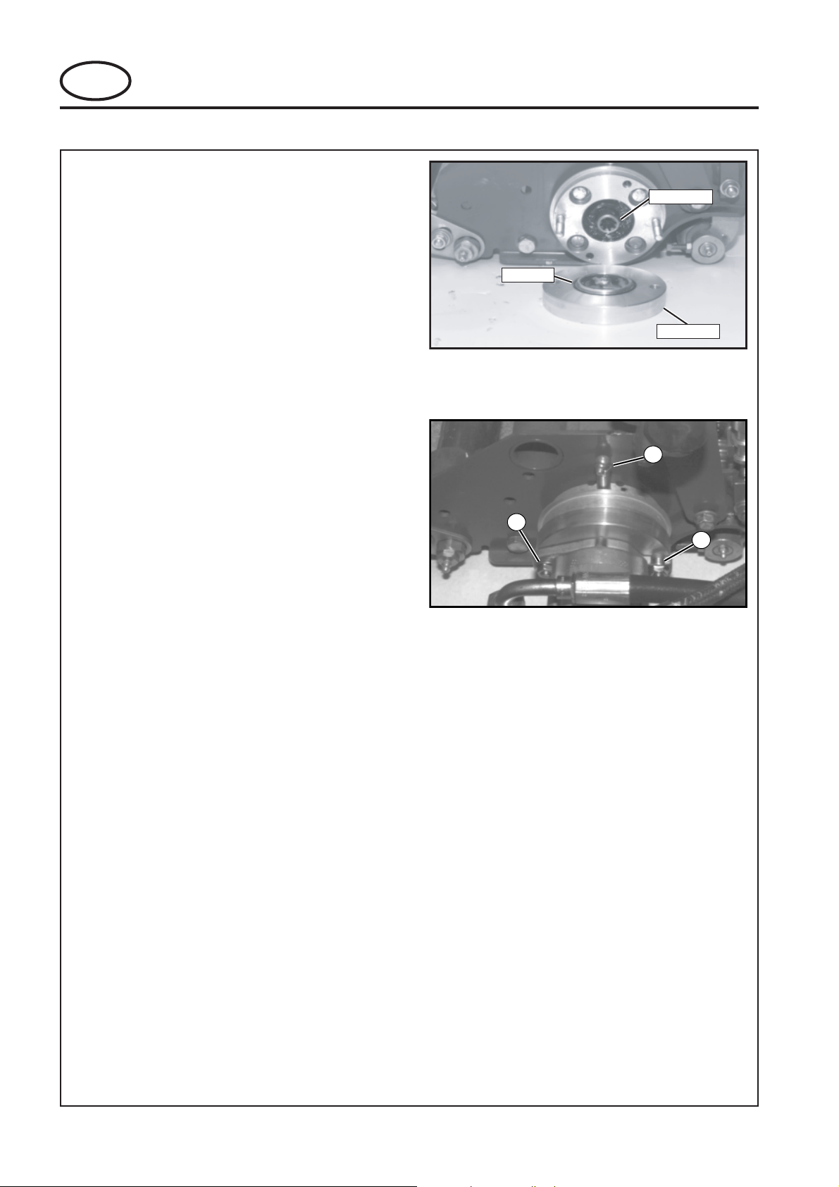
1. The cutting head motor mounting adaptor,
coupling and hardware are shipped in the
step located above the left front wheel.
Install a 1.49" i.d. x .07" (38mm x 1.7mm)
O-ring on the male side of motor adapter
plate and a 1.99" i.d. x .07" (50mm x
1.7mm) O-ring on the reel motor mount
face.
2. Remove and discard screws holding the
shipping cover to cutting head (retain the
shipping cover to protect the bearings
whenever the motor is removed from the
cutting head).
3. Install coupler on cutting head shaft (See
Fig. 8.3.1).
4. Install motor adapter plate positioning the
male face and O-ring toward the cutting
head (See Fig.8.3.1).
5. Install two (2) 5/16-18 x 1 1/2" screws
(with washer and lock washer) loosely into
the mounting holes (See Fig 8.3.2).
6. Align the splines on the motor shaft with
the coupler and slide the motor into place
rotating approximately 45_ away from the
mounting screws. With motor face against
adapter plate, rotate the motor mounting
flange into place engaging the screws into
the motor mounting flange slots. Tighten
screws to 18ft/lbs (24 N·m).
COUPLER
O-RI NG
ADAPTER
Fig.8.3.1
Motor Mounting
2
1
1
Fig.8.3.2
Motor Mounting Screws & Lubricator
7. Add lithium based lubricant to the bearing
housings at BOTH ends of the reels
(reference lubrication fitting in Figure
8.3.2). Bearings at both ends are partially
packed with lubricant at the factory, but
additional lubricant is required once
assembled. Use a pressure gun to add
lubricant until it starts to escape from the
fittings. Wipe off any excess lubricant.
NOTE: Check to MAKE SURE when the cutting
heads are lowered to the turf, they must
contact the turf evenly across the entire
length of the cutting head. If the front
cutting heads contact the level surface
unevenly, refer to the adjustment section
in the parts and maintenance manual.
GB-20
Page 23
9 ADJUSTMENTS
GB
9.1 SEAT ADJUSTMENT LEVER
Pull out on the adjustment lever located under the
left side of the seat. Slide the seat to the desired
position and release the lever (See Fig. 9.1.1).
JACOBSEN G-PLEX III Series: DN & DP
SAFETY AND OPERATORS MANUAL
Figure 9.1.1
1. Seat Adjustment Lever
9.2 CONTROL ARM ADJUSTMENT
Support the control arm to avoid a sudden drop while
adjusting its height. Loosen the Locking Lever to
allow the steering wheel and control arm to be
adjusted up or down. Tighten the locking lever when
steering wheel is at the desired position (See Fig.
9.2.1).
WARNING
DO NOT attempt to adjust the control arm
position while the machine is moving.
The operator may loose control, causing
possible injury to themselves or
bystanders.
Figure 9.2.1.
1. Control Arm Height Locking Lever.
GB-21
Page 24

9 ADJUSTMENTS
GB
9.3 BEDKNIFE ADJUSTMENT
NOTE: If the backlap valve accessory (Part
No. 2702016) is installed, the backlap valve
control lever must be in the center "neutral"
position so that the reels can be rotated
manually.
Any adjustment to the clearance between the
reel blades and the bedknife should be done at
the leading end of the reel first (the end at
which each individual blade first crosses the
bedknife). Then at the opposite end of the reel.
1. Loosen the lower adjustment screws at
each end by turning them approximately
1/4 turn counterclockwise (See Figure
9.3.2).
JACOBSEN G-PLEX III Series: DN & DP
SAFETY AND OPERATORS MANUAL
Figure 9.3.1
1. Rotate Cutting Reel with this Screw Head
2. While rotating the reel backwards, turn the
upper adjustment screws (leading end first)
until there is approximately .001, (.025mm)
clearance. After adjusting both ends,
recheck the leading end.
NOTE: Too much clearance between the bedknife
and the blades will result in poor cutting
quality. Too little clearance will cause
excessive wear to the cutting edges and
may cause damage to the bedknife, reel
blades or other components.
3. Using a wrench rotate the reel forward. The
reel must turn freely and you should just
be able to hear the reel blades making
slight contact with the bedknife (See Fig.
9.3.1.).
4. After the bedknife is properly adjusted,
tighten the lower adjustment screw at each
end.
5. Test the cutting head by holding two strips
of newsprint perpendicular to the bedknife.
Rotate the reel with a wrench. The reel
must turn freely and each blade on the reel
should cut one of the two strips of paper.
Figure 9.3.2
1. Upper Adjustment Screw
2. Lower Adjustment Screw
WARNING
To avoid the possibility of serious injury,
NEVER attempt any cutting head
adjustments while the engine is running.
WARNING
NEVER rotate the cutting reel by pushing
it with your hands or fingers. Fingers can
become caught between the reel and the
frame resulting in serious injury. Use a
rachet with a 9/16" socket on the end of
the reel shaft to rotate it during
adjustments and testing.
GB-22
Page 25

9 ADJUSTMENTS
GB
9.4 HEIGHT OF CUT
NOTE: All three cutting heads MUST be
accurately set at the same height of cut to
insure an even cut.
Bedknife adjustment must be made before
setting the height of cut.
A gauge block (Part No. 892010) is offered
separately. Order from an authorized
Textron dealer.
1. Set the height of cut on the gauge block
(Part No. 892010) by turning the wingnut
until the distance between the bottom of
the screw head and the top of the gauge
block equals the desired height of cut (See
Fig. 9.4.2).
JACOBSEN G-PLEX III Series: DN & DP
SAFETY AND OPERATORS MANUAL
Figure 9.4.1
1. Loosen Locking Nut
2. Loosen the locking nut on one of the front
roller adjusting brackets just enough to
allow adjustment (See Fig. 9.4.1).
3. Hold the gauge block (Part No. 892010)
across the bottom of both the front and
rear rollers near the roller adjustment
bracket and adjust the front roller until the
cutting edge of the bedknife comes up to
touch the bottom of the gauge screw head
(See Fig. 9.4.2).
4. Tighten the locking nut and repeat the
procedure at the other end. After
adjustment has been made at both ends,
go back and recheck both ends.
5. Make sure all three cutting heads are set
without changing the height of the gauge
screw.
Figure 9.4.2
Height of Cut Adjustment
A = Rear Roll
B = Front Roll
C = Gauge Screw Head
D = Bedknife
E = Height of Cut
GB-23
Page 26

10 LUBRICATION & MAINTENANCE
GB
10.1 LUBRICA TION AND MAINTENANCE CHART
tsriF
yliaD
8-5
sruoh
ENIGNE
leveLliOkcehC
enignEleseiDliOegnahC
enignEenilosaGliOegnahC
enignEleseiDtnemelEretliFriAkcehC
enignE
tnemelEretliFriAecalpeR
sniFgnilooCnaelC
enilosaGtnemelEretliFriAnaelC&kcehC
enignEleseiDretliFliOecalpeR
enignEenilosaGretliFliOecalpeR
leseiD-retlifleufenilnicitsalpecalpeR
leseiD-tnemelEretlifleufecalpeR
enilosaG-retlifleufecalpeR
}}
leseiD-noitanimatnocretawrofretlifleufkcehC
enignEenilosaGecnaraelCevlaVtsujdA&kcehC
52
z
z
z
JACOBSEN G-PLEX III Series: DN & DP
SAFETY AND OPERATORS MANUAL
serudecorpecnanetniampohskrowerastnioptellubetihwdnaskcehcrotarepoerastnioptellubkcalB
yrevE
sruoh
}
ylkeeW
ro
yrevE
yrevE
05tsriF
yrevE
sruoh
001
05
sruoh
sruoh
yrevE
002
052
sruoh
sruoh
}
}
}
}
} z
}
}
}
z
yevE
006
yrevE
004
rosruoh
dnE
sruoh
fo
nosaeS
}
noitceS
5.5/4.5
5.5
3.5
9.5/8.5
6.5
4.5
01.5
7.5
7.5
01.5
enignEeeS
launaM
ENIHCAM
erusserPeryTkcehC
skaeLciluardyHrofkcehC
sedalBleeR&efinkdeBkcehC
tnemtsujdAefinkdeBotleeRkcehC
leveLdiulFciluardyHkcehC
neercSrelooCliOkcehC
sniFrelooCliOnaelC
sirbeDrofyaBenignEkcehC
ssenthgiTrofstloB&stuNkcehC
ssenthgiTrofsgnittiFciluardyHkcehC
noitidnoCyrettaBkcehC
noisneTtleBkcehC
retliFciluardyHegnahC
liOciluardyHegnahC
sgniniLekarBkcehC
sgniraeBleeRtinUgnittuC
srelloRraeR&tnorFtinUgnittuC
toviPdaeHgnittuC
tnuoMdaeHgnittuC
toviPmrAtfiL
toviPlortnoCdeepS/woM
toviPladePtfiL/woM
stoviPrednilyCgnireetS
z
z
z
z
z
z
z
}
}
}
}
}
}}
}
}
esaergdesabmuihtiLahtiwgniwollofehtetacirbuL
11.5
21.5
31.5
41.5
}
}
}
}
}
}
}
}
GB-24
Page 27

10 LUBRICATION & MAINTENANCE
GB
10.2 LUBRICA TION DIAGRAM
Lubricate sparingly with a lithium based lubricant.
Excess lubricant my drop from the unit and cause turf damage.
Always wipe lubricators before and after lubrication.
JACOBSEN G-PLEX III Series: DN & DP
SAFETY AND OPERATORS MANUAL
A Cutting Unit Reel Bearings
B Cutting Unit Front & Rear Rollers
C Cutting Head Pivot
D Cutting Head Mount
E Lift Arm Pivot
F Mow / Speed Control Pivot
G Mow / Lift Pedal Pivot
H Steering Cylinder Pivots
* = Lubrication Point
GB-25
Page 28

10 LUBRICATION & MAINTENANCE
GB
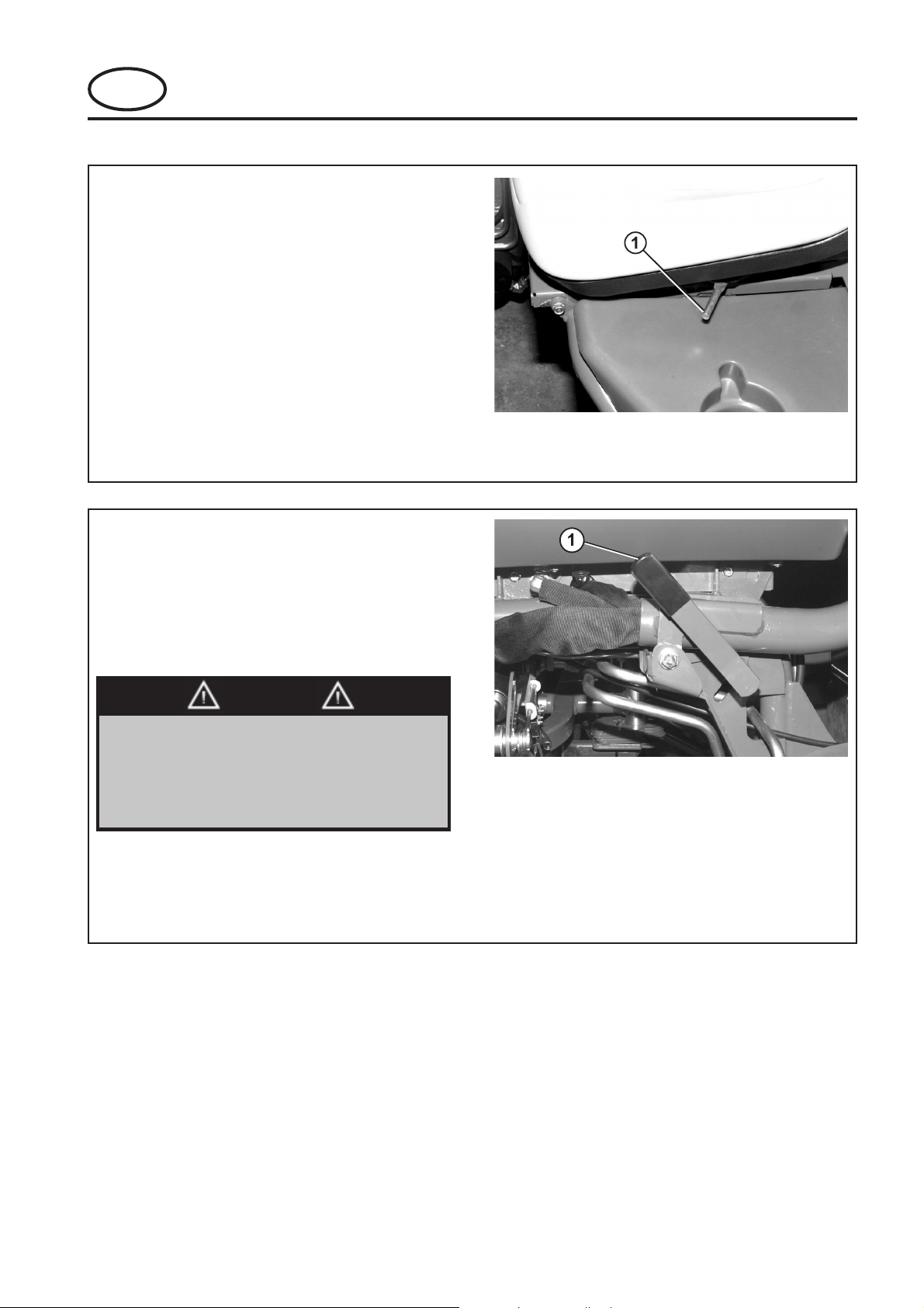
10.3 HYDRAULIC PUMP BYPASS VALVE
The Bypass Valve allows the unit to be pushed or
towed. Turn the handle on the bottom of the pump
counterclockwise (as viewed from the bottom of the
pump) to open the valve. After moving the unit, close
the valve by turning the handle clockwise (See Fig.
10.4).
NOTE: The bypass valve must be tightly closed
for normal operation or a significant loss of
speed will occur and may cause serious
damage to the hydrostatic pump.
10.4 FREE WHEELING OR TOWING UNIT
To prevent damage to the pump or wheel motors
when FREE WHEELING or TOWING:
JACOBSEN G-PLEX III Series: DN & DP
SAFETY AND OPERATORS MANUAL
Figure 10.4
1. Bypass Valve Handle
1. Engine must be OFF and cool.
2. Turn hydraulic pump bypass valve on the
bottom of the pump 180°
counterclockwise to open position (as
viewed from the bottom) (See Fig. 10.4).
3. FREE WHEEL or TOW unit slowly, below
2 mph (3.2 Km/h).
4. Before starting engine, BE SURE to turn
the pump bypass valve clockwise to fully
closed position.
NOTE: If the pump bypass valve is not completely
closed, a significant loss of speed will
occur. Operating the unit when the pump
is not completely closed, may cause
damage to the pump.“
GB-26
Page 29

10 LUBRICATION & MAINTENANCE
GB
JACOBSEN G-PLEX III Series: DN & DP
SAFETY AND OPERATORS MANUAL
10.5 FUEL RECOMMENDATIONS - DIESEL
Fuel tank should be filled to within 1/2", (13mm)
below the bottom of the filler neck. DO NOT overfill
the tank.
Use #2 diesel fuel (ASTM No. 2D) when temperature
is above 20°F (-7°C).
Use #1 diesel fuel (ASTM No. 1D) when temperature
is 20°F (-7°C) or below.
NOTE
• NEVER use No. 2D at temperatures below
20°F (-7°C) unless you are sure it has
been “winterized”. Cold temperatures will
cause fuel to thicken which may keep your
engine from running.
• If No. 1D is not available, a “winterized”
blend of No. 1D and No. 2D may be
available. This blended fuel is usually
called No. 2D also and may be used in
colder temperatures.
• If the vehicle fuel tank is being filled for the
first time or if the vehicle was allowed to
run out of fuel, it will be necessary to
bleed the air from the fuel system (refer to
“Bleeding The Fuel System" in the
Maintenance manual ).
10.51 FUEL RECOMMENDATIONS - GASOLINE
Fuel tank should be filled to within 1/2, (13mm)
below the bottom of the filler neck. DO NOT overfill
the tank.
Unleaded gasoline 87 Octane or higher
We DO NOT recommend the use of ALCOHOL
bearing fuels in any of our products. The use of
these fuels may create a potential safety hazard.
NOTE: The use of alcohol bearing fuels can cause
engine malfunction, particularly "vapor
lock" at temperatures above 50° F
(10°c C).
WARNING
Gasoline containing ALCOHOL can cause
deteration of some non-metalic materials
in the fuel system.
Fuel hoses must be inspected frequently
and replaced if excessive stiffness,
deterioration or fuel leakage is found.
Gasoline Containing ALCOHOL will
attract and hold moisture inside fuel
tanks. Moisture may cause corrosion of
metalic parts within the fuel system.
Fuel leakage from a fuel system can
occur while the system is in use, in
transit, or in starage. Such leakage can
contribute to an explosion or fire, causing
serious bodily injury or death.
GB-27
Page 30

10 LUBRICATION & MAINTENANCE
GB
10.6 AIR CLEANER - GASOLINE
Vanguard Engines: refer to the engine operator's
manual for air cleaner service and replacement.
NOTE: DO NOT use bent or dented air cleaner
housing.“DO NOT use bent or dented air
cleaner elements.
IMPORTANT!
WE RECOMMEND THAT THE FILTER ELEMENT
BE REPLACED BEFORE ENGINE PERFORMANCE
IS AFFECTED. THIS MAY OCCUR AT 250 HOURS
OF SERVICE UNDER VERY DUSTY CONDITIONS
OR AT 500 HOURS UNDER NORMAL OPERATING
CONDITIONS. WE DO NOT RECOMMEND
CLEANING THE FILTER ELEMENT BECAUSE OF
THE POSSIBILITY OF DAMAGING IT.
JACOBSEN G-PLEX III Series: DN & DP
SAFETY AND OPERATORS MANUAL
Figure 10.7
1. Pre-Cleaner
2. Air Cleaner Element
CHECKING THE ELEMENT
To check for damage, pin holes, etc. shine a light
source into the end of the element. If light CANNOT
be seen through the paper, a new element should be
installed. Likewise, if pinholes of bright light appear
in the paper, the element should be replaced (See
Fig. 10.6).
10.6.1 AIR CLEANER - DIESEL
IMPORTANT
WE RECOMMEND THAT THE FILTER ELEMENT
BE REPLACED BEFORE ENGINE
PERFORMANCE IS AFFECTED. THIS MAY
OCCUR AT 250 HOURS OF SERVICE UNDER
VERY DUSTY CONDITIONS OR AT 500 HOURS
UNDER NORMAL OPERATING CONDITIONS.
WE DO NOT RECOMMEND CLEANING THE
FILTER ELEMENT BECAUSE OF THE
POSSIBILITY OF DAMAGING IT.
CHECKING THE ELEMENT
To check for damage, pin holes, etc. shine a light
source into the end of the element. If light CANNOT
be seen through the paper, a new element should be
installed. Likewise, if pinholes of bright light appear
in the paper, the element should be replaced.
INSTALLING ELEMENT
1. Clean the dust from inside the filter
housing with a damp cloth. Make sure that
dust does not enter the engine air intake.
2. Check the soft gasket material at both
ends of the element to be sure it is not
damaged.
3
1
3
2
3. Insert the open end of the element into the
housing and press it onto the air intake
pipe at the back of the housing. Make sure
the filter element fits over the pipe snugly
and is pushed all the way on to prevent
any dust from getting past the filter.
4. Install the air cleaner cover 1 over the
element with the dust collector 2 pointing
DOWN (dust collector empties
automatically when properly installed).
Secure the cover with the two wire clips 3.
GB-28
Page 31

10 LUBRICATION & MAINTENANCE
GB
JACOBSEN G-PLEX III Series: DN & DP
SAFETY AND OPERATORS MANUAL
10.7 Tires
Keep tires properly inflated to prolong tire life. Check
inflation pressure while the tires are cool.““Use an
accurate, low pressure tire gauge.
Keep tires inflated to the air pressure specified
below.
20 x 10 - 10 Turf Tires 9 psi (0.62 bar)
10.8 ENGINE ACCESS
The rear section of the unit can be raised for better
access to the engine. Loosen the two handknobs
above the rear fork. Raise the fuel tank frame.
Support it by pivoting the rod beneath the fuel tank
down and securing it in the cup next to the fork pivot
(See Fig. 10.9).
CAUTION
Caution must be used when inflating a
low pressure tire to the recommended
pressure. Check pressure with alow
pressure tire gauge befor connecting an
air hose to a partly inflated tire.
Due to the low air volume requirements
of a small tire, over inflation may be
reached in a matter of a few seconds,
which could cause the tire to explode.
WARNING
DO NOT remove the fuel tank cap while
the tank is in the raised position.
Figure 10.8
Rear Section of Unit Raised
GB-29
Page 32

10 LUBRICATION & MAINTENANCE
GB
10.9 ENGINE OIL LEVEL - GASOLINE
Damage to engines due to improper maintenance or
use of incorrect oil quality and/or viscosity is not
covered by the engine warranty (refer to the engine
operator's manual for crankcase capacity and
recommended oil grade and weight).
Unit must be on a level surface to obtain an
accurate oil level reading.
The oil level must be kept between the two marks on
the dipstick.
NOTE: DO NOT overfill. Engine overheating
and damage may result.
JACOBSEN G-PLEX III Series: DN & DP
SAFETY AND OPERATORS MANUAL
Figure 10.9
1. Oil Filler Port
2. Dipstick“
10.9.1ENGINE OIL LEVEL - DIESEL
Damage to engines due to improper maintenance or
use of incorrect oil quality and/or viscosity is not
covered by the engine warranty (refer to the engine
operator’s manual for crankcase capacity and
recommended oil grade and weight).
Unit must be on a level surface to obtain an
accurate oil level reading.
The oil level must be kept between the two marks
on the dipstick.
NOTICE
• DO NOT overfill. Engine overheating and
damage may result.
• DO NOT use a wrench when installing the
filter, use hand pressure ONLY.
ENGINE OIL FILTER
When replacing the oil filter, apply a light film of
clean oil to the rubber seal. screw filter on until the
seal contacts the crankcase, then tighten 1/2 turn
more.
1
Figure 10.9.1
1. Dipstick
1
GB-30
Figure 10.9.2
1. Oil Filler Port
Page 33

10 LUBRICATION & MAINTENANCE
GB
10.10 BATTERY
The factory installed battery is "Low Maintenance."
Add liquid only as required.
NOTE: Keep top of battery clean and free of
corrosion by washing with a solution of
baking soda and water OR ammonia
and water. Rinse with clean water.
Batteries with heavy corrosion should
be removed and cleaned with solution.
Battery cables should be disconnected before using
a "Fast Charger.
JACOBSEN G-PLEX III Series: DN & DP
SAFETY AND OPERATORS MANUAL
WARNING
UNTRAINED / UNAUTHORIZED persons
should NEVER attempt to service or
recharge the battery in this machine.
Battery electrolyte is an acidic solution
and should be handled with care. If
electrolyte is splashed on any part of the
body, imediately flush the exposed area
with liberal amounts of water and obtain
medical aid immediately.
WARNING
DO NOT allow flames or sparks near the
battery when connecting for jump starting
or charging.
Hydrogen gas is produced during the
charging process and can be explosive.
Provide adequate ventilation to prevent
possible explosion.
GB-31
Page 34

10 LUBRICATION & MAINTENANCE
GB
10.11 JUMP STARTING
Both booster battery and discharged battery should
be treated carefully when using jumper cables.
Follow these steps exactly, take care not to cause
sparks.
1. Set the parking brake and turn off any
electrical loads.
2. Attach one end of one jumper cable to the
positive terminal of the booster battery and
the other end to the positive terminal of the
discharged battery. DO NOT permit units
to touch each other.
JACOBSEN G-PLEX III Series: DN & DP
SAFETY AND OPERATORS MANUAL
3. Attach one end of remaining cable to the
negative terminal of the booster battery
and the other end to a good ground on the
unit or engine, away from the discharged
battery. DO NOT lean over the battery
when making this connection.““Reverse
this sequence exactly when removing the
jumper cables.
NO TE : Booster batteries used for starting must
be connected with proper polarity.
10.12 CUTTING HEAD MAINTENANCE
CLEANING
The cutting heads should be washed after each days
use and dried as well as possible to prevent
rust.““All cutting surfaces (reel and bedknife) should
be given a light coating of oil or other anti-rust
compound.
LUBRICATION
The lubrication fittings at each end of both the front
and rear rollers, as well as the reel bearings at each
end should be lubricated periodically (approximately
once each week). Use only enough lubricant to keep
the bearings from drying out. Too much lubricant
may drop from mower onto turf, causing damage to
the grass (See Fig 10.12).
WARNING
DO NOT allow flames or sparks near the
battery when connecting for jump starting
or charging.
Hydrogen gas is produced during the
charging process and can be explosive.
Provide adequate ventilation to prevent
possible explosion.
Figure 10.12
1. Lubrication Fittings
GB-32
Page 35

10 LUBRICATION & MAINTENANCE
GB
10.13 HYDRAULIC SYSTEM
Reservoir Capacity 18.0L
Total System Capacity 25.5L
JACOBSEN G-PLEX III Series: DN & DP
SAFETY AND OPERATORS MANUAL
2
To check the hydraulic fluid level on units that DO
NOT have the electronic Turf Protection System
(leak detector), locate the sight glass on the tower
portion of the reservoir. Visually inspect to see if
there is 1/2" (13mm) (at ambient temperature) of
fluid visible above the lower portion of the sight
glass. If not, unscrew the reservoir cap and fill to
proper level (See Fig 10.13).
3
Figure 10.13
1. Sight Glass
2. Reservoir Cap
3. Tower
GB-33
Page 36

11 GUARANTEE / SALES & SERVICE
JACOBSEN G-PLEX III Series: DN & DP
SAFETY AND OPERATORS MANUAL
GB
GUARANTEE
We GUARANTEE that should any defect in workmanship or material occur in the
goods within TWO YEARS or two thousand hours (on models equipped with hour
meters), or whichever occurs first.
Exception to this warranty will be Aeration products, which are covered for a period
of TWO-YEARS or five hundred hours (on models equipped with hour meters) or
whichever occurs first.
We will repair, or at our option, replace the defective part without making any charge
for labour or for materials, provided that the claim under this guarantee is made
through an authorised dealer and that the defective part shall, if we so request, be
returned to us or to the dealer.
This guarantee is in addition to, and does not exclude, any condition or warranty
implied by law, except that we accept no liability in respect of used/second-hand
goods, or in respect of defects which in our opinion are in any way or to any extent
attributable to misuse, lack of reasonable care or ordinary wear and tear, or to the
fitting of spares, replacements, or extra components which are not supplied or
approved by us for the purpose. The use of non-recommended oil or lubricant
nullifies the guarantee.
Damage through transport or normal wear does not come under the guarantee.
The warranty is extended to the original purchaser only and is not transferable to
subsequent owners. The warranty period begins on the date the product is delivered
to the end user (customer), unless otherwise agreed with the manufacturer. At the
end of the first year the owner must have the product serviced by an authorised
dealer to be eligible for the second year of warranty coverage.
SALES & SERVICE
A network of authorised Sales and Service dealers has been established and these
details are available from your supplier.
When service attention, or spares, are required for the machine, within or after the
guarantee period your supplier or any authorised dealer should be contacted.
Always quote the registered number of the machine.
If any damage is apparent when delivery is made, report the details at once to the
supplier of the machine.
KEY NUMBERS. It is recommended that all key numbers are noted here:
Starter Switch :- ...............
Diesel tank :- ...............
It is also recommended that the machine and engine numbers are recorded.
The machine serial number is located on the registration plate and the engine serial
number can be found under the exhaust maifold above the starter motor.
Machine Number :- ...............
Engine Number :- ...............
GB-34
Page 37

GB
JACOBSEN G-PLEX III Series: DN & DP
SAFETY AND OPERATORS MANUAL
NOTES
GB-35
Page 38

GB
JACOBSEN G-PLEX III Series: DN & DP
SAFETY AND OPERATORS MANUAL
GB-36
Page 39

1 TABLE DES MATIERES
TABLES DES MA TIERES P AG E
2 INTRODUCTION ......................................................................................................... 2
2.1 IMPORTANT .................................................................................................. 2
2.2 IDENTIFICATION DU PRODUIT....................................................................... 2
3 CONSIGNES DE SECURITE ........................................................................................ 3
3.1 NOTICE DE FONCTIONNEMENT .................................................................... 3
3.2 VIGNETTES DE SECURITE ............................................................................. 3
3.3 DEMARRAGE DU MOTEUR ............................................................................ 3
3.4 CONDUITE DE LA MACHINE ......................................................................... 3
3.5 TRANSPORT ................................................................................................. 3
3.6 A VANT DE QUITTER LE POSTE DE CONDUITE..............................................4
3.7 PENTES ......................................................................................................... 4
3.8 BLOCAGE DES CYLINDRES DE COUPE ......................................................... 4
3.9 REGLAGES, GRAISSAGE ET MAINTENANCE ............................................... 4
4 SPECIFICA TIONS ...................................................................................................... 6
4.1 SPECIFICATIONS DU MOTEUR ..................................................................... 6
4.2 SPECIFICA TIONS DE LA MACHINE............................................................... 6
4.3 UNITE DE COUPE ........................................................................................... 6
4.4 DIMENSIONS ................................................................................................. 6
4.5 NIVEAU DE VIBRATION ................................................................................. 7
4.6 PENTES ......................................................................................................... 7
4.7 LUBRIFIANTS RECOMMANDES .................................................................... 7
4.8 PERFORMANCE DE COUPE ........................................................................... 7
4.9 CERTIFICA TS DE CONFORMITE ................................................................... 8
JACOBSEN G-PLEX III Série : DN & DP
MANUEL DE L’OPERATEUR ET DE SECURITE
5 VIGNETTES .............................................................................................................. 10
5.1 VIGNETTES DE SECURITE ............................................................................ 10
6 COMMANDES .......................................................................................................... 11
6.1 COMMANDES MANUELLES - DIESEL .......................................................... 11
6.1.1 COMMANDES MANUELLES - ESSENCE ...................................................... 12
6.2 PEDALE DE COMMANDE ............................................................................. 13
6.3 PEDALE DU FREIN DE STA TIONNEMENT ...................................................... 13
6.4 PEDALE DE COMMANDE DE FLOTT AGE/TONTE/LEVAGE........................... 13
7 FONCTIONNEMENT .................................................................................................. 14
7.1 CONTROLE QUOTIDIEN ............................................................................... 14
7.2 SYSTEME DE PRESENCE DE L’OPERA TEUR ET
CIRCUIT D’INTERVERROUILLAGE ............................................................... 15
7.3 FONCTIONNEMENT ...................................................................................... 16
7.4 PROCEDURES DE TONTE ............................................................................. 17
8 MISE AU POINT ........................................................................................................ 18
8.1 MISE AU POINT............................................................................................ 18
8.2 MONTAGE DES TETES DE COUPE................................................................ 19
8.3 FIXA TION DU MOTEUR DES TOURETS ......................................................... 20
9 REGLAGES ............................................................................................................... 21
9.1 LEVIER DE REGLAGE DU SIEGE ................................................................... 21
9.2 REGLAGE DE LA BIELLETTE DE COMMANDE ............................................. 21
9.3 REGLAGE DE LA CONTRE-LAME ................................................................ 22
9.4 HAUTEUR DE COUPE .................................................................................... 23
10 GRAISSAGE ET MAINTENANCE ............................................................................... 24
10.1 TABLEAU DE GRAISSAGE ET DE MAINTENANCE........................................ 24
10.2 SCHEMA DE GRAISSAGE ............................................................................ 25
10.3 SOUPAPE DE DERIV ATION DE POMPE HYDRAULIQUE................................. 26
10.4 DEPLACEMENT EN ROUE LIBRE OU REMORQUAGE DE LA MACHINE ........ 26
10.5 RECOMMANDATIONS POUR LES CARBURANTS - DIESEL ......................... 27
10.5.1 RECOMMANDA TIONS POUR LES CARBURANTS - ESSENCE ...................... 27
10.6 EPURATEUR D’AIR - ESSENCE ..................................................................... 28
10.6.1 EPURATEUR D’AIR - DIESEL......................................................................... 28
10.7 PNEUS .......................................................................................................... 29
10.8 ACCES AU MOTEUR .................................................................................... 29
10.9 NIVEAU D’HUILE DU MOTEUR - ESSENCE .................................................... 30
10.9.1 NIVEAU D’HUILE DU MOTEUR - DIESEL ....................................................... 30
10.10 BATTERIE ..................................................................................................... 31
10.11 DEMARRAGE PAR CABLES VOLANTS........................................................ 32
10.12 ENTRETIEN DES TETES DE COUPE ............................................................... 32
10.13 CIRCUIT HYDRAULIQUE............................................................................... 33
1 1 GARANTIE / VENTES & SERVICE APRES-VENTE ..................................................... 34
FR-1
Page 40

2 INTRODUCTION
JACOBSEN G-PLEX III Série : DN & DP
MANUEL DE L’OPERATEUR ET DE SECURITE
2.1 IMPORTANT
IMPORTANT : Il s’agit d’une machine de précision et le service qu’elle rend dépend de la manière dont elle
est exploitée et entretenue.
Ce MANUEL DE L'OPERATEUR ET DE SECURITE doit être considéré comme faisant partie de la machine.
Il est conseillé aux fournisseurs de machines neuves et de machines d’occasion de conserver une preuve
documentaire comme quoi ce manuel a été fourni avec la machine.
Cette machine est exclusivement destinée aux opérations de tonte habituelle. Tout autre usage est
considéré comme contraire à l’utilisation prévue. Le respect et la stricte observation des conditions
d’exploitation, d’entretien et de réparation définies par le fabricant constituent des éléments essentiels à
l’usage prévu.
Avant de tenter d’utiliser cette machine, TOUS les opérateurs DOIVENT prendre connaissance de ce
manuel et se familiariser entièrement avec les instructions de sécurité, les commandes, le graissage et la
maintenance.
Observez tout le temps les réglementations sur la prévention des accidents, toutes les autres
réglementations généralement admises sur la sécurité et la santé professionnelle ainsi que toutes les
réglementations du code de la route.
Toute modification arbitraire effectuée sur cette machine peut décharger le fabricant de sa responsabilité visà-vis des dommages ou des accidents qui en résultent.
2.2 IDENTIFICATION DU PRODUIT
A Nom de la machine
B Numéro de série
C Date de fabrication
D Poids
E Puissance moteur
FR-2
Page 41

3 CONSIGNES DE SECURITE
Ce symbole représente les consignes de sécurité
principales à suivre. Lorsque vous voyez ce
symbole, soyez conscient des risques de
blessures, lisez attentivement sa consigne et
prévenez les autres opérateurs.
3.1 NOTICE DE FONCTIONNEMENT
• Ce manuel doit être lu et assimilé.
• Les personnes ne connaissant parfaitement
les commandes et les consignes de sécurité
ne sont pas autorisées à conduire la
machine.
• N’autorisez jamais l’utilisation de cette
machine par des enfants ou personnes
n’ayant pas bien pris connaissance de ces
consignes. Il se peut que des réglementations
locales limitent l’âge de l’opérateur.
3.2 VIGNETTES DE SECURITE
• Il est essentiel que les vignettes de sécurité
soient lisibles. Si tel n’est pas le cas ou si
certaines vignettes manquent, celles-ci
doivent être remplacées. Si une pièce de la
machine est remplacée, sa vignette de
sécurité doit être remplacée et placée sur la
pièce de rechange. Vous pouvez vous
procurer ce genre de vignettes auprès du
Service de Pièces Rechange de Ransomes.
3.3 DEMARRAGE DU MOTEUR
• Avant de mettre le moteur en route vérifiez
que les freins sont serrés, qu'il est au point
mort, que les protections sont en place et en
bon état et que personne ne se trouve à
proximité de la machine.
• Ne faites pas tourner le moteur dans un local
fermé et mal ventilé.
3.4 CONDUITE DE LA MACHINE
• Avant d'utiliser la machine, vérifiez que toutes
les pièces sont en bon état en faisant
particulièrement attention aux freins, aux
pneus, à la direction et aux lames de coupe.
• Remplacez les silencieux défectueux, et ne
tondez que lorsqu’il fait jour ou sous une
lumière artificielle adéquate.
• Respectez toujours les règles du Code de la
Route aussi bien sur les routes qu'en dehors.
Soyez toujours vigilant.
• Arrêtez la rotation des lames avant de
traverser des surfaces non herbues.
JACOBSEN G-PLEX III Série : DN & DP
MANUEL DE L’OPERATEUR ET DE SECURITE
• Rappelez- vous que certaines personnes sont
sourdes on aveugles et que les enfants et
animaux sont impredicables.
• Ne roulez jamais trop vite pour qu'un arrêt
d'urgence reste toujours possible.
• Avant de tondre, enlevez du terrain les objets
pouvant se transformer en projectile et vous
blesser ou blesser des passants.
• Faites particulièrement attention en marche
arrière. NE TRANSPORTEZ JAMAIS de
passagers.
• N’oubliez jamais que l’opérateur ou
l’utilisateur est responsable des accidents
dont peuvent être victimes d’autres personnes
ou leurs biens, ainsi que des risques
auxquels ces personnes ou leurs biens
peuvent être exposés.
• Lorsque la machine doit être garée,
entreposée ou laissée sans surveillance,
abaissez les dispositifs de coupe, sauf si les
blocages de transport sont utilisés.
• Lorsque vous tondez, portez toujours des
chaussures appropriées et un pantalon long.
N’utilisez pas le matériel alors que vous vous
trouvez pieds nus ou en sandales ouvertes.
• Vérifiez souvent le dispositif de collecte des
déchets d’herbe pour vous assurer qu’il n’est
ni usé ni endommagé. Quand vous heurtez un
objet qui n’aurait pas dû se trouver sur la
pelouse, examinez la machine pour vous
assurer qu’elle n’est pas endommagée, et
réparez tous les dégâts éventuels avant de
redémarrer et d’utiliser le matériel.
• Si la machine se met à vibrer excessivement,
essayez d'en trouver immédiatement la
cause.
3.5 TRANSPORT
• Vérifiez que les unités de coupe soient bien
verrouillées. Ne roulez jamais quand les
cylindres de coupe en rotation.
• Conduisez en tenant toujours compte de l'état
des surfaces et déclivités.
• Une décélération ou freinage brusques
risquent de soulever les roues arrière.
• Notez que la stabilité de l'arrière de la
machine diminue au fur et à mesure de la
consommation en carburant.
3.6 AVANT DE QUITTER LE POSTE DE
CONDUITE
• Garez la machine sur un sol plat.
• Arrêtez le moteur et vérifiez que les organes
mobiles soient bien arrêtés. Serrez les freins
et débrayez. Retirez la clé de contact.
FR-3
Page 42

3 CONSIGNES DE SECURITE
JACOBSEN G-PLEX III Série : DN & DP
MANUEL DE L’OPERATEUR ET DE SECURITE
3.7 PENTES
ATTENTION AUX PENTES
• Les déclivités locales affectent les pentes.
Evitez les surfaces qui risquent de faire
glisser la machine.
• Roulez lentement sur les pentes et dans les
virages serrés.
• Une décélération ou un freinage brusques
risquent de soulever les roues arrière.
Souvenez-vous qu’une pente «sans risque»
n’existe pas.
• Il faut faire très attention quand vous
conduisez sur des pentes.
NE PAS UTILISER SUR DES PENTES
SUPERIEURES A 15°
IMPORTANT : Pour travailler sur les pentes,
utilisez le stabilisateur quand son réglage est au
maximum (+).
3.8 BLOCAGE DES CYLINDRES DE COUPE
• Arrêtez le moteur et assurez-vous que toutes
les pièces mobiles soient arrêtées.
• Serrez les freins et débrayez.
• Faites très attention lorsque vous débloquez
les cylindres. Eloignez-vous des lames.
Veillez à ce que l'énergie résiduelle ne
provoque pas la rotation soudaine des lames
dès qu'elles sont débloquées.
• Eloignez toute personne des unités de coupe
car la rotation d'un cylindre peut entraîner la
rotation des autres.
3.9 REGLAGES, GRAISSAGE ET
MAINTENANCE
• Arrêtez le moteur et assurez-vous que les
pièces mobiles soient arrêtées. Serrez les
freins et débrayez.
• Serrez les freins et désembrayez l’ensemble
des entraînements.
• Lisez les consignes de sécurité.
• N’utilisez que les pièce des rechange du
fabricant d’origine.
• Lors du réglage des cylindres de coupe,
veillez à ce que les mains ou pieds ne soient
pas happés quand les cylindres tournent.
• Veillez à ce que personne ne touche les
cylindres de coupe car la rotation d'un
cylindre peut entraîner la rotation des autres.
• Pour réduire le risque d’incendie, ne laissez ni
herbe, ni feuilles, ni excès de graisse
s’accumuler sur le moteur, le silencieux ou la
batterie.
• Pour des raisons de sécurité, remplacez les
pièces usées ou endommagées.
• Quand il faut travailler sous des composants
ou machine levés, veillez à utiliser un support
stable.
• Ne démontez pas la machine sans avoir
auparavant fait chuter les tensions résiduelles
qui risquent d'activer les pièces.
• Ne modifiez pas la vitesse du moteur au-delà
de la vitesse maximale spécifiée dans les
données techniques du moteur. Ne modifiez
pas les réglages du régulateur du moteur et
n’emballez pas le moteur. En faisant tourner
le moteur à une vitesse excessive, vous
augmentez les risques de blessures.
• Pour faire le plein de carburant, ARRETEZ LE
MOTEUR, NE FUMEZ PAS. Remplissez
toujours le réservoir de carburant avant de
démarrer le moteur. Ne faites jamais de
remplissage d’appoint alors que le moteur
tourne.
• Utilisez un entonnoir quand vous remplissez
avec un bidon.
• Le remplissage du réservoir de carburant ne
doit pas dépasser le point de repère du goulot
de remplissage.
• Remettez soigneusement en place tous les
bouchons du réservoir et des récipients de
carburant.
• Conservez le carburant dans des récipients
spécialement prévus à cet effet.
• Le remplissage de carburant doit toujours se
faire à l’extérieur. Ne fumez pas pendant cette
opération.
• Si de l’essence se renverse, n’essayez pas
de démarrer le moteur ; éloignez la machine
de la zone où l’essence s’est renversée, et
évitez de créer des sources inflammables tant
que les vapeurs d’essence ne se sont pas
dissipées.
• Laissez le moteur refroidir avant de ranger la
machine dans un local quelconque.
• Lorsqu’il reste de l’essence dans le réservoir,
n’entreposez jamais le matériel dans un
bâtiment où les vapeurs risquent d’entrer en
contact avec une flamme ou une étincelle
nue.
• S’il s’avère nécessaire de vidanger le réservoir
de carburant, faites-le dehors.
• Ne renversez pas de carburant sur des
composants chauds.
• Lors de l'entretien de la batterie, NE FUMEZ
PAS, et éloignez-vous des flammes nues.
• Ne placez jamais d'objets métalliques sur les
terminaux.
FR-4
Page 43

3 CONSIGNES DE SECURITE
JACOBSEN G-PLEX III Série : DN & DP
MANUEL DE L’OPERATEUR ET DE SECURITE
DANGER - Indique un danger immédiat avec
RISQUE de mort ou de blessures graves.
AVERTISSEMENT - Indique un danger avec
RISQUE EVENTUEL de mort ou de blessures
graves.
ATTENTION - Indique un danger possible avec
RISQUE EVENTUEL de légères blessures ou
d'endommagement de la machine ou des biens. Il
sert également à signaler des opérations
dangereuses.
AVERTISSEMENT
Le fluide hydraulique s’échappant sous
pression risque de pénétrer la peau et de
provoquer de graves blessures. En cas de
contact, appeler immédiatement un docteur.
AVERTISSEMENT
IMPORTANT : Les vitesses de conduite ne
s'appliquent qu'aux routes principales.
N'utilisez jamais ces vitesses pour rouler sur
des terrains herbeux, irréguliers ou sur des
routes non macadamisées.
La notice de fonctionnement des unités de coupe
est livrée séparément.
AVERTISSEMENT
Avertissement – Proposition 65
La Californie tient à informer que les fumées
moteur de cette machine, ou de certains de
ses composants, renferment des produits
chimiques susceptibles de provoquer des
cancers, déformités natales et séquelles.
Les batteries produisent des gas explosifs,
renferment de l’acide corrosif et génèrent
un courant électrique assez élevé risquant
de causer des brûlures.
AVERTISSEMENT
Les unités de coupe doivent être totalement
relevées avant de desserrer les verrous de
transport.
1. Garer la machine sur une surface nivelée.
2. Alors que le moteur tourne au régime de
service, lever les unités de coupe au
maximum avec le levier de levage tout
en restant assis en position de conduite.
3. Désembrayer les entraînements, arrêter
le moteur et veiller à ce que les pièces
mobiles soient toutes arrêtées. Serrer
les freins et retirer la clé de contact.
AVERTISSEMENT
INTERDIT SUR LES PENTES DE PLUS DE 15°.
AVERTISSEMENT
Les bornes de la batterie et accessoires
connexes contiennent du plomb et des
composés de plomb.
SE LAVER LES MAINS APRES TOUTE
MANIPULATION
4. Desserrer les verrous de transport.
FR-5
Page 44

4 SPECIFICATIONS
JACOBSEN G-PLEX III Série : DN & DP
MANUEL DE L’OPERATEUR ET DE SECURITE
4.1 SPECIFICATIONS DU MOTEUR
TYPE : Kubota 15,5 KW @ 3 600 tr/min,
moteur diesel 3 cylindres, 4
temps, refroidi par eau, 719 cc,
démarrage électrique 12 V.
Modèle : D722-E
Vitesse maxi : 3 400 tr/min (à vide)
Vitesse à vide : 1 500 tr/min
Volume du carter
d’huile : 3,2 litres
Ordre d’allumage : 1, 3, 4, 2.
Carburant : Diesel No. 2-D (ASTM
D975)
4.1.1 SPECIFICATIONS DU MOTEUR
TYPE : Briggs & Stratton 13,5 KW @ 3
600 tr/min, bimoteur essence V,
4 temps, refroidi par air, 719 cc,
démarrage électrique 12 V.
Modèle : Vanguard 350447 Type 1294
Vitesse maxi : 3 400 tr/min (à vide)
Vitesse à vide : 1 500 tr/min
Volume du carter
d’huile : 1,4 litre
Carburant : Essence sans plomb.
Indice mini d'octane
85.
4. 2 SPECIFICATIONS DE LA MACHINE
Structure du
châssis : Acier pour services intensifs.
Transmission : Pompe hydrostatique
volumétrique variable et moteurs
de roues à bas couple ultra
rapide.
Volumes :
Circuit de
refroidissement : 3,8 litres
Réservoir
carburant : 31 litres
Réservoir
hydraulique : 18,2 litres
Circuit complet : 25,7 litres
Batterie : 12 V, Type 093
Alternateur Diesel 40 Amp
Essence 15 Amp
4.3 UNITE DE COUPE
Type : Trois têtes flottantes dirigeables de
559 mm de largeur.
Tourets : Ø 127 mm, 7 / 9 / 11 lames.
Rouleaux : Rouleau arrière lisse, rouleaux
avant/arrière lisses ou rainurés
(option).
Réglage de
la contrelame
Par rapport au
touret : Vis de réglage opposée.
Réglage de la
hauteur de
coupe : Microrégleurs sur rouleau avant.
Hauteur de
coupe : Lames standard : 2,5 - 16 mm
Lames de tournament : 2 - 16 mm.
Entraînement des
unités de coupe : Entraînement hydrostatique
direct et pompes d’entraînement
à tourets, motoréducteur
hydraulique bidirectionnel avec
soupape de commande des
tourets et soupape de
commande de meulage.
Vitesses :
Tonte : 6 km/h
Transport : 12 km/h
Marche arrière : 3 km/h
Direction : Roues arrière. Direction
assistée, braquage : 2,5 tours
Ø 330 mm. Roues directrices.
Pression au sol : 1 kg/cm
Freins, Service : Freinage hydrostatique positif
Stationnement : Disque avec étrier 152 mm
uDnoitacifitnedI
tiudorP
IIIxelP-G021-00.01x02
suenPepyTnoisserPsuenPepyTnoisserP
tnavA erèirrA
rp2htoomSnatiTisp9rab26.0
4.4 DIMENSIONS
Largeur de coupe : 1,57 m
Largeur hors tout
avec tourets : 1,9 m
Hauteur hors tout : 1,3 m
Longueur hors tout
avec tourets : 2,1 m
Longueur hors tout
avec collecteurs : 2,5 m
Poids hors tout de la machine
Avec tourets
Diesel : 630 kg
Essence : 574 kg
Sans tourets
Diesel : 535 kg
Essence : 478 kg
Voie : 1,2 m
Empattement : 1,3 m
suenP
021-00.01x02
rp2htoomSnatiTisp9rab26.0
FR-6
Page 45

4 SPECIFICATIONS
JACOBSEN G-PLEX III Série : DN & DP
MANUEL DE L’OPERATEUR ET DE SECURITE
4.5 NIVEAU DE VIBRATION
La machine a été testée pour des niveaux de
vibration sur tout le corps et les mains / les
biellettes. L’opérateur était assis en position
d’utilisation normale, les deux mains sur le volant.
Le moteur tournait et le dispositif de coupe était en
rotation avec la machine immobile.
Norme ISO 5349 : Vibrations mécaniques 1986.
Guides pour mesurer et évaluer l’exposition du corps
et des mains aux vibrations.
ecnessE-IIIxelP-G
NDeiréS
sednoitarélécca'duaeviN
sniam/sarb
etnanimodruelaV62,1
leseiD-IIIxelP-G
PDeiréS
sednoitarélécca'duaeviN
sniam/sarb
etnanimodruelaV25,1
2
)
s/m(
qeAXqeAYqeAZ
09,077,062,1
2
)
s/m(
qeAXqeAYqeAZ
93,125,1236,0
DuoGselamixamsnoitaréléccA
DuoGselamixamsnoitaréléccA
4.6 PENTES
N’UTILISEZ PAS LA MACHINE SUR DES PENTES
SUPERIEURES A 15°.
La pente de 15° a été calculée en utilisant des
mesures de stabilité statique conformes aux
prescriptions de l’EN 836.
4.7 LUBRIFIANTS RECOMMANDES
Huile moteur : Diesel : Doit être conforme à
MIL-L-2104C ou à A.P.I.
Classification CD.
Essence : A.P.I. Classification
SE/SF.
Huile hydraulique : GreensCare 68.
4.8 PERFORMANCE DE COUPE
Touret à 7 lames - 7,4 mm à 6 km/h
Touret à 9 lames - 5,7 mm à 6 km/h
Touret à 11 lames - 4,7 mm à 6 km/h
Norme ISO 2631-1 : Evaluation des vibrations au
niveau du corps entier 1985 - Section 1 :
Prescriptions générales.
-IIIxelP-G
ecnessE
NDeiréS
noitaréléccA
uaevinua
sprocud
leseiD
PDeiréS
sprocud
xyzxyz
enneyoM80,070,065,0060,0050,0011,0
-IIIxelP-G
noitaréléccA
uaevinua
xyzxyz
enneyoM2040,05630,0402,05050,01580,07050,0
rehcnalpuduaeviN
2
s/mnoitaréléccA
rehcnalpuduaeviN
2
s/mnoitaréléccA
egèisuduaeviN
2
s/mnoitaréléccA
egèisuduaeviN
2
s/mnoitaréléccA
FR-7
Page 46

4 SPECIFICATIONS
JACOBSEN G-PLEX III Série : DN & DP
MANUEL DE L’OPERATEUR ET DE SECURITE
4.9 CERTIFICATS DE CONFORMITE
EC Declaration of Conformity • Déclaration de Conformité CE •
EG Conformiteits-Declaratie • EG-Konformitatsbescheinigung •
Certificato di Conformità CE • EF Konformitetserklæring •
EU Uppfyllandecertifikat • Ilmoitus yhdenmukaisuudesta ey:n sääntöjen kanss •
Declaración de Conformidad de la CE • Declaração de Conformidade da CE
We the undersigned • Nous, soussignés • Wij, ondergetekenden • Wir, die Unterzeichnenden • Noi sottoscritti Undertegnede •
Undertecknarna • Me allekirjoittaneet • Los abajo firmantes • Nós, abaixo assinados
Ransomes Jacobsen Limited
West Road, Ransomes Europark,
Ipswich, England, IP3 9TT
Declare that the machine Described Below • Certifions que la machine suivante • verklaren dat onderstaand beschreven machine •
erklären, dass die nachfolgend beschriebene Maschine • Dichiariamo che la macchina descritta di seguito • Erklærer, at følgende maskine •
Deklarerar att den maskin som beskrivs nedan • vahvistamme, että alla kuvattu kone • Certificamos que la máquina descrita abajo •
declaramos que a máquina a seguir descrita
Make & Type • Nom & Type • Merk & Type • Marke und Typ • Marca e tipo •
Fabrikat og type • Fabrikat & typ • Malli ja tyyppi • Marca y Tipo • Marca & Tipo .............. Jacobsen G-Plex III
Category • Modèle •Categorie • Kategorie • Categoria • Kategori • Luokka •
Categoría • Categoria ......................................................................................................... Ride on Cylinder Mower
Series • Série • Serie • Sarja .............................................................................................. DP & DN
Engine • Motor • Moteur • Motore • Moottori ....................................................................... Kubota Diesel / Briggs & Stratton Gasoline
Type • Typ • Tipo • Tyyppi ..................................................................................................Kubota D772 / Briggs & Stratton Vanguard
Net Installed Power • Puissance nette • Netto geïnstalleerd vermogen •
installierte Antriebsleistung • Potenza installata netta • Nettoeffekt installere •
Installerad nettoeffekt • Asennettu nettoteho • Potencia instalada neta •
Potência real instalada ....................................................................................................... Kubota 11.5 KW / Briggs & Stratton 11.9 KW
Cutting Width • Largeur de coupe • Maaibreedte • Schnittbreite •
Larghezza di taglio • Klippebredde • Klippbredd • Leikkuuleveys •
Anchura de corte • Potência real instalada ....................................................................... 180cm
Complies with the provisions of the following European directives and amendments and the regulations transposing it into national law •
Est conforme aux prescriptions des normes, modifications et règles européennes suivantes • voldoet aan de bepalingen van de volgende
Europese Richtlijnen en Amendementen, alsmede aan de verordeningen die deze omzetten in nationale wetgeving • den Bestimmungen der
folgenden Europa-Richtlinien einschließlich aller Änderungen und Ergänzungen sowie den Vorschriften, die diese in das nationale Recht
umsetzen, entspricht • soddisfa quanto previsto dalle seguenti direttive ed emendamenti europei e dalle normative che li riportano in legge
nazionale • Overholder bestemmelserne i følgende EF-direktiver med ændringer og i de forordninger, hvorved de omsættes til national lov •
Uppfyller kraven i följande europeiska direktiv med tillägg och regler transponerade till nationell lagstiftning • täyttää seuraavana mainittujen
Euroopan direktiivien ja muutosten ja säännösten asettamat edellyt
Machinery Safety Directive • Directive de sécurité des machines •
Richtlijn Machineveiligheid • Richtlinie zur Maschinensicherheit •
Direttiva sulla sicurezza del macchinario • Maskinsikkerhedsdirektivet •
Maskinsäkerhetsdirektiv • Koneen turvallisuutta koskeva direktiivi •
Directiva de seguridad de maquinaria • Directiva de segurança de máquinas ................98/37/EC
EMC Directive • Directive de compatibilité électromagnétique • EMC Richtlijn •
EMK-Richtlinie • Direttiva EMC • EMC-direktivet • Elektromagnetiskt kompatibilitetsdirektiv •
EMC-direktiivi • Directiva EMC .............................................................................................89/336/EC
Noise in the Environment Directive • Directiv • Richtlijn Milieulawaa •
Richtlinie zum Umgebungslärm • Direttiva sulla rumorosità nell’ambiente •
Støjemissionsdirektivet • Bullerdirektiv • Melu ympäristöä koskevassa direktiivissä •
Directiva sobre ruido en el ambiente • Directiva Ruído no Ambiente ................................ 2000/14/EC
Measured Sound Power Level • Niveau de puissance sonore assuré •
Gegarandeerd geluidsvermogenniveau • Garantierter Schallleistungspege •
Livello di potenza del suono misurato • Målt lydeffektniveau • Uppmätt ljudfraftsnivå •
Mitattu åånitehon taso • Nivel de Potencia Sonora • Nívelde intensidade de som medido .. 100 dB(A) LWA
Guaranteed Sound Power Level • Niveau de puissance sonore assuré •
Gegarandeerd geluidsvermogenniveau • Garantierter Schallleistungspege •
Livello di potenza del suono misurato • Garanteret lydeffektniveau •
Garanterad ljudtrycksnivå • Taattu äänitehon taso • Nivel Garantizado de Potencia Sonora •
Nível garantido de intensidade sonora .............................................................................. 105 dB(A) LWA
FR-8
Page 47

4 SPECIFICATIONS
JACOBSEN G-PLEX III Série : DN & DP
MANUEL DE L’OPERATEUR ET DE SECURITE
Conformity Assessment Procedure • Procédure de conformité•évaluation • Conformiteitsbeoordelingsprocedur • Verfahren zur Beurteilung
der Konformität • Procedura di valutazione conformità • Procedure for overensstemmelsesvurdering • Procedur för utvärderande av
uppfyllande • Yhdenmukaisuuden arviointiproseduuri • Procedimiento de evaluación de conformidad • Processo de avaliação de
conformidade
Annex VI, Part 1• Annexe VI, Part 1 • Bijlage VI, Part 1 • Anlage VI, Part 1 • Allegato VI, Part 1 • Anneks VI, Part 1 • Annex VI,
Part 1 • Liite VI, Part 1 • Anexo VI, Part 1 • Anexo VI, Part 1
U.K. Notifiable Body (No.1088) • Institut britannique à notifie(No.1088)r • Britse onderzoeksinstantie (No.1088) • in GB zu informierende
Institution (No.1088) • Ente notificabile Gran Bretagna • (No.1088) • Organ, som skal underrettes (No.1088) • Brittiskt meddelandeorgan
(No.1088) • Ison-Britannian ilmoitusosapuoli (No.1088) • Cuerpo notificable en el Reino Unido (No.1088) • Entidade a notificar no Reino
Unido ( No.1088)
Sound Research Laboratories Limited
Holbrook House, Little Waldingfield
Sudbury, Suffolk CO10 0TH
Operator Ear Noise Level • Bruit au niveau des oreilles de l’opérateur •
Geluidsniveau op oorhoogte bediener • Schallpegel am Ohr des Fahrers •
Livello rumorosità orecchio operatore • Støjniveau ved betjening •
Bullernivå vid operatörens öron • Käyttäjän korvaan kohdistuva äänitaso •
Nivel de ruido en el oido del operari • Nível de ruído nos ouvidos do operador ............... 82.6 dB(A)Leq (98/37/EC)
Complies with the following harmonised standard or technical provisions • est conforme aux normes harmonisées • Voldoet aan de
volgende geharmoniseerde norm of technische bepalingen • Diese Maschine entspricht den folgenden harmonisierten Normen oder
technischen Bestimmungen • Rispetta il seguente standard armonizzato o requisiti tecnici • Overholder følgende harmoniserede
standardbestemmelser eller tekniske bestemmelser • Uppfyller följande harmoniserade standard eller tekniska definitione • täyttää
seuraavat harmonisoidut standardit tai tekniset edellytykset • Cumple con los siguientes estándares de hramonización o provisiones
técnicas • Está em conformidade com a norma harmonizada ou com as provisões técnicas seguintes
Machinery Safety • Sécurité des machines • Machineveiligheid •
Maschinensicherhei • Sicurezza del macchinario • Maskinsikkerhed •
Maskinsäkerhet • Koneen turvallisuus • Seguridad de maquinaria •
Segurança de máquinas ....................................................................................................EN836
Hand Transmitted Vibration • Vibrations transmises aux mains •
Via de hand overgebrachte trilling • Auf das Hand-Arm-System übertragene Schwingungen •
Vibrazione trasmessa dalla mano • Håndoverført vibration •
Handöverförda vibrationer • Käsivälitteinen tärinä • Vibración transmitida a la mano •
Vibrações transmitidas através das mãos........................................................................ ISO5349: 1986
Whole Body Vibration • Vibrations du corps entier • Trilling hele lichaam •
Auf den gesamten Körper übertragene Schwingungen • Vibrazione di tutto il corpo •
Vibration i hele kroppen • Hel kropps vibrationer • Koko kehoon kohdistuva tärinä •
Vibración de todo el cuerpo • Vibração em todo o corpo ................................................. ISO2631-1: 1985
Keeper of Technical File, Place & Date of Declaration • Lieu & Date de déclaration • Plaats & datum verklaringsaflegging • Ort und Datum
dieser Erklärung • Luogo e data della dichiarazione • Sted og dato for erklæringen • Plats & datum för deklaration • Lausunnon paikka ja
päivämäärä • Lugar y fecha de la declaración • Local e data da declaração
Technical Director
Ransomes Jacobsen Limited
Central Avenue, Ransomes Europark,
Ipswich, England, IP3 9QG
01.09.2004
T Lansdell
Technical Director
Certificate Number • Numéro du certificat • Certificaatnummer • Zertifikat Nummer •
Numero certificato • Certifikatnummer • Certifikat nummer • Sertifikaattinumero •
Número de certificado • Número do Certificado 4126000 (Rev.2)
FR-9
Page 48

5 VIGNETTES
05
5.1 VIGNETTES DE SECURITE
L
JACOBSEN G-PLEX III Série : DN & DP
MANUEL DE L’OPERATEUR ET DE SECURITE
WA
105
VIGNETTES DE SECURITE ET D’INSTRUCTION
1 A903488 Interdiction d’ouvrir ou d’enlever
les protections pendant que le
moteur tourne.
2 838419 Carburant Diesel seulement.
4 840065 Régulateur de vitesse.
6 A911410 Danger ! Risque d’explosion
quand les bornes de la batterie
ne sont pas court-circuitées.
8 A903493 Danger ! Fluide sous pression.
Voir la Notice Technique pour
l’entretien.
9 A903489 Attention à la machine.
dB
10 A903491 Lire le Manuel de l'Opérateur.
13 838363 Régulateur de vitesse moteur.
14 838367 Frein de stationnement ‘P’.
15 840748 Ne pas toucher aux pièces
mobiles. Arrêter le moteur et
retirer la clé de contact avant
toute intervention sur
l’équipement.
18 A903477 Pression acoustique maximale.
19 A903950 Pression des pneus.
20 A911416 Pente de travail maximum.
21 A911430 Point de levage
25 A293952 Commande de Flottage/Tonte/
Levage des unités de coupe.
11 A903492 Ne pas toucher aux surfaces
chaudes.
FR-10
26 A923953 Pédale de commande. Tonte/
Levage des unités de coupe.
Page 49

6 COMMANDES
6.1 COMMANDES MANUELLES - DIESEL
1. Voltmètre
2. Horamètre
3. Interrupteur de phares
4. Témoin lumineux d’huile moteur
5. Contact de démarrage
6. Papillon des gaz
8. Interrupteur de préchauffage et témoin
lumineux de bougie de préchauffage
9. Jauge de température et témoin lumineux
10. Interrupteur de mise en marche des
tourets
Voltmètre
Il indique l’état de la batterie.
Horamètre
Il enregistre le nombre d’heures de service du
moteur. Vous pouvez l’utiliser pour obtenir un
programme de maintenance adéquat (à cet effet,
reportez-vous au Manuel de Maintenance).
Interrupteur de phares
Il permet d’allumer/d’éteindre les phares.
Témoin lumineux d’huile moteur
Il s’allume quand la pression d’huile moteur est trop
basse.
Contact de démarrage
Il a quatre positions :
ARRET - Empêche le fonctionnement des fonctions
électriques. L’interrupteur doit se trouver sur ARRET
avant de retirer la clé de contact.
MARCHE - Fontionnement normal.
DEMARRER - Mise en marche du starter. Il faut
relâcher la clé dès que le moteur tourne (retour
automatique sur MARCHE).
ACC. - Sans fonction.
JACOBSEN G-PLEX III Série : DN & DP
MANUEL DE L’OPERATEUR ET DE SECURITE
REMARQUE
Si le moteur n’arrive pas à démarrer ou s’il
“cale” pour une raison ou autre, il faut remettre
la clé de contact sur ARRET avant d’essayer de
le faire redémarrer. Ceci évite d’endommager
le starter et les dents du volant quand le starter
est utilisé alors que le moteur tourne. Patientez
30 secondes avant de redémarrer le moteur.
Papillon des gaz
Poussez-le vers l’avant pour obtenir une vitesse de
fonctionnement normale et tout en arrière pour une
vitesse ralentie.
Interrupteur de préchauffage et témoin
lumineux de bougie de préchauffage
Alors que le commutateur à clé se trouve sur
MARCHE, placez aussi l’interrupteur de
préchauffage sur MARCHE et maintenez-le dessus
jusqu’à ce que son témoin s’éteint. Vous pouvez
alors démarrer le moteur.
AVERTISSEMENT
!
Lorsque le contact est mis et que les
unités sont abaissées, elles se relèvent. Il
faut toujours s’assurer que personne ne
se trouve aux alentours des pièces
mobiles avant de mettre le contact.
!
Jauge de température et témoin lumineux
Elle indique la température du refroidisseur et son
témoin signale une surchauffe.
Interrupteur de mise en marche des tourets
L’interrupteur doit se trouver en position de Marche
(1) pour que les tourets puissent tourner. Il doit se
trouver en position d’Arrêt (0) pour que l’unité puisse
démarrer.
FR-11
Page 50

6 COMMANDES
6.1.1 COMMANDES MANUELLES - ESSENCE
1. Voltmètre
2. Horamètre
3. Interrupteur de phares
4. Interrupteur de mise en marche des
tourets
5. Témoin lumineux d’huile moteur
6. Contact de démarrage
7. Papillon des gaz
8. Starter
Voltmètre
Il indique l’état de la batterie.
Horamètre
Il enregistre le nombre d’heures de service du
moteur. Vous pouvez l’utiliser pour obtenir un
programme de maintenance adéquat (à cet effet,
reportez-vous au Manuel de Maintenance).
JACOBSEN G-PLEX III Série : DN & DP
MANUEL DE L’OPERATEUR ET DE SECURITE
Interrupteur de phares
Il permet d’allumer/d’éteindre les phares.
Interrupteur de mise en marche des tourets
L’interrupteur doit se trouver en position de Marche
(1) pour que les tourets puissent tourner. Il doit se
trouver en position d’Arrêt (0) pour que l’unité puisse
démarrer.
Témoin lumineux d’huile moteur
Il s’allume quand la pression d’huile moteur est trop
basse.
Contact de démarrage
Il a quatre positions :
ARRET - Empêche le fonctionnement des fonctions
électriques. L’interrupteur doit se trouver sur ARRET
avant de retirer la clé de contact.
MARCHE - Fontionnement normal.
DEMARRER - Mise en marche du starter. Il faut
relâcher la clé dès que le moteur tourne (retour
automatique sur MARCHE).
ACC. - Sans fonction.
REMARQUE
Si le moteur n’arrive pas à démarrer ou s’il
“cale” pour une raison ou autre, il faut remettre
la clé de contact sur ARRET avant d’essayer de
le faire redémarrer. Ceci évite d’endommager
le starter et les dents du volant quand le starter
est utilisé alors que le moteur tourne. Patientez
30 secondes avant de redémarrer le moteur.
Papillon des gaz
Poussez-le vers l’avant pour obtenir une vitesse de
fonctionnement normale et tout en arrière pour une
vitesse ralentie.
Starter
Tirez dessus pour le faire sortir et mettre le moteur
en marche. En été, rentrez-le lentement en mettant
plusieurs secondes et en hiver, laissez le moteur
tourner régulièrement avant chaque changement.
AVERTISSEMENT
!
Lorsque le contact est mis et que les
unités sont abaissées, elles se relèvent. Il
faut toujours s’assurer que personne ne
se trouve aux alentours des pièces
mobiles avant de mettre le contact.
FR-12
!
Page 51

6 COMMANDES
6.2 PEDALE DE COMMANDE
JACOBSEN G-PLEX III Série : DN & DP
MANUEL DE L’OPERATEUR ET DE SECURITE
La pédale de vitesse/direction contrôle la vitesse
et la direction. Appuyez sur l’avant de la pédale pour
avancer, appuyez sur l’arrière de la pédale pour
reculer. Un mouvement accru de la pédale
augmentera la vitesse. Pour ralentir et arrêter la
machine, relâchez complètement la pédale. Un
freinage adéquat est fourni grâce à la pression
hydrostatique. Quand il faut freiner davantage,
appuyez sur la pédale de frein.
AVERTISSEMENT
! !
NE PAS essayer de forcer la pédale de
commande de direction sur le point mort
(arrêt) ou de changer de direction avant
d’avoir complètement arrêté la machine.
Des arrêts ou des changements brusques
peuvent occasionner de graves blessures.
6.3 PEDALE DU FREIN DE STATIONNEMENT
Le frein de stationnement peut être serré en
appuyant sur la pédale de frein jusqu’à ce que la
machine s’arrête complètement. Dès que la machine
est arrêtée, appuyez sur le dispositif de verrouillage
vers l’avant pour maintenir la pédale de frein.
Désengagez le frein de stationnement en appuyant
et en relâchant la pédale de frein.
2
1
1. Pédale de vitesse/direction
2. Pédale de frein
REMARQUE
Pour réduire la fatigue pendant une opération
normale en marche avant, le talon du conducteur
devrait reposer sur le plancher près de la pédale (et
non sur la partie inférieure de la pédale).
1
2
6.4 PEDALE DE COMMANDE DE FLOTTAGE/
TONTE/LEVAGE
La pédale de commande de flottage/tonte/
levage abaisse et lève les têtes de coupe.
Pour abaisser les têtes: Appuyez sur l’avant de la
pédale jusqu’à ce que les têtes de coupe soient
complètement abaissées. Si l’interrupteur de
déclenchement des tourets est en marche, la
rotation des tourets commence lorsque les têtes
sont abaissées.
Pour lever les têtes: Appuyez sur l’arrière de la
pédale jusqu’à ce que les têtes de coupe soient
complètement levées. La rotation des tourets
s’arrête lorsque les têtes sont levées.
1. Pédale de frein
2. Dispositif de verrouillage du frein de
stationnement
1. Commande de flottage (Tonte/Levage)
2. Pédale de commande (Tonte/Levage)
3. Illustration de flottage/Fonctionnement de la
pédale de commande
FR-13
Page 52

7 FONCTIONNEMENT
JACOBSEN G-PLEX III Série : DN & DP
MANUEL DE L’OPERATEUR ET DE SECURITE
7.1 CONTROLE QUOTIDIEN
ATTENTION
Il faut couper le moteur et laisser refroidir les
fluides avant d'effectuer toute vérification
quotidienne. Abaisser les accessoires au sol,
serrer le frein de stationnement, arrêter le moteur
et retirer la clé de contact.
1. Examinez l'ensemble de la machine, veillez à l'absence d'usure, de composants desserrés,
manquants ou endommagés. Vérifiez l'absence de fuites d'huile ou de carburant en vue d'assurer des
raccordements étanches de même que de garder les flexibles et tuyaux en bon état.
2. Vérifiez le niveau de carburant, du liquide de refroidissement du radiateur, d'huile du carter moteur et
l'épurateur d'air. Quand le moteur est froid, les points de repère des fluides doivent se trouver sur
"Maxi".
3. Veillez au réglage uniforme de la hauteur des unités de coupe.
4. Vérifiez la pression des pneus.
5. Testez le système de présence de l'opérateur et circuit d'interverrouillage.
FR-14
Page 53

7 FONCTIONNEMENT
JACOBSEN G-PLEX III Série : DN & DP
MANUEL DE L’OPERATEUR ET DE SECURITE
7.2 SYSTEME DE PRESENCE DE L'OPERATEUR ET CIRCUIT D'INTERVERROUILLAGE
1. Le système de présence de l'opérateur et circuit d'interverrouillage empêchent de démarrer le moteur
à moins que le frein de stationnement ne soit embrayé, que la pédale de traction soit au point mort,
que le dispositif de tonte soit sur Arrêt et que l'opérateur se trouve sur son siège. Ce système arrête
aussi le moteur dès que l'opérateur quitte son siège alors que le dispositif de tonte est en prise ou
que le frein de stationnement est desserré.
AVERTISSEMENT
Ne jamais utiliser la machine quand le
système de présence de l'opérateur ou le
système de verrouillage de sécurité
fonctionnent mal ou sont débranchés. Ne
jamais débrancher ou dériver les
interrupteurs.
2. Réalisez les essais suivants pour vous assurer que le capteur de présence de l'opérateur et le
système de verrouillage de sécurité fonctionnent correctement. En cas d'échec de l'un de ces
essais, arrêtez-les, contrôlez le système et réparez-le.
• Le moteur ne démarre pas - Essai 1 ;
• Le moteur démarre lors des Essais 2 ou 3 ;
• Le moteur s'arrête au cours de l'essai 4.
3. Reportez-vous au tableau suivant pour chaque essai et suivez les coches de contrôle (9) du tableau.
Arrêtez le moteur entre les essais.
Essai 1 : Il représente une procédure de démarrage normale. L'opérateur est assis, le frein de
stationnement est embrayé, les pieds de l'opérateur ne sont pas sur les pédales et le dispositif de
mise en prise de la machine est arrêté. Le moteur doit démarrer.
Essai 2 : Le moteur ne doit pas démarrer si le dispositif d’engagement de la machine est activé.
Essai 3 : Le moteur ne doit pas démarrer quand le frein de stationnement n’est pas serré.
Essai 4 : Démarrez normalement le moteur puis mettez en marche les dispositifs de coupe avant de
vous relever du siège.
iassE
99999999999999999999
1
ruetarépO
sissa
iuOnoNiuOnoNehcraMtêrrAiuOnoN
ednierF
tnemennoitats
érres
edruetpurretnI
etnot
egarraméD
ruetomud
99999999999999999999
2
99999999999999999999
3
999999999999999
4
neretêrra'stneviodepuocedsétinuseL.egèisudreveluoseS
.sednoces)7(tpesedsniom
FR-15
Page 54

7 FONCTIONNEMENT
JACOBSEN G-PLEX III Série : DN & DP
MANUEL DE L’OPERATEUR ET DE SECURITE
7.3 FONCTIONNEMENT
ATTENTION
Le port de lunettes de sécurité, chaussures
ou bottes en cuir, d'un casque et de
protège-oreilles est obligatoire.
1. Il ne faut jamais faire démarrer le moteur tant que l'opérateur n'est pas assis sur la machine.
2. Il ne faut jamais se servir du tracteur ou de ses accessoires quand des composants sont desserrés,
endommagés ou manquants. Tondez l'herbe quand elle est sèche, si possible.
3. Commencez par un essai en tondant une petite surface afin de vous familiariser aux fonctionnement
et leviers de commande de la machine.
Remarque : Afin d'éviter d'endommager les cylindres et lames inférieures, ne les utilisez jamais
quand ils ne coupent pas d'herbe. Une chaleur et friction excessives se dégagent entre
les lames inférieures et cylindres risquant d'endommager leurs bords tranchants.
4. Etudiez la surface à tondre pour déterminer les conditions d’utilisation les meilleures et les plus
sûres. Considérez la hauteur du gazon, le type de terrain et l’état de la surface. Chaque état
nécessite certains ajustements ou précautions.
5. Ne déchargez jamais les déchets de tonte en direction de personnes environnantes et ne laissez
jamais personne à proximité de la machine quand elle est en marche. Le propriétaire / l’opérateur est
responsable des accidents infligés aux passants et des dommages matériels que ceux-ci peuvent
subir.
ATTENTION
Retirer les débris avant de tondre. Rouler
prudemment sur une surface non
familière. Adapter toujours les vitesses
pour garder le contrôle de la machine.
6. Faites attention lorsque vous tondez près des graviers (routes, aires de stationnement, chemins de
campagne, etc.). Les pierres projetées par les accessoires risquent de blesser les passants et/ou
endommager la machine.
7. Débrayez les moteurs d'entraînement et levez les accessoires si vous devez traverser des routes ou
chemins. Surveillez la circulation.
8. Arrêtez et examinez immédiatement la machine si vous heurtez un objet ou si la machine se met à
vibrer excessivement. En cas d'endommagement, faites réparer la machine avant de vous remettre à
tondre.
FR-16
AVERTISSEMENT
Risque de blessures : débrayer les
entraînements, abaisser les accessoires au
sol, serrer le frein de stationnement,
arrêter le moteur et retirer la clé de
contact avant tout entretien, réglage ou
toute réparation de la machine.
Page 55

7 FONCTIONNEMENT
JACOBSEN G-PLEX III Série : DN & DP
MANUEL DE L’OPERATEUR ET DE SECURITE
AVERTISSEMENT
NE PAS UTILISER SUR DES PENTES
SUPERIEURES A 15°
9. Ralentissez et soyez vigilant sur les pentes (Chapitre 3.7). Faites attention lorsque vous travaillez
près de ravins ou déclivités.
10. Ne vous servez jamais des mains pour nettoyer les unités de coupe. Utilisez une brosse pour retirer
l'herbe des lames. Les lames sont tranchantes et risquent de blesser gravement.
UTILISATION DE LA MACHINE
Lisez les consignes de sécurité.
7.4 PROCEDURES DE TONTE
REMARQUE :
Il faut toujours enlever le drapeau et inspecter la
pelouse avant de tondre. Enlevez les débris ou
les autres objets qui risquent d’endommager les
tourets et/ou les contre-lames. Les conducteurs
doivent obtenir un peu de pratique de la tonte
dans un lieu dégagé pour pouvoir se familiariser
avec le levage et l’abaissement des têtes de
coupe. Ils doivent savoir que la tête de coupe du
milieu se lève et s’abaisse légèrement plus tard
que les têtes avant, ce qui permet de
commencer et de finir au même endroit que les
deux têtes latérales la coupe du milieu. Le fait
d’obtenir de la pratique aidera l’utilisateur à
savoir démarrer et s’arrêter à chaque passe à 30
ou 60 cm du bord de la pelouse d’arrivée.
Ensuite, une passe finale autour de la pelouse
d’arrivée est requise pour terminer la tonte.
Divers facteurs peuvent déterminer la direction du
schéma de tonte, plages de sable ou autres dangers
près des pelouses d’arrivée, arbres, etc... qui peuvent
être un problème aux endroits où il faut effectuer un
virage. Le terrain de la pelouse d’arrivée peut être un
facteur, mais si les conditions le permettent, toujours
essayer de tondre la pelouse dans une direction
différente de celle utilisée à la tonte d’avant.
1. Arrêtez la machine avant d’atteindre le gazon.
S’assurer que l’interrupteur de déclenchement
des tourets est en position MARCHE. Procédez
sur le gazon à la vitesse de tonte et abaissez
les têtes de coupe de telle sorte que les
attrapeurs d’herbe se trouvant à l’avant arrivent
au bord du gazon. A la fin de la passe, lever les
têtes de coupe lorsque les attrapeurs d’herbe
arrivent au bord du gazon.
2. Il faut toujours faire des passes de tonte en
travers de la pelouse d’arrivée en ligne droite.
NE démarrez PAS pour effectuer le virage
pour la passe suivante tant que la roue arrière
est encore sur la pelouse d’arrivée, cela
éliminera la possibilité que la pelouse
d’arrivée soit déchirée par les pneus de la
machine pendant le virage.
3. Chaque passe suivante doit chevaucher la
passe précédente de 51 cm à 76 cm [deux à
trois pouces] (une marque de 51 cm à 76 cm
(deux à trois pouces) vers l’intérieur à partir
des bords extérieurs des deux ramasseurs
d’herbe avant vous aidera à aligner chaque
passe qui se chevauche).
4. Après avoir effectué toutes les passes en
ligne droite, faites une passe finale autour du
bord extérieur de la pelouse d’arrivée. Cette
passe finale devrait toujours être en direction
inverse de celle effectuée à la tonte
précédente.
5. Alors que le moteur est ARRETE ou que les
commandes sont au point mort, videz les
ramasseurs d’herbe avant de continuer la
tonte d’une autre pelouse d’arrivée.
REMARQUE :
Pour éviter des dégâts à la pelouse d’arrivée,
il ne faut JAMAIS arrêter le déplacement vers
l’avant de la machine sur la pelouse d’arrivée
alors que les tourets tournent.
Le fait d’arrêter la machine sur une pelouse
d’arrivée humide risque de provoquer des
traces de roue.
FR-17
Page 56

8 MISE AU POINT
8.1 MISE AU POINT
IMPORTANT
LE CODE DE RESSOURCES PUBLIQUES DE LA
CALIFORNIE, SECTIONS 4428-4442, EXIGE DES
PARE-ETINCELLES POUR LES MOTEURS A
COMBUSTION INTERNE UTILISANT DES
HYDROCARBURES DANS LES FORETS,
BUISSONS OU PATURES.
AVERTISSEMENT
Les procédures de mise au point ne
doivent se faire comme indiqué que par
du personnel de service bien qualifié.
Vérifiez le circuit hydraulique. Assurez-vous
que les connexions sont bien serrées et que
tous les tuyaux et les conduites sont en bon état
avant de mettre le circuit sous pression. Il faut
laisser le circuit hydraulique se réchauffer puis
revérifier l’absence de fuites des connexions.
JACOBSEN G-PLEX III Série : DN & DP
MANUEL DE L’OPERATEUR ET DE SECURITE
AVERTISSEMENT
Quand une fuite est suspectée, utiliser un
morceau de carton ou de bois, ET NON
des mains, pour vérifier les fuites.
Le fluide hydraulique s’échappant sous
pression risque de pénétrer la peau et de
provoquer de graves blessures. En cas de
contact, appeler immédiatement un
docteur.
De sérieuses infections ou réactions
peuvent se produire si un traitement
médical n’est pas administré
immédiatement.
REMARQUE :
La droite, gauche, l’avant et l’arrière de
la machine se déterminent à partir du
poste de l’opérateur assis.
FR-18
Page 57

8 MISE AU POINT
8.2 MONTAGE DES TETES DE COUPE
Reportez-vous à la section «FONCTIONNEMENT»
commençant à la page 9 avant le montage des têtes de
coupe.
REMARQUE :
Toutes les têtes de coupe Ransomes
Jacobsen sont affûtées à l’usine, mais il faut
faire le réglage des contre-lames avant de
mettre en service la machine. Reportez-vous
aux procédures de réglage de la contrelame au Chapitre 8.4 dans ce manuel.
ATTENTION
Faire attention lors de la manipulation
des têtes de coupe. Risque de blessures
quand les bords aiguisés des lames des
tourets sont touchés.
JACOBSEN G-PLEX III Série : DN & DP
MANUEL DE L’OPERATEUR ET DE SECURITE
1. Coupez toutes les sangles d’expédition qui
maintiennent les châssis de traction avant et
placez les châssis de traction de façon à ce que
les butoirs d’arrêt supérieur touchent les supports
d’arrêt supérieur. Placez les moteurs
d’entraînement des têtes de coupe et les tuyaux
loin des biellettes de levage.
2. Avec l’interrupteur de déclenchement des tourets
sur la position ARRET, abaissez les trois
biellettes de levage de tête de coupe, mettez la
machine à l’arrêt, enlevez la clé de contact.
3. Avant le montage des têtes de coupe, assurezvous que les systèmes de verrouillage sur le
châssis de traction sont en position ouverte
(Figure 8.2.1).
4. Mettez en place la tête de coupe à l’avant du
châssis de traction. Alignez le boulon à
épaulement sur chaque côté de la tête de coupe,
au-dessous et légèrement vers l’avant des
rainures sur le châssis de traction. Supportez le
châssis de traction et roulez la tête de coupe
légèrement en arrière jusqu’à ce que le boulon à
épaulement (sur la tête de coupe) se place dans
la rainure.
5. Tirez sur la poignée de verrouillage et pivotez-la
vers l’arrière (laissez la tête du boulon tomber
dans le trou central), le système de verrouillage
pivotera vers l’avant et se bloquera sous le boulon
à épaulement (Voir la figure 8.2.2). Répétez la
procédure de l’autre côté de la tête de coupe.
Installez les têtes de coupe restantes en utilisant
la même procédure.
1.
TIRER LA POIGNEE JUSQU'A CE QUE LA
TETE DES BOULONS DEGAGE LE TROU
2
2.
1
REPRESENTE POUR REF
PIVOTER
VERS L'AVANT
ERENCE SEULEMENT
SYSTEME DE VER
ROUILLAGE DANS LA
POSITION OUVERTE
Fig. 8.2.1
Système de verrouillage à détachement rapide
SYSTEME DE VERROUILLAGE BLO
QUE AU BOULON A EPAULEMENT
REPRESENTE POUR REF
ERENCE SEULEMENT
Fig. 8.2.2
Tête de coupe montée sur châssis de traction
FR-19
Page 58

8 MISE AU POINT
JACOBSEN G-PLEX III Série : DN & DP
MANUEL DE L’OPERATEUR ET DE SECURITE
8.3 FIXATION DU MOTEUR DES TOURETS
1. L’adaptateur de fixation du moteur de tête de
coupe, le coupleur, et la visserie sont
expédiés dans la boîte à outils située audessus de la roue avant gauche. Posez un
joint torique de 38 mm x 1,7 mm sur le côté
mâle de la plaque d’adaptation du moteur et
un joint torique de 50 mm x 1,7 mm sur la
surface de fixation du moteur des tourets.
2. Enlevez et mettez au rebut les vis qui
maintiennent le couvercle d’expédition à la
tête de coupe (conservez le couvercle
d’expédition pour protéger les roulements
chaque fois que le moteur est enlevé de la
tête de coupe).
3. Installez le coupleur sur l’arbre de la tête de
coupe (Figure 8.3.1).
4. Installez la plaque d’adaptation du moteur en
plaçant la surface mâle et le joint torique vers
la tête de coupe (Fig. 8.3.1 & 8.3.2).
REMARQUE :
Il faut S’ASSURER que toute la longueur des
têtes de coupe repose régulièrement sur le
gazon et, dans la négative, il faut se reporter
au Chapitre intitulé “Réglages” du Manuel de
Maintenance et de la Nomenclature des
pièces de rechange.
5. Posez deux (2) vis 5/16-18 x 1 1/2" (avec
rondelles et rondelles-frein) sans les serrer
dans les orifices de fixation (Fig. 8.3.1 &
8.3.2).
6. Alignez les cannelures de l’arbre du moteur
avec le coupleur et posez le moteur en le
faisant glisser et en le tournant à environ 45°
des vis de fixation. Alors que la surface du
moteur repose contre la plaque d’adaptation,
tournez la bride de fixation du moteur pour la
mettre en place tout en utilisant les vis des
orifices de la bride de fixation du moteur.
Couplez les vis à 24 Nm.
7. Ajoutez du lubrifiant à base de lithium aux
boîtiers des roulements aux DEUX extrémités
des tourets (reportez-vous au graisseur de la
figure 8.3.3). Les roulements aux deux
extrémités sont partiellement remplis de
graisse à l’usine, mais il est nécessaire
d’ajouter de la graisse une fois qu’ils sont
assemblés. Utilisez un pistolet graisseur pour
ajouter de la graisse jusqu’à ce que celle-ci
sorte des raccords. Essuyez l’excès de
graisse.
FR-20
Page 59

9 REGLAGES
9.1 LEVIER DE REGLAGE DU SIEGE
Tirez vers l’extérieur le levier de réglage situé sous le
côté gauche du siège. Glissez le siège à la position
désirée et relâchez le levier (Fig. 9.1.1).
JACOBSEN G-PLEX III Série : DN & DP
MANUEL DE L’OPERATEUR ET DE SECURITE
Figure 9.1.1
1. Levier de réglage du siège
9.2 REGLAGE DE LA BIELLETTE DE
COMMANDE
Supportez la biellette de commande pour éviter une
chute accidentelle alors que vous réglez la hauteur.
Desserrez le levier de verrouillage pour permettre de
régler vers le haut ou vers le bas le volant de direction
et la biellette de commande. Serrez le levier de
verrouillage lorsque le volant se trouve à la position
désirée (Fig. 9.2.1).
AVERTISSEMENT
NE PAS essayer de régler la position de
la biellette de commande alors que la
machine est en mouvement. L’opérateur
peut desserrer la commande, ce qui peut
provoquer d’éventuelles blessures à lui et
aux personnes présentes.
Figure 9.2.1.
1. Levier de verrouillage de hauteur
de la biellette de commande
FR-21
Page 60

9 REGLAGES
9.3 REGLAGE DE LA CONTRE-LAME
REMARQUE :
Quand la soupape de meulage comprend
l’accessoire (No. Pièce 2702016), le levier de
commande de la soupape doit se trouver au
centre, c-à-d. au “point mort” de façon à
pouvoir faire tourner manuellement les tourets.
Tout réglage d’intervalle entre les lames des tourets
et la contre-lame doit se faire d’abord à l’extrémité
d’attaque du touret (l’extrémité où chaque lame
croise la contre-lame). Ensuite allez à l’extrémité
opposée du touret.
1. Desserrez les vis de réglage inférieures à
chaque extrémité en les tournant
approximativement d’un quart de tour dans le
sens contraire des aiguilles d’une montre.
(Figure 9.3.2).
JACOBSEN G-PLEX III Série : DN & DP
MANUEL DE L’OPERATEUR ET DE SECURITE
Figure 9.3.1
1. Rotation du touret de coupe avec la
tête de vis
2. Alors que le touret tourne en sens inverse,
tournez les vis supérieures de réglage
(extrémité d’attaque d’abord) jusqu’à ce qu’il y
ait environ 0,025 mm de jeu. Après avoir réglé
chaque extrémité, vérifiez de nouveau
l’extrémité d’attaque.
REMARQUE :
Trop de jeu entre la contre-lame et les lames
aura pour résultat une coupe de mauvaise
qualité. Pas assez de jeu usera
excessivement les bords de coupe et peut
endommager la contre-lame, les lames des
tourets ou d’autres composants.
3. Faites tourner le touret vers l’avant avec une
clé. Le touret doit tourner librement et vous
devriez être capable d’entendre le bruit des
lames lorsqu’elles entrent en contact avec la
contre-lame (Figure 9.3.1).
4. Après avoir réglé correctement la contre-lame,
serrez la vis inférieure de réglage à chaque
extrémité.
Figure 9.3.2
1. Vis de réglage supérieure
2. Vis de réglage inférieure
AVERTISSEMENT
Il ne faut JAMAIS ajuster les têtes de
coupe quand le moteur tourne afin
d’éviter de graves blessures.
AVERTISSEMENT
5. Essayez la tête de coupe en tenant deux
bandes de papier journal perpendiculairement
à la contre-lame. Le touret doit tourner
librement et chaque lame de touret doit
couper l’une des deux bandes de papier.
FR-22
Il ne faut JAMAIS faire tourner à la main
ou avec les doigts les tourets de coupe.
Les doigts risquent de se coincer entre
les tourets et châssis et de provoquer de
graves blessures. Il faut utiliser un cliquet
ayant une douille de 9/16" au bout de
l’axe du touret pour le faire tourner lors
des ajustements et essais.
Page 61

9 REGLAGES
9.4 HAUTEUR DE COUPE
REMARQUE :
Les trois têtes de coupe DOIVENT être
réglées précisément à la même hauteur de
coupe pour fournir une coupe égale.
Le réglage des contre-lames doit se faire
avant de régler la hauteur de coupe.
Il est possible de passer commande d’un
ensemble de jauges (No. Pièce 892010)
chez un concessionnaire agréé Textron.
1. Réglez la hauteur de coupe sur l’ensemble
de jauges (Pièce No. 892010) en tournant
l’écrou-papillon jusqu’à ce que la distance
entre le bas de la tête de vis et le haut de
l'ensemble de jauges égale la hauteur de
coupe désirée (Figure 9.4.2).
JACOBSEN G-PLEX III Série : DN & DP
MANUEL DE L’OPERATEUR ET DE SECURITE
Figure 9.4.1
1. Desserrage de l’écrou de verrouillage
2. Desserrez l’écrou de verrouillage sur l’un
des supports de réglage du rouleau avant
juste assez pour permettre le réglage
(Figure 9.4.1).
3. Tenez l'ensemble de jauges en travers du
bas des deux rouleaux avant et arrière
près du support de réglage des rouleaux et
réglez le rouleau avant jusqu’à ce que le
bord de coupe de la contre-lame vienne à
toucher le bas de la tête de la vis de
l’indicateur de hauteur. (Figure 9.4.2).
4. Serrez l’écrou de verrouillage et répétez
l’opération à l’autre bout de la machine.
Après avoir effectué le réglage aux deux
extrémités, revenez aux deux extrémités
pour les vérifier de nouveau.
5. Assurez-vous que toutes les trois têtes de
coupe sont réglées sans changer la
hauteur de la vis de l’ensemble de jauges.
Figure 9.4.2
Réglage de la hauteur de coupe
A = Rouleau arrière
B = Rouleau avant
C = Tête de vis de la jauge
D = Contre-lame
E = Hauteur de coupe
FR-23
Page 62

10 GRAISSAGE ET MAINTENANCE
MANUEL DE L’OPERATEUR ET DE SECURITE
10.1 TABLEAU DE GRAISSAGE ET DE MAINTENANCE
Les symboles noirs représentent les contrôles devant être effectués par l’opérateur et les blancs ceux devant être réalisés par l’atelier.
50
premières
heures
}
Hebdomadai-
rement ou
toutes les 50
heures
MOTEUR
Vérifier le niveau d’huile
Changer l’hu ile du moteur Diesel
Changer l’hui le du mo teur à esse nce
Vérifier l’élément du filtre à air – Moteur Diesel
Vérifier et entretenir l’élément du filtre à air –
Moteur à essence
Remplacer l’élément du filtre à air
Remplacer le filtre à huile - Moteur Diesel
Remp l acer le filtre à hui le – Mote ur à es sence
Remplacer le filtre carburant en ligne en plastique
-Diesel
Vérifier l’absence de contamination d’eau du filtre
carburant - Diesel
Remplacer l’élément du filtre carburant- Diesel
Remplacer l’élément du filtre - Essence
Vérifier et ajuster le jeu de soupapes du moteur à
essence
Entreten ir les ailettes de refroidissement
5 - 8
premières
heures
Tous les
jours
Toutes
les 25
heures
z
}}
z
z
JACOBSEN G-PLEX III Série : DN & DP
Toutes
Toutes
Toutes
les 100
les 200
heures
heures
}
}
}
} z
}
z
Toutes
les 250
heures
}
Toutes
les 400
heures
}
}
les 600
heures
ou en fin
de
saison
}
Chapitre
5.4 / 5.5
5.5
5.3
5.8 / 5.9
5.6
5.4
5.10
5.7
5.7
5.10
Voir le
Manuel
Moteur
MACHINE
Vérifier la pression des pneus
Vérifier l’absence de fuites hydrauliques
Vérifier la contrelame et les lames des tourets
Vérifier le réglage des tourets par rapport à la
contrelame
Vérifier le niveau de fluide hydraulique
Vérifier la crépine du refroidisseur d’huile
Entreten ir les ailettes de refroidissement d’huile
Vérifier la propreté du compartiment moteur
Vérifier le serrage des écrous et boulons
Vérifier le serrage des accessoires hydrauliques
Vérifier l’état de la batterie
Vérifier la tension de la courroi e
Changer le filtre hy draulique
Changer l’hu ile hydraulique
Vérifier les garnitures des freins
Lubrifier les composants suivants avec une graisse à base de lithium
z
z
z
z
z
z
z
}
}
}
}
}
}}
}
5.11
5.12
5.13
5.14
}
FR-24
Page 63

10 GRAISSAGE ET MAINTENANCE
10.2 SCHEMA DE GRAISSAGE
Lubrifiez sans excès avec une graisse à base de lithium.
Trop de graisse risque de s’écouler de la machine et d’endommager le gazon.
Il faut toujours essuyer les graisseurs avant et après la lubrification.
JACOBSEN G-PLEX III Série : DN & DP
MANUEL DE L’OPERATEUR ET DE SECURITE
A Roulements des tourets des
unités de coupe
B Rouleaux avant et arrière des
unités de coupe
C Pivots des têtes de coupe
D Fixations des têtes de coupe
E Pivots des biellettes de levage
F Pivot de commande Tonte /
Vitesse
G Pivot de la pédale Tonte / Levage
H Pivots du vérin de direction
* = Points de graissage
FR-25
Page 64

10 GRAISSAGE ET MAINTENANCE
10.3 SOUPAPE DE DERIVATION DE POMPE
HYDRAULIQUE
La soupape de dérivation permet à la machine d’être
poussée ou d’être remorquée. Tournez la poignée se
trouvant au bas de la pompe dans le sens contraire
des aiguilles d’une montre (lorsque vous regardez du
bas de la pompe) pour ouvrir la soupape. Après avoir
déplacé la machine, fermez la soupape en tournant
la poignée dans le sens des aiguilles d’une montre
(Fig. 10.4).
JACOBSEN G-PLEX III Série : DN & DP
MANUEL DE L’OPERATEUR ET DE SECURITE
REMARQUE :
La soupape de dérivation doit être bien
serrée pour que la machine fonctionne
normalement, sinon vous risquez d’avoir
une importante perte de vitesse et la
pompe hydrostatique risque d’être
gravement endommagée.
10.4 DEPLACEMENT EN ROUE LIBRE OU
REMORQUAGE DE LA MACHINE
Pour éviter des dégâts aux moteurs de la pompe ou
des roues lorsque vous déplacez EN ROUE LIBRE
ou lorsque vous REMORQUEZ la machine :
1. Le moteur doit être ARRETE et refroidi.
2. Tournez le levier de la pompe hydraulique
se trouvant au bas de la pompe de 180°
dans le sens contraire des aiguilles d’une
montre sur la position ouverte (lorsque
vous regardez du bas de la pompe) (Fig.
10.4).
Figure 10.4
1. Poignée de soupape de dérivation
3. DEPLACEZ la machine EN ROUE LIBRE
ou REMORQUEZ-la lentement, à moins
de 3,2 km/h.
4. Avant de démarrer le moteur, assurez-vous
que vous avez tourné le levier de la pompe
dans le sens des aiguilles d’une montre
sur la position fermée.
REMARQUE :
Si le levier de la pompe n’est pas
complètement fermé, une perte importante
de vitesse se présente. Le fait de faire
marcher la machine alors que la pompe
n’est pas complètement fermée, risque
d’endommager la pompe.
FR-26
Page 65

10 GRAISSAGE ET MAINTENANCE
JACOBSEN G-PLEX III Série : DN & DP
MANUEL DE L’OPERATEUR ET DE SECURITE
10.5 RECOMMANDATIONS POUR LES
CARBURANTS - DIESEL
Le réservoir de carburant ne doit être rempli que
dans les 13 mm du bas du col du remplisseur. Il NE
FAUT PAS trop remplir le réservoir.
Utilisez du carburant pour diesel No.2 (ASTM No.
2D) lorsque la température est supérieure à -7°C.
Utilisez du carburant pour diesel No.1 (ASTM No.
1D) lorsque la température est inférieure ou égale à 7°C.
REMARQUE
• Il NE FAUT JAMAIS utiliser du No. 2D à
des températures au-dessous de -7°C sauf
si vous êtes certain que le carburant a été
«traité pour l’hiver». Des températures
froides rendront le carburant plus épais, ce
qui empêchera le moteur de fonctionner.
• Si le No. 1D n’est pas disponible, un
mélange «pour temps très froid» de No.
1D et No. 2D peut être disponible. Ce
mélange de carburant est habituellement
appelé aussi No. 2D et peut être utilisé par
températures plus froides.
• Si le réservoir de carburant du véhicule est
rempli pour la première fois ou si le
véhicule a été complètement vidé de son
carburant, il sera nécessaire de purger l’air
du circuit carburant (reportez-vous à la
section «Vidange du circuit carburant»
dans le Manuel de Maintenance).
10.5.1RECOMMANDATIONS POUR LES
CARBURANTS - ESSENCE
Le réservoir de carburant ne doit être rempli que
dans les 13 mm du bas du col du remplisseur. Il NE
FAUT PAS trop remplir le réservoir.
Essence sans plomb Indice d’octane 87 ou plus
Nous NE recommandons PAS l’utilisation de
carburants à base d’ALCOOL pour nos produits car
ils risquent d’être dangereux.
REMARQUE :
L’utilisation de carburants à base d’alcool
risque de mal faire fonctionner le moteur,
surtout “d’emmagasiner des vapeurs”
quand les températures dépassent 10°C.
AVERTISSEMENT
L’essence qui contient de l’ALCOOL peut
détériorer les composants non
métalliques du circuit carburant.
Il faut contrôler souvent et remplacer, s’il
y a lieu, les flexibles de carburant s’ils
deviennent trop rigides, s’ils sont
endommagés ou s’il y a des fuites de
carburant.
L’essence qui contient de l’ALCOOL
encourage et conserve l’humidité à
l’intérieur des réservoirs carburant.
L’humidité risque de rouiller les
composants métalliques du circuit.
Des fuites d’huile provenant du circuit
carburant peuvent se produire alors que
le circuit fonctionne, en cours de
transport ou lors de l’entreposage. Ces
fuites sont susceptibles de provoquer des
incendies/explosions et de provoquer de
graves blessures, voire mortelles.
FR-27
Page 66

10 GRAISSAGE ET MAINTENANCE
10.6 EPURATEUR D'AIR - ESSENCE
Moteurs Vanguard : Reportez-vous au Manuel de
l’Opérateur pour ce qui concerne ces moteurs et obtenir
les renseignements applicables aux révisions et
remplacements des épurateurs d’air.
REMARQUE :
Il NE FAUT PAS utiliser de boîtiers de filtre à air
tordus ou bosselés et NE PAS utiliser
d’éléments d'épurateur d’air tordus ou bosselés.
JACOBSEN G-PLEX III Série : DN & DP
MANUEL DE L’OPERATEUR ET DE SECURITE
IMPORTANT
NOUS RECOMMANDONS QUE L’ELEMENT FILTRE
SOIT REMPLACE AVANT QUE LES
PERFORMANCES DU MOTEUR EN SOIENT
AFFECTEES. CELA PEUT SE PRODUIRE APRES 250
HEURES DE MARCHE DANS DES CONDITIONS
TRES POUSSIEREUSES OU APRES 500 HEURES DE
MARCHE DANS DES CONDITIONS NORMALES.
NOUS NE RECOMMANDONS PAS DE NETTOYER
L’ELEMENT FILTRE A CAUSE DE LA POSSIBILITE
DE L’ENDOMMAGER.
10.6.1 EPURATEUR D'AIR - DIESEL
IMPORTANT
NOUS RECOMMANDONS QUE L’ELEMENT FILTRE
SOIT REMPLACE AVANT QUE LES
PERFORMANCES DU MOTEUR EN SOIENT
AFFECTEES. CELA PEUT SE PRODUIRE APRES 250
HEURES DE MARCHE DANS DES CONDITIONS
TRES POUSSIEREUSES OU APRES 500 HEURES DE
MARCHE DANS DES CONDITIONS NORMALES.
NOUS NE RECOMMANDONS PAS DE NETTOYER
L’ELEMENT FILTRE A CAUSE DE LA POSSIBILITE
DE L’ENDOMMAGER.
Figure 10.7
1. Préfiltre
2. Elément d’épurateur d’air
VERIFICATION DE L’ELEMENT FILTRE
Pour vérifier si l’élément est endommagé, troué, etc.
placez une torche dans l’extrémité de l’élément. Si
vous NE POUVEZ PAS voir la lumière à travers le
papier, un nouvel élément doit être installé. De
même, si des trous de lumière brillante apparaissent
dans le papier, il faut aussi remplacer l’élément (Fig.
10.6).
3
1
3
2
VERIFICATION DE L’ELEMENT FILTRE
Pour vérifier si l’élément est endommagé, troué, etc.
placez une torche dans l’extrémité de l’élément. Si vous
NE POUVEZ PAS voir la lumière à travers le papier, un
nouvel élément doit être installé. De même, si des trous
de lumière brillante apparaissent dans le papier, il faut
aussi remplacer l’élément.
INSTALLATION DE L’ELEMENT FILTRE
1. Nettoyez la poussière de l’intérieur du boîtier du
filtre avec un chiffon humide. Assurez-vous que la
poussière n’entre pas dans l’admission d’air du
moteur.
2. Assurez-vous que le matériau souple de la
garniture, se trouvant aux deux extrémités de
l’élément, ne soit pas endommagé.
FR-28
3. Insérez l’extrémité ouverte de l’élément dans
le boîtier et pressez-le contre le tuyau
d’admission d’air au bas du boîtier. Assurezvous que l’élément filtre s’adapte bien pardessus le tuyau et qu’il est poussé bien à
fond pour empêcher les poussières d’aller audelà du filtre.
4. Installez le capot (1) du filtre à air par-dessus
l’élément avec le collecteur de poussière (2)
pointant VERS LE BAS (le collecteur de
poussière se vide automatiquement lorsqu’il
est correctement installé). Attachez bien le
capot avec les deux anses métalliques (3).
Page 67

10 GRAISSAGE ET MAINTENANCE
JACOBSEN G-PLEX III Série : DN & DP
MANUEL DE L’OPERATEUR ET DE SECURITE
10.7 PNE US
Il faut toujours les gonfler adéquatement pour
prolonger leur vie utile et vérifier leurs pressions
quand ils sont froids. A cet effet, utilisez une jauge
basse pression pour pneus.
La pression des pneus est spécifiée ci-après :
10 pneus gazon 20 x 10 0,62 bar
10.8 ACCES AU MOTEUR
La partie arrière de la machine peut être levée pour
pouvoir mieux accéder au moteur. Desserrez les
deux boutons de serrage à main se trouvant audessus de la fourche arrière. Levez le châssis du
réservoir de carburant. Supportez-le en faisant
pivoter la tige se trouvant sous le réservoir de
carburant vers le bas et en l’attachant à la coupole
qui se trouve près du pivot de la fourche (Fig. 10.9).
ATTENTION
Il faut faire très attention pour gonfler un
pneu plat à la pression recommandée.
Vérifier la pression avec un manomètre
basse pression avant de relier un tuyau
d’air à un pneu partiellement gonflé.
A cause du volume peu élevé
nécessaire, il est très facile de surgonfler
un petis pneu après quelques secondes,
le pneu risque alors d'exploser.
AVERTISSEMET
NE PAS enlever le capuchon du réservoir
de carburant lorsque le réservoir se
trouve en position levée.
Figure 10.8
Partie arrière de la machine levée
FR-29
Page 68

10 GRAISSAGE ET MAINTENANCE
10.9 NIVEAU D’HUILE DU MOTEUR - ESSENCE
La garantie ne couvre pas les dégâts causés au
moteur à cause d’un entretien incorrect ou de
l’utilisation d’une huile de qualité incorrecte (se
reportez-vous au manuel de l’utilisateur du moteur
pour le volume du carter et pour le genre d’huile
recommandée, la viscosité et le poids).
La machine doit se trouver sur une surface à niveau
pour pouvoir avoir une lecture précise du niveau
d’huile.
JACOBSEN G-PLEX III Série : DN & DP
MANUEL DE L’OPERATEUR ET DE SECURITE
Le niveau d’huile doit se trouver entre les deux
marques de la jauge.
REMARQUE :
IL NE FAUT PAS mettre trop d’huile
pour ne pas surchauffer le moteur et
l'endommager.
10.9.1NIVEAU D’HUILE DU MOTEUR - DIESEL
La garantie ne couvre pas les dégâts causés au
moteur à cause d’un entretien incorrect ou de
l’utilisation d’une huile de qualité incorrecte
(reportez-vous au manuel de l’utilisateur du moteur
pour le volume du carter et pour le genre d’huile
recommandée, la viscosité et le poids).
La machine doit se trouver sur une surface à niveau
pour pouvoir avoir une lecture précise du niveau
d’huile.
Le niveau d’huile doit se trouver entre les deux
marques de la jauge.
Figure 10.9
1. Orifice de remplissage d’huile
2. Jauge
1
Figure 10.9.1
1. Jauge
AVIS :
• IL NE FAUT PAS mettre trop d’huile pour
ne pas surchauffer le moteur et
l'endommager.
• IL NE FAUT PAS utiliser de clé pour
poser le filtre mais SEULEMENT appuyer
dessus avec la main.
FILTRE A HUILE MOTEUR
Quand vous remplacez le filtre à huile, appliquez
une fine pellicule d’huile propre sur le joint en
caoutchouc. Vissez ensuite le filtre jusqu’à ce qu’il
touche la tête du filtre puis donnez-lui encore ½ tour
pour le serrer.
FR-30
1
Figure 10.9.2
1. Orifice de remplissage d’huile
Page 69

10 GRAISSAGE ET MAINTENANCE
10.10 BATTERIE
La batterie installée en usine n’a presque pas besoin
de maintenance. Ajoutez du liquide seulement
quand il le faut.
REMARQUE :
Le sommet de la batterie doit rester
propre et ne doit pas se rouiller. Il faut
utiliser du bicarbonate de soude et de
l’eau OU de l’ammoniaque et de l’eau
puis rincer ensuite à l’eau propre.
Quand les batteries sont trop rouillées,
elles doivent être déposées et
nettoyées avec les produits
susmentionnés.
Les câbles de la batterie doivent être débranchés
avant d’utiliser un “chargeur rapide”.
JACOBSEN G-PLEX III Série : DN & DP
MANUEL DE L’OPERATEUR ET DE SECURITE
AVERTISSEMENT
Du personnel NON QUALIFIE OU SANS
AUTORISATION ne doit JAMAIS essayer
d’effectuer de réparation, d'entretien ou
de recharge de batterie.
L’électrolyte de batterie est une solution
acide et doit être manipulée avec soin. Si
de l’électrolyte est renversé ou s’est
éclaboussé sur une partie quelconque du
corps, rincer immédiatement et
abondamment avec de l’eau et appeler
immédiatement un médecin.
AVERTISSEMENT
NE JAMAIS provoquer de flammes nues
ou d’étincelles près d’une batterie quand
il faut brancher un câble volant pour
démarrer le véhicule ou quand il faut
recharger la batterie avec un chargeur.
Il se produit de l’hydrogène pendant la
charge de la batterie et ce gaz est
explosif. Assurer suffisamment de
ventilation pour empêcher une explosion
éventuelle.
FR-31
Page 70

10 GRAISSAGE ET MAINTENANCE
10.11 DEMARRAGE PAR CABLES VOLANTS
Les deux batteries, celle de renfort et celle qui est
déchargée, doivent être manipulées soigneusement
lorsque vous utilisez des câbles.
Suivez exactement la procédure indiquée, en faisant
bien attention de ne pas produire d’étincelles.
1. Serrez le frein de stationnement, et éteignez
toutes charges électriques.
2. Attachez l’un des câbles volants à la borne
positive de la batterie de renfort et l’autre
extrémité à la borne positive de la batterie
déchargée. IL NE FAUT PAS que les deux
véhicules se touchent.
3. Attachez l’une des extrémités du câble
restant à la borne négative de la batterie de
renfort et l’autre extrémité à une bonne masse
sur le véhicule ou le moteur, loin de la batterie
déchargée. Il NE FAUT PAS vous pencher par
dessus la batterie lorsque vous faites cette
connexion. Faites la même chose dans le
sens contraire lorsque vous enlevez les
câbles volants.
REMARQUE :
Les batteries de renfort utilisées pour le
démarrage doivent être reliées avec la
polarité qui convient.
JACOBSEN G-PLEX III Série : DN & DP
MANUEL DE L’OPERATEUR ET DE SECURITE
AVERTISSEMENT
NE JAMAIS provoquer de flammes nues
ou d’étincelles près d’une batterie quand
il faut brancher un câble volant pour
démarrer le véhicule ou quand il faut
recharger la batterie avec un chargeur.
Il se produit de l’hydrogène pendant la
charge de la batterie et ce gaz est
explosif. Assurer suffisamment de
ventilation pour empêcher une explosion
éventuelle.
10.12 ENTRETIEN DES TETES DE COUPE
NETTOYAGE
Les têtes de coupe doivent être lavées après chaque
jour d’utilisation et doivent être séchées aussi bien
que possible pour empêcher la rouille.
Toutes les surfaces de coupe doivent être
recouvertes d’une légère couche d’huile ou d'enduit
anti-rouille.
LUBRIFICATION
Les raccords de graissage à chaque extrémité des
deux rouleaux avant et arrière, ainsi que les
roulements des tourets à chaque extrémité doivent
être lubrifiés périodiquement (environ une fois par
semaine). N’utilisez que ce qu’il faut de graisse pour
faire en sorte que les roulements ne sèchent pas. Si
vous appliquez trop de graisse, elle risque de
s'écouler de la machine, de tomber sur la pelouse
d’arrivée et d'endommager l’herbe (Fig 10.12).
FR-32
Figure 10.12
1. Raccords de graissage
Page 71

10 GRAISSAGE ET MAINTENANCE
10.13 CIRCUIT HYDRAULIQUE
Capacité du réservoir 18,0 l
Capacité totale du circuit 25,5 l
JACOBSEN G-PLEX III Série : DN & DP
MANUEL DE L’OPERATEUR ET DE SECURITE
2
Pour vérifier le niveau de fluide hydraulique des
machines qui n’ONT PAS de circuit de protection
électronique de la pelouse d’arrivée (détecteur de
fuite), trouvez le verre de repérage de niveau sur la
partie tour du réservoir. Vérifiez visuellement pour
voir s’il y a 13 mm (à la température ambiante) de
fluide visible au-dessus de la partie la plus basse du
verre de repérage de niveau. Si ce n’est pas le cas,
dévissez le capuchon du réservoir et remplissez au
bon niveau (Fig 10.13).
3
Figure 10.13
1. Verre de repérage de niveau
2. Capuchon de réservoir
3. Tour
FR-33
Page 72

11 GARANTIE / VENTES &
SERVICE APRES-VENTE
MANUEL DE L’OPERATEUR ET DE SECURITE
JACOBSEN G-PLEX III Série : DN & DP
GARANTIE
Nous GARANTISSONS que toutes nos machines neuves, sauf spécifications
contraires sur la facture, bénéficient d’une garantie de DEUX ANS ou, pour les
machines dotées d’un compteur horaire, les deux mille heures qui suivent la date
d’achat. Nous nous engageons à effectuer les réparations, selon nos termes, et à
remplacer les pièces défectueuses sans facturation des frais de main-d’oeuvre ou des
pièces du moment que la demande de remboursement passe par un concessionnaire
Ransomes agréé et que les pièces défectueuses sont, sur demande, renvoyées au
concessionnaire ou Ransomes. La présente garantie est supplémentaire et n’exclut
pas celles des droits des consommateurs. Elle ne garantit pas, toutefois, les pièces
ayant été mal utilisées, entretenues ou dont l’usure est normale. Elle exclut
l’installation des pièces de rechange, remplacements ou composants
supplémentaires qui ne sont pas livrés ou agréés par Ransomes. L’utilisation d’huiles
ou de graisses non recommandées annule la garantie.
VENTES & SERVICE APRES-VENTE
Un réseau de revendeurs et de personnel après-vente a été mis en place et votre
fournisseur se fera un plaisir de vous donner leurs coordonnées.
Lorsqu’il faut effectuer un service d’entretien ou obtenir des pièces de rechange, dans
ou hors la période de garantie, contactez votre revendeur ou concessionnaire agréé.
Citez toujours le numéro d’enregistrement de la machine.
En cas d’endommagement lors de la livraison, signalez-le de suite à votre fournisseur.
NUMEROS CLES. Il est recommandé de noter, ci-dessous, les numéros clés.
Clé de contact : .................................
Réservoir Diesel : ..............................
Il est recommandé de noter les numéros de la machine et du moteur. Le numéro de
série de la machine se trouve sur la plaque signalétique et celui du moteur sous le pot
d'échappement, au-dessus du starter moteur.
N° de la machine : .......................
N° du moteur : ...........................
FR-34
Page 73

JACOBSEN G-PLEX III Série : DN & DP
MANUEL DE L’OPERATEUR ET DE SECURITE
REMARQUES
FR-35
Page 74

JACOBSEN G-PLEX III Série : DN & DP
MANUEL DE L’OPERATEUR ET DE SECURITE
FR-36
Page 75

Page 76

World Class Quality, Performance and Support
Equipment from Ransomes Jacobsen Limited is built to
exacting standards ensured by ISO 9001 registration at
all our manufacturing locations. A worldwide dealer
network and factory-trained technicians backed by
Ransomes Jacobsen Parts Xpress provide reliable,
high-quality product support.
Qualité Totale Mondiale, Performance et Soutien
Les machines Ransomes Jacobsen Limited sont
fabriquées, dans toutes nos usines, selon les
normes de l’accréditation ISO 9001. Ransomes
Jacobsen Parts Xpress offre à sa clientèle un
réseau international de concessionnaires et de
techniciens formés pour l’Après-vente.
BOB-CAT BUNTON CUSHMAN JACOBSEN RANSOMES RYAN E-Z-GO
Ransomes Jacobsen Limited
Central Avenue, Ransomes Europark, Ipswich, England, IP3 9QG
English Company Registration No. 1070731
www.ransomesjacobsen.com
 Loading...