

Page 1

6DIHW\2SHUDWLRQ0DQXDO
.l\WW|MDWXUYDOOLVXXVRKMHHW
AR-5
68080 – AR-5, Kubota V2003-M-T, 5 Gang, 4WD
4133107-FI
VAROITUS: Laitteen virheellinen käyttö voi aiheuttaa vakavia
vahinkoja. Laitteen käyttäjille ja huoltajille on opetettava laitteen
asianmukainen käyttö, heitä on varoitettava mahdollisista
vaaroista ja heidän on luettava koko käyttöopas ennen laitteen
valmistelua, käyttöä, säätämistä ja huoltamista.
WARNING:If incorrectly used, this machine can cause severe injury. Those who
use and maintain this machine should be trained in its proper use, warned of its
dangers and should read the entire manual before attempting to set up, operate,
adjust or service the machine.
Page 2

FORWORD
This manual contains Safety and Operating instructi on s fo r
your new Jacobsen machine. A Parts & Maintenance
Manual has also been included that contains adjustment,
maintenance, troubleshooting instructions and parts list.
Both manuals should be stored in the literature pouch
behind the seat for reference during operation.
Before you operate your machine, you and each operator
you employ should read both manuals carefully in their
entirety. By following the safety, operating and maintenance
instructions, you will prolong the life of your mower and
maintain its maximum efficiency.
If additional information is needed, contact your Jacobsen
Dealer.
CONTENTS
CONTENTS
CONTENTS
SAFETY
1.1 Operating Safety . . . . . . . . . . . . . . . . . . . . . . 3
1.2 Important Safety Notes . . . . . . . . . . . . . . . . . 4
DECALS
INITIAL INSPECTION
3.1 General . . . . . . . . . . . . . . . . . . . . . . . . . . . . . 6
3.2 Initial Inspection . . . . . . . . . . . . . . . . . . . . . . 6
CONTROLS
5.1 Icons . . . . . . . . . . . . . . . . . . . . . . . . . . . . . . . 7
5.2 Controls . . . . . . . . . . . . . . . . . . . . . . . . . . . . . 8
5.3 Control Panel . . . . . . . . . . . . . . . . . . . . . . . 10
5.4 Operator Alerts . . . . . . . . . . . . . . . . . . . . . . 12
The mower serial plate is located on the right frame rail,
behind the fuel tank. Jacobsen recommends you record
these numbers below for easy reference.
®
A Textron Company
CHARLOTTE, NC MADE IN U.S.A.
68080
OPERATION
6.1 Daily Inspection . . . . . . . . . . . . . . . . . . . . . .13
6.2 Interlock System . . . . . . . . . . . . . . . . . . . . .13
6.3 Operating Procedures . . . . . . . . . . . . . . . . .14
6.4 Starting . . . . . . . . . . . . . . . . . . . . . . . . . . . .15
6.5 Stopping / Parking . . . . . . . . . . . . . . . . . . . .15
6.6 To Drive / Transport . . . . . . . . . . . . . . . . . . .16
6.7 Mowing . . . . . . . . . . . . . . . . . . . . . . . . . . . .16
6.8 Mowing Speed . . . . . . . . . . . . . . . . . . . . . . .16
6.9 Towing / Trailering . . . . . . . . . . . . . . . . . . . .17
6.10 Hillside Operation . . . . . . . . . . . . . . . . . . . .17
6.11 Daily Maintenance . . . . . . . . . . . . . . . . . . . .18
6.12 Long Term Storage . . . . . . . . . . . . . . . . . . .19
Proposition 65 Warning
Engine exhaust from this product
contains chemicals kno wn to the State
of California to cause cancer, birth
defects, and other reproductive harm
© COPYRIGHT 2004, TEXTRON INC.
“All rights reserved, including the right to reproduce this book or portions thereof in any form”.
All information in this publication is based on information available at time of approval for printing. Jacobsen reserves the
right to make changes at any time without notice and without incurring any obligation.
LITHO IN U.S.A. 5-2004
GB-2
Page 3

SAFETY 1
!
1 SAFETY
1.1 OPERATING SAFETY _____________ ___ __ __ ___ ________________ __ ___ __________
WARNING
EQUIPMENT OPERATED IMPROPERLY OR BY UNTRAINED PERSONNEL CAN BE DANGEROUS.
Familiarize yourself with the location and proper use of all controls. Inexperienced operator’s should receive
instruction from someone familiar with the equipment before being allowed to operate the machine.
1. Safety is dependent upon the awareness, concern and
prudence of those who operate or service the equipment. Never allow minors to operate any equipment.
2. It is your responsibility to read this manual and all
publications associated with this equipment (Safety
and operation manual, engine manual, accessories
and attachments). If the operator can not read English
it is the owner’s responsibility to explain the material
contained in this manual to them.
3. Learn the proper use of the machine, the location and
purpose of all the controls and gauges before you
operate the equipment. Working with unfamiliar
equipment can lead to accidents.
4. Never allow anyone to operate or service the machine
or its attachments without proper training and
instructions; or while under the influence of alcohol or
drugs.
5. Wear all the necessary protective clothing and
personal safety devices to protect your head, eyes,
ears hands and feet. Operate the machine only in
daylight or in good artificial light.
6. Evaluate the terrain to determine what accessories and
attachments are needed to properly and safely perform
the job. Only use accessories and attachments
approved by Jacobsen.
7. Stay alert for holes in the terrain and other hidden
hazards.
8. Inspect the area where the equipment will be used.
Pick up all the debris you can find before operating.
Beware of overhead obstructions (low tree limbs,
electrical wires, etc.) and also underground obstacles
(sprinklers, pipes, tree roots, etc.) Enter a new area
cautiously. Stay alert for hidden hazards.
9. Never direct discharge of material toward bystanders,
nor allow anyone near the machine while in operation.
The owner/operator can prevent and is responsible for
injuries inflicted to themselves, to bystanders and
damage to property.
10. Do not carry passengers. Keep bystanders and pets a
safe distance away.
11. Never operate equipment that is not in perfect working
order or is without decals, guards, shields, discharge
deflectors or other protective devices securely fastened
in place.
12. Never disconnect or bypass any switch.
13. Do not change the engine governor setting or
overspeed the engine
14. Carbon monoxide in the exhaust fumes can be fatal
when inhaled. Never operate the engine without proper
ventilation or in an enclosed area.
15. Fuel is highly flammable, handle with care.
16. Keep the engine clean. Allow the engine to cool before
storing and always remove the ignition key.
17. Disengage all drives and engage parking brake before
starting the engine (motor). Start the engine only when
sitting in operator’s seat, never while standing beside
the unit.
18. Equipment must comply with the latest federal, state,
and local requirements when driven or transported on
public roads. Watch out for traffic when crossing or
operating on or near roads.
19. Local regulations may restrict the age of the operator.
20. Never use your hands to search for oil leaks. Hydraulic
fluid under pressure can penetrate the skin and cause
serious injury.
21. Operate the machine up and down the face of the
slopes (vertically), not across the face (horizontally).
22. To prevent tipping or loss of control, do not start or
stop suddenly on slopes. Reduce speed when making
sharp turns. Use caution when changing directions.
23. Always use the seat belt when operating tractors
equipped with a ROPS.
Never use a seat belt when operating tractors
without a ROPS.
24. Keep legs, arms and body inside the seating
compartment while the vehicle is in motion.
This machine is to be operated and maintained as specified in this manual and is intended for the pr ofession al
maintenance of specialized turf grasses. It is not intended for use on rough terrain or long grasses.
GB-3
Page 4

1 SAFETY
!
!
1.2 IMPORTANT SAFETY NOTES________________________________________________
This safety alert symbol is used to alert you to potential hazards.
!
DANGER - Indicates an imminently hazardous situation which, if not avoided, WILL result in death or serious injury.
WARNING - Indicates a potentially hazardous situation which, if not avoided, COULD result in death or serious injury.
CAUTION - Indicates a potentially hazardous situation which, if not avoided, MAY result in minor or moderate injury and
property damage. It may also be used to alert against unsafe practices.
For pictorial clarity, some illustrations in this manual may show shields, guards or plates open or removed. Under no
circumstances should this equipment be operated without these devices securely fastened in place
WARNING
The Interlock System on this tractor pre vents the tractor from starting un less
the brake lever is engaged, mower switch is off and traction pedal is in
neutral. The system will stop the engine if the operator leaves the seat
without engaging the parking brake or setting the mower switch off.
NEVER operate tractor unless the Interlock System is working.
WARNING
1. Before leaving the operator’s position for any reason:
a. Return traction pedal to neutral.
b. Disengage all drives.
c. Lower all implements to the ground.
d. Engage parking brake.
e. Stop engine and remove the ignition key.
2. Keep hands, feet, hair and clot hing away fr om moving parts. Wait for all
movement to stop before you clean, adjust or service the machine.
3. Keep the area of operation clear of all bystanders and pets.
4. Never carry passengers, unless a seat is provided for them.
5. Never operate mowing equipment without the discharge deflector
securely fastened in place.
By following all instructions in this manual, you will prolong the life of your machine and maintain its maximum efficiency.
Adjustments and maintenance should always be performed by a qualified technician.
If additional information or service is needed, contact your Authorized Jacobsen Dealer who is kept informed of the latest
methods to service this equipment and can provide prompt and efficient service. Use of other than original or authorized
Jacobsen parts and Accessories will void the warranty.
GB-4
Page 5
DECALS 2
2 DECALS
Familiarize yourself with the decals they are critical to the safe operation of the machine.
REPLACE DAMAGED DECALS IMMEDIATELY.
WARNING
!
1. Read operator’s manual.
Do not allow untrained
operators to use
machine.
2. Keep shields in place
and hardware securely
fastened.
3. Before you clean, adjust
or repair this equipment,
disengage all drives,
engage parking brake
and stop engine.
4. Keep hands, feet and
clothing away from
moving parts.
5. Never carry passengers.
6. Keep bystanders away.
7. Inspect hoses and fabric
covers daily. If worn or
damaged, replace with
original quality parts.
8. Do not use on slopes
greater than 20°
! ADVERTENCIA
1. Leer el manual del operador. No permitir que personas
no capacitadas para ello usen la maquina.
2. Mantener los protectores en su lugar y sus tornillos
debidamente fijados.
3. Antes de limpiar, ajustar o reparar este equipo,
apagar todas los mandos, aplicar el freno de
estacionamiento y apagar el motor.
4. Mantener las manos, los pies y la ropa alejados de las
piezas en movimiento.
5. No conducir como pasajero ni llevar pasajeros en
maquinas sin asiento para ello.
6. Mantener a las demas personas alejadas durante
el funcionamiento de la maquina.
7. Si no sabe leer ingles, solictarle a otra persona que le
lea y explique el contenido de las etiquetas y del
manual de le maquina.
340623
! WARNING
TO PREVENT POSSIBLE INJURY TO YOU OR OTHERS,
DO NOT OPERATE THIS UNIT WITH GUARD REMOVED.
521760
! DANGER
To avoid injury when working with battery:
1. Always connect the black ground (-) cable last and
remove it first.
2. Keep sparks and flames away, and avoid contact
with acid.
To avoid injury when jumping battery:
1. Connect positive (+) terminal to positive (+)
terminal.
2. Connect negative (-) terminal on good battery to
frame of vehicle that has dead battery.
3001435
DANGER
! WARNING
To prevent serious injury
never disconnect or tamper
with the seat switch.
Read manual for more information.
365339
KEEP HANDS AND FEET AWAY
! WARNING
RADIATOR IS UNDER PRESSURE. REMOVE
CAP SLOWLY TO AVOID BODILY INJURY.
365956
! WARNING
• Fit roll over protective
structure before using
this machine on slopes
greater than 14°.
• Do not use on slopes
greater than 21°.
• Keep bystanders away
835892
3002529
GB-5
Page 6
3 INITIAL INSPECTION
!
!
3 INITIAL INSPECTION
3.1 GENERAL_______________ __ ________________ _________________ __ ____________
The inspection and te sting of the unit should always be
performed by a trained technician, familiar with the
operation of this equipment.
Read each instruction completely and make sure you
understand it before proceedi ng. Stay alert for potential
hazards and obey all safety precautions.
The RIGHT and LEFT, FRONT and REAR of the
machine are referenced fr om the operator’s seat , facing
forward.
Accessories not included with this product must be
ordered separately. See instructions provided with
accessory for installation and parts.
CAUTION
Do not attempt to drive the tractor unless you are
familiar with this type of equipment and know how to
operate all controls correctly.
3.2 INITIAL INSPECTION___________________________ ________________ __ __________
CAUTION
The initial inspection should be performed only when the engine is off and all fluids are cold. Lower mowers to the
ground, engage the parking brake, Stop engine and remove ignition key.
1. Perform a visual inspection o f th e entire unit, look for
signs of wear, loose hardware, and componen ts that
may have been damaged during transport.
2. Inspect paint and decals for damage or scratches.
Decals provide important operating and safety
information. Notify d ealer and replace all m issing or
hard to read decals.
3. All fluids must be at th e full level mark with engine
cold
Check:
a. Radiator coolant level
b. Engine oil level
c. Hydraulic fluid level
4. Make sure air filter connections are tigh t and cover
is securely in place.
5. Check tires for proper inflation. Tires have been
over inflated for transport. Correct tire pressure
should be set to:
Front......................... 16 psi (111 kPa)
Rear.......................... 12 psi (86 kPa
6. Check belt tension.
[Parts & Maintenance Manual, Section 3.3]
7. Inspect battery connections and electrolyte level.
Check that battery is fully charged.
8. Check for fuel or oil leaks.
1. Inspect lube points on decks and tractor for proper
lubrication.
[Parts & Maintenance Manual, Section 6.3]
GB-6
Page 7
CONTROLS 4
!
4 CONTROLS
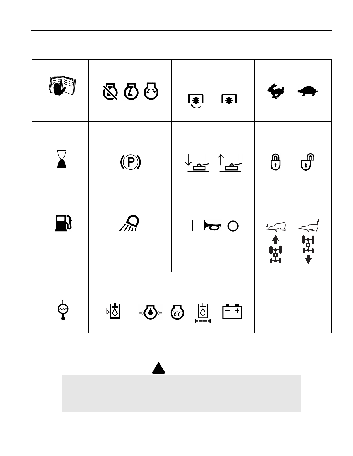
4.1 ICONS ____________ ___ __ ________________ _________________ ________________ _
Read Manual
Hour Meter
Fuel
D
Engine
Off Run
Parking Brake
Work Lights
Start
PTO
ON
Lower Raise
Oil Level Switch
On Off/Test
OFF
Mowers
Engine Throttle
High Low
Cruise Control
Lock Unlock
Travel
Forward Reverse
Coolant
Temperature
Never attempt to drive the trac tor unless you have read th e Safety and Operation Manua l
and know how to operate all controls correctly.
Familiarize yourself with the icons shown above and what they represent. Learn the
location and purpose of all the controls and gauges before operating this tractor.
Hydraulic Oil
Level
Warning Lights
Engine Oil
Pressure
Glow
Plug
Hydraulic
Oil Filter
WARNING
Battery
Charge
GB-7
Page 8

4 CONTROLS
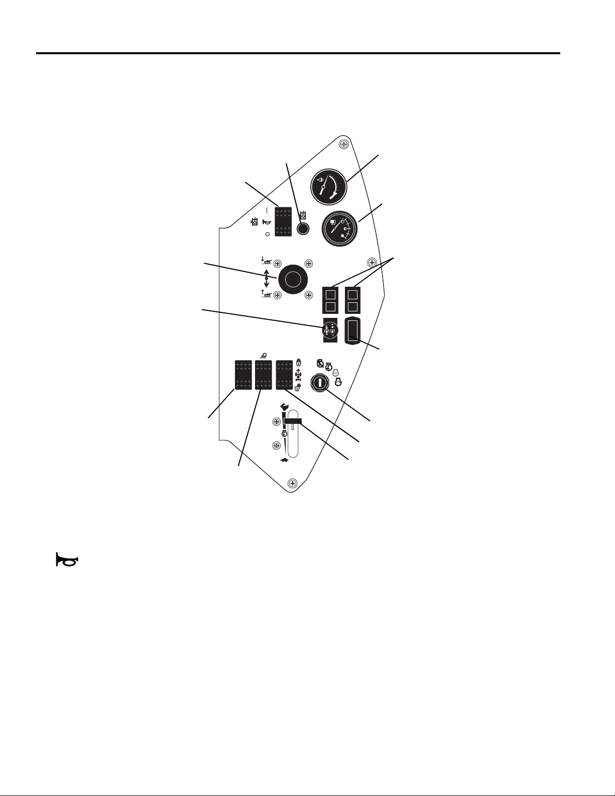
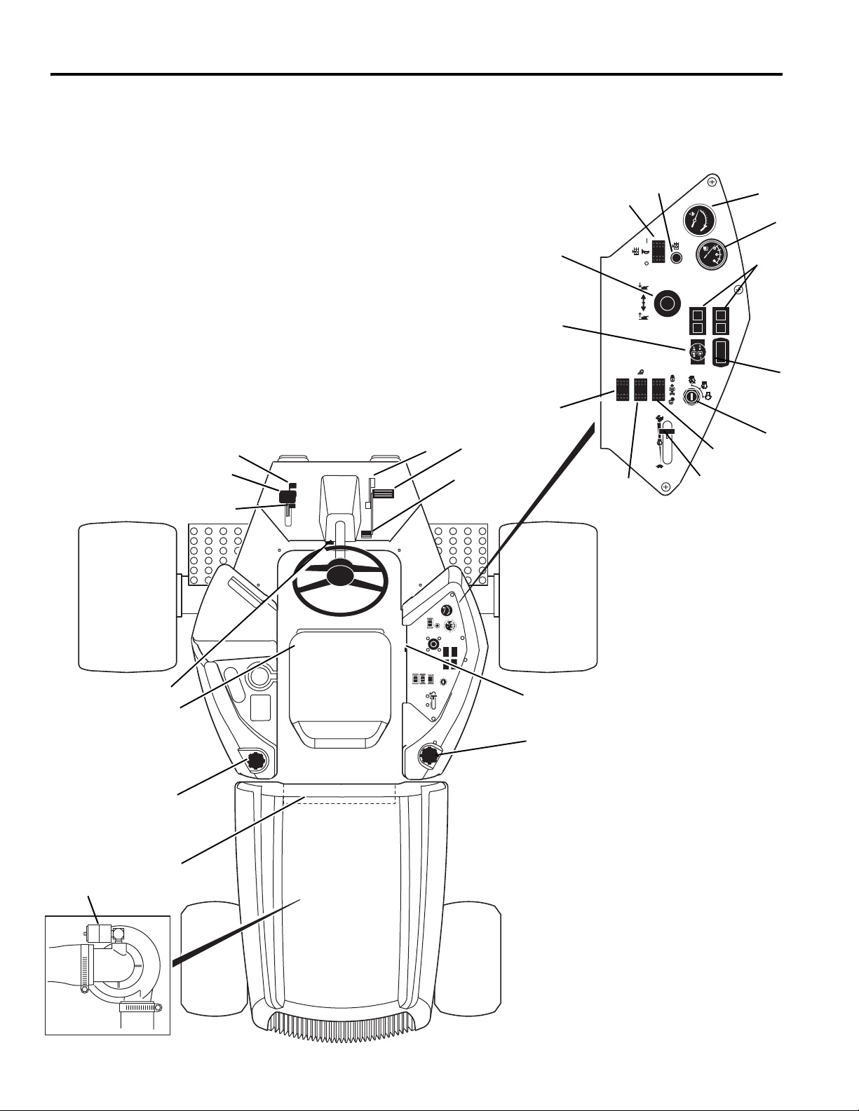
4.2 CONTROLS ______________________________________________________________
A Tilt Steering Lever
B1 Parking Brake Lock
B2 Parking Brake Release
C Parking Brake
D
Mow Speed Stop
E Traction Pedal - Forward
F Tr action Pedal - Reverse
G
Seat Adjustment
H Hydraulic Oil Cap/Dipstick
I Fuel Cap
J Air Cleaner Indicator
K (Not Used)
L Alarm
M Controller / Fuses
N Hyd. Oil Level Light
O Hyd. Oil Level Switch
P Mower Lift Lever
B
1
C
B
2
Q PTO Switch
R Traction Control
S Light Switch
T Engine Throttle
U Cruise Control (Option)
V Ignition Switch
W Hour Meter
X Fuel Gauge
Y Warning Lights
Z Engine Coolant
Temperature
D
N
O
Z
X
P
Y
Q
W
R
V
E
F
S
U
T
GB-8
A
L
G
I
H
M
J
Page 9
CONTROLS 4
!
!
A. Steering Tilt Control
Pull lever up to release steering column. Tilt column up
or down to position desired. Release lever to lock
steering column in place.
CAUTION: Never adjust steering while trac-
tor is moving. Stop unit and set parking brake
before adjustin
B. Parking Brake Lock/Release
To lock parking brake, hold brake pedal (C) down and
press lock (B
brake pedal release (B
Note: The engine will automatically shut down if the
traction pedal is held down for more than 10 seconds
with the parking brake engaged.
) until it engages. To disengage, press
1
C. Parking Brake
To engage parking brake press pedal down.
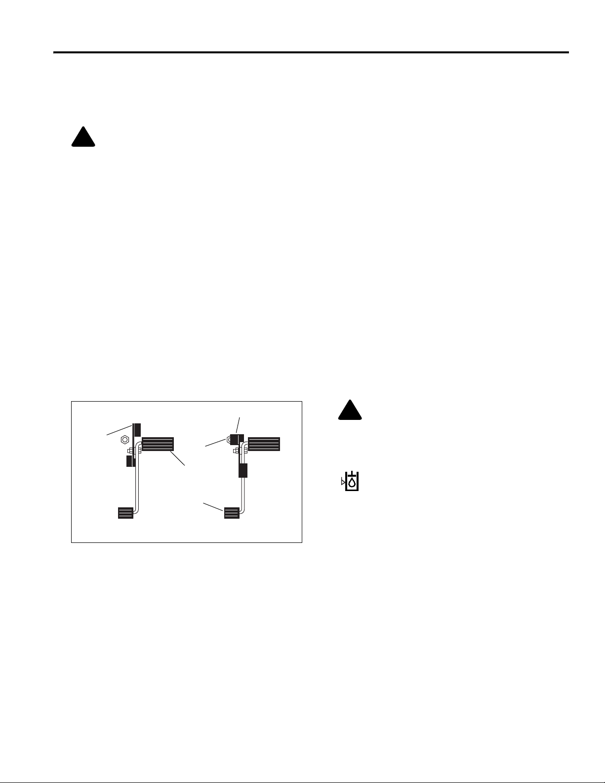
D. Mow Speed Stop
Limits forward speed while mowing. To operate at lower
travel speed while mowing, rotate lever so it contacts
stop screw (D
pedal is pressed. To travel at full speed, set lever in
position shown (D
set specific mow speeds. See Parts & Maintenance
Manual.
1
g.
).
2
) on floor board when forward travel
). Stop screw (D2) can be adjusted to
3
H. Hydraulic Oil Cap/Dipstick
Fill to mark on dipstick using clean hydraulic fluid while
machine is cool. Do not overfill
I. Fuel Cap
Fill fuel tank with No. 2 diesel fuel, minimum cetane
rating of 45. Section 5.11
J. Air Cleaner Indicator
Indicates condition of air cleaner on engine. Clean or
replace air filter when red band appears in clear window
of indicator. See Parts & Maintenance Manual
K. (Not Used)
L. Alarm
The alarm, along with the warning lights (N, Y), sounds
to alert the operator to conditions requiring immediate
attention. See Section 4.4.
M. Controller & Fuses
The controller is located under the rear hood directly
behind the operator’s seat. It is equipped with four
banks of LEDs to aid in monitoring and troubleshooting
the electrical system of the tractor. See Parts &
Maintenance Manual
Four spade type fuses are located next to the controller.
To replace fuses remove the front panel from the
controller.
D
1
D
3
D
2
E
F
Tra n sport Speed
E. Forward Travel (Traction Pedal)
Press front of pedal down for forward travel. Release
pedal to slow tractor and stop.
F. Reverse Travel (Traction Pedal)
Press rear of pedal down for reverse travel. Release
pedal to slow tractor and stop. Allow tractor to come to a
complete stop before reversing directions.
G. Seat Adjustment
Pull left side lever out to adjust seat froward or
backward. To adjust spring tension under seat turn
adjusting knob on front of seat.
Mow Speed
Figure 4A
LF002
CAUTION: Service to the electrical system
must be performed by a trained technician.
Before replacing fuses turn tractor off and
remove key from ignition.
N. Hydraulic Oil Level Light
Alerts the operator of a low fluid level in hydraulic tank. This light operates in combination with
the alarm. See Section 4.4.
Note: The warning light will remain on as long as a low
oil level is detected. If the alarm sounds due to low oil
level, it can be disabled by turning switch (O) to OFF.
GB-9
Page 10
4 CONTROLS
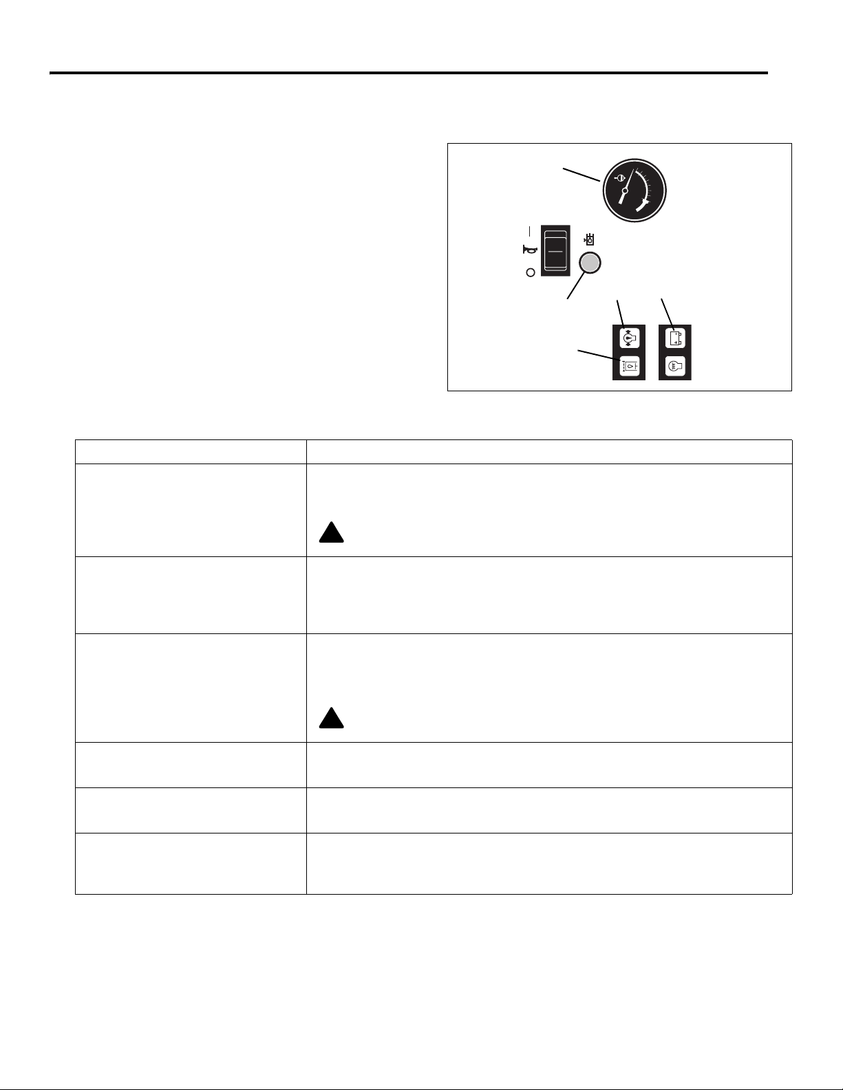
4.3 CONTROL PANEL _________________________________________________________
Q
P
R
O
N
Z
X
Y
W
V
S
O. Low Oil Level Switch
This switch is used to test the alarm system or
disable the alarm after a low oil level has been
detected. Keep switch in its ON position when
starting and operating tractor. To test alarm, set switch
to OFF and turn ignition key to RUN. See Section 4.4.
P. Mower Lift lever
The mower lever raises and lowers the mowers and
operates in either automatic or manual mode. Push
lever forward to lower mowers, pull back to raise
mowers.
Manual Mode - Set mow switch (Q) in its OFF (down)
position. In this position all mowers will raise or lower
while pressure is applied to the lift lever.
Automatic Mode - Set mow switch (Q) in its ON (up)
position. In automatic mode the mowers will lower and
start automatically with a momentary forward movement
of the lift lever. In this mode mowers will only raise to a
GB-10
U
T
Figure 4B
“crosscut” position with a momentary backward
movement of the lift lever.
To raise mowers to their transport position, hold lever
until mowers are fully raised.
To raise mowers to their transport position, hold lever
until mowers are fully raised.
NOTE: While in an Automatic Mode lift or lower cycle,
that lasts approximately 3 seconds, moving the lift lever
in the opposite direction will turn all mowers off and
manual mode will start for the position selected.
Q. PTO Switch
The PTO switch is a 2-position knob type switch used to
turns the mowers On or off. It also sets the mower lift
lever (P) in manual or automatic mode. Set mower
switch in its OFF (down) position when starting the
tractor.
Page 11

R. Traction Control
Press and release switch to activate traction control
system. This system
reduces down pressure on decks
by pulsing the lift circuit, transferring weight to tractor.
Reducing down pressure i mproves traction but may
cause decks to float up creati ng an unev en c ut. Light
in switch will turn on when system is active.
Press switch again to deactivate traction control. This
may reduce traction but improves dec k contact with
ground.
NOTE: The traction control system must be reset after
shutting off engine.
S. Lights
Controls operation of work lights.
T. Engine Throttle
Controls engine speed. Run machine at full throttle
during normal machine operation.
U. Cruise Control (Option)
When switched ON the cruise control will lock the
traction pedal in its current position. Cruise will unlock
when switched OFF, or if parking brake is applied.
CONTROLS 4
V. Ignition Switch
The ignition switch has three positions. OFF- RUN (ON)
- START. In the RUN (ON) position the controller
program is running and input and output circuits are
being monitored. See Section 5.4 and Parts &
Maintenance Manual.
W. Hour Meter
Records engine operating hours. Use hour meter to
schedule periodic maintenance.
X. Fuel Gauge
Indicates current fuel level. Check fuel gauge daily
before starting machine.
Y. Warning Lights
Alerts the operator to conditions requiring immediate
action. See Section 4.4.
Z. Temperature Gauge
Indicates engine coolant temperature. Normal operating
temperature should be between 160° - 230°F (71°110°C). If temperature rises above 230° (110°F), alarm
will sound. See Section 4.4.
GB-11
Page 12
4 CONTROLS
!
!
4.4 OPERATOR ALERTS _______________________________________________________
The electronic controller monitors vital machine systems. It
uses an audible alarm and warning lights to alert the
operator of conditions requiring immediate action. When an
alert occurs follow the general guidelines listed in the chart
below, and any specific actions outlined by the grounds
superintendent or service manager.
To test alarm system:
Turn ignition switch to RUN. All lights will come on for one
second or more and the alarm will sound briefly.
This system monitors:
1. Hydraulic fluid level
2. Engine oil pressure
3. Engine coolant temperature
4. Hydraulic oil filter
5. Battery voltage
6. Dual activation of brake and traction pedal.
Alert Action
3
2
5
1
4
LF004
Figure 4C
1. Hydraulic fluid level - alarm
sounds and hydraulic fluid warning
light comes on. Hydraulic fluid is
below recommended level.
2. Engine Oil Pressure - alarm
sounds and oil pressure light
comes on. Oil pressure low.
3. Engine Coolant Temperature
Alarm sounds. Engine coolant
temperature high.
4. Hydraulic oil filter - Oil filter
warning light remains on.
5. Battery Voltage - Warning light
comes on.
6. Driving with brake on - Alarm
Sounds
Stop tractor immediately, lower implements and shut off engine! Visually
inspect tractor for obvious signs of leaks around connections, hoses and
hydraulic components. Return tractor to service area for maintenance.
CAUTION: Hydraulic fluid is under pressure. Turn engine off and allow
fluid to cool before checking fluid level or adding oil to hydraulic tank.
Stop tractor immediately, lower implements and shut off engine! Inspect oil
level in engine. If oil light remains on with oil at proper level, shut off engine and
tow or trailer tractor back to a service area. NEVER operate engine with oil light
on, severe damage to the engine can occur.
Stop tractor immediately, lower implements and shut off engine! Remove
debris such as leaves and grass clippings that may be restricting air flow through
rear screen on hood and area between radiator and oil cooler. If engine
continues to run hot, return tractor to a service area.
CAUTION: Engine coolant is under pressure. Turn engine off and allow
fluid to cool before checking fluid level or adding coolant to radiator.
Return tractor to a service area as soon as possible. Change hydraulic oil
filters.
Return tractor to a service area as soon as possible. Inspect battery and
battery charging system.
Disengage parking brake, or remove foot pressure from either pedal.
Continued operation with both brake and traction pedal depressed will cause
engine to stop in 10 - 60 seconds, depending on the order of pedal application.
GB-12
Page 13

OPERATION 5
!
!
5 OPERATION
5.1 DAILY INSPECTION_________________________ __ ________________ _____________
2. Check the fuel supply, radiator coolant level, crankcase
CAUTION
The daily inspection should be performed only when
the engine is off and all fluids are cold. Lower mowers
to the ground, engage the parking brake, Stop engine
and remove ignition key.
oil and air cleaner indicator. All fluids must be at the full
level mark with engine cold.
3. Make sure all mowers are adjusted to the same cutting
height.
4. Visually check tires for proper inflation.
1. Perform a visual inspection of the entire unit, look for
signs of wear, loose hardware, and missing or damaged
components. Check for fuel or oil leaks to ensure connections are tight and hoses and tubes are in good condition.
5. Test the interlock system.
Note: For more detailed maintenance information,
adjustments and maintenance/lube charts, see the
Parts & Maintenance manual.
5.2 Interlock System __________________________________________________________
1. The interlock system prevents the engine from starting
unless the parking brake is engaged, the traction pedal
is in neutral and the mower switch(es) is “OFF”. The
system also stops the engine if the operator leaves the
seat with the mower switch(es) “ON”, traction pedal out
of NEUTRAL, or parking brake “DISENGAGED”.
WARNING
Never operate equipment with the Interlock System
disconnected or malfunctioning. Do not disconnect or
bypass any switch.
2. Perform each of the following tests to insure the
interlock system is functioning properly. Stop the test
and have the system inspected and repaired if any of
the tests
● the engine does not start in test 1;
● the engine does start during tests 2,3 or 4;
● the engine continues to run during tests 5 or 6.
fail as listed below:
3. Refer to the chart below for each test and follow the
check (
between each test.
Test 1: Represents normal starting procedure. The
operator is seated, parking brake is engaged, the
operator’s feet are off the pedals, and the mower
switch(es) is ‘OFF”. The engine should start.
Test 2: The engine must not start if the mower switch is
“ON”.
Test 3: The engine must not start if the parking brake is
“DISENGAGED”.
Test 4: The engine must not start if the traction pedal is
pressed.
Test 5: Start the engine in the normal manner then turn
mower switch “ON” and lift your weight off the seat.
Test 6: Start the engine in the normal manner then
disengage parking brake and lift your weight off the
seat.
9) marks across the chart. Shut engine off
Interlock System Check
Test
1
2
3
4
5
6
Operator
Seated
Yes No On Off Yes No On Off Yes No
Parking
Brake
Traction Pedal
in Neutral
Mower
Switch
Engine
Starts
999 99
9999 9
99999
99 999
9999
9 99 9
Lift your weight off seat. The cutting units must stop rotating within seven (7) seconds.
GB-13
Page 14

5 OPERATION
!
!
!
!
5.3 OPERATING PROCEDURES_________________________________________________
WARNING
A Rollover Protection Structure (RO PS) for this tractor i s available as an optio nal accessory. Evaluate the terrain
and working conditions to dete r min e i f a ROP S i s requi red. S ea t bel ts mus t b e worn when ev er a ROP S i s ins talle d
on the tractor. Always keep seat belt snugly adjusted. DO NOT use seat belts on a tractor without a ROPS.
If a ROPS is installed and the tract or is overturning, hold onto the steer ing wheel. Do not attempt to jump out or
leave the seat.
CAUTION
To prevent injury, always wear safety glasses, leather work shoes or boots, a hard hat, and ear protection.
1. Under no circumstances should the engine be
started without the operator seated on the tractor.
Never start the engine with operator or bystanders
standing behind a discharge chute.
2. Never run the engine in an enclosed area.
3. Keep hands and feet away from moving parts and
cutting units. If possible, do not make adjustments with
the engine running.
4. Do not operate tractor or attachments with loose,
damaged or missing components. Whenever
possible mow when grass is dry.
5. First mow in a test area to become thoroughly
familiar with the operation of the tractor and control
levers.
6. Study the area to determine the best and safest
operating procedure. Consider the height of the
grass, type of terrain, and condition of the surface.
Each condition will require certain adjustments or
precautions.
7. Be aware of mower discharge direction and never
direct discharge of material toward bystanders.
Never allow anyone near the machine while in
operation. The owner/operator is responsible for
injuries inflicted to bystanders and/or damage to
their property.
CAUTION
Before mowing, pick up all debris such as rocks, toys
and wire which can be thrown by the machine. Enter a
new area cautiously. Always operate at speeds that
allow you to have complete control of the mower.
8. Use discretion when mowing near gravel areas
(roadway, parking areas, cart paths, etc.). Stones
discharged from the implement may cause serious
injuries to bystanders and/or damage the
equipment.
9. Always turn PTO switch off to stop blade s when not
mowing.
10. Disengage the drive motors, raise the mowers and
slow down when crossin g paths or roadways. L ook
out for traffic.
11. Stop and inspect the equipment for damage
immediately after striking an obstruction or if the
machine begins to vibrate abnormally. Have the
equipment repaired before resuming operation.
WARNING
Before you clean, adjust, or repair this
equipment, always disengage all drives, lower
implements to the groun d, e ngag e parki ng b r ake ,
stop engine and remov e key from ignition swi tch
to prevent injuries.
12. Slow down and use extra care on hillsides. Read
Section 5.10. U se caution when operating n ear drop
offs.
13. Look behind and down before backing up to be sur e
the path is clear. Use care when approaching blind
corners, shrubs, tress or other objects that may
obscure vision.
14. Never use your hands to clean cuttin g units. Use a
brush to remove grass clippings from blades.
Blades are extremely sha rp and can cause serious
injuries.
GB-14
Page 15

OPERATION 5
!
5.4 STARTING________________________________________________________________
IMPORTANT: Do not use starting assist fluids. Use of
such fluids in the air intake system may be potentially
explosive or cause a “Runaway” engine condition and could
result in serious engine damage.
WARNING
To prevent injuries, sit in the seat, engage
parking brake, place tracti on pedal in neutral an d
PTO switch in OFF position before attemp ting to
start the engine.
1. Sit in operator’s seat, make sure the PTO switch (Q) is
“OFF” (down) and the parking brake is engaged.
Remove feet from pedals. Always use the seat belt
when operating tractors equipped with a ROPS.
2. Set throttle lever (T) to half throttle and check that
alarm switch (O) is “ON”.
3. Turn ignition switch (V) to “ON” ( ) position.
Note: At this time the warning lights (N, Y) on the
instrument panel will come on. Check that lights are
operating.
4. Wait until glow plug light goes out, then immediately
turn ignition key to “START” ( ) position. Release as
soon as engine starts.
Note: Do not hold key in “ST ART” position for more than
10 seconds at a time. After 10 seconds the starting
circuit will shutdown and must be reset by returning the
key to the OFF position.
Allow 30 seconds between start-up attempts to allow
time for engine starter motor to cool.
All warning lights should go off after engine starts.
Allow engine to gradually become warm before
operating at high RPM.
N
O
Q
Y
V
T
LF003
Figure 5A
5.5 STOPPING / PARKING______________________________________________________
To stop:
Remove your foot from traction pedal.
automatically brake when the traction pedal returns to
neutral.
remove key before leaving operator seat for any reason.
To park the tractor under normal conditions:
1. Disengage the PTO switch (Q) then raise and lock the
2. Select a flat and level area to park.
Always engage parking brake, shut off engine and
implements in the transport position and move away
from the area of operation.
a. Release traction pedal to bring the tractor to a com-
plete stop.
b. Disengage all drives, lower implements to the
ground, engage parking brake, reduce throttle to
idle and allow engine to operate at no load for three
to five minutes.
The tractor will
Permanent damage to th e turbocharger may occur if
the engine is shut down without allowing the
turbocharger time to cool.
To prevent damage, operate the engine at idle with no
load for 3 to 5 minutes before shutting off engine.
3. Engage parking brake, stop the engine and always
remove the ignition key.
If an emergency arises and the tractor must be parked in the
area of operation, follow the guidelines outlined by the
grounds superintendent.
If the tractor is parked on an incline, chock or block the
wheels.
CAUTION
GB-15
Page 16

5 OPERATION
!
5.6 TO DRIVE / TRANSPORT____________________________________________________
Read and follow all safety notes contained in this manual
when driving or transporting tractor. When operating in
reverse look behind you to ensure you have a clear path.
Important: If this tractor is driven on public roads, it must
comply with federal, state and local ordinances. Contact
local authorities for regulations and equipment
requirements.
To raise mowers to their transport position:
Set PTO switch to OFF (center position). Pull mower lever
back. Hold lever until mowers are up and lift arms are in their
fully raised (transport) position.
Important: The mow switch should be OFF (center position)
while transporting tractor.
5.7 MOWING_________________________________________________________________
position. To lift mowers to their transport position
WARNING
To prevent serious injuries, keep hands, feet and
clothing away from cutting unit when the blades are
moving.
NEVER use your hands to clean cutting units. Use a
brush to remove grass clippings from b lades. Blades
can be sharp and could cause injuries.
DO NOT operate mowers without rear discharge
chutes or mulching plate installed.
To mow:
1. Set PTO switch to its ON (Up) position. This also sets
the mower lever to automatic mode. See Mower Lift
Lever, page 8.
2. Press mower lever forward momentarily to lower
mowers. Mowers will begin turning automatically when
cutting units have lowered.
3. To lift mowers, pull mower lever back and release.
Mowers will stop turning and raise to their crosscut
continue to hold lever until mowers are completely
raised.
4. Activate traction control (R) as required to improve
weight distribution between decks and tractor. [See
4.3]
Always mow with the engine at full throttle.
To install mulching plate:
An optional mulching plate can be used instead of the rear
discharge chute. Do not operate mower without rear
discharge chute or mulching plate installed.
1. Place PTO switch in OFF (down) position, lower mowers to the ground, engage parking brake and stop
engine.
2. Remove three nuts securing discharge chute to mower
housing.
3. Remove discharge chute and assemble mulching
plate. Secure with three nuts remove previously. Store
the discharge chute in a safe location for future use.
5.8 MOWING SPEED __________________________________________________________
Cutting quality is better at speeds well below the transport
speed of the tractor. An initial mow speed of 6 to 7 MPH (10
to 11 kph) is set at the factory and should be satisfactory for
most cutting conditions. Local turf conditions however may
respond better to a different speed. If an adjustment is
needed, refer to the Parts and Maintenance manual.
GB-16
Page 17

OPERATION 5
!
!
5.9 TOWING / TRAILERING _____________________________________________________
If the tractor experiences problems and must be shut down
and removed from the area, it should be loaded onto a trailer
for transport. If a trailer is not available, the unit can be
towed slowly short distances.
Use care when loading and unloading tractor. Fasten tractor
to trailer to prevent tractor from rolling or shifting during
transport.
Long Distance Trailering / Transport. If the tractor is to
be trailered on the highway, before strapping to trailer,
close fuel shut off valve and inflate tires maximum
pressure listed on side of tire. Reduce tire pressure to
normal after removing from trailer. [See 5.9]
Before towing, open tow valve. The tow valve permits
moving the tractor without starting the engine and prevents
possible damage to hydraulic components.
The tow valve (A) is located on the hydraulic drive pump
beneath the operators seat. Remove cover from floor in front
of operator’s seat. To open valve, use a wrench or insert a
pin or small screw driver into the small hole in the valve
stem. Turn the valve counterclockwise one full turn.
Before towing make sure cutting units are raised. If they
cannot be raised, remove them from the tractor.
Close valve completely and replace cover after towing.
NOTE: Do not exceed 2 MPH (3.2 KPH) while towing. Long
distance towing is not recommended
.
A
LF006
Figure 5B
5.10 HILLSIDE OPERATION _____________________________________________________
3. If the tractor tends to slide or the tires begin to “mark”
WARNING
To minimize the possibility of overturning, the safest
method for operating on hills and terraces is to travel up
and down the face of the slope (vertically), not across the
face (horizontally). Avoid unnecessary turns, travel at
reduced speeds, and stay alert for hidden hazards.
CAUTION
A Rollover Protection System (ROPS), designed for this
tractor, is available as an optional accessory.
ROPS before operating on slopes greater than 14°.
Do not operate this tractor on slopes greater than 20°.
The tractor has been designed for good traction and stability
under normal mowing conditions; however, use caution
when operating on slopes, especially when the grass is wet.
Wet grass reduces traction and steering control.
1. Always mow with the engine at full throttle but reduce
forward speed to maintain the proper cutting frequency.
Install a
the turf, angle tractor into a less steep grade until
traction is regained or tire marking stops.
4. If tractor continues to slide or mark the turf, the grade
is too steep for safe operation. Do not make another
attempt to climb, back down slowly.
5. When descending a steep slope, always lower
implements to the ground to reduce the risk of tractor
overturning.
Correct tire pressure is essential for maximum traction.
Front .........................16 psi (111 kPa)
Rear.......................... 12 psi (86 kPa)
2. Activate traction control (R) as required to improve
weight distribution between decks and tractor. [See
4.3]
GB-17
Page 18

5 OPERATION
!
!
!
5.11 DAILY MAINTENANCE _____________________________________________________
Important: For more detailed maintenance information,
adjustments and maintenanc e/lubricatio n charts, see the
Parts& Maintenance manual.
1. Park the tractor on a flat and level surface. Fully
lower the cutting units to the ground, enga ge parking
brake, stop the engine and remove the key from ignition switch.
2. Grease and lubricate all points if required. To
prevent fires, wash the cuttin g units and tractor after
each use.
To prevent serious injury from hot, high pressure
oil, never use your h ands to check for oil leaks,
use paper or cardboard.
Hydraulic fluid escapi ng und er pres su re c an h ave
sufficient force to penetrate skin. If fluid is injected
into the skin, it must be s urgicall y remo ved within
a few hours by a doctor famili ar with this form of
injury or gangrene may result.
WARNING
a. Do not use high pressure spray.
b. Do not spray water directly at the instrument
panel, or any electrical components.
c. Do not spray water into coolin g air in take, or the
engine air intake.
Note: Do not wash a hot or running engine. Use
compressed air to clean the engine and radiator fins.
d. Clean the tires thoroughly. Check tire pressure.
e. Clean radiator and oil cooler passages using com-
pressed air (30 psi maximum).
3. Fill the tractors fuel tank at the end of each
operating day to within 1 in., (2 5 mm) below the fill er
neck.
Use clean fresh #2 diesel fuel. Minimum Cetane
Rating 45.
4. Handle fuel with care - it is highly flammable. Use
an approved container, the spout must fit inside the
fuel filler neck. Avoid using cans and funnels to
transfer fuel.
a. Never remove the fuel cap from the fuel tank, or
add fuel, when the engi ne is run ni ng or while th e
engine is hot.
b. Do not smoke when handling fuel. Never fill or
drain the tank indoors.
c. Never ov erfi ll or a llow th e tank to bec ome em pty.
Do not spill fuel. Clean any spilled fuel
immediately.
6. Inspect hydraulic hoses and tubes daily. Look for
wet hoses or oil spots and replace worn or
damaged hoses and tubes before operating the
machine.
WARNING
To prevent serious bodily injury from hot coolant or
steam blow-out, nev er attempt to remo ve the radiator
cap while the engine is running. Stop the engine an d
wait until it is cool. Even then, use extreme care when
removing the cap.
CAUTION
Do not pour cold water into a hot radiator. Do not operate
engine without a proper coolant mixture. Install cap and
tighten securely.
7. After engine has cooled, check coolant level.
Radiator should be full and recovery bottle should be
up to the cold mark.
8. Park machine in designated area. Engage parking
brake and remove key. Place key in a secure
location to prevent unauthorized use of equipment.
9. Check the engine oil and hydraulic oil at the start
and end of each day. If the oil level is low, remove
the oil filler cap and add oil as required. Do not
overfill.
d. Never handle or store fuel containers near an
open flame or any device t hat ma y create sparks
and ignite the fuel or fuel vapors.
5. Store fuel according to local, state or federal
ordinances and recommendations from your fuel
supplier.
GB-18
Page 19

OPERATION 5
!
!
5.12 LONG TERM S T ORA GE_________________ __ _________________ __ _______________
General
1. Wash the tractor thoroughly and lubricate. Repair and
paint damaged or exposed metal.
2. Inspect the tractor, tighten all hardware, replace worn
or damaged components.
3. Drain and refill radiator.
4. Clean the tires thoroughly and store the tractor so the
load is off the tires. If tractor is not on jack stands,
check tires at regular intervals and reinflate as
necessary.
5. Keep the machine and all its accessories clean, dry
and protected from the elements during storage. Never
store equipment near an open flame or spark which
could ignite fuel or fuel vapors.
Battery
1. Remove, clean and store battery in upright position in a
cool, dry place.
2. Check and recharge battery every 60 to 90 days while
in storage.
3. Store batteries in a cool, dry place. To reduce the self
discharge rate, room temperature should not be above
80°F (27°C) or fall below 20°F (-7°C) to prevent
electrolyte from freezing.
After Storage
1. Check and reinstall battery
2. Check or service fuel filter and air cleaner.
3. Check the radiator coolant level.
4. Check oil level in the engine crankcase and hydraulic
system.
5. Fill the fuel tank with fresh fuel. Bleed the fuel system.
6. Make certain that the tires are properly inflated.
7. Remove all oil from the blades. Adjust cutting height.
8. Start and operate the engine at 1/2 throttle. Allow
enough time for the engine to become properly
warmed and lubricated.
WARNING
Never operate the engine without proper ventilation;
exhaust fumes can be fatal when inhaled.
Engine
1. While the engine is warm, remove drain plug, drain the
oil from the crankcase and change oil filter. Install drain
plug and refill with fresh oil. Torque drain plug to 22 ft.
lb. (30 Nm).
2. Clean exterior of engine. Paint exposed metal or apply
a light coat of rust preventative oil.
3. Add a fuel conditioner or biocide to prevent gelling or
bacterial growth in fuel. See your local fuel supplier.
Cutting Units
1. Wash the cutting units thoroughly, then repair and paint
any damaged or exposed metal.
2. Lubricate all fittings and friction points.
3. Apply a light coat of rust preventative oil to the
sharpened edges of the blades.
CAUTION
To prevent personal injury and damage to the cutting
edges, handle the blades with extreme care
GB-19
Page 20

ESIPUHE
Tämä ohje sisältää uuden Jacobsen-traktorisi käyttö- ja
turvallisuusohjeet. Ohjeisiin sisältyy myös osaluettelo ja
huolto-ohje, jossa on säätö- ja huolto-ohjeet sekä
vianmääritysosio ja osaluettelo. Molemmat ohjekirjat on
säilytettävä istuimen takana sijaitsevassa pussissa, joka on
tarkoitettu huolto-ohjeille ja josta ne ovat nopeasti saatavilla.
Ennen kuin käytät konetta sinun, sekä kaikkien koneen
käyttäjien, on luettava molemmat käsikirjat huolellisesti ja
kokonaisuudessaan. Seuraamalla turvallisuus-, käyttö- ja
huolto-ohjeita pidennät koneesi elinikää ja pidät yllä sen
parhaan mahdollisen suorituskapasiteetin.
Jos haluat lisätietoja, ota yhteyttä lähimpään Jacobsenjälleenmyyjääsi.
SISÄLLYSLUETTELO
SISÄLLYSLUETTELO
SISÄLLYSLUETTELO
TURVALLISUUS
1.1 Käyttöturvallisuus. . . . . . . . . . . . . . . . . . . . . 3
1.2 Tärkeitä huomautuksia . . . . . . . . . . . . . . . . . 4
MERKINNÄT
ALKUTARKISTUS
3.1 Yleistä . . . . . . . . . . . . . . . . . . . . . . . . . . . . . .6
3.2 Alkutarkistus. . . . . . . . . . . . . . . . . . . . . . . . . .6
SÄÄTIMET
4.1 Kuvakkeet . . . . . . . . . . . . . . . . . . . . . . . . . . . 7
4.2 Säätimet . . . . . . . . . . . . . . . . . . . . . . . . . . . . 8
4.3 Kojetaulu . . . . . . . . . . . . . . . . . . . . . . . . . . . 10
4.4 Varoitukset . . . . . . . . . . . . . . . . . . . . . . . . . 12
Koneen sarjanumero sijaitsee istuinkaukalossa istuimen
vasemmalla puolella. Jacobsen-yhtiö suosittelee, että
kirjoitat sarjanumeron muistiin, jotta se on tarvittaessa
kätevästi saatavilla.
®
A Textron Company
CHARLOTTE, NC MADE IN U.S.A.
68080
KÄYTTÖ
5.1 Päivittäinen tarkastus . . . . . . . . . . . . . . . . . .13
5.2 Lukitusjärjestelmä . . . . . . . . . . . . . . . . . . . .13
5.3 Ohjaustoimet . . . . . . . . . . . . . . . . . . . . . . . .14
5.4 Käynnistäminen . . . . . . . . . . . . . . . . . . . . . .15
5.5 Pysäyttäminen ja pysäköiminen . . . . . . . . .15
5.6 Ajaminen ja kuljettaminen . . . . . . . . . . . . . .16
5.7 Leikkaaminen . . . . . . . . . . . . . . . . . . . . . . . .16
5.8 Leikkuunopeus . . . . . . . . . . . . . . . . . . . . . . .16
5.9 Hinaaminen ja vetäminen . . . . . . . . . . . . . .17
5.10 Rinnekäyttö . . . . . . . . . . . . . . . . . . . . . . . . .17
5.11 Päivittäinen huolto . . . . . . . . . . . . . . . . . . . .18
5.12 Säilytys . . . . . . . . . . . . . . . . . . . . . . . . . . . .19
Varoitus
Tämän laitteen pakokaasu sisältää
kemikaaleja, jotka Kalifornian
osavaltion tietojen mukaan aiheuttavat
syöpää, synnynnäisiä vammoja ja
muita lisääntymishäiriöitä.
© COPYRIGHT 2004, TEXTRON INC.
“Kaikki oikeudet pidätetään. Tätä opasta tai sen osaa ei saa kopioida missään muodossa.”
Kaikki tässä julkaisussa olevat tiedot perustuvat ennen painamista käytössä olleisiin tietoihin. Jacobsen pidättää oikeuden
tehdä muutoksia milloin tahansa sitoumuksetta ja ilman erillistä ilmoitusta.
VALMISTUS YHDYSVALLOISSA 5-2004
FI-2
Page 21

TURVALLISUUS 1
!
1 TURVALLISUUS
1.1 KÄYTTÖTURVA LLIS U US__________________ ___ __ __ _________________ __ __ ______
VAROITUS
JOS LAITETTA KÄYTETÄÄN VÄÄRIN TAI SITÄ KÄYTTÄÄ HENKILÖKUNTA, JOTA EI OLE KOULUTETTU KO.
LAITTEEN KÄYTTÖÖN, SE VOI OLLA VAARALLINEN.
Tutustu alueeseen ja kaikkien hallintalaitteiden käyttöön. Kokemattomat kuljettajat on perehdytettävä laitteeseen ennen
kuin heidän sallitaan käyttää sitä.
1. Turvallisuus riippuu laitteen käyttäjien ja huoltajien
valppaudesta, huolellisuudesta ja varovaisuudesta. Älä
koskaan anna alaikäisten käyttää laitteita.
2. Sinun vastuullasi on lukea tämä käsikirja ja kaikki muut
laitteeseen liittyvät julkaisut (Käyttö- ja
turvallisuusopas, moottorin käyttöopas, lisälaitteet ja
varusteet). Jos käyttäjä ei osaa lukea englanninkielistä
ohjekirjaa, omistajan vastuulla on selittää heille tässä
ohjekirjassa annettu materiaali.
3. Opettele käyttämään konetta oikein sekä kaikkien
hallintalaitteiden ja mittareiden sijainti ja käyttö ennen
kuin käytät konetta. Outojen laitteiden kanssa
työskenteleminen voi johtaa tapaturmiin.
4. Älä koskaan anna kenenkään käyttää tai huoltaa
konetta tai sen lisälaitteita ilman asianmukaista
koulutusta ja ohjeita, tai alkoholin tai huumeiden
vaikutuksen alaisena.
5. Käytä tarvittavia suojahaalareita ja henkilösuojaimia
pään, silmien, korvien, käsien ja jalkojen suojana.
Käytä konetta ainoastaan päivänvalossa tai hyvässä
keinovalaistuksessa.
6. Arvioi maasto, jotta voit päätellä mitä apuvälineitä
tarvitset työn turvalliseen ja kunnolliseen
suorittamiseen. Käytä vain apuvälineitä ja lisälaitteita,
jotka Jacobsen on hyväksynyt.
7. Pysy valppaana maassa olevien kuoppien tai muiden
näkymättömien vaaratekijöiden varalta.
8. Tarkista alue, jossa laitetta käytetään. Poimi kaikki
roskat maasta ennen käyttöä. Varo pään yläpuolella
olevia esteitä (matalalla roikkuvia puun oksia,
sähköjohtoja jne.) ja maanalaisia esteitä (sadettajat,
putket, puun juuret jne.) Tutustu uuteen alueeseen
varovasti. Pysy valppaana näkymättömien
vaaratekijöiden varalta.
9. Älä koskaan suuntaa poistoaukkoa kohti
sivustakatsojia tai salli kenenkään tulla liian lähelle
konetta silloin, kun se on käynnissä. Omistaja / käyttäjä
on vastuusta itselleen, sivustakatsojille ja omaisuudelle
aiheutuneista vahingoista ja velvollinen estämään ne.
10. Älä ota matkustajia. Pidä sivustakatsojat ja
lemmikkieläimet riittävän etäisyyden päässä.
11. Älä koskaan käytä laitetta, joka ei ole erinomaisessa
toimintakunnossa tai jonka tarrat, suojakaiteet, kilvet,
poistoaukon ilmansuuntain tai muut suojavarusteet
eivät ole tiukasti paikoillaan.
12. Älä poista käytöstä tai ohita mitään kytkintä.
13. Älä muuta moottorin käynnintasaimen säätöjä tai aja
ylinopeutta.
14. Pakokaasujen hiilimonoksidi voi olla hengenvaarallista.
Älä koskaan käytä moottoria suljetussa tilassa tai
paikassa, jossa ei ole kunnollista ilmanvaihtoa.
15. Polttoaine on tulenarkaa, käsittele sitä varoen.
16. Pidä moottori puhtaana. Anna moottorin jäähtyä ennen
varastointia ja poista aina virta-avain varastoinnin
ajaksi.
17. Vapauta kaikki vaihteet ja kytke käsijarru päälle ennen
kuin käynnistät moottorin. Käynnistä moottori vain
silloin, kun itse istut kuljettajan paikalla.
18. Laitteiden on oltava voimassa olevien kansallisten ja
paikallisten lakien mukaisia, jos ajoneuvolla liikutaan
maanteillä. Varo muuta liikennettä, jos olet ylittämässä
tietä tai toimit teiden lähettyvillä.
19. Paikalliset lait voivat rajoittaa kuljettajan ikävaatimusta.
20. Älä koskaan yritä etsiä vuotoja käsin. Paineistettu
hydraulineste voi läpäistä ihon ja aiheuttaa vakavan
vamman.
21. Aja rinteissä ala- ja ylämäkeen (pystysuunnassa), älä
sivuttain (vaakasuunnassa).
22. Älä käynnistä tai pysäytä laitetta äkillisesti rinteissä,
jotta se ei kaatuisi etkä menettäisi laitteen hallintaa.
Vähennä nopeutta jyrkissä mutkissa. Ole varovainen
vaihtaessasi suuntaa.
23. Käytä aina turvavyötä, kun ohjaat ROPSturvaohjaamolla varustettua traktoria.
Älä koskaan käytä turvavyötä, kun ohjaat traktoria,
jossa ei ole ROPS-turvaohjaamoa.
24. Pidä kädet, jalat ja vartalo istuinosan sisäpuolella
ajoneuvon ollessa liikkeellä.
Tätä laitetta on käytettävä ja huollettava tässä oppaassa kuvattavalla tavalla. Laite on tarkoitettu erityisten
ruohoturvekenttien ammattimaiseen huoltoon. Sitä ei ole tarkoitettu käytettäväksi epätasaisessa maastossa eikä
pitkässä ruohikossa.
FI-3
Page 22

1 TURVALLISUUS
!
!
1.2 TÄRKEITÄ HUOMAUTUKSIA ________________________________________________
Tämä varoitusmerkki varoittaa sinua mahdollisista vaaratekijöistä.
!
HENGENVAARA - Osoittaa välitöntä vaaratil annetta, joka JOHTAA kuolemaan tai vakavaan lou kkaantum iseen,
jos sitä ei pystytä välttämään.
VAROITUS - Osoittaa mahdollis ta vaar ati la nne tta, joka VOI johtaa kuolemaan tai vakavaan louk k aan tumi seen , jos
sitä ei pystytä välttämään.
VAARA - O soittaa mahdollista vaarati lannetta, joka VOI johtaa lievää n tai vakavaan louk kaantumisee n tai kiinteän
omaisuuden vahingoittumiseen, jos sitä ei pystytä välttämään. Voidaan käyttää myös osoittamassa vaarallista
käyttötapaa.
Jotta tämän käyttöoppaan kuvat olisivat mahdollisimman selkeitä, joissakin kuvissa suojukset tai kannet on voitu avata
tai poistaa. Laitetta ei kuitenkaan saa missään olosuhteissa käyttää ilman, että ne on kiinnitetty tiukasti paikoilleen.
VAROITUS
Tämän traktorin lukitusjärjestelmä estää traktorin käynnistymisen, jollei jarrupoljin
ole painettuna, leikkuukytkin poissa päältä ja vetopoljin vapaalla. Järjestelmä
sammuttaa moottorin, jos käyttäjä nousee istuimelta kytkemättä seisontajarrua tai
kytkemättä leikkuukytkintä pois päältä.
ÄLÄ KOSKAAN käytä traktoria, jos lukitusjärjestelmä ei toimi.
VAROITUS
1. Toimi aina seuraavasti, ennen kuin lähdet käyttäjän istuimelta:
a. Vaihda vetopoljin vapaalle.
b. Vapauta kaikki käyttölaitteet.
c. Laske kaikki leikkuuyksiköt maahan.
d. Kytke seisontajarru.
e. Sammuta moottori ja poista virta-avain.
2. Pidä kädet, jalat ja vaatteet erossa liikkuvista osista. Odota, että kaikki liikkuvat
osat pysähtyvät, ennen kuin alat puhdistaa, säätää tai huoltaa laitetta.
3. Älä laske käyttöalueelle sivustakatsojia tai eläimiä.
4. Älä koskaan ota matkustajia, jollei traktorissa ole heitä varten tarkoitettua
istuinta.
5. Älä koskaan käytä ruohonleikkuukonetta, jos poistoaukon suuntainta ei ole
kiinnitetty tiukasti paikalleen.
Noudattamalla tässä käyttöoppaassa annettavia ohjeita pidennät laitteen käyttöikää ja ylläpidät sen maksimaalista
tehokkuutta. Säätöjä ja huoltotoimia saa tehdä vain niihin koulutuksen saanut henkilö.
Jos tarvitset lisätietoja tai jos laitetta on huollettava, ota yhteys Jacobsen in valtuutettuun jälleenmyyjään, jolla on
viimeisimmät tiedot laitteen huoltotoimista ja jolta saa nopeaa ja tehokasta palvelua. Muiden kuin alkuperäisten tai
valtuutettujen Jacobsen -osien ja lisävarusteiden käyttö mitätöi takuun.
FI-4
Page 23

MERKINNÄT 2
2 MERKINNÄT
Tutustu merkintöihin. Niiden tunteminen on erittäin tärkeää laitteen turvallisen käytön
kannalta. KORJAA VIOITTUNEET MERKINNÄT HETI.
VAROITUS
!
1. Lue käyttöohje. Älä anna
kouluttamattomien käyttäjien
käyttää konetta.
2. Pidä suojalaitteet paikoillaan
ja varmista, että kaikki osat
ovat tiukasti kiinni.
3. Vapauta kaikki käyttölaitteet,
kytke seisontajarru ja
sammuta moottori ennen
laitteen puhdistamista,
säätämistä ja korjaamista.
4. Pidä kädet, jalat ja vaatteet
erossa liikkuvista osista.
5. Älä ota matkustajia.
6. Pidä sivustakatsojat loitolla.
7. Tarkista letkut ja
kangaspeitteet päivittäin. Jos
ne ovat kuluneet tai
vaurioituneet, vaihda
alkuperäisiin laatuosiin.
Älä käytä laitetta rinteissä ,
8.
joiden kaltevuus on yli
20°.
ÄLÄ KÄYTÄ TÄTÄ KONETTA SUOJUS POISTETTUNA,
ETTEI ITSELLESI TAI MUILLE AIHEUDU VAMMOJA.
JÄÄHDYTTIMESSÄ ON PAINETTA. POISTA
KORKKI HITAASTI VAHINKOJEN VÄLTTÄMISEKSI.
! HENGENVAARA
Toimi seuraavasti, jotta välttäisit loukkaantumisen akkua
käsitellessäsi:
1. Kytke musta maadoituskaapeli (-) aina viimeisenä ja irrota
se ensimmäisenä.
2. Älä käsittele tulta akun läheisyydessä ja vältä joutumista
kosketuksiin hapon kanssa.
! VAROITUS
521760
! VAROITUS
365956
! VAROITUS
• Asenna kaatumissuojarakenne ennen kuin käytät
konetta yli 14° kaltevilla
alustoilla.
• Älä käytä mäissä, joiden
kaltevuus on yli 21°.
• Pidä sivulliset etäällä.
3002529
DANGER
KEEP HANDS AND FEET AWAY
Toimi seuraavasti, jotta välttäisit loukkaantumisen
apukäynnistyskaapeleita käyttäessäsi:
1. Kytke positiivinen napa (+) toiseen positiiviseen napaan (+).
2. Kytke toimivan akun negatiivinen napa (-) sen ajoneuvon
runkoon, jossa on tyhjä akku.
3001435
! VAROITUS
Älä irrota tai leiki istui men kytkimellä,
ettei vakavia vammoja aiheudu.
Lue lisätietoja opaskirjasta.
365339
835892
FI-5
Page 24

3 ALKUTARKISTUS
!
!
3 Alkutark is tus
3.1 YLEISTÄ______ ___ __ __ ___ _________________________________________________
Ammattitaitoisen teknikon, joka tuntee laitteen, on
testattava se aina ennen käyttöönottoa.
Lue kaikki ohjeet ko kona a n ja va rm ist a , et tä ym m är rät ne
ennen kuin jatkat. Pysy valppaana mahdollisten vaar an
aiheuttajien tunnistamiseksi ja noudata kaikkia
turvallisuusohjeita.
Laitteen suunnista OIKE A ja VASEN, ETU ja TAKA ovat
suuntia kuljettajasta katsoen, kun istutaan kuljettajan
paikalla katse eteenpäin.
Lisävarusteet eivät kuulu toimitukseen j a ne on tilattava
erikseen. Katso lisävarusteiden asennusohjeet ja
osaluettelot.
VAARA
Älä yritä ajaa konetta ellet ole tutustunut
tämäntyyppiseen laiteeseen ja ellet tiedä, kuinka
hallintalaitteita käytetään asianmukaisesti.
3.2 ALKUTARKISTUS _________________________________________________________
VAARA
Alkutarkistus on tehtävä moottorin ollessa sammuneena ja kaikkien nesteiden ollessa kylmiä. Laske lisälaitteet
maahan, kytke käsijarru päälle ja pysäytä moottori sekä poista virta-avain.
1. Tarkista koko runko silmämääräisesti. Tarkkaile
erityisesti kuluneita osia tai irtonaisia laitteita ja
komponentteja, jotka ovat voineet vaurioitua
kuljetuksen aikana .
2. Tarkista maalipinta ja tarrat vaurioiden ja naarmuje n
varalta. Tarroissa on tärkeit ä käyttö- ja turval lisuusohjeita. Ilmoita jälleenmyyjällesi heti puuttuvista
tarroista ja korvaa puuttuvat tai vaikeasti luettavat
tarrat välittömästi.
3. Kaikkien nestepintojen on osoitettava täyttä säiliötä
moottorin ollessa kylmä.
Tarkista:
a. Jäähdyttimen jäähdytinnesteen taso.
b. Moottorin öljyntaso.
c. Hydr aul ine st een taso.
5. Tarkista, että renkaissa on oikea rengaspaine.
Renkaat on täytetty liian täyteen kuljetusta varten.
Aseta oikeat rengaspaineet seuraavasti:
Etu ......................... 111 kPa
Taka........................ 86 kPa
6. Tarkista hihnan kireys.
[Osa- ja huolto-oh je, kappale 3.3]
7. Tarkista akun liitännät ja elektrolyyttitaso. Tarkista,
että akku on kokonaan ladattu.
8. Tarkista, että polttoainetta tai öljyä ei vuoda.
9. Tarkista, että voitelupisteissä on riittävä voitelun.
[Osa- ja huolto-oh je, kappale 6.3]
4. Varmista, että ilmansuodattimen liitännät ovat
kunnossa ja että suojus on tiukasti paikallaan.
FI-6
Page 25

SÄÄTIMET 4
!
4 SÄÄTIMET
4.1 KUVAKKEET______________ ___ __ ____________________________ __ ___ __ ________
Tutustu
käyttöoppaaseen
Tuntimittari
Polttoaine
D
Moottori
Pois Käynnissä Käynnistä
päältä
Seisontajarru
T yöskentelyvalot
PTO
Päällä
Laske Nosta
Öljytason testauskytkin
Päällä Poissa päältä
/ testi
Poissa
päältä
Kelat
Moottorin pyörintänopeus
Suuri Pieni
Vakionopeudennsäädin
Lukitse Vapauta
Ajo
Eteenpäin Taaksepäin
Jäähdytysnesteen
lämpötila
Älä koskaan aja traktoria, ellet ole lukenut käyttöopasta ja ellet tiedä, miten kaikkia säätimiä
tulee käyttää.
Tutustu yllä oleviin kuvakkeisiin ja niiden merkitykseen. Opettele kaikkien säädinten ja
mittareiden sijainti ja käyttötarkoitus ennen traktorin käyttöä.
Hydrauliöljyn
taso
Varoitusmerkkivalot
Moottoriöljyn
paine
-
Hydrauli-
öljyn
suodatin
Hehku-
tulppa
VAROITUS
Akun
varaus
FI-7
Page 26
4 SÄÄTIMET
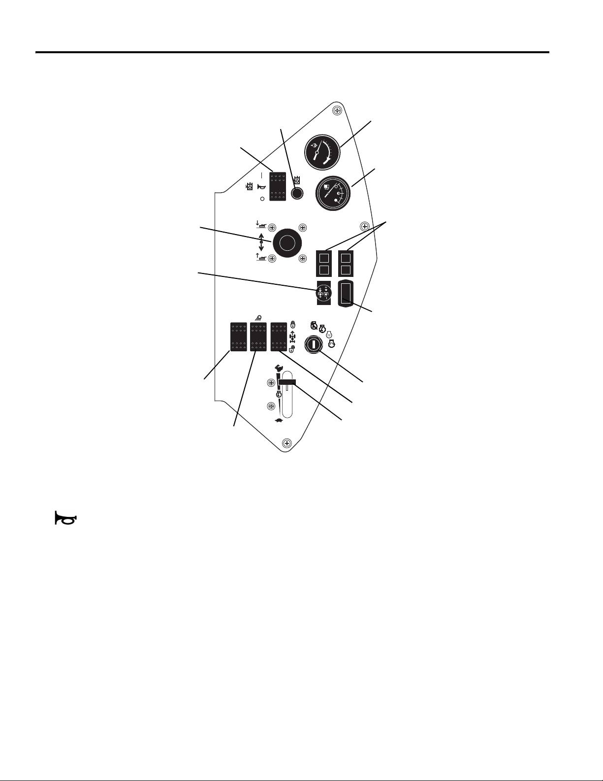
4.2 SÄÄTIMET _______________________________________________________________
A Kallistussäädin
B1 Seisontajarrun lukituskytkin
B2 Seisontajarrun
vapautuskytkin
C Seisontajarru
D Leikkuunopeuden rajoitin
E Eteenpäinajo (vetopoljin)
F Peruutus (vetopoljin)
G
Istuimen säädin
H Hydrauliöljysäiliön korkki/
öljytikku
I Polttoainesäiliön korkki
J Ilmanpuhdistimen
merkkivalo
K (ei käytössä)
L Hälytin
B
1
C
B
2
M
Valotaulu ja sulakkeet
N Hydrauliöljyn merkkivalo
O Öl jytason testauskytkin
P
Leikkurin nostovipu
Q PTO-kytkin
R Vetoluistonesto
S Valokytkin
T Moottorin pyörintänopeus
U Vakionopeudensäädin
(lisävaruste)
V Virtalukko
W Tuntimittari
X Polttoainemittari
Y Varoitusvalot
Z Lämpömittari
D
F
E
P
Q
R
O
S
N
Z
X
Y
W
V
U
T
FI-8
A
L
G
I
H
M
J
Page 27

SÄÄTIMET 4
!
!
A. Kallistussäädin
Vapauta ohjauspylväs vetämällä säädintä ylöspäin.
Säädä ohjauspylväs haluamaasi asentoon ja lukitse
paikalleen vapauttamalla säädi
VAARA: Älä koskaan säädä ohjauspylvästä
traktorin ollessa liikkeessä. Pysäytä laite ja
kytke seisontajarru ennen säätämistä.
B. Seisontajarrun lukitus- ja vapautuskytkin
Jos haluat kytkeä seisontajarrun, pidä jarrupoljinta (C)
painettuna ja paina lukituskytkintä (B
kytkeytyy päälle. Jos haluat vapauttaa seisontajarrun,
paina seisontajarrun vapautuskytkintä (B
Huomaa: Moottori sammuu automaattisesti, jos
vetopoljinta pidetään painettuna yli kymmenen sekuntia
seisontajarrun ollessa kytkettynä.
), kunnes se
1
).
2
C. Seisontajarru
Kytke seisontajarru painamalla poljinta.
D. Leikkuunopeuden rajoitin
Rajoittaa eteenpäinajonopeutta leikattaessa. Jos haluat
hidastaa ajonopeutta, käännä vipua siten, että se
koskettaa lattiassa olevaa rajoitusruuvia (D
eteenpäinajopoljinta painetaan. Jos haluat käyttää
täyttä nopeutta, aseta kytkin kuvassa olevaan asentoon
). Voit määrittää haluamasi ajonopeudet rajoitus-
(D
3
ruuvia (D
varaosaoppaassa.
) säätämällä. Lisätietoja on huolto- ja
2
D
D
3
D
2
1
E
F
Kuljetusnopeus
Leikkuunopeus
), kun
1
LF002
Kuva 4A
H. Hydrauliöljysäiliön kork ki/öljyti kku
Kaada puhdasta hydrauliöljyä öljytikussa olevaan
merkkiin asti moottorin ollessa viileä. Älä täytä säiliötä
liian täyteen.
I. Polttoainesäiliön korkki
Kaada polttoainesäiliöön luokan 2 dieselpolttoainetta,
jonka setaaniluku on vähintään 45. Lisätietoja on
kohdassa 5.11.
J. Ilmanpuhdistimen merkkivalo
Osoittaa moottorin ilmanpuhdistimen tilan. Puhdista tai
vaihda ilmanpuhdistin, kun ilmaisimen ikkunassa näkyy
punainen viiva. Lisätietoja on huolto- ja
varaosaoppaassa.
K. (Ei käytössä)
L. Hälytin
Hälytin antaa merkkiäänen ja varoitusvalot (N,Y)
syttyvät, kun jokin edellyttää käyttäjän välittömiä toimia.
Lisätietoja on kohdassa 4.4.
M. Valotaulu ja sulakkeet
V al ot aulu s ijait s ee t ak immaisen k onepellin alla käy ttäjän
istuimen takana. Siinä on neljä merkkivaloriviä, joiden
avulla voidaan seurata traktorin sähköjärjestelmää ja
selvittää siinä esiintyviä ongelmia. Lisätietoja on
huolto- ja varaosaoppaassa.
Valotaulun vieressä on neljä lattaliitinsulaketta. Voit
vaihtaa sulakkeet irrottamalla valotaulun etupaneelin.
VAARA: Sähköjärjestelmän huoltajan on
oltava koulutettu sähköteknikko. Sammuta traktori ja poista avain virtalukosta ennen
sulakkeiden vaihtamista.
N. Hydrauliöljyn merkkivalo
Varoittaa käyttäjää, jos hydrauliöljyä on liian
vähän. Valo toimii yhdessä hälyttimen
kanssa. Lisätietoja on kohdassa 4.4.
Huomaa: Varoitusvalo palaa, kunnes öljy ä on lis ätty.
Jos kuulet myös äänimerkin, voit sammuttaa sen
kääntämällä kytkimen (O) POISSA PÄÄLTÄ asentoon.
E. Eteenpäinajo (vetopoljin)
Jos haluat ajaa eteenpäin, paina polkimen etuosaa.
Hidasta vauhtia ja pysäytä traktori vapauttamalla poljin.
F. Peruutus (vetopoljin)
Jos haluat peruuttaa, paina polkimen takaosaa. Hidasta
vauhtia ja pysäytä traktori vapauttamalla poljin. Anna
traktorin pysähtyä täydellisesti ennen suunnan
vaihtamista.
G. Istuimen säädin
Siirrä istuinta eteen- tai taaksepäin vetämällä
vasemmanpuoleista vipua ulospäin. Voit säätää
istuimen jousitusta kääntämällä istuimen etupuolella
olevaa nuppia.
FI-9
Page 28
4 SÄÄTIMET
4.3 KOJETAULU______________________________________________________________
Q
P
R
O
N
Z
X
Y
W
V
S
O. Öljytason testauskytkin
Tällä kytkimellä voidaan testata hälytintä tai
sammuttaa se, kun öljyn vähäisyys on
havaittu. Pidä kytkin PÄÄLLÄ-asennossa
traktoria käynnistäessäsi ja käyttäessäsi. Jos haluat
testata hälytintä, käännä kytkin POISSA PÄÄLTÄ asentoon ja virtalukko KÄYNNISSÄ-asentoon.
Lisätietoja on kohdassa 4.4.
P. Leikkurin nostovipu
Leikkurin vipu nostaa ja laskee leikkureita. Leikkuri
toimii joko automaattisessa tai manuaalisessa tilassa.
Laske leikkurit painamalla vipua eteenpäin. Nosta
leikkureita vetämällä taaksepäin.
Manuaalinen tila - Aseta leikkuukytkin (Q)
PÄÄLTÄ
leikkurit nousevat tai laskevat, kun nostovipuun
kohdistetaan painetta.
(alas) -asentoon. Tässä asennossa kaikki
POISSA
U
T
Automaattinen tila - Aseta leikkuukytkin (Q)
(ylös) -asentoon. Automaattisessa tilassa leikkurit
laskevat ja käynnistyvät automaattisesti, kun nostovipua
siirretään hetkeksi eteenpäin. Tässä tilassa leikkurit
nousevat vain "ristileikkuun" asentoon, kun nostovipua
siirretään hetkeksi taaksepäin.
Jos haluat nostaa leikkurit kuljetusasentoon, pidä vipua,
kunnes leikkurit ovat kokonaan ylhäällä.
HUOMAA: Automaattitilan noin 3 sekuntia kestävän
nosto- tai laskujakson aikana nostovivun siirtäminen
vastakkaiseen suuntaan kytkee kaikki leikkurit pois
päältä. Manuaalinen tila käynnistyy nyt valitun asennon
kohdalla.
Q. PTO-kytkin
PTO-kytkin on kaksiasentoinen nuppikytkin, jolla
leikkurit käynnistetään ja sammutetaan. Tällä kytkimellä
asetetaan myös leikkurin nostovipu (P) käsikäyttöiseen
tai automaattiseen tilaan. Aseta leikkurikytkin
PÄÄLTÄ
(alas) asentoon, kun käynnistät traktorin.
Kuva 4B
PÄÄLLÄ
POISSA
FI-10
Page 29

R. Vetoluistonesto
Vetoluistonestojärjestelmä aktivoidaan painamalla tätä
kytkintä. Tämä järjestelmä vähentää leikkuupöytien
alapainetta lähettämällä sykäyksiä nostopiiriin, mikä
siirtää painoa traktoriin
. Alapaineen vähentäminen
parantaa vetoa, mutta voi s aa da pöy dä t nous em aan ,
mikä aiheuttaa epätasaisen leikkuujäljen. Kytkimen
valo palaa, kun järjestelmä on aktivoituna.
Vetoluistonesto poistetaan käytöstä painamalla
kytkintä uudelleen. Järjestelmän käytöstä
poistaminen voi heikentää vetoa, mutta parantaa
pöydän maakosketusta.
HUOMAA: Vetoluistonestojärjestelmä on asetettava
uudelleen, kun moottori on sammutettu.
S. Valokytkin
Säätelee työskentelyvalojen käyttöä.
T. Moottorin pyörintänopeus
Säätelee moottorin pyörintänopeutta. Käytä laitetta
täydellä kaasulla normaalikäytössä.
SÄÄTIMET 4
U. Vakionopeudensäädin (lisävaruste)
Kun säädin asetetaan PÄÄLLÄ-asentoon, vetopoljin
lukittuu senhetkiseen asentoon. Poljin vapautuu kun
säädin asetetaan POISSA PÄÄLTÄ -asentoon tai jos
seisontajarru kytketään päälle.
V. Virtalukko
Virtalukossa on kolme asentoa: POISSA PÄÄLTÄ,
KÄYNNISSÄ (PÄÄLLÄ) ja KÄYNNISTÄ. KÄYNNISSÄ
(PÄÄLLÄ) -asennossa valotauluohjelma on käytössä
sekä tulo- ja antopiirejä valvotaan. Lisätietoja on
kohdassa 5.4 sekä huolto- ja varaosaoppaassa.
W. Tuntimittari
Pitää kirjaa moottorin käyttötunneista. Tuntimittarin
avulla voit ajoittaa huoltotoimet.
X. Polttoainemittari
Osoittaa polttoaineen määrän. Tarkista polttoaineen
määrä päivittäin ennen laitteen käynnistämistä.
Y. Varoitusvalot
Syttyvät, kun jokin edellyttää käyttäjän välittömiä toimia.
Lisätietoja on kohdassa 4.4.
Z. Lämpömittari
Osoittaa jäähdytysnesteen lämpötilan.
Normaalikäytössä lämpötilan tulee olla 71-110 °C. Jos
lämpötila on yli 110 °C, laite antaa äänimerkin.
Lisätietoja on kohdassa 4.4.
FI-11
Page 30

4 SÄÄTIMET
!
!
4.4 VAROITUKSET ____________________________________________________________
Valotaulu valvoo tärkeitä laitejärjestelmiä. Se varoittaa
käyttäjää äänimerkkien ja varoitusvalojen avulla, jos jokin
edellyttää välittömiä toimia. Noudata tällaisessa tilanteessa
alla olevassa taulukossa olevia ohjeita sekä kentänhoitajan
tai huoltopäällikön määräyksiä.
Hälyttimen testaaminen:
Käännä virtalukko KÄYNNISSÄ-asentoon. Kaikki valot
palavat vähintään sekunnin ajan ja laite antaa lyhyen
äänimerkin.
Toiminto valvoo seuraavia seikkoja:
3
2
5
1
1. Hydrauliöljyn määrä.
2. Moottoriöljyn paine.
3. Jäähdytysnesteen lämpötila.
4. Hydrauliöljyn suodatin.
5. Akun varaus.
6. Jarru- ja ajopolkimen kaksoisaktivointi.
Hälytys Vaadittavat toimet
1. Hydrauliöljyn määrä - Laite
antaa äänimerkin ja hydrauliöljyn
merkkivalo syttyy. Hydrauliöljyä ei
ole riittävästi.
2. Moottoriöljyn paine - Laite
antaa äänimerkin ja öljynpaineen
merkkivalo syttyy. Öljynpaine on
liian pieni.
3. Jäähdytysnesteen lämpötila Laite antaa äänimerkin.
Jäähdytysneste on liian
lämmintä.
4
Pysäytä traktori heti, laske leikkuuyksiköt maahan ja sammuta moottori!
Tarkista ulkoisesti, ettei liitäntöjen, letkujen ja hydrauliosien ympärillä ole näkyviä
merkkejä vuodosta. Siirrä traktori huoltoalueelle huoltotoimia varten.
VAARA: Hydrauliöljyn paine on korkea. Sammuta moottori ja anna
nesteen jäähtyä, ennen kuin tarkistat nesteen määrän tai lisäät sitä.
Pysäytä traktori heti, laske leikkuuyksiköt maahan ja sammuta moottori!
Tarkista moottoriöljyn määrä. Jos merkkivalo palaa, vaikka öljyä on riittävästi,
sammuta moottori ja hinaa tai kuljeta traktori takaisin huoltoalueelle. ÄLÄ
KOSKAAN käytä moottoria, jos öljyn merkkivalo palaa, sillä tällöin moottori voi
vahingoittua vakavasti.
Pysäytä traktori heti, laske leikkuuyksiköt maahan ja sammuta moottori!
Poista jätteet, kuten lehdet ja ruohonjätteet, jotka voivat haitata ilman virtausta
konepellin säleikön kautta sekä jäähdyttimen ja öljynjäähdyttimen välissä. Jos
moottorin lämpötila on edelleen liian korkea, siirrä traktori huoltoalueelle.
VAARA: Jäähdytysnesteen paine on korkea. Sammuta moottori ja anna
nesteen jäähtyä, ennen kuin tarkistat nesteen määrän tai lisäät sitä.
LF004
Kuva 4C
4. Hydrauliöljyn suodatin Öljynsuodattimen merkkivalo
palaa.
5. Akun varaus - Merkkivalo syttyy. Siirrä traktori huoltoalueelle mahdollisimman nopeasti. Tutki akku ja
6.
Ajaminen jarru päällä - Hälytys
kuuluu.
Siirrä traktori huoltoalueelle mahdollisimman nopeasti. Vaihda hydrauliöljyn
suodattimet.
latausjärjestelmä.
Vapauta pysäköintijarru tai nosta jalka jommaltakummalta polkimelta. Jos
käyttöä jatketaan pitämällä sekä jarru- että ajopoljin, moottorin pysähtyy 10 - 60
sekunnissa riippuen polkimien käyttöjärjestyksestä.
FI-12
Page 31

KÄYTTÖ 5
!
!
5 KÄYTTÖ
5.1 PÄIVITTÄINEN TARKASTUS_________________________________________________
VAARA
Päivittäinen tarkastus tulee suorittaa vast a, kun moottori
on sammutettu ja kaikki nesteet ovat jäähtyneet. Laske
leikkurit maahan, kytke seisontajarru, sammut a moottori
ja poista virta-avain.
1. Suorita koko laitteen visuaalinen tarkastus ja etsi
kulumisjälkiä sekä irrallisia, puuttuvia tai
vahingoittuneita osia. Tarkista, ettei laitteessa ole nesteeikä öljyvuotoja ja että liitännät sekä letkut ja putket ovat
hyvässä kunnossa.
2. Tarkista polttoaineen määrä, jäähdytysnesteen taso,
kampikammion öljy ja ilmanpuhdistin. Kaikkien
nesteiden tulee olla täyden merkin kohdalla, kun
moottori on kylmä.
3. Varmista, että kaikki leikkurit on säädetty samalle
leikkauskorkeudelle.
4. Tarkista renkaiden paine.
5. Testaa varmistusjärjestelmän toimivuus.
Huomaa: Osa-ja huolto-ohjeessa on tarkemmat tiedot
huollosta, säädöistä ja huollon/voitelun kaavioista.
5.2 LUKITUSJÄRJESTELMÄ____________________________________________________
1. Lukitusjärjestelmä estää moottorin käynnistymisen,
jollei jarrupoljin ole “PAINETTUNA“, vetopoljin
“VAPAALLA“ ja kelakytkin “POISSA PÄÄLTÄ“.
Järjestelmä sammuttaa moottorin, jos käyttäjä nousee
istuimelta poistamatta kelakytkintä päältä,
vapauttamatta leikkuu- tai nostopoljinta tai kytkemättä
seisontajarrua.
● Moottori pysyy käynnissä testissä 5 tai 6.
3. Alla olevassa kaaviossa on tietoja kustakin testistä.
Kiinnitä huomiota kaaviossa oleviin merkkeihin (
Sammuta moottori testien välissä.
Testi 1: Edustaa normaaleja käynnistystoimia. Käyttäjä
istuu, seisontajarru on kytkettynä, käyttäjän jalat ovat
poissa polkimilta ja kelakytkin on “POISSA PÄÄLTÄ“.
Moottorin pitäisi käynnistyä.
9).
VAROITUS
Älä koskaan käytä laitetta, jos lukitusjärjestelmä on
poissa käytöstä tai epäkunnossa. Älä irrota tai ohita
mitään kytkintä.
Testi 2: Moottori ei saa käynnistyä, jos kelakytkin on
“PÄÄLLÄ“.
Testi 3: Moottori ei saa käynnistyä, jos seisontajarru EI
OLE KYTKETTYNÄ.
2. Varmista suorittamalla kaikki seuraavat testit, että
varmistusjärjestelmä toimii virheettömästi. Keskeytä
testi sekä tarkistuta ja korjauta järjestelmä, jos jokin
testeistä epäonnistuu alla kuvattavalla tavalla.
● Moottori ei käynnisty testissä 1;
● Moottori käynnistyy testissä 2, 3 tai 4;
Lukitusjärjestelmän tarkistaminen
Testi
1
2
3
4
5
6
Käyttäjä istuu Seisontajarru Vetopoljin
Kyllä Ei Päällä Vapaalla Kyllä Ei Päällä Pois Kyllä Ei
99 9 99
99 99 9
99999
99 9 99
99 9 9
9 9 9 9
Nouse istuimelta. Leikkuuyksikköjen on lakattava pyörimästä seitsemän (7) sekunnin kuluessa.
Testi 4: Moottori ei saa käynnistyä, jos vetopoljinta
painetaan.
Testi 5: Käynnistä moottori normaaliin tapaan, työnnä
kelakytkin PÄÄLLE ja nouse pois istuimelta.
Testi 6: Käynnistä moottori normaaliin tapaan, vapauta
seisontajarru ja nouse pois istuimelta.
Kelakytkin Moottori
vapaalla
käynnistyy
FI-13
Page 32

5 KÄYTTÖ
!
!
!
!
5.3 OHJAUSTOIMET __________________________________________________________
VAROITUS
Tämän traktorin lisävarusteisiin kuuluu ROPS-turvaohjaamo. Turvavyötä on käytettävä aina, kun traktoriin on asennettu
ROPS-turvaohjaamo. Turvavyön on oltava riittävän tiukka. Jos traktorissa ei ole ROPS-turvaohjaamoa, turvavyötä EI SAA
käyttää.
Jos traktorissa on ROPS-turvaohjaamo ja traktori uhkaa kaatua, pidä kiinni ohjauspyörästä. Älä hyppää ulos tai nous e
istuimelta.
VAARA
Voit välttää loukkaantumisen pitämällä aina suojalaseja, nahkaisia työkenkiä tai -saappaita, suojakypärää ja
kuulosuojaimia.
1. Moottoria ei koskaan saa käynnistää, jos käyttäjä ei istu
traktorissa. Älä koskaan käynnistä moottoria, jos
käyttäjä tai sivulliset ovat poistoaukon takana.
2. Älä käytä moottoria koskaan suljetussa tilassa.
3. Pidä kädet ja jalat etäällä liikkuvista osista ja
leikkuuyksiköistä. Älä tee säätöjä moottorin käydessä,
jos se on mahdollista.
4. Älä käytä traktoria tai lisälaitteita, jos niissä on irrallisia,
vahingoittuneita tai puuttuvia osia. Leikkaa ruoho
mahdollisuuksien mukaan silloin, kun se on kuivaa.
5. Tutustu traktorin ja säädinten käyttöön perusteellisesti
leikkaamalla ensin koealue.
6. Tutki leikkuualuetta, jotta voit päättää parhaan ja
turvallisimman toimintamallin. Ota huomioon ruohon
pituus, maastotyyppi ja pinnan kunto. Eri olosuhteet
edellyttävät erilaisia säätöjä tai varotoimia.
7. Älä koskaan poista leikkuujätettä suoraan
sivustakatsojia päin äläkä anna kenenkään lähestyä
laitetta sen ollessa käynnissä. Laitteen omistaja tai
käyttäjä on vastuussa sivustakatsojille tai kiinteälle
omaisuudelle aiheutuneista vahingoista.
VAARA
Poimi leikkuualueelta ennen leikkuun aloittamista kaikki
mahdolliset jätteet, kuten kivet, leikkikalut ja johdot. Siirry
uudelle alueelle varoen. Ohjaa traktoria aina sellaisella
nopeudella, että se on täysin hallinnassasi.
8. Käytä harkintaa, kun leikkaat ruohoa sora-alueiden
(kuten ajoradan, pysäköintialueen tai kulkutien) lähellä.
Traktorista lentävät kivet voivat vahingoittaa vakavasti
sivustakatsojia ja kiinteää omaisuutta.
9. Kytke kelakytkin aina off-asentoon terien
pysäyttämiseksi, kun et leikkaa.
10. Vapauta käyttölaitteiden moottorit ja nosta kelat ylös
kulku- tai ajoteitä ylittäessäsi. Pidä silmällä liikennettä.
11. Sammuta ja tarkasta laite heti, jos törmäät johonkin
esteeseen tai jos laite alkaa täristä epänormaalilla
tavalla. Korjauta laite ennen käytön jatkamista.
VAROITUS
Ennen kuin alat puhdistaa, säätää tai korjata laitetta,
vapauta kaikki käyttölaitteet, laske leikkuuyksiköt
maahan, kytke seisontajarru, sammuta moottori ja
poista virta-avain vahinkojen välttämiseksi.
12. Hidasta vauhtia ja noudata erityistä varovaisuutta, kun
ohjaat laitetta rinteessä. Lue osa 5.10. Noudata
varovaisuutta, kun olet jyrkänteiden lähellä.
13. Varmista taakse- ja alaspäin katsomalla, että tie on
vapaa, ennen kuin alat peruuttaa. Noudata
varovaisuutta, kun lähestyt mutkia, pensaita, puita tai
muita esteitä, jotka voivat häiritä näkyvyyttä.
14. Älä koskaan puhdista leikkuuosia paljain käsin. Poista
leikkuujätteet teristä harjalla. Terät ovat erittäin teräviä
ja voivat aiheuttaa vakavia vammoja.
FI-14
Page 33

KÄYTTÖ 5
!
5.4 KÄYNNISTÄMINEN ________________________________________________________
TÄRKEÄÄ: Älä käytä käynnistysnesteitä. Tällaiset
nesteet ilmanottojärjestelmässä voivat olla räjähdysherkkiä
tai aiheuttaa moottorin ryöstäytymisen ja johtaa vakaviin
vaurioihin.
VAROITUS
Istuudu istuimelle, kytke seisontajarru, aseta
vetopoljin vapaalle ja PTO-kytkin POISSA PÄÄLTÄasentoon ennen kuin yrität käynnistää moottorin,
ettet saa vammoja.
1. Istu käyttäjän istuimella, varmista, että leikkuukytkin (Q)
on POISSA PÄÄLTÄ (keskiasennossa) ja seisontajarru
kytkettynä. Nosta jalat polkimilta. Käytä aina turvavyötä,
jos traktorissa on ROPS-turvaohjaamo.
2. Väännä kaasuvipua (T) siten, että se on puoliksi auki
ja tarkista, että hälytinkytkin (O) on PÄÄLLÄ.
3. Käännä virtalukko (V) PÄÄLLE-asentoon ( ).
Huomaa: Kojetaulun varoitusvalot (N, Y) syttyvät tässä
vaiheessa. Tarkista, että valot moitteettomasti.
4. Odota, kunnes hehkutulpan merkkivalo sammuu, ja
käännä sitten virtalukko heti KÄYNNISTÄ-asentoon
( ). Vapauta se heti, kun moottori käynnistyy.
Jätä käynnistysyritysten väliin 30 sekuntia, jotta
käynnistinmoottori ehtii jäähtyä.
Kaikkien varoitusvalojen pitäisi sammua, kun moottori
on käynnistynyt.
Anna moottorin lämmetä, ennen kuin käytät sitä
suurella kierrosnopeudella.
N
O
Q
Y
V
Huomaa: Älä pidä virtalukkoa KÄYNNISTÄ-asennossa
yli kymmentä sekuntia kerrallaan. Kymmenen sekunnin
jälkeen käynnistinvirtapiiri kytkeytyy pois toiminnasta ja
se on palautettava kääntämällä virtalukko POISSA
PÄÄLTÄ -asentoon.
T
LF003
Kuva 5A
5.5 PYSÄYTTÄMINEN JA PYSÄKÖIMINEN ________________________________________
Pysäyttäminen:
Siirrä jalkasi pois vetopolkimelta.
automaattisesti, kun vetopoljin palautuu vapaalle.
aina seisontajarru, sammuta moottori ja poista avain
virtalukosta ennen kuin nouset kuljettajan istuimelta, oli syy
mikä tahansa.
Traktorin pysäköiminen normaaleissa olosuhteissa:
1. Kytke pois PTO-kytkin (Q) ja nosta ja lukitse työväline
sitten kuljetusasentoon ja poistu käyttöalueelta.
2. Valitse tasainen alue pysäköintiä varten.
a. Vapauta vetopoljin, jotta traktori pysähtyy
kokonaan.
b. Kytke irti kaikki
työvälineet maahan, kytke seisontajarru, vähennä
kaasu joutokäynnille ja anna moottorin käydä kuormittamattomana kolmesta viiteen minuuttia.
voimansiirtolaitteet, laske
Traktori jarruttaa
Kytke
Turboahdin voi vaurioitua pysyvästi, jos sen ei anneta
jäähtyä.
Estä vauriot antamalla moottorin olla tyhjäkäynnillä 3 - 5
minuutin ajan ennen moottorin sammuttamista.
3. Kytke seisontajarru, sammuta moottori ja poista avain
aina virtalukosta.
Jos syntyy hätätilanne ja traktori on pysäköitävä
käyttöalueelle, noudata alueen johtajan antamia ohjeita.
Jos traktori pysäköidään kaltevalle alustalle, pönkitä tai
kiilaa kaikki pyörät.
VAARA
FI-15
Page 34

5 KÄYTTÖ
!
5.6 AJAMINEN JA KULJETTAMINEN__________________________ ___________________
Lue kaikki tässä käyttöoppaassa olevat turvaohjeet ja
noudata niitä traktoria ajaessasi tai kuljettaessasi. Kun
peruutat, katso taaksesi ja varmista, että tie on vapaa.
Tärkeää: Jos traktoria ajetaan yleisillä teillä, sen on
täytettävä paikallisten lakien ja määräysten vaatimukset.
Lisätietoja määräyksistä ja laitetta koskevista vaatimuksista
saat paikallisilta viranomaisilta.
Leikkureiden nostaminen kuljetusasentoon:
Aseta PTO-kytkin POISSA PÄÄLTÄ-asentoon
(keskiasento). Vedä leikkurivipua taaksepäin. Pitele vipua,
kunnes leikkurit ovat ylhäällä ja nostovarret ovat ylimmässä
(kuljetus-) asennossaan.
Tärkeää: Leikkuukytkimen on oltava POISSA PÄÄLTÄ-
asennossa (keskiasento) traktorin kuljetuksen aikana.
5.7 LEIKKAAMINEN___________________________________________________________
nostaa leikkurit kuljetusasentoon, pidä vivusta, kunnes
VAROITUS
Pidä kädet, jalat ja vaatteet etäällä leikkuuyksiköstä, kun
terät liikkuvat, ettet saa vakavia vammoja.
ÄLÄ puhdista leikkuuyksiköitä KOSKAAN käsin.
Poista leikattu ruoh o teris tä har jan avul la. Terät voivat
olla teräviä ja aiheuttaa vammoja.
ÄLÄ käytä leikkureita, elleivät poistokourut tai levityslevy
ole asennettuna.
Leikkaaminen:
1. Aseta PTO-kytkin PÄÄLLÄ- (ylä-) asentoon. Tämä
toimenpide asettaa myös leikkurivivun automaattiseen
tilaan. Katso Leikkurin nostovipu -kohta sivulta 8.
2. Laske leikkurit painamalla leikkurivipua hetken
eteenpäin. Leikkurit alkavat pyöriä automaattisesti, kun
leikkuuyksiköt on laskettu.
3. Kun haluat nostaa leikkurit, vedä leikkurivipua
taaksepäin ja vapauta se. Leikkurit lakkaavat
pyörimästä ja nousevat katkaisuasentoon. Jos haluat
leikkurit ovat nousseet kokonaan.
4. Kytke luistonesto (R) tarpeen mukaan, jotta paino
jakautuu paremmin leikkuupöytien ja traktorin kesken.
[Katso 4.3]
Leikkaa aina niin, että moottori käy täydellä kaasulla.
Levityslevyn asentaminen:
Takana olevan poistokourun sijaan voidaan käyttää
lisävarusteena saatavaa levityslevyä. Älä
ellei poistokouru tai levityslevy ole asennettuna
Aseta PTO-kytkin POISSA PÄÄLTÄ- (ala-) ase ntoon,
1.
laske leikkurit maahan, kytke seisontajarru ja sammuta
moottori.
2. Irrota kolme mutteria, jotka kiinnittävät poistokourun
leikkurikoteloon.
3. Poista poistokouru ja asenna levityslevy. Kiinnitä
aiemmin irrotetut kolme mutteria. Varastoi poistokouru
turvalliseen paikkaan myöhempää käyttöä varten.
käytä leikkuria,
.
5.8 LEIKKUUNOPEUS _________________________________________________________
Leikkuutulos on parempi, jos leikkuunopeus on
huomattavasti ajonopeutta hitaampi. Tehtaassa
leikkuunopeudeksi asetetaan 10 - 11 km/t, minkä pitäisi
sopia useimpiin leikkuuoloihin. Joissakin tapauksissa
ruohon laatu voi kuitenkin edellyttää nopeuden muuttamista.
Lisätietoja on huolto- ja varaosaoppaassa.
FI-16
Page 35

KÄYTTÖ 5
!
!
5.9 HINAAMINEN JA VETÄMINEN _______________________________________________
Jos traktorissa ilmenee ongelmia ja se on sammutettava
sekä poistettava alueelta, se on nostettava kuljetusta varten
perävaunuun. Jos perävaunua ei ole käytettävissä, laitteen
voi hinata hitaasti lyhyen matkan päähän.
Noudata varovaisuutta, kun nostat traktorin perävaunuun tai
pois siitä. Kiinnitä traktori perävaunuun, jotta se ei pääsisi
liikkumaan kuljetuksen aikana.
Pitkän matkan kuljetus. Jos traktoria täytyy kuljettaa
moottoritiellä, polttoaineen sulkuventtiili on suljettava ja
renkaat on täytettävä renkaiden sivulla mainittuun
enimmäispaineeseen ennen kuin traktori kiinnitetään
traileriin. Laske rengaspaine normaaliksi sen jälkeen, kun
traktori on poistettu trailerilta. [Katso 5.9]
Avaa hinausventtiili ennen hinaamista. Hinausventtiili
mahdollistaa traktorin siirtämisen moottoria käynnistämättä
ja estää hydraulisten osien mahdollisen vahingoittumisen.
Hinausventtiili (A) sijaitsee käyttöpumpussa moottorikotelon
alla. Poista kuljettajan istuimen edessä olevalta lattialta
suojus. Avaa venttiili asettamalla nasta hinausventtiilissä
olevaan pieneen aukkoon ja käännä venttiiliä vastapäivään
enintään yhden täyden kierroksen verran.
Varmista ennen hinaamista, että leikkuuyksiköt on nostettu
ylös. Jos niitä ei voi nostaa, irrota ne traktorista.
Sulje venttiili tiukasti ja aseta kansi paikalleen hinauksen
jälkeen.
HUOMAA: Hinattaessa ei saa ylittää 3,2 km/t. Laitteen
hinaaminen pitkiä matkoja ei ole suositeltavaa.
A
LF006
Kuva 5B
5.10 RINNEKÄYTTÖ____________________________________________________________
2. Kytke luistonesto (R) tarpeen mukaan, jotta paino
VAROITUS
Jotta minimoisit kaatumisvaaran, turvallisin tapa leikata
rinteessä tai penkereellä olevaa ruohikkoa on ajaa
mäkeä ylös ja alas (pystysuorasti), ei mäen poikki
(vaakasuorasti). Vältä tarpeettomia käännöksiä, aja
hitaasti ja pidä silmällä piilossa olevia vaaratekijöitä.
VAARA
Kaatumisenestojärjestelmä (ROPS), joka on suunniteltu
erityisesti tälle traktorille, on saatavilla lisävarusteena.
Asenna ROPS ennen kuin traktoria käytetään mäissä,
joiden kaltevuus on yli 14°. Tätä traktoria ei saa
käyttää mäissä, joiden kaltevuus on yli 20°.
Traktori on suunniteltu toimimaan hyvin ja tasaisesti
normaaleissa leikkuuolosuhteissa. Noudata kuitenkin
varovaisuutta rinteissä, erityisesti epätasaisessa maastossa
ja kun ruoho on märkää. Märkä ruoho vähentää vetoa ja
ohjauksen hallittavuutta.
jakautuu paremmin leikkuupöytien ja traktorin kesken.
[Katso 4.3]
3. Jos traktorilla on tapana luistaa tai jos renkaat alkavat
jättää jälkiä ruohikkoon, siirrä traktori loivempaan
kohtaan, kunnes veto palautuu tai renkaanjälkien
muodostuminen lakkaa.
4. Jos traktori jatkaa luistamista tai jälkien jättämistä,
rinne on liian jyrkkä turvallista käyttöä varten. Älä yritä
ajaa rinnettä ylös uudestaan, vaan peruuta hitaasti
alas.
5. Kun laskeudut jyrkkää rinnettä, laske leikkuuyksiköt
aina maahan, jotta traktori ei kaatuisi helposti.
Oikea rengaspaine on erittäin tärkeä tehokkaan vedon
kannalta.
Etu ............................111 kPa
Taka.......................... 86 kPa
1. Leikkaa ruohoa aina siten, että moottori pyörii täydellä
nopeudella, mutta vähennä eteenpäinajonopeutta, jotta
oikea leikkuutiheys säilyisi.
FI-17
Page 36

5 KÄYTTÖ
!
!
!
5.11 PÄIVITTÄINEN HUOLTO ____________________________________________________
Tärkeää: Yksityiskohtaiset huolto- ja säätötiedot sekä
huolto- ja voitelukaaviot ovat huolto- ja varaosaoppaassa.
VAROITUS
1. Pysäköi traktori tasaiselle alustalle. Laske leikkuuyksiköt kokonaan maahan, kytke seisontajarru, sammuta
moottori ja poista avain virtalukosta.
2. Rasvaa ja voitele kaikki osat tarvittaessa. Vältä tulipalovaara pesemällä leikkuuyksiköt ja traktori jokaisen
käyttökerran jälkeen.
a. Älä käytä suurpaineruiskua.
b. Älä suihkuta vettä suoraan kojetauluun tai
mihinkään sähköosaan.
c. Älä suihkuta vettä jäähdytysilman ottoaukkoon tai
moottorin ilma-aukkoon.
Huomautus: Älä pe se kuumaa tai k äynnissä oleva a
moottoria. Puhdista moottori ja jäähdytinsäleikkö
paineilmalla.
d. Puhdista renkaat huolellisesti. Tarkista renga-
spaine.
e. Puhdista jäähdytin ja öljynjäähdyttimen linjat
paineilmalla (enintään 210 kPa).
3. Täytä traktorin polttoainesäiliö kunkin käyttöpäivän
jälkeen siten, että polttoaine nousee 25 mm:n päähän
täyttöputken nysästä.
Käytä uutta puhdasta luokan 2 di eselpolttoainetta, jonka
setaaniluku on vähintään 45.
4. Käsittele polttoainetta huolellisesti - se on erittäin
tulenarkaa. Käytä hyväksyttyä kanisteria. Nokan on
mahduttava polttoaineen täyttöputken nysän sisälle.
Vältä polttoaineen kaatamista ämpärin ja suppilon
avulla.
a. Älä koskaan poista polttoainesäiliön korkkia tai lisää
polttoainetta, kun moottori on käynnissä tai kuuma.
b. Älä tupakoi polttoainetta käsitellessäsi. Älä koskaan
täytä tai tyhjennä säiliötä sisätiloissa.
c. Älä koskaan täytä säiliötä liian täyteen tai anna sen
tyhjetä kokonaan. Älä läikytä polttoainetta yli. Puhdista yliläikkynyt polttoaine heti.
d. Älä koskaan käsittele tai säilytä polttoainekanisteria
lähellä avotulta tai s ellaist a lai tett a , joka v oi lähettää
kipinöitä ja sytyttää polttoaineen tai sen höyryn
palamaan.
5. Säilytä polttoainetta paikallisten määräysten ja
polttoaineen myyjän suositusten mukaisesti.
Voit välttää kuuman suuripaineisen öljyn aiheuttamat
vakavat vahingot välttämällä öljyvuotojen etsimistä
käsin. Käytä sen sijaan paperia tai pahvia.
Hydraulinen neste voi paineen alla purkautuessaan olla
riittävän voimakasta läpäistäkseen ihon. Jos nestettä
pääsee ihoon, se on poistettava muutaman tunnin
kuluessa kirurgisesti sellaisen lääkärin toimesta, joka
tuntee tämänkaltaiset vammat. Muuten tuloks ena voi ol la
kuolio.
6. Tarkasta hydrauliletkut ja -putket päivittäin. Pidä
silmällä märkiä letkuja tai öljyläikkiä ja vaihda kuluneet
tai vahingoittuneet letkut ja putket ennen laitteen
käyttöä.
VAROITUS
Älä yritä koskaan avata jäähdyttimen kantta moottorin
käydessä, ettei kuuma jäähdytysneste tai ulos
sinkoutuva höyry aiheuta vakavia ruumiinvammoja.
Sammuta moottori ja odota, kunnes se on jäähtynyt.
Noudata silloinkin äärimmäistä varovaisuutta, kun avaat
kannen.
VAARA
Älä kaada kylmää vettä kuumaan jäähdyttimeen. Älä
käytä moottoria ilman oikeaa jäähdytysaineseosta. Sulje
kansi ja kiristä se hyvin.
Kun moottori on j äähtynyt, tark ista jäähdytys nesteen
7.
määrä.
talteenottopullossa nesteen täytyy ulottua cold-
merkintään.
8. Pysäköi kone sille varattuun paikkaan. Kytke
seisontajarru ja poista avain virtalukosta. Pane avain
varmaan paikkaan, etteivät asiattomat henkilöt pääse
käyttämään laitteistoa.
9. Tarkista moottoriöljy ja hydrauliöljy aina päivän
alkajaisiksi ennen moottorin käynnistämistä. Jos öljyä
on liian vähän, poista öljyn täyttötulppa ja lisää
tarvittava määrä öljyä. Älä täytä öljysäiliötä liian
täyteen.
Jäähdyttimen tulee olla täynnä ja
FI-18
Page 37

KÄYTTÖ 5
!
!
5.12 SÄILYTYS ________________________________________________________________
Yleistä
1. Pese traktori perusteellisesti ja voitele se. Korjaa ja
maalaa uudelleen vahingoittuneet metalliosat.
2. Tarkasta traktori, kiristä kaikki osat ja vaihda kuluneet
tai vahingoittuneet osat.
Vältä loukkaantuminen ja leikkuureunojen
vahingoittuminen käsittelemällä kelaa erittäin
VAARA
huolellisesti.
3. Tyhjennä ja täytä jäähdytin uudelleen.
4. Puhdista renkaat perusteellisesti ja säilytä traktoria
siten, etteivät renkaat kuormitu. Jos traktori ei ole
tukipukeilla, tarkista renkaat säännöllisesti ja täytä ne
tarvittaessa.
5. Pidä laite ja kaikki lisävarusteet puhtaina, kuivina ja
suojattuina säilytyksen aikana. Älä koskaan säilytä
laitetta lähellä avotulta tai sellaista laitetta, joka voi
lähettää kipinöitä ja sytyttää polttoaineen tai sen
höyryn palamaan.
Akku
1. Poista ja puhdista akku sekä säilytä sitä pystyasennossa viileässä ja kuivassa paikassa.
2. Tarkista ja lataa akku uudelleen 60–90 päivän välein
säilytysaikana.
3. Säilytä akkuja kuivassa ja viileässä paikassa. Vähennä
itsepurkautumisnopeutta varmistamalla, ettei lämpötila
ylitä 27°C lämpöastetta tai -7°C alita seitsemää
pakkasastetta, jotta akkuhappo ei jäätyisi.
Moottori
1. Kun moottori on lämmin, poista tyhjennysaukon korkki,
tyhjennä öljy kampikammiosta ja vaihda öljynsuodatin.
Aseta tyhjennysaukon korkki takaisen paikalleen ja
täytä säiliö uudella öljyllä. Tyhjennystulpan
vääntömomentin tulee olla 30 Nm.
Säilytyksen jälkeen
1. Tarkista akku ja aseta se paikalleen.
2. Tarkista tai huolla polttoainesuodatin ja ilmanpuhdistin.
3. Tarkista jäähdytysnesteen taso.
4. Tarkista kampikammion ja hydraulijärjestelmän öljyn
taso.
5. Täytä polttoainesäiliö uudella polttoaineella. Tyhjennä
polttoainejärjestelmä.
6. Varmista, että renkaissa on riittävästi ilmaa.
7. Poista öljy keloista ja veitsiterästä. Säädä veitsiterä ja
leikkuukorkeus.
8. Käynnistä moottori ja käytä sitä puolella teholla. Anna
moottorin lämmetä ja tulla voidelluksi.
VAROITUS
Älä koskaan käytä moottoria ilman asianmukaista
ilmanvaihtoa. Pakokaasun hengittäminen voi olla
hengenvaarallista.
2. Puhdista moottorin ulkopinta. Korjaa vahingoittuneet
maalipinnat tai sivele ohut kerros ruosteenestoainetta.
3. Estä polttoaineen hyytyminen ja bakteerikasvuston
muodostuminen lisäämällä polttoaineeseen säilytysainetta tai eliöntorjunta-ainetta. Saat lisätietoja paikalliselta polttoainetoimittajalta.
Leikkuuyksiköt
1. Pese leikkuuyksiköt perusteellisesti ja korjaa vahingoittuneet maalipinnat.
2. Voitele kaikki osat ja hankauskohdat.
3. Sivele kelan ja veitsiterän teroitettuihin reunoihin ohut
kerros ruosteenestoainetta.
FI-19
Page 38

Page 39

Page 40

T
P
www.ttcsp.com
Equipment from Jacobsen is built to exacting
standards ensured by ISO 9001 and ISO 14001
registration at all of our manufacturing locations.
A worldwide dealer network and factory trained
technicians backed by Textron Parts Xpress
provide reliable, high-quality product support.
extron Golf, Turf & Specialty Products
O Box 7708, Charlotte, NC 28241-7708
 Loading...