

Page 1
®
BUNTON
Setup, Parts and Maintenance Manual
Manuel de maintenance et de piéces de montage
EC Hydro Midsize
Model: 930024 - Engine type: kawasaki FH451V
GBGB
GB
GBGB
WARNING: If incorrectly used this machine can cause severe injury. Those who use and maintain this machine should
be trained in its proper use, warned of its dangers and should
read the entire manual before attempting to set up, operate,
adjust or service the machine.
AVERTISSEMENT : Risque de blessures graves en cas
d’utilisation incorrecte de la machine. Les opérateurs et le
personnel d’entretien doivent être formés et conscients des
dangers encourus. Ils doivent lire avec attention le manuel
avant d’essayer de monter, d’utiliser, de régler ou maintenir
la machine.
FF
F
FF
BUNTON
Part No. 24514G (rev.0)(RJ 100 012002)
Page 2

© 2002, Textron Inc. All Rights Reserved
Page 3

EC
CONTENTS
Hydro
Midsize
IMPORTANT MESSAGE
Thank you for purchasing this Bunton product. You have purchased a world class mowing product, one of the best
designed and built anywhere.
This machine comes with an Operation and Safety Manual and a separate Setup, Parts and Maintenance Manual.
The useful life and good service you receive from this machine depends to a large extent on how well you read
and understand these manuals. Treat your machine properly, lubricate and adjust it as instructed, and it will give
you many years of reliable service.
Your safe use of this Bunton product is one of our prime design objectives. Many safety features are built in, but
we also rely on your good sense and care to achieve accident-free operation. For best protection, study the
manuals thoroughly. Learn the proper operation of all controls. Observe all safety precautions. Follow all
instructions and warnings completely. Do not remove or defeat any safety features. Make sure those who operate
this machine are as well informed and careful in its use as you are.
See a Bunton dealer for any service or parts needed. Bunton service ensures that you continue to receive the
best results possible from Bunton’ products. You can trust Bunton replacement parts because they are
manufactured with the same high precision and quality as the original parts.
Bunton designs and builds its equipment to serve many years in a safe and productive manner. For longest life,
use this machine only as directed in the manuals, keep it in good repair and follow safety warnings and instructions.
You'll always be glad you did.
T extron Golf, T urf & Specialty Products
Central Avenue, Ransomes Europark
Ipswich, England, IP3 9QG
T ABLE OF CONTENTS FIGURES PAGE
SAFETY ......................................................................................................................................................... 2
ASSEMBLY/SET-UP INSTRUCTIONS...................................................................................................... 3-12
LUBRICATION ....................................................................................................................................... 13, 14
MAINTENANCE ...................................................................................................................................... 15-17
SERVICE CHART ........................................................................................................................................ 18
SERVICE RECORD ..................................................................................................................................... 19
ADJUSTMENTS...................................................................................................................................... 20-23
BELT REPLACEMENT................................................................................................................................. 24
PARTS SECTION......................................................................................................................................... 25
UPPER ENGINE DECK ASSY ........................... FIGURE 1.................................................................. 26, 27
LOWER ENGINE DECK ASSY/CLUTCH........... FIGURE 2.................................................................. 28, 29
DRIVE WHEELS ................................................ FIGURE 3.................................................................. 30, 31
P ARKING BRAKE .............................................. FIGURE 4.................................................................. 32, 33
ELECTRIC ST A RT UPPER HANDLE................. FIGURE 5.................................................................. 34, 35
TRACTION CONTROLS .................................... FIGURE 6.................................................................. 36, 37
ELECTRIC START BATTERY............................ FIGURE 7.................................................................. 38, 39
HYDRAULICS .................................................... FIGURE 8.................................................................. 40, 41
DECALS ............................................................. FIGURE 9.................................................................. 42, 43
HYROGEAR PUMP............................................ FIGURE 10................................................................ 44, 45
CUTTERDECK MOUNTING .............................. FIGURE 11................................................................ 46, 47
ELECTRICAL DIAGRAM.................................... FIGURE 12................................................................ 48, 49
ELECTRICAL SCHEMA TIC................................ FIGURE 13...................................................................... 50
11-2001-TGTSP
GB-1
Page 4
SAFETY
EC
Hydro
Midsize
NOTICE !!!
Unauthorized modifications may present extreme
safety hazards to operators and bystanders and
could also result in product damage.
Textron Golf, Turf & Specialty Products strongly
warns against, rejects and disclaims any modifications, add-on accessories or product alterations that
are not designed, developed, tested and approved
by Textron Golf, Turf & Specialty Products Engineering Department. Any Textron Golf, Turf & Specialty
Products product that is altered, modified or changed
in any manner not specifically authorized after original manufacture–including the addition of “aftermarket” accessories or component parts not specifically approved by Textron Golf, Turf & Specialty
Products–will result in the Textron Golf, Turf & Specialty Products Warranty being voided.
Any and all liability for personal injury and/or property
damage caused by any unauthorized modifications,
add-on accessories or products not approved by
Textron Golf, Turf & Specialty Products will be considered the responsibility of the individual(s) or company designing and/or making such changes. Textron
Golf, Turf & Specialty Products will vigorously pursue
full indemnification and costs from any party responsible for such unauthorized post-manufacture modifications and/or accessories should personal injury
and/or property damage result.
This symbol means:
ATTENTION!
BECOME ALERT!
Your safety and the safety of others is involved.
Signal word definitions:
The signal words below are used to identify levels of
hazard seriousness. These words appear in this
manual and on the safety labels attached to Textron
Golf, Turf & Specialty Products machines. For your
safety and the safety of others, read and follow the
information given with these signal words and/or the
symbol shown above.
DANGER indicates an imminently hazardous
situation which, if not avoided, WILL result in death
or serious injury.
WARNING indicates a potentially hazardous situation
which, if not avoided, COULD result in death or
serious injury.
CAUTION indicates a potentially hazardous situation
which, if not avoided, MAY result in minor or moderate
injury. It may also be used to alert against unsafe
practices or property damage.
GB-2
CAUTION used without the safety alert symbol
indicates a potentially hazardous situation which, if
not avoided, MAY result in property damage
MODEL NUMBER: This number appears on
sales literature, technical manuals and price lists.
SERIAL NUMBER: This number appears only
on your mower. It contains the model number
followed consecutively by the serial number. Use
this number when ordering parts or seeking
warranty information.
SERIAL TAG
Page 5
EC
ASSEMBLY/SET-UP INSTRUCTIONS
Hydro
Midsize
GENERAL NOTE: FRONT, REAR, RIGHT HAND AND LEFT HAND REFERENCES BELOW
ARE WITH RESPECT TO AN OPERATOR AT THE CONTROLS.
1. UNCRATE - Place both power unit and cutterdeck crates on a level surface. Remove sides and top from
both the power unit and cutterdeck crates.
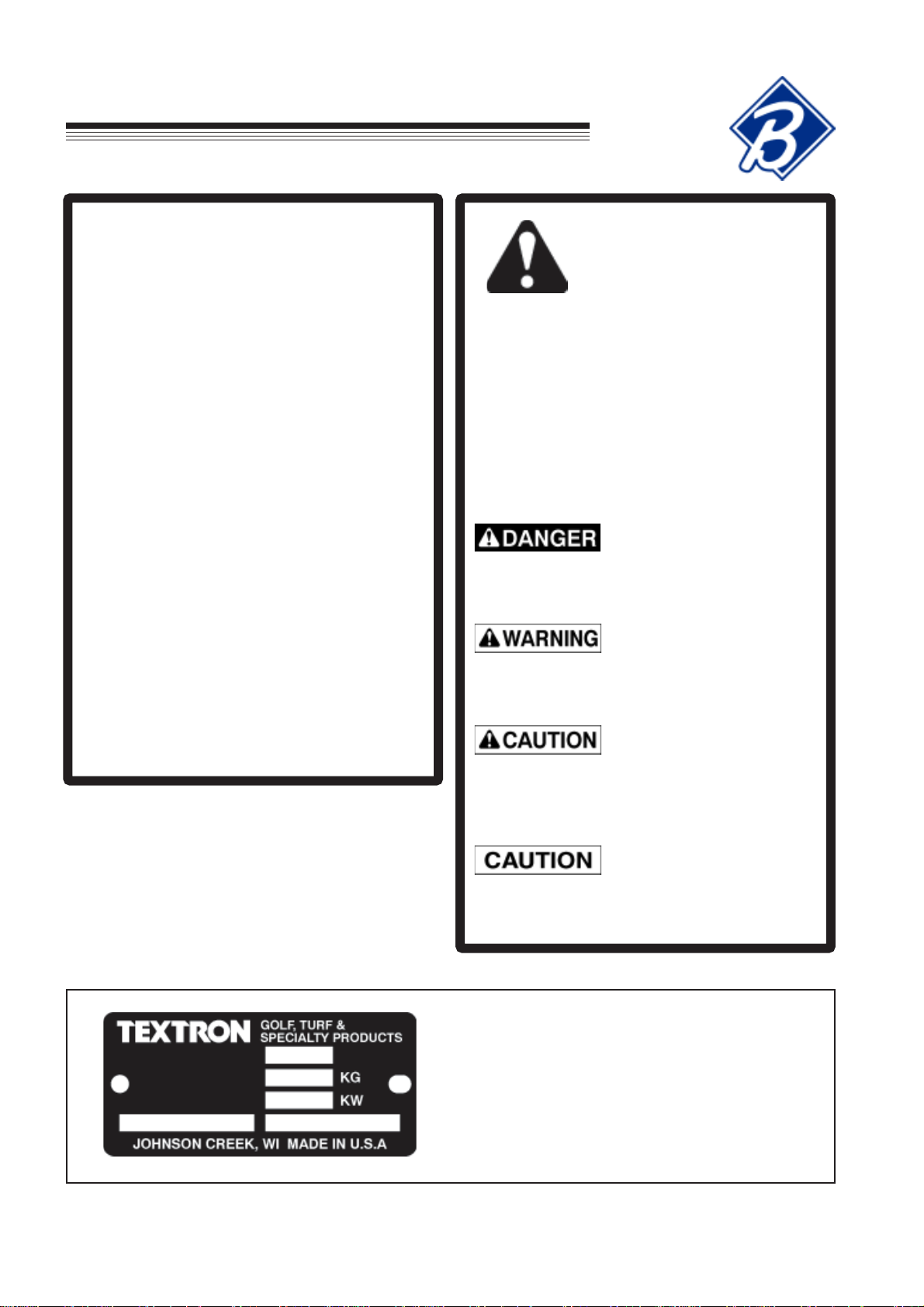
2. Remove three rods W on left and two rods W on
the right from the upper handle shipping bracket
and set them aside for later use.
3. Remove spring from bolt A. Repeat for other
side.
GB-3
Page 6
ASSEMBLY/SET-UP INSTRUCTIONS
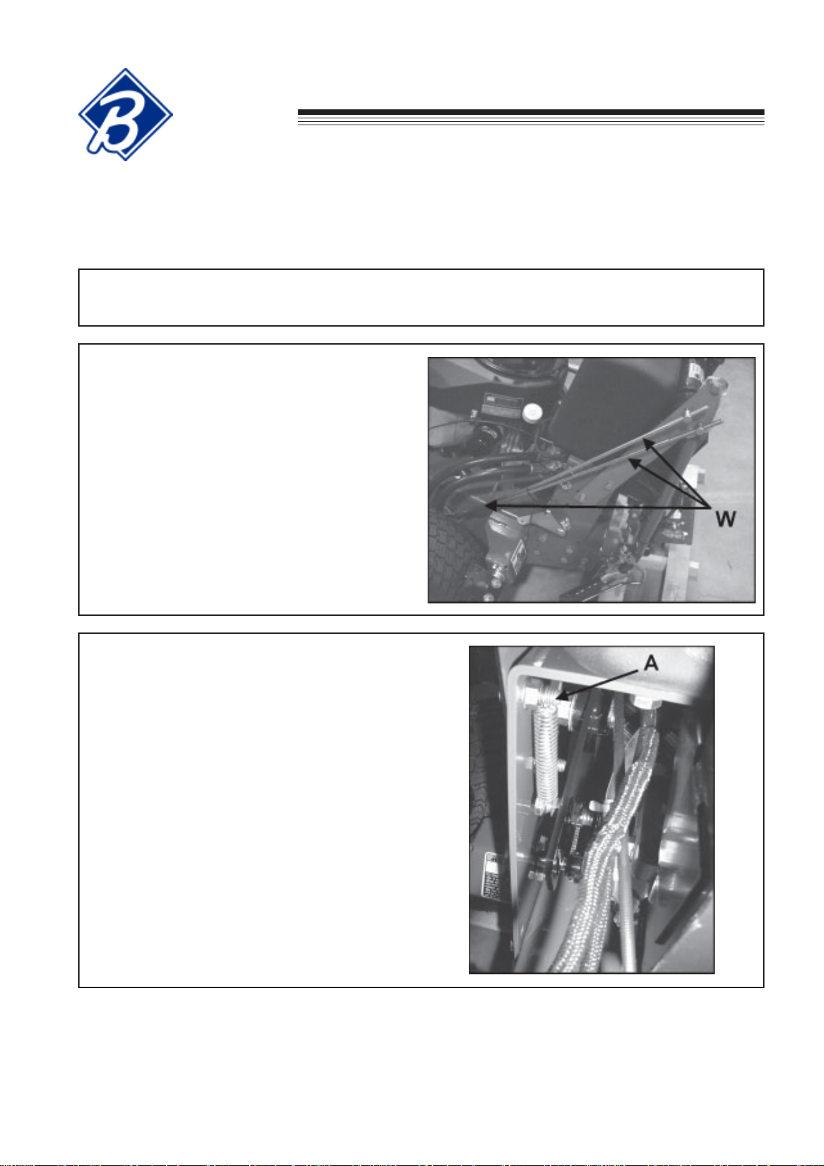
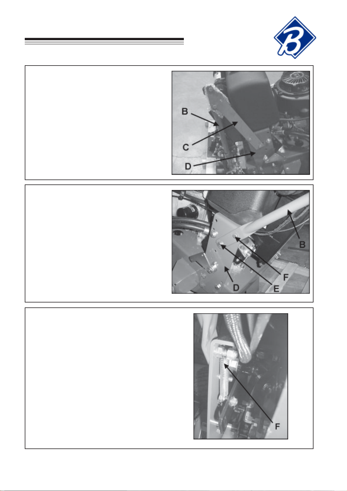
4. Unbolt upper handle B from shipping bracket C.
Unbolt shipping bracket C from lower handle D.
Retain fasteners removed for later use.
5. Bolt upper handle B to lower handle D with
(2) 3/8-16 X 1" bolts and nuts at location E bolts
removed in the previous step and
(2) 3/8-16 X 1-1/2" bolts and nuts at location F.
EC
Hydro
Midsize
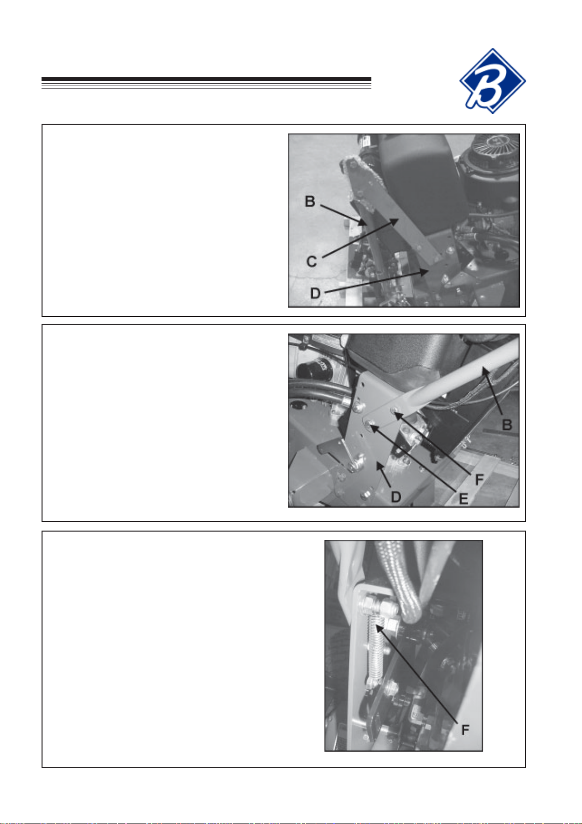
6. Reinstall spring F to bolt on both sides. Install
3/8-16 nylon locknut to end of bolt on both sides
as shown.
GB-4
Page 7
EC
Hydro
Midsize
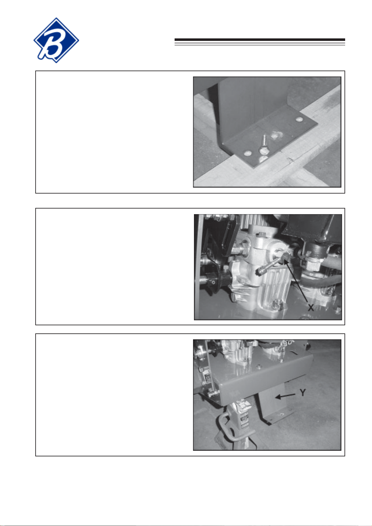
7. Unbolt shipping bracket from crate.
ASSEMBLY/SET-UP INSTRUCTIONS
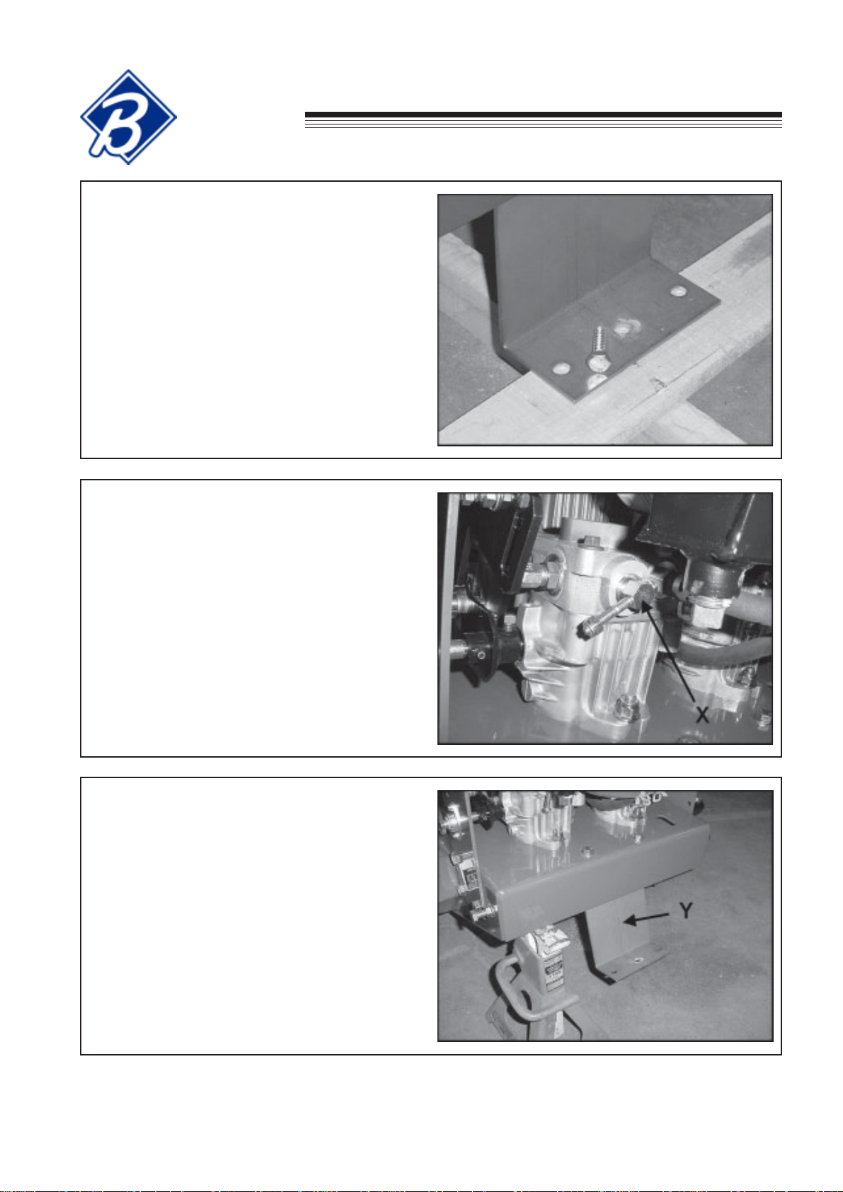
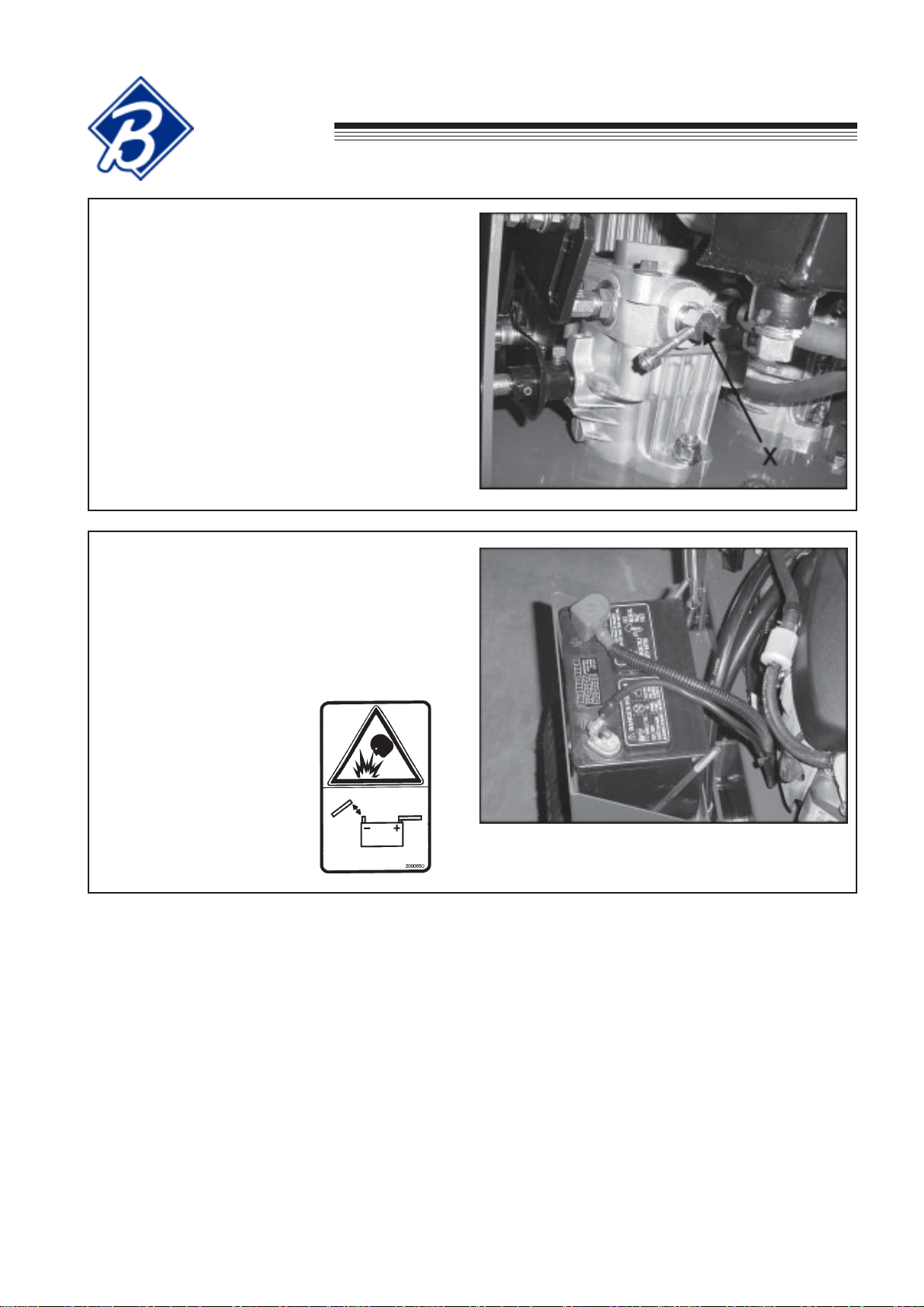
8. Open the bypass valves X on each pump by
rotating handle counter-clockwise two revolutions.
9. Remove the power unit from the crate and
support the rear of the power unit with a jack
stand.
10. Unbolt shipping bracket Y from power unit and
discard.
GB-5
Page 8
ASSEMBLY/SET-UP INSTRUCTIONS
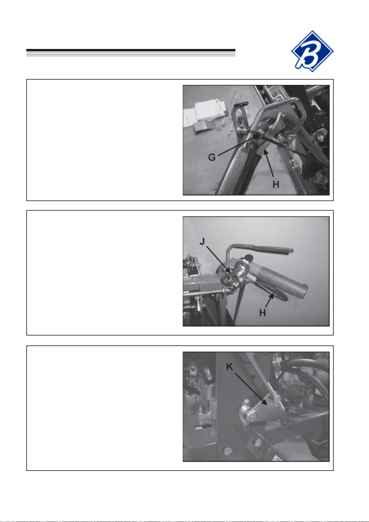
11. Cut and remove tie wrap G from the traction
control lever H.
EC
Hydro
Midsize
12. Locate the two longest rods removed in Step 2.
Install the two traction control rods through the
traction control lever H, flatwasher and traction
lock J and secure with hairpin. Repeat on other
side of upper handle.
13. With the traction locks J in the neutral position,
apply tension to the traction control rod to remove
any slack and align swivel on traction control rod
with the hole in pump arm K. Repeat for other
side.
NOTE: The pump arm has some rotational play.
Adjust the swivel on the traction control rod to the
center of this play and secure to the pump arm
with a flatwasher and hairpin as shown.
GB-6
Page 9
EC
ASSEMBLY/SET-UP INSTRUCTIONS
Hydro
Midsize
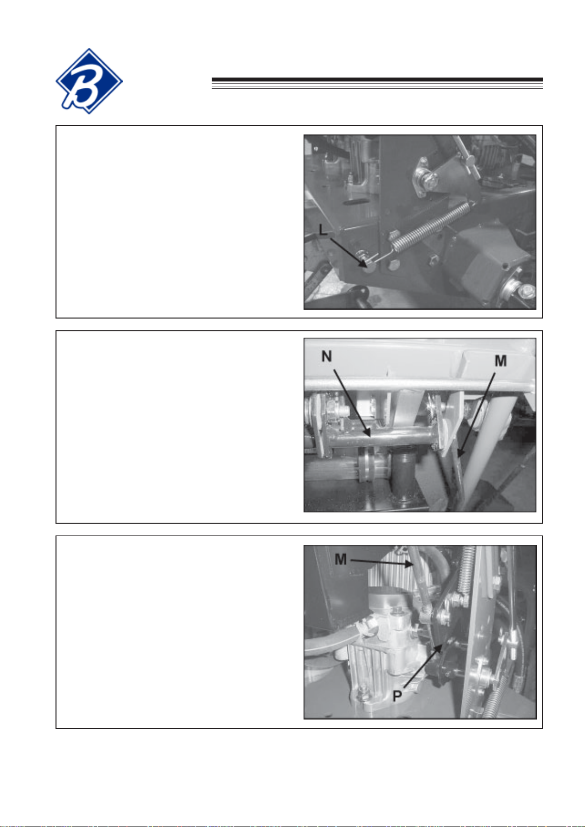
14. Attach spring to pump arm and then to bolt L.
Repeat for other side.
15. Connect speed control rod M to the speed control
levers N and secure with hairpin. Repeat for
other side.
16. Set the speed control levers to neutral and adjust
the swivel on the lower end of the speed control
rod M so they engage the very top of the slot on
the neutral plates P and secure with flatwasher
and hairpin as shown. Repeat for other side.
GB-7
Page 10
ASSEMBLY/SET-UP INSTRUCTIONS
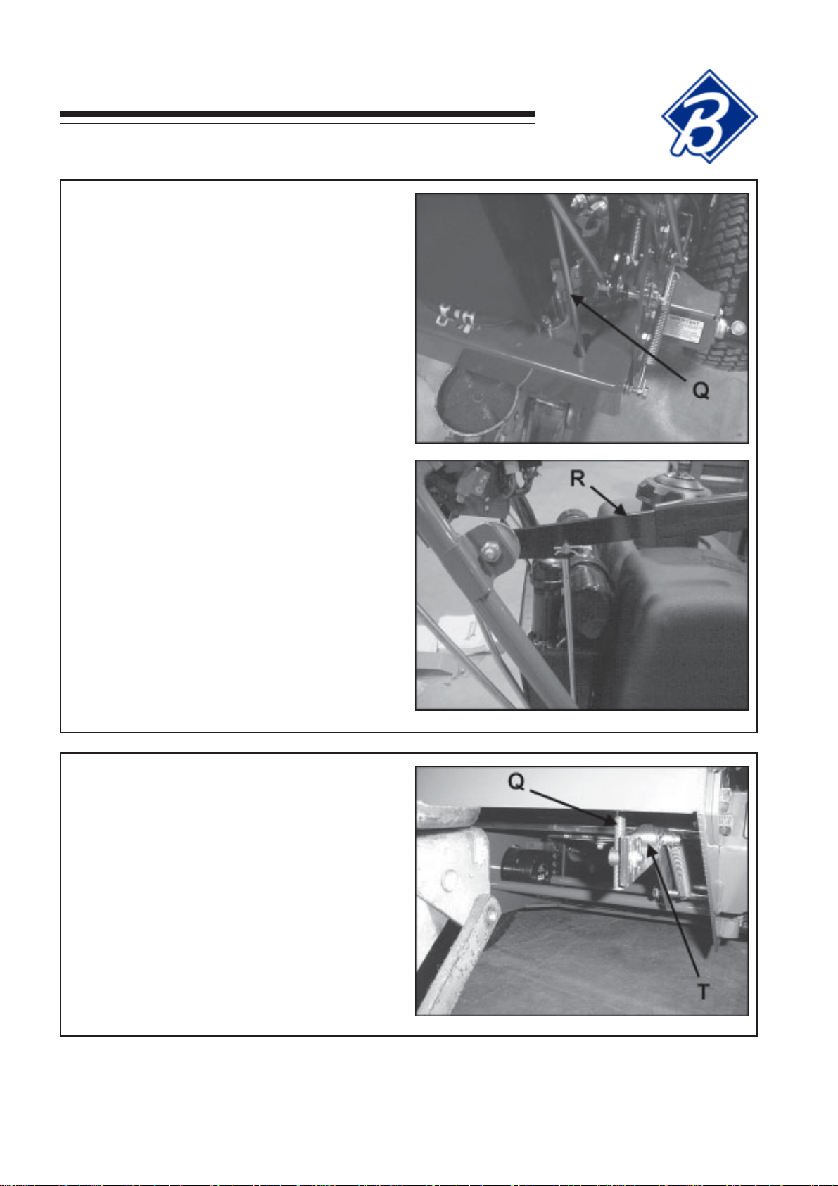
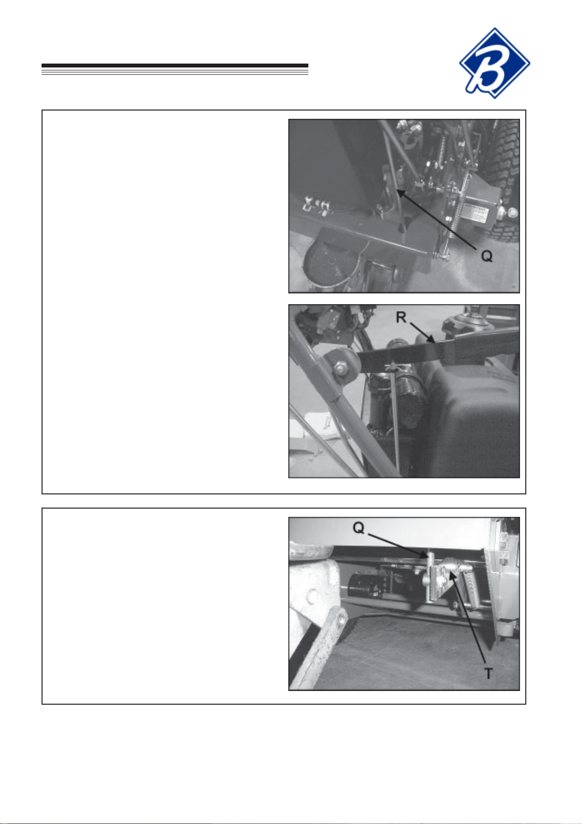
17. Insert threaded end of brake rod Q through the
slot on the engine deck and attach the other end
to the brake control arm R and secure in place
with hairpin as shown.
EC
Hydro
Midsize
18. Connect swivel on threaded end of brake rod Q to
the brake arm T and secure in place with
flatwasher and hairpin as shown. Adjust swivel to
provide adequate braking when the brake control
arm R is engaged. See adjustment section of
this manual.
GB-8
Page 11
EC
ASSEMBLY/SET-UP INSTRUCTIONS
Hydro
Midsize
19. Close bypass valve X by rotating clockwise until
firmly seated.
20. Remove the battery cover and the battery from
the machine. Fill the battery to the bottom of the
vent wells with electrolyte and trickle charge for
several hours. Replace the battery in the
machine and make the connections, red to
positive first, then black (ground) to negative.
Install battery cover and secure with previously
removed nuts.
Batteries Produce
Explosive Gases
- Keep sparks and
flame away .
- Disconnect negative
terminal first.
- Reconnect negative
terminal last.
GB-9
Page 12

ASSEMBLY/SET-UP INSTRUCTIONS
EC
Hydro
Midsize
21. Attach cutterdeck per the instructions on the following pages then return to Step 22 of this section.
22. Fill engine with oil. (See engine manual for specifications.)
23. Fill fuel tank with clean, fresh unleaded fuel.
GASOLINE IS HIGHLY FLAMMABLE!
• Fill fuel tank with good quality, clean, regular unleaded gasoline.
• Do not use hi-test fuel.
• Do not smoke.
• Do not spill fuel.
• Fill outdoors.
• Do not overfill. Fill to 25 mm below bottom of filler neck to allow room for expansion.
• USE A FUNNEL TO FILL GAS TANK
24. Check oil level in hydraulic oil reservoir and adjust as necessary.
25. Adjust tire pressure in drive wheels and casters to 1 kg/cm2.
26. Before attempting to start the mower, read and understand all sections of the Operation & Safety manual.
NOTICE: Special setup instructions.
• Before engaging the cutterdeck, run the engine for five minutes at full RPM. This is recommended for
new engine installation to permit complete engine lubrication prior to load.
• Do not engage the cutterdeck at full throttle. Set the throttle half way between the highest and lowest
engine speed, engage the PTO switch and increase the engine speed to full before cutting.
•
Do not use this machine without an approved grasscatcher, grass discharge chute or mulching plate(s)
correctly fitted.
GB-10
Page 13
EC
ASSEMBLY/SET-UP INSTRUCTIONS
Hydro
Midsize
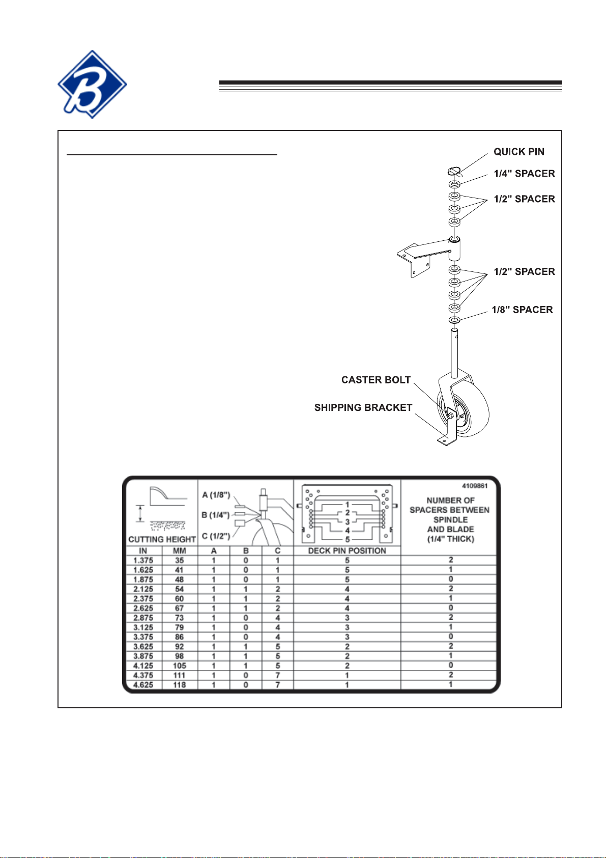
FIXED CUTTERDECK ATTACHMENT
1. Remove the cutterdeck from the crate.
2. Unbolt the caster wheels and the shipping
brackets from the crate.
3. Remove the shipping bracket from the caster
wheel by loosening the caster bolt and sliding
the shipping bracket off and retighten caster bolt.
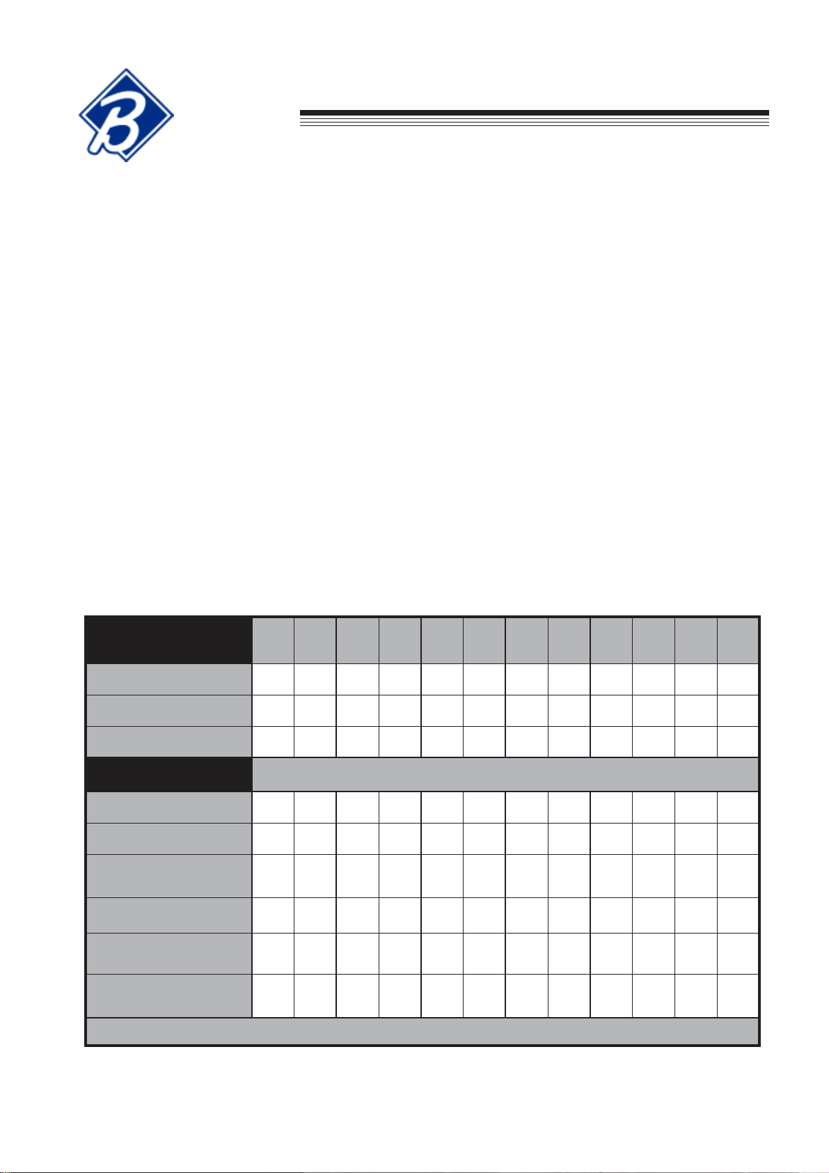
4. Remove quick pin and remove the appropriate
number of spacers for the desired height of cut.
See height of cut chart below.
NOTE: Height of cut chart is also located on
bottom of belt cover or in the Operation & Safety
Manual.
5. Repeat for other caster wheel assembly.
GB-11
Page 14
ASSEMBLY/SET-UP INSTRUCTIONS
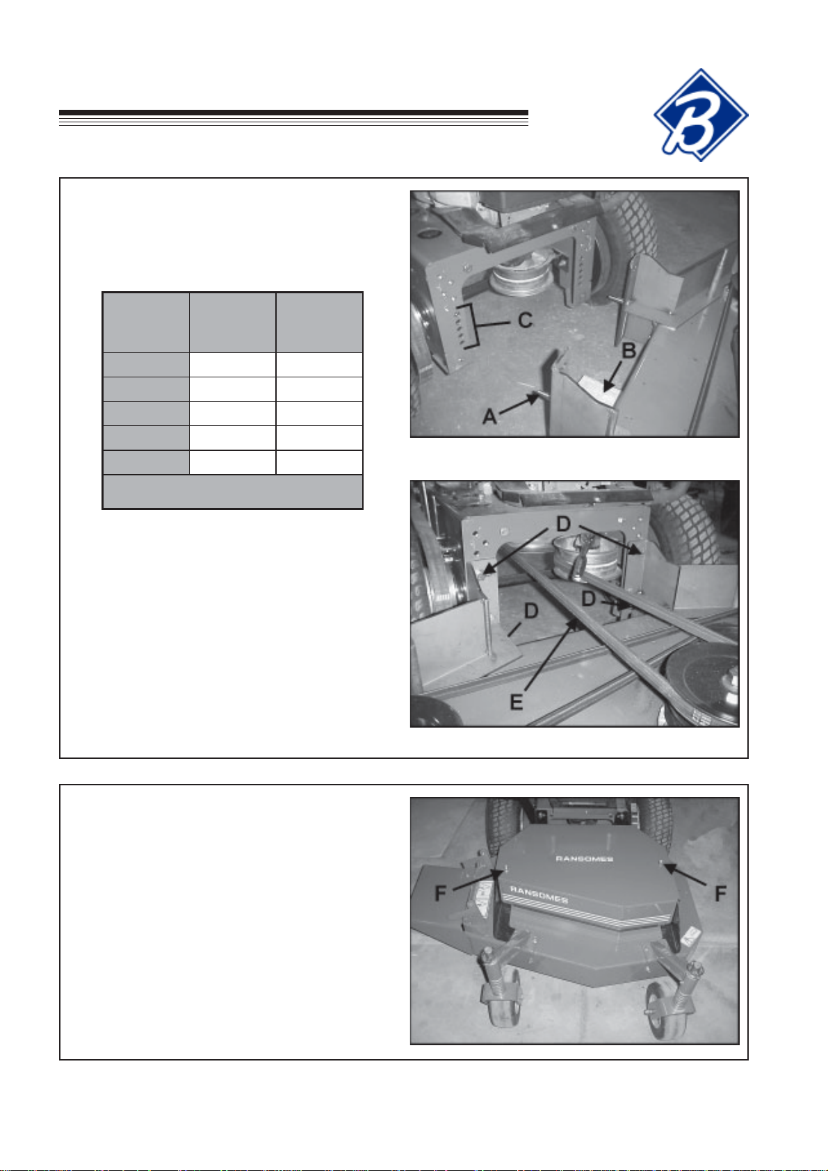
6. Remove belt cover and set aside.
7. Block the rear of the cutterdeck with the
appropriate height block for the desired height of
cut B. See Support Block Chart below.
EC
Hydro
Midsize
ELOH
GNITTUC
THGIEH
"526.1-"573.15"52.1
"573.2-"578.14"00.2
"521.3-"526.23"57.2
"578.3-"573.32"05.3
"526.4-"521.41"52.4
8. Position the power unit behind the cutterdeck.
9. Move the power unit towards the cutterdeck until
the guide pins A engage the appropriate hole C
on the power unit for the desired height of cut.
Fasten with (4) M12-1.75 X 30 bolts at D.
10. Loop the PTO belt E around the electric clutch
pulley. Using a 3/8" ratchet wrench or 3/8"
breaker bar rotate the PTO belt idler while looping
the PTO belt around the cutterdeck pulley.
NONOITISOP
ENIGNE
*KCED
.kcedenigneehtno
KCOLB
TATHGIEH
FORAER
)B(KCED
elohtsehgihehtsi1noitisoP*
11. Reinstall belt cover and fasten in place with
nuts F previously removed.
12. Remove support block from the rear of
cutterdeck.
13. Remove support from the rear of the power unit.
GB-12
Page 15
EC
LUBRICATION
Hydro
Midsize
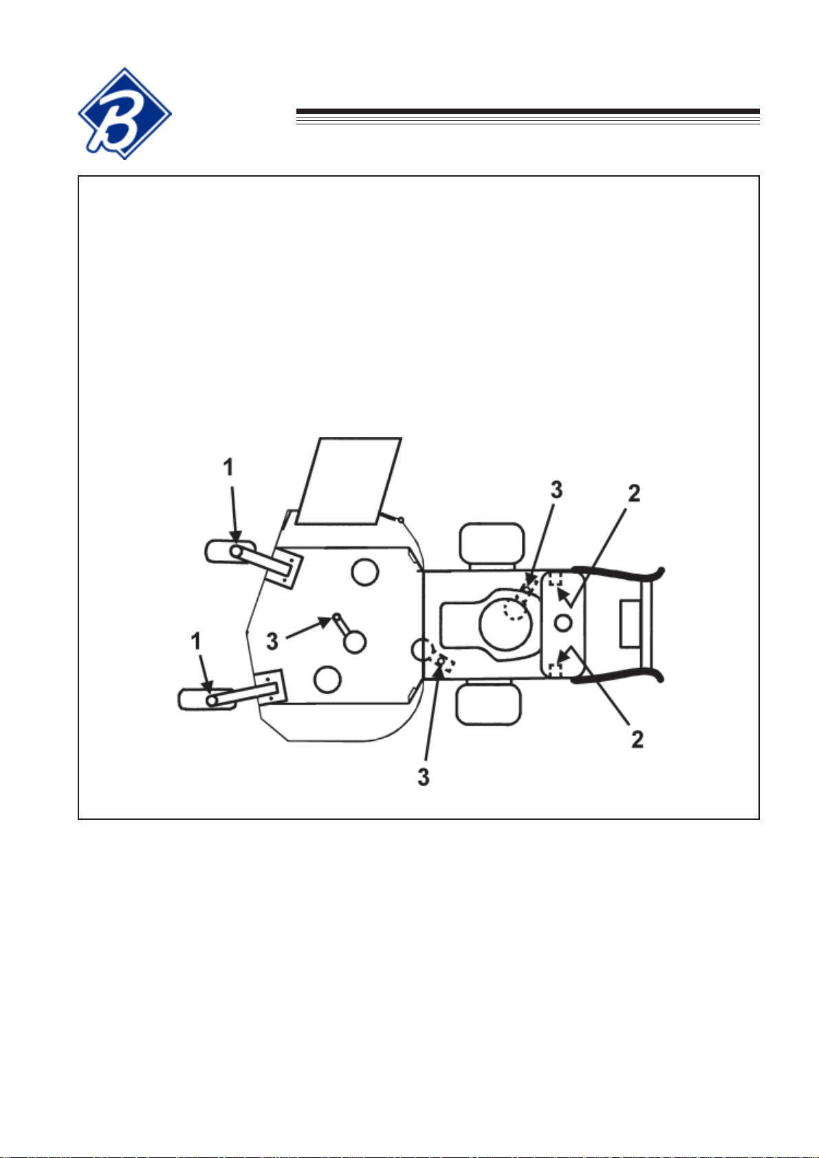
MACHINE LUBRICATION
Every 50 Working Hours - Lubricate the following points with grease:
1) Caster wheel pivots (2 points)
2) Neutral eccentric pin (2 points)
3) Idler pivot bearings:
a) Engine to cutterdeck belt tensioner
b) Cutterdeck belt tensioner
c) Hydro drive belt tensioner
NOTE: The spindles used on these machines use a superior sealed bearing which does not require
relubrication.
GB-13
Page 16
LUBRICATION
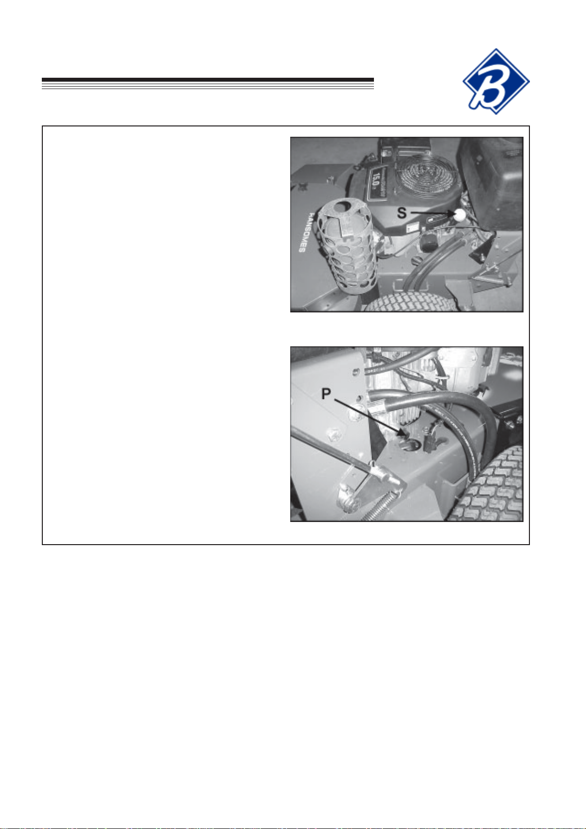
ENGINE
DAILY
Remove the dipstick S and check that the oil level
reaches the full mark. If necessary, top off with fresh oil.
To obtain the correct oil level, the machine must be
level. See engine manufacturer’s manual for proper oil
viscosity and grade.
DO NOT OVER FILL!
AFTER THE FIRST 5 WORKING HOURS
While the engine is warm, remove the drain plug P and
drain the crankcase. Replace oil filter. Clean and
replace the plug. Fill the crankcase through the filler
hole with fresh oil to the full mark. See engine manufacturers manuals for oil and filter change intervals.
Engine operator’s manuals are shipped with each
machine. Shop manuals for the engines are available
from your local engine dealer/distributor.
EC
Hydro
Midsize
• For Kawasaki FH451V, order: 99920-2129-03.
GB-14
Page 17
EC
Hydro
Midsize
The maintenance schedule detailed is for average
operating conditions. Under extreme conditions
(dusty, dirty or more than 8 hrs continuous use)
maintain more frequently.
Engine (daily)
Check the engine for oil leaks.
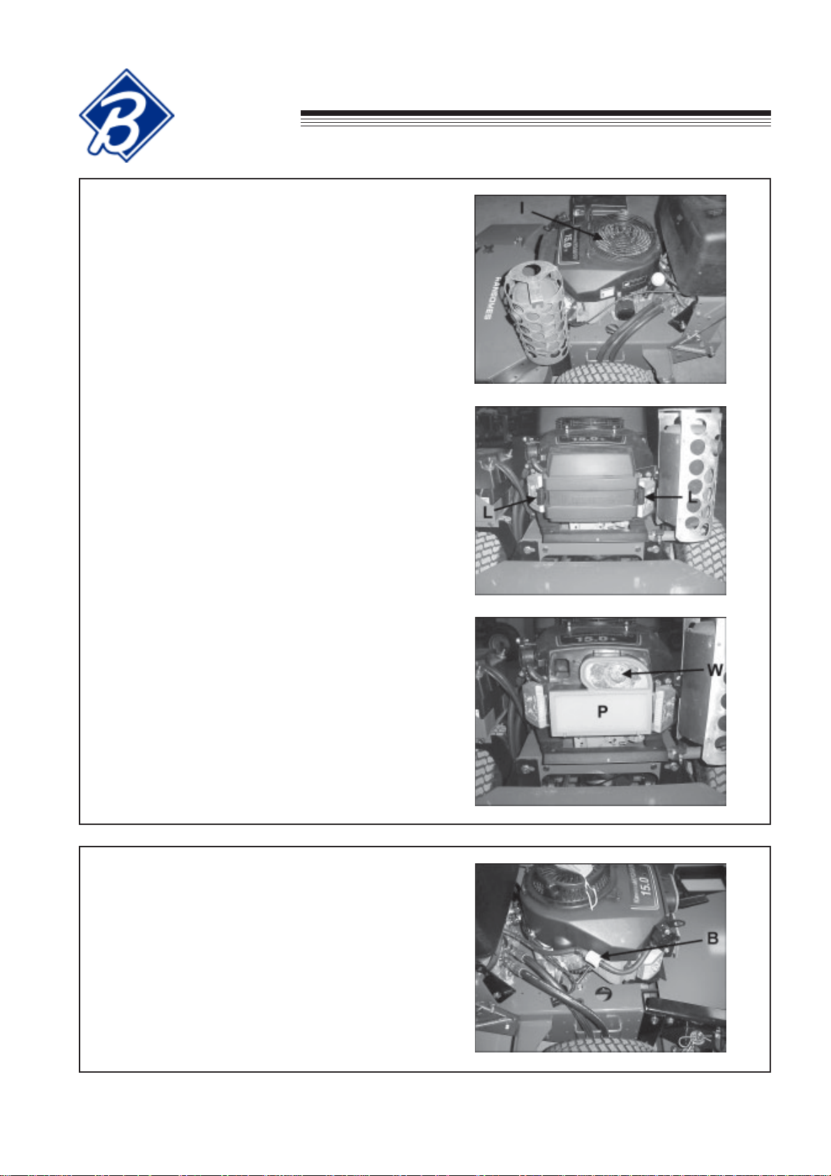
Cooling Fins and Air Intake screen (daily)
Ensure that the cooling fins and air intake screen I
are cleaned daily. Continued operation with a
clogged cooling system will cause severe overheating
and result in engine damage.
Air Cleaner (every 25 hours)
Service more frequently if operating in very dusty or
dry conditions. Extensive damage will result from
operating with a dirty air cleaner.
MAINTENANCE
1. Remove the air cleaner cover by releasing
latches L.
2. Remove the foam precleaner P by sliding it off
the paper cartridge. Wash in kerosene or
detergent and water. Dry thoroughly. Saturate in
engine oil. Squeeze to remove excess oil.
3. Reinstall all parts.
NOTES:
• Every 50 hours remove the paper element by
loosening wing nut W. If dirty, replace.
• DO NOT use petroleum solvents to clean the
paper element. They may cause it to deteriorate.
• DO NOT use pressurized air to clean or dry
element.
• See the Setup, Parts & Maintenance manual for
service part numbers.
In-Line Fuel Filter
When required, the fuel filter B may be replaced. See
the Setup, Parts & Maintenance manual for service
part numbers.
GB-15
Page 18
MAINTENANCE
EC
Hydro
Midsize
Blade Sharpening
Blades may be sharpened by filing or grinding, but with either method the balance of the blades must be
maintained at 0.004 Nm or less. Failure to maintain balance causes excess vibration, wear and shortened life
of not only the blades, but most all components of the machine. To balance a blade after sharpening: attach
3.9 g of weight 127mm from center on the light end. This should make the light end the heavy end. If it does
not: File or grind the heavy end until the addition of weight makes the light end the heavy end.
NOTE:
• Do not overheat or weaken the blades.
• Do not straighten bent blades. Replace with new
Bunton blades.
If lift portion of blade is worn thin replace with a new
Bunton blade.
• ALWAYS replace with Bunton blades—do not use
another manufacturer’s blades as this could be
dangerous.
• Replace cracked or bent blades.
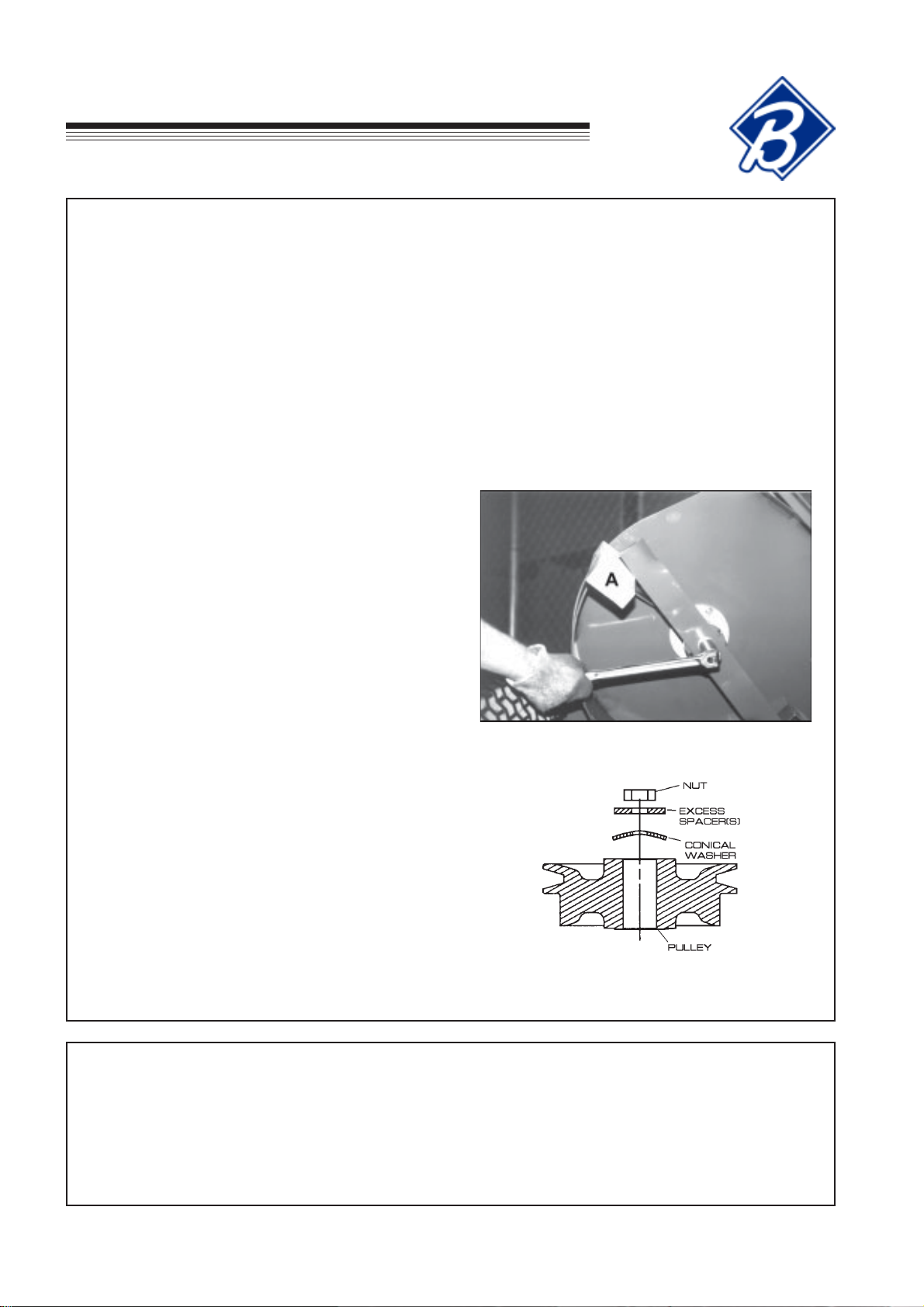
BLADE REMOVAL
1. Use a box wrench or socket with a long breaker bar
to remove spindle bolt under cutterdeck.
2. Slip tube over breaker bar or wrench if necessary to
gain leverage.
3. Keep hands clear as blades may rotate when bolt
releases.
4. When changing blades, wear thickly padded gloves.
5. Block blades from turning by using a piece of wood.
6. Follow these instructions to prevent injury when bolt
releases.
NOTE: To prevent blade from turning, place block of
wood at A, with grain perpendicular to blade.
BLADE RE-INSTALLATION
1. Place the desired number of spacers (no more than
2) on the spindle bolt below the cutterdeck between
the blade and spindle shaft.
2. Insert the cutter spindle bolt (from bottom) complete
with washer, blade and spacers.
3. Place remaining spacer(s) on the spindle bolt above
the cutterdeck between the conical washer and nut
(as shown). Replace nut and tighten to 95 Nm.
Cutterdeck Pulley Assembly
SPARK PLUG
• Remove plug and check condition.
• Good operating conditions are indicated if the plug has a light grey or tan deposit. A white blistered coating
may indicate overheating. A black coating usually means an “over rich” fuel mixture caused by a clogged
air cleaner or improper carburetor adjustment. Do not sandblast, wire brush or otherwise try to clean a
dirty plug. Best results are obtained with a new plug.
• See engine manufacturers manual for proper spark plug gap.
GB-16
Page 19
EC
Hydro
Midsize
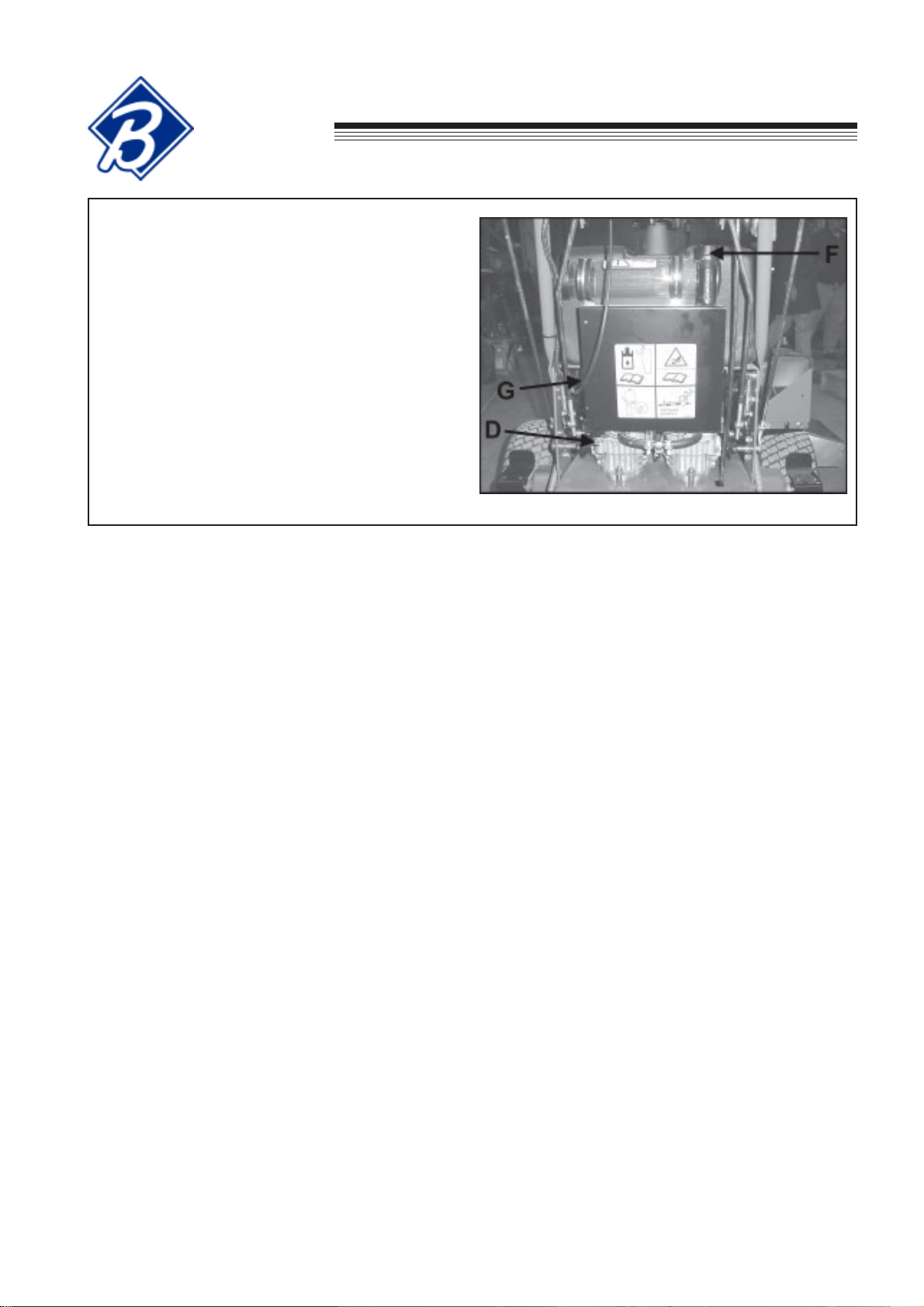
HYDRAULIC RESERVOIR
CHECK, DRAIN AND FILL
Check level every 100 hours or when a leak has
occurred. To check level: Remove reservoir cap. Add
10W30 oil until the oil level reaches the bottom of the
filler tube. Do not overfill.
EVERY 500 HOURS:
Change hydraulic oil and filter. Remove plug D to
drain reservoir. Remove and replace filter. Filter is
located on front of tank at G. Reinstall plug and fill
with 10W30 oil to the bottom of the filler tube F.
MAINTENANCE
GB-17
Page 20

SERVICE CHART
EC
Hydro
Midsize
NOTE: CHANGE ENGINE OIL AND FILTER AFTER FIRST 5 HOURS OF
OPERATION.
ECIVRES
NOITAREPO
ENIGNE
leveLliOkcehCX
riA&liOrofkcehC
skaeL
ekatnIriAnaelCX
renaelCriAnaelCX
*retliF&liOegnahCX *LAUNAMS'RERUTCAFUNAMENIGNEEES
tnemideSleuFnaelC
lwoB
tsujdA/ecalpeR
gulPkrapS
5TSRIF
SRUOH
YLIAD
X
YREVE
52
SRUOH
05
X
YREVE
SRUOH
YREVE
001
SRUOH
LAUNAMS'RERUTCAFUNAMENIGNEEES
YREVE
005
SRUOH
LIOCILUARDYH
RIOVESER
leveLliOkcehC X
ENIHCAM
eriTkcehC
serusserP
snoisneTtleBkcehC
stnioPllAetacirbuLX
X
RH2/1TSRIFRETFAKCEHC
SRH4TSRIFRETFADNA
X
Consult the manufacturer’s manual for your engine
for further information and instructions.
GB-18
Page 21
EC
SERVICE RECORD
Hydro
Midsize
NOTES
_______________________________________________________________
____________________________________________________
________________________________________________________________________
_______________________________________________________________
____________________________________________________________
____________________________________________________
________________________________________________________________________
_______________________________________________________________
____________________________________________________________
_______________________________________________________________
____________________________________________________________
_______________________________________________________________
_______________________________________________________________
LARENEG
serusserperitkcehC
stniopllaetacirbuL
stlob&stunkcehC
ENIGNE
levelliokcehC
lioegnahC
naelC
tnemelerenaelcria
snifgniloocnaelC
ETAD SRH ETAD SRH ETAD SRH ETAD SRH ETAD SRH ETAD SRH
ecalpeR
tnemelerenaelcria
pag&naelC
sgulpkraps
.sretlifdnalioenigneecalpernoitarepofosruoh5tsrifretfA:ETON
GB-19
Page 22
ADJUSTMENTS
EC
Hydro
Midsize
NOTE: Make all adjustments with the engine shut off, spark plug wire disconnected and mower
drive disengaged.
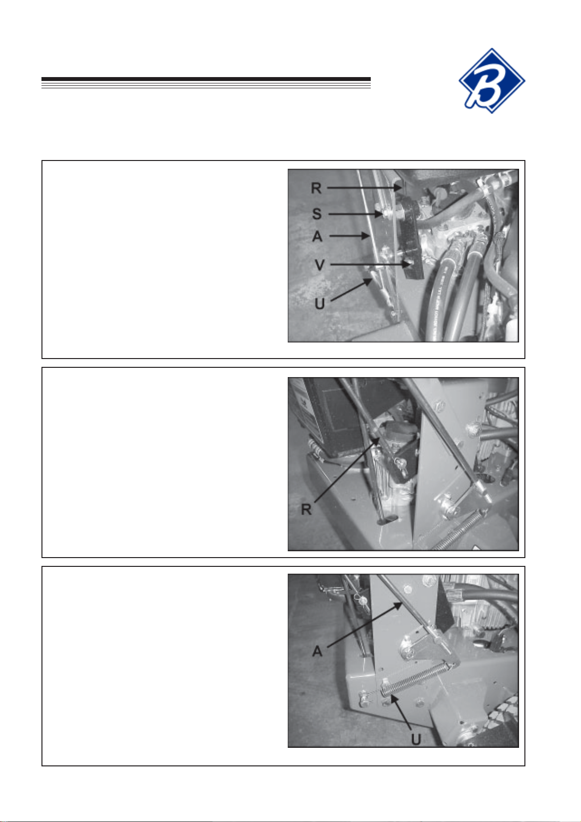
TRACTION DRIVE HYDROSTAT ADJUSTMENTS: The following adjustments must be done in order .
STEP 1 - Set Neutral
Neutral is set at the factory . If it should require
adjustment, raise the wheels off the ground by setting
the machine on jackstands or blocks. Disconnect the
traction control rod A and speed control rod R at each
pump end. Disconnect pump arm spring U from bolt
on engine deck. Loosen bolt S securing the neutral
plate eccentric shaft just enough to turn the shaft.
Start the engine and run at low speed. Turn eccentric
shaft T to raise or lower the point at which the
follower bearing is held in the center of the “V” until
the wheels stop turning. Tighten the eccentric shaft
bolt. Increase the throttle setting and check the
adjustment. Readjust if necessary . Shut the engine
off before proceeding to steps 2 and 3.
STEP 2 - Adjust Speed Control Rods
First adjust neutral, as outlined in Step 1. Set speed
control levers to neutral. Adjust swivels on lower
ends of speed control rods R so they just go into the
slots on the neutral plates.
NOTE: If the speed control levers do not have
adequate tracking adjustment, the swivel on one of
the rods needs to be turned 1 turn.
STEP 3 - Adjust Traction Levers
Set neutral and adjust speed control rods as outlined
in Steps 1 and 2. Set traction locks in the neutral
position. Grasp traction rod A and pull down on it to
take out any slack. The pump control arm has some
back and forth play . Adjust the swivel to the center of
the control arm play . Connect the swivel to the
control arm. Reattach pump arm spring U to bolt on
engine deck.
NOTE: More reverse speed may be gained by
adjusting the swivel to the rear of the control arm play .
A minimum of 1/16" play is required so the traction
controls can be put in neutral without the machine
backing up.
GB-20
Page 23
EC
Hydro
Midsize
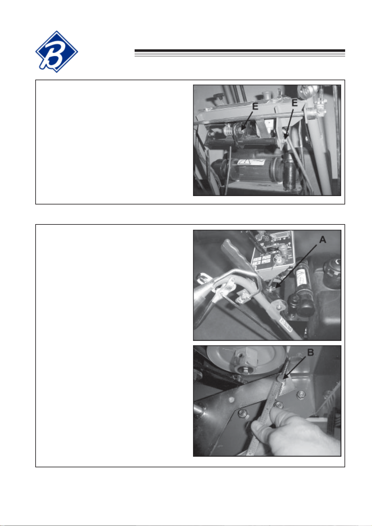
Speed Control Lever Friction
The speed control lever is held where set by friction
pads. If the setting will not hold, tighten nuts E to
increase friction on the speed control lever.
ADJUSTMENTS
PARKING BRAKE - Apply parking brakes and open
the bypass valves on the hydraulic pumps. Try to
push the machine forward. If wheels rotate, adjust
brakes as follows.
TO ADJUST:
1. Remove the hairpin cotter A from the brake rod at
the brake lever as shown.
2. Slide the brake rod out of the brake lever and turn
the rod in or out of the brake swivel B as needed.
NOTE: The brake should initially be adjusted so
that the brake rod extends through swivel B
32mm as shown. If more brake pressure is
required adjust as necessary.
3. Reassemble brake rod to the brake lever using
hairpin A.
4. Apply parking brakes and try to push the machine
forward. If wheels rotate, readjust brakes.
5. Close bypass valves on the hydraulic pumps.
GB-21
Page 24
ADJUSTMENTS
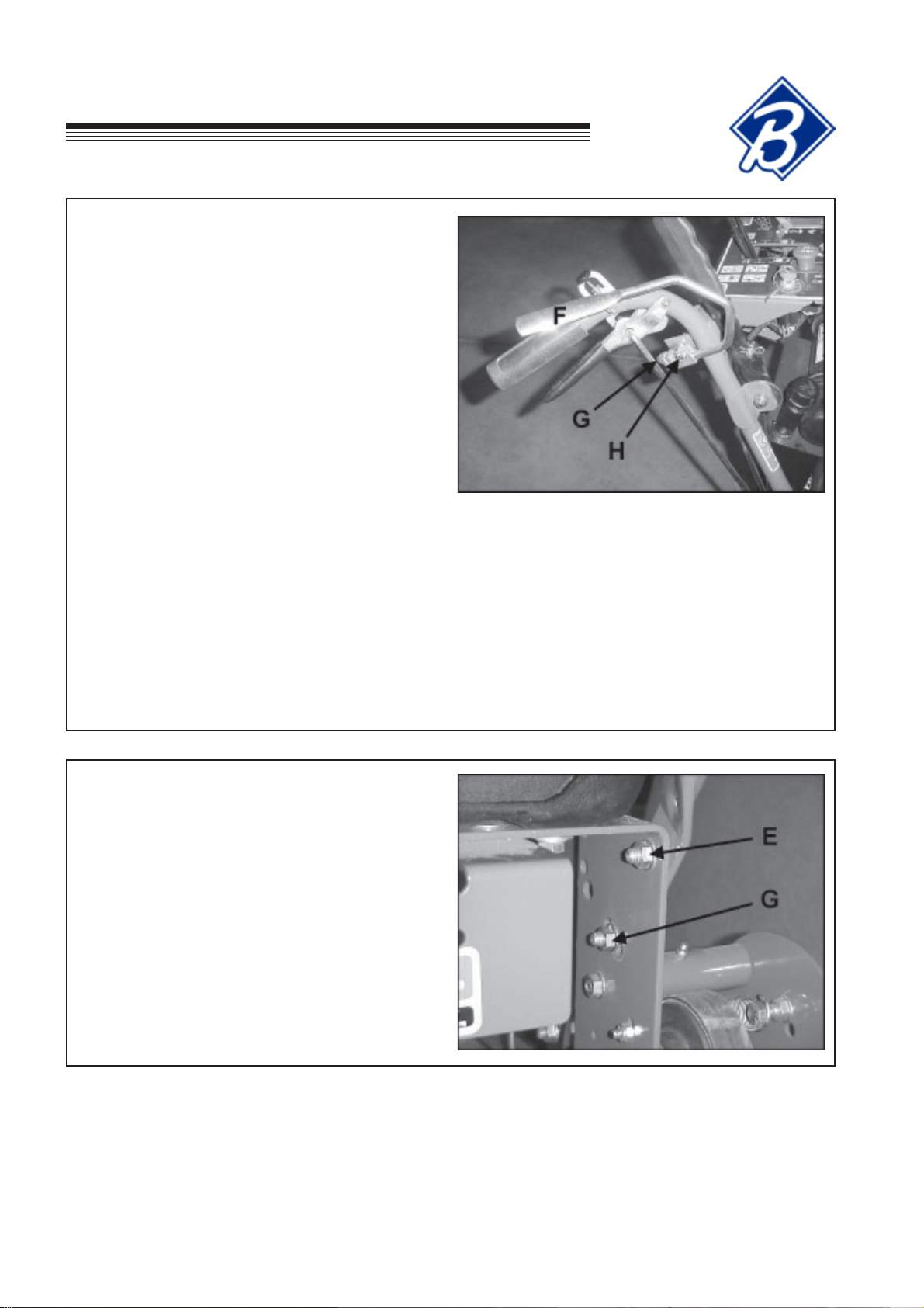
OPERATOR PRESENT CONTROLS
The operator present (OP) controls should be adjusted to control the operation of the plunger of the
operator present switch (located under the right side
of the control panel). Depressing OP levers F should
depress the plunger; releasing the levers should
extend it.
TO ADJUST:
1. Loosen clamp bolts on both ends G so clamps
can rotate on shaft. Loosen clamps bolts H so
OP levers are free to move in clamps.
2. Hold OP levers to handles and adjust to fit.
Tighten bolts H.
EC
Hydro
Midsize
3. Rotate actuator lever to depress switch plunger.
Keep OP levers against handles and tighten bolts
G.
4. When released, the OP levers should rise and the
actuator lever should rotate away from the switch,
allowing the switch plunger to extend completely.
HANDLE BAR HEIGHT ADJUSTMENT
To adjust handle bar height: Remove bolts G and
loosen bolts E on each side of handlebars. Raise or
lower as required. Reposition upper handle and
reinsert bolts G into appropriate hole in lower handle
and tighten. Readjust traction control rods, parking
brakes and speed control rods.
GB-22
Page 25

EC
Hydro
Midsize
TRACKING WIDTH ADJUSTMENT
The tracking width originally set from the factory can
be increased an additional 83 mm overall by
performing the following steps.
1. Loosen wheel lug nuts on both drive tires.
2. Raise rear of unit so that drive tires are off the
ground. Support the unit with jack stands.
3. Remove wheel lug nuts and wheels. Reattach
wheels with the tires rotated so the wheel offset is
the opposite of when they were previously
installed. Reinstall and tighten lug nuts until they
are snug.
4. Lower machine off of the jack stands and torque
wheel lug nuts to 115 Nm.
ADJUSTMENTS
TIRE PRESSURE ADJUSTMENT
Tire pressures should be maintained at 1.0 kg/cm2.
GB-23
Page 26

BELT REPLACEMENT
PTO BELT
1. Rotate idler arm using a 3/8" ratchet or breaker
bar and remove belt.
EC
Hydro
Midsize
CUTTERDECK BELT
1. Remove PTO belt.
2. Rotate idler arm using a 3/8" ratchet or breaker
bar and remove belt.
3. Replace in the reverse order.
PUMP DRIVE BELT
1. Remove PTO belt from the engine clutch.
2. Disconnect the clutch wire harness.
3. Unbolt clutch bracket from clutch and rotate the
clutch to allow enough clearance to remove the
clutch bracket.
4. Rotate idler arm using a 3/8" ratchet or breaker
bar inserted into the square hole in the idler arm.
5. Remove pump drive belt.
6. Replace by following steps in reverse order.
GB-24
View under engine deck
Page 27

MACHINE
TABLE DES MATIERES
INTERMEDIAIRE
HYDROSTATIQUE CE
CONSIGNE IMPORTANTE
Nous vous remercions d’avoir acheté une machine Bunton. Vous venez d’acquérir un produit de classe mondiale
dans le domaine des tondeuses, de la meilleure conception et construction possibles actuelles.
Cette machine est accompagnée d’un manuel de sécurité et de fonctionnement ainsi que d’un autre manuel pour
sa mise en service, ses composants et sa maintenance. La durée de vie utile et le bon état de marche dont vous
bénéficierez dépendront dans une large mesure de la façon dont vous aurez lu et assimilé ces présents. Occupezvous soigneusement de votre machine, graissez et réglez-la comme indiqué et elle vous donnera de nombreuses
années de service fiable.
Votre utilisation en toute sécurité de cette machine Bunton est pour nous l’un de nos premiers objectifs. De
nombreuses caractéristiques de sécurité sont intégrées, mais nous nous fions également à votre bon sens et à
votre soin pour la faire fonctionner sans crainte d’accidents. Pour obtenir la meilleure protection possible, veuillez
étudier attentivement les manuels. Apprenez le bon fonctionnement de toutes les commandes. Observez toutes
les précautions de sécurité. Suivez attentivement toutes les consignes et tous les avertissements. Ne démontez
aucun des dispositifs de sécurité. Assurez-vous que ceux qui font fonctionner cette machine sont bien informés
et aussi soigneux dans son utilisation que vous l’êtes vous-même.
Consultez un revendeur Bunton pour tous travaux d’après-vente ou pièces de rechange dont vous aurez besoin. Le
service après-vente Bunton veille à ce que vous continuiez de recevoir les meilleurs résultats possibles avec les
produits Bunton. Vous pouvez faire confiance aux pièces de rechange Bunton car elles sont fabriquées avec la
même haute précision et la même qualité que les pièces d’origine.
Bunton conçoit et construit ces équipements pour donner de nombreuses années de service sûr et productif. Pour
obtenir de cette machine la plus grande durée de vie possible, ne l’utilisez que comme indiqué dans les manuels,
conservez-la en bon état et suivez les avertissements et consignes car vous ne le regretterez jamais.
Textron Golf, Turf And Specialty Products
Central Avenue, Ransomes Europark
Ipswich, IP3 9QG, Angleterre
T ABLE DES MATIERES P AGE
SECURITE ...................................................................................................................................................... 2
MONT AGE / CONSIGNES D’INSTALLA TION...............................................................................................3-12
GRAISSAGE............................................................................................................................................. 13-14
MAINTENANCE ........................................................................................................................................15-17
SERVICE CHART ..........................................................................................................................................18
REGISTRE DES REVISIONS.........................................................................................................................19
REGLAGES ..............................................................................................................................................20-23
REMPLACEMENT DES CURROIES ..............................................................................................................24
11-2001-TGTSP
F-1
Page 28

SECURITE
MACHINE
INTERMEDIAIRE
HYDROSTATIQUE CE
AVERTISSEMENT !!!
Des modifications non autorisées peuvent présenter
des dangers extrêmes pour la sécurité des opérateurs
et des observateurs et elles risquent d’endommager
aussi la machine.
La Société Textron Golf, Turf And Specialty Products
rejette et décline toute responsabilité concernant toutes
modifications, accessoires ajoutés ou modifications
du produit qui ne seraient pas conçus, mis au point,
testés ni agréés par le service technique de Textron
Golf, Turf And Specialty Products. Tout produit de
Textron Golf, Turf And Specialty Products qui aurait été
altéré, modifié ou changé d’une quelconque façon qui
n’aurait pas été spécifiquement autorisée après la
fabrication d’origine - y compris l’addition d’accessoires
ou composants « d’après marché » qui ne seraient pas
spécifiquement agréés par Textron Golf, Turf And
Specialty Products - annulera automatiquement la
garantie Textron Golf, Turf And Specialty Products.
La responsabilité pour tous dommages matériels ou
corporels causés par des modifications non autorisées,
accessoires ajoutés ou non-agréés par Textron Golf,
Turf And Specialty Products sera considérée celle de
l’individu ou de la société concevant et/ou effectuant de
tels changements. Textron Golf, Turf And Specialty
Products essayera par tous les moyens d’obtenir des
dommages et intérêts de toute personne responsable
de telle modification non autorisée après la fabrication
et/ou d’accessoires ajoutés si des dommages corporels
en résultaient.
Ce symbole signifie:
ATTENTION !
PRENEZ GARDE !
Votre sécurité et celle des autres est en jeu.
Définition des avertissements:
Les avertissements ci-dessous sont utilisés pour
indiquer différents niveaux de gravité du danger. Ces
avertissements apparaissent dans le présent manuel
et sur les étiquettes de sécurité fixées sur les
machines Bunton. Pour votre sécurité et celle des
autres, veuillez lire et suivre les informations données
avec les avertissements et/ou le symbole indiqué
au-dessus.
DANGER : Indique une situation dangereuse
imminente qui, si elle n’est pas évitée, risque de
provoquer de graves blessures, voire mortelles.
AVERTISSEMENT
AVERTISSEMENT : Indique une situation
potentiellement dangereuse qui, si elle n’était pas
évitée, risque de provoquer de graves blessures,
voire mortelles.
ATTENTION
ATTENTION : Indique une situation potentiellement
dangereuse qui, si elle n’était pas évitée, risque de
provoquer un incident mineur ou modéré. Il sert
également à signaler des méthodes peu sûres ou
des dommages matériels possibles.
F-2
VIGNETTE DE SERIE
ATTENTION
ATTENTION : Utilisé sans le symbole d’alerte de
sécurité indique une situation potentiellement
dangereuse qui, si elle n’était pas évitée, risque
de provoquer des dommages matériels.
NUMERO DE MODELE : Ce numéro se trouve dans
les brochures commerciales, manuels techniques et
liste de tarifs.
NUMERO DE SERIE : Ce numéro ne se trouve que sur
la machine. Le numéro du modèle est suivi par le
numéro de série. Ce numéro doit être utilisé pour
commander des pièces de rechange ou se renseigner
à propos de la garantie.
Page 29

MONTAGE /
MACHINE
CONSIGNES D’INSTALLATION
INTERMEDIAIRE
HYDROSTATIQUE CE
REMARQUE GENERALE : L’AVANT, L’ARRIERE, LES COTES DROIT ET GAUCHE MENTIONNES
CI-DESSOUS ONT TRAIT A L’OPERATEUR SE TROUVANT AU POSTE DE CONDUITE.
1. DEBALLAGE – Placez les caisses du module de puissance et du plateau de coupe sur une surface
nivelée. Retirez les côtés et le sommet de ces caisses.
2. Déposez les trois tiges W de gauche et les deux
tiges W de droite de la patte d’attache
d’emballage du manche supérieur et mettez-les de
côté pour pouvoir les utiliser ultérieurement.
3. Déposez le ressort du boulon A. Répétez la
même procédure de l’autre côté.
F-3
Page 30
MONTAGE /
CONSIGNES D’INSTALLATION
4. Déposez le manche supérieur B de la patte
d’attache d’emballage C. Déposez la patte
d’attache C du manche inférieur D. Conservez les
attaches retirées pour pouvoir les utiliser
ultérieurement.
MACHINE
INTERMEDIAIRE
HYDROSTATIQUE CE
5. Vissez le manche supérieur B au manche inférieur
D avec deux (2) boulons et écrous
3/8-16 X 1" (E) des boulons retirés précédemment
et deux (2) boulons et écrous 3/8-16 X 1-1/2" (F).
6. Reposez le ressort F que vous fixez des deux
côtés. Placez le contre-écrou Nyloc de
3/8 - 16 des deux côtés du boulon, tel qu’illustré.
F-4
Page 31
MACHINE
INTERMEDIAIRE
HYDROSTATIQUE CE
7. Déposez la patte d’attache d’emballage de la
caisse.
MONTAGE /
CONSIGNES D’INSTALLATION
8. Ouvrez la soupape de dérivation X de la pompe en
faisant tourner le manche deux tours complets
dans le sens contraire des aiguilles d’une montre.
9. Déposez le module de puissance de la caisse et
placez un cric pour maintenir l’arrière du module.
10. Déposez la patte d’attache d’emballage Y du
module de puissance et jetez-la.
F-5
Page 32

MONTAGE /
CONSIGNES D’INSTALLATION
11. Coupez et retirez l’emballage G du levier de
commande de traction H.
MACHINE
INTERMEDIAIRE
HYDROSTATIQUE CE
12. Repérez les deux tiges les plus longues ayant été
retirées au paragraphe 2. Placez les deux tiges de
commande de traction au travers du levier de
commande de traction H, la rondelle plate et le
verrou de traction J puis fixez-les avec l’épingle à
cheveux. Répétez l’opération de l’autre côté du
manche supérieur.
13. Alors que les verrous de traction J se trouvent au
point mort, tendez la tige de commande de
traction pour éliminer toute détente et alignez la
rotule de la tige de commande à l’orifice de la
biellette de la pompe K. Répétez la procédure de
l’autre côté.
REMARQUE : La biellette de la pompe a un jeu
rotatif. Ajustez la rotule de la tige de commande
de traction au centre de ce jeu puis fixez la
biellette de la pompe avec une rondelle plate et
épingle à cheveux, tel qu’illustré.
F-6
Page 33

MACHINE
INTERMEDIAIRE
HYDROSTATIQUE CE
14. Attachez le ressort à la biellette de la pompe puis
au boulon L. Répétez la même procédure de
l’autre côté.
MONTAGE /
CONSIGNES D’INSTALLATION
15. Raccordez la tige de commande de vitesse M aux
leviers de commande de vitesse N puis fixez-la
avec une épingle à cheveux. Répétez la même
procédure de l’autre côté.
16. Placez les leviers de commande de vitesse au
point mort et ajustez la rotule du bout inférieur de
la tige de commande de vitesse M pour que les
leviers puissent s’enclencher au sommet de la
fente des plaques de point mort P puis fixez avec
une rondelle plate et épingle à cheveux, tel
qu’illustré. Répétez la même procédure de l’autre
côté.
F-7
Page 34
MONTAGE /
CONSIGNES D’INSTALLATION
17. Faites passer le bout fileté de la tige de frein Q
dans la fente située sur le plateau moteur et
attachez l’autre bout à la biellette de commande
de frein R puis fixez avec une épingle à cheveux,
tel qu’illustré.
MACHINE
INTERMEDIAIRE
HYDROSTATIQUE CE
18. Raccordez la rotule du bout fileté de la tige de
frein Q à la biellette de frein T et fixez-la avec une
rondelle plate et épingle à cheveux, tel qu’illustré.
Ajustez la rotule pour assurer un freinage adéquat
quand la biellette de commande de frein R se
serre. Reportez au chapitre intitulé “Réglages” de
ce manuel.
F-8
Page 35

MACHINE
INTERMEDIAIRE
HYDROSTATIQUE CE
19. Fermez la soupape de dérivation X en la faisant
tourner dans le sens des aiguilles d’une montre
jusqu’à ce qu’elle tienne solidement.
MONTAGE /
CONSIGNES D’INSTALLATION
20. Déposez le couvercle de la batterie et la batterie
de la machine. Remplissez la batterie d’électrolyte
puis effectuez une charge de compensation
plusieurs heures. Reposez ensuite la batterie
dans la machine et raccordez-la en branchant la
borne positive (rouge) en premier puis la borne
négative (terre). Reposez son couvercle et fixez-le
avec les écrous retirés au préalable.
Les batteries produisent des
gaz explosifs
- Eloignez-les des flammes
et étincelles.
- Débranchez, tout d’abord,
la borne négative.
- Rebranchez, en dernier,
la borne négative.
F-9
Page 36

MONTAGE /
CONSIGNES D’INSTALLATION
MACHINE
INTERMEDIAIRE
HYDROSTATIQUE CE
21. Fixez le plateau de coupe en suivant les recommandations figurant aux pages suivantes puis reportez-vous
au paragraphe 22 de ce chapitre.
22. Remplissez le moteur d’huile. (Reportez-vous au Manuel du moteur pour obtenir les spécifications).
23. Remplissez le réservoir carburant de diesel propre.
AVERTISSEMENT
LE DIESEL EST TRES INFLAMMABLE !
• Remplissez le réservoir carburant de diesel propre de bonne qualité.
• N’utilisez pas de carburant pour essais approfondis.
• Ne fumez pas.
• Ne renversez pas le carburant.
• Faites le plein à l’extérieur.
• Ne faites pas déborder. Laissez un vide de 25 mm sous le goulot de remplissage.
• IL FAUT UTILISER UN ENTONNOIR POUR REMPLIR LE RESERVOIR A GAZ.
24. Vérifiez le niveau d’huile du réservoir hydraulique et rétablissez-le, le cas échéant.
25. Ajustez la pression des roues motrices à 1 kg/cm2.
26. Il faut lire et assimiler le Manuel Opératoire et de Sécurité avant d’utiliser la machine.
REMARQUE : Consignes spéciales de mise en service
• Avant de vous servir du plateau de coupe, faites tourner cinq minutes le moteur à plein régime. Il est
recommandé d’agir ainsi car le moteur est neuf et ceci permet de le graisser avant de le charger.
• Ne mettez jamais en marche le plateau de coupe à plein régime mais placez la manette des gaz à mirégime entre le ralenti et plein régime. Utilisez l’interrupteur de la prise de force et augmentez le régime
moteur pour qu’il atteigne le plein régime avant de commencer à tondre.
•
AVERTISSEMENT
La machine ne doit pas être utilisée sans être munie d’un collecteur d’herbe agréé, d’un goulot de
déversement ou d’une (des) plaque(s) de paillage.
F-10
Page 37

MACHINE
INTERMEDIAIRE
HYDROSTATIQUE CE
MONTAGE /
CONSIGNES D’INSTALLATION
ACCESSOIRE DE PLATEAU DE COUPE
FIXE
1. Déposez le plateau de coupe de la caisse.
2. Dévissez les roues pivotantes et les pattes
d’attache d’emballage de la caisse.
3. Déposez la patte d’attache d’emballage de la roue
pivotante en desserrant son boulon et en faisant
glisser la patte d’attache pour la retirer puis en
resserrant le boulon de la roue pivotante.
4. Retirez la goupille à déclenchement instantané et
retirez le nombre d’entretoises requis pour obtenir
la hauteur désirée. A cet effet, reportez-vous au
tableau suivant.
REMARQUE : Le tableau des hauteurs de coupe
se trouve aussi en bas du carter de la courroie ou
dans le Manuel Opératoire et de Sécurité.
5. Répétez la procédure sur les autres roues
pivotantes.
GOUPILLE A
DECLENCHEMENT
INSTANTANE
ENTRETOISE 1/4”
ENTRETOISE 1/2”
ENTRETOISE 1/2”
ENTRETOISE 1/8”
BOULON DE
ROUE PIVOTANTE
PATTE D’ATTACHE
(EMBALLAGE)
HAUTEUR DE COUPE
NOMBRE
D’ENTRETOISES ENTRE
L’AXE ET LA LAME
(EPAISSEUR 0,60 CM)
POSITION DES GOUPILLES DE PLATEAU
F-11
Page 38

MONTAGE /
CONSIGNES D’INSTALLATION
6. Déposez le carter de la courroie et placez-le sur le
côté.
7. Bloquez l’arrière du plateau de coupe avec une
cale de hauteur adéquate pour obtenir la hauteur
de coupe requise B. Reportez-vous au tableau
suivant pour ce qui concerne les cales.
MACHINE
INTERMEDIAIRE
HYDROSTATIQUE CE
SEDNOITISOP
EDRUETUAH
EPUOC
60,4-mc64,3
mc
39,5-mc86,4
mc
18,7-mc65,6
mc
86,9-mc34,8
mc
,11-mc13,01
mc65
UDSECIFIRO
UAETALP
*RUETOM
5mc521,3
4mc5
3mc78,6
2mc57,8
1mc26,01
.ruetomuaetalpud
UDRUETUAH
ACOLB
EREIRRA’L
UAETALPUD
)B(
tuahsulpelecifiro’ltse1noitisoP*
8. Placez le module de puissance derrière le plateau
de coupe.
9. Avancez le module de puissance vers le plateau
de coupe pour enclencher les goupilles guides A
dans l’orifice C du module et obtenir la hauteur de
coupe requise. Serrez-les avec quatre (4) boulons
M12 – 1,75 X 30 (D).
10. Bouclez la courroie de la prise de force E autour
de la poulie d’embrayage électrique. A l’aide d’un
cliquet de 3/8" ou d’une poignée articulée de 3/8",
faites tourner la partie libre de la courroie de la
prise de force pendant que vous la bouclez autour
de la poulie du plateau de coupe.
11. Reposez le carter de la courroie et fixez-le avec
les écrous retirés au préalable.
12. Déposez le support à l’arrière du plateau de
coupe.
13. Déposez le support de l’arrière du module de
puissance.
F-12
Page 39

MACHINE
GRAISSAGE
INTERMEDIAIRE
HYDROSTATIQUE CE
GRAISSAGE DE LA MACHINE
Toutes les 50 heures d’horamètre – Graisser les points suivants :
1) Pivots de roue pivotante (2 points de graissage)
2) Goupille excentrique de point mort (2 points)
3) Roulements de pivots libres :
a) Moteur de tendeur de courroie de plateau de coupe
b) Tendeur de courroie du plateau de coupe
c) Tendeur de courroie d’entraînement hydrostatique
REMARQUE : Les axes de ces machines ont des roulements scellés de haute qualité graissés à vie.
F-13
Page 40

GRAISSAGE
MOTEUR
QUOTIDIENNEMENT
Retirez la jauge S et assurez-vous que le niveau
d’huile se trouve sur le point de repère Maxi.
Rétablissez, s’il y a lieu, le niveau avec de l’huile
propre. La machine doit être sur une surface plate pour
obtenir le niveau correct d’huile. A cet effet, reportezvous au manuel du fabricant du moteur pour obtenir la
liste des huiles recommandées.
IL NE FAUT JAMAIS FAIRE DEBORDER !
APRES LES 5 PREMIERES HEURES
D’HORAMETRE
Pendant que le moteur est chaud, retirez le bouchon
de vidange P et vidangez le carter-moteur. Remplacez
le filtre à huile. Nettoyez puis reposez le bouchon.
Remplissez le carter-moteur d’huile propre par l’orifice
de remplissage en veillant à ce que le niveau se situe
sur Maxi. Reportez-vous au manuel du fabricant du
moteur pour obtenir les intervalles de remplacement du
filtre et de l’huile.
MACHINE
INTERMEDIAIRE
HYDROSTATIQUE CE
Les machines sont toutes accompagnées d’un manuel
de l’opérateur pour ce qui concerne le moteur. Des
manuels de moteurs sont en vente chez votre
distributeur de moteurs régional.
• Pour Kawasaki FH451V, commandez : 999202129-03.
F-14
Page 41

MACHINE
INTERMEDIAIRE
HYDROSTATIQUE CE
Le programme de maintenance est destiné à des
conditions de fonctionnement moyennes. En cas de
conditions extrêmes (poussières, saletés ou plus de 8 h
d’utilisation continue), rapprochez les intervalles de
maintenance.
Moteur (quotidiennement)
Vérifiez l’absence de fuites d’huile du moteur.
Ailettes de refroidissement et tamis d’admission d’air
(quotidiennement)
Veillez à ce que les ailettes de refroidissement et le tamis
d’admission d’air I soient nettoyés quotidiennement. Un
fonctionnement continu de la machine contribue à bloquer
le circuit de refroidissement ce qui provoque la surchauffe
du moteur et l’endommage éventuellement.
Epurateur d’air (toutes les 25 heures)
Rapprochez ses intervalles de maintenance s’il est
soumis a beaucoup de poussières ou un environnement
très sec. Risque d’endommagement important quand
l’épurateur d’air est sale.
MAINTENANCE
1. Déposez le couvercle de l’épurateur d’air en
desserrant les attaches L.
2. Déposez le prénettoyeur de mousse P en le faisant
glisser de la cartouche en papier. Nettoyez-le avec du
kérosène ou un détergent et de l’eau. Séchez-le
ensuite à fond. Trempez-le ensuite dans de l’huile
moteur puis tordez-le pour éliminer l’excès d’huile.
3. Reposez toutes les pièces.
REMARQUES :
• Toutes les 50 heures d’horamètre, desserrez l’écrou à
oreilles W pour retirer l’élément en papier.
• IL NE FAUT PAS utiliser de produits de nettoyage à
base de vaseline pour nettoyer l’élément en papier car
ils risquent de l’endommager.
• IL NE FAUT PAS utiliser d’air comprimé pour nettoyer
ou sécher l’élément.
• Reportez-vous au manuel de “Mise en service,
Nomenclature des pièces de rechange &
Maintenance” pour obtenir les numéros de référence
des pièces.
Filtre carburant en ligne
Il est possible de remplacer le filtre carburant B. Reportezvous au manuel de “Mise en service, Nomenclature des
pièces de rechange & Maintenance” pour obtenir les
numéros de référence des pièces.
F-15
Page 42

MAINTENANCE
MACHINE
INTERMEDIAIRE
HYDROSTATIQUE CE
Affûtage des lames
L’affûtage des lames s’effectue en les limant ou en les meulant ; quelque soit la méthode utilisée, leur équilibre
doit être conservé à 0,004 Nm ou moins. En cas de déséquilibre des lames, des vibrations excessives se
produisent, elles s’usent prématurément et usent aussi la plupart des composants de la machine. Pour
équilibrer une lame après l’avoir affûtée : attachez un poids de 3,9 g à 127 mm du centre sur la partie plus
légère de la lame. Cette partie plus légère devient alors la plus lourde. Dans la négative : limez ou meulez la
partie la plus lourde jusqu’à ce que la lame s’équilibre.
REMARQUE :
• Ne surchauffez pas et n’affaiblissez pas les lames.
• Ne redressez pas les lames déformées. Remplacez-les par des lames Bunton.
Quand la partie de levage de la lame est usée, remplacez-la par une lame Bunton.
• Il faut TOUJOURS remplacer les lames par des lames Bunton et ne jamais utiliser de lames provenant
d’autres fournisseurs afin d’éviter les accidents.
• Remplacez les lames fissurées ou déformées.
DEPOSE DES LAMES
1. Utilisez une clé à douille ou clé munie d’une longue
poignée articulée pour déposer le boulon de l’axe
sous le plateau de coupe.
2. Faites passer le tube, s’il y a lieu, au-dessus de la
poignée articulée ou de la clé pour avoir plus de
force.
3. Eloignez les mains car les lames risquent de tourner
quand le boulon se desserre.
4. Portez des gants rembourrés pour remplacer la ou
les lames.
5. Placez une cale pour empêcher la lame de tourner.
6. Suivez ces consignes pour ne pas vous blesser
quand le boulon se desserre.
ECROU
REMARQUE : Placez une cale en bois A (le grain du
bois doit être perpendiculaire à la lame) pour empêcher
la lame de tourner.
ENTRETOISE(S) RESTANTE(S)
RONDELLE CONIQUE
REPOSE DES LAMES
1. Placez le nombre correct d’entretoises (pas plus de
2) sur le boulon d’axe au-dessous du plateau de
coupe, entre la lame et l’axe.
2. Posez le boulon d’axe de coupe (à partir du bas)
avec la rondelle, la lame et les entretoises.
3. Posez les entretoises restantes sur le boulon d’axe
au-dessus du plateau de coupe, entre la rondelle
conique et l’écrou (illustré). Reposez l’écrou que
vous couplez à 95 Nm.
BOUGIE DE PRECHAUFFAGE
• Déposez la bougie et vérifiez son état.
• Quand le dépôt sur la bougie est gris clair ou légèrement marron, les conditions de fonctionnement sont
bonnes. Quand le dépôt est blanc, une surchauffe est probable. Quand il est noir, le mélange de carburant
risque d’être “trop riche” résultant d’un épurateur d’air colmaté ou d’un mauvais réglage du carburateur. Ne
sablez pas, n’utilisez pas de gratte-brosses ou autre pour nettoyer une bougie sale. Les résultats les
meilleurs s’obtiennent en remplaçant la bougie.
• Reportez-vous au manuel du fabricant du moteur pour obtenir l’espace correct de la bougie de préchauffage.
Poulie du plateau de coupe
POULIE
F-16
Page 43

MACHINE
INTERMEDIAIRE
HYDROSTATIQUE CE
RESERVOIR HYDRAULIQUE
VERIFICATION, VIDANGE ET REMPLISSAGE
Vérifiez le niveau du réservoir toutes les 100 heures
d’horamètre ou en cas de fuites. Pour vérifier le niveau
: déposez le bouchon du réservoir, ajoutez de l’huile
10W30 jusqu’à ce que le niveau se situe en bas du
goulot de remplissage. Ne faites pas déborder.
TOUTES LES 500 HEURES D’HORAMETRE :
Remplacez le filtre et l’huile hydraulique. Déposez le
bouchon D pour vidanger le réservoir. Déposez et
remplacez le filtre. Le filtre se trouve à l’avant du
réservoir (G). Ajoutez de l’huile 10W30 jusqu’à ce que
le niveau se situe en bas du goulot de remplissage F
puis reposez le bouchon.
MAINTENANCE
F-17
Page 44

TABLEAU DES REVISIONS
MACHINE
INTERMEDIAIRE
HYDROSTATIQUE CE
REMARQUE : IL F AUT REMPLACER L ’HUILE MOTEUR ET LE
FIL TRE APRES LES 5 PREMIERES HEURES D’HORAMETRE.
SNOISIVER
RUETOM
uaevinelreifiréV
eliuh’d
edecnesba’lreifiréV
ria’dteeliuh’dsetiuf
rinetertnE
ria’dnoissimda’l
rinetertnE
ria’druetarupé’l
&eliuh’lrecalpmeR
*ertlifel
àesavelrinetertnE
edstnemidés
tnarubrac
retsujA/recalpmeR X
edeiguoB
egaffuahcérp
5
SEREIMERP
SERUEH
X
X
X
X
X
-ENNEIDITOUQ
TNEM
SETUOT
52SEL
SERUEH
SETUOT
05SEL
SERUEH
SETUOT
001SEL
SERUEH
RUETOMUDTNACIRBAFUDLEUNAMELRIOV
SETUOT
005SEL
SERUEH
*RUETOMUDTNACIRBAFUDLEUNAMELRIOV
EDETIOB
SESSETIV
uaevinelreifiréV
eliuh’d
ENIHCAM
noisserpalreifiréV
suenpsed
noisnetalreifiréV
seiorruocsed
selsuotressiarG
egassiargedstniop
X
TEH2/1EREIMERPALSERPAREIFIREV
SEREIMERP4SELSERPAETIUSNE
ERTEMAROH’DSERUEH
X
X8
X
Se reporter au manuel du fabricant du moteur pour tous renseignements
complémentaires et consignes à suivre.
F-18
Page 45

MACHINE
REGISTRE DES REVISIONS
INTERMEDIAIRE
HYDROSTATIQUE CE
REMARQUES
_______________________________________________________________
____________________________________________________
________________________________________________________________________
_______________________________________________________________
____________________________________________________________
____________________________________________________
________________________________________________________________________
_______________________________________________________________
____________________________________________________________
_______________________________________________________________
____________________________________________________________
_______________________________________________________________
_______________________________________________________________
SETILARENEG
suenp
egassiarged
&suorcéselreifiréV
snoluob
RUETOM
eliuh’lrecalpmeR
ria’druetarupé’l
ETAD SERUEH ETAD SERUEH ETAD SERUEH ETAD SERUEH ETAD SERUEH ETAD SERUEH
sednoisserpalreifiréV
stniopselsuotressiarG
eliuh’duaevinelreifiréV
edtnemélé’lrinetertnE
setteliaselrinetertnE
tnemessidiorfered
edtnemélé’lrecalpmeR
ria’druetarupé’l
reifirévterinetertnE
seiguobsedecapse’l
egaffuahcérped
.ertèmaroh’dseruehserèimerp5selsèrpasertlifselteruetomeliuh’lrecalpmeR:EUQRAMER
F-19
Page 46

REGLAGES
MACHINE
INTERMEDIAIRE
HYDROSTATIQUE CE
REMARQUE : Arrêtez le moteur, débranchez la bougie de préchauffage et désembrayez la machine avant
d’effectuer des réglages.
REGLAGES DE LA COMMANDE HYDROSTATIQUE : Les réglages suivants doivent être effectués dans l’ordre.
ETAPE 1 – Point mort
Le réglage du point mort est effectué en usine. S’il faut
le régler, relevez les roues en plaçant un cric ou des
cales sous la machine. Déconnectez la tige de
commande de traction A et la tige de commande de
vitesse R de chaque extrémité de la pompe.
Déconnectez le ressort de la biellette de la pompe U du
boulon se trouvant sur le plateau moteur. Desserrez
suffisamment le boulon S maintenant l’axe excentrique
de la plaque de point mort pour pouvoir faire tourner
l’axe. Démarrez le moteur et laissez-le tourner au
ralenti. Faites tourner l’axe excentrique T pour relever
ou descendre le point sur lequel le roulement est
maintenu au centre de V jusqu’à ce que les roues
cessent de tourner. Serrez le boulon de l’axe
excentrique. Augmentez les gaz et vérifiez le réglage.
Réajustez-le, s’il y a lieu. Arrêtez le moteur avant de
passer aux étapes 2 et 3.
ETAPE 2 – Tiges de commande de vitesse
Réglez, tout d’abord, le point mort comme indiqué dans
l’étape 1. Placez les leviers de vitesse au point mort.
Ajustez les rotules des bouts inférieurs des tiges de
commande de vitesse R de façon à ce qu’elles aillent
juste dans les fentes des plaques de point mort.
REMARQUE : Si les leviers de commande de vitesse
ne sont pas alignés correctement, donnez un tour à la
rotule de l’une des tiges.
ETAPE 3 – Leviers de traction
Réglez le point mort et ajustez les tiges de commande
de vitesse comme indiqué aux étapes 1 et 2. Placez
les verrous de traction au point mort. Appuyez sur la
tige de traction A pour éliminer toute détente. La
biellette de la pompe a un jeu avant et arrière. Placez la
rotule au centre du jeu de la biellette de la pompe et
raccordez la rotule à la biellette. Reposez le ressort de
la biellette de la pompe U que vous vissez au plateau
moteur.
REMARQUE : Une vitesse supplémentaire arrière
s’obtient en ajustant la rotule vers l’arrière de la
biellette. Il doit y avoir un jeu minimum de 1,6 mm pour
que les commandes de traction puissent passer au
point mort sans que la machine ne fasse marche
arrière.
F-20
Page 47

MACHINE
INTERMEDIAIRE
HYDROSTATIQUE CE
Adhérence du levier de vitesse
Il tient par des coussins. S’il ne tient pas
adéquatement, serrez les écrous E pour augmenter
son adhérence.
REGLAGES
FREIN DE STATIONNEMENT – Serrez le frein de
stationnement et ouvrez la soupape de dérivation de la
pompe hydraulique. Essayez de pousser la machine
en avant. Si ses roues tournent, ajustez les freins
comme suit.
REGLAGE :
1. Déposez l’épingle à cheveux A de la tige de frein
du levier, tel qu’illustré.
2. Faites glisser la tige de frein pour la sortir du levier
et faites tourner la tige vers l’intérieur ou l’extérieur
de la rotule de frein B.
REMARQUE : Le frein doit être ajusté de façon à
ce que sa tige traverse la rotule B de
32 mm, comme illustré. Quand il faut augmenter
la pression de freinage, ajustez en conséquence.
3. Reposez la tige de frein sur son levier à l’aide de
l’épingle à cheveux A.
4. Serrez le frein de stationnement et essayez de
pousser la machine en avant. Si ses roues
tournent, réajustez le frein.
5. Fermez la soupape de dérivation de la pompe
hydraulique.
F-21
Page 48

REGLAGES
Arrêtez le moteur, débranchez la bougie de
préchauffage et désembrayez la machine avant
d’effectuer des réglages.
CONTROLE DE PRESENCE DE L’OPERATEUR
Le contrôle de présence de l’opérateur (PO) doit être
ajusté pour pouvoir contrôler le fonctionnement de
l’interrupteur de présence de l’opérateur (il se situe
sous le côté droit du panneau de commande). Le fait
d’appuyer sur le levier F (PO) doit rétracter le
plongeur et le fait de le relâcher doit le déployer.
REGLAGES :
1. Desserrez les boulons de serrage des deux
extrémités G de façon à ce que les attaches
puissent tourner sur l’axe. Desserrez les boulons
de serrage H pour que les leviers PO puissent
bouger librement dans les attaches.
2. Maintenez le levier PO sur les poignées et ajustez
pour l’installation puis serrez les boulons H.
3. Faites tourner le levier du vérin pour appuyer sur
le plongeur. Maintenez le levier PO contre les
poignées puis serrez les boulons G.
4. Dès que le levier PO est relâché, il doit se
soulever et le levier du vérin doit tourner en
s’éloignant de l’interrupteur, permettant ainsi au
plongeur de se déployer complètement.
MACHINE
INTERMEDIAIRE
HYDROSTATIQUE CE
REGLAGE DE LA HAUTEUR DES MANCHES
Réglage de la hauteur des manches : Dévissez les
boulons G et desserrez les boulons E de chaque côté
des manches. Levez ou descendez les manches.
Repositionnez le manche supérieur et reposez les
boulons G dans les trous du manche inférieur puis
vissez-les. Réajustez les tiges de commande de
traction, freins et freins de stationnement.
F-22
Page 49

MACHINE
INTERMEDIAIRE
HYDROSTATIQUE CE
REGLAGE DE L’ALIGNEMENT
Il est possible d’augmenter de 83 mm l’alignement
effectué en usine. Procédez selon les étapes
suivantes pour l’ajuster.
1. Desserrez les écrous de roues des deux roues
motrices.
2. Relevez l’arrière de la machine pour soulever les
roues. Utilisez un cric comme moyen de support.
3. Déposez les écrous de roues et les roues.
Reposez les roues que vous tournez pour que leur
offset soit opposé à l’offset préalable.
4. Abaissez la machine et couplez les écrous de
roues à 115 Nm.
REGLAGES
REGLAGE DE LA PRESSION DES PNEUS
Leur pression doit toujours être de 1,0 kg/cm2.
F-23
Page 50

REMPLACEMENT DES CURROIES
COURROIE DE PRISE DE FORCE
1. Faites tourner la biellette folle à l’aide d’un cliquet
de 3/8" ou d’une poignée articulée puis retirez la
courroie.
MACHINE
INTERMEDIAIRE
HYDROSTATIQUE CE
COURROIE DE PLATEAU DE COUPE
1. Déposez la courroie de la prise de force.
2. Faites tourner la biellette folle à l’aide d’un cliquet
de 3/8" ou d’une poignée articulée puis retirez la
courroie.
3. La repose s’effectue dans le sens contraire de la
dépose.
COURROIE D’ENTRAINEMENT DE LA POMPE
1. Déposez la courroie de la prise de force de
l’embrayeur moteur.
2. Débranchez le faisceau d’embrayage.
3. Déposez la patte d’attache de l’embrayage et
faites tourner ce dernier pour obtenir suffisamment
de jeu et retirer la patte d’attache de l’embrayage.
4. Faites tourner la biellette folle à l’aide d’un cliquet
de 3/8" ou d’une poignée articulée que vous
insérez dans l’orifice carré de la biellette folle.
5. Déposez la courroie d’entraînement de la pompe.
6. La repose s’effectue dans le sens contraire de la
dépose.
COURROIE DE
PRISE DE FORCE
PATTE
D’ATTACHE DE
L’EMBRAYAGE
POULIE FOLLE
Vue du dessous du plateau moteur
POULIE MOTEUR
COURROIE
D’ENTRAINEMENT
DE POMPE
POULIES DE
POMPE
F-24
Page 51

EC
Hydro
Midsize
PARTS SECTION
PARTS
SECTION
GB-25
Page 52

UPPER ENGINE DECK ASSY
EC
Hydro
FIGURE 1
Midsize
Parts-26
Page 53

EC
Hydro
UPPER ENGINE DECK ASSY
Midsize
ITEM PART NO. DESCRIPTION QTY
1-1 2721520 CAP-FUEL GASOLINE 3.5 1
1-2 2722286 TANK-FUEL MID 1
(INCLUDES ITEMS 3 & 4)
1-3 48310 S BUSHING,FUEL TANK 1
1-4 38540 S FUEL SHUT-OFF VALV 1
1-5 88042N HOSE CLAMP 2
1-6 48016-8A HOSE,.25IDX.50ODX17" 16.5"
1-7 38666 FILTER, FUEL 1
1-8 2721105.2 WLDMT-ENGINE DECK 1
1-9 A1105061 BOLT-M12-1.75 X 30 8
1-10 64237-06 LOCKNUT-NYLON M12-1.75 8
1-11 48228-2A CABLE CLIP 3/4 W/INSTN 2
1-12 64163-31 WASHER 3
1-13 64006-03 LOCKWSHR-HELICAL 3/8 4
1-14 48228A CABLE CLIP-INSULATED 2
1-15 64229-02 LOCK NUT-NYLON 5/16-18 4
1-16 2306138 S-EC HYD RSVR W/LABS 1
1-17 64123-15 BLT-HEX 3/8-16X3/4 3
1-18 2722269.2 HANDLE-LOWER HYD 1
1-19 64018-9 BLT-CRG 5/16-18 X 3/4 4
1-20 38542 CLAMP-DOCU TUBE 2
1-21 64006-01 LOCKWSHR-HELICAL 1/4 2
1-22 64123-89 BLT-HEX 1/4-20 X 3/4 2
1-23 38061A COVER 2
1-24 2306144 S DOCU TUBE W/LAB 1
1-25 A1102966 BOLT-M6-1.00X16 1
1-26 * 4114119 ENGINE-15HP KAW ES 1
2722214 FILTER-OIL
2722207 FILTER-AIR
2722208 FILTER-PRE
4115262-01
FIGURE 1
ITEM PART NO. DESCRIPTION QTY
(SERVICE MANUAL 15 HP KAW #99920-2129-03)
1-27 64123-50 BLT-HEX 3/8-16 X 1 1
1-28 64211-01 WSHR-ALUM,BACKING 2
1-29 64002-04 L'WSHER, EXT. 5/16 1
1-30 64215-02 RIVET-POP IFI# 44 2
1-31 4116244 GUARD-MUFFLER 1
1-32 4116332 MUFFLER-15HP KAW EC 1
1-33 64215-04 RIVET-POP IFI# 42 5
1-34 4116243 COVER-MUFFLER 1
* AVAILABLE THROUGH KAWASAKI DEALER
Parts-27
Page 54

LOWER ENGINE DECK ASSY/CLUTCH
EC
Hydro
FIGURE 2
Midsize
Parts-28
Page 55

EC
Hydro
LOWER ENGINE DECK ASSY/CLUTCH
Midsize
ITEM PART NO. DESCRIPTION QTY
2-1 2721647 PULLEY-4.50E.O.D. 1
2-2 64163-31 WASHER, 25/64 X 1 X 12 5
2-3 2721110 CLUTCH-ELECTRIC 1
2-4 2721331.7 WLDMT-CLUTCH STOP MID 1
2-5 2721642 BELT-HA 49.0 1
2-6 2722244 PULLEY- A SECTION 4.50 2
2-7 38304-03 BRG-FLANGED PLASTIC 1
2-8 2721398 PIN-CLUTCH 1
2-9 64264-01 BLT-WLF M10-1.5 X 16 1
2-10 2721641.7 WLDMT-IDLER ARM 1
2-11 2721652 PIN-PIVOT 1
2-12 64163-65 WASHER 0.890 X 1.375 6
2-13 64163-82 WSHR-FLAT.406X1.44X9GA 2
2-14 64205-012 BLT-METRIC M10-1.50 X 90 1
2-15 64237-03 LOCKNUT-NYLON M10-1.5 3
2-16 2308000 PULLEY-IDLER 4.00 EOD 1
2-17 33148-01 SPACER 1
2-18 38219 SPRING-TENSION 1
2-19 64123-87 BLT-HEX 3/8-16 X 1-3/4 1
2-20 64141-4 NUT-WLF 3/8-16 1
2-21 64246-03 NUT-WHIZ M10-1.50 2
2-22 64197-005 BLT-TDFM 3/8-16X1-1/4 4
2-23 64123-155 BLT-HEX 7/16-20 X 3 1
2-24 64006-06 LOCKWSHR-HELICAL 7/1 1
2-25 64205-001 BLT-METRIC M8-1.25 X 20 2
2-26 64251-003 WHSR-M8 2
2-27 64237-05 LOCKNUT-NYLON M8-1.25 2
2-28 64164-12 1/4X1/4X1 SQ END KEY 1
2-29 64205-17 BLT-METRIC M10-1.50 X 75 2
2-30 2720949 ASSY-CLUTCH WIRE 1
2-31 2721615 PUMP-HYDRO LH 1
2-32 4112782 PUMP-HYDRO RH 1
2-33 2721541 PULLEY-IDLER 5 IN 1
2-34 2721401.7 WLDMT-IDLER ARM 1
2-35 64163-61 WSHR .81X.406X16GA 1
2-36 64205-036 BLT-METRIC M10-1.50 X 35 4
2-37 2188131 SPRING-EXTENSION 1
2-38 2721105.2 WLDMT-ENGINE DECK 1
2-39 2721723 PIN-PIVOT 1
2-40 64205-011 BLT-METRIC M10-1.50 X 40 1
2-41 64044-6 SCREW-SET 5/16-18X1/4 4
2-42 64238-03 KEY-METRIC 5MM SQ X 28 2
2-43 64209-09 WASHER-CONICAL SPRING 2
2-44 148034-08 INSUL. GROMMET 1.125OD 1
2-45 64205-013 BLT-METRIC M6-1 X 12 2
2-46 64265-05 NUT-FL NYLOCK M10-1.5 4
2-47 64163-51 WSHR.453 X 1.38 X 7GA 1
2-48 64163-31 WASHER, 25/64 X 1 X 12 1
4115262-02
FIGURE 2
ITEM PART NO. DESCRIPTION QTY
Parts-29
Page 56

DRIVE WHEELS
EC
Hydro
FIGURE 3
Midsize
Parts-30
Page 57

EC
Hydro
DRIVE WHEELS
Midsize
ITEM PART NO. DESCRIPTION QTY
3-1 2721105.2 WLDMT-ENGINE DECK 1
3-2 2721620.7 WLDMT-HUB 2
3-3 2721956 ASSY-WHEEL 16 X 7.50 X 8 2
2721956-01 TIRE-16X7.50 X 8 MLTI TRC 1
2721956-02 WHEEL W/ DUAL VALVES 1
3-4 64267-01 NUT-HEX FLANGED 1/2-20 8
3-5 64025-06 NUT-HEX 3/4-16 2A 2
3-6 2308051 MOTOR-WHEEL ROSS MF 2
3-7 64246-04 NUT-WHIZ M12-1.75 8
3-8 64164-28 #808 WOODRUFF KEY 2
3-9 64205-028 BLT-METRIC M12-1.75 X 60 8
4115262-03
FIGURE 3
ITEM PART NO. DESCRIPTION QTY
Parts-31
Page 58

P ARKING BRAKE
EC
Hydro
FIGURE 4
Midsize
Parts-32
Page 59

EC
Hydro
P ARKING BRAKE
Midsize
ITEM PART NO. DESCRIPTION QTY
4-1 2721637 WLDMT-BRAKE SHAFT 1
4-2 33103 SWIVEL 1
4-3 64168-2 COTTER-HAIRPIN.08X1.19 2
4-4 64246-03 NUT-WHIZ M10-1.50 2
4-5 64205-012 BLT-METRIC M10-1.50 X 90 1
4-6 2188131 SPRING-EXTENSION 1
4-7 64163-17 25/64 X 2 X 11GA WASHR 1
4-8 64171-2 WAVE WASHER 1
4-9 2188145 BEARING-.75ID SELF ALIGN 2
4-10 64205-001 BLT-METRIC M8-1.25 X 20 4
4-11 64246-02 NUT-WLF M8-1.25 4
4-12 2721725.7 WLDMT-SCRUBBER 2
4-13 64061-09 ROLL PIN-3/8 X 2 4
4-14 64237-03 LOCKNUT-NYLON M10-1.5 1
4-15 2721726 ROD-BRAKE 1
4-16 2721632.7 LEVER-BRAKE 1
4-17 38404-01 GRIP-CONTROL LEVER 1
4-18 A110406 BOLT-M10-1.5 X 30 1
4-19 64163-02 WSHR-.321 X .593 X 11GA 1
2721734-04
FIGURE 4
ITEM PART NO. DESCRIPTION QTY
Parts-33
Page 60

ELECTRIC START UPPER HANDLE
EC
Hydro
FIGURE 5
Midsize
Parts-34
Page 61

EC
Hydro
ELECTRIC START UPPER HANDLE
Midsize
ITEM PART NO. DESCRIPTION QTY
5-1 38360 GRIP-RECESSED 1 IN 2
5-2 * 2308121 ADHESIVE-3 GRAM TUBE 1
(USE WITH 38360 GRIP)
5-3 128010 KEY SWITCH 1
5-4 64152-46 SCR-SLT HH 10-24X1/2 2
5-5 4115089 S-CNTRL PNL W/LAB EC 1
5-6 2303023 CONNECTOR-OP 2
5-7 33030-09 IDLER-BUSHING 2
5-8 2308037 SPRING, TORSION OP 1
5-9 38371-01 BRG-NYLINER 3/8 2
5-10 64025-15 NUT-HEX #10-24 KEPS 2
5-11 2722269.2 HANDLE-LOWER 1
5-12 2308094 SWITCH-NCNC DBL POLE 1
5-13 2721583.2 WLDMT-HYD UPR HANDLE 1
5-14 64123-50 BOLT, 3/8-16X1 HEX 2
5-15 64123-70 BLT-HEX 3/8-16X1-1/2 2
5-16 2188178 SWITCH-RETAINER 1
5-17 64141-4 NUT-WLF 3/8-16 4
5-18 2308152 LEVER-OP LH 1
5-19 2308153 LEVER-OP RH 1
5-20 2306097 WLDMT-ACTUATOR-PLATD 1
5-21 2721505 SWITCH-PTO 1
5-22 38357-04 CONTROL-THROTTLE 1
5-23 48412 CLIP-CABLE 5/8 J X 8.74 1
5-24 64152-23 1/4-20X3/8 LG SP SCREW 4
5-25 64197-015 BLT-TDFM 10-32X1/2 TORX 4
5-26 64197-002 BLT-TDFM 1/4-20X3/4 4
5-27 108208 SWITCH DBL POLE 1
4115262-05
FIGURE 5
ITEM PART NO. DESCRIPTION QTY
* NOT ILLUSTRATED
Parts-35
Page 62

TRACTION CONTROLS
EC
Hydro
FIGURE 6
Midsize
Parts-36
Page 63

EC
Hydro
TRACTION CONTROLS
Midsize
ITEM PART NO. DESCRIPTION QTY
6-1 2722426 GRIP-TRACTION LOCK 2
6-2 38189 SPRING-COMPRESSION 2
6-3 64061-37 ROLL PIN-1/8 X 1.00 SS 2
6-4 33288 STUD-DOUBLE ENDED 2
6-5 62464-5A WASHER,THRUST 5/16X3/4 2
6-6 33243 SPACER 2
6-7 2722242 TRACTION LOCK LH 1
* 2722243 TRACTION LOCK RH 1
6-8 64229-02 5/16-18 NYLON LOCKNUT 4
6-9 64229-01 LOCK NUT NYL 1/4-20 2
6-10 2308002 BRG-RADIAL W/THD STUD 2
6-11 64175-01 PUSH NUT 2
6-12 2308080 BEARING SELF ALIGNED 2
6-13 2306083.7 WLDMT SPEED CNTRL RH 1
6-14 64168-2 HAIRPIN COTTER 8
6-15 2308065 SPRING EXTENSION 2
6-16 2721660 WLDMT-PUMP ARM RH 1
* 2721622 WLDMT-PUMP ARM LH 1
6-17 2722305 ROD-SPEED CONTROL 2
6-18 2306084.7 WLDMT SPEED CNTRL LH 1
6-19 64163-06 WSHR.768/.756X1.25X14GA 2
6-20 85010N ZERK, 1/4-28 STR 2
6-21 2721583.2 WLDMT-HYD UPPER HNDL 1
6-22 64061-28 ROLL PIN 3/16 X 1 1/4 2
6-23 2721617.7 WLDMT-SPEED CONTROL 2
6-24 2722269.2 HANDLE-LOWER 1
6-25 64123-50 BOLT, 3/8-16X1 HEX 2
6-26 2306081.7 WLDMT PUMP ARM 2
6-27 * 2308121 ADHESIVE 1
(USE WITH 38009N GRIP)
2721734-07
FIGURE 6
ITEM PART NO. DESCRIPTION QTY
6-48 2308076-02 BEARING-PLASTIC 2
6-49 64192-04 SCREW 5/16-18 2
6-50 2303058 ECCENTRIC SHAFT W/ZRK 2
6-51 64123-02 BLT HEX 3/8-24 X 1 2
6-52 64006-03 LOCKWASHER 3/8 2
6-53 64144-16 SNAP RING 2
6-54 64123-70 BLT-HEX 3/8-16X1-1/2 2
6-55 64141-4 NUT-WLF 3/8-16 4
6-56 64123-69 BOLT-5/16-18X1-1/2 HEX 2
6-57 64163-31 WASHER, 25/64 X 1 X 12 4
TRACTION LOCK ASSY'S ARE ALSO AVAILABLE
4113565 S-TRCTN LOCK ASSY RH 1
(INCLUDES ITEMS 1-4, 6, 7, 9-12)
4113564 S-TRCTN LOCK ASSY LH 1
(INCLUDES ITEMS 1-4, 6, 7, 9-12)
* NOT ILLUSTRATED
6-28 64123-67 BLT-HEX 3/8-16X2 1
6-29 64123-68 BLT-HEX 5/16-18 X 1 2
6-30 64139-13 BLT-WLF 5/16-18X1/2 4
6-31 64163-02 WSHR 21/64X19/32X11 GA 10
6-32 38372 BEARING BALL 4
6-33 35011A SPRING CNTRL DETENT 1
6-34 33103 SWIVEL 4
6-35 33286 ROD TRACTION CNTRL 2
6-36 31032 LEVER TRACTION CNTRL 2
6-37 38009N GRIP TRACTION CNTRL 2
6-38 64163-61 WASH 25/64X1X12 GA 2
6-39 64188-34 PIN-CLEVIS .19 WHOLE 2
6-40 64141-6 NUT-WLF 5/16-18 6
6-41 4113987 SPRING EXTENSION 2
6-42 64205-011 BLT-METRIC M10-1.50 X 40 2
6-43 64246-03 NUT-WHIZ M10-1.50 6
6-44 64123-202 BLT-HEX 3/8-16 X 9 1
6-45 64229-03 NUT-NYLOCK 3/8-16 4
6-46 2308066 FRICTION WASHER 4
6-47 68156A HANDLE KNOB BLACK 2
Parts-37
Page 64

ELECTRIC ST ART BATTER Y
EC
Hydro
FIGURE 7
Midsize
Parts-38
Page 65

EC
Hydro
ELECTRIC ST ART BATTER Y
Midsize
ITEM PART NO. DESCRIPTION QTY
7-1 64229-02 LOCK NUT-NYLON 5/16-18 2
7-2 64163-29 WASHER 2
7-3 128035 COVER-BATTERY 1
7-4 2721105.2 WLDMT-ENGINE DECK 1
7-5 64123-54 BOLT, 5/16-18X3/4 HEX 2
7-6 112386 BOOT-BATTERY TERM POS 1
7-7 108055 BATTERY 1
7-8 108061-16 CABLE-BTTRY 31.5 BLACK 1
7-9 64025-02 NUT-HEX 5/16-18 2
7-10 4115331 S-TRAY, BATTERY 1
7-11 2722227-03 CABLE-BTTRY W/CONDUIT 1
7-12 2722202.7 SUPPORT-BATT TRAY 2
7-13 64197-016 BLT-TDFM 3/8-16X1/2 8
7-14 123026 ROD,BATTERY HLD DWN 1
7-15 38665 SOLENOID 1
7-16 64152-23 1/4-20X3/8 LG SP SCREW 2
7-17 108061-15 CABLE-BATTERY 6.5 RED 1
7-18 64141-2 NUT-WLF 1/4-20 1
4115262-07
FIGURE 7
ITEM PART NO. DESCRIPTION QTY
Parts-39
Page 66

HYDRAULICS
EC
Hydro
FIGURE 8
Midsize
Parts-40
Page 67

EC
Hydro
HYDRAULICS
Midsize
ITEM PART NO. DESCRIPTION QTY
8-1 58026-01 3-WAY CONNECTOR 2
8-2 108029 PLUG, MAGNETIC 1
8-3 158058-04 FITTING-90 BARB, ADJ. 2
8-4 108205-02 ELBW-MALE 45 8X8 37-ORB 4
8-5 88042-04 CLAMP-HOSE 5/8" 12
8-6 2720396 FLTR, 25 MCRN SM CAM 1
8-7 69060-01 FTG-BARB 9/16 X 3/8 ST 2
8-8 69216.7 CAP-RESERVOIR 1
8-9 64123-60 BOLT, 1/4-20 X 2 HEX 2
8-10 64229-01 LOCK NUT-NYLON 1/4-20 2
8-11 2306138 S HYD RESER W/LABS EC 1
8-12 2308051 MOTOR WHEEL ROSS 2
8-13 2692300-01 HOSE-1/2 37/ORB X 18.5 LG 2
8-14 2692300-02 HOSE-1/2 37/ORB X 18.5 LG 2
8-15 4112782 PUMP-HYDRO LH 1
(SEE FIG 10 FOR PARTS BREAKDOWN)
8-16 2721615 PUMP-HYDRO RH 1
(SEE FIG 10 FOR PARTS BREAKDOWN)
(69053-05 IS A SERVICEABLE LENGTH OF 55")
8-17 69053-05 3/8 HI TEMP HOSE 17.0" 1
8-18 69053-05 3/8 HI TEMP HOSE 5.0" 1
8-19 69053-05 3/8 HI TEMP HOSE 5.0" 1
8-20 69053-05 3/8 HI TEMP HOSE 7.5" 1
8-21 69053-05 3/8 HI TEMP HOSE 6.8" 1
8-22 69053-05 3/8 HI TEMP HOSE 12.0" 1
4115262-08
FIGURE 8
ITEM PART NO. DESCRIPTION QTY
SERVICEABLE HYDRAULIC O-RINGS
GNIR'O'TROPEAS
TRAP
REBMUN
01-160851 81-61/9 60911-160851 61-4/3 80921-160851 41-8/7 01931-160851 21-61/1-1 21941-160851 21-61/5-1 61961-160851 21-8/5-1 02930-160851 21-8/7-1 429-
NOTE:
DO NOT use teflon tape on any hydraulic
fittings. Use a liquid pipe sealant.
EZISDAERHT #865-SA
Parts-41
Page 68

DECALS
EC
Hydro
FIGURE 9
Midsize
1
DOCUMENT
TUBE
4
2
8!-!UNDER!BELT
COVER!ON!DECKTOP
6
7
5
3
9
6
10
11
Parts-42
Page 69

EC
Hydro
DECALS
Midsize
ITEM PART NO. DESCRIPTION QTY
9-1 4114873 LABEL-CNTRL PNL EC HYD 1
9-2 2000672 LABEL-PARKING BRAKE 1
9-3 2000664 LABEL-HYDRAULIC MS EEC 1
9-4 2000655 LABEL-READ OPRTRS EEC 1
9-5 2000650 LABEL-BATTERY EEC 1
9-6 DECAL-BUNTON 2
9-7 2000685-01LBL-RED/WHITE STRIPE 55"
SIDE DISCHARGE LENGTH 28.4"
9-8 2000638 LABEL-CON WASHER EEC 1
9-9 2000760 LABEL-HANDS/ROCKS EC 1
9-10 2000655 LABEL-READ OPRTRS EEC 1
9-11
009034760
DECAL-NOISE 100 1
4115262-09
FIGURE 9
ITEM PART NO. DESCRIPTION QTY
Parts-43
Page 70

HYROGEAR PUMP
EC
Hydro
FIGURE 10
Midsize
Parts-44
Page 71

EC
Hydro
HYDROGEAR PUMP
Midsize
4112782 PUMP-HYDRO LH ILLUSTRATED AS SHOWN
2721615 PUMP-HYDRO RH ILLUSTRATED AS SHOWN EXCEPT GROUP A IS ROTATED 180°
AROUND
THE CENTERLINE OF THE PUMP.
ITEM HYDROGEAR PART NO. TEXTRON PART NO. DESCRIPTION QTY
10-1 70516 ----- HOUSING KIT 1
10-2 70517 ----- END CAP KIT 1
10-3 50641 ----- STRAIGHT HEADLESS PIN 2
10-4 50969 2721615-01 FLANGE BOLT M8-1.25 X 60 4
10-5 51232 2721615-02 HOUSING O-RING 1
10-6 2513027 2721615-03 CHARGE PUMP KIT (STD) 1
10-7 50273 2721615-04 STD GEROTOR ASSEMBLY 1
10-8 9004101-1340 2721615-05 O-RING 1
10-10 50095 2721615-06 SOCKET HEAD M6-1.0 X 20 2
10-15 2513030 ----- BYPASS VALVE KIT (BLANK) 1
10-18 70521 2721615-07 PUMP SHAFT KIT 1
10-19 50315 ----- BALL BEARING 17 X 40 X 12 1
10-20 51161 ----- LIP SEAL 17 x 40 x 12 1
10-21 50951 ----- SPACER 1
10-22 50329 ----- RETAINING RING 1
10-25 70331 2721615-08 CYLINDER BLOCK KIT 1
10-29 2003014 ----- BLOCK SPRING 1
10-30 2003017 ----- BLOCK THRUST WASHER 1
10-31 51246 2721615-09 VALVE PLATE 1
10-32 2003087 2721615-10 SWASHPLATE 1
10-34 50551 2721615-11 BALL THRUST BEARING 1
10-37 2003005 2721615-12 TRUNNION ARM 1
10-38 2000015 2721615-13 SLOT GUIDE 1
10-42A 2510027 2721615-14 CHECK VALVE KIT (.031") 1
10-42B 2510050 2721615-15 CHECK VALVE KIT (BLANK) 1
10-44 70403 2721615-16 CHARGE RELIEF VALVE KIT 1
10-49 2513043 2721615-17 TRUNNION SEAL/RETAINER KIT1
10-56 9005110-4400 ----- STRAIGHT THREAD PLUG 1
10-66 9005110-3100 ----- 5/16 SAE PLUG 1
10-100 70525 2721615-18 OVERHAUL SEAL KIT 1
2721734-14
FIGURE 10
Parts-45
Page 72

CUTTERDECK MOUNTING
EC
Hydro
FIGURE 11
Midsize
Parts-46
Page 73

EC
Hydro
CUTTERDECK MOUNTING
Midsize
ITEM PART NO. DESCRIPTION QTY
11-1 2721991.7 PLATE-NUT 2
11-2 64246-04 NUT-WHIZ M12-1.75 12
11-3 64246-03 NUT-WHIZ M10-1.50 2
11-4 64163-82 WSHR-FLAT.406X1.44X9GA 2
11-5 A1104057 BLT-METRIC M10-1.50X25 2
11-6 64263-018 BLT-FLG HD M12-1.75 X 30 4
2721693-10
FIGURE 11
ITEM PART NO. DESCRIPTION QTY
Parts-47
Page 74

ELECTRICAL DIAGRAM
EC
Hydro
FIGURE 12
Midsize
Parts-48
Page 75

EC
Hydro
ELECTRICAL DIAGRAM
Midsize
ITEM PART NO. DESCRIPTION QTY
12-1 2721110 CLUTCH-ELECTRIC 1
(INCLUDES ITEM 2)
12-2 2720949 ASSY-CLUTCH WIRE 1
12-3 108208 SWITCH DBL POLE 1
12-4 128010 KEY SWITCH 1
12-5 2308094 SWITCH-NCNC DBL POLE 1
12-6 148082-20 FUSE 20 AMP 2
12-7 2721505 SWITCH-PTO 1
12-8 2721727 HARNESS-HYDRO MAIN 1
(INCLUDES QTY OF 2 OF ITEM 6)
12-9 38665 SOLENOID-STARTER 1
12-10*108061-15 CABLE-BATTERY 6.5 RED 1
(FROM STARTER SOLENOID TO STARTER)
12-11*2722227-03 CABLE-BTTRY W/CONDUIT 1
(FROM (+) POSITIVE BATTERY TERMINAL
TO STARTER SOLENOID)
12-12*108061-16 CABLE-BTTRY 31.5 BLACK 1
(FROM (-) NEGATIVE BATTERY TERMINAL
TO ENGINE BLOCK)
2721734-12
FIGURE 12
ITEM PART NO. DESCRIPTION QTY
* NOT ILLUSTRATED
Parts-49
Page 76

ELECTRICAL SCHEMA TIC
EC
Hydro
FIGURE 13
4115262-13
Midsize
Parts-50
Page 77

Page 78

GBGB
GB
GBGB
FF
F
FF
World Class Quality, Performance and Support
Equipment from Textron Turf Care and Specialty
Products is built to exacting standards ensured by
ISO 9001 registration at all our manufacturing locations.
A worldwide dealer network and factory-trained
technicians backed by Textron Parts Xpress provide
reliable, high-quality product support.
=>?@AB
Qualité Totale Mondiale, Performance et Soutien
Les machines Textron Turf Care and Specialty
Products sont fabriquées, dans toutes nos usines,
selon les normes de l’accréditation ISO 9001.
Textron Parts Xpress offre à sa clientèle un réseau
international de concessionnaires et de techniciens
formés pour l’Après-vente.
=>?@AB
BOB-CAT BUNTON CUSHMAN JACOBSEN RANSOMES RYAN
Ransomes Jacobsen Limited
Central Avenue, Ransomes Europark
Ipswich, IP3 9QG
English Company Registration No. 1070731
www.textronsolutions.com
 Loading...