

Page 1
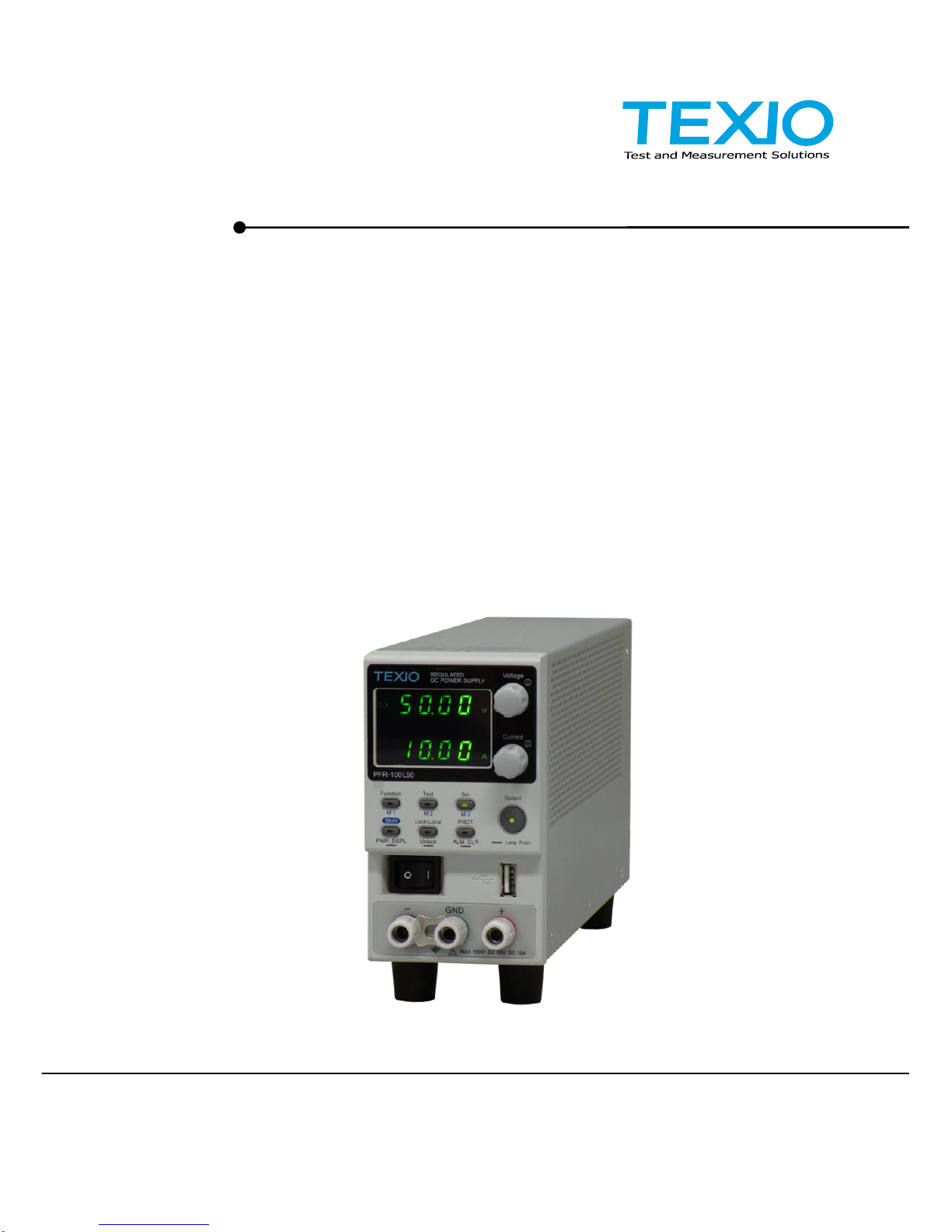
Front cover
PROGRAMMING MANUAL
B71-0481-01
WIDE RANGE DC POWER SUPPLY
PFR-100 SERIES
Page 2

■ About a trademark, a registered trademark
A company name and the brand name mentioned in this instruction
manual are the trademark or the registered trademark of each
company or group in each country and region.
■ About this instruction manual
When copying the part or all of contents of this instruction manual,
seek the copyright holder.
In addition, the specifications of the product and the contents of this
instruction manual are subject to change without notice for
improvement. Please check to our website for the latest version.
■ About firmware version
This programming manual is required firmware version 1.00 or higher.
Page 3

CONTENTS
Front cover ................................................................... 1
1. Configuration Settings .............................................. 1
1-1. Setting Configuration Settings ........................................ 1
2. Communication Interface .......................................... 5
2-1. USB Interface ................................................................ 5
2-1-1. USB Remote Interface .................................................................... 5
2-1-2. USB-CDC Remote Control Function Check .................................... 6
2-2. GPIB Interface ............................................................... 6
2-2-1. GPIB Remote Interface ................................................................... 6
2-2-2. GPIB Function Check ...................................................................... 7
2-3. LAN Interface................................................................. 9
2-3-1. Web Server Configuration ............................................................. 10
2-3-2. Web Server Remote Control Function Check................................ 11
2-3-3. Socket Server Configuration.......................................................... 12
2-3-4. Socket Server Function Check ...................................................... 12
2-4. Serial Interface ............................................................ 16
2-4-1. UART Remote Interface ................................ ................................ 16
2-4-2. UART Function Check ................................................................ ... 17
2-5. Multidrop Interface ....................................................... 18
2-5-1. Multiple Unit Connection ............................................................... 18
2-5-1-1. Multi-Drop mode .................................................................... 18
2-5-1-2. Multi-Drop mode Function Check .......................................... 20
3. Command Syntax .................................................... 22
4. Command List ......................................................... 24
4-1. Abort Command ........................................................... 24
4-1-1. :ABORt ................................ ................................ .......................... 24
4-2. Apply Commands ......................................................... 24
4-2-1. :APPLy .......................................................................................... 24
4-3. Display Commands ...................................................... 25
4-3-1. :DISPlay:MENU[:NAME] ............................................................... 25
4-3-2. :DISPlay[:WINDow]:TEXT:CLEar .................................................. 25
4-3-3. :DISPlay[:WINDow]:TEXT[:DATA] ................................................. 25
4-3-4. :DISPlay:BLINk .............................................................................. 26
4-4. Initiate Commands ....................................................... 26
4-4-1. :INITiate:CONTinuous[:TRANsient] ............................................... 26
4-4-2. :INITiate[:IMMediate]:NAME .......................................................... 26
4-4-3. :INITiate[:IMMediate][:TRANsient] ................................................. 27
4-5. Instrument Commands ................................................. 27
4-5-1. :INSTrument:SCAN ....................................................................... 27
4-5-2. :INSTrument:SELect ..................................................................... 27
4-5-3. :INSTrument:STATe ...................................................................... 27
4-5-4. :INSTrument:DISPlay .................................................................... 28
4-6. Measure Commands .................................................... 28
4-6-1. :MEASure[:SCALar]:ALL[:DC] ....................................................... 28
Page 4

4-6-2. :MEASure[:SCALar]:CURRent[:DC] .............................................. 28
4-6-3. :MEASure[:SCALar]:VOLTage[:DC] .............................................. 29
4-6-4. :MEASure[:SCALar]:POWer[:DC] .................................................. 29
4-7. Output Commands ................................ ....................... 29
4-7-1. :OUTPut:DELay:ON ...................................................................... 29
4-7-2. :OUTPut:DELay:OFF .................................................................... 29
4-7-3. :OUTPut:MODE ............................................................................. 30
4-7-4. :OUTPut[:STATe][:IMMediate] ....................................................... 30
4-7-5. :OUTPut[:STATe]:TRIGgered ........................................................ 31
4-7-6. :OUTPut:PROTection:CLEar ......................................................... 31
4-7-7. :OUTPut:PROTection:TRIPped ..................................................... 31
4-8. Sense Commands ........................................................ 31
4-8-1. :SENSe:AVERage:COUNt ............................................................ 31
4-9. Status Commands ........................................................ 32
4-9-1. :STATus:OPERation[:EVENt] ........................................................ 32
4-9-2. :STATus:OPERation:CONDition ................................................... 32
4-9-3. :STATus:OPERation:ENABle ........................................................ 32
4-9-4. :STATus:OPERation:PTRansition ................................................. 33
4-9-5. :STATus:OPERation:NTRansition ................................................. 33
4-9-6. :STATus:QUEStionable[:EVENt] ................................................... 33
4-9-7. :STATus:QUEStionable:CONDition ............................................... 34
4-9-8. :STATus:QUEStionable:ENABle ................................................... 34
4-9-9. :STATus:QUEStionable:PTRansition ............................................ 34
4-9-10. :STATus:QUEStionable:NTRansition .......................................... 34
4-9-11. :STATus:QUEStionable:INSTrument : ISUMmary<n>[:EVENt] .............. 35
4-9-12. :STATus:QUEStionable:INSTrument :ISUMmary<n>:CONDition ........... 35
4-9-13. :STATus:QUEStionable:INSTrument :ISUMmary<n>:ENABle ............... 35
4-9-14. :STATus:PRESet ......................................................................... 36
4-10. Source Commands ..................................................... 36
4-10-1.
[:SOURce]:CURRent[:LEVel][:IMMediate] [:AMPLitude]
...................... 36
4-10-2.
[:SOURce]:CURRent[:LEVel]:TRIGgered [:AMPLitude]
....................... 37
4-10-3. [:SOURce]:CURRent:LIMit:AUTO ............................................... 37
4-10-4. [:SOURce]:CURRent:PROTection:DELay ................................... 38
4-10-5. [:SOURce]:CURRent:PROTection[:LEVel] .................................. 38
4-10-6. [:SOURce]:CURRent:PROTection:TRIPped ............................... 39
4-10-7. [:SOURce]:CURRent:SLEWrate:RISing ...................................... 39
4-10-8. [:SOURce]:CURRent:SLEWrate:FALLing ................................... 39
4-10-9.
[:SOURce]:MODE?
......................................................................... 40
4-10-10.
[:SOURce]:VOLTage[:LEVel][:IMMediate] [:AMPLitude]
.................... 40
4-10-11.
[:SOURce]:VOLTage[:LEVel]:TRIGgered[:AMPLitude]
...................... 41
4-10-12. [:SOURce]:VOLTage:LIMit:AUTO ............................................. 41
4-10-13. [:SOURce]:VOLTage:LIMit:LOW ............................................... 42
4-10-14. [:SOURce]:VOLTage:PROTection[:LEVel] ................................ 42
4-10-15. [:SOURce]:VOLTage:PROTection :TRIPped ............................ 42
4-10-16. [:SOURce]:VOLTage:SLEWrate:RISing ................................ .... 43
4-10-17. [:SOURce]:VOLTage:SLEWrate:FALLing ................................. 43
4-11. System Function Command ........................................ 44
Page 5

4-11-1. :SYSTem:BEEPer[:IMMediate] .................................................... 44
4-11-2. :SYSTem:CONFigure:BEEPer[:STATe] ...................................... 44
4-11-3. :SYSTem:CONFigure:BLEeder[:STATe] ..................................... 45
4-11-4. :SYSTem:CONFigure:CURRent:CONTrol................................... 45
4-11-5. :SYSTem:CONFigure:VOLTage:CONTrol................................... 46
4-11-6. :SYSTem:CONFigure:OUTPut:PON [:STATe] ............................ 46
4-11-7.
:SYSTem:CONFigure:OUTPut:EXTernal:MODE
................................ 47
4-12. Communication system configuration Commands ........ 47
4-12-1. :SYSTem:COMMunicate:ENABle ................................................ 47
4-12-2. :SYSTem:COMMunicate:GPIB[:SELF]:ADDRess ....................... 48
4-12-3. :SYSTem:COMMunicate:LAN:IPADdress ................................... 48
4-12-4. :SYSTem:COMMunicate:LAN:GATEway ................................ .... 48
4-12-5. :SYSTem:COMMunicate:LAN:SMASk ........................................ 49
4-12-6. :SYSTem:COMMunicate:LAN:MAC ............................................ 49
4-12-7. :SYSTem:COMMunicate:LAN:DHCP .......................................... 49
4-12-8. :SYSTem:COMMunicate:LAN:DNS ............................................. 50
4-12-9. :SYSTem:COMMunicate:RLSTate .............................................. 50
4-12-10. :SYSTem:COMMunicate:TCPip:CONTrol ................................. 50
4-12-11. :SYSTem:COMMunicate:SERial [:RECeive]:TRANsmit:BAUD ............. 51
4-12-12. :SYSTem:COMMunicate:SERial [:RECeive]:TRANsmit:BITS .............. 51
4-12-13. :SYSTem:COMMunicate:SERial [:RECeive]:TRANsmit:PARity ........... 51
4-12-14. :SYSTem:COMMunicate:SERial [:RECeive]:TRANsmit:SBITs ............ 52
4-12-15. :SYSTem:COMMunicate:MULTidrop :CONTrol ........................ 52
4-12-16. :SYSTem:COMMunicate:USB:FRONt :STATe .......................... 52
4-12-17. :SYSTem:COMMunicate:USB:REAR :STATe ........................... 52
4-13. System Settings Commands ....................................... 53
4-13-1. :SYSTem:ERRor ......................................................................... 53
4-13-2. :SYSTem:KLOCk ........................................................................ 53
4-13-3. :SYSTem:KEYLock:MODE.......................................................... 53
4-13-4. :SYSTem:ERRor:ENABle ............................................................ 54
4-13-5. :SYSTem:PRESet ....................................................................... 54
4-13-6. :SYSTem:VERSion ..................................................................... 54
4-13-7. :SYSTem:REBoot ........................................................................ 54
4-14. Trigger Commands ..................................................... 54
4-14-1. :TRIGger:OUTPut:SOURce......................................................... 54
4-14-2. :TRIGger:OUTPut[:IMMediate] .................................................... 55
4-14-3. :TRIGger[:TRANsient]:SOURce .................................................. 55
4-14-4. :TRIGger[:TRANsient][:IMMediate] .............................................. 55
4-14-5. Trigger Commands Examples ..................................................... 56
4-15. IEEE 488.2 Common Commands ................................ 56
4-15-1. *CLS ............................................................................................ 56
4-15-2. *ESE ............................................................................................ 57
4-15-3. *ESR ........................................................................................... 57
4-15-4. *IDN ............................................................................................. 57
4-15-5. *OPC ........................................................................................... 58
4-15-6. *RCL ............................................................................................ 58
4-15-7. *RST ............................................................................................ 58
Page 6

4-15-8. *SAV ............................................................................................ 58
4-15-9. *SRE ........................................................................................... 59
4-15-10. *STB .......................................................................................... 59
4-15-11. *TRG ......................................................................................... 59
4-15-12. *TST .......................................................................................... 59
4-15-13. *WAI .......................................................................................... 60
5. Status Register Overview ........................................ 61
5-1. Introduction to the Status Registers .............................. 61
5-2. Configuration status register ........................................ 62
5-3. Questionable Status Register Group ............................. 63
5-4. Operation Status Register Group .................................. 66
5-5. Standard Event Status Register Group ......................... 67
5-6. Status Byte Register & Service Request Enable Register ...... 68
5-7. Error list ...................................................................... 69
5-7-1. Command Errors ........................................................................... 69
5-7-2. Execution Errors ............................................................................ 71
5-7-3. Device Specific Errors ................................................................... 73
5-7-4. Query Errors .................................................................................. 73
6. Appendix ................................................................. 75
6-1. Default Settings ........................................................... 75
6-2. Error Messages and other Messages ............................ 76
6-3. LED ASCII Table Character Set.................................... 77
Page 7
1
1. Configuration Settings
1-1. Setting Configuration Settings
Background
The normal configuration settings (F-01~F-61, F-71~F-78,
F-88, F-89) are used to configure or view system settings. Use
the following operation steps when configuring the interface
settings used in the Communication Interface chapter. (page 5)
Ensure the load is not connected.
Ensure the output is off.
Note
Configuration settings F-90~F-94 cannot be edited in the
Normal Function Settings. See the user manual for details.
F-20, F-21, F-25, F-30~F-35, F-78, F-89 settings can only be
viewed, not set.
Steps
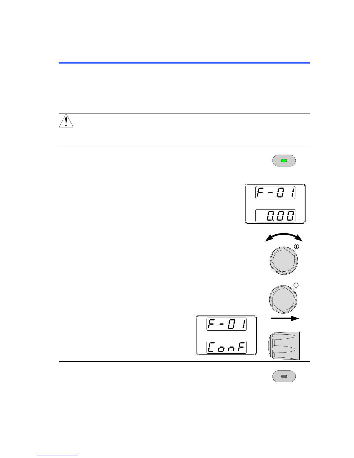
1.
Press the Function key. The function key will
light up.
Function
M1
2.
The display will show F-01 on the top and
the configuration setting for F-01 on the
bottom.
3.
Rotate the Voltage knob to change the F
setting.
Voltage
Range
F-00~F-61, F-71~F-78,
F-88~F-94
4.
Use the Current knob to set the parameter for
the chosen F setting.
Current
5.
Press the Voltage knob to
save the configuration
setting.
ConF will be displayed
when successful.
Voltage
Exit
Press the Function key again to exit the
configuration settings.
The Function key light will turn off.
Function
M1
Page 8

2
Configuration Table
Please use the configuration settings listed below when applying the configuration
settings.
Normal Function
Settings
Setting
Setting Range
Output ON delay time
F-01
0.00s~99.99s
Output OFF delay time
F-02
0.00s~99.99s
V-I mode slew rate select
F-03
0 = CV high speed priority
1 = CC high speed priority
2 = CV slew rate priority
3 = CC slew rate priority
Rising voltage slew rate
F-04
0.1V~100.0V/s (PFR-100L50)
0.1V~500.0V/s (PFR-100M250)
Falling voltage slew rate
F-05
0.1V~100.0V/s (PFR-100L50)
0.1V~500.0V/s (PFR-100M250)
Rising current slew rate
F-06
0.01A/s~20.00A/s (PFR-100L50)
0.001A/s~4.000A/s (PFR-100M250)
Falling current slew rate
F-07
0.01A/s~20.00A/s (PFR-100L50)
0.001A/s~4.000A/s (PFR-100M250)
Bleeder circuit control
F-09
0 = OFF, 1 = ON, 2 = AUTO
Buzzer ON/OFF control
F-10
0 = OFF, 1 = ON
Detection Time of OCP
F-12
0.0~2.0 sec
Current Setting Limit
(I-Limit)
F-13
0 = OFF (The limit function of current setting
is disabled.)
1 = ON (The limit function of current setting
is enabled.)
Voltage Setting Limit
(V-Limit)
F-14
0 = OFF (The limit function of voltage
setting is disabled.)
1 = ON (The limit function of voltage setting
is enabled.)
Memory Recall Display
F-15
0 = OFF, 1 = ON
Measurement Average
Setting
F-17
0 = Low, 1 = Middle, 2 = High
Lock Mode
F-19
0 = Lock Panel, Allow Output OFF
1 = Lock Panel, Allow Output ON/OFF
USB/GP-IB Settings
Front panel USB status*
F-20
0 = None, 1 = Mass Storage
Rear panel USB status*
F-21
0 = None, 2 = Linking PC
GP-IB Address
F-23
0~30
Show GPIB available
status*
F-25
0 = No GPIB, 1 = GPIB is available
Interface Select
F-29
0 = Disable, 1 = RS232, 2 = R485,
3 = USB-CDC / NO Mass Storage,
4 = GPIB, 5 = LAN SOCKET,
6 = LAN WEB
Page 9

3
LAN Settings
MAC Address-1*
F-30
0x00~0xFF
MAC Address-2*
F-31
0x00~0xFF
MAC Address-3*
F-32
0x00~0xFF
MAC Address-4*
F-33
0x00~0xFF
MAC Address-5*
F-34
0x00~0xFF
MAC Address-6*
F-35
0x00~0xFF
DHCP
F-37
0 = OFF, 1 = ON
IP Address-1
F-39
0~255
IP Address-2
F-40
0~255
IP Address-3
F-41
0~255
IP Address-4
F-42
0~255
Subnet Mask-1
F-43
0~255
Subnet Mask-2
F-44
0~255
Subnet Mask-3
F-45
0~255
Subnet Mask-4
F-46
0~255
Gateway-1
F-47
0~255
Gateway -2
F-48
0~255
Gateway -3
F-49
0~255
Gateway -4
F-50
0~255
DNS Address-1
F-51
0~255
DNS Address -2
F-52
0~255
DNS Address -3
F-53
0~255
DNS Address -4
F-54
0~255
Web Password
Enable/Disable
F-60
0 = Disable, 1 = Enable
Web Enter Password
F-61
0000~9999
UART Settings
UART Baud Rate
F-71
0 = 1200, 1 = 2400, 2 = 4800, 3 = 9600,
4 = 19200, 5 = 38400, 6 = 57600,
7 = 115200
UART Data Bits
F-72
0 = 7 bits, 1 = 8 bits
UART Parity
F-73
0 = None, 1 = Odd, 2 = Even
UART Stop Bit
F-74
0 = 1 bit, 1 = 2 bits
UART TCP
F-75
0 = SCPI, 1 = Reserve
UART Address
F-76
00~30
UART Multi-Drop control
F-77
0 = Disable, 1 = Master, 2 = Slave,
3 = Display Information
UART Multi-Drop status*
F-78
Displayed parameter: AA-S
AA: 0~30 (Address)
S: 0 = Off-line, 1 = On-line
System settings
Factory Default
Configuration
F-88
0 = None,
1 = Return to factory default settings
Page 10
4
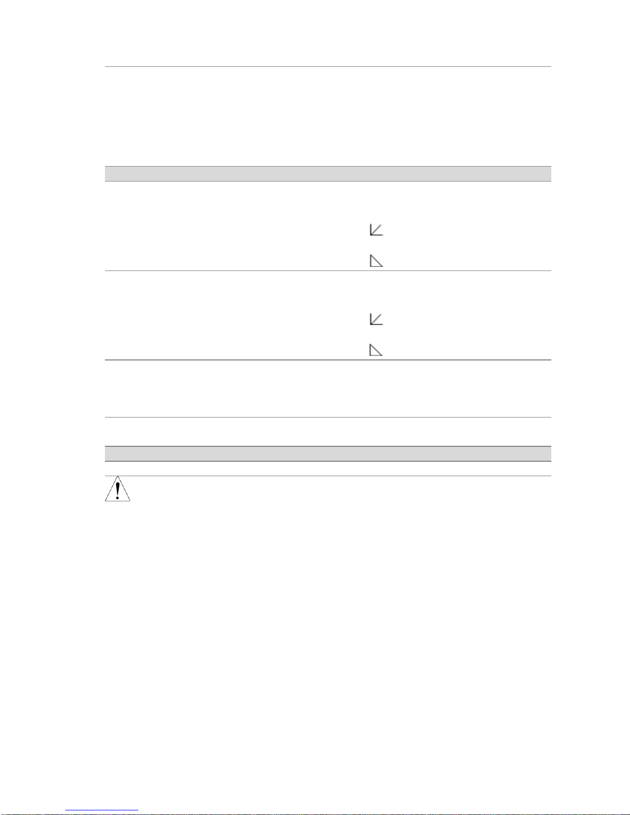
Show Version
F-89
0, 1 = Version
2, 3, 4, 5 = Build date (YYYYMMDD)
6, 7 = Keyboard CPLD Version
8, 9 = Analog-Control CPLD Version
A, B = Reserved
C, D, E, F = Kernel Build Date
(YYYYMMDD)
Power On Configuration Settings**
CV Control
F-90
0 = Panel control (local)
1 = External Voltage control
2 = External Resistance control-Rising
(Ext-R 10kΩ = Vo, max)
3 = External Resistance control-Falling
(Ext-R 10kΩ = 0)
CC Control
F-91
0 = Panel control (local)
1 = External Voltage control
2 = External Resistance control-Rising
(Ext-R 10kΩ = Io,max)
3 = External Resistance control-Falling
(Ext-R 10kΩ = 0)
Power ON Output
F-92
0 = Safe Mode (Output OFF at startup)
1 = Force Mode (Output ON at startup)
2 = Auto Mode (Status before last time
Power OFF)
External Output Logic
Control***
F-94
0 = High ON, 1 = Low ON,
2 = Disable
Special Function setting
Special Function
F-00
0000~9999
Note
*
These settings can only be viewed, not set.
**
Normally there are for display only. When setting, hold down
the Function key and power on.
***
This function is set by External Output ON / OFF Control
Page 11
5
2. Communication Interface
This chapter describes basic configuration of IEEE488.2 based remote control.
2-1. USB Interface
2-1-1. USB Remote Interface
Note
When using the USB Remote Interface, The USB port on the
front panel will become disabled and fail to be used.
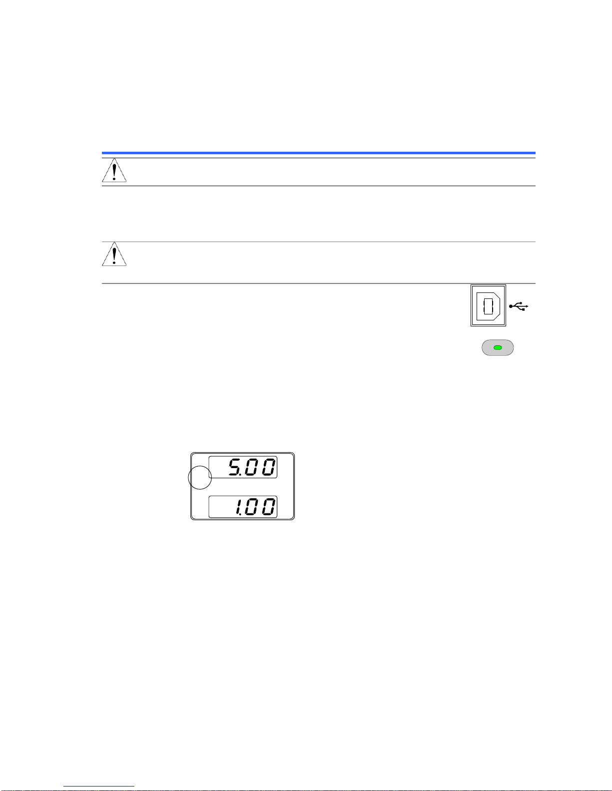
USB
Configuration
PC side connector
Type A, host
PFR-100 side connector
Rear panel Type B, slave
Speed
1.1 (full speed)
USB Device Class
USB-CDC
Note
Before using the USB remote control, you will need to install the
USB device driver (inf file) that is included on the CD
accompanying accessories.
Steps
1. Connect the USB cable to the rear panel USB B
port.
2. Press the Function key to enter the Normal
configuration settings and select F-29 (Interface
port). F-29 = 3 (USB-CDC).
Function
M1
3. Check to see that the USB is detected by PFR-100. The F-21
setting indicates the rear USB port.
F-21 = 0
Indicates the rear USB port is not detected.
F-21 = 1
Indicates the rear USB port is available.
4. The RMT indicator will turn on when a remote connection has
been established.
V
A
RMT
5. When the PC correctly recognizes "PFR", the USB driver is
installed and registered as a COM port. Open the device
manager and check the port.
If it is not recognized correctly, installation of the USB driver
is necessary.
Since this unit is displayed on "other device", right click on
the device and update the driver. Please copy the
downloaded USB driver from the attached CD or our HP to
the appropriate folder and specify the search destination.
Page 12

6
2-1-2. USB-CDC Remote Control Function Check
Please note that the port settings may not be confirmed if the
device driver is not used for this unit.
Please prepare the Terminal application (such as PuTTY or
RealTerm). Serial communication settings are as follows.
Baud rate
: 9600 bps
Data bits
: 8 bits Parity bit
: None
Stop bits
: 1 bit Flow control
: None
Run this query command via the terminal after the instrument
has been configured for USB remote control.
*IDN?
This should return the Manufacturer, Model name, Serial
number, and Firmware version in the following format.
TEXIO,PFR-100L50,TW1234567,01.01.12345678
Manufacturer : TEXIO
Model name : PFR-100L50
Serial number : TW1234567
Firmware version : 01.01.12345678
Termination character of commands and queries use the
^j (LF: Line Feed).
2-2. GPIB Interface
2-2-1. GPIB Remote Interface
To use GPIB, you must select a model with a GPIB. This is a factory installed
option and cannot be installed the end-user. Only one GPIB address can be
used at a time.
Configure GPIB
1. Ensure the PFR-100 is off before proceeding.
2. Connect the GPIB cable (part number: GTL-258) from a
GPIB controller to the GPIB port on the PFR-100.
3. Turn the PFR-100 on.
4. Press the Function key to enter the Normal
configuration settings.
Function
M1
5. Set the following GPIB settings.
F-29 = 4
Enable the GPIB port
F-23 = 0~30
Set the GPIB address (0~30/ Default : 8)
6. Check to see the GPIB option is detected by the PFR-100.
The F-25 setting indicates the GPIB port status.
F-25 = 0
Indicates that the GPIB port is not detected.
F-25 = 1
Indicates that the GPIB port is available.
Page 13

7
7. The RMT indicator will turn on when a remote connection has
been established.
V
A
RMT
GPIB constraints
Maximum 15 devices altogether, 20m cable length, 2m
between each device.
Unique address assigned to each device.
At least 2/3 of the devices turned On.
No loop or parallel connection.
2-2-2. GPIB Function Check
Background
To test the GPIB functionality, National Instruments
Measurement and Automation Explorer can be used. This
program is available on the NI website, www.ni.com., via a
search for the VISA Run-time Engine page, or “downloads” at
the following URL, http://www.ni.com/visa/
Requirements
PC Operating System(OS): Windows 7 or later
Functionality
check
1. Start the NI Measurement and Automation Explorer
(NI-MAX) program. Using Windows, press:
Start ->All Programs ->National Instruments ->Measurement
& Automation
Display and operated by a version of NI-MAX is different.
Please operate in accordance with the version you are using.
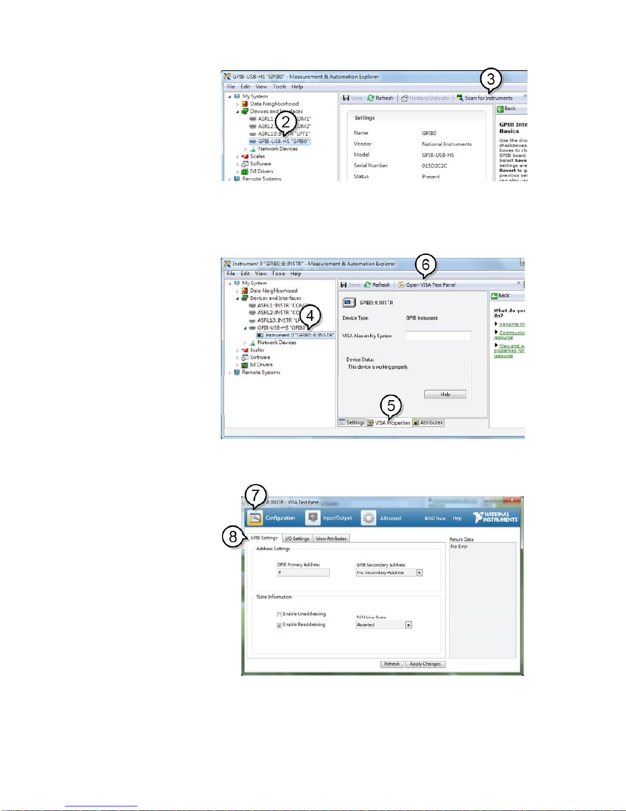
2. From the Configuration panel access;
My system>Devices and Interface>GPIB
3. Press Scan for Instruments.
Page 14
8
4. Select the device (GPIB address of PFR-100) that now
appears in the System>Devices and Interfaces >
GPIB-USB-HS “GPIBX” node.
5. Click on the VISA Properties tab on the bottom.
6. Click Open Visa Test Panel.
7. Click on Configuration.
8. Click on the GPIB Settings tab and confirm that the GPIB
settings are correct.
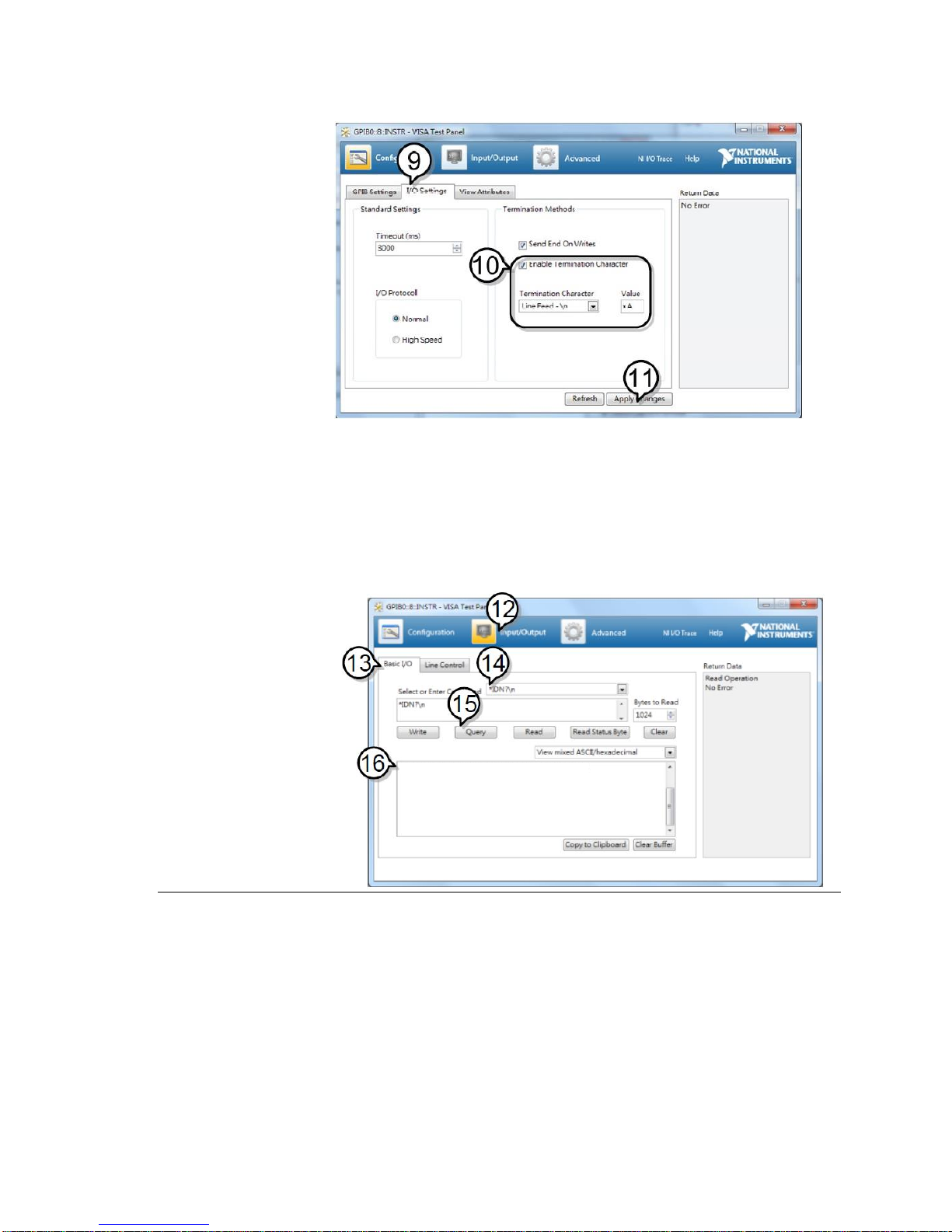
9. Click on the I/O Settings tab.
10. Make sure the Enable Termination Character check box is
checked, and the terminal character is \n (Value: xA).
Page 15
9
11. Click Apply Changes.
12. Click on Input/Output.
13. Click on the Basic/IO tab.
14. Enter *IDN? in the Select or Enter Command drop down box.
15. Click Query.
16. The *IDN? query will return the Manufacturer, model name,
serial number and firmware version in the dialog box.
TEXIO,PFR-100L50,TW1234567,01.01.12345678
TEXIO,PFR-100L50,TW1234567,01.01.12345678\n
2-3. LAN Interface
The Ethernet interface can be configured for a number of different applications.
Ethernet can be configured for basic remote control or monitoring using a web
server or it can be configured as a socket server.
The PFR-100 series supports both DHCP connections so the instrument can be
automatically connected to an existing network or alternatively, network settings
can be manually configured.
Page 16
10
Ethernet
configuration
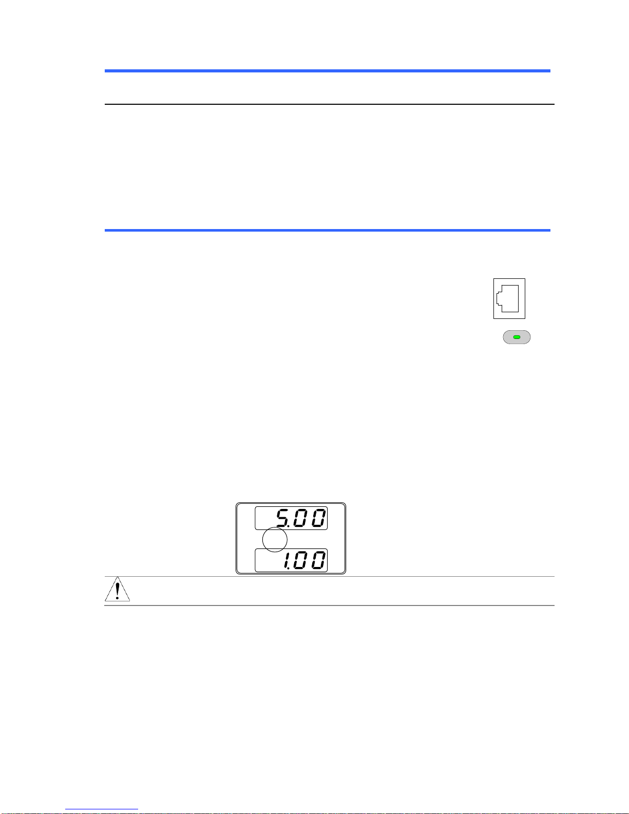
For details on how to configure the Ethernet settings
Parameters
DHCP Enable/Disable
MAC Address (display only)
Subnet Mask
IP Address
DNS Address
Gateway
Web Password Enable/Disable
Web Enter Password
0000~9999(Default 0000)
Socket port:
2268(Fixed)
2-3-1. Web Server Configuration
Configuration
This configuration example will configure the PFR-100 as a
web server and use DHCP to automatically assign an IP
address to the PFR-100.
1. Connect an Ethernet cable from the network to
the rear panel Ethernet port.
LAN
2. Press the Function key to enter the Normal
configuration settings.
Function
M1
Set the following LAN settings:
F-29 = 6
Interface port select & Turn LAN (Web)
on
F-37 = 1
Enable DHCP
F-60 = 0 or 1
Set to 0 to disable web password, set to
1 to enable web password.
F-61 =
0000~9999
Set the web password
3. The LAN indicator will turn on when a network cable is
plugged in.
LAN
V
A
CV
Note
It may be necessary to cycle the power or refresh the web
browser to connect to a network.
Page 17
11
2-3-2. Web Server Remote Control Function Check
Functionality
check
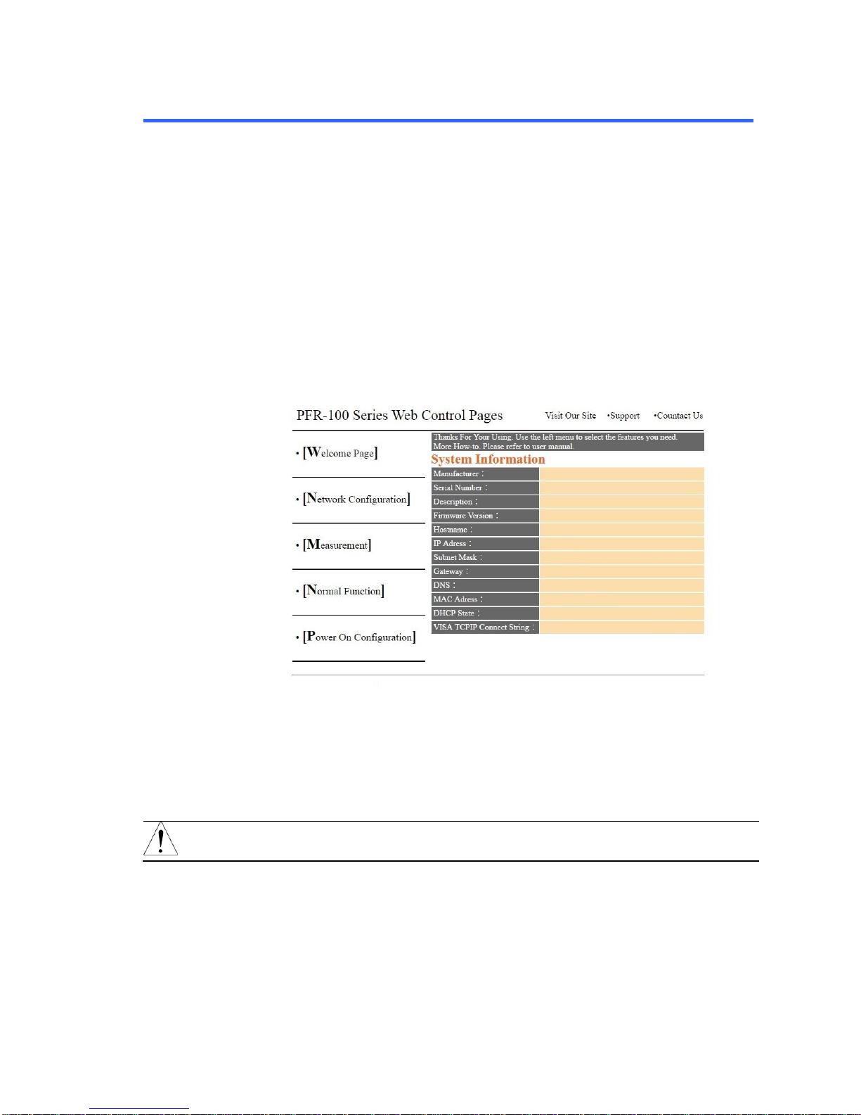
Enter the IP address of the power supply in a web browser
after the instrument has been configured as a web server.
The web server allows you to monitor the function settings of
the PFR-100.
You can check the IP address by checking F-39 to F-42.
F-39 = AAA
IP Address part 1 of 4
F-40 = BBB
IP Address part 2 of 4
F-41 = CCC
IP Address part 3 of 4
F-42 = DDD
IP Address part 4 of 4
http://AAA.BBB.CCC.DDD
The web browser interface appears.
TEXIO
TEXIO,PFR-100L50
192.168.0.103
255.255.255.0
192.168.0.1
0.0.0.0
ON
TCPIP0::192.168.0.103::2268::SOCKET
Copyright 2017 ⓒ TEXIO TECHNOLOGY CORPORATION All Rights Reserved.
TW1234567
01.01.12345678
P-1234567
00-11-22-AA-BB-02
The web browser interface allows you to access the following:
Network configuration settings
Measurement setting
Normal Function setting
Power On Configuration setting
Note
If the network connection can not be confirmed, update the
power switch again or update the web browser loading.
Page 18

12
2-3-3. Socket Server Configuration
Configuration
This configuration example will configure the PFR-100 socket
server.
The following configuration settings will manually assign the
PFR-100 an IP address and enable the socket server. The
socket server port number is fixed at 2268.
4. Connect an Ethernet cable from the network to
the rear panel Ethernet port.
LAN
5. Press the Function key to enter the Normal
configuration settings.
Function
M1
Set the following LAN settings (setting examples from F-39 to
F-54):
F-29 = 5
Turn LAN (Socket) on
F-37 = 0
Disable DHCP
F-39 = 192
IP Address part 1 of 4
F-40 = 168
IP Address part 2 of 4
F-41 = 5
IP Address part 3 of 4
F-42 = 133
IP Address part 4 of 4
F-43 = 255
Subnet Mask part 1 of 4
F-44 = 255
Subnet Mask part 2 of 4
F-45 = 255
Subnet Mask part 3 of 4
F-46 = 0
Subnet Mask part 4 of 4
F-47 = 192
Gateway part 1 of 4
F-48 = 168
Gateway part 2 of 4
F-49 = 5
Gateway part 3 of 4
F-50 = 101
Gateway part 4 of 4
F-51 = 192
DNS part 1 of 4
F-52 = 168
DNS part 2 of 4
F-53 = 5
DNS part 3 of 4
F-54 = 101
DNS part 4 of 4
2-3-4. Socket Server Function Check
Background
To test the socket server functionality, National Instruments
Measurement and Automation Explorer can be used. This
program is available on the NI website, www.ni.com., via a
search for the VISA Run-time Engine page, or “downloads” at
the following URL, http://www.ni.com/visa/
Requirements
PC Operating System(OS): Windows 7 or higher
Functionality
check
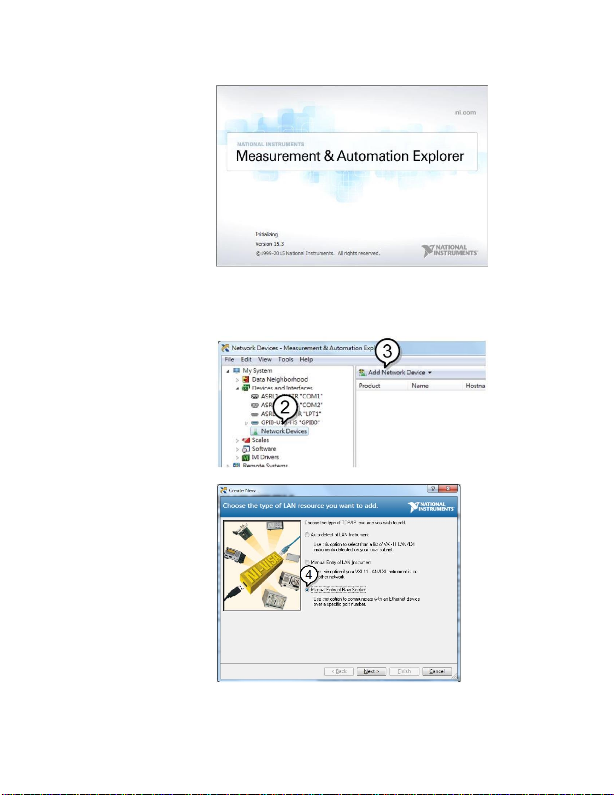
1. Start the NI Measurement and Automation Explorer (MAX)
program.
start>All PROGRAM>National Instruments>Measurement &
Automation
Page 19
13
Display and operated by a version of NI-MAX is different.
Please operate in accordance with the version you are using.
2. From the Configuration panel access
My System>Devices and Interfaces>Network Devices
3. Press Add New Network Device>Visa TCP/IP Resource...
4. Select Manual Entry of Raw Socket from the popup window.
5. Enter the IP address and the port number of the PFR-100.
The port number is fixed at 2268.
6. Click the Validate button.
Page 20
14
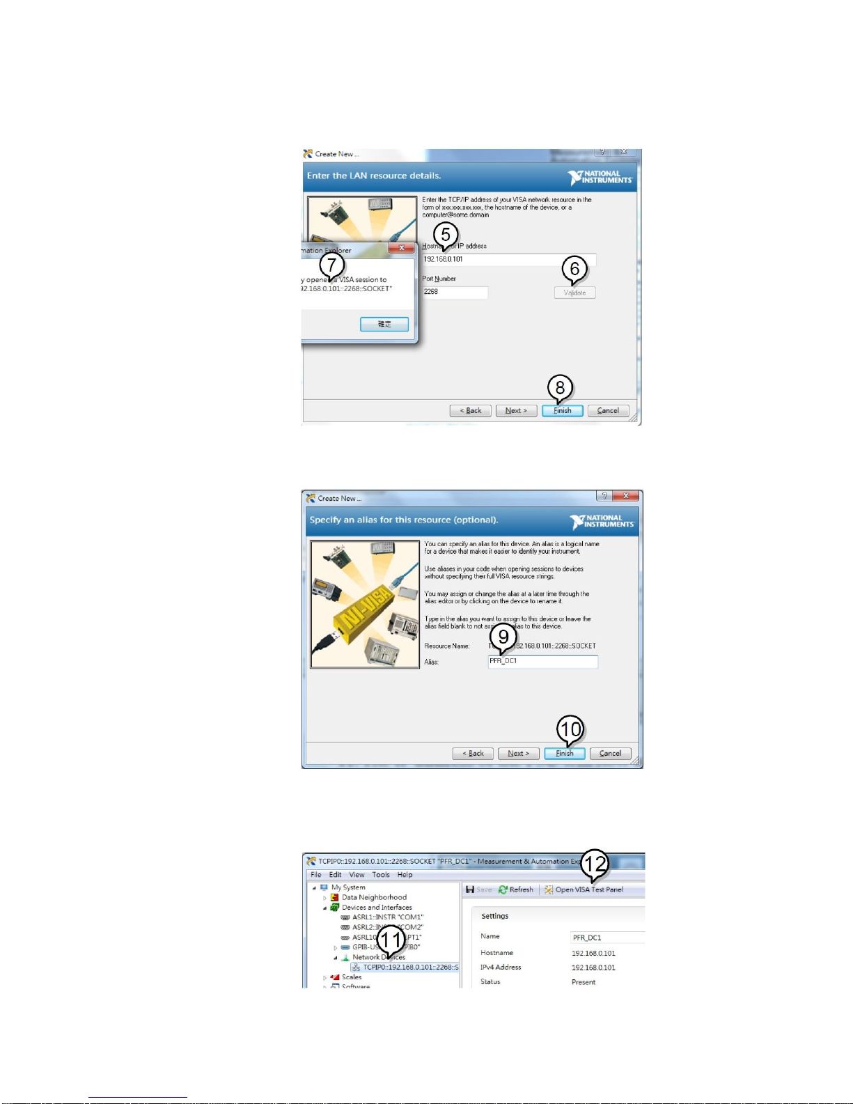
7. A popup will appear if a connection is successfully
established.
8. Click Next.
9. Next configure the Alias (name) of the PFR-100 connection.
Example:PFR-100_DC1
10. Click finish.
11. The IP address of the PFR-100 will now appear under
Network Devices in the configuration panel. Select this icon
now.
12. Press Open VISA Test Panel.
13. Click the Configuration icon.
Page 21
15
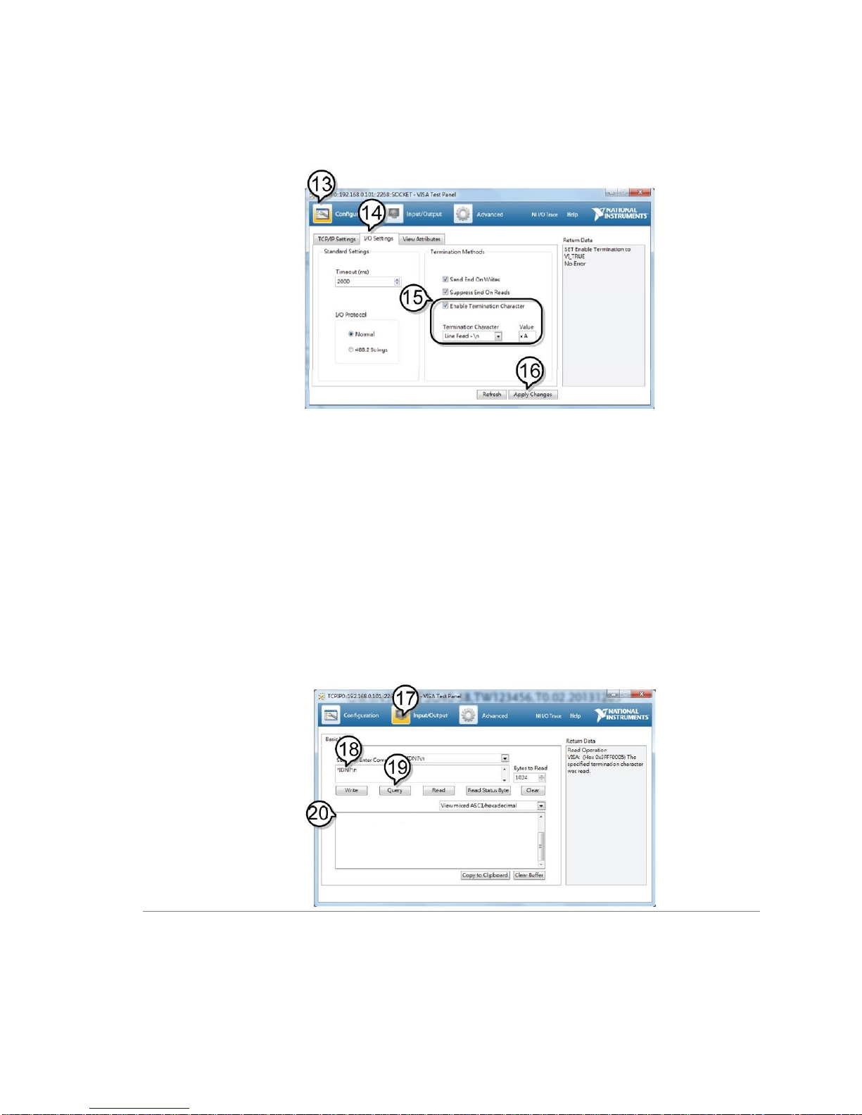
14. Click on I/O Settings.
15. Make sure the Enable Termination Character check box is
checked, and the terminal character is \n (Value: xA).
16. Click Apply Changes.
17. Click the Input/Output icon.
18. Enter *IDN? in the Select or Enter Command dialog box if it
is not already.
19. Click the Query button.
20. The *IDN? query will return the Manufacturer, model name,
serial number and firmware version in the dialog box.
TEXIO,PFR-100L50,TW1234567,01.01.12345678
Manufacturer: TEXIO
Model name : PFR-100L50
Serial number : TW1234567
Firmware version : 01.01.12345678
TEXIO,PFR-100L50,TW1234567,01.01.12345678
Page 22
16
2-4. Serial Interface
2-4-1. UART Remote Interface
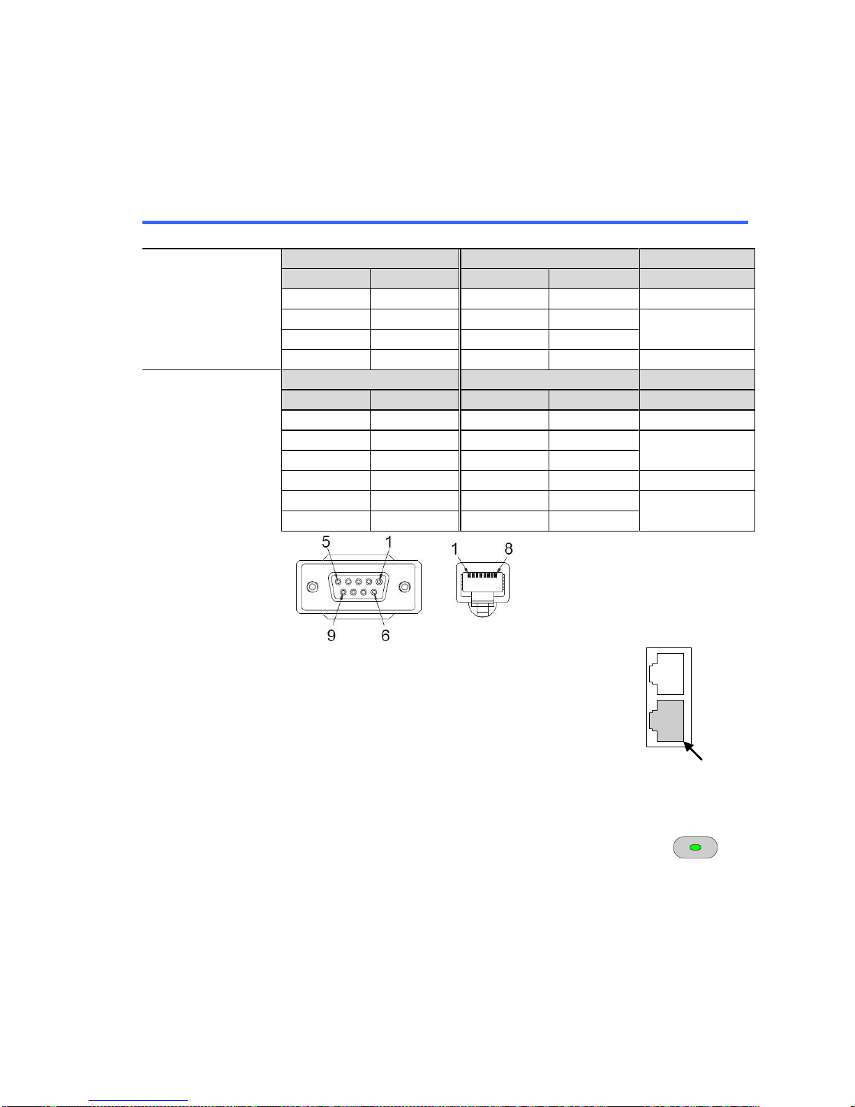
The PFR-100 uses the IN & OUT ports for UART communication coupled with
RS232 (Part number: GTL-259) or RS485 adapters (Part number: GTL-260).
When using only one unit with RS485, connect the end terminal connector to
Remote-OUT. The end terminal connector is not required in RS232.
The pin outs for the adapters are shown below.
RS232 cable
with DB9 &
RJ-45 shielded
connectors
GTL-259
DB-9 Connector
Remote-IN Port
Remarks
Pin No.
Name
Pin No.
Name
Housing
Shield
Housing
Shield
2 RX 7 TX
Twisted pair
3
TX 8 RX
5
SG 1 SG
RS485 cable
with DB9 &
RJ-45 shielded
connectors
GTL-260
DB-9 Connector
Remote-IN Port
Remarks
Pin No.
Name
Pin No.
Pin No.
Name
Housing
Shield
Housing
Shield
9 TXD-
6
RXD-
Twisted pair
8
TXD+
3
RXD+
1
SG 1 SG
5 RXD-
5
TXD-
Twisted pair
4
RXD+
4
TXD+
Steps
1. Connect the RS232 serial cable
(GTL-259) or RS485 serial cable
(GTL-260) to the Remote-IN port on the
real panel.
Connect the other end of the cable to the
PC.
When using only one unit with RS485,
connect the end terminal connector to
Remote-OUT.
OUT
IN
RS232
/RS485
1
2. Press the Function key to enter the Normal
configuration settings.
Set the following UART settings:
Function
M1
F-29 = 1 or 2
Interface port:
1 = RS232 or 2 = RS485
F-71 = 0~7
Set the baud rate:
0 = 1200, 1 = 2400, 2 = 4800,
3 = 9600, 4 = 19200, 5 = 38400,
6 = 57600, 7 = 115200
F-72 = 0 or 1
Data bits: 0 = 7 or 1 = 8
Page 23
17
F-73 = 0~2
Parity 0 = none, 1 = odd, 2 = even
F-74 = 0 or 1
Stop bits:
0 = 1, 1 = 2
F-75 = 0
TCP: 0 = SCPI
F-76 = 0~30
UART address for multi-unit remote
connection.
F-77 = 0~3
Multi-Drop control:
0 = Disable, 1 = Master, 2 = Slave,
3 = Display Information
F-78 = 0~30
Multi-Drop status display
Displayed parameter: AA-S
AA: 0~30 (Address),
S: 0~1 (Off-line/On-line status).
3. The RMT indicator will turn on when a remote connection
has been established.
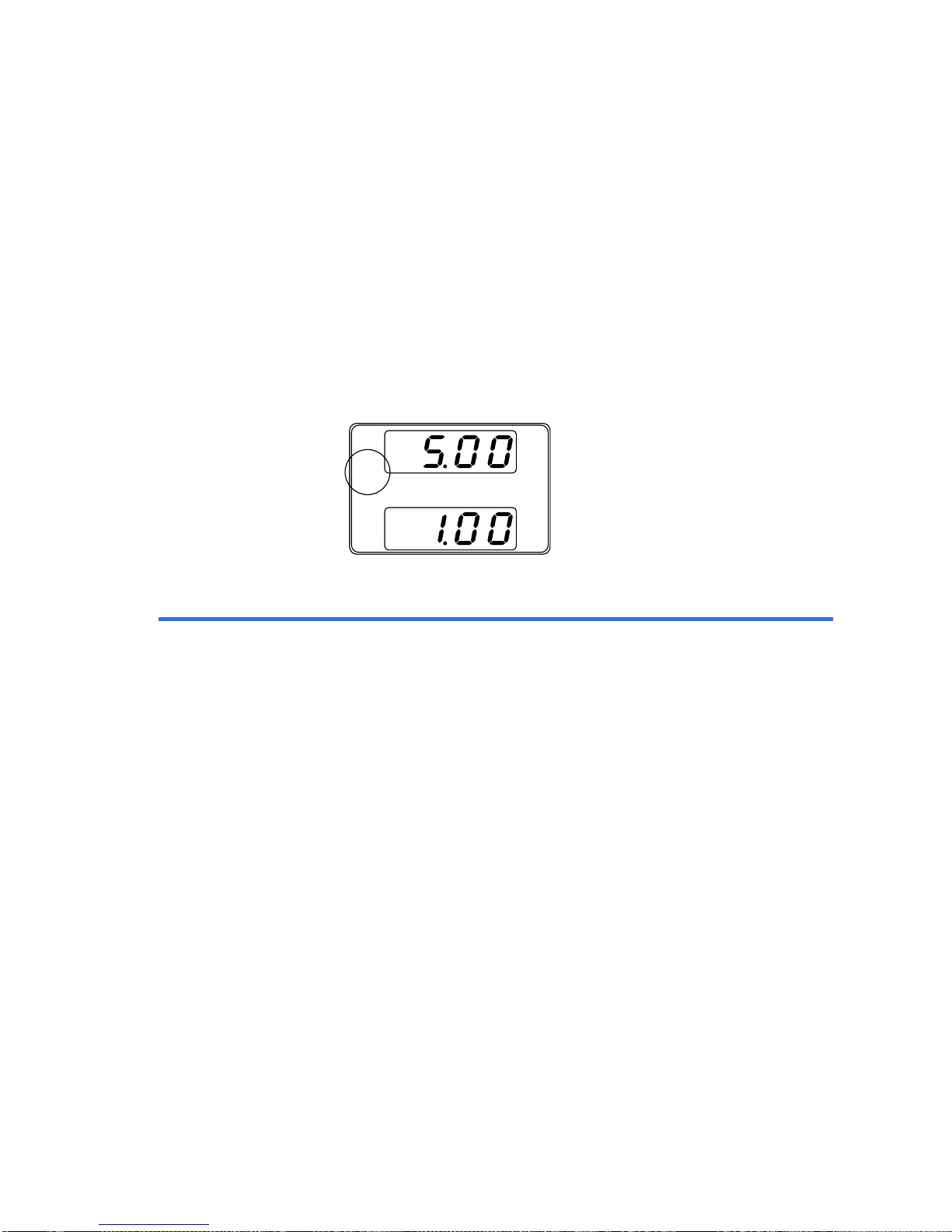
V
A
RMT
2-4-2. UART Function Check
Functionality
check
Invoke a terminal application such as Realterm.
To check the COM port No, see the Device Manager in the
PC.
Run this query command via the terminal application after
the instrument has been configured for either RS232 or
RS485 remote control.
*IDN?
This should return the Manufacturer, Model number, Serial
number, and Firmware version in the following format:
TEXIO,PFR-100L50,TW1234567,01.01.12345678
Manufacturer: TEXIO
Model name : PFR-100L50
Serial number : TW1234567
Firmware version : 01.01.12345678
^j (LF:Line Feed) can be used as the terminal character
when entering the queries/commands from a terminal
application.
Page 24
18
2-5. Multidrop Interface
2-5-1. Multiple Unit Connection
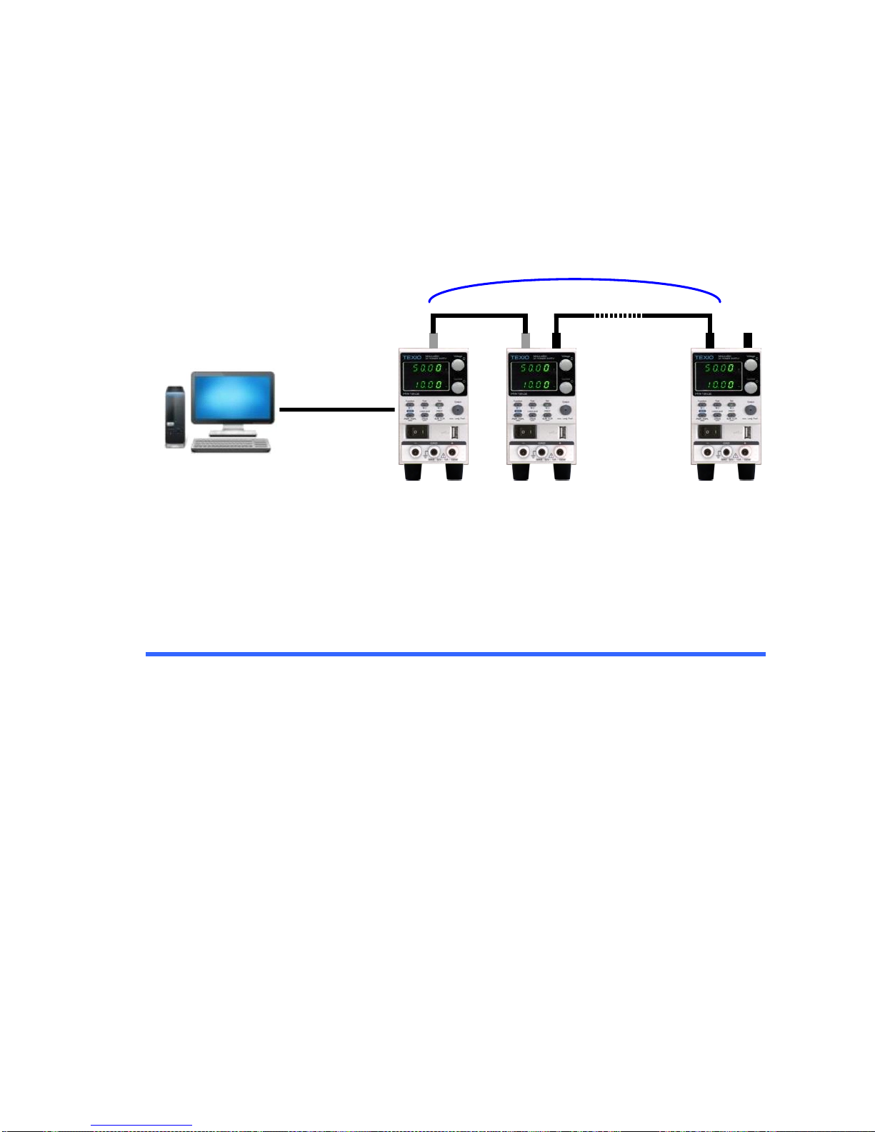
The PFR-100 power supplies can have up to 31 units daisy-chained together
using the 8 pin connectors (Remote-IN OUT ports) on the rear panel. The first
unit (master) in the chain is remotely connected to a PC using USB, GPIB or
LAN (Multi-Drop mode). Each subsequent unit (slave) is daisy-chained to the
next using a RS485 local bus. The Remote-OUT port on the last terminal must
be terminated by the end terminal connector.
USB/LAN/GP-IB
RS-485
MAX 31 Set
RS-485
Termi
nator
There is a mode for controlling multiple units. This mode allows the user to enter
the SCPI commands developed for the instrument (Multi-Drop mode). In this
mode, only the Multi-Drop parameters have to be specified. Each unit is
assigned a unique address and can then be individually controlled from the host
PC.
2-5-1-1. Multi-Drop mode
Operation
1. All units must be powered down before starting the
Multi-Drop mode configuration.
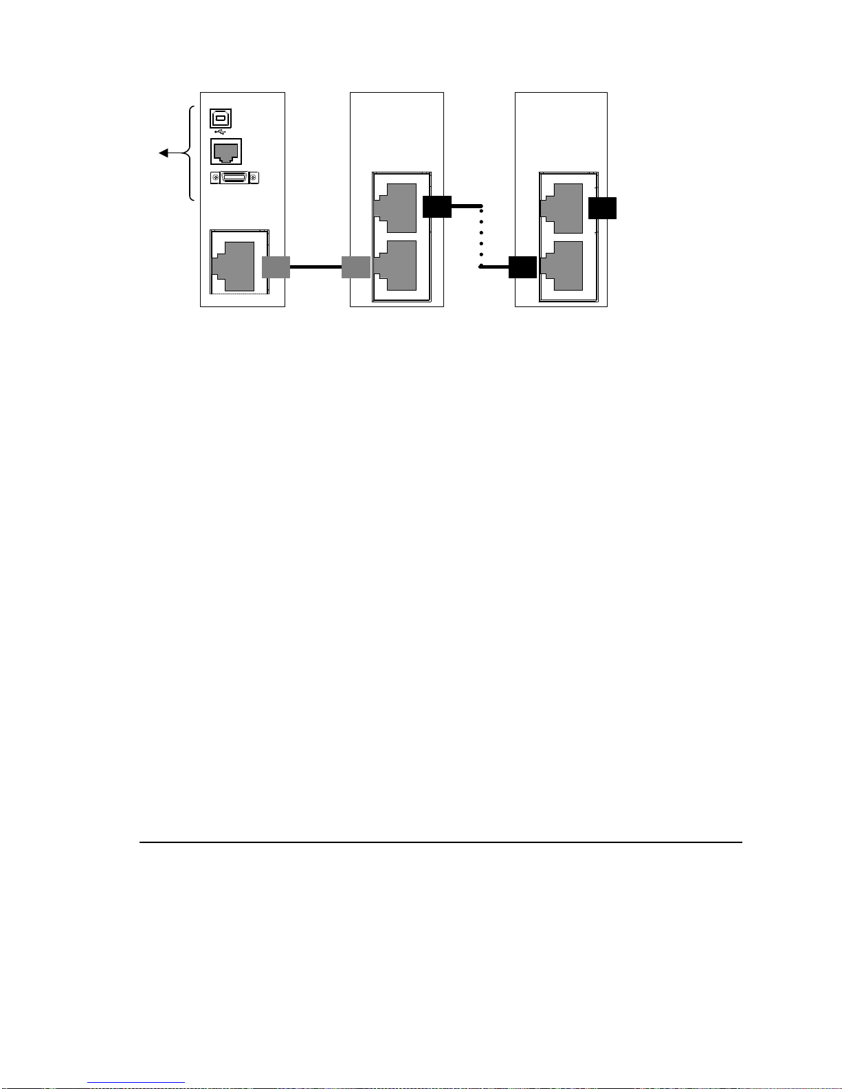
2. Connect the first unit’s LAN, USB or GPIB port to a PC.
3. Connect the Remote-OUT port on the first unit to the IN
port of the second unit using the master serial link cable
(gray plug)GTL-261.
4. Connect all the remaining units between the Remote-OUT
port and the IN port with the slave serial link cable (black
plug) GTL-262 until all the desired units have been
daisy-chained together.
5. Terminate the Remote-OUT port of the last unit with the
end terminal connector included in the GTL-261.
Page 25
19
Unit #2
PC
USB
LAN
GPIB
Master
OUT
IN
OUT
OUT
IN
Unit #N
Master
Cable
Slave
Cable
Terminator
6. Power up all slave units.
7. Set the addresses of all slave units using the F-76
parameter.
F-76 = 00~30
Set the address of the master unit. It
must be a unique address identifier.
8. Set the Multi-Drop setting parameter (F-77) to Slave for all
slave units.
F-77 = 2
Set the Multi-Drop setting to slave.
9. Power up the master unit.
10. Set the addresses of the master units using the F-76
parameter.
F-76 = 00~30
Set the address of the unit. It must be a
unique address identifier.
11. You can check the slaves' addresses by using the F-77
parameter on the master unit.
F-77 = 3
Display on each slave units the
configured address. This can show if
identical addresses have been assigned
individually to each slave units.
12. Set the Multi-Drop setting parameter (F-77) to Master.
F-77 = 1
Set the Multi-Drop setting to master.
13. You can display the status of each slave unit by using the
F-78 parameter.
F-78 = 00~30
Displayed parameter: AA-S
AA: 0~30 (Address),
S: 0~1 (Off-line/On-line status).
14. Multiple units can now be operated using SCPI commands.
Page 26
20
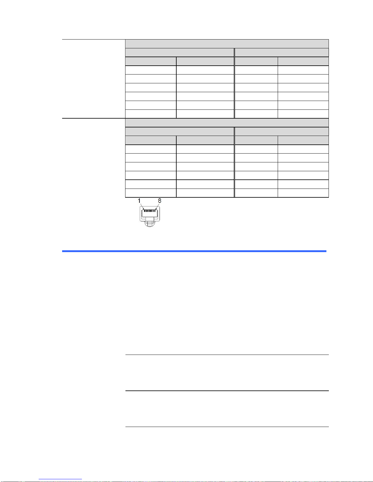
Slave serial link
cable with RJ-45
shielded
connector (black
plug)
GTL-262
RS-485 slave serial link pin assignment
8 Pin Connector (IN)
8 Pin Connector (OUT)
Pin No.
Name
Pin No.
Name
Housing
Shield
Housing
Shield
1
SG
1
SG
6
TXD-
6
TXD-
3
TXD+
3
TXD+
5
RXD-
5
RXD-
4
RXD+
4
RXD+
Master serial link
cable with RJ-45
shielded
connector (gray
plug)
GTL-261
RS-485 master serial link pin assignment
8 Pin Connector (IN)
8 Pin Connector (OUT)
Pin No.
Name
Pin No.
Name
Housing
Shield
Housing
Shield
1
SG
1
SG
6
TXD-
5
RXD-
3
TXD+
4
RXD+
5
RXD-
6
TXD-
4
RXD+
3
TXD+
2-5-1-2. Multi-Drop mode Function Check
Functionality
check
Invoke a terminal application such as Realterm.
To check the COM port No, see the Device Manager in the
PC.
When using the Multi-Drop mode, the entire SCPI
command list developed for the PFR-100 can be used.
Each unit can be individually controlled after a slave unit
has been selected. For this function check, we will assume
that the master unit is assigned to address 0, while a slave
is assigned address 5.
Run this query command via the terminal application after
the instruments have been configured for multi-unit control
with Multi-Drop mode. See page 18.
:INST:SEL 0
← Press ENTER after typing.
*IDN?
← Press ENTER after typing.
TEXIO,PFR-100L50,TW1234567,01.01.12345678
:INST:SEL 5
← Press ENTER after typing.
*IDN?
← Press ENTER after typing.
TEXIO,PFR-100L50,TW7654321,01.01.12345678
:INST:SEL 6
← Press ENTER after typing.
Page 27

21
Selects the unit with address 6 (not configured in our
example). An error is displayed on the master front panel.
:SYST:ERR?
← Press ENTER after typing.
Settings conflict
Query the system errors. “Settings conflict” is returned.
:INST:STAT?
← Press ENTER after typing.
33,0
Returns the active units and master unit in the bus.
33 = 0b100001
The units at address 0 and address 5 are on-line.
0
Master device's address is 0.
Page 28

22
3. Command Syntax
Compatible
Standard
IEEE488.2
Partial compatibility
SCPI 1999
Partial compatibility
Command
Structure
SCPI commands follow a tree-like structure, organized into
nodes. Each level of the command tree is a node. Each
keyword in a SCPI command represents each node in the
command tree. Each keyword (node) of a SCPI command is
separated by a colon (:).
For example, the diagram below shows an SCPI sub-structure
and a command example.
DC
MEASure
SCALar
POWer
VOLTage
CURRent
DC
DC
:MEASure:SCALar:CURRent:DC?
Command types
There are a number of different instrument commands and
queries. A command sends instructions or data to the unit and a
query receives data or status information from the unit.
Command types
Simple
A single command with/without a parameter
Example
*IDN?
Query
A query is a simple or compound command
followed by a question mark (?). A parameter (data)
is returned.
Example
:meas:curr:dc?
Compound
Two or more commands on the same command
line.
Compound commands are separated with either a
semi-colon (;) or a semi-colon and a colon (;:).
A semi-colon is used to join two related commands,
with the caveat that the last command must begin
at the last node of the first command.
A semi-colon and colon are used to combine two
commands from different nodes.
Example
:meas:volt:dc?;:meas:curr:dc?
Command
Forms
Commands and queries have two different forms, long and
short. The command syntax is written with the short form of the
command in capitals and the remainder (long form) in lower
case.
The commands can be written in capitals or lower-case, just so
long as the short or long forms are complete. An incomplete
command will not be recognized.
Below are examples of correctly written commands.
Page 29
23
Long form
:STATus:OPERation:NTRansition?
:STATUS:OPERATION:NTRANSITION?
:status:operation:ntransition?
Short form
:STAT:OPER:NTR?
:stat:oper:ntr?
Square Brackets
[]
Commands that contain square brackets indicate that the
contents are optional. The function of the command is the same
with or without the square bracketed items, as shown below.
Both ":DISPlay:MENU[:NAME]?" and ":DISPlay:MENU?" are
both valid forms.
Command
Format
1.5,5.2
1 2 3 4 5
APPLY
1. Command header
2. Space
3. Parameter 1
4. Comma (no space before/after
comma)
5. Parameter 2
Parameters
Type
Description
Example
<Boolean>
Boolean logic
0, 1
<NR1>
integers
0, 1, 2, 3
<NR2>
decimal numbers
0.1, 3.14, 8.5
<NR3>
floating point
4.5e-1, 8.25e+1
<NRf>
any of NR1, 2, 3
1, 1.5, 4.5e-1
<string>
Sets the eight characters of 20H ~ 7EH of
ASCII characters. Must be enclosed in
quotation marks (") string.
<block data>
Definitive length arbitrary block data. A single
decimal digit followed by data. The decimal
digit specifies how many 8-bit data bytes follow.
Message
Terminator
LF
Line feed code
Page 30
24
4. Command List
4-1. Abort Command
4-1-1. :ABORt
Set
Description
This command will cancel any triggered actions.
Syntax
:ABORt
Example
:ABOR
Cancel trigger action.
4-2. Apply Commands
4-2-1. :APPLy
Set
Query
Description
This command is used to set both the voltage and current. The
voltage and current will be output as soon as the function is
executed if the programmed values are within the accepted
range.
An execution error will occur if the programmed values are not
within accepted ranges.
The Apply command will set the voltage/current values but these
values will not be reflected on the display until the Output is On or
if the DISPlay:MENU:NAME 3 (set menu) command is used.
Syntax
:APPLy { <voltage> | MINimum | MAXimum}[,{<current> |
MINimum | MAXimum }]
Query Syntax
:APPLy?
Parameter
<voltage>
<NRf>(V) 0% ~ 105% of the rated output voltage.
<current>
<NRf>(A) 0% ~ 105% of the rated output current.
MINimum
0 volts/0 amps
MAXimum
Maximum value for the present range.
Return
parameter 1
<NR2>
Return value of the voltage.
Return
parameter 2
<NR2>
Return value of the current.
Example 1
:APPL 5.05,1.1
Sets to 1.1A current, to 5.05V voltage.
Example 2
:APPL 3.5
Sets to 3.5V voltage only.
Query
example
:APPL?
>+5.050, +1.100
Returns a value of setting current (1.1A) and voltage (5.05V) .
Page 31
25
4-3. Display Commands
4-3-1. :DISPlay:MENU[:NAME]
Set
Query
Description
This command selects a screen menu or queries the current
screen menu.
Syntax
:DISPlay:MENU[:NAME] <NR1>
Query Syntax
:DISPlay:MENU[:NAME]?
Parameter
0
Measurement-Voltage / Current
1 Measurement-Voltage / Power
2 Measurement-Power / Current
3 Set Menu(Voltage/Current)
4 OVP / OCP Menu
5~99
Not Used.
100~199
F-00~99 Menu.
Example
:DISP:MENU 0
Sets the display to the Voltage/Current display screen.
Query
example
:DISP:MENU?
>0
Return the code of the display state.
(0 = Measurement-Voltage / Current)
4-3-2. :DISPlay[:WINDow]:TEXT:CLEar
Set
Description
Clears the text on the main screen.
Syntax
:DISPlay[:WINDow]:TEXT:CLEar
Example
:DISP:TEXT:CLE
Clears the text on the main screen.
4-3-3. :DISPlay[:WINDow]:TEXT[:DATA]
Set
Query
Description
Sets or queries the data text that will be written to the display.
Writing to the display will overwrite data that is currently on the
screen. Overwriting a display area with a shorter string may or
may not overwrite the screen.
Syntax
:DISPlay[:WINDow]:TEXT[:DATA] “<string>”
Query Syntax
:DISPlay[:WINDow]:TEXT[:DATA]?
Parameter
“<string>”
Sets the eight characters of 20H ~ 7EH of ASCII
characters. Must be enclosed in quotation marks (")
string.
Return
parameter
“<string>”
Return a text string enclosed in quotation marks (").
Example
:DISP:TEXT “ABCD”
Sets the screen the text data of "ABCD".
Page 32
26
Query
example
:DISP:TEXT?
>“ABCD”
Return a string of text data displayed.
4-3-4. :DISPlay:BLINk
Set
Query
Description
Turns blink on or off for the display.
Syntax
:DISPlay:BLINk { <Boolean> | OFF | ON }
Query Syntax
:DISPlay:BLINk?
Parameter
0 | OFF
Turns blink OFF
1 | ON
Turns blink ON
Return
parameter
<Boolean>
Example
:DISP:BLIN 1
Turns blink ON.
Query
example
:DISP:BLIN?
>0
Return the status of the blink display.
4-4. Initiate Commands
4-4-1. :INITiate:CONTinuous[:TRANsient]
Set
Query
Description
This command continuously initiates software triggers for the
transient or output triggers.
Syntax
:INITiate:CONTinuous[:TRANsient] { <bool> | OFF | ON }
Query Syntax
:INITiate:CONTinuous[:TRANsient]?
Parameter
0 | OFF
OFF
1 | ON
ON
Return
parameter
0
OFF
1
ON
Example
:INIT:CONT 1
Turns on the continuous trigger.
Query
example
:INIT:CONT?
>1
It returns the code of the current state. The trigger is valid.
4-4-2. :INITiate[:IMMediate]:NAME
Set
Description
This command starts the TRANsient or OUTPut trigger.
Syntax
:INITiate[:IMMediate]:NAME {TRANsient|OUTPut}
Parameter
TRANsient
Starts the TRANsient trigger.
OUTPut
Starts the OUTPut trigger.
Example
:INIT:NAME TRAN
Starts the Transient trigger.
Page 33
27
4-4-3. :INITiate[:IMMediate][:TRANsient]
Set
Description
This command controls the enabling of output triggers. When a
trigger is enabled, a trigger causes the specified action to occur. If
the trigger system is not enabled, all triggers are ignored.
Syntax
:INITiate[:IMMediate][:TRANsient]
Example
:INIT
Generate a trigger.
4-5. Instrument Commands
4-5-1. :INSTrument:SCAN
Set
Description
Links the units which could be scanned from system when using
Multi-Drop mode.
Syntax
:INSTrument:SCAN
Example
:INST:SCAN
Scan the linked device.
4-5-2. :INSTrument:SELect
Set
Query
Description
Specifies the address of the unit to which communication will be
established when using the Multi-Drop mode.
Syntax
:INSTrument:SELect {<NR1>}
Query Syntax
:INSTrument:SELect?
Parameter
<NR1>
The address of the unit to be selected (0~30).
Return
parameter
<NR1>
The currently selected address.
Example
:INST:SEL 30
The currently selected address is 30.
Query
example
:INST:SEL?
>30
Returns the currently selected address. The address 30 is
selected.
4-5-3. :INSTrument:STATe
Query
Description
Displays the status (on-line/off-line) of each slave unit and the
address of master unit, when using the Multi-Drop mode.
Query Syntax
:INSTrument:STATe?
Return
parameter 1
<NR1>
0~2147483647 (2147483647=2^31-1)
Each bit of the binary value corresponds to a unit from
0 to 30 (LSB to MSB). The bit will be set to 1 when the
corresponding unit is on-line.
Page 34
28
Return
parameter 2
<NR1>
0~30
This value represents the master address.
Query
example
:INST:STAT?
>+33, 0
33 = 0b100001
The units at address 0 and address 5 are on-line.
Master device's address is 0.
4-5-4. :INSTrument:DISPlay
Set
Description
Display your own address information (F-76) on all slave units
when using the Multi-Drop mode. This command is the same as
the “F-77 = 3” of the Master unit.
Syntax
:INSTrument:DISPlay
Example
:INST:DISP
Displays the address information on the slave unit.
4-6. Measure Commands
4-6-1. :MEASure[:SCALar]:ALL[:DC]
Query
Description
Takes a measurement and returns the average output current
and voltage.
Query Syntax
:MEASure[:SCALar]:ALL[:DC]?
Return
parameter 1
<NR2>
Returns the voltage (V).
Return
parameter 2
<NR2>
Returns the current (A)
Query
example
:MEAS:ALL?
>+1.000, +2.000
Returns the average output voltage (V) and current (A),
respectively. The output of 1.000 V/2.000 A.
4-6-2. :MEASure[:SCALar]:CURRent[:DC]
Query
Description
Takes a measurement and returns the average output current.
Query Syntax
:MEASure[:SCALar]:CURRent[:DC]?
Return
parameter
<NR2>
Returns the current in amps. The unit is (A).
Query
example
:MEAS:CURR?
>+1.000
Returns the average output current (A). The output is 1.000 A.
Page 35
29
4-6-3. :MEASure[:SCALar]:VOLTage[:DC]
Query
Description
Takes a measurement and returns the average output voltage.
Query Syntax
:MEASure[:SCALar]:VOLTage[:DC]?
Return
parameter
<NR2>
Returns the voltage in volts. The unit is (V).
Query
example
:MEAS:VOLT?
>+5.000
Returns the average output voltage (V). The output is 5.000 V.
4-6-4. :MEASure[:SCALar]:POWer[:DC]
Query
Description
Takes a measurement and returns the average output power.
Query Syntax
:MEASure[:SCALar]:POWer[:DC]?
Return
parameter
<NR2>
Returns the power in watts. The unit is (W).
Query
example
:MEAS:POW?
>+10.000
Returns the average output wattage (W). The output is 10.000 W.
4-7. Output Commands
4-7-1. :OUTPut:DELay:ON
Set
Query
Description
Sets the Delay Time in seconds for turning the output on (F-01).
The delay is set to 0.00 by default.
Syntax
:OUTPut:DELay:ON <NRf>
Query Syntax
:OUTPut:DELay:ON?
Parameter
<NRf>
0.00~99.99 seconds, where 0 = no delay.
Return
parameter
<NR2>
Returns the delay on time in seconds until the output is
turned on.
Example
:OUTP:DEL:ON 1
Sets 1 second to the Delay Time for turning the output on.
Query
example
:OUTP:DEL:ON?
>+10.000
Returns the delay on time in seconds until the output is turned on.
4-7-2. :OUTPut:DELay:OFF
Set
Query
Description
Sets the Delay Time in seconds for turning the output off (F-02).
The delay is set to 0.00 by default.
Syntax
:OUTPut:DELay:OFF <NRf>
Query Syntax
:OUTPut:DELay:OFF?
Parameter
<NRf>
0.00~99.99 seconds, where 0 = no delay.
Page 36
30
Return
parameter
<NR2>
Returns the delay on time in seconds until the output is
turned off.
Example
:OUTP:DEL:OFF 1
Sets 1 second to the Delay Time for turning the output off.
Query example
:OUTP:DEL:OFF?
>+10.000
Returns the delay on time in seconds until the output is turned off.
4-7-3. :OUTPut:MODE
Set
Query
Description
Sets the PFR-100 output mode. This is the equivalent to the F-03
(V-I Mode Slew Rate Select) settings.
Syntax
:OUTPut:MODE {<NR1> | CVHS | CCHS | CVLS | CCLS}
Query Syntax
:OUTPut:MODE?
Parameter
0 / CVHS
CV high speed priority
1 / CCHS
CC high speed priority
2 / CVLS
CV slew rate priority
3 / CCLS
CCV slew rate priority
Return
parameter
<NR1>
Returns the output mode.
Example
:OUTP:MODE CVHS
Sets the output mode.
Query
example
:OUTP:MODE?
>0
Returns the output mode.
4-7-4. :OUTPut[:STATe][:IMMediate]
Set
Query
Description
Turns the output on or off.
Syntax
:OUTPut[:STATe][:IMMediate] {<Boolean> | OFF | ON}
Query Syntax
:OUTPut[:STATe][:IMMediate]?
Parameter
0 / OFF
Turns the output off.
1 / ON
Turns the output on.
Return
parameter
<Boolean>
Returns output status of the instrument.
Example
:OUTP ON
Sets output status of the instrument.
Query
example
:OUTP?
>1
Returns output status of the instrument.
Page 37
31
4-7-5. :OUTPut[:STATe]:TRIGgered
Set
Query
Description
Turns the output on or off when a software trigger is generated.
Syntax
:OUTPut[:STATe]:TRIGgered {<Boolean> | OFF | ON}
Query Syntax
:OUTPut[:STATe]:TRIGgered?
Parameter
0 / OFF
Turns the output off when a software trigger is
generated (*TRG).
1 / ON
Turns the output on when a software trigger is
generated.
Return
parameter
<Boolean>
Returns output trigger status of the instrument
(*TRG).
Example
:OUTP:TRIG ON
Sets output trigger status of the instrument.
Query
example
:OUTP:TRIG?
>1
Returns output trigger status of the instrument.
4-7-6. :OUTPut:PROTection:CLEar
Set
Description
Clears over-voltage, over-current and over-temperature (OVP,
OCP, OHP) protection circuits.
It also clears the shutdown protection circuit. The AC failure
protection cannot be cleared.
Syntax
:OUTPut:PROTection:CLEar
Example
:OUTP:PROT:CLE
Clears the protection circuit
4-7-7. :OUTPut:PROTection:TRIPped
Query
Description
Returns the state of the protection circuits (OVP, OCP, OHP).
Query Syntax
:OUTPut:PROTection:TRIPped?
Return
parameter
<Boolean>
0 = Protection circuits are not tripped.
1 = Protection circuits are tripped
Query
example
:OUTP:PROT:TRIP?
>0
Return the state of protection circuit.
4-8. Sense Commands
4-8-1. :SENSe:AVERage:COUNt
Set
Query
Description
Determines the level of smoothing for the average setting. This is
the equivalent to the F-17 function setting. (F-17)
Syntax
:SENSe:AVERage:COUNt {<NR1> | LOW | MIDDle | HIGH}
Page 38
32
Query Syntax
:SENSe:AVERage:COUNt?
Parameter
0 / LOW
Low level of smoothing.
1 / MIDDle
Middle level of smoothing.
2 / HIGH
High level of smoothing.
Return
parameter
<NR1>
Returns the level of smoothing.
Example
:SENS:AVER:COUN 1
Sets the level of smoothing to middle.
Query
example
:SENS:AVER:COUN?
>0
Return the state of smoothing for the average setting.
4-9. Status Commands
4-9-1. :STATus:OPERation[:EVENt]
Query
Description
Queries the Operation Status Event register and clears the
contents of the register.
Query Syntax
:STATus:OPERation[:EVENt]?
Return
parameter
<NR1>
Returns the bit sum of the Operation Status Event
register.
Query
example
:STAT:OPER?
>0
Return the value of the Operation Status Event register.
4-9-2. :STATus:OPERation:CONDition
Query
Description
Queries the Operation Condition register. This query will not clear
the register.
Query Syntax
:STATus:OPERation:CONDition?
Return
parameter
<NR1>
Returns the bit sum of the Operation Condition register.
Query
example
:STAT:OPER:COND?
>0
Return the value of the Operation Condition register.
4-9-3. :STATus:OPERation:ENABle
Set
Query
Description
Sets or queries the bit sum of the Operation Status Enable
register.
Syntax
:STATus:OPERation:ENABle <NRf>
Query Syntax
:STATus:OPERation:ENABle?
Parameter
<NR1>
0~32767
Example
:STAT:OPER:ENAB 1
Sets the Operation Status Enable register.
Page 39
33
Query
example
:STAT:OPER:ENAB?
>1
Return the value of the Operation Status Enable register.
4-9-4. :STATus:OPERation:PTRansition
Set
Query
Description
Sets or queries the bit sum of the positive transition filter of the
Operation Status register.
Syntax
:STATus:OPERation:PTRansition <NRf>
Query Syntax
:STATus:OPERation:PTRansition?
Parameter
<NR1>
0~32767
Example
:STAT:OPER:PTR 1
Sets the positive transition filter of the Operation Status register.
Query
example
:STAT:OPER:PTR?
>1
Return the value of the positive transition filter of the Operation
Status register.
4-9-5. :STATus:OPERation:NTRansition
Set
Query
Description
Sets or queries the bit sum of the negative transition filter of the
Operation Status register.
Syntax
:STATus:OPERation:NTRansition <NRf>
Query Syntax
:STATus:OPERation:NTRansition?
Parameter
<NR1>
0~32767
Example
:STAT:OPER:NTR 1
Sets the negative transition filter of the Operation Status register.
Query
example
:STAT:OPER:NTR?
>1
Return the value of the negative transition filter of the Operation
Status register.
4-9-6. :STATus:QUEStionable[:EVENt]
Query
Description
Queries the bit sum of the Questionable Status Event register.
This query will also clear the contents of the register.
Query Syntax
:STATus:QUEStionable[:EVENt]?
Return
parameter
<NR1>
Returns the bit sum of the Questionable Status Event
register.
Query
example
:STAT:QUES?
>0
Return the value of the Questionable Status Event register.
Page 40
34
4-9-7. :STATus:QUEStionable:CONDition
Query
Description
Queries the Questionable Condition register. This query will not
clear the register.
Query Syntax
:STATus:QUEStionable:CONDition?
Return
parameter
<NR1>
Returns the bit sum of the Questionable Condition
register.
Query
example
:STAT:QUES:COND?
>0
Return the value of the Questionable Condition register.
4-9-8. :STATus:QUEStionable:ENABle
Set
Query
Description
Sets or queries the bit sum of the Questionable Status Enable
register.
Syntax
:STATus:QUEStionable:ENABle <NRf>
Query Syntax
:STATus:QUEStionable:ENABle?
Parameter
<NR1>
0~32767
Example
:STAT:QUES:ENAB 1
Sets the Questionable Status Enable register.
Query
example
:STAT:QUES:ENAB?
>1
Return the value of the Questionable Status Enable register.
4-9-9. :STATus:QUEStionable:PTRansition
Set
Query
Description
Sets or queries the bit sum of the positive transition filter of the
Questionable Status register.
Syntax
:STATus:QUEStionable:PTRansition <NRf>
Query Syntax
:STATus:QUEStionable:PTRansition?
Parameter
<NR1>
0~32767
Example
:STAT:QUES:PTR 1
Sets the positive transition filter of the Questionable Status
register.
Query
example
:STAT:QUES:PTR?
>1
Return the value of the positive transition filter of the
Questionable Status register.
4-9-10. :STATus:QUEStionable:NTRansition
Set
Query
Description
Sets or queries the bit sum of the negative transition filter of the
Questionable Status register.
Syntax
:STATus:QUEStionable:NTRansition <NRf>
Page 41
35
Query Syntax
:STATus:QUEStionable:NTRansition?
Parameter
<NR1>
0~32767
Example
:STAT:QUES:NTR 1
Sets the negative transition filter of the Questionable Status
register.
Query
example
:STAT:QUES:NTR?
>1
Return the value of the negative transition filter of the
Questionable Status register.
4-9-11. :STATus:QUEStionable:INSTrument
: ISUMmary<n>[:EVENt]
Query
Description
Queries the bit sum of the Questionable Instrument Summary
Status Event register. This query will also clear the contents of the
register (Multi-Drop mode).
Query Syntax
:STATus:QUEStionable:INSTrument:ISUMmary<n>[:EVENt]?
Parameter
<n>
1~3
Return
parameter
<NR1>
0~32767
Query
example
:STAT:QUES:INST:ISUM1?
>1
Queries the bit sum of the Questionable Instrument Summary
Status Event register.
4-9-12. :STATus:QUEStionable:INSTrument
:ISUMmary<n>:CONDition
Query
Description
Queries the status (bit sum) of the Questionable
Instrument Summary Status Condition register.
This query will not clear the register (Multi-Drop
mode).
Query Syntax
:STATus:QUEStionable:INSTrument:ISUMmary<n>:CONDition?
Parameter
<n>
1~3
Return
parameter
<NR1>
0~32767
Query
example
:STAT:QUES:INST:ISUM1:COND?
>1
Queries the bit sum of the Questionable Instrument Summary
Status Condition register.
4-9-13. :STATus:QUEStionable:INSTrument
:ISUMmary<n>:ENABle
Set
Query
Description
Sets or queries the bit sum of the Questionable Instrument
Summary Status Enable register. (Multi-Drop mode).
Syntax
:STATus:QUEStionable:INSTrument:ISUMmary<n>:ENABle
<NR1>
Page 42
36
Query Syntax
:STATus:QUEStionable:INSTrument:ISUMmary<n>:ENABle?
Parameter
<n>
1~3
<NR1>
0~32767
Return
parameter
<NR1>
0~32767
Example
:STAT:QUES:INST:ISUM1:ENAB 1
Sets the bit0 of the Questionable Instrument Summary Status
Enable register.
Query
example
:STAT:QUES:INST:ISUM1:ENAB?
>1
Bit0 is set.
4-9-14. :STATus:PRESet
Set
Description
This command resets the ENABle register, the PTRansistion filter
and NTRansistion filter on the Operation Status and Questionable
Status Registers. The registers/filters will be reset to a default
value.
Default Register/Filter Values
Setting
QUEStionable Status Enable
0x0000
QUEStionable Status Positive Transition
0x7FFF
QUEStionable Status Negative Transition
0x0000
QUEStionable Instrument Summary1 Status Enable
0x7FFF
QUEStionable Instrument Summary2 Status Enable
0x7FFF
QUEStionable Instrument Summary3 Status Enable
0x7FFF
Operation Status Enable
0x0000
Operation Status Positive Transition
0x7FFF
Operation Status Negative Transition
0x0000
Summary: The Questionable Status Enable registers and the
Operation Status Enable registers are both reset to 0.
The Questionable Status and Operation Status Positive
Transition filters are all set high (0x7FFF) and the Negative
Transition filters are all set low (0x0000).
I.e., only positive transitions will be recognized for the
Questionable Status and Operation Status registers.
Syntax
:STATus:PRESet
Example
:STAT:PRES
Sets the initial value to Questionable status and Operation status.
4-10. Source Commands
4-10-1.
[:SOURce]:CURRent[:LEVel][:IMMediate]
[:AMPLitude]
Set
Query
Description
Sets or queries the current level in amps. For externally set
current levels (from the analog control connector) the set current
level is returned.
Page 43
37
Syntax
[:SOURce]:CURRent[:LEVel][:IMMediate][:AMPLitude]
{<NRf>|MINimum | MAXimum}
Query Syntax
[:SOURce]:CURRent[:LEVel][:IMMediate][:AMPLitude]?
[MINimum | MAXimum]
Parameter
<NRf>
0%~105% of the rated current output level.
MINimum
Minimum current level.
MAXimum
Maximum current level.
Return
parameter
<NR2>
Return the level of the output current.
Example
:CURR 5
Sets the output current level.
Query
example 1
:CURR?
>+5.120
Return the setting level of the output current.
Query
example 2
:CURR? MAX
>+10.500
Return the maximum setting level of the output current.
4-10-2.
[:SOURce]:CURRent[:LEVel]:TRIGgered
[:AMPLitude]
Set
Query
Description
Sets or queries the current level in amps when a software trigger
has been generated.
Syntax
[:SOURce]:CURRent[:LEVel]:TRIGgered[:AMPLitude]
{<NRf>|MINimum | MAXimum}
Query Syntax
[:SOURce]:CURRent[:LEVel]:TRIGgered[:AMPLitude]?
[MINimum | MAXimum]
Parameter
<NRf>
0%~105% of the rated current output in amps.
MINimum
Minimum current level.
MAXimum
Maximum current level.
Return
parameter
<NR2>
Return the level of the output current of software
trigger.
Example
:CURR:TRIG 10
Sets the output current level of software trigger.
Query
example 1
:CURR:TRIG?
>+10.000
Return the setting level of the output current of software trigger.
Query
example 2
:CURR:TRIG? MAX
>+10.500
Return the maximum setting level of the output current of
software trigger.
4-10-3. [:SOURce]:CURRent:LIMit:AUTO
Set
Query
Description
Enables or disables the limit on the current setting (F-13).
Syntax
[:SOURce]:CURRent:LIMit:AUTO {<Boolean> | OFF | ON}
Query Syntax
[:SOURce]:CURRent:LIMit:AUTO?
Page 44
38
Parameter
OFF | 0
Disable the setting current limit.
ON | 1
Enable the setting current limit.
Return
parameter
<Boolean>
Returns the setting in <boolean> format.
Example
:CURR:LIM:AUTO 0
Disables the current limit.
Query
example
:CURR:LIM:AUTO?
>0
Returns the limit state. Disables the current limit.
4-10-4. [:SOURce]:CURRent:PROTection:DELay
Set
Query
Description
Sets the Delay Time for OCP in seconds for turning the output off
(F-12). The delay is set to 0.0 by default.
Syntax
[:SOURce]:CURRent:PROTection:DELay {<NR2> | MINimum |
MAXimum}
Query Syntax
[:SOURce]:CURRent:PROTection:DELay?
Parameter
<NR2>
0.1~2.0 seconds, where 0 = no delay
MAXimum
The maximum allowed delay time (2.0).
MINimum
The minimum allowed delay time (0.1).
Return
parameter
<NR2>
Returns the delay time in seconds
Example
:CURR:PROT:DEL MAX
Sets the OCP delay to the maximum (2.0).
Query
example
:CURR:PROT:DEL?
>2.0
Returns the current setting value. Set to 2.0 seconds.
4-10-5. [:SOURce]:CURRent:PROTection[:LEVel]
Set
Query
Description
Sets or queries the OCP level in amps.
Syntax
[:SOURce]:CURRent:PROTection[:LEVel] {<NRf>|MINimum |
MAXimum}
Query Syntax
[:SOURce]:CURRent:PROTection[:LEVel]? [MINimum |
MAXimum]
Parameter
<NRf>
OCP level.
0%~110% of the rated current output in amps.
MINimum
Minimum OCP level.
MAXimum
Maximum OCP level.
Return
parameter
<NR2>
Returns the OCP level.
Example
:CURR:PROT 5
Sets the OCP level.
Query
example 1
:CURR:PROT?
>+5.000
Returns the OCP level.
Page 45
39
Query
example 2
:CURR:PROT? MIN
>+0.200
Returns the minimum OCP level.
4-10-6. [:SOURce]:CURRent:PROTection:TRIPped
Query
Description
Returns the state of the OCP.
Query Syntax
[:SOURce]:CURRent:PROTection:TRIPped?
Return
parameter
<Boolean>
0
The OCP has not been tripped.
1
The OCP has been tripped.
Query
example
:CURR:PROT:TRIP?
>0
The OCP has not been tripped.
4-10-7. [:SOURce]:CURRent:SLEWrate:RISing
Set
Query
Description
Sets or queries the rising current slew rate. This is only applicable
for CC slew rate priority mode.
Syntax
[:SOURce]:CURRent:SLEWrate:RISing {<NRf>|MINimum |
MAXimum}
Query Syntax
[:SOURce]:CURRent:SLEWrate:RISing? [MINimum | MAXimum]
Parameter
<NRf>
0.01A/s~20.00A/s (PFR-100L50)
0.001A/s~4.000A/s (PFR-100M250)
MINimum
Minimum rising current slew rate.
MAXimum
Maximum rising current slew rate.
Return
parameter
<NR2>
Returns the rising current slew rate in amps.
Example
:CURR:SLEW:RIS 20
Sets the rising current slew rate to 20A/ms.
Query
example 1
:CURR:SLEW:RIS?
>+5.000
Returns the rising current slew rate.
Query
example 2
:CURR:SLEW:RIS? MAX
>+20.000
Returns the maximum rising current slew rate.
4-10-8. [:SOURce]:CURRent:SLEWrate:FALLing
Set
Query
Description
Sets or queries the falling current slew rate. This is only
applicable for CC slew rate priority mode.
Syntax
[:SOURce]:CURRent:SLEWrate:FALLing {<NRf>|MINimum |
MAXimum}
Query Syntax
[:SOURce]:CURRent:SLEWrate:FALLing? [MINimum |
MAXimum]
Page 46
40
Parameter
NRf
0.01A/s~20.00A/s (PFR-100L50)
0.001A/s~4.000A/s (PFR-100M250)
MINimum
Minimum falling current slew rate.
MAXimum
Maximum falling current slew rate.
Return
parameter
<NR2>
Returns the falling current slew rate in amps.
Example
:CURR:SLEW:FALL 1
Sets the rising current slew rate to 1A/ms.
Query
example 1
:CURR:SLEW:FALL?
>+5.000
Returns the falling current slew rate.
Query
example 2
:CURR:SLEW:FALL? MAX
>+20.000
Returns the maximum falling current slew rate.
4-10-9.
[:SOURce]:MODE?
Query
Description
Returns the status of the output mode (CC, CV, Off) of the power
supply.
The interface will return “CV’ if the supply is in Constant Voltage
Mode, “CC” if the supply is in Constant Current Mode or “OFF” if
the supply output is off.
Query Syntax
[:SOURce]:MODE?
Return
parameter
<string>
Returns the output state as a string, “CC”, “CV”, “OFF”
Query
example
:MODE?
>CC
The power supply is currently in CC mode.
4-10-10.
[:SOURce]:VOLTage[:LEVel][:IMMediate]
[:AMPLitude]
Set
Query
Description
Sets or queries the voltage level in volts.
Syntax
[:SOURce]:VOLTage[:LEVel][:IMMediate][:AMPLitude] {<NRf> |
MINimum | MAXimum}
Query Syntax
[:SOURce]:VOLTage[:LEVel][:IMMediate][:AMPLitude]?
[MINimum | MAXimum]
Parameter
<NRf>
0~105% of the rated output voltage in volts.
MINimum
Minimum voltage level
MAXimum
Maximum voltage level
Return
parameter
<NR2>
Returns the voltage level in volts.
Example
:VOLT 10
Sets the voltage level to 10 volts.
Query
example 1
:VOLT?
>+10.000
Returns the voltage level.
Page 47
41
Query
example 2
:VOLT? MAX
>+10.500
Returns the maximum voltage level.
4-10-11.
[:SOURce]:VOLTage[:LEVel]:TRIGgered[:AMPLitude]
Set
Query
Description
Sets or queries the voltage level in volts when a software trigger
has been generated.
Syntax
[:SOURce]:VOLTage[:LEVel]:TRIGgered[:AMPLitude] {<NRf> |
MINimum | MAXimum}
Query Syntax
[:SOURce]:VOLTage[:LEVel]:TRIGgered[:AMPLitude]?
[MINimum | MAXimum]
Parameter
<NRf>
0%~105% of the rated voltage output in volts.
MINimum
Minimum voltage level.
MAXimum
Maximum voltage level.
Return
parameter
<NR2>
Returns the voltage level.
Example
:VOLT:TRIG 10
Sets the voltage level to 10 volts when a software trigger is
generated.
Query
example 1
:VOLT:TRIG?
>+10.000
Returns the voltage level when a software trigger is generated.
Query
example 2
:VOLT:TRIG? MAX
>+52.500
Returns the maximum voltage level.
4-10-12. [:SOURce]:VOLTage:LIMit:AUTO
Set
Query
Description
Enables or disables the limit on the voltage setting (F-14).
Syntax
[:SOURce]:VOLTage:LIMit:AUTO {<Boolean> | OFF | ON}
Query Syntax
[:SOURce]:VOLTage:LIMit:AUTO?
Parameter
OFF | 0
Disable the setting voltage limit.
ON | 1
Enable the setting voltage limit.
Return
parameter
<Boolean>
Returns the setting in <boolean> format.
Example
:VOLT:LIM:AUTO 0
Disables the voltage limit.
Query
example
:VOLT:LIM:AUTO?
>0
Returns the limit state. Disables the voltage limit.
Page 48
42
4-10-13. [:SOURce]:VOLTage:LIMit:LOW
Set
Query
Description
Sets or queries the UVL point. It can be set only when the limit on
the voltage setting is enabled.
Syntax
[:SOURce]:VOLTage:LIMit:LOW <NRf>(V) | MINimum |
MAXimum
Query Syntax
[:SOURce]:VOLTage:LIMit:LOW?
Parameter
<NRf>
0~105% of the rated output voltage in volts.
MINimum
Minimum the UVL level.
MAXimum
Maximum the UVL level.
Return
parameter
<NR2>
Returns the UVL level.
Example
:VOLT:LIM:LOW MAX
Sets the UVL level to its maximum.
Query
example
:VOLT:LIM:LOW?
>+10.000
Returns the UVL level. It is set to 10 volts.
4-10-14. [:SOURce]:VOLTage:PROTection[:LEVel]
Set
Query
Description
Sets or queries the OVP level.
Syntax
[:SOURce]:VOLTage:PROTection[:LEVel] {<NRf> | MINimum |
MAXimum}
Query Syntax
[:SOURce]:VOLTage:PROTection[:LEVel]? [MINimum |
MAXimum]
Parameter
<NRf>
OVP level.
0%~110% of the rated voltage output in volts.
MINimum
Minimum OVP level.
MAXimum
Maximum OVP level.
Return
parameter
<NR2>
Returns the OVP level.
Example
:VOLT:PROT MAXimum
Sets the OVP level to its maximum.
Query
example 1
:VOLT:PROT?
>+10.000
Returns the OVP level. It is set to 10 volts.
Query
example 2
:VOLT:PROT? MAX
>+55.000
Returns the OVP level to its maximum.
4-10-15. [:SOURce]:VOLTage:PROTection
:TRIPped
Query
Description
Returns the state of the OVP.
Query Syntax
[:SOURce]:VOLTage:PROTection:TRIPped?
Page 49
43
Return
parameter
<Boolean>
0 The OVP has not been tripped.
1 The OVP has been tripped.
Query
example
:VOLT:PROT:TRIP?
>0
The OVP has not been tripped.
4-10-16. [:SOURce]:VOLTage:SLEWrate:RISing
Set
Query
Description
Sets or queries the rising voltage slew rate. This is only
applicable for CV slew rate priority mode.
Syntax
[:SOURce]:VOLTage:SLEWrate:RISing {<NRf> | MINimum |
MAXimum}
Query Syntax
[:SOURce]:VOLTage:SLEWrate:RISing? [MINimum | MAXimum]
Parameter
<NRf>
0.1V~100.0V/s (PFR-100L50)
0.1V~500.0V/s (PFR-100M250)
MINimum
Minimum rising voltage slew rate.
MAXimum
Maximum rising voltage slew rate.
Return
parameter
<NR2>
Returns the rising voltage slew rate in volts.
Example
:VOLT:SLEW:RIS MAX
Sets the rising voltgae slew rate to its maximum.
Query
example 1
:VOLT:SLEW:RIS?
>+10.000
Returns the rising voltage slew rate.
Query
example 2
:VOLT:SLEW:RIS? MAX
>+100.000
Returns the maximum rising voltage slew rate.
4-10-17. [:SOURce]:VOLTage:SLEWrate:FALLing
Set
Query
Description
Sets or queries the falling voltage slew rate. This is only
applicable for CV slew rate priority mode.
Syntax
[:SOURce]:VOLTage:SLEWrate:FALLing {<NRf>|MINimum |
MAXimum}
Query Syntax
[:SOURce]:VOLTage:SLEWrate:FALLing? [MINimum |
MAXimum]
Parameter
<NRf>
0.1V~100.0V/s (PFR-100L50)
0.1V~500.0V/s (PFR-100M250)
MINimum
Minimum falling voltage slew rate.
MAXimum
Maximum falling voltage slew rate.
Return
parameter
<NR2>
Returns the falling voltage slew rate in volts.
Example
:VOLT:SLEW:FALL MIN
Sets the falling voltgae slew rate to its minimum.
Page 50
44
Query
example 1
:VOLT:SLEW:FALL?
>+10.000
Returns the falling voltage slew rate.
Query
example 2
:VOLT:SLEW:FALL? MIN
>+0.100
Returns the minimum rising voltage slew rate.
4-11. System Function Command
4-11-1. :SYSTem:BEEPer[:IMMediate]
Set
Query
Description
This command causes an audible tone to be generated by the
instrument. The duration time is specified in seconds.
Syntax
:SYSTem:BEEPer[:IMMediate] {<NR1> | MINimum | MAXimum}
Query Syntax
:SYSTem:BEEPer[:IMMediate]? [MINimum | MAXimum]
Parameter
<NR1>
0 ~ 3600 seconds.
MINimum
Sets the beeper time to the minimum (0 seconds)
MAXimum
Sets the beeper time to the maximum
(3600 seconds)
Return
parameter
<NR1>
Returns the remaining beeper duration time in
seconds or returns the maximum or minimum beeper
time in seconds (for the [MINimum| MAXimum] query
parameters).
Example 1
:SYST:BEEP 10
after a 2 second wait
:SYST:BEEP?
>8
The first command turns the beeper on for 10 seconds.
After 2 seconds the SYST:BEEP? query returns the remaining
beeper time (8 seconds).
Example 2
:SYST:BEEP? MAX
>3600
Returns the maximum settable beeper time in seconds.
4-11-2. :SYSTem:CONFigure:BEEPer[:STATe]
Set
Query
Description
Sets or queries the buzzer state on/off (F-10).
Syntax
:SYSTem:CONFigure:BEEPer[:STATe] {<Boolean> | OFF | ON }
Query Syntax
:SYSTem:CONFigure:BEEPer[:STATe]?
Parameter
0 / OFF
Turns the buzzer off.
1 / ON
Turns the buzzer on.
Return
parameter
<Boolean>
Return the setting value of the buzzer by 0 or 1.
Example
:SYST:CONF:BEEP ON
Sets to turn on the buzzer.
Page 51
45
Query
example
:SYST:CONF:BEEP?
>1
Return the setting of buzzer.
4-11-3. :SYSTem:CONFigure:BLEeder[:STATe]
Set
Query
Description
Sets or queries the status of the bleeder resistor (F-09).
Syntax
:SYSTem:CONFigure:BLEeder[:STATe] {<NR1> | OFF | ON
|AUTO }
Query Syntax
:SYSTem:CONFigure:BLEeder[:STATe]?
Parameter
0 / OFF
Turns the bleeder resistor off.
1 / ON
Turns the bleeder resistor on.
2 / AUTO
Turn the AUTO mode on.
Return
parameter
<NR1>
Returns bleeder resistor status.
Example
:SYST:CONF:BLE ON
Turns the bleeder resistor on.
Query
example
:SYST:CONF:BLE?
>1
Returns bleeder resistor status.
4-11-4. :SYSTem:CONFigure:CURRent:CONTrol
Set
Query
Description
Sets or queries the CC control mode (local control (panel),
external voltage control, external resistance control). (F-91)
This setting is applied only after the unit is reset.
Syntax
:SYSTem:CONFigure:CURRent:CONTrol
{<NR1> | NONE | VOLTage | RRISing | RFALling}
Query Syntax
:SYSTem:CONFigure:CURRent:CONTrol?
Parameter
<NR1>
Description
0 / NONE
Local (Panel) control
1 / VOLTage
External voltage control
2 / RRISing
External resistance control;
10kΩ = Io max, 0kΩ = Io min.
3 / RFALling
External resistance control;
10kΩ = Io min, 0kΩ = Io max.
Example
:SYST:CONF:CURR:CONT 0
Sets the setting state of the CC control mode.
Query
example
:SYST:CONF:CURR:CONT?
>0
Return the setting state of the CC control mode.
Page 52
46
4-11-5. :SYSTem:CONFigure:VOLTage:CONTrol
Set
Query
Description
Sets or queries the CV control mode (local control, external
voltage control, external resistance control). (F-90)
This setting is applied only after the unit is reset.
Syntax
SYSTem:CONFigure:VOLTage:CONTrol
{<NR1> | NONE | VOLTage | RRISing | RFALling}
Query Syntax
SYSTem:CONFigure:VOLTage:CONTrol?
Parameter
<NR1>
Description
0 / NONE
Local (Panel) control
1 / VOLTage
External voltage control
2 / RRISing
External resistance control;
10kΩ = Vo max, 0kΩ = Vo min.
3 / RFALling
External resistance control;
10kΩ = Vo min, 0kΩ = Vo max.
Example
:SYST:CONF:VOLT:CONT 0
Sets the setting state of the CV control mode.
Query
example
:SYST:CONF:VOLT:CONT?
>0
Return the setting state of the CV control mode.
4-11-6. :SYSTem:CONFigure:OUTPut:PON
[:STATe]
Set
Query
Description
Sets the output state at power-on. This is the equivalent to the
F-92 (Output Status when Power ON) power on configuration
settings. These settings only apply after the unit has been reset.
Syntax
:SYSTem:CONFigure:OUTPut:PON[:STATe]
{<NR1> | {SAFE | OFF} | {FORCe | ON} | AUTO}
Query Syntax
:SYSTem:CONFigure:OUTPut:PON[:STATe]?
Parameter
0 / SAFE |
OFF
The PFR-100 turns on in the same state the unit was
in prior to the previous shut down. The output is set
to off (default).
1 / FORCe
| ON
The PFR-100 turns on in the same state the unit was
in prior to the previous shut down. The output is set
to on.
2 | AUTO
The PFR-100 turns on in the same state the unit was
in prior to the previous shut down, but with the same
output on/off setting.
Return
parameter
0
The power on output setting is “SAFE” or “OFF”.
1
The power on output setting is “FORCe” or “ON”.
2
The power on output setting is “AUTO”.
Example
:SYST:CONF:OUTP:PON 1
The power on output setting is on.
Page 53
47
Query
example
:SYST:CONF:OUTP:PON?
>0
Returns the power on output setting.
4-11-7.
:SYSTem:CONFigure:OUTPut:EXTernal:MODE
Set
Query
Description
Sets the logic used to turn the output on or off when using an
external contact. This is the equivalent to the F-94 (External
Output Logic) power on configuration settings.
Syntax
:SYSTem:CONFigure:OUTPut:EXTernal:MODE {<NR1> | LOW |
HIGH}
Query Syntax
:SYSTem:CONFigure:OUTPut:EXTernal:MODE?
Parameter
0 / HIGH
Active High
1 / LOW
Active Low
2 External control is not performed.
Return
parameter
<NR1>
Returns the logic setting.
Example
:SYST:CONF:OUTP:EXT:MODE HIGH
Sets the external logic mode.
Query
example
:SYST:CONF:OUTP:EXT:MODE?
>0
Returns the set value of external logic mode.
4-12. Communication system configuration Commands
4-12-1. :SYSTem:COMMunicate:ENABle
Set
Query
Description
Enables/Disables GPIB, USB or other remote interfaces such as
Sockets and the Web Server. (F-29)
This setting is only applied after the unit has been reset. Only one
interface can be enabled at the same time.
Syntax
:SYSTem:COMMunicate:ENABle {<Boolean> | OFF | ON, RS232
| RS485 | USBCDC | GPIB | SOCKets | WEB}
Query Syntax
:SYSTem:COMMunicate:ENABle? {RS232 | RS485 | USBCDC |
GPIB | SOCKets | WEB}
Parameter 1
0 / OFF
Disables the selected interface.
1 / ON
Enables the selected interface.
Parameter 2
RS232
Select the RS232 interface
RS485
Select the RS485 interface
USBCDC
Select the USB-CDC interface
GPIB
Select the GP-IB interface
SOCKets
Select the Sockets interface
WEB
Select the Web Server interface
Return
parameter
<Boolean>
Returns the status of the selected mode.
Page 54
48
Example
:SYST:COMM:ENAB 1,USBCDC
Turns the USB-CDC interface on.
Query
example
:SYST:COMM:ENAB? USBCDC
>1
Queries the USB-CDC state, returns 1 (USB-CDC is on).
4-12-2. :SYSTem:COMMunicate:GPIB[:SELF]:ADDRess
Set
Query
Description
Sets or queries the GPIB address. (F-23)
This setting is only applied after the unit has been reset.
Syntax
:SYSTem:COMMunicate:GPIB[:SELF]:ADDRess <NR1>
Query Syntax
:SYSTem:COMMunicate:GPIB[:SELF]:ADDRess?
Parameter
<NR1>
0~30
Example
:SYST:COMM:GPIB:ADDR 15
Sets the GPIB address to 15.
Query
example
:SYST:COMM:GPIB:ADDR?
>15
Returns the set value of GP-IB address.
4-12-3. :SYSTem:COMMunicate:LAN:IPADdress
Set
Query
Description
Sets or queries LAN IP address. (F-39~42)
It can be set when DHCP setting is off.
This setting is only applied after the unit has been reset.
Syntax
:SYSTem:COMMunicate:LAN:IPADdress “<string>”
Query Syntax
:SYSTem:COMMunicate:LAN:IPADdress?
Parameter
<string>
LAN IP address in string format (“*.*.*.*”)
Return
parameter
<string>
Returns the IP address.
Example
:SYST:COMM:LAN:IPAD “172.16.5.111”
Sets the IP address to “172.16.5.111”.
Query
example
:SYST:COMM:LAN:IPAD?
>172.16.5.111
Returns the IP address.
4-12-4. :SYSTem:COMMunicate:LAN:GATEway
Set
Query
Description
Sets or queries the Gateway address.(F-47~50)
This setting is only applied after the unit has been reset.
Syntax
:SYSTem:COMMunicate:LAN:GATEway “<string>”
Query Syntax
:SYSTem:COMMunicate:LAN:GATEway?
Parameter
<string>
Gateway address in string format (“*.*.*.*”)
Return
parameter
<string>
Returns the Gateway address.
Page 55
49
Example
:SYST:COMM:LAN:GATE “172.16.0.254”
Sets the Gateway address to “172.16.0.254”.
Query
example
:SYST:COMM:LAN:GATE?
>172.16.0.254
Returns the Gateway address.
4-12-5. :SYSTem:COMMunicate:LAN:SMASk
Set
Query
Description
Sets or queries the LAN subnet mask.
This setting is only applied after the unit has been reset.
Syntax
:SYSTem:COMMunicate:LAN:SMASk “<string>”
Query Syntax
:SYSTem:COMMunicate:LAN:SMASk?
Parameter
<string>
Gateway address in string format (“*.*.*.*”)
Return
parameter
<string>
Returns the subnet mask address.
Example
:SYST:COMM:LAN:SMAS “255.255.0.0”
Sets the subnet mask address to “255.255.0.0”.
Query
example
:SYST:COMM:LAN:SMAS?
>255.255.0.0
Returns the subnet mask address.
4-12-6. :SYSTem:COMMunicate:LAN:MAC
Query
Description
Returns the unit MAC address as a string. (F-30~35)
The MAC address cannot be changed.
Query Syntax
:SYSTem:COMMunicate:LAN:MAC?
Return
parameter
<string>
Returns the MAC address in the following format
“FF-FF-FF-FF-FF-FF”
Query
example
:SYST:COMM:LAN:MAC?
02-80-AD-20-31-B1
Returns the MAC address.
4-12-7. :SYSTem:COMMunicate:LAN:DHCP
Set
Query
Description
Turns DHCP on/off. Queries the DHCP status. (F-37)
This setting is only applied after the unit has been reset.
Syntax
:SYSTem:COMMunicate:LAN:DHCP {<Boolean> | OFF | ON }
Query Syntax
:SYSTem:COMMunicate:LAN:DHCP?
Parameter
0 / OFF
DHCP off
1 / ON
DHCP on
Return
parameter
<Boolean>
Return the setting of the DHCP by 0 or 1.
Example
:SYST:COMM:LAN:DHCP ON
DHCP on
Page 56
50
Query
example
:SYST:COMM:LAN:DHCP?
>1
Return the setting of the DHCP.
4-12-8. :SYSTem:COMMunicate:LAN:DNS
Set
Query
Description
Sets or queries the DNS address. (F-51~54)
This setting is only applied after the unit has been reset.
Syntax
:SYSTem:COMMunicate:LAN:DNS “<string>”
Query Syntax
:SYSTem:COMMunicate:LAN:DNS?
Parameter
<string>
DNS address in string format (“*.*.*.*”)
Return
parameter
<string>
Returns the DNS address
Example
:SYST:COMM:LAN:DNS “172.16.1.252”
Sets the DNS to “172.16.1.252”.
Query
example
:SYST:COMM:LAN:DNS?
>172.16.1.252
Returns the DNS address.
4-12-9. :SYSTem:COMMunicate:RLSTate
Set
Query
Description
Enables or disables local/remote state of the instrument.
Syntax
:SYSTem:COMMunicate:RLSTate {LOCal | REMote | RWLock}
Query Syntax
:SYSTem:COMMunicate:RLSTate?
Parameter
LOCal
All keys are valid. This instrument is controlled by the
front panel controls.
REMote
All keys are invalid, except for the [local] key and the
ability to turn the output off.
RWLock
All keys are invalid. The instrument can only be
controlled remotely.
Example
:SYST:COMM:RLST LOC
Sets the operating mode to local.
Query
example
:SYST:COMM:RLST?
>LOC
It is in the local state.
4-12-10. :SYSTem:COMMunicate:TCPip:CONTrol
Query
Description
Queries the socket port number.
Query Syntax
:SYSTem:COMMunicate:TCPip:CONTrol?
Return
parameter
<NR1>
2268 (fixed)
Query
example
:SYST:COMM:TCP:CONT?
>2268
Returns the socket port number.
Page 57
51
4-12-11. :SYSTem:COMMunicate:SERial
[:RECeive]:TRANsmit:BAUD
Set
Query
Description
Sets or queries the UART baud rate. (F-71)
This setting is only applied after the unit has been reset.
Syntax
:SYSTem:COMMunicate:SERial[:RECeive]:TRANsmit:BAUD
<NR1>
Query Syntax
:SYSTem:COMMunicate:SERial[:RECeive]:TRANsmit:BAUD?
Parameter
<NR1>
1200, 2400, 4800, 9600, 19200, 38400, 57600,
115200
Example
:SYST:COMM:SER:TRAN:BAUD 2400
Sets the baud rate to 2400.
Query
example
:SYST:COMM:SER:TRAN:BAUD?
>2400
Returns the baud rate settings.
4-12-12. :SYSTem:COMMunicate:SERial
[:RECeive]:TRANsmit:BITS
Set
Query
Description
Sets or queries the UART number of data bits. (F-72)
This setting is only applied after the unit has been reset.
Syntax
:SYSTem:COMMunicate:SERial[:RECeive]:TRANsmit:BITS
<NR1>
Query Syntax
:SYSTem:COMMunicate:SERial[:RECeive]:TRANsmit:BITS?
Parameter
0
7 bits
1 8 bits
Example
:SYST:COMM:SER:TRAN:BITS 1
Sets the UART number of data bits to 8 bits.
Query
example
:SYST:COMM:SER:TRAN:BITS?
>1
Indicates that 8 data bits are used for the UART connection.
4-12-13. :SYSTem:COMMunicate:SERial
[:RECeive]:TRANsmit:PARity
Set
Query
Description
Sets or queries the parity of the UART connection. (F-73)
This setting is only applied after the unit has been reset.
Syntax
:SYSTem:COMMunicate:SERial[:RECeive]:TRANsmit:PARity
<NR1>
Query Syntax
:SYSTem:COMMunicate:SERial[:RECeive]:TRANsmit:PARity?
Parameter
0
None
1 Odd
2 Even
Example
:SYST:COMM:SER:TRAN:PAR 1
Sets the parity of the UART connection to odd.
Page 58
52
Query
example
:SYST:COMM:SER:TRAN:PAR?
>1
Indicates that odd parity is used for the UART connection.
4-12-14. :SYSTem:COMMunicate:SERial
[:RECeive]:TRANsmit:SBITs
Set
Query
Description
Sets or queries the number of stop bits used for the UART
connection. (F-74)
This setting is only applied after the unit has been reset.
Syntax
:SYSTem:COMMunicate:SERial[:RECeive]:TRANsmit:SBITs
<NR1>
Query Syntax
:SYSTem:COMMunicate:SERial[:RECeive]:TRANsmit:SBITs?
Parameter
0
1 stop bit
1 2 stop bits
Example
:SYST:COMM:SER:TRAN:SBIT 1
Sets the number of stop bits used for the UART connection to two
stop bits.
Query
example
:SYST:COMM:SER:TRAN:SBIT?
>1
Indicates that two stop bits is used for the UART connection.
4-12-15. :SYSTem:COMMunicate:MULTidrop
:CONTrol
Query
Description
Queries the Multi-Drop Control state.
Query Syntax
:SYSTem:COMMunicate:MULTidrop:CONTrol?
Return
parameter
0
Disable
1
Master
2
Slave
Query
example
:SYST:COMM:MULT:CONT?
>1
Respond to the situation. It is a master unit.
4-12-16. :SYSTem:COMMunicate:USB:FRONt
:STATe
Query
Description
Queries the front panel USB-A port state. (F-20)
Query Syntax
:SYSTem:COMMunicate:USB:FRONt:STATe?
Return
parameter
0
Absent
1
Mass Storage
Query
example
:SYST:COMM:USB:FRON:STAT?
>1
Return the status of the USB connection on the front panel.
4-12-17. :SYSTem:COMMunicate:USB:REAR
:STATe
Query
Description
Queries the rear panel USB-B port state. (F-21)
Query Syntax
:SYSTem:COMMunicate:USB:REAR:STATe?
Page 59
53
Return
parameter
0
Absent
1
Connected to the PC
Query
example
:SYST:COMM:USB:REAR:STAT?
>1
Return the status of the USB connection on the rear panel
4-13. System Settings Commands
4-13-1. :SYSTem:ERRor
Query
Description
Queries the error queue. The last error message is returned. A
maximum of 32 errors are stored in the error queue. Request until
the error is zero.
Query Syntax
:SYSTem:ERRor?
Return
parameter
<NR1>,
Returns an error code followed by an error message
as a string. The string is returned as “string”.
<string>
Query
example
:SYST:ERR?
>-100, “Command error”
Returns the contents of the error message and error code.
4-13-2. :SYSTem:KLOCk
Set
Query
Description
Enables or disables the front panel key lock.
Syntax
:SYSTem:KLOCk {<Boolean> | OFF | ON}
Query Syntax
:SYSTem:KLOCk?
Parameter
0 / OFF
Panel keys unlocked.
1 / ON
Panel keys locked.
Return
parameter
<Boolean>
Return the setting state of the key lock of the front
panel by 0 or 1.
Example
:SYST:KLOC ON
Sets the key lock of the front panel.
Query
example
:SYST:KLOC?
>1
Return the setting state of the key lock of the front panel.
4-13-3. :SYSTem:KEYLock:MODE
Set
Query
Description
Sets or queries the key lock mode.
This setting is the equivalent of the F-19 function setting.
Syntax
:SYSTem:KEYLock:MODE {0 | 1}
Query Syntax
:SYSTem:KEYLock:MODE?
Parameter
0
Panel lock: allow output off.
1 Panel lock: allow output on/off.
Example
:SYST:KEYL:MODE 0
Sets the key lock mode of allow output off.
Page 60
54
Query example
:SYST:KEYL:MODE?
>0
Return the setting state of the key lock mode.
4-13-4. :SYSTem:ERRor:ENABle
Set
Description
Clears the Error Queue and enables all error messages to be
placed in the System Error Queue.
Syntax
:SYSTem:ERRor:ENABle
Example
:SYST:ERR:ENAB
Clears the Error Queue.
4-13-5. :SYSTem:PRESet
Set
Description
Resets all the settings to the factory default settings.
The preset memory and the test function memory are not cleared.
Syntax
:SYSTem:PRESet
Example
:SYST:PRES
Sets to the factory setting default settings of all.
4-13-6. :SYSTem:VERSion
Query
Description
Returns the version of the PFR-100 SCPI version.
Query Syntax
:SYSTem:VERSion?
Return
parameter
<string>
Always returns 1999.0 as the SCPI version.
Query
example
:SYST:VERS?
>1999.0
Returns 1999.0 as the SCPI version.
4-13-7. :SYSTem:REBoot
Set
Description
Reboots the PFR-100 system.
Syntax
:SYSTem:REBoot
Example
:SYST:REB
Reboots the PFR-100 system.
4-14. Trigger Commands
4-14-1. :TRIGger:OUTPut:SOURce
Set
Query
Description
Sets or queries the trigger source for the output system.
Syntax
:TRIGger:OUTPut:SOURce [BUS | IMMediate]
Query Syntax
:TRIGger:OUTPut:SOURce?
Page 61
55
Parameter
BUS
Internal software trigger. Waits for the *TRG (or IEEE
488.1 “get” group execute trigger) command to start
the trigger.
IMMediate
Starts the trigger immediately. (default)
Return
parameter
<string>
Return in value of the {BUS | IMM} the setting the
trigger source for the output system.
Example
:TRIG:OUTP:SOUR IMM
Sets the trigger source of the output system.
Query
example
:TRIG:OUTP:SOUR?
>IMM
Return the trigger source of the output system.
4-14-2. :TRIGger:OUTPut[:IMMediate]
Set
Description
Generates a software trigger for the output trigger system.
Syntax
:TRIGger:OUTPut[:IMMediate]
Example
:TRIG:OUTP
Generates a software trigger for the output trigger system.
4-14-3. :TRIGger[:TRANsient]:SOURce
Set
Query
Description
Sets or queries the trigger source for the transient system.
Syntax
:TRIGger:TRANsient:SOURce {BUS | IMMediate}
Query Syntax
:TRIGger:TRANsient:SOURce?
Parameter
BUS
Internal software trigger. Waits for the *TRG (or IEEE
488.1 “get” group execute trigger) command to start
the trigger.
IMMediate
Starts the trigger immediately. (default)
Return
parameter
<string>
Return in value of the {BUS| IMM} the setting the
trigger source for the transient system.
Example
:TRIG:TRAN:SOUR IMM
Sets the trigger source of the transient system.
Query
example
:TRIG:TRAN:SOUR?
>IMM
Return the trigger source of the transient system.
4-14-4. :TRIGger[:TRANsient][:IMMediate]
Set
Description
Generates a software trigger for the transient trigger system.
The transient trigger system performs a pair of voltage settings
and current settings for the trigger.
Syntax
:TRIGger:TRANsient[:IMMediate]
Example
:TRIG:TRAN
Generates a software trigger for the transient trigger system.
Page 62
56
4-14-5. Trigger Commands Examples
Example 1
The transient system for the trigger in immediate mode.
:TRIG:TRAN:SOUR IMM
:CURR:TRIG MAX
:VOLT:TRIG 5
:INIT:NAME TRAN →
The current changes to the
maximum, and the voltage
changes to 5V.
Example 2
The transient system for the trigger in BUS mode.
:TRIG:TRAN:SOUR BUS
:CURR:TRIG MAX
:VOLT:TRIG 5
:INIT:NAME TRAN
:TRIG:TRAN →
(or *TRG)
The current changes to the
maximum, and the voltage
changes to 5V.
Example 3
The output system for the trigger in immediate mode.
:TRIG:OUTP:SOUR IMM
:OUTP:TRIG 1
:INIT:NAME OUTP →
The output changes to ON.
Example 4
The output system for the trigger in BUS mode.
:TRIG:OUTP:SOUR BUS
:OUTP:TRIG 1
:INIT:NAME OUTP
:TRIG:OUTP →
(or *TRG)
The output changes to ON.
4-15. IEEE 488.2 Common Commands
4-15-1. *CLS
Set
Description
The *CLS command clears the Standard Event Status, Operation
Status and Questionable Status registers.
The corresponding Enable registers in each of the above
registers are not cleared.
If a <NL> newline code immediately precedes a *CLS command,
the Error Que and the MAV bit in the Status Byte Register is also
cleared.
Syntax
*CLS
Example
*CLS
Clear the event status register of Standard register and Operation
register and Questionable register.
Page 63
57
4-15-2. *ESE
Set
Query
Description
Sets or queries the Standard Event Status Enable register.
Syntax
*ESE <NR1>
Query Syntax
*ESE?
Parameter
<NR1>
0~255
Example
*ESE 255
Sets the Standard Event Status Enable register.
Query
example
*ESE?
>255
Return the setting value of the Standard Event Status Enable
register.
4-15-3. *ESR
Query
Description
Queries the Standard Event Status (Event) register. The Event
Status register is cleared after it is read.
Query Syntax
*ESR?
Return
parameter
<NR1>
Returns the Standard Event register as a value
between 0 and 255.
Query
example
*ESR?
>255
Return the value of Standard Event Status register.
4-15-4. *IDN
Query
Description
Queries the manufacturer, model name, serial number, and
firmware version of the PFR-100.
Query Syntax
*IDN?
Return
parameter
Returns the instrument identification as a string in the
following format:
<string>
Manufacturer: TEXIO
<string>
Model name: PFR-100L50
<string>
Serial number: TW123456
<string>
Firmware version: 01.00.20110101
Query
example
*IDN?
> TEXIO,PFR-100L50,TW123456,01.00.20110101
Returns device information.
Page 64
58
4-15-5. *OPC
Set
Query
Description
The *OPC command sets the OPC bit (bit0) of the Standard
Event Status Register when all current commands have been
processed.
The *OPC? Query returns 1 when all the outstanding commands
have completed.
Syntax
*OPC
Query Syntax
*OPC?
Return
parameter
<Boolean>
Returns 1 when all the outstanding commands have
completed.
Example
*OPC
Set the OPC command.
Query
example
*OPC?
>1
Returns 1 when all the outstanding commands have completed.
4-15-6. *RCL
Set
Description
Recalls the contents stored in memory slot M1, M2 or M3.
Syntax
*RCL {<NR1> | MINimum | MAXimum}
Parameter
<NR1>
0, 1, 2 (as memory M1 , M2, M3)
MINimum
Recalls the M1 memory contents.
MAXimum
Recalls the M3 memory contents.
Example
*RCL 0
Recall the M1 memory.
4-15-7. *RST
Set
Description
Performs a device reset. Configures the unit to a known
configuration (default settings). This known configuration is
independent of the usage history.
Syntax
*RST
Example
RST
Performs a device reset.
4-15-8. *SAV
Set
Description
Saves the settings into memory slot M1, M2 or M3.
Syntax
*SAV {<NR1> | MINimum | MAXimum}
Parameter
<NR1>
0, 1, 2 (as memory M1 , M2, M3)
MINimum
Saves the M1 memory contents.
MAXimum
Saves the M3 memory contents.
Page 65
59
Example
*SAV 0
Save the M1 memory.
4-15-9. *SRE
Set
Query
Description
Sets or queries the Service Request Enable register.
The Service Request Enable register determines which registers
of the Status Byte register are able to generate service requests.
Syntax
*SRE <NR1>
Query Syntax
*SRE?
Parameter
<NR1>
Returns the Service Request Enable register as a
value between 0 and 255.
Return
parameter
<NR1>
Returns the bit sum of the Service Request Enable
register.
Example
*SRE 32
Sets the Service Request Enable register.
Query
example
*SRE?
>32
Returns the bit sum of the Service Request Enable register.
4-15-10. *STB
Query
Description
Queries the bit sum of the Status Byte register with MSS (Master
summary Status) replacing the RQS bit (bit 6).
Query Syntax
*STB?
Return
parameter
<NR1>
Returns the bit sum of the Status Byte register with the
MSS bit (bit 6).
Query
example
*STB?
>4
Returns the value of the Status Byte register.
4-15-11. *TRG
Set
Description
The *TRG command is able to generate a “get”(Group Execute
Trigger). If the PSW cannot accept a trigger at the time of the
command, an error message is generated (-211, “Trigger
ignored”).
Syntax
*TRG
Example
*TRG
Sets the trigger.
4-15-12. *TST
Query
Description
Executes a self test.
Query Syntax
*TST?
Page 66

60
Return
parameter
<NR1>
Returns the code of self-test. (No error = 0)
Query
example
*TST?
>0
Returns an error code if there is an error.
4-15-13. *WAI
Set
Description
Prevents any other commands or queries from being executed
until all outstanding commands have completed.
Syntax
*WAI
Example
*WAI
Run the process the *WAI commands.
Page 67

61
5. Status Register Overview
To program the PFR-100 power supply effectively, the Status registers need to be
understood. This chapter explains in detail how the Status registers are used how
to configure them.
5-1. Introduction to the Status Registers
Overview
The status registers are used to determine the status of the power
supply. The status registers maintain the status of the protection
conditions, operation conditions and instrument errors.
The PFR-100 Series have a number of register groups:
Questionable Status Register Group
Standard Event Status Register Group
Operation Status Register Group
Status Byte Register Group
Service Request Enable Register Group
Service Request Generation
Error Query
Output Buffer
The following page shows the configuration of the Status Register.
Page 68
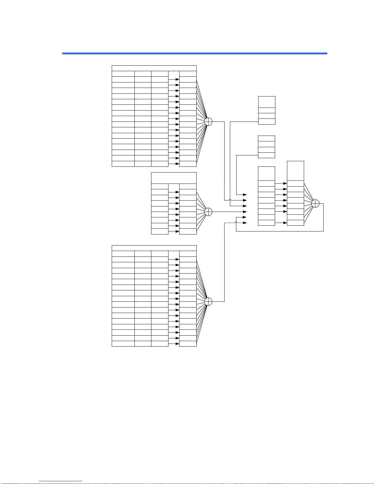
62
5-2. Configuration status register
Condition
OV (Over-Voltage) 0
PTR/NTR Event Enable
OC (Over-Current) 1
Not Used 2
POW (AC Power Off) 3
OT (Over-Temperature) 4
Not Used 5
Not Used 6
Not Used 7
VL (Voltage-Limit) 8
CL (Current-Limit) 9
Not Used 10
SD (Shutdown Alarm) 11
Power-Limit 12
SA (Sense Alarm) 13
IS (Instrument Summary) 14
Not Used 15
0
1
2
3
4
5
6
7
8
9
10
11
12
13
14
15
0
1
2
3
4
5
6
7
8
9
10
11
12
13
14
15
0
1
2
3
4
5
6
7
8
9
10
11
12
13
14
15
Condition
CAL (Calibration mode) 0
PTR/NTP Event Enable
Not Used 1
Not Used 2
Not Used 3
Not Used 4
WTG (Waiting for Trigger) 5
Not Used 6
Not Used 7
CV (Constant Voltage Mode) 8
Not Used 9
CC (Constant Current Mode) 10
OND (Output ON Delay) 11
OFD (Output OFF Delay) 12
Not Used 13
PR (Program Running) 14
Not Used 15
0
1
2
3
4
5
6
7
8
9
10
11
12
13
14
15
0
1
2
3
4
5
6
7
8
9
10
11
12
13
14
15
0
1
2
3
4
5
6
7
8
9
10
11
12
13
14
15
OPC (Operation Complete)
RQC (Request Control)
QUE (Query Error)
DDE (Device Dependent Error)
EXE (Execution Error)
CME (Command Error)
URQ (User Request)
PON (Power On)
0
1
2
3
4
5
6
7
0
1
2
3
4
5
6
7
0
1
2
3
4
5
6
7
ERR
QUES
MAV
ESB
OPER
0
1
2
3
4
5
6
7
Output
Buffer
:
:
:
Error Que
:
:
:
EnableEvent
Status
Byte
Register
Service
Request
Enable
Register
Questionable Status Register
Operation Status Register
Standard Event Status
Register
MSS
Page 69
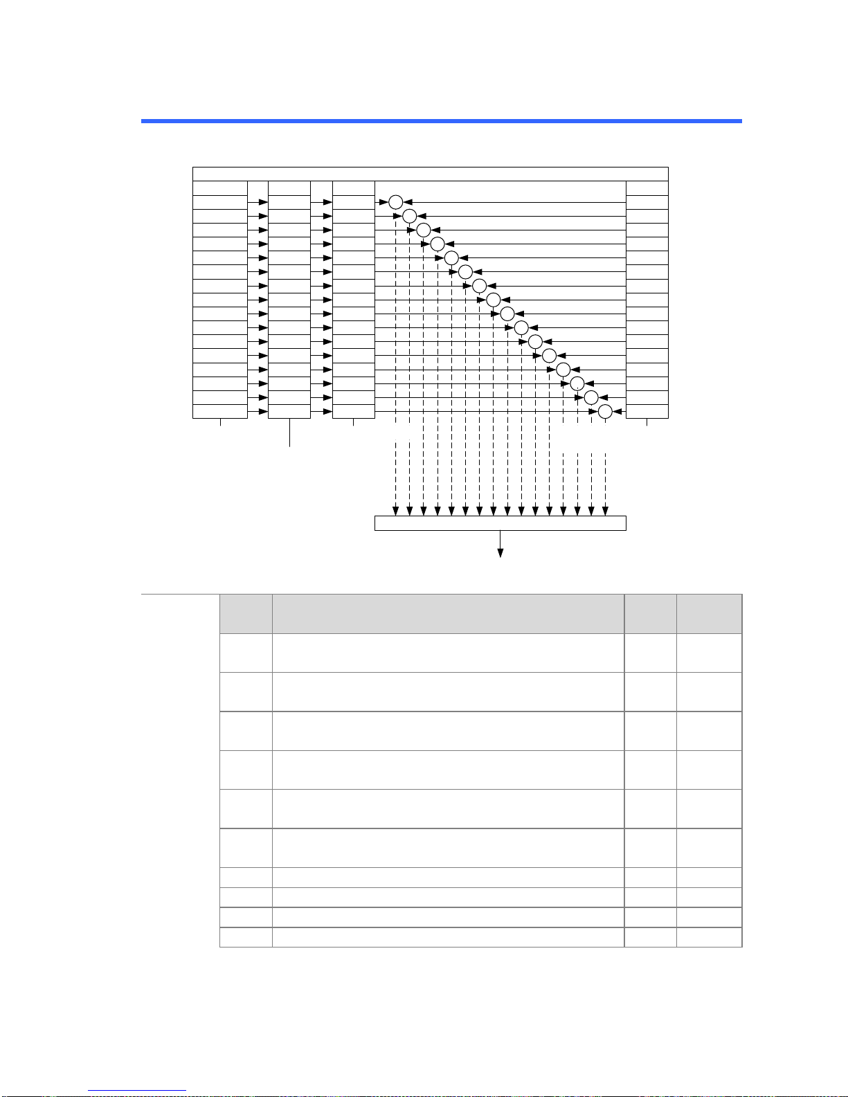
63
5-3. Questionable Status Register Group
Overview
The Questionable Status Register Group indicates if any protection
modes or limits have been tripped.
Condition
OV 0
Event Enable
OC 1
Not Used 2
POW 3
OT 4
Not Used 5
Not Used 6
Not Used 7
VL 8
CL 9
Not Used 10
SD 11
PL 12
SA 13
IS 14
Not Used 15
0
1
2
3
4
5
6
7
8
9
10
11
12
13
14
15
0
1
2
3
4
5
6
7
8
9
10
11
12
13
14
15
Questionable Status Register
&
&
&
&
&
&
&
&
&
&
&
&
&
&
&
&
Logical OR
To Ques in Status Byte Register
STATus:QUEStionable:CONDition? STATus:QUEStionable:EVENt?
STATus:QUEStionable:NTRansition <NRf>
STATus:QUEStionable:NTRansition?
STATus:QUEStionable:PTRansition <NRf>
STATus:QUEStionable:PTRansition?
STATus:QUEStionable:ENABle <NRf>
STATus:QUEStionable:ENABle?
PTR/NTR
0
1
2
3
4
5
6
7
8
9
10
11
12
13
14
15
Bit
Summary
Bit
name
Event
Bit #
Bit
Weight
OV
Over-Voltage
Over voltage protection has been tripped
0
1
OC
Over-Current
Over current protection has been tripped
1
2
POW
AC Power Off
AC power switch is off
3
8
OT
Over Temperature
Over temperature protection has been tripped
4
16
VL
Voltage Limit
Voltage limit has been reached
8
256
CL
Current Limit
Current limit has been reached
9
512
SD
Shutdown Alarm
11
2048
PL
Power-Limit
12
4096
SA
Sense Alarm
13
8192
IS
Insturument Summary
14
16384
Page 70

64
Condition
Register
The Questionable Status Condition Register indicates the status
of the power supply. If a bit is set in the Condition register, it
indicates that the event is true. Reading the condition register
does not change the state of the condition register.
PTR/NTR
Filters
The PTR/NTR (Positive/Negative transition) register determines
the type of transition conditions that will set the corresponding bit
in the Event Registers. Use the Positive transition filter to view
events that change from false to positive, and use the negative
transition filter to view events that change from positive to
negative.
Positive Transition
Negative Transition
0→1
1→0
Event
Register
The PTR/NTR Register will dictate the type of transition
conditions will set the corresponding bits in the Event Register. If
the Event Register is read, it will be cleared to 0.
Enable
Register
The Enable register determines which Events in the Event
Register will be used to set the QUES bit in the Status Byte
Register.
Page 71
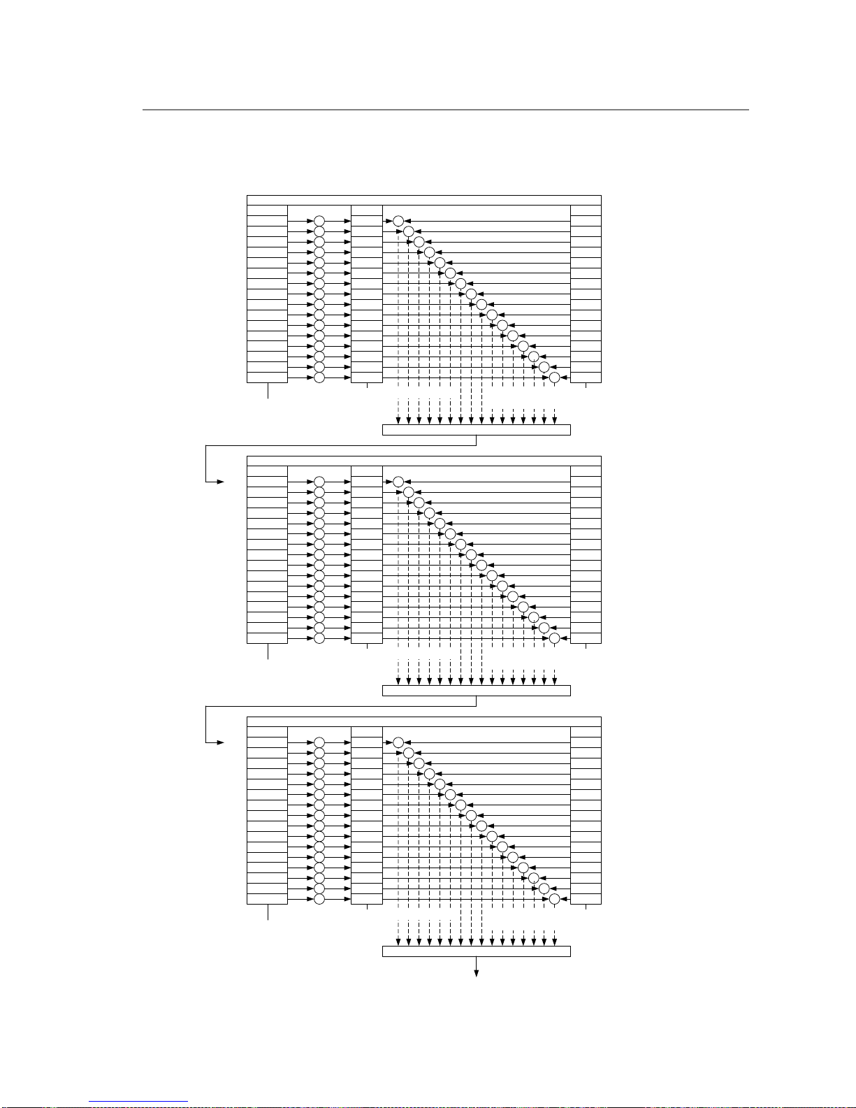
65
Instrument
Summary
Registers
The Instrument Summary Registers indicate if the protection
mode or limit of any of the instruments connected in Multi-Drop
mode has been tripped.
Condition
0 0
Event Enable
SRQ28 1
SRQ29 2
SRQ30 3
0 4
0 5
0 6
0 7
0 8
0 9
0 10
0 11
0 12
0 13
0 14
0 15
0
1
2
3
4
5
6
7
8
9
10
11
12
13
14
15
0
1
2
3
4
5
6
7
8
9
10
11
12
13
14
15
ISUM3
&
&
&
&
&
&
&
&
&
&
&
&
&
&
&
&
Logical OR
+
+
+
+
+
+
+
+
+
+
+
+
+
+
+
+
Condition
ISUM3 0
Event Enable
SRQ14 1
SRQ15 2
SRQ16 3
SRQ17 4
SRQ18 5
SRQ19 6
SRQ20 7
SRQ21 8
SRQ22 9
SRQ23 10
SRQ24 11
SRQ25 12
SRQ26 13
SRQ27 14
0 15
0
1
2
3
4
5
6
7
8
9
10
11
12
13
14
15
0
1
2
3
4
5
6
7
8
9
10
11
12
13
14
15
ISUM2
&
&
&
&
&
&
&
&
&
&
&
&
&
&
&
&
Logical OR
+
+
+
+
+
+
+
+
+
+
+
+
+
+
+
+
Condition
ISUM2 0
Event Enable
SRQ0 1
SRQ1 2
SRQ2 3
SRQ3 4
SRQ4 5
SRQ5 6
SRQ6 7
SRQ7 8
SRQ8 9
SRQ9 10
SRQ10 11
SRQ11 12
SRQ12 13
SRQ13 14
0 15
0
1
2
3
4
5
6
7
8
9
10
11
12
13
14
15
0
1
2
3
4
5
6
7
8
9
10
11
12
13
14
15
ISUM1
&
&
&
&
&
&
&
&
&
&
&
&
&
&
&
&
Logical OR
+
+
+
+
+
+
+
+
+
+
+
+
+
+
+
+
To Instrument Summary in Questionable Condition register (bit 14)
:STATus:QUEStionable:INSTrument:ISUMmary3:CONDition?
:STATus:QUEStionable:INSTrument:ISUMmary3[:EVENt]?
:STATus:QUEStionable:INSTrument:ISUMmary3:ENABle <NR1>
:STATus:QUEStionable:INSTrument:ISUMmary3:ENABle?
:STATus:QUEStionable:INSTrument:ISUMmary2:CONDition?
:STATus:QUEStionable:INSTrument:ISUMmary2[:EVENt]?
:STATus:QUEStionable:INSTrument:ISUMmary2:ENABle <NR1>
:STATus:QUEStionable:INSTrument:ISUMmary2:ENABle?
:STATus:QUEStionable:INSTrument:ISUMmary1:CONDition?
:STATus:QUEStionable:INSTrument:ISUMmary1[:EVENt]?
:STATus:QUEStionable:INSTrument:ISUMmary1:ENABle <NR1>
:STATus:QUEStionable:INSTrument:ISUMmary1:ENABle?
Page 72
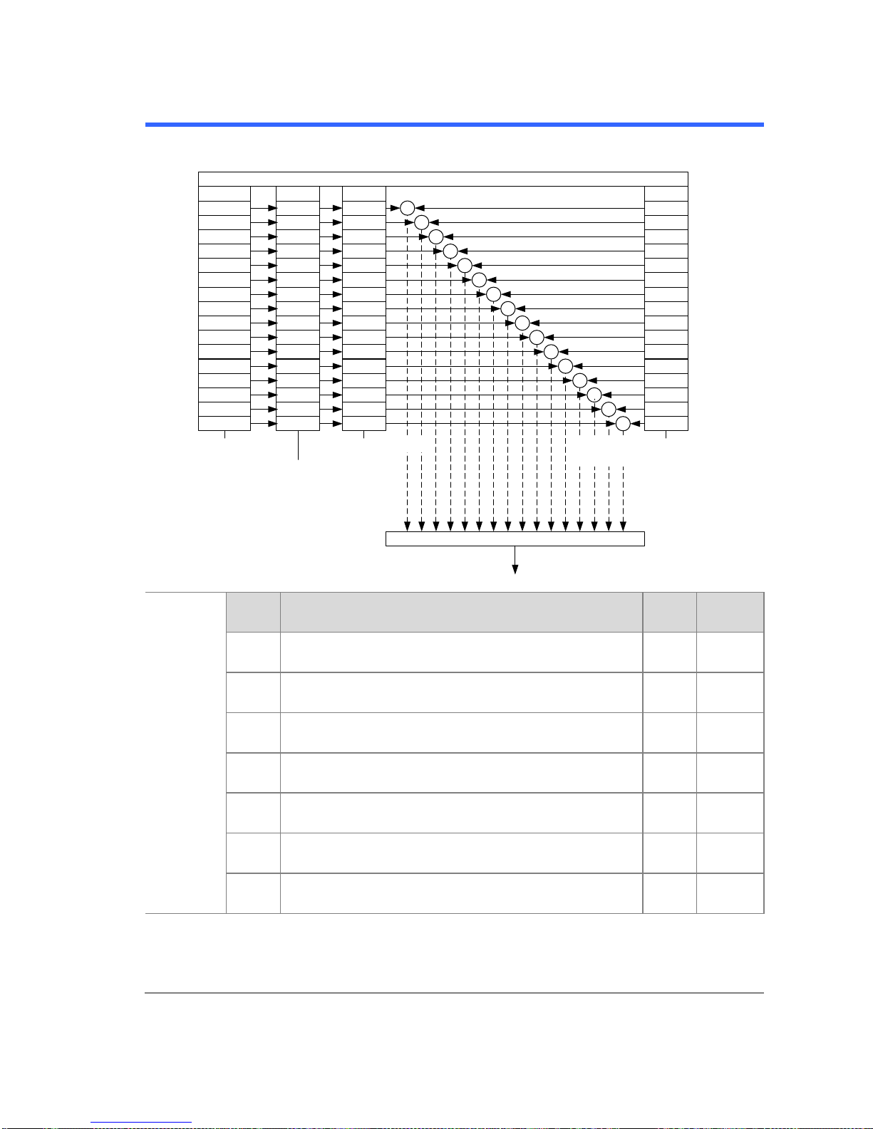
66
5-4. Operation Status Register Group
Overview
The Operation Status Register Group indicates the operating status of
the power supply.
CAL
Not Used
Not Used
Not Used
Not Used
WTG
Not Used
Not Used
CV
Not Used
CC
OND
OFD
Not Used
PR
Not Used
PTR/NTR Event Enable
0
1
2
3
4
5
6
7
8
9
10
11
12
13
14
15
0
1
2
3
4
5
6
7
8
9
10
11
12
13
14
15
0
1
2
3
4
5
6
7
8
9
10
11
12
13
14
15
Operation Status Register
&
&
&
&
&
&
&
&
&
&
&
&
&
&
&
&
Logical OR
To OPER in Status Byte Register
STATus:OPERation:CONDition? STATus:OPERation:EVENt?
STATus:OPERation:NTRansition <NRf>
STATus:OPERation:NTRansition?
STATus:OPERation:PTRansition <NRf>
STATus:OPERation:PTRansition?
STATus:OPERation:ENABle <NRf>
STATus:OPERation:ENABle?
Condition
0
1
2
3
4
5
6
7
8
9
10
11
12
13
14
15
Bit
Summary
Bit
name
Event
Bit #
Bit
Waight
CAL
Calibration mode
Indicates if the PFR-100 is in calibration mode.
0
1
WTG
Waiting for trigger
Indicates if the PFR-100 is waiting for a trigger.
5
32
CV
Constant voltage mode
Indicates if the PFR-100 is in CV mode.
8
256
CC
Constant current mode
Indicates if the PFR-100 is in CC mode.
10
1024
OND
Output ON Delay
Indicates if Output ON delay time is active
11
2048
OFD
Output OFF Delay
Indicates if Output OFF delay time is active
12
4096
PR
Program Running
Indicates if a Test is running
13
8192
Condition
Register
The Operation Status Condition Register indicates the operating
status of the power supply. If a bit is set in the Condition register, it
indicates that the event is true. Reading the condition register does
not change the state of the condition register.
Page 73
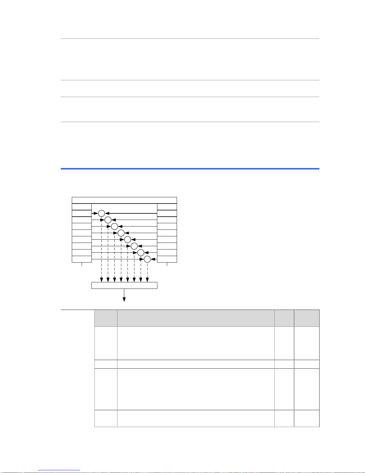
67
PTR/NTR
Filters
The PTR/NTR (Positive/Negative transition) register determines the
type of transition conditions that will set the corresponding bit in the
Event Registers. Use the Positive transition filter to view events that
change from false to positive, and use the negative transition filter to
view events that change from positive to negative.
Positive Transition
Negative Transition
0→1
1→0
Event
Register
The PTR/NTR Register will dictate the type of transition conditions
will set the corresponding bits in the Event Register. If the Event
Register is read, it will be cleared to 0.
Enable
Register
The Enable register determines which registered Events in the Event
Register will be used to set the OPER bit in the Status Byte Register.
When the Enable register is 0, the OPER bit is not set.
5-5. Standard Event Status Register Group
Overview
The Standard Event Status Register Group indicates if any errors have
occurred. The bits of the Event register are set by the error event
queue.
OPC
RQC
QUE
DDE
EXE
CME
URQ
PON
Event Enable
0
1
2
3
4
5
6
7
0
1
2
3
4
5
6
7
Standard Event Status Register
&
&
&
&
&
&
&
&
To ESB in Status Byte Register
*ESR?
Logical OR
*ESE <NRf>
*ESE?
Bit
Summary
Bit
name
Event
Bit #
Bit
Weight
OPC
Operation complete
The OCP bit is set when all selected pending
operations are complete. This bit is set in
response to the *OPC command.
0
1
RQC
Request control
1
2
QUE
Query Error
The Query Error bit is set in response to an error
reading the Output Queue. This can be caused
by trying to read the Output Queue when there is
no data present.
2
4
DDE
Device Dependent Error
Device specific error.
3
8
Page 74
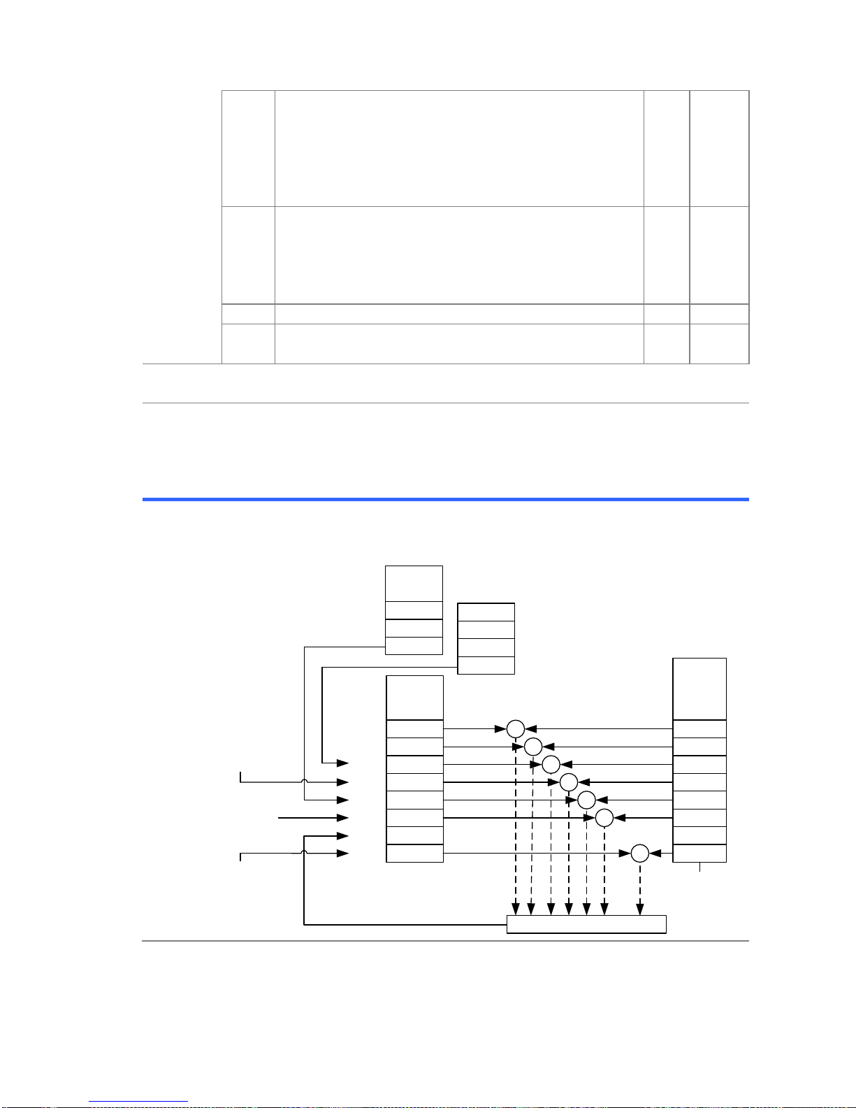
68
EXE
Execution Error
The EXE bit indicates an execution error due to
one of the following: illegal command parameter,
parameter out of range, invalid parameter, the
command didn’t execute due to an overriding
operation condition.
4
16
CME
Command Error
The CME bit is set when a syntax error has
occurred. The CME bit can also be set when a
<GET> command is received within a program
message.
5
32
URQ
User Request
6
64
PON
Power On
Indicates the power is turned on.
7
128
Event
Register
Any bits set in the event register indicate that an error has occurred.
Reading the Event register will reset the register to 0.
Enable
Register
The Enable register determines which Events in the Event Register will
be used to set the ESB bit in the Status Byte Register.
5-6. Status Byte Register & Service Request Enable Register
Overview
The Status Byte register consolidates the status events of all the status
registers. The Status Byte register can be read with the *STB? query
and can be cleared with the *CLS command.
ERR
QUES
MAV
ESB
MSS
OPER
0
1
2
3
4
5
6
7
Output
Buffer
:
:
:
Error Que
:
:
:
Status
Byte
Register
0
1
2
3
4
5
6
7
&
&
&
&
&
&
&
*SRE <NRf>
*SRE?
Service
Request
Enable
Register
Logical OR
*STB?
From
Questionable
Status Register
From Standard
Event Status
Register
From
Operation
Status Register
Page 75

69
Bit
Summary
Bit
name
Event
Bit #
Bit
Weight
ERR
Error Event/Quere
If data is present in the Error queue, the ERR
bit will be set.
2 4 QUES
Questionable Status Register
The summary bit for the Questionable Status
Register group.
3
8
MAV
Message Available
This is set when there is data in the Output
Queue waiting to be read.
4
16
ESB
Event Summary Bit
The ESB is the summary bit for the Standard
Event Status Register group.
5
32 MSS
The MSS Bit is the summary of the Status
Byte Register and Service Request register
(bits 1-5, 7). This will be set to 1.
6
64 OPER
Operation Status Register
OPER bit is the summary bit for the Operation
Status Register Group.
7
128
Status Byte
Register
Any bits set in the Status byte register acts as a summary register for
all the three other status registers and indicates if there is a service
request, an error in the Error Queue or data in the Output Queue.
Reading the Status Byte register will reset the register to 0.
Service
Request
Enable
Register
The Service Request Enable Register controls which bits in the
Status Byte Register are able to generate service requests.
5-7. Error list
5-7-1. Command Errors
Overview
An <error / event number> in the range [-199, -100] indicates that
an IEEE 488.2 syntax error has been detected by the instrument’s
parser. The occurrence of any error in this class shall cause the
command error bit (bit 5) in the event status register (IEEE 488.2,
section 11.5.1) to be set. One of the following events has occurred:
An IEEE 488.2 syntax error has been detected by the parser. That
is, a controller-to-device message was received which is in violation
of the IEEE 488.2 standard. Possible violations include a data
element which violates the device listening formats or whose type
is unacceptable to the device.
An unrecognized header was received. Unrecognized headers
include incorrect device-specific headers and incorrect or
unimplemented IEEE 488.2 common commands.
Events that generate command errors shall not generate execution
errors, device-specific errors, or query errors; see the other error
definitions in this chapter.
Page 76

70
Error code
Description
-100
Command error
This is the generic syntax error for devices that
cannot detect more specific errors. This code
indicates only that a Command Error as defined in
IEEE 488.2, 11.5.1.1.4 has occurred.
-102
Syntax error
An unrecognized command or data type was
encountered; for example, a string was received
when the device does not accept strings.
-103
Invalid
separator
The parser was expecting a separator and
encountered an illegal character; for example, the
semicolon was omitted after a program message
unit,
MEAS:VOLT:DC?:MEAS:CURR:DC?
-104
Data type error
The parser recognized a data element different than
one allowed; for example, numeric or string data was
expected but block data was encountered.
-108
Parameter not
allowed
More parameters were received than expected for
the header; for example, the KLOCk command only
accepts one parameter, so receiving
“:SYSTem:KLOCk 1,0” is not allowed.
-109
Missing
parameter
Fewer parameters were received than required for
the header; for example, the KLOCk command
requires one parameter, so receiving “KLOCk” is not
allowed.
-111
Header
separator error
A character which is not a legal header separator
was encountered while parsing the header; for
example, no white space followed the header, thus
*SRE2 is an error.
-112
Program
mnemonic too
long
The header contains more that twelve characters
(see IEEE 488.2, 7.6.1.4.1).
-113
Undefined
header
The header is syntactically correct, but it is
undefined for this specific device; for example, *XYZ
is not defined for any device.
-114
Header suffix
out of range
The value of a numeric suffix attached to a program
mnemonic, see Syntax and Style section 6.2.5.2,
makes the header invalid.
-115
Unexpected
number of
parameters
The number of parameters received does not
correspond to the number of parameters expected.
This is typically due an inconsistency with the
number of instruments in the selected group.
-120
Numeric data
error
This error, as well as errors -121 through -129, are
generated when parsing a data element which
appears to be numeric, including the nondecimal
numeric types. This particular error message should
be used if the device cannot detect a more specific
error.
Page 77

71
-121
Invalid
character in
number
An invalid character for the data type being parsed
was encountered; for example, an alpha in a decimal
numeric or a “9" in octal data.
-128
Numeric data
not allowed
A legal numeric data element was received, but the
device does not accept one in this position for the
header.
-131
Invalid suffix
The suffix does not follow the syntax described in
IEEE 488.2, 7.7.3.2, or the suffix is inappropriate for
this device.
-141
Invalid
character data
Either the character data element contains an invalid
character or the particular element received is not
valid for the header.
-148
Character data
not allowed
A legal character data element was encountered
where prohibited by the device.
-151
Invalid string
data
A string data element was expected, but was invalid
for some reason (see IEEE 488.2, 7.7.5.2); for
example, an END message was received before the
terminal quote character.
-158
String data not
allowed
A string data element was encountered but was not
allowed by the device at this point in parsing.
-160
Block data error
This error, as well as errors -161 through -169, are
generated when parsing a block data element. This
particular error message should be used if the
device cannot detect a more specific error.
-161
Invalid block
data
A block data element was expected, but was invalid
for some reason (see IEEE 488.2, 7.7.6.2); for
example, an END message was received before the
length was satisfied.
-168
Block data not
allowed
A legal block data element was encountered but was
not allowed by the device at this point in parsing.
-178
Expression data
not allowed
A legal expression data was encountered but was
not allowed by the device at this point in parsing.
5-7-2. Execution Errors
Overview
An <error/event number> in the range [ -299 , -200 ] indicates that
an error has been detected by the instrument’s execution control
block. The occurrence of any error in this class shall cause the
execution error bit (bit 4) in the event status register (IEEE 488.2,
section 11.5.1) to be set. One of the following events has occurred:
A <PROGRAM DATA> element following a header was evaluated
by the device as outside of its legal input range or is otherwise
inconsistent with the device’s capabilities.
A valid program message could not be properly executed due to
some device condition.
Page 78

72
Execution errors shall be reported by the device after rounding and
expression evaluation operations have taken place. Rounding a
numeric data element, for example, shall not be reported as an
execution error. Events that generate execution errors shall not
generate Command Errors, device-specific errors, or Query Errors;
see the other error definitions in this section.
Error code
Description
-200
Execution error
This is the generic syntax error for devices that
cannot detect more specific errors. This code
indicates only that an Execution Error as defined in
IEEE 488.2, 11.5.1.1.5 has occurred.
-201
Invalid while in
local
Indicates that a command is not executable while
the device is in local due to a hard local control (see
IEEE 488.2, 5.6.1.5); for example, a device with a
rotary switch receives a message which would
change the switches state, but the device is in local
so the message cannot be executed.
-203
Command
protected
Indicates that a legal password-protected program
command or query could not be executed because
the command was disabled.
-211
Trigger ignored
Indicates that a GET, *TRG, or triggering signal was
received and recognized by the device but was
ignored because of device timing considerations; for
example, the device was not ready to respond. Note:
a DT0 device always ignores GET and treats *TRG
as a Command Error.
-213
Init ignored
Indicates that a request for a measurement initiation
was ignored as another measurement was already
in progress.
-220
Parameter error
Indicates that a program data element related error
occurred. This error message should be used when
the device cannot detect the more specific errors
described for errors -221 through -229.
-221
settings conflict
Indicates that a legal program data element was
parsed but could not be executed due to the current
device state (see IEEE 488.2, 6.4.5.3 and
11.5.1.1.5.).
-222
Data out of
range
Indicates that a legal program data element was
parsed but could not be executed because the
interpreted value was outside the legal range as
defined by the device (see IEEE 488.2, 11.5.1.1.5.).
-224
Illegal
parameter
value
This parameter can not be specified.
Page 79

73
5-7-3. Device Specific Errors
Overview
An <error/event number> in the range [ -399 , -300 ] or [ 1 , 32767 ]
indicates that the instrument has detected an error which is not a
command error, a query error, or an execution error; some device
operations did not properly complete, possibly due to an abnormal
hardware or firmware condition. These codes are also used for
self-test response errors. The occurrence of any error in this class
should cause the device-specific error bit (bit 3) in the event status
register (IEEE 488.2, section 11.5.1) to be set. The meaning of
positive error codes is device-dependent and may be enumerated
or bit mapped; the <error message>string for positive error codes is
not defined by SCPI and available to the device designer.
Note that the string is not optional; if the designer does not wish to
implement a string for a particular error, the null string should be
sent (for example, 42,""). The occurrence of any error in this class
should cause the device-specific error bit (bit 3) in the event status
register (IEEE 488.2, section 11.5.1) to be set. Events that
generate device-specific errors shall not generate command errors,
execution errors, or query errors; see the other error definitions in
this section.
Error code
Description
-310
System error
Indicates that some error, termed “system error” by
the device, has occurred. This code is
device-dependent.
-320
Storage fault
Indicates that the firmware detected a fault when
using data storage. This error is not an indication of
physical damage or failure of any mass storage
element.
5-7-4. Query Errors
Overview
An <error/event number> in the range [ -499 , -400 ] indicates that
the output queue control of the instrument has detected a problem
with the message exchange protocol described in IEEE 488.2,
chapter 6. The occurrence of any error in this class shall cause the
query error bit (bit 2) in the event status register (IEEE 488.2, section
11.5.1) to be set. These errors correspond to message exchange
protocol errors described in IEEE 488.2, section 6.5. One of the
following is true:
An attempt is being made to read data from the output queue when
no output is either present or pending;
Events that generate query errors shall not generate command
errors, execution errors, or device-specific errors; see the other error
Page 80

74
definitions in this section.
Error code
Description
-400
Query error
This is the generic query error for devices
that cannot detect more specific errors. This
code indicates only that a Query Error as
defined in IEEE 488.2, 11.5.1.1.7 and 6.3 has
occurred.
Page 81

75
6. Appendix
6-1. Default Settings
The following default settings are the factory configuration settings for the power
supply.
Initial Settings
Default Setting
Output
OFF
Key lock
0 (Disabled)
Voltage setting
0 V
Current setting
0 A
OVP
Maximum
OCP
Maximum
UVL
0V
Normal Function Settings
Setting
Default Setting
Output ON delay time
F-01
0.00s
Output OFF delay time
F-02
0.00s
V-I mode slew rate select
F-03
0 = CV high speed priority
Rising voltage slew rate
F-04
100.0V/s (PFR-100L50)
500.0V/s (PFR-100M250)
Falling voltage slew rate
F-05
100.0V/s (PFR-100L50)
500.0V/s (PFR-100M250)
Rising current slew rate
F-06
20.00A/s (PFR-100L50)
4.000A/s (PFR-100M250)
Falling current slew rate
F-07
20.00A/s (PFR-100L50)
4.000A/s (PFR-100M250)
Bleeder circuit control
F-09
1 = ON
Buzzer ON/OFF control
F-10
1 = ON
Detection Time of OCP
F-12
0.0 sec
Current Setting limit
F-13
0 = OFF (The limit function of current
setting is disabled.)
Voltage Setting limit
F-14
0 = OFF (The limit function of voltage
setting is disabled.)
Memory Recall display
F-15
0 = OFF
Measurement average
setting
F-17
0 = Low
Lock Mode
F-19
0 =0: Lock Panel, Allow Output OFF
USB / GP-IB setting
Setting
Default Setting
GP-IB address
F-23
8
LAN setting
Setting
Default Setting
DHCP
F-37
1 = ON
Web password
enable / disable
F-60
1 = Enable
Web password
F-61
0000
UART setting
Setting
Default Setting
UART Baudrate
F-71
7 = 115200
UART Data Bits
F-72
1 = 8bits
Page 82

76
UART Parity
F-73
0 = None
UART Stop Bit
F-74
0 = 1bit
UART TCP
F-75
0 = SCPI
Power On Configuration
setting
Setting
Default Setting
CV Control
F-90
0 = Panel control (local)
CC Control
F-91
0 = Panel control (local)
Power ON Output
F-92
0 = Safe Mode (Output Off at startup)
External Output Logic Control
F-94
0 = High ON
The contents of the Test Mode are not cleared at initialization of F-88.
Clear the Delete Test Data.
The contents of the memory data (M1, M2, M3) are not cleared for F-88
initialization.
The Interface Select (F-29) setting is not initialized in F-88.
The UART address (F-76) and the Multi-drop control (F-77) settings are not
initialized in F-88.
6-2. Error Messages and other Messages
The following error messages or other messages may appear on the PFR-100
screen during operation.
Error Message
Description
OHP
Over temperature protection
SENSE ALARM1
Sense Alarm1
SENSE ALARM2
Sense Alarm2
AC
AC fail
OVP
Over voltage protection
OCP
Over current protection
SHUTDOWN
Force shutdown
Err 001
USB mass storage is not present
Err 002
No (such) file in USB mass storage
Err 003
Empty memory location
Err 004
File access error
Err 005
File size error
Err 007
Slave occurs Off-line (Multi-Drop mode)
Normal Messages
Description
MSG 001
External control of output. Output off
(F-94 = 0, High = on)
MSG 002
External control of output. Output off
(F-94 = 1, Low = on)
Communication
Interface Messages
Description
MS ON
Mass storage plugged into front USB port
MS OFF
Mass storage removed from front USB port
Page 83
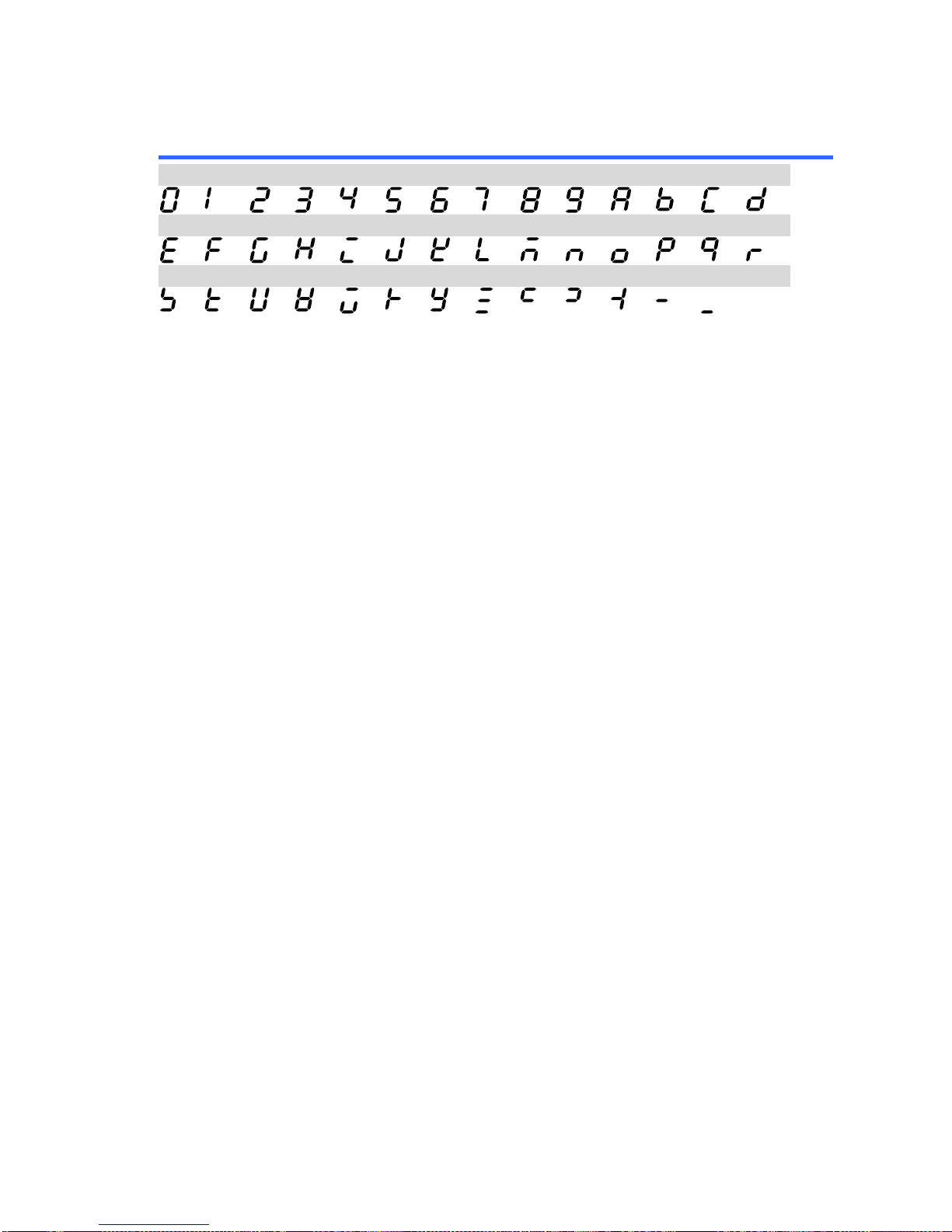
77
6-3. LED ASCII Table Character Set
Use the following table to read the LED display messages.
0 1 2 3 4 5 6 7 8 9 A B C
D
E F G H I J K L M N O P Q
R
S T U V W X Y Z ( ) + - ,
Page 84

7F Towa Fudosan Shin Yokohama Bldg.
2-18-13, Shin Yokohama, Kohoku-ku, Yokohama, Kanagawa, 222-0033 Japan
http://www.texio.co.jp
 Loading...