


B71-0086-01
INSTRUCTION MANUAL
REGULATED DC POWER SUPPLY
PD-AD SERIES
PD18-10AD PD18-20AD PD18-30AD
PD36-10AD PD36-20AD
PD56-6AD PD56-10AD
PD110-3AD PD110-5AD

■ About Brands and Trademarks
“TEXIO” is the product brand name of our industrial electronic devices.
All company names and product names mentioned in this manual are the
trademark or the registered trademark of each company or group in each
country and region.
■ About the Instruction Manual
Permission from the copyright holder is needed to reprint the contents of this
manual, in whole or in part. Be aware that the product specifications and the
contents of this manual are subject to change for the purpose of improvement.

CONTENTS
USING THE PRODUCT SAFELY ······················································ Ⅰ-Ⅳ
1. GENERAL..........................................................................1
2. FEATURES ........................................................................1
3. SPECIFICATIO.................................................................. 2
4. PRECAUTION FOR USE.................................................. 6
5. CONTROLS AND INDICATORS ....................................... 9
5-1. FRONT PANEL..........................................................................9
5-2. REAR P
ANEL .......................................................................... 11
6. OPERATION ................................................................... 12
6-1. As a constant-Voltage Power Supply.......................................12
6-2. As a Constant-Current Power Supply
......................................12
6-3. How to Check V
oltage and Current .........................................13
6-4. How to Set Overvoltage Protection (OVP) Level
.....................13
7. APPLICATION ................................................................. 14
7-1. Use of Rear-Panel Terminals...................................................14
7-2. Remote Sensing
......................................................................14
7-3. Remote Control of Constant-volt
age (Resistance, voltage) .....15
7-3-1. Control by resistance (Ⅰ)
.................................................16
7-3-2. Control by resistance (Ⅱ)
.................................................16
7-3-3. Control by ex
ternal voltage ...............................................18
7-4. Remote Control of Constant Current (Resist
ance, Voltage) ....18
7-4-1. Control by
resistance ........................................................18
7-4-2. Control by ex
ternal voltage ...............................................19
7-5. Series/Parallel Connection Operation
......................................20

7-5-1. Series connection
.............................................................20
7-5-2. How to determine external resist
ance R1 and R2.............22
7-5-3. Parallel connection
...........................................................22
7-6. Constant-Current Charging/Discharging of Battery
.................24
7-6-1. Constant-current charging
................................................24
7-7. Turning On and Off the Output Using External Contact Signals
........................................................................................................24
8. OPTIONAL ACCESSORIES............................................ 26
9. MAINTENANCE .............................................................. 26
10. TROUBLESHOOTING .................................................. 27
11. DIMENSIONS................................................................ 28
I
USING THE PRODUCT SAFELY
■ Preface
To use the product safely, read instruction manual to the end. Before using this product,
understand how to correctly use it. If you read the manuals but you do not understand
how to use it, ask us or your local dealer. After you read the manuals, save it so that
you can read it anytime as required.
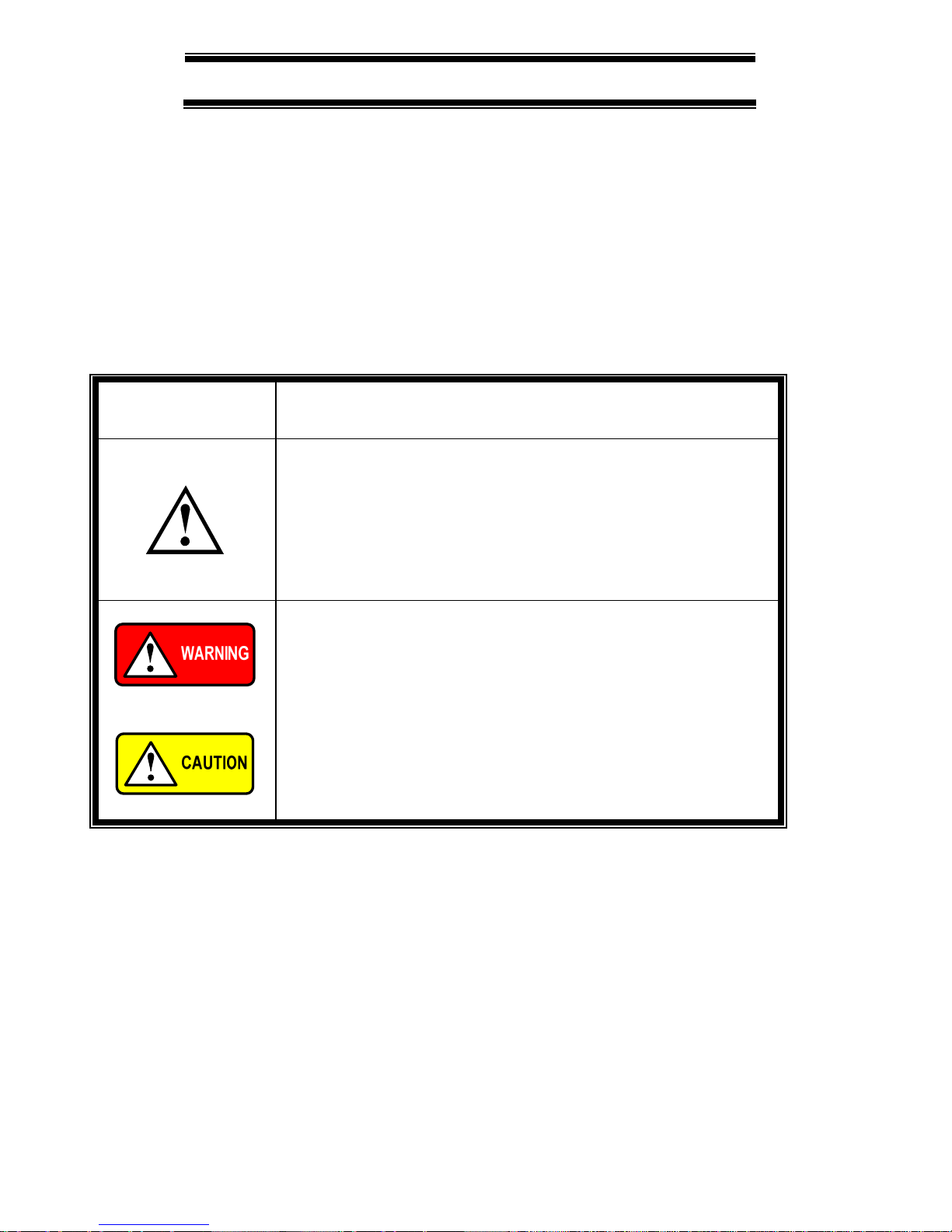
■ Pictorial indication
The manuals and product show the warning and caution items required to safely use the
product. The following pictorial indication is provided
.
Pictorial
indication
Some part of this product or the manuals may show this
pictorial indication. In this case, if the product is
incorrectly used in that part, a serious danger may be
brought about on the user's body or the product. To use
the part with this pictorial indication, be sure to refer to the
manuals.
If you use the product, ignoring this indication, you may get
killed or seriously injured. This indication shows that the
warning item to avoid the danger is provided.
If you incorrectly use the product, ignoring this indication,
you may get slightly injured or the product may be
damaged. This indication shows that the caution item to
avoid the danger is provided.
Please be informed that we are not responsible for any damages to the user or to the
third person, arising from malfunctions or other failures due to wrong use of the product
or incorrect operation, except such responsibility for damages as required by law.

II
USING THE PRODUCT SAFELY
■ Do not remove the product's covers and panels
Never remove the product's covers and panels for any purpose.
Otherwise, the user's electric shock or fire may be incurred.
■ Warning on using the product
Warning items given below are to avoid danger to user's body and life and avoid the
damage or deterioration of the product. Use the product, observing the following
warning and caution items.
■ Warning items on power supply
● Power supply voltage
The rated power supply voltages of the product are 100, 120, 220 and 240VAC. The
rated power supply voltage for each product should be confirmed by reading the label
attached on the back of the product or by the “rated” column shown in the instruction
manual. The specification of power cord attached to the products is rated to 125VAC
for all products which are designed to be used in the areas where commercial power
supply voltage is not higher than 125VAC. Accordingly, you must change the power
cord if you want to use the product at the power supply voltage higher than 125VAC. If
you use the product without changing power cord to 250VAC rated one, electric shock
or fire may be caused. When you used the product equipped with power supply
voltage switching system, please refer to the corresponding chapter in the instruction
manuals of each product.
● Power cord
(IMPORTANT) The attached power cord set can be used for this
device only.
If the attached power cord is damaged, stop using the product and call us or your
local dealer. If the power cord is used without the damage being removed, an
electric shock or fire may be caused.
● Protective fuse
If an input protective fuse is blown, the product does not operate. For a product with
external fuse holder, the fuse may be replaced. As for how to replace the fuse, refer
to the corresponding chapter in the instruction manual. If no fuse replacement
procedures are indicated, the user is not permitted to replace it. In such case, keep
the case closed and consult us or your local dealer. If the fuse is incorrectly
replaced, a fire may occur.

III
USING THE PRODUCT SAFELY
■ Warning item on Grounding
If the product has the GND terminal on the front or rear panel surface, be sure to ground
the product to safely use it.
■ Warnings on Installation environment
● Operating temperature and humidity
Use the product within the operating temperature indicated in the “rating” temperature
column. If the product is used with the vents of the product blocked or in high
ambient temperatures, a fire may occur. Use the product within the operating
humidity indicated in the “rating” humidity column. Watch out for condensation by a
sharp humidity change such as transfer to a room with a different humidity. Also, do
not operate the product with wet hands. Otherwise, an electric shock or fire may
occur.
● Use in gas
Use in and around a place where an inflammable or explosive gas or steam is
generated or stored may result in an explosion and fire. Do not operate the product
in such an environment. Also, use in and around a place where a corrosive gas is
generated or spreading causes a serious damage to the product. Do not operate the
product in such an environment.
● Installation place
Do not insert metal and inflammable materials into the product from its vent and spill
water on it. Otherwise, electric shock or fire may occur.
■ Do not let foreign matter in
Do not insert metal and inflammable materials into the product from its vent and spill
water on it. Otherwise, electric shock or fire may occur.
■ Warning item on abnormality while in use
If smoke or fire is generated from the product while in use, stop using the product, turn
off the switch, and remove the power cord plug from the outlet. After confirming that
no other devices catch fire, ask us or your local dealer.

IV
USING THE PRODUCT SAFELY
■ Input / Output terminals
Maximum input to terminal is specified to prevent the product from being damaged. Do
not supply input, exceeding the specifications that are indicated in the "Rating" column in
the instruction manual of the product. Also, do not supply power to the output terminals
from the outside. Otherwise, a product failure is caused.
■ Calibration
Although the performance and specifications of the product are checked under strict
quality control during shipment from the factory, they may be deviated more or less by
deterioration of parts due to their aging or others.
It is recommended to periodically calibrate the product so that it is used with its
performance and specifications stable. For consultation about the product calibration,
ask us or your local dealer.
■ Daily Maintenance
When you clean off the dirt of the product covers, panels, and knobs, avoid solvents
such as thinner and benzene. Otherwise, the paint may peel off or resin surface may
be affected. To wipe off the covers, panels, and knobs, use a soft cloth with neutral
detergent in it.
During cleaning, be careful that water, detergents, or other foreign matters do not get
into the product.
If a liquid or metal gets into the product, an electric shock and fire are caused.
During cleaning, remove the power cord plug from the outlet.
Use the product correctly and safely, observing the above warning and caution items.
Because the instruction manual indicates caution items even in individual items, observe
those caution items to correctly use the product.
If you have questions or comments about the manuals, ask us or E-Mail us.

1
1. GENERAL
The PD-AD series are compact DC power supplies regulated by phase control. They have
sufficient reliability and accurate electrical characteristics and are suitable for research,
experiments, aging of many hours, and for control, etc. They are provided also with means
of protection and remote control. They are designed totally for the ease of use.
2. FEATURES
○ The size is compact owing to the built-in phase-controlled preregulator.
○ Characteristics of voltage regulation and against noises in-cluding ripples are very
good.
○ Both voltage and current vary little with temperature.
○ The output voltage and output current may be changeable in small steps with a
potentiometer turnable as many as ten positions.
○ The V/I CHECK switch provided permits to check the preset values of voltage and
current even during operation.
○ The OUTPUT switch turns on and off the output.
○ The use of the external contact allows the output to be turned on and off from outside.
○ Protection is complete from overvoltage, overcurrent, and excessive temperature rise.
The OVP CHECK function provided permits to preset the overvoltage protection level
and check the preset level during operation.
○ Master / slave control is possible by series and parallel connections.
○ The output voltage and current may be remote-controlled using an external resistance
or external signals.
○ Rapid transient characteristics are good.

2
3. SPECIFICATIO
Model PD PD18-10AD PD18-20AD PD18-30AD PD36-10AD PD36-20AD PD56-6AD PD56-10AD PD110-3AD PD110-5AD
Output
Output voltage 10-positions 0 to 18V 0 to 36V 0 to 56V 0 to 110V
Resolution (theoretical) 3.1mV 6.2mV 9.6mV 18.7mV
Output current 10-positions 0 to 10A 0 to 20A 0 to 30A 0 to 10A 0 to 20A 0 to 6A 0 to 10A 0 to 3A 0 to 5A
Resolution (theoretical) 1.7mA 3.4mA 5.1mA 1.7mA 3.4mA 1.02mA 1.7mA 0.51mA 0.85mA
Constant –voltage characteristics (CV)
Input regulation *1
(for AC±10% fluctuation)
0.005%+1mV
Load regulation *1
(for 0 to 100% fluctuation)
0.005%+1mV 0.005%+2mV 0.005%+1mV 0.005%+2mV 0.005%+1mV 0.005%+2mV 0.005%+1mV
Ripples / noises *2
(10Hz to 1MHz) rms
0.5mVrms 1mVrms
Transient response
(standard value)
50μsec
(Typical)
100μsec(Typical)
50μsec
(Typical)
100μsec
(Typical)
50μsec(Typical)
Temperature characteristics
(standard value)
100PPM/℃(Typical)
Remote control
resistance/voltage
Approx. 0 to 10kΩ/0 to 10V
Constant-current characteristics (CC)
Input regulation *1
(for AC±10% fluctuation)
1mA 5mA 1mA 5mA 1mA 3mA 1mA
Load regulation *1
(for 0 to 100% fluctuation)
5mA
Ripples / noises *2
(10Hz to 1MHz) rms
3mArms 10mArms 3mArms 10mArms 2mArms 3mArms 1mArms
Remote control
resistance/voltage
Approx. 0 to 10kΩ/0 to 10V
3
Model PD PD18-10AD PD18-20AD PD18-30AD PD36-10AD PD36-20AD PD56-6AD PD56-10AD PD110-3AD PD110-5AD
Protection
Operation Turn off power switch
Temperature detection 100℃
Overvoltage protection level
(standard value)
15 to 110% of rated output voltage
Input fuse (at AC 100V) 7A 15A 20A 12A 20A 10A 15A 10A 15A
Meter and indications
Voltage at digital display
(Auto range)
3-1/2 digits 19.99V, 199.9V, (F.S) two ranges ± (0.1%rdg + 1 digit) 23℃±5℃, Less than 80% RH
D type
Current at digital display
(Fix, range)
3-1/2 digits 19.99A,
(F.S) ± (0.5%rdg +
1 digit) 23℃±5 ℃ ,
Less than 80% RH
3 digits 99.9A(F.S),
± (0.5%rdg + 1 digit) 23℃±
5℃, Less than 80% RH
3-1/2 digits 19.99A
(F.S) ± (0.5%rdg +
1 digit) 23℃±5℃ ,
Less than 80% RH
3 digits 99.9A(F.S),
± (0.5%rdg + 1 digit)
23℃±5℃, Less than
80% RH
3-1/2 digits 19.99A, (F.S) ± (0.5%rdg + 1 digit) 23℃±5℃, Less than
80% RH
Indication of constant
Voltage operation
CV green LED lights
Indication of constant
Current operation
CC red LED lights
Indication of output OUTPUT red LED lights when turned on
Function
Output switch Turns on and off output
Voltage/current check switch Preset voltage and current indicated with meters during on time
Overvoltage protection
(OVP) preset
Indicates the over voltage protection level on the voltmeters during on time
Remote sensing Via the rear panel sensor terminal

4
Model PD PD18-10AD PD18-20AD PD18-30AD PD36-10AD PD36-20AD PD56-6AD PD56-10AD PD110-3AD PD110-5AD
Series control Master / slave control
Parallel control Master / slave control
Operating conditions
Temperature 0℃ to 40℃
Humidity Less than 80%
Cooling Fan
Output polarity Positive or negative side grounded
Withstand voltage to ground ±250VDC
Insulation resistance
Chassis – input line 30MΩ or more at 500VD C
Chassis – output line 20MΩ or more at 500VDC
Power supply
Input voltage AC100V/120V/200V/220V/240V±10% (Max. 250VAC) 50/60Hz 1φ
Approx.360W Approx.620W Approx.1kW Approx.560W Approx.1kW Approx.500W Approx.800W Approx.500W Approx.800W
Power consumption
(at AC 100V)
Approx.530VA Approx.1kVA Approx.1.5kVA Approx.830VA Approx.1.6kVA Approx.800VA Approx.1250VA Approx.800VA Approx.1250VA
Dimension and weight
(W) 208
(H) 147
Enclosure
Dimensions
(mm)
(D) 300 420 457 300 420 300 348 300 348

5
Model PD PD18-10AD PD18-20AD PD18-30AD PD36-10AD PD36-20AD PD56-6AD PD56-10AD PD110-3AD PD110-5AD
(W) 208
(H) 168
Maximum
Dimensions
(mm)
(D)
(including power
input connector)
346
(355)
483
(486)
520
(523)
346
(361)
483
(486)
346
(361)
394
(409)
346
(361)
394
(409)
Weigh Approx. 13kg Approx. 19kg Approx. 24kg Approx. 14kg Approx. 23kg Approx. 14kg Approx. 18kg Approx. 14kg Approx. 18kg
Accessories
Instruction manual CD-ROM
100V,120V area 2 or 3-core
AC cable(2m)
2 or 3-core AC cable(2 or 2.5m)
Input power
code
200V,220V,240V
area
3-core AC cable(2m)
3-core AC
cable(2.5m)
3-core AC
cable(2m)
3-core AC
cable(2.5m)
3-core AC cable(2m)
100V,120V area None 1 1 1 1 1 1 1 1 Connector
retainer
200V,220V,240V
area
None None 1 None 1 None None None None
100V,120V area 7A×1 None None 12A×1 None 10A×1 15A×1 10A×1 15A×1 Replacement
fuse
200V,220V,240V
area
4A×1 None None 6A×1 None 5A×1 8A×1 5A×1 8A×1
*1 Measured via the sensing terminal.
*2 Measured with plus or minus grounded.
■ Circuit and ratings are subject to change to without notice to developments in technology.

6
4. PRECAUTION FOR USE
Never detach the case or panel from this product. Detaching the case or panel may cause
damages to this product or electrocution or other dangerous accidents to the use.
1) CHECKING INPUT VOLTAGE
① Keep the permitted range of input voltage. Single phase, 100/120/200/220/
240 V AC, ±10%, 50/60 Hz.
② The rated input voltage of this product is adjusted before shipment. It cannot be changed
by the user.
If it is necessary to change the rated input voltage of this product, please contact your
dealer or our distributor.
③ Each model having the rated output not less than 20 A has a built-in protection fuse. The
user cannot replace the fuse in a model having 20 A or more output rating. If the fuse
blows out and needs to be replaced, please contact your dealer or our distributor.

7
2) POWER CORD CONNECTION
Some models have a connector retainer on the AC cord connector to hold the cord from
slipping off.
For safe operation, be sure the retainer is locked.
PD18-30AD, PD36-20AD are cannot connect with a commercial AC power inlet because
those current ratings are larger than same of the AC power source.
Process the attached unterminated cord shown below and connect it to an appropriate AC
power source.
In that case, wiring work must be done by either an electric engineer or a qualified person.
L N GND
1 BLACK WHITE GREEN
2 BROWN BLUE GREEN/YELLOW
*The color combination is ether item 1 or item 2.
1) OUTPUT CONNECTION
① Make sure that the rear-panel output terminals and control terminals are connected
with jumpers as shown Fig. 2.
Output terminals of rear panel
Fig . 2
L
GND
N
--S +
+S
①②③④⑤⑥⑦⑧⑨⑩⑪⑫
Control terminals
Fig. 1

8
② The output lines are floating. Connect either of the front-panel output terminals to GND
normally with short bar.
2) ENVIRONMENTAL CONDITIONS
① Keep the operating temperature range of 0℃ to 40℃.It the ambient temperature rises
excessively, the device’s protection system works and cuts off power.
② Keep clear the ventilation openings (at sides and bottom) and the passage of fan air.
Install any other devices more than 30 cm apart from those openings.
③ Avoid to install the power supply in a dusty place and where there are much corrosive
gases.
④ Avoid to install sensitive instruments on and beside the power supply.
3) REPLACING FUSE
The PD-A power supply unit will not run if the fuse blows out.
Some models are supplied with spare fuses, in addition to the fuses built in the units.
(Models of rated outputs below 10 A)
The PD-A power supply unit employs a special fuse filled with anti-arc agent
(quartz sand). If the spare fuses also blows out, do not try to replace it by yourself. Please
contact your dealer or our distributor.
A model of 20 A or more rating is not supplied with a spare fuse. The built-in fuse cannot
be replaced without opening the case. Trial to replace the fuse by yourself may result in
electrocution or fire. If the fuse should be replaced, be sure to contact your dealer or our
distributor.

9
5. CONTROLS AND INDICATORS
5-1. FRONT PANEL
Fig. 3
1 POWER switch
When turned on, the indicators POWER and either of CC and CV light.
The power switch is automatically cut off when protection (overvoltage/
overcurrent/temperature) has operated.
2 Voltmeter
Indicates the output voltage or the preset voltage.
3 Ammeter
Indicates the output current or the preset current.
4 VOLTAGE
Control that presets voltage for constant-voltage operation.
Turn it clockwise to raise the output voltage.
5 CURRENT
Control that presets current for constant-current operation.
Turn it clockwise to increases the output current.
6 CV indicator
Indicates during constant-voltage operation.
CC
CV
POWER
CURRENT VOLTAGE
V/I CHECK
OVP CHECK
OUTPUT
ON
OFF
+
-
OFF
3762
5
1
10 11 12 9
4
13
15
14
8

10
7 CC indicator
Indicates during constant-current operation.
8 OUTPUT indicator
Red LED indicates when the output is on. The preset voltage is available at the output
terminals when this indicator is on.
9 OUTPUT switch
Output switch (contactless) that turns on and off the output electrically.
When the output is on, the OUTPUT indicator 8 lights and the voltage the voltmeter is
reading is output at the output terminals and the ammeter reads the current.
10 V/I CHECK
Voltage/current check switch. As long as this switch is depressed, the voltmeter reads
the preset voltage and the ammeter the preset current so that you may preset voltage
and current. To check the preset voltage and current, depress this switch when the
OUTPUT switch is on.
11 OVP CHECK
Overvoltage protection level check switch. Depress this switch and the voltmeter
reads the preset overvoltage protection level so that you may preset the level with the
OVP adjuster ⑫.
12 OVP adj. control
Semi-fixed adjustment control permitting to preset the overvoltage protection level.
13 Output terminal (+)
Positive output terminal (red).
14 Output terminal (-)
Negative output terminal (white).
15 GND
Ground terminal connected to the frame. This is connected also to the output terminal
(-) normally.
11
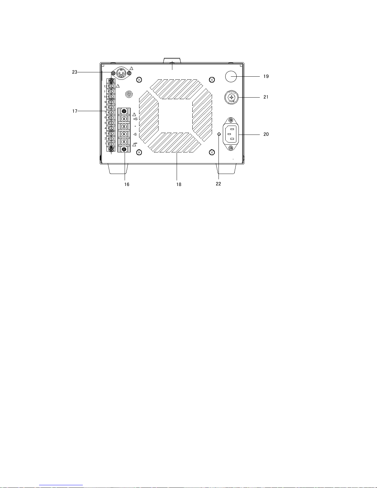
5-2. REAR PANEL
Fig. 4
16 Output terminal
(+) output terminals and (±) sensor terminals.
17 Control terminals
Terminals for remote control and series/parallel operation.
18 Fan
Forced air cooled fan. Keep it apart from walls more than 30 cm.
19 Cap
Cap of the fuse holder.
20 AC input terminals
Input terminals of power supply. Connect the AC cord provided.
21 Fuse holder
(A model having 20 A or 30 A output rating is not fitted with a fuse holder.
It has a blind cap, instead of the fuse holder.)
Input fuse holder of power supply.
22 Hole for mounting the retainer of power input connector.
23 External control terminal (Output ON/OFF terminal)
Input external contact signals for turning on and off the output of this product into this
terminal.
----

12
6. OPERATION
6-1. As a Constant-Voltage Power Supply
1) Check the rated input voltage, then connect the power cord.
2) Turn the voltage adjuster knob (VOLTAGE) fully counter-clockwise.
3) Turn on the power switch. The POWER (red) indicator light and the device is operated.
Make sure the OUTPUT switch is off (the indicator is out).
4) Set a desired voltage with the voltage adjuster knob (VOLTAGE). No voltage develops at
the output terminals still.
5) Set a current limit.
Keeping the V/I CHECK switch depressed, set a desired limit of output current with the
current adjuster knob (CURRENT).
6) Turn on output
Turn on the OUTPUT switch, and the preset voltage is output at the output terminals
with the output indicator lit.
Note 1 : If excessive current flows as when the load is shorted, the device performs
constant-current operation at the preset limit of output current and the output
voltage falls.
Note 2 : If the overvoltage protection level is set lower than the preset level of output
voltage, the power switch will be turned off by overvoltage protection.
See how to set overvoltage protection.
6-2. As a Constant-Current Power Supply
1) Check the rated input voltage, then connect the power cord.
2) Turn the current adjuster knob (CURRENT) fully counter-clockwise.
3) Turn on the power switch. The POWER (red) indicator lights and the device is in
constant-current mode. Make sure that the OUTPUT switch is off (the indicator is out)
4) Set a desired current.
Keeping the V/I CHECK switch depressed, set a desired constant current with the
current adjuster knob (CURRENT).
5) Set a voltage limit.
Set a desired voltage limit with the voltage adjuster knob (VOLTAGE). It is the
overvoltage protection level.

13
6) Turn on output.
Turn on the OUTPUT switch, and the output indicator lights and the power is output
through the output terminals.
Note : If it is not preferable to apply current suddenly like to a large inductance load, turn
the current adjuster knob (CURRENT) fully counterclockwise and increase current
gradually after turning on the output.
6-3. How to Check Voltage and Current
1) Voltage/Current presetting
When the V/I CHECK switch is depressed, the constant-voltage is indicated on the
voltmeter and constant current is indicated on the current meter.
Hereupon, it is possible to set a desired voltage or current with the voltage adjuster
knob (VOLTAGE) or current adjuster knob (CURRENT).
2) Voltage/Current check
When the V/I CHECK switch is depressed at constant-current operation, the preset
current and the preset voltage can be checked.
6-4. How to Set Overvoltage Protection (OVP) Level
Keeping the OVP CHECK switch depressed, the overvoltage protection level indicated on
the voltmeter.
1) Turn off the OUTPUT switch.
2) Keeping the OVP CHECK switch depressed, screw the OVP adjuster with a screwdriver
and set an overvoltage protection level.
3) Turn on the OUTPUT switch with no load connected (the indicator lights). Raising the
output voltage gradually, check if the power switch turns off at the preset overvoltage
protection level.
4) Set the overvoltage protection level at the maximum reading or the output voltmeter if
overvoltage protection is not necessary.

14
7. APPLICATION
7-1. Use of Rear-Panel Terminals
Rear-panel output control
Fig. 5
The output and control terminals shown above are equipped on the rear panel. These
terminals may be used to perform remote sensing, remote control of output voltage and
output current, master/slave control operation with power supply connected in series or
paralled.
7-2. Remote Sensing
When the device is connected to a load, voltage drops due to contact resistance at the
output terminals and resistance of conductors. Remote sensing is performed to
compensate for the voltage drop.
1) Turn off power.
2) Remote the short bars(+)-(+S) and (-)-(-S).
3) Connect (+S) and (-S) to the load. Use a two-core shield cable for these sensing lines
and connect the shield line to (+) output.
4) (+) and (-) may be taken out from the output terminals on the panel or directly connected
to the load from the (+) and (-) terminals of the rear panel. Voltage drop of up to 1.2V per
way of the output line may be compensated for. If the voltage drop is lager than 0.5V, the
maximum rated voltage drops accordingly.
--S +
+S
①②③④⑤⑥⑦⑧⑨⑩⑪⑫
Control terminals
15
Fig. 6
Note : If the load is remote, oscillation might happen due to inductance and capacitance of
the output line. In such a case, connect an electrolytic capacitor of some 100μF in
parallel with the load as shown above.
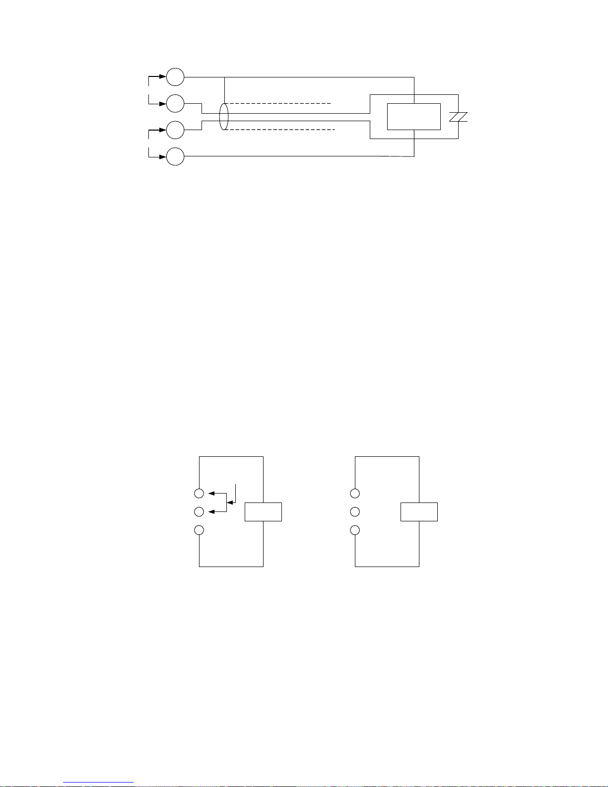
7-3. Remote Control of Constant-voltage (Resistance, voltage)
---------- Precautions When Using Remote Control -----------
This unit adopts the floating circuit system. It has terminals isolated from the frame and
controls output power on the basis of the positive (+) output terminal.
To control the constant voltage and constant current settings using external voltage,
connect the positive (+) output terminal and GND terminal on the front panel as follows.
The GND and positive (+) terminals should be connected with the short bar (as shown
above) or open (as shown below) :
Note : In case of output voltage or current control by external voltage, the negative side of
the external voltage line is connected to the (+S) terminal (GND level of the analog
control circuit inside of the unit) side.
Use floated external voltage circuit from any conductive materials against output
potential of the main unit in a floating condition to prevent accidents or
malfunctioning. In case of using plural number of power supplies with external
+
+S
-
-S
Load
Two core shield
+
(Note)
×
×
GND
+
-
Load
Short bar
+
-
Load
GND
16
controllers, each unit should be floated independently.
7-3-1. Control by resistance (Ⅰ)
It is possible to output voltage which is proportional to resistance.
1) Turn off power.
2) Remove the short bar ①-②.
3) Connect variable resistor R
1 (10k ohms) across 1 and 3 as shown Fig. 7.
Note : R
1 must be 10k ohms. Use a two-core shield cable and connect the shield line to
⑤. For R1 select one which will be affected little by temperature changes, aging
effects, and noises.
Fig. 7
Output voltage
(R1≦10kΩ)
V0 [ V ] : Output voltage
V
max [ V ] : Maximum rated output voltage
R
1 [ kΩ] : External resistance
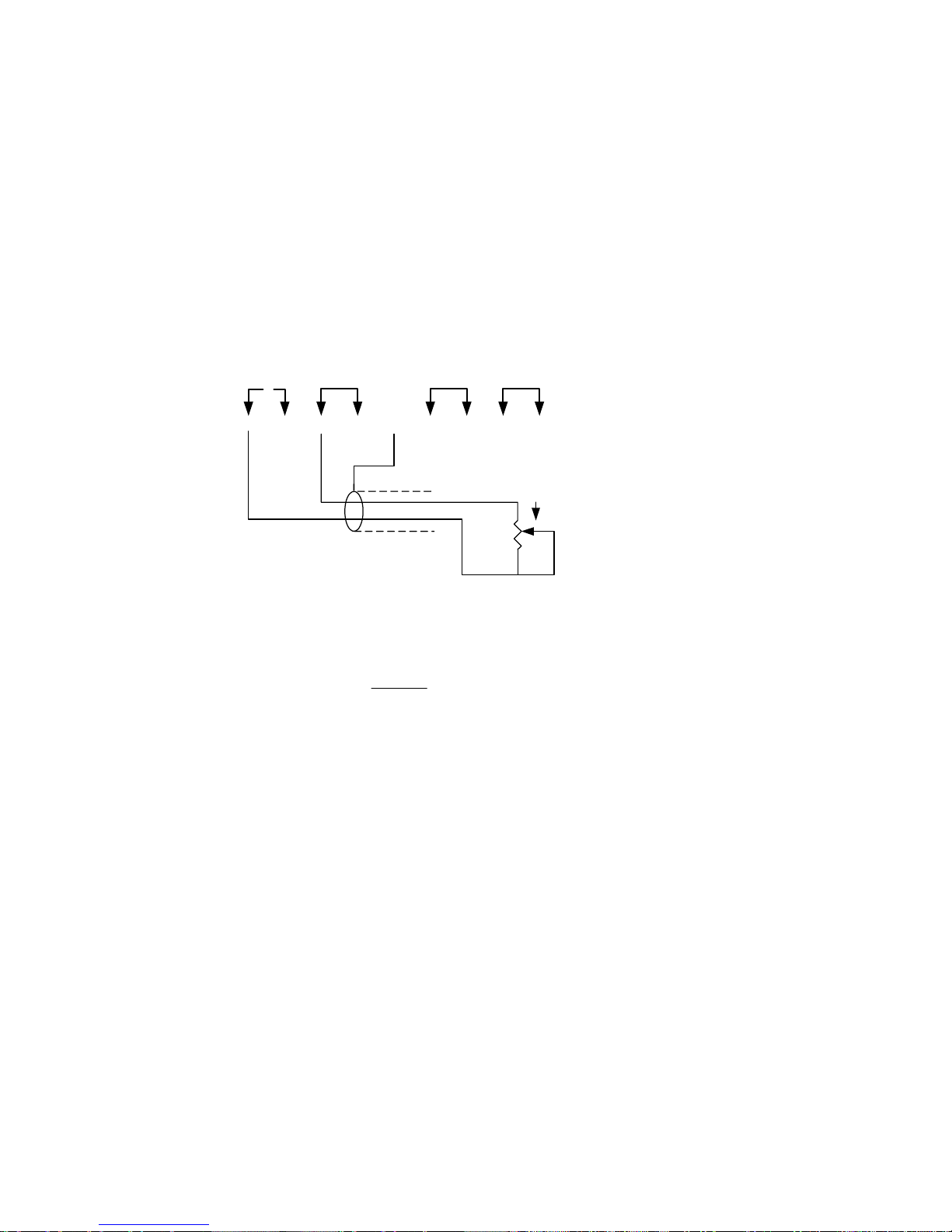
7-3-2. Control by resistance (Ⅱ)
It is possible to output voltage which is inversely proportional to resistance. Overshoot
does not occur when switching resistance.
1) Turn off power.
2) Remove the short bar ③-④ and connect variable resistor R
2 across ③ and ④ as
shown Fig. 8. Use a two-core shield cable and connect the shield line to ⑤.
①②③④⑤⑥⑦⑧⑨⑩⑪⑫
R1=10kΩ
Two-core shield
×
V
0
Vmax
10
×
R
1
[V]
≒
17
Fig. 8
Output voltage
Vref : Reference voltage (approx. 0 to 10V)
Set with the voltage control of the panel.
R
2 : 0≦R2≦∞
Rs, Rf : Constants depending on model.
Rated output voltage
R
s (kΩ) Rf (kΩ)
18 V
10kΩ 18kΩ
36 V
10kΩ 36kΩ
56 V
10kΩ 56kΩ
110 V
10kΩ 110kΩ
Note 1 : The output voltage is determined with R
2 and Rref as given above. The output
voltage is 0V if R
2 is infinite (open). Set Vref with the voltage control provided
on the panel. To fix it or set it externally, connect a 10k ohm resistor which has a
good temperature characteristic across ① and ③ according to “Control by
resistance (Ⅰ)”. The voltage control of the panel is now ineffective.
Note 2 : Be sure to adjust the output voltage at OUTPUT ON mode. In OUTPUT OFF or
V/I CHECK mode, there is a slight error in meter reading.
①②③④⑤⑥⑦⑧⑨⑩⑪⑫
R2
Two-core shield
×
V
0
R
×
[V]
2
V
ref
+
R
≒
R
s
f

18
7-3-3. Control by external voltage
It is possible to output voltage which is proportional to voltage.
1) Turn off power.
2) Remove the short bar ③-④ and connect external voltage V
1 across ④ and ⑤ as
shown Fig. 9. Be very careful about the polarity.
Fig. 9
Note : The external signal voltage should be 0 to 10V. The input impedance across ④
and ⑤ is approximately 10k ohms. Use a two-core shield cable and connect the
shield line to ⑤.
(0≦V1≦10V)
V
0 [V] : Output voltage
V
1 [V] : External signal voltage
V
max [V] : Maximum rated output voltage
7-4. Remote Control of Constant Current (Resistance, Voltage)
Refer to the “PRECAUTIONS WHEN USING REMOTE CONTROL” under “REMOTE
CONTROL OF CONSTANT-VOLTAGE”
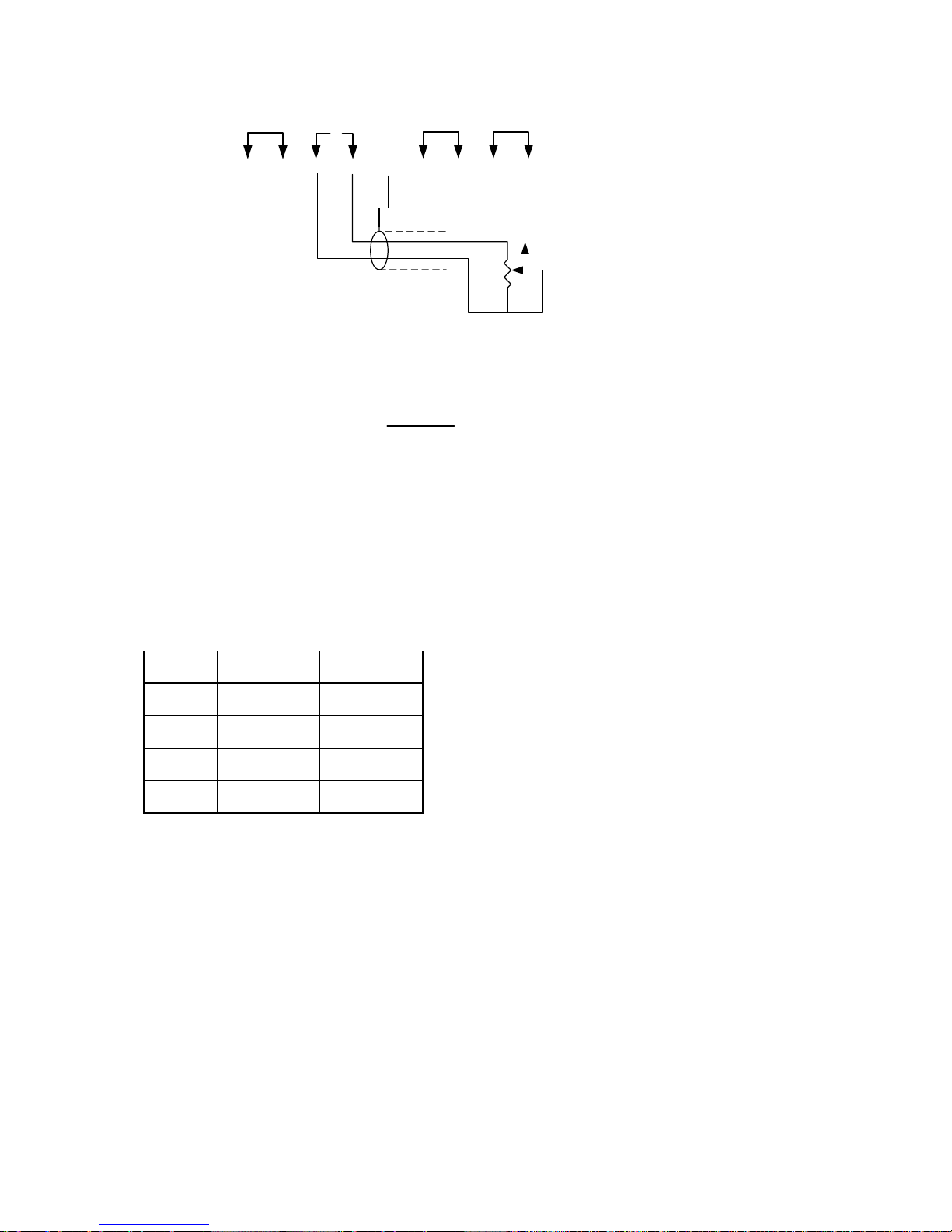
7-4-1. Control by resistance
Control of constant-current is possible in proportion with resistance.
1) Turn off power.
2) Remove the short bar ⑥-⑦.
3) Connect variable resistor R
3 (10k ohms) across ⑥ and ⑧ as shown Fig. 10.
①②③④⑤⑥⑦⑧⑨⑩⑪⑫
Two-core shield
×
V1
+
V
≒
0
Vmax
10
×
V
1
[V]

19
Fig. 10
Output current
(R
3≦10kΩ)
I0 [A] : Output current
I
max [A] : Maximum rated current
R3 [kΩ] : External resistance
Note : R
3 must be 10k ohms or less (R3 ≦ 10kΩ). Use a two-core shield cable and
connect the shield line to ⑪.
7-4-2. Control by external voltage
It is possible to control constant current in proportion to voltage.
1) Turn off power.
2) Remove the short bar ⑧-⑨ and connect external voltage V2 across ⑨ and ⑪ as
shown Fig. 11. Be very careful about the polarity.
Fig. 11
R3
①②③④⑤⑥
⑦
⑧
⑨
⑩⑪⑫
Two-core shield
×
①②③④⑤⑥
⑦
⑧
⑨
⑩⑪
⑫
Two-core shield
×
V
+
2
I
0
Imax
10
×
R
3
[A]
≒

20
(0≦V2≦10V)
I
0 [A] : Output current
I
max [A] : Maximum rated current
V
2 [V] : External signal voltage
Note : The external signal voltage should be 0 to 10V. The input impedance across ⑨
and
⑪ is approximately 10k ohms. Use a two-core shield cable and connect the
shield line to
⑪.
7-5. Series/Parallel Connection Operation
With some units connected in series or in parallel, it is possible to control all units with one
unit taken as the master and the other as slaves.
7-5-1. Series connection
T
he output voltage is the sum of the output voltages of the units. The output voltage and
current of each slave unit are controllable with the constant-voltage and constant-current
controls of the master unit.
1) Turn off power.
2) Remove the short bar
③-④ of each slave unit.
3) Connect external resistor R as shown Fig. 12.
4) Ground the GND terminal either of the master unit if the positive line is grounded or of
the last slave unit if the negative line is grounded. (The output connection diagram shown
the negative line grounded.)

21
Connect of control terminals
Fig. 12
Output connection
Fig. 13
*Set the current controls of all slave units at maximum position.
①②③④⑤⑥⑦⑧⑨⑩⑪⑫
①②③④⑤⑥⑦⑧⑨⑩⑪⑫
①②③④⑤⑥⑦⑧⑨⑩⑪⑫
R1
R2
×
×
Master
Slave
Slave
CC
CV
POWER
CURRENT VOLTAGE
V/I CHECK
OVP CHECK
OUTPUT
ON
OFF
+
-
OFF
CC
CV
POWER
CURRENT VOLTAGE
V/I CHECK
OVP CHECK
OUTPUT
ON
OFF
+
-
OFF
CC
CV
POWER
CURRENT VOLTAGE
V/I CHECK
OVP CHECK
OUTPUT
ON
OFF
+
-
OFF
E1
E2
E3
GND
Load
+
-
At negative ground
Master
Slave(1)
Slave(2)
At positive ground
E
0=E1+E2+E3

22
7-5-2. How to determine external resistance R1 and R2.
E1 [V] : Output voltage of master
E
2 [V] : Output voltage of slave ① when master’s output voltage is E1
Rs, Rf : Slave ①’s constants depending on model.
Rated output voltage
R
s (kΩ) Rf (kΩ)
18 V
10k
Ω 18kΩ
36 V
10k
Ω 36kΩ
56 V
10k
Ω 56kΩ
110 V
10k
Ω 110kΩ
To obtain R
2, replace E1 and E2 with E3 in the above equation.
Now, master unit controls slave unit 1 and slave unit 1 controls slave unit 2.
Maximum voltage during series operation does not exceed rating of the withstand voltage
to ground. Be careful about the power ratings of R
1 and R2 and use ones having a good
temperature characteristic.
For remote sensing during series operation, use the (+S) terminal of the master with the
(+) sensor or the (-S) terminal of the last slave with the (-) sensor (refer to the section of
remote sensing).
7-5-3. Parallel connection
The output current is the sum of the output currents of the units. The output voltage and
current of each slave unit are controllable with the constant-voltage and constant-current
controls of the master unit.
1) Turn off power.
2) Remove the short bar
⑧-⑨ of each slave unit.
3) Connect the master and slave units as shown Fig. 15.

23
4) Make connection between each unit and load with a cable of the same length.
5) Ground the GND terminal of the master unit’s panel. (The output connection diagram
shows the negative line grounded.)
Connect of control terminal
Fig. 14
Output connection
Fig. 15
* Set the voltage controls of all slave units at maximum position.
The master unit performs constant-voltage operation (CV) and the slave units
constant-current operation (CC).
For remote sensing during parallel operation, make connection from the (+S) and (-S)
terminals of the master (refer to the section of remote sensing).
With the rated output voltage is less than 10V, this connection is not possible.
①②③④⑤⑥⑦⑧⑨⑩⑪⑫
①②③④⑤⑥⑦⑧⑨⑩⑪⑫
①②③④⑤⑥⑦⑧⑨⑩⑪⑫
×
×
Master
Slave
Slave
CC
CV
POWER
CURRENT VOLTAGE
V/I CHECK
OVP CHECK
OUTPUT
ON
OFF
+
-
OFF
CC
CV
POWER
CURRENT VOLTAGE
V/I CHECK
OVP CHECK
OUTPUT
ON
OFF
+
-
OFF
CC
CV
POWER
CURRENT VOLTAGE
V/I CHECK
OVP CHECK
OUTPUT
ON
OFF
+
-
OFF
Slave(2)
Slave(1)
Master
GND
I
1
I2
I3
Load
+
-
I
0=I1+I2+I3

24
Note : For connection of the parallel operation with different models, consult agent and
our distributor.
7-6. Constant-Current Charging/Discharging of Battery
7-6-1. Constant-current charging
It is possible to charge a battery or capacitor automatically with a charging current or a final
voltage preset.
1) Keeping the V/I CHECK switch depressed, set the final charging voltage with the
constant-voltage control and the charging current with the constant-current control.
2) Close switch S1, and constant-current charging starts and continues until the final
voltage is reached.
Output switch
Fig. 16
Note 1 : Be sure to equalize the polarity of the supply power and battery.
Note 2 : Current would flow back into the power source if the supply voltage is lower
than the battery voltage, the OUTPUT switch is off, or power supply is turned
off. In this case reconnect diode D
1 in the forward direction.
7-7. Turning On and Off the Output Using External Contact Signals
1) Set the OUTPUT selector switch on the front panel to OFF.
Short-circuit the DIN connector pins 1 and 4 in the upper left of the rear panel.
2) Set the OUTPUT switch to ON. The output of this product is turned off.
3) In the condition established in 2) above, open the DIN connector pins 1 and 4. The
Power
Supply
+
-
S1
D
1
Battely
Capacitor
+
+
+
-
-

25
output of this product is turned on.
Note 1 : The DIN connector pins are electrically connected to the positive output terminal.
Thus, be sure to use them in the float condition.
Note 2 : A 7-pin connector cable for connecting the GP-IB adapter <GP-600B> cannot be
connected to the 5-pin connector shown above. To turn on add off the output or
make interruptions in the CV/CC mode or power off mode, the external I/O unit
<OP-18-PD> need be installed.
(The OP-18-PD is a factory option, since the PD-A power supply unit need be
remade internally to install the OP-18-PD.)
Note 3 : If the external I/O unit <OP-18-PD> is installed on the PD-A power supply unit, the
above-shown connector is changed into the 7-pin DIN connector exclusive for
the <GP-600B>. Thus, the output cannot be turned on or off using the external
contact signals.
3
5142

26
8. OPTIONAL ACCESSORIES
1) Rack mount adapter----------------------------- RK-601
2) GP-IB adapter ------------------------------------ GP-600B
9. MAINTENANCE
Replacing Fuse
The PD-A power supply unit will not run if the fuse blows out.
Some models are supplied with spare fuses, in addition to the fuses built in the units.
(Models of rated outputs below 10A)
The PD-A power supply unit employs a special fuse filled with anti-arc agent (quartz sand).
If the spare fuses also blows out, do not try to replace it by yourself. Please contact your
dealer or our distributor.
A model of 20A or more rating is not supplied with a spare fuse. The built-in fuse cannot be
replaced without opening the case. Trial to replace the fuse by yourself may result in
electrocution or fire. If the fuse should be replaced, be sure to contact your dealer or our
distributor.

27
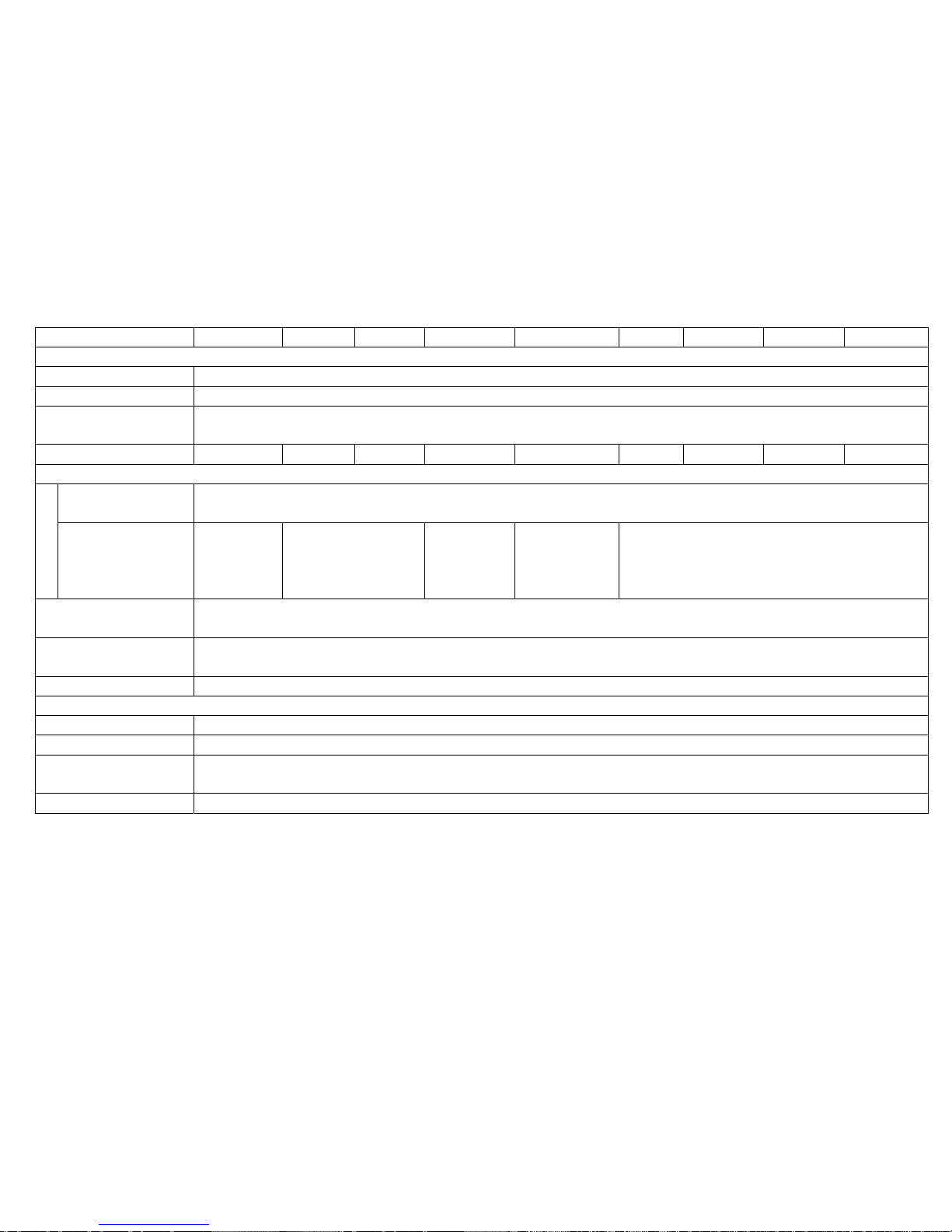
10. TROUBLESHOOTING
Check as noted below if there is anything wrong.
If the trouble cannot be correct, call the dealer.
Sympton Check Cause
Power switch does
not turn on.
*Power lamp not lit.
*Short bar coming off.
*Overvoltage protection
worked.
*Power cord disconnected or
connected defectively.
*Input switch defective.
*Input fuse blown.
*Rear-panel short bar
disconnected or loose.
*Voltage set too low.
Output voltage is zero
or low.
*Short bar coming off.
*Constant-voltage/current
Lamps do not switch.
*Ammeter deflects with
output off.
*Oscillating
*Short bar installed defectively.
*Circuit defective.
*Output diode broken.
*Oscillation by remote sensing.
Output is excessive.
*Short bar coming off.
*Output voltage/current
do not fall.
*Short bars 1 – 2 and 6 – 7 come
off.
* Power transistor or control
circuit defective.
Output is not steady.
*Short bar coming off.
*Input voltage wrong.
*Oscillating
*Sensing terminal
floating.
*Strong magnetic/electric
fields near-by.
*Other
*Short bar installed defectively.
*Out of the rated input voltage
range.
*Oscillation by special load.
* Proper connection of sensing
terminal.
* Keep away from oscillation
sources.
28
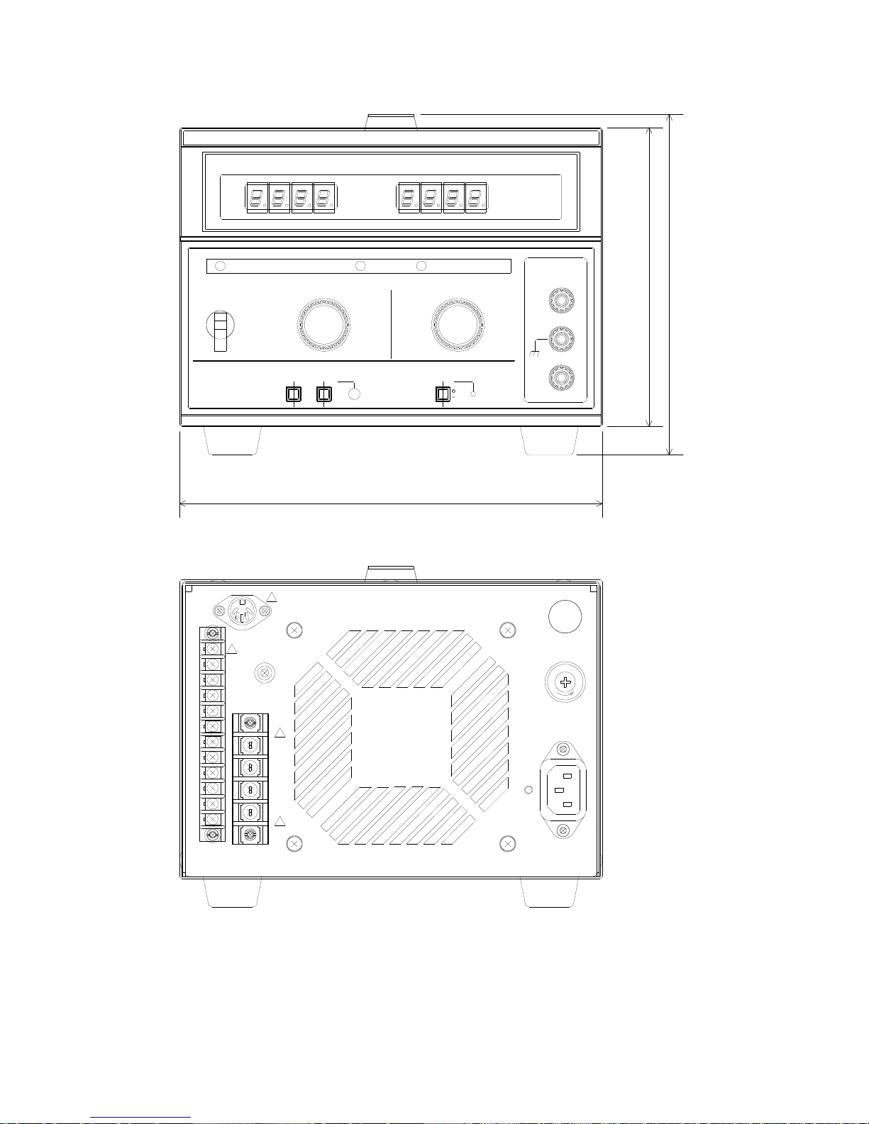
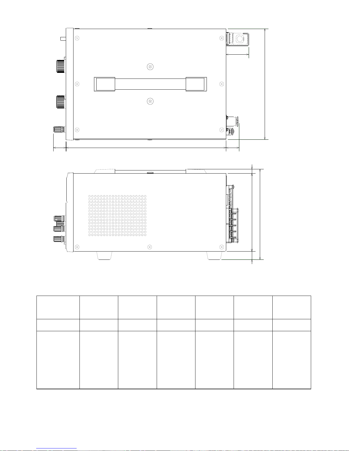
11. DIMENSIONS
Fig. 17
CC CV
POWER CURRENT VOLTAGE
V/I CHECK OVP CHECK
OUTPUT
ON
OFF
+
-
OFF
A
V
!
!
!
!
-
2
1
3
4
-
5
6
7
-
8
9
-
10
11
12
+S
+
-
-S
E
S
F
U
208
147
168MAX
29
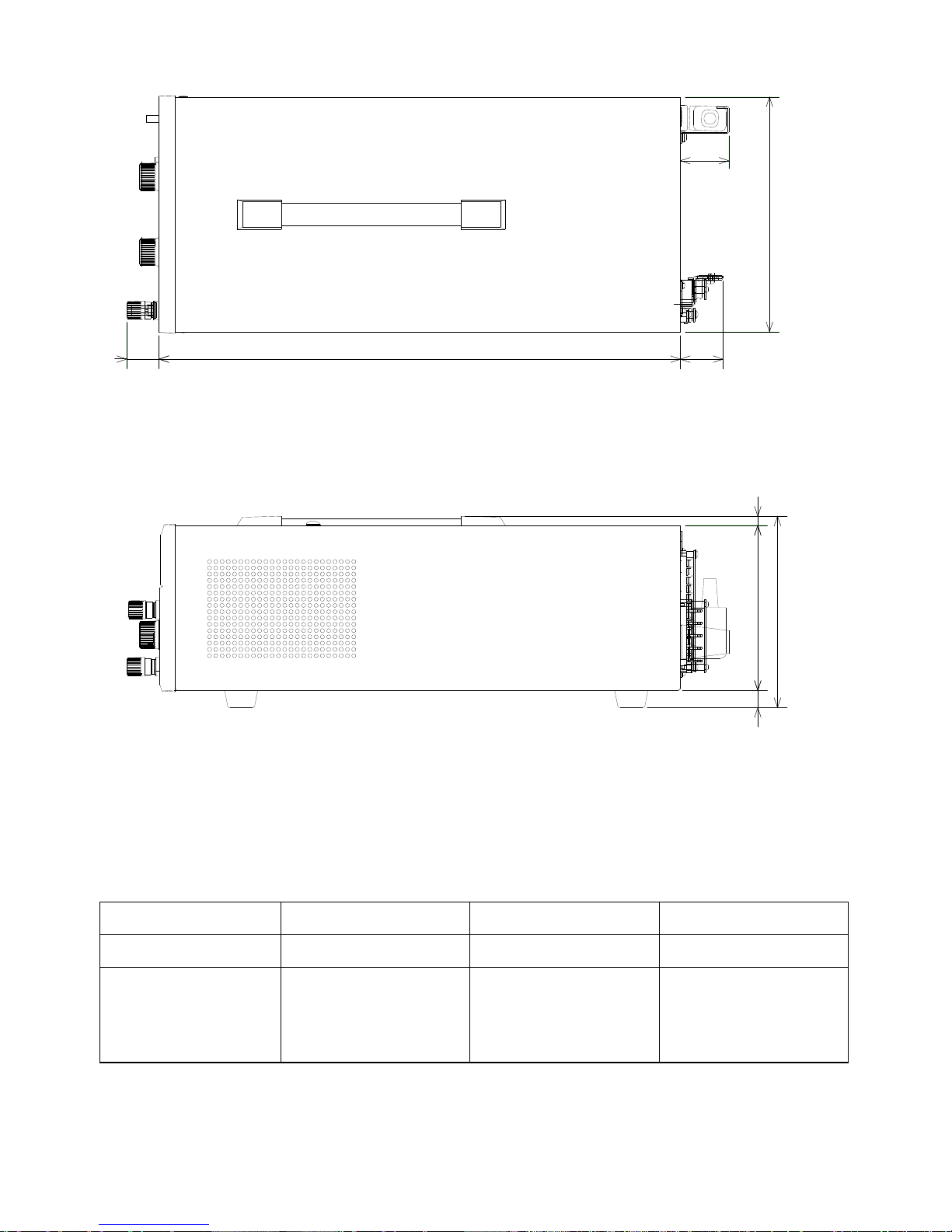
Fig. 18
Model PD18-20AD PD18-30AD PD36-20AD
L 420 457 420
L1(mm)
(including power
input connecter)
38 38 38
35
208
28
15
145
8
168
L
L1
30
Fig. 19
Model
PD18
-10AD
PD36
-10AD
PD56
-6AD
PD56
-10AD
PD110
-3AD
PD110
-5AD
L 300 300 300 348 300 348
L1(mm)
(including
power
input
connecter)
32 38 38 38 38 38
14515
168
23 23
208
8
L1
L

7F Towa Fudosan Shin Yokohama Bldg.
2-18-13, Shin Yokohama, Kohoku-ku,Yokohama, Kanagawa, 222-0033 Japan
http://www.texio.co.jp/
 Loading...