


©PRINTED IN JAPAN B71-0116-10
INSTRUCTION MANUAL
REGULATED DC POWER SUPPLY
PA-B SERIES
PA10-5B PA18-1.2B PA18-2B
PA18-3B PA18-5B PA36-1.2B
PA36-2B PA36-3B PA80-1B
PA120-0.6B PA160-0.4B PA250-0.25B
PA250-0.42B PA350-0.2B PA600-0.1B

CONTENTS
USING THE PRODUCT SAFELY ..................................................Ⅰ-Ⅴ
1.OUTLINE AND FEATURES_________________________________1
2.SPECIFICATIONS ________________________________________2
3. INSTRUCTIONS ON USE _________________________________ 10
3-1. Checking Source Voltage...........................................................................10
3-2. Connection of Power Cable.......................................................................10
3-3. Precautions for Connecting Output Terminals.........................................10
3-4.Switches on Front Panel and Connection Terminals on Rear Panel....11
3-5.Digital Display .............................................................................................11
3-6. Switching Points of Relay...........................................................................11
3-7. Installation Environments ...........................................................................12
3-8. Rack Mounting ............................................................................................13
3-9. Options.........................................................................................................14
4.PANEL EXPLANATION ___________________________________15
4-1. Front panel...................................................................................................16
4-2.Rear panel...................................................................................................19
5. OPERATION PROCEDURES ______________________________21
5-1.Independent Operation..............................................................................21
5-2.Remote Sensing.........................................................................................21
5-3.OVP..............................................................................................................22
5-4.Remote Control Functions.........................................................................23

5-5.Output ON/OFF Remote Control..............................................................25
5-6.Constant-Voltage Remote Control............................................................26
5-7.Constant-Current Remote Control............................................................29
5-8.Status Signals .............................................................................................32
5-9. Monitoring Voltage and Current.................................................................33
5-10.Series and Parallel Connections ............................................................34
5-11.One-Control Parallel Operation...............................................................36
5-12.Recharging Battery.................................................................................38
6. TROUBLES AND PHENOMENA ____________________________39
7.EXTERNAL DIMENSIONS FIGURE _________________________40
This instruction manual applies to fifteen models: PA10-5B, PA18-1.2B,
PA18-2B, PA18-3B, PA18-5B, PA36-1.2B, PA36-2B, PA36-3B,
PA80-1B, PA120-0.6B, PA160-0.4B, PA250-0.25B, PA250-0.42B,
PA350-0.2B, and PA600-0.1B. The operation procedures, etc.
described in this manual are common to all models, except some
difference in the specifications. Please refer to the descriptions about
the purchased model.
I
USING THE PRODUCT SAFELY
■ Preface
To use the product safely, read this manual to the end. Before
using this product, understand how to correctly use it.
If you read this manual but you do not understand how to use it,
call the company that is indicated on the back cover of this
manual. After you read this manual, keep it so that you can read
it anytime as required.
■ Notes on reading this manual
The contents of this manual include technical terms in part of their
explanation.
If you do not understand those terms, do not hesitate to ask the
company or each distributor.
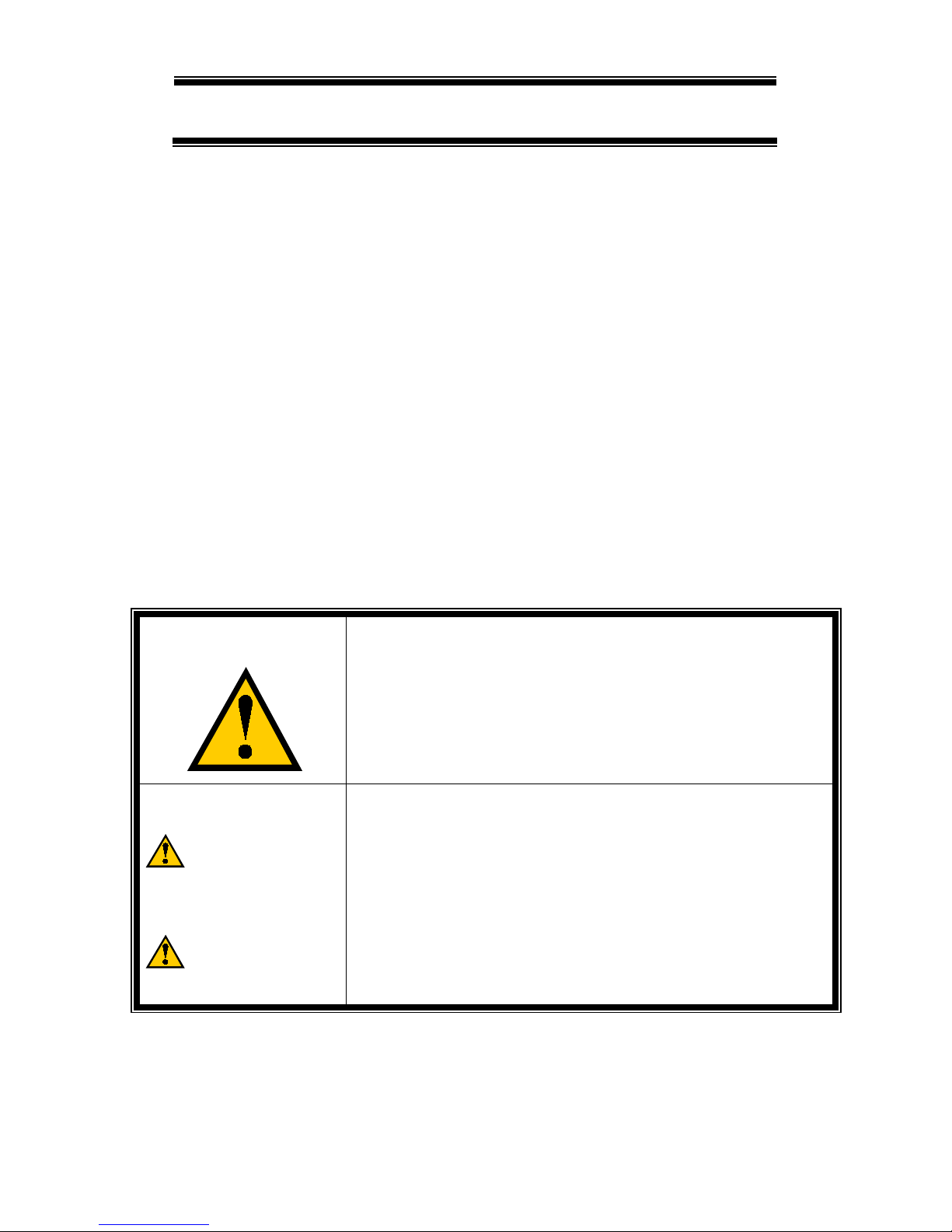
■ Pictorial indication and warning character indication
This manual and product show the warning and caution items
required to safely use the product. The following pictorial
indication and warning character indication are provided.
<Pictorial Indication>
Some part of this product or the manual
may show
this pictorial indication. In this case, if the product
is incorrectly used in that part, a serious danger may
be brought about on the user's body or the product.
To use the part with this pictorial indication, be sure
to refer to this manual.
<Warning character
Indication>
WARNING
CAUTION
If you use the product, ignoring this indication, you
may get killed or seriously injured. This indication
shows that the warning item to avoid the danger is
provided.
If you incorrectly use the prod
uct, ignoring this
indication, you may get slightly injured or the product
may be damaged. This indication shows that the
caution item to avoid the danger is provided.
Please acknowledge beforehand that our company does not assume
the responsibility at all except when the liability for damage in the law
is admitted for the user or the third person’s misuse, abuse, neglect,
unauthorized product modification or failure to follow this manual, and
other troubles, or any damages caused by use of this product.

II
USING THE PRODUCT SAFELY
WARNING
■ Do not remove the product's covers and panels
Never remove the product's covers and panels for any purpose.
Otherwise, electric shock to the users or a fire may be incurred.
■ Warning on using the product
The warning items given below are to avoid danger to the user's
body and life and avoid the damage and deterioration of the product.
Use the product, observing the following warning and caution items.
■ Warning item on installation environment
●Operating temperature
Use the product within the operating temperature indicated in
the rating column. If the product is used with the vents of the
product blocked or in high ambient temperatures, a fire may occur.
●Operating humidity
Use the product within the operating humidity indicated in the
rating column. Watch out for condensation by a sharp humidity
change such as transfer to a room with a different humidity.
Also, do not operate the product with wet hands. Otherwise, an
electric shock or fire may occur.
●Use in a gas
Use in and around a place where an inflammable or explosive
gas or steam is generated or stored may result in an explosion
and fire. Do not operate the product in such an environment.
Also, use in and around a place where a corrosive gas is
generated or spreading causes a serious damage to the product.
Do not use the product in such an environment.
●Do not let foreign matter in
Do not insert metal and flammable materials into the product
from its vent and spill water on it. Otherwise, an electric shock
and fire may occur.

III
USING THE PRODUCT SAFELY
WARNING
■ Warning about Power Source
●Input Power
Check the source voltage before using the PA-B series. The
product has an input voltage selector switch above the AC inlet
on the rear panel. The figure below shows the source voltage
of the PA-B series. Note that using the PA-B series on different
voltage may result in a trouble or breakdown. Check the switch,
and connect the power cable to the AC outlet.
●Power Cable
IMPORTANT: The power cable set supplied with the PA-B series
is unusable for any other product.
Using a power cable not supplied with the PA-B series may result
in electric shocks, electrocution or a fire. If the power cable set
supplied with the PA-B series is damaged, stop using the PA-B
series and contact our distributor. Using the PA-B series with
the damaged power cable may result in electric shocks,
electrocution or a fire. The power cable set supplied with the
PA-B series is to be used for 220 VAC power. Contact the
distributor if you intend to use the PA-B series on input voltage
other than 220 VAC.
●The fuse for protection
The product doesn't operate when the fuse for input protection is
blown. Users can replace the fuse by themselves according to
some instructions including cautions and remarks on the user’s
manual. It is important to be very careful to keep the instructions
strictly without fail. Misplacing may cause danger of fire.
220
V

IV
USING THE PRODUCT SAFELY
WARNING
■ Warning item on grounding
The product has the GND terminal on the panel surface to protect
the user from electric shock and protect the product. Be sure to
ground the product to safely use it.
■ Warning item on abnormality while in use
If smoke or fire is generated from the product while in use, stop using
the product, turn off the switch, and remove the power cord plug
from the outlet. After confirming that no other devices catch fire,
call the company or our distributor.
CAUTION
■ Connection of Remote Control Input and Output Terminals
*The maximum input rating of the remote control input and
output terminals is determined in order to avoid damages to the
product. Do not input or output voltage/current exceeding the
rating described in the instruction manual. Excessive input or
output may cause a trouble or breakdown of the product.
*When the voltage or current is controlled according to external
voltage, the negative (-) side of the external voltage unit is
connected with the -S output terminal of the PA-B series. Use
the output circuit of the external voltage unit in the condition
where it is floated from the frame in order to avoid accidents or
malfunctioning.
When several power supply units are used for a remote control
application, each external power supply unit must be floated.
*The negative (-) side of the voltage/current monitor terminal is
internally connected with the -S terminal. Use the input circuit
of the external measuring instrument in the condition where it is
floated from the frame in order to avoid accidents or
malfunctioning.

V
USING THE PRODUCT SAFELY
CAUTION
■ Input/output terminal
Maximum input to the input terminals is specified to prevent the
product from being damaged.
Do not supply input, exceeding the specifications that are
indicated in the "Rating" or "Caution on use" column in this
manual of the product. Otherwise, a product failure is caused.
Also, do not supply power to the output terminals from the
outside. Otherwise, a product failure is caused.
■ When the product is left unused for a long time
Be sure to remove the power plug from the outlet.
<Calibration>
Although the performance and specifications of the product are
checked under strict quality control during shipment from the
factory, they may slightly change because of secular changes in
its parts. It is recommended to periodically calibrate the product
so that it is used with its performance and specifications stable.
For consultation about the product calibration, call the distributor
or the company where you bought the product.
<Daily maintenance>
When you clean off the dirt of the product covers, panels, and
knobs, avoid solvents such as thinner and benzene. Otherwise,
paint may peel off or the resin surface may be affected.
To wipe off the covers, panels, and knobs, use a soft cloth with
neutral detergent in it.
During cleaning, be careful that water, detergents, and other
foreign matters do not get into the product.
If a liquid or metal gets into the product, an electric shock and fire
are caused. During cleaning, remove the power cord plug from
the outlet.
Use the product correctly and safely, observing the above warning
and caution items.
Because this manual indicates caution items even in individual
items, observe those caution items to correctly use the product.
If you have questions or comments about the content of this manual,
call the distributor or the company.

1
1.OUTLINE AND FEATURES
The PA-B series is a high-performance DC constant-voltage, constantcurrent power supply unit with 3 1/2-digit voltage indicator LEDs
and 3-digit current indicator LEDs. The series regulator control
allows the user to vary the output from 0 to the rated output. The
output controller, a 10-turn winding type variable resistor, offers fine
control of output voltage and current. It is possible to set the
output voltage and current even when the output is off. The output
voltage and current may be checked on digital indicators simultaneously.
The PA-B series are high-cost-performance power supply units with
output On/Off, output sensing and various remote control functions
and fully meet various users' needs. They have a wide variety of
applications such as power supplies for researches and
development, power supplies for aging, and fixed power supplies
for many systems according to purposes.
- Low-Ripple and Low-Noise Power Supply Unit
The series regulator control system eliminates ripples and noises
to quite low levels and provides low temperature coefficient and
superior electrical performances.
- Simultaneous Voltage and Current Digital Display LEDs
3 1/2-digit automatic-range voltage indicator LEDs (fixed range
indicators on the PA18-1.2B, PA18-2B, PA18-3B, PA18-5B,
PA120-0.6B and PA160-0.4B) and 3-digit current indicator LEDs
enable simultaneous check and setting of the voltage and current.
The LEDs give indications in green in the constant-voltage mode
and in red in the constant-current mode.
- Increased Output in Series/Parallel Operation
Series connection increases the output voltage (except the
PA350-0.2B, and PA600-0.1B). Parallel connection increases the
output current. One-control parallel connection allows control of
several slave power supply units from a single master power supply unit.
- With Floating Output/Voltage Remote Sensing Terminal
The output terminal is a floating type terminal and may be used in
the positive or negative polarity. A voltage remote sensing
terminal is provided on the front panel for fine control of the load
terminal voltage (except the PA80-1B, PA120-0.6B, PA160-0.4B,
PA250-0.25B, PA250-0.42B, PA350-0.2B and PA600-0.1B).
- Various Remote Control Terminals for Systematization
The PA-B series have various remote control terminals, which
allow the output to be turned on or off or fixed using external
contact signals and the output voltage or current to be
remote-controlled according to external voltage (0 to 10 V) or input
resistance (0 Ω to 10 kΩ).

2
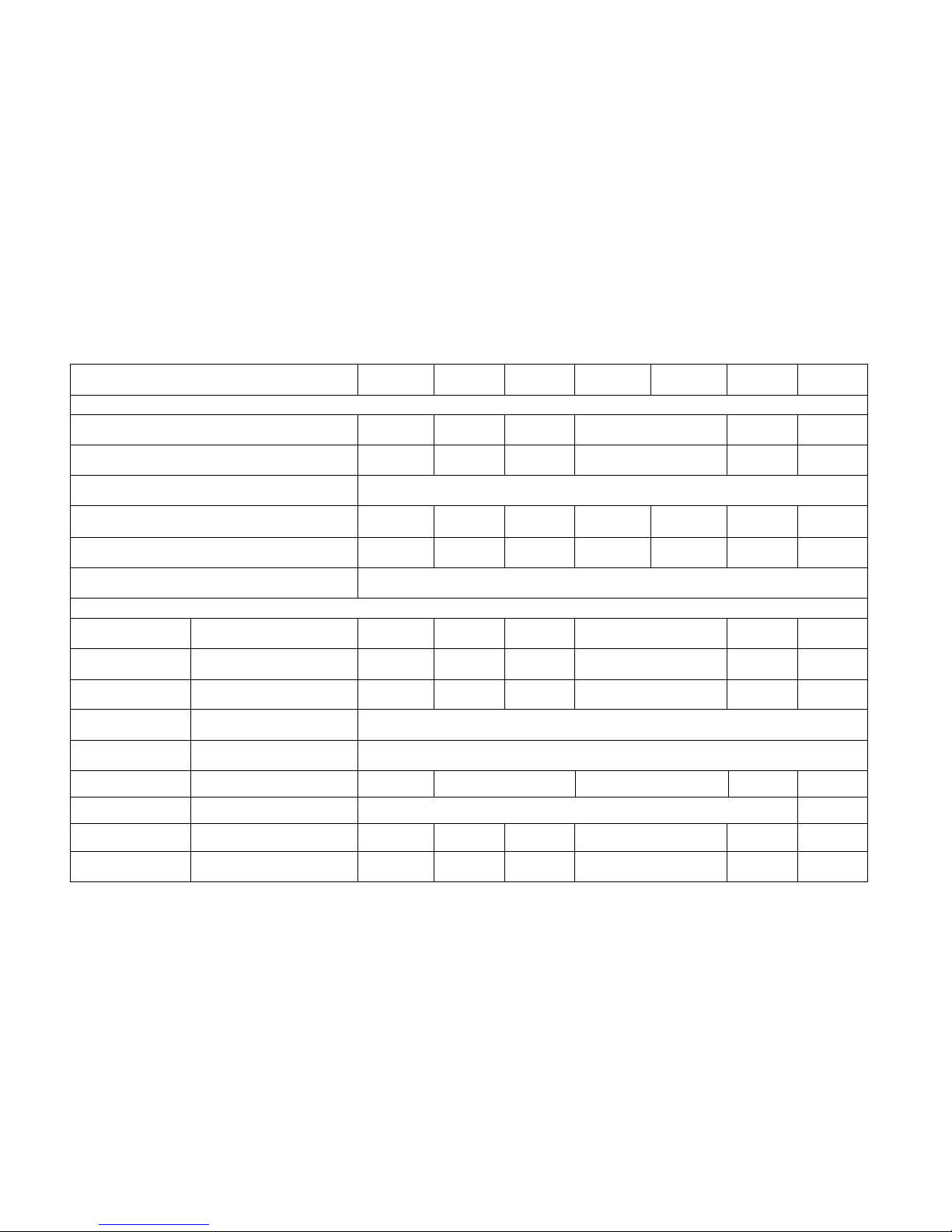
2.SPECIFICATIONS
Item PA10-5B PA18-1.2B PA18-2B PA18-3B PA18-5B PA36-1.2B PA36-2B PA36-3B
OUTPUT
Output voltage 0 to 10V 0 to 18V 0 to 36V
Resolution (logical value) 1.8mV 3.3mV 6.5mV
Voltage setting dial 10 Rotary
Output current 0 to 5A 0 to 1.2A 0 to 2A 0 to 3A 0 to 5A 0 to 1.2A 0 to 2A 0 to 3A
Resolution (logical value) 0.9mA 0.3mA 0.4mA 0.6mA 0.9mA 0.3mA 0.4mA 0.6mA
Current setting dial 10 Rotary
CONSTANT VOLTAGE CHARACTERISTICS (CV)
Input regulation
For ±10% variance of
source voltage *1
1mV 1mV 2mV
Load regulation
For 0V to 100% variance of
output current *1
5mV 2mV 2.5mV 3mV 5mV 2mV 3mV 4mV
Ripple and noise
rms(10Hz to 1MHz) *2
0.5mV
Transient response
typ(current 10% to 100%)
*3
50us typ
Temperature
coefficient
typ 100ppm/°C typ
Rise time
Full load/No load
typ
100ms/100ms
Fall time
Full load/No load
typ
50ms/1s
Remote control
External voltage/
output voltage ratio
Approx.
10V/10V
Approx. 10V/18V Approx. 10V/36V
Remote control
External resistance/
output voltage ratio
Approx.
10kΩ/10V
Approx. 10kΩ/18V Approx. 10kΩ/36V
3
Item PA80-1B PA120-0.6B PA160-0.4B PA250-0.25B PA250-0.42B PA350-0.2B PA600-0.1B
OUTPUT
Output voltage 0 to 80V 0 to 120V 0 to 160V 0 to 250V 0 to 350V 0 to 600V
Resolution (logical value) 14.4mV 21.6mV 28.8mV 45.0mV 63.0mV 108.0mV
Voltage setting dial 10 Rotary
Output current 0 to 1A 0 to 600mA 0 to 400mA 0 to 250mA 0 to 420mA 0 to 200mA 0 to 100mA
Resolution (logical value) 180uA 108uA 72uA 45uA 76uA 36uA 18uA
Current setting dial 10 Rotary
CONSTANT VOLTAGE CHARACTERISTICS (CV)
Input regulation
For ±10% variance of source
voltage *1
5mV 7mV 8mV 15mV 20mV 30mV
Load regulation
For 0V to 100% variance of
output current *1
5mV 7mV 8mV 15mV 20mV 30mV
Ripple and noise
rms(10Hz to 1MHz) *2
1mV 1.2mV 1.6mV 2.5mV 3.5mV 5mV
Transient response
typ(current 10% to 100%) *3
50us typ
Temperature
coefficient
typ 100ppm/°C typ
Rise time
Full load/No load
typ
100ms/
100ms
150ms/150ms 190ms/190ms
200ms/
200ms
330ms/
330ms
Fall time
Full load/No load
typ
50ms/1s 50ms/1.5s
Remote control
External voltage/
output voltage ratio
Approx.
10V/80V
Approx.
10V/120V
Approx.
10V/160V
Approx. 10V/250V
Approx.
10V/350V
Approx.
10V/600V
Remote control
External resistance/
output voltage ratio
Approx.
10kΩ/80V
Approx.
10kΩ/120V
Approx.
10kΩ/160V
Approx. 10kΩ/250V
Approx.
10kΩ/350V
Approx.
10kΩ/600V
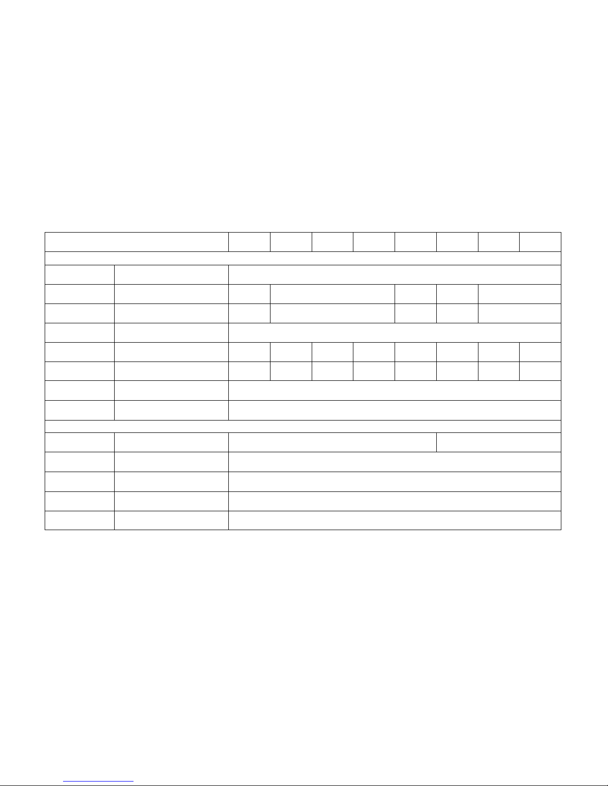
4
Item PA10-5B PA18-1.2B PA18-2B PA18-3B PA18-5B PA36-1.2B PA36-2B PA36-3B
CONSTANT-CURRENT CHARACTERISTICS (CC)
Input regulation
For ±10% source voltage
fluctuation *1
2mA
Load regulation
For 0V to 100% variance of
output voltage *1
5mA 5mA 5mA 5mA 5mA
Ripple and noise rms (10 Hz to 1 MHz) *2 5mA 1mA 5mA 1mA 2mA
Temperature
coefficient
typ 250ppm/°C typ
Remote control
External voltage to output
current ratio
Approx.
10 V/5 A
Approx.
10 V/1.2A
Approx.
10 V/2 A
Approx.
10 V/3 A
Approx.
10 V/5 A
Approx.
10 V/1.2A
Approx.
10 V/2 A
Approx.
10 V/3 A
Remote control
External resistance to output
current ratio
Approx.
10 kΩ/5 A
Approx.
10k Ω/1.2A
Approx.
10 kΩ/2 A
Approx.
10 kΩ/3 A
Approx.
10 kΩ/5 A
Approx.
10k Ω/1.2A
Approx.
10 kΩ/2 A
Approx.
10 kΩ/3 A
Constant-voltage
operation display
Off when output is off CV (green LED) is on.
Constant-current
operation display
Off when output is off CC (red LED) is on.
DIDITAL METER DISPLAY
Voltmeter display 3 1/2-digit LEDs, red 19.99 V max., fixed range 19.99V/199.9V max., auto range
Accuracy Output on ±(0.2% rdg + 1 digit), 23 ±5°C, 80%RH or less
Ammeter display 3-digit LEDs, red 9.99 A max., fixed range
Accuracy Output on *4 ±(1.0% rdg + 2 digits), 23 ±5°C, 80%RH or less
Sampling rate Approx. 2.5 times/sec. or more

5
Item PA80-1B PA120-0.6B PA160-0.4B PA250-0.25B PA250-0.42B PA350-0.2B PA600-0.1B
CONSTANT CURRENT CHARACTERISTICS (CC)
Input regulation
For ±10% source voltage
fluctuation *1
2mA 1mA 0.5mA 1mA 0.5mA
Load regulation
For 0V to 100% variance of
output voltage *1
5mA 5mA 5mA 5mA 5mA 2.5mA
Ripple and noise
rms(10Hz to 1MHz)
*2
2mA 1mA
Temperature
coefficient
typ 250ppm/°C typ
200ppm/°C typ
250ppm/°C
typ
200ppm/°C typ
Remote control
External voltage to output
current ratio
Approx.10V/1A
Approx.
10V/0.6A
Approx.
10V/0.4A
Approx.
10V/0.25A
Approx.
10V/0.42A
Approx.
10V/0.2A
Approx.
10V/0.1A
Remote control
External resistance to output
current ratio
Approx.
10kΩ/1A
Approx.
10kΩ/0.6A
Approx.
10kΩ/0.4A
Approx.
10kΩ/0.25A
Approx.
10kΩ/0.42A
Approx.
10kΩ/0.2A
Approx.
10kΩ/0.1A
Constant-voltage
operation display
Off when output is off CV (green LED) is on.
Constant-current
operation display
Off when output is off CC (red LED) is on.
DIDITAL METER DISPLAY
Voltmeter display 3 1/2-digit LEDs, red
199.9/999 V
max.,auto range
199.9 V max., fixed range
199.9/999 V max., auto range
Accuracy Output on
±(0.2% rdg + 1
digit), 23 ±5°C,
80%RH or less
±(0.2% rdg + 2 digit), 23 ±5°C, 80%RH or less
Ammeter display 3-digit LEDs, red
9.99A max.,
fixed range
999mA max., fixed range
Accuracy Output on *4
±(1.0% rdg + 2
digit), 23 ±5°C,
80%RH or less
±(1.0% rdg + 3 digit), 23 ±5°C, 80%RH or less
Sampling rate Approx. 2.5 times/sec. or more

6
Item PA10-5B PA18-1.2B PA18-2B PA18-3B PA18-5B PA36-1.2B PA36-2B PA36-3B
FUNCTIONS
OVP ALARM LED goes on Approx. 5 to 105%
OHP ALARM LED goes on
Output goes off when internal heat sink temperature reaches 105 ±5°C.
(Only PA18-5B,PA36-3B are 110°C)
Output switch Remote on/off control
Output may be turned on or off with remote control switch on rear panel.
(Front/rear control is selected with switch on front panel.)
V/I check switch Indicator indicates constant-voltage or constant-current set value when switch is turned on.
Remote sensing Enabled with (+S) and (-S) terminals on front panel. May correct up to 0.5 V, one way. *5
Voltage monitor
Output voltage to monitor
voltage ratio
Output voltage 0 to rated voltage/approx. 0 to 10 V output (Connector on rear panel)
Current monitor
Output current to monitor
voltage ratio
Output current 0 to rated current/approx. 0 to 10 V output (Connector on rear panel)
Status signal CV Open collector output, Low in CV mode
CC Open collector output, Low in CC mode
ALARM Open collector output, Low in alarm mode
Parallel operation
Master/slave system
Capable of one-control parallel operation.
(Current error: ±20%, up to 3 units. One-control is applicable to same models only.)

7
Item PA80-1B PA120-0.6B PA160-0.4B PA250-0.25B PA250-0.42B PA350-0.2B PA600-0.1B
FUNCTIONS
OVP ALARM LED goes on Approx. 5 to 105%
OHP ALARM LED goes on
Output goes off when internal heat sink temperature reaches 105 ±5°C.
(Only PA250-0.42B is 110°C)
Output switch Remote on/off control
Output may be turned on or off with remote control switch on rear panel.
(Front/rear control is selected with switch on front panel.)
V/I check switch Indicator indicates constant-voltage or constant-current set value when switch is turned on.
Voltage monitor
Output voltage to monitor
voltage ratio
Output voltage 0 to rated voltage/approx. 0 to 10 V output (Connector on rear panel)
Current monitor
Output current to monitor
voltage ratio
Output current 0 to rated current/approx. 0 to 10 V output (Connector on rear panel)
CV Open collector output, Low in CV mode
CC Open collector output, Low in CC mode
Status signal
ALARM Open collector output, Low in ALARM mode
Parallel operation Master/slave system
Capable of one-control parallel operation.
(Current error: ±20%, up to 3 units. One-control is applicable to same models only.)

8
Item PA10-5B PA18-1.2B PA18-2B PA18-3B PA18-5B PA36-1.2B PA36-2B PA36-3B
OPERATING CONDITIONS
Operating temperature/humidity range 0 to 40°C 10% to 80%RH
Storage temperature/humidity range -20 to 60°C 10% to 85%RH
Cooling method Natural convection
Output polarity Positive or negative grounding possible
Ground proof voltage ±250VDC
Between the chassis and
input power supply terminal
DC500V 30MΩor more
Insulation
resistance
Between the chassis and
Output terminal
DC500V 20MΩor more
Insulated
resisting pressure
Between the chassis and
input power supply terminal
AC1.5kV /1 minute
POWER REQUIREMENTS
Input Voltage, frequency
AC220V±10%、50/60Hz、1φ
Power consumption(VA)
At the time of AC rated input
Approx.
150VA
Approx.
60VA
Approx.
100VA
Approx.
140VA
Approx.
210VA
Approx.
105VA
Approx.
165VA
Approx.
220VA
Power consumption(W)
At the time of AC rated input
Approx.
120W
Approx.
50W
Approx.
75W
Approx.
110W
Approx.
165W
Approx.
80W
Approx.
130W
Approx.
170W
DIMENSIONS AND WEIGHT
Dimensions(mm)
104×124
×350
104×124×270 104×124×350
104×124
×270
104×124×350
Max. dimensions(mm)
106.2×144.3
×368.3
106.2×144.3×288.3 106.2×144.3×368.3
106.2×144.3
×288.3
106.2×144.3×368.3
Weight
Approx.
6.6kg
Approx.
4.7kg
Approx.
4.7kg
Approx.
6.6kg
Approx.
6.6kg
Approx.
4.7kg
Approx.
6.6kg
Approx.
6.6kg
ACCESSORIES
One instruction manual, One adjustment driver, One power cable(3P)

9
Item PA80-1B PA120-0.6B PA160-0.4B PA250-0.25B PA250-0.42B PA350-0.2B PA600-0.1B
OPERATING CONDITIONS
Operating temperature/humidity range 0 to 40°C 10% to 80%RH
Storage temperature/humidity range -20 to 60°C 10% to 85%RH
Cooling method Natural convection
Output polarity Positive or negative grounding possible
Ground proof voltage ±250VDC
±500VDC ±600VDC
Between the chassis and
input power supply
terminal
DC500V 30MΩor more
Insulation
resistance
Between the chassis and
Output terminal
DC500V 20MΩor more
DC600V
20MΩ
or more
Insulated
resisting pressure
Between the chassis and
input power supply terminal
AC1.5kV /1 minute
POWER REQUIREMENTS
Input Voltage, frequency
AC220V±10%、50/60Hz、1φ
Power consumption(VA)
At the time of AC rated input
Approx.
170VA
Approx.
155VA
Approx.
150VA
Approx.
140VA
Approx.
220VA
Approx.
150VA
Approx.
130VA
Power consumption(W)
At the time of AC rated input
Approx.
140W
Approx.
115W
Approx.
100W
Approx.
105W
Approx.
150W
Approx.
110W
Approx.
100W
DIMENTIONS AND WEIGHT
Dimensions(mm)
104×124×350
Max. dimensions(mm)
106.2×144.3×368.3
Weight
Approx.
6.6kg
Approx.
6.6kg
Approx.
6.6kg
Approx.
6.6kg
Approx.
6.6kg
Approx.
6.6kg
Approx.
6.6kg
ACCESSORIES
One instruction manual, One adjustment driver, One power cable(3P)
*1: By LCL (internal sensing) at the sensing terminal.
*2: Measurement is done by ground either positive or negative output.
*3: Responding time when output voltage returns to within 0.05%+10mV of the rating at ON.
*4: After worm up for approximately 30 minutes when the current is fed.
*5: When the power supply output is rated value or less.

10
3. INSTRUCTIONS ON USE
Be sure to read through the instructions shown below prior to
using the PA-B series.
WARNING
3-1. Checking Source Voltage
* Be sure to connect the PA-B series with a commercial power
supply of the rated voltage.
* The rated voltage is shown on the rating nameplate near the
AC inlet on the rear panel.
3-2. Connection of Power Cable
* Connect the power cable plug firmly into the AC outlet that
carries the rated voltage.
CAUTION
3-3. Precautions for Connecting Output Terminals
* The PA-B series is a floating type power supply unit.
Normally, connect either the (+) or (-) output terminal on the
front panel with the GND terminal (case GND) using a
shorting bar.
* The (+S) and (-S) terminals and switch on the front panel are
used for remote sensing (PA10-5B, PA18-1.2B, PA18-2B,
PA18-3B, PA18-5B, PA36-1.2B, PA36-2B and PA36-3B only).
Normally, set the switch to the LCL position and connect
nothing with the terminals. If the switch is set to the REM
position, the voltage sensing circuit is disconnected internally,
resulting in erroneous output voltage indication.
For remote sensing connection, see section 5-2 "Remote
Sensing" below.

11
3-4.Switches on Front Panel and Connection Terminals on
Rear Panel
* Make sure that the MASTER/SLAVE selector switch on the
front panel is set to the M position.
* Make sure that the OUTPUT SW F/R selector switch on the
front panel is set to the F position.
* Make sure that all remote selector switches on the front panel
are set to the Off positions.
* Connect nothing with the connection terminals on the rear
panel unless the master/slave mode, remote control mode or
the like is selected.
3-5.Digital Display
* Digital display of the PA-B series is subject to 1-digit
fluctuations, which depend on the performance of the A/D
converter. Such fluctuations do not imply ripples or noises in
output.
* Display may become unstable if the available commercial
power source contains much common mode noises or there is
an intense noise source near the PA-B series. Be very
careful.
3-6. Switching Points of Relay
* The PA-B series switches the secondary taps of the internal
transformer using a relay and changes the input voltage to the
series regulator in order to reduce internal losses. It has
three relay switching points, which vary with the input voltage.
* If the input voltage varies when the preset output voltage is
close to the relay switching point, the relay switches and a
relay switching sound may be heard. (This implies no
trouble.) Noises may be generated at the relay switching
point when the output increases, depending on input voltage
(low voltage) or load conditions.

12
3-7. Installation Environments
* Use the PA-B series in the ambient temperature range from 0
to +40°C.
* The PA-B series is a natural air cooling type power supply unit.
Do not put any object on it, place it on a heat-generating
object, or stack several PA-B units. Use the PA-B series in a
place having as good ventilation as possible.
* The heat sink built in the PA-B series may become hot during
operation. Be very careful about ventilation. Do not place
any object easily affected by heat near the PA-B series.
* As the built-in heat sink overheats, the case of the PA-B
series may become hot. If it is necessary to touch the case
or move the PA-B series, turn off power and wait for a mean
while (until the case cools down).
HOT BE CAREFUL

13
3-8. Rack Mounting
* Contact the our distributor if you need the rack mounting kit.
* The PA-B series is a natural air cooling type power supply unit.
Proper heat radiation measures are needed when mounting it
on a rack. Leave sufficient spaces above and below the unit
mounted on a rack and take the proper heat radiation
measures in order to prevent the temperature in the rack
(ambient temperature) from exceeding the allowable
temperature range. The OHP may work if the temperature
exceeds the allowable temperature range.
HOT BE CAREFUL

14
3-9. Options
The guard cap and handle for the PA-B series are available by
option. (The handle is mounted in the factory.) Contact our
distributor for details.
* Guard cap (OP-20GC)
The guard cap is to be replaced with the knob to prevent the
preset voltage or current from being changed by mistake.
* Handle (XO-PA10, factory option)
The optional handle may be mounted to the PA18-1.2B,
PA18-2B or PA36-1.2B only. The other models have handles
as the standard features.
The handles enhance movement of the PA-B series.
① Handle
② Cap
④ Flat head screws
⑤ Flange nuts
φ13
(13.34)
φ12.2
12.9
③ Brackets

15
4.PANEL EXPLANATION

16
4-1. Front panel
1. POWER ON/OFF
The power switch of the PA-B series.
Set the switch to ON to turn on power. When power is turned
on, the PA-B series runs.
2. OUTPUT key and OUTPUT LED (red)
The output On/Off switch of the PA-B series.
Press the OUTPUT key to turn on the output (and the OUTPUT
LED goes on). The voltmeter and ammeter indicate the output
values at that time.
When the OUTPUT key is pressed while the OUTPUT LED is lit,
the OUTPUT LED goes out and the output is shut off.
NOTE 1: When the PA-B series is turned on, the OUTPUT LED
and output are always off.
NOTE 2: When the OUTPUT F/R selector switch on the front
panel is set to the R position, the OUTPUT key is
disconnected and the output is set to the Off condition.
If the PA-B series is turned on in this condition, the
output is turned off.
3. Digital voltmeter (3 1/2-digit LEDs, red)
This voltmeter displays the output voltage or the set voltage
(only when the V/I check key on the front panel is pressed).
4. Digital ammeter (3-digit LEDs, red)
This voltmeter displays the output current or the set current
(only when the V/I check key on the front panel is pressed).
5. CV LED (green)
The constant-voltage mode indicator LED.
It is lit when the PA-B series is in the constant-voltage mode.
6. CC LED(red)
The constant-current mode indicator LED.
It is lit when the PA-B series is in the constant-current mode.

17
7. ALARM LED(red)
The alarm status indicator LED.
It is lit when the over-voltage or overheat protection circuit works
and turns off the output. Press the POWER ON/OFF switch to
turn off power once, eliminate the alarm cause, and turn on
power again.
8. V/I CHECK key
This key is used to display the set voltage and set current.
The voltmeter displays the set voltage and the ammeter displays
the set current while the key is held.
NOTE: When this key is pressed, the minimum digit of the
voltmeter becomes 100 mV (or 10 mV on a model of
18 V rating).
9. VOLTAGE control
This control is used to set the voltage in constant-voltage
operation. It varies and sets the limit value of the output voltage.
10. CURRENT control
This control is used to set the current in constant-current
operation. It varies and sets the limit value of the output current.
11. Output terminal (+)
Positive (+) output is given through this terminal.
12. Output terminal (-)
Negative (-) output is given through this terminal.
13. GND terminal
This grounding terminal is connected with the frame. Connect
a shorting bar between the GND terminal and (+) or (-) output
terminal normally.
14. Shorting bar
The shorting bar is normally used to connect the GND terminal
and (+) or (-) output terminal.

18
15. Remote sensing (PA10-5B, PA18-1.2B, PA18-2B, PA18-3B,
PA18-5B, PA36-1.2B, PA36-2B and PA36-3B)
・ REM/LCL selector switch
This switch is normally set to the LCL (internal sensing) position.
Set it to the REM position to execute remote sensing.
NOTE: Do not set this switch to the REM position unless the
remote sensing function is used. Connect the sensing
cable and load cable firmly to prevent them from being
disconnected during sensing.
・ +S terminal
The (+) output remote sensing terminal.
・ -S terminal
The (-) output remote sensing terminal.
16. OVP control
This control is used to set the operating voltage of the OVP
(over-voltage protection) circuit.
17. MASTER/SLAVE selector switch
This selector switch is used to carry out one-control parallel
operation in the master/slave mode. Set it to the MASTER
position normally. (For details, see section 5-11 "One-Control
Parallel Operation" below.)
18. Rear panel control selector switch
This switch selects the constant-voltage, constant-current and
output on/off remote controls. Set it to the OFF position
normally. Operations on the front panel are enabled at this
position. Remote controls are enabled at other positions.
(For details, see section 5 "OPERATION PROCEDURES" below.)
19. Rear panel control volume
This volume is used for remote constant-voltage and constantcurrent controls.
(For details, see section 5 "OPERATION PROCEDURES" below.)

19
4-2.Rear panel
20. MASTER/SLAVE connection terminals
These terminals are used for one-control parallel operation in the
master/slave mode. (For details, see section 5-11 "One-Control
Parallel Operation" below.)
21. Rear panel remote control terminals
These terminals are used for constant-voltage, constant-current
and output on/off remote controls. (For details, see section 5
"OPERATION PROCEDURES" below.)
22. Status signal output terminals
These terminals output the CV, CC and ALARM status signals.
(For details, see section 5-8 "Status Signals" below.)
23. Voltage and current monitor signal output terminals
These terminals output the monitored voltage and current of the
PA-B series in voltages. (For details, see section 5-9 "Monitoring
Voltage and Current" below.)
24. AC inlet
The AC inlet connector of the PA-B series.
25. Input AC voltage selector switches
The 2 combination switches are located in the rear panel of
the unit to select the input AC voltage. Set them as shown
below to select AC 100V, 110V, 200V or 220V. However, it
becomes a switch of AC100V, 115V, 200V, and 230V
according to the model. Which voltage can be set is
displayed in rear panel of the PA-B SERIES. (Please refer to
the table for the A. Voltage setting table)
Use 115V for actual 120V AC operation.

20
A. Voltage setting table
WARNING
NOTE: Be sure to disconnect the AC power cable before setting the
input AC voltage.
Be sure to use the proper fuse as shown below.
10-5 18-1.2 18-2
18-3
18-5 36-1.2 36-2
36-3
Fuse
(time-lag)
100/200 VAC
3A/
2A
1.5A/
0.8A
2A/
1.25A
3A/
2A
5A/
3A
2.5A/
1.5A
3A/
2A
5A/
3A
80-1 120-0.6 160-0.4 250-0.25 250-0.42 350-0.2 600-0.1
Fuse
(time-lag)
100/200 VAC
3A/2A 3A/2A
3A/2A
3A/2A 4A/2.5A
3A/2A
3A/
2A
26. Fuse holder
The AC input fuse is built in this holder.
27. Frame GND terminal screw
Use this screw to ground the frame of the PA-B series. Never
use any other screw. Using any other screw may cause
short-circuit inside the PA-B series, resulting in malfunctioning or
breakdown.

21
5. OPERATION PROCEDURES
5-1.Independent Operation
*Use the switches and terminals on the front panel to use the PA-B
series alone.
*Make sure that the switches on the front panel are set as shown
below.
OUTPUT switch :F (front) position
MASTER/SLAVE switch :M (master) position
Various control ON/OFF switches :OFF positions
5-2.Remote Sensing
*When the PA-B series is connected with a load, the voltage at the
load terminals is subject to load variance, which depends on the
voltage drop caused by contact resistance of the output terminals or
resistance of the load cable conductors.
Set the remote sensing selector switch on the front panel to the
REM position, connect wires to the (+S) and (-S) remote sensing
terminals and carry out remote sensing operation, if it is necessary
to set the voltage at the load terminals finely.
*The PA-B series compensates for voltage drop of the load cable up
to 0.5 V (one way).
*Do not set the selector switch to the REM position in normal
operation without using the remote sensing function.

22
CAUTION
- This function is available in the PA10-5B, PA18-1.2B, PA18-2B,
PA18-3B, PA18-5B, PA36-1.2B, PA36-2B and PA36-3B only.
- If no remote sensing cable is connected despite the fact that the
remote sensing selector switch is set to the REM position, the
output voltage may be too high and the load may be broken. Be
sure to set the selector switch to the LCL position when remote
sensing is not carried out.
- If the load is too apart from the PA-B series, inductance and
capacitor of the load cable may cause oscillation. Connect an
electrolytic capacitor of approximately 100 µF to the load
terminals in such a case.
5-3.OVP
*The OVP protects the load from over-load. The ALARM LED
goes on when the OVP circuit works. Shut off the POWER
switch once and turn it on again to reset the alarm.
1) Turn the OVP control fully clockwise with the adjustment
screwdriver supplied with the PA-B series.
2) Output the limit voltage for over-voltage protection. Turn the
OVP control counterclockwise slowly with the adjustment
screwdriver until the OVP circuit works.
3) Cut off output when the voltage between the output terminals of
the PA-B series reaches the preset OVP value.
+
-
+S
-S
Load
Vo
Vo ≦ Rated voltage
Use a shielded cable or twisted pair wires.

23
5-4.Remote Control Functions
1. Remote control application functions
The switches on the front panel are set as shown below by default.
2. Remote control applications
Remote functions
Operation types
MASTER
/SLAVE
CV
REMOTE
voltage or
resistance
CC
REMOTE
voltage or
resistance
OUTPUT
ON/OFF
Independent operation Set to M
○ ○ ○
MASTER
Set to M
○ ○ ○
One-control
parallel operation
SLAVE Set to S
× × ○
○ : Remote control is available.
× : Remote control is not available.
V ext.R
Output voltage control
by external resistance
I ext.R
Output current control
by external resistance
OUTPUT SW
control
OUTPUT
SW
R
F
MASTER
/SLAVE
S
M
One-control operation
in parallel connection
Output voltage control
by external voltage
V ext.V
ON
OFF
I ext.V
Output current control
by external voltage

24
3. Usage of connection terminals on rear panel
Follow the procedures shown below to connect the cables to the
terminals on the right of the rear panel.
1) Apply a flathead screwdriver (thin screwdriver) to the slit on the
right of the round (or square) hole for connecting a cable.
Press it and insert the cable conductor into the round (or
square) hole.
2) Disconnect the cable in the same manner. Press the slit with
the screwdriver and pull out the cable.
NOTE: Applicable wires:Solid wire: 0.4 to 1.0 mm dia. (AWG26 to 18)
Braided wire: 0.3 to 0.75 mm²
(AWG22 to 20)
Element wire: 0.18 mm dia. or more
Standard peel-off length: 10 mm (Solder the peeled conductors
of a braided wire.)
4. GP-IB control
*It is possible to set the constant-voltage and constant-current
values and control the OUTPUT switch of the PA-B series from
a computer through the GP-IB bus (in conformity to
IEEE-488-1978) if the optional GP-IB adapter GP-600B is used.
*A single GP-600B may control the following of each PA-B unit.
- Output voltage and current setting
- OUTPUT ON/OFF
- ALARM detection
- CV CC, CC CV mode interrupt
1) Press with the screwdriver.
2) Insert the cable

25
5-5.Output ON/OFF Remote Control
*It is possible to control output On/Off using external contact
signals as shown below
1) Shut off the POWER switch.
2) Set the OUTPUT SW on the front panel to the R position with
the attached adjustment screwdriver, and connect the cable to
the terminals on the rear panel as shown below.
OUTPUT terminals Output
Short ON
Open OFF
The OUTPUT key on the front panel is not active.
NOTES:
- Float the potential of the external contact signal from the potentials
of the (+) and (-) outputs and GND (case GND). ON/OFF control
using a photo-coupler is also enabled.
- 0.5 mA, 5 V max. output is applied to the external contacts.
※Selecting output ON and output fixing
- If the OUTPUT SW is set to the R position and the OUTPUT
terminals on the rear panel are short-circuited, the output is turned on
continuously.
In this condition, the output is turned on when the PA-B series is
turned on.
ON
OFF
OUTPUT1
OUTPUT
SW
R
F
Front panel switch
OUTPUT2
Terminals on rear panel
Or

26
5-6.Constant-Voltage Remote Control
1. Output voltage control using external voltage
*It is possible to control the output voltage using 0 to 10 V
external voltage.
1) Shut off the POWER switch.
2) Set the offset and FS switches of "V ext. V" on the front
panel to the ON positions with the attached screwdriver.
Connect a cable to the terminals on the rear panel as shown
below.
Relationship between output voltage (E0) and external voltage (E1)
E0: Output voltage
E0≒ × E1 [V] (0≦E1≦10V) Emax: Rated voltage
E1: External voltage
3) Adjustment procedures
- Apply 0.1 V between the "ext. cont. V" V+ terminal and
"ext. cont. V" - (-S) terminal on the rear panel.
- Press the OUTPUT key to turn on power.
- Rotate the V offset control on the front panel with the
attached adjustment screwdriver to adjust the output voltage
to 1% of the rated voltage.
- Then, apply 10 V between the "ext. cont. V" V+ terminal and
"ext. cont. V" - (-S) terminal on the rear panel.
- Rotate the V FS control on the front panel with the attached
adjustment screwdriver to adjust the output voltage to 100%
of the rated voltage.
E
max
10
Front panel switches and controls
V ext.V
V offset
V FS
ON
OFF
Terminals on rear panel
ext.cont
V
E1
Use a shielded cable or twisted pair wires.
.V-(-S)
.V+

27
NOTES:
- The negative (-) potential of the external voltage (E1) represents the
voltage at the (-) output terminal. The negative (-) potential of the
internal control voltage also represents the voltage at the (-) output
terminal. Therefore, be very careful when grounding the output.
- Ripples and noises contained in the external voltage are amplified
and output. Thus, use external voltage with less ripples and
noises.
- The input impedance (Zin) of E1 is approximately 10 kΩ.
- Supply E1 using a two-core shielded cable or stranded (+) and (-)
twist pair wires.
2. Output voltage control using external resistance
* It is possible to output voltage in proportion to resistance
between 0 to 10 kΩ.
1) Shut off the POWER switch.
2) Set the V ext. R switch on the front panel to the ON position
with the attached screwdriver. Then, connect a cable to the
terminals on the rear panel as shown below.
Relationship between output voltage (E0) and external resistance (VR1)
E
0
: Output voltage
E0≒ × VR1 [kΩ] (VR1≦10kΩ) E
max
: Rated voltage
VR1 :External resistance
Front panel switch and control
Terminals on rear panel
V
R1
R2
V ext.R
ON
OFF
ext.cont
Use a shielded cable or twisted pair wires.
VR1
E
max
10

28
3) Adjustment procedures
- Connect an external resistor VR1 between the "V ext. cont." R1
terminal and "V ext. cont." R2 terminal on the rear panel.
- Set the VR1 to 10 kΩ.
- Press the OUTPUT key to turn on power.
- Rotate the V FS control on the front panel with the attached
adjustment screwdriver to adjust the output voltage to the rated
voltage.
NOTE:
- The potential at the terminals of the external resistor (VR1) should
be floated from the (+) and (-) output and GND potentials.
- As VR1, use a variable resistor which is free from aged
deterioration and noises and has a temperature coefficient of
approximately 100 ppm/°C and capacity of 1/2 W or more.
- Connect VR1 with a two-core shielded cable or stranded (+) and (-)
twist pair wires.
CAUTION
- If VR1 is opened, over-voltage is output.
- When changing the resistance using a switch or the like, it should
be a short circuit type switch that does not make the circuit open.
- Do not set the V ext. R switch to the ON position in the condition
where the output is on. Otherwise, voltage exceeding the
maximum rating is applied to the output, resulting in breakage of
the load.
V FS
Front panel

29
5-7.Constant-Current Remote Control
1. Output current control using external voltage
*It is possible to control the output current using 0 to 10 V
external voltage.
1) Shut off the POWER switch.
2) Set the offset and FS switches of "I ext. V" on the front panel
to the ON positions with the attached screwdriver. Connect a
cable to the terminals on the rear panel as shown below.
Relationship between output current (I0) and external voltage (E2)
I0 :Output current
Ⅰ0≒ × E2 [V] (0≦E2≦10V) I
max
:Rated current
E2 :External voltage
3) Adjustment procedures
- Apply 0.1 V between the "ext. cont. I" V+ terminal and "ext.
cont. I" V- (-S) terminal on the rear panel.
- Press the OUTPUT key to turn on power.
- Rotate the I offset control on the front panel with the attached
adjustment screwdriver to adjust the output current to 1% of
the rated current.
- Then, apply 10 V between the "ext. cont. I" V+ terminal and
"ext. cont. I" V- (-S) terminal on the rear panel.
- Rotate the I FS control on the front panel with the attached
adjustment screwdriver to adjust the output current to 100% of
the rated current.
I
max
10
Front panel switches and
I ext.V
I offset
I FS
ON
OFF
Terminals on rear panel
ext.cont
I
E2
Use a shielded cable or twisted pair wires.
.V-(-S)
.V+

30
NOTES:
- The negative (-) potential of the external voltage (E2)represents
the voltage at the (-) output terminal. Therefore, be very careful
when grounding the output.
- Ripples and noises contained in the external voltage are amplified
and output. Thus, use external voltage with less ripples and noises.
- The input impedance (Zin) of E2 is approximately 10 kΩ.
- Supply E2 using a two-core shielded cable or stranded (+) and (-)
twist pair wires.
2. Output current control using external resistance
* It is possible to output current in proportion to resistance
between 0 to 10 kΩ.
1) Shut off the POWER switch.
2) Set the I ext. R switch on the front panel to the ON position
with the attached screwdriver. Then, connect a cable to the
terminals on the rear panel as shown below.
Relationship between output current (I0)and external resistance (VR2)
I0 :Output current
I0≒ × VR2 [kΩ] (VR2≦10kΩ) I
max
:Rated current
VR2 :External resistance
I
max
10
Use a shielded cable or twisted pair wires.
I ext.R
ON
OFF
Terminals on rear panel
ext.cont
I
R2
R1
VR2
Front panel switch and control

31
3) Adjustment procedures
- Connect an external resistor VR2 between the "I ext. cont." R1
terminal and "I ext. cont." R2 terminal on the rear panel.
- Set the VR2 to 10 kΩ.
- Press the OUTPUT key to turn on power.
- Rotate the I FS control on the front panel with the attached
adjustment screwdriver to adjust the output current to the rated
current.
NOTES:
- The potential at the terminals of the external resistor (VR2) should
be floated from the (+) and (-) output and GND potentials.
- As VR2, use a variable resistor which is free from aged deterioration
and noises and has a temperature coefficient of approximately
100 ppm/°C and capacity of 1/2 W or more.
- Connect VR2 with a two-core shielded cable or stranded (+) and
(-) twist pair wires.
CAUTION
- If VR2 is opened, over-current is output and the PA-B series may
be damaged.
- When changing the resistance using a switch or the like, it should
be a short circuit type switch that does not make the circuit open.
- Do not set the I ext. R switch to the ON position in the condition
where the output is on. Otherwise, current exceeding the
maximum rating is output, resulting in breakage of the load.
Front panel
I FS

32
5-8.Status Signals
1. CV operation status output signal
This signal is active while the PA-B series is running in the CV
(constant-voltage) mode.
2. CC operation status output signal
This signal is active while the PA-B series is running in the CC
(constant-current) mode.
3. ALARM status output signal
This signal goes active when the PA-B series enters an alarm
status. It enters the alarm status and turns off output if the
OVP or OHP circuit works.
NOTE: The status signal output terminals shown above are
connected with the transistors at the light receiving elements
of the photo-couplers (TOSHIBA TLP521-1) inside the PA-B
series. See the photo-coupler ratings shown below and use
these signals properly.
※ Maximum rating of photo-coupler TLP521-1
Item Symbol Max. rating
Unit
Collector-emitter voltage
V
CEO
55 V
Emitter-collector voltage
V
ECO
7 V
Collector current
IC 50 mA
Output
Collector loss
PC 150 mW
Total allowable loss
PT 250 mW
Dielectric strength voltage
BVS 2500 Vrms
CC
CV
COMMON
Connection terminals on rear panel

33
5-9. Monitoring Voltage and Current
*It is possible to monitor the output voltage and current of the
PA-B series in terms of voltages.
1) Shut off the POWER switch.
2) Connect a voltage monitoring meter between the V MONITOR
+ terminal and V MONITOR -(-S) terminal on the rear panel.
Connect a current monitor meter between the I MONITOR +
terminal and I MONITOR - (-S) terminal.
3) Throw the POWER switch to turn on power.
4) When the output voltage is in the range between 0 V and the
rated voltage, voltage between 0 and approximately 10 V is
output through the V MONITOR + terminal and V MONITOR
-(-S) terminal.
5) When the output current is in the range between 0 A and the
rated current, voltage between 0 and approximately 10 V is
output through the I MONITOR + terminal and I MONITOR
-(-S) terminal.
NOTE: The V MONITOR - (-S) and I MONITOR - (-S) terminals are
connected together internally. The -S terminal is connected
with the frame GND through the shorting bar. Use the
monitor meters in the floated condition to avoid accidents or
malfunctioning. These monitor terminals may not be used to
observe waveforms.
Voltage monitoring
Current monitoring
Connection terminals on rear panel
V MONITO
R+
I MONITOR+
V MONITOR-(-S)
I MONITOR-(-S)
-S
M
+
-
M
+
-

34
5-10.Series and Parallel Connections
1. Series connection
*It is possible to increase the output voltage by connecting two or
more PA-B power supply units.
- In the connection example shown below, the total output voltage
is the sum of the output voltage of each PA-B power supply unit.
(Left figure)
- In the connection example shown below, the positive and
negative powers are output. (Right figure)
NOTE 1: In series connection, the voltage at the output terminals
must not exceed the withstand grounding voltage (between
the output terminals and frame GND). Be very careful.
NOTE 2: Connect the GND terminals of the PA-B power supply units
together with an intended potential to eliminate the potential
among the frame grounds of the power supply units.
(The above drawing shows the negative (-) grounding.)
NOTE 3: Do not connect the PA350-0.2B and PA600-0.1B in series.
NOTE 4: Be sure to float the control input of each power supply unit
when using the external control function.
Load
+
- E
E1
E
E0=E1+E2
+
- G
+
-
G
Load
+
+E
Load
-
E2
E0=+E1
E0=-E2
+
-
G
+
G

35
2. Parallel connection
*It is possible to increase the output current by connecting two or
more PA-B power supply units in parallel.
*Constant-voltage (CV) application
Make the output voltage of each power supply unit equal.
Difference in the output voltages (like E1 > E2) will result in
fluctuations for the load.
①Current is supplied from E1 first.
②When the current enters the constant-current (CC) zone and
the output voltage lowers,
③E2 begins to supply current then.
*Constant-current (CC) application
Make sure that the CC LED on each power supply unit is lit.
The total output current is the sum of the output current of each
power supply unit.
NOTE 1: Do not apply any voltage exceeding the rated voltage to the
output of each power supply unit.
NOTE 2: Current of several mA flows back to the power supply unit
with lower output voltage.
+
-
+
-
E1 E2
I2 I1
E0=E1=E2
I0=I1+I2
G G
E0
I0
①
E2
E1
E0
I0
I1 I2
②
③

36
5-11.One-Control Parallel Operation
*It is possible to control units connected in parallel (i.e., two slave
units) and increase their output capacity from one unit (master unit).
*The total output current capacity is the sum of the output current
of each slave unit.
1) Turn off power of all master and slave units.
2) Set the MASTER/SLAVE switches on the front panels of all
slave units to the S position.
3) Connect the parallel operation terminals (IN/OUT1/OUT2) on
the rear panels of the master and slave units as shown in the
drawing.
4) Connect the output terminals of the power supply units with the
load using cables of the same length as shown in the
connection diagram.
5) Rotate the voltage control of all slave units fully clockwise.
6) Throw the POWER and OUTPUT switches of the slave units.
7) Throw the POWER and OUTPUT switches of the master unit.
The output voltage and current may be set freely with the
voltage and current controls of the master unit.
NOTE 1: -The CV or CC LED of the master unit shows the output mode.
- On the slave units, the CC LEDs are always lit.
NOTE 2:-Connect the GND terminal with the (+) or (-) terminal. This
commonly applies to the master and slave units. (The
output connection diagram below shows the (-) grounding
connection.)
NOTE 3: -In parallel operation, it may sometimes be impossible to
vary the output voltage on the master unit when the output
reaches 0 A. Use the master unit so that several % or
more of the rated current always flows.
NOTE 4:-Set the controls of the slave units to the maximum positions
in parallel operation.
* Control the master unit only in remote control.
Read section 5-4 "Remote Control Functions" above.

37
Slave unit
OUT1
OUT2
IN
Setting of Front Panel Switches and Connection of
Rear Panel Terminals for Parallel Operation
Master unit
MASTER
/SLAVE
S
M
OUT1
OUT2
IN
Slave unit
MASTER
/SLAVE
S
M
OUT1
OUT2
IN
MASTER
/SLAVE
S
M
Output Connection Diagram for Parallel Operation
Load
I1
I2
I3
I0
+
-
NOTE: I0=I1+I2+I3
Set the voltage controls of all slave units to the maximum position.
The master unit runs in the CV mode. The slave units run in the CC mode.
Master unit
Slave unit (1)
Slave unit (2)
+
-
G
+
- G
+
-
G

38
5-12.Recharging Battery
*A capacitor of several µ to dozens of µ is connected to the output
of the PA-B series. The PA-B series incorporates a circuit for
discharging electric charges from the capacitor when power is
turned off. Be sure to connect a diode for preventing current
discharging as shown above when using the PA-B series for
recharging a battery.
NOTE: Use a diode having enough capacity to withstand the rated
current of the PA-B series.
*Be sure to connect a relay between the +S and -S wires in series
as shown above when recharging a battery using the voltage
remote sensing function. The relay must close when the output
is turned on and open when the output is turned off. Discharged
current also flows through the +S and -S wires.
Diode for preventing current dischar
ging
-
+
Battery
+
-
G
Battery
Closes when output is turned on.
+
-
G

39
6. TROUBLES AND PHENOMENA
Phenomenon Check point Trouble cause
Power is not turned
on even if the POWER
switch is thrown.
(LED on the front
panel does not go
on.)
Poor contact or
breakage of the power cable
Blowout of the fuse
*Poor contact or breakage
of he power cable
Blowout of the fuse
*POWER switch is defective.
*Too high AC voltage is
input.
No voltage is output. Voltmeter does not shake.
*Circuit is defective.
No current is output. Ammeter does not shake.
*Circuit is defective.
Excessive output is
yielded.
Output voltage or current
does not lower.
*Power transistors are
defective or uncontrollable.
*Circuit is defective.
Output is unstable. Difference of the input
Voltage Oscillation Intense
magnetic or electric field
near the PA-B unit
*Input voltage is out of the
rating range.
*Oscillation due to a
special load.
*Move the PA-B unit from
the oscillation source.
If the trouble is caused by blowout of the input fuse, replace it with a
fuse of the specified rating. Disconnect the power cable before
replacing the fuse.
If the trouble seems to be caused by defects of the internal circuit,
contact our distributor.
WARNING
Never remove the case. Entrust our distributor with repair services
requiring removal of the case.

40
GND +-
OUTPU T
V ext. V V ext .R
I ext.R
V offse t I of fset
I ext.V
LCL
7.EXTERNAL DIMENSIONS FIGURE
[unit :mm]
(8.2)
124
144.3
12.1
104
106.2
270
288.3
14.9
00000000
S
MADE IN JAPAN
No.
V
I
V
I
ext.cont.
M ONITOR
-(-S)
+
-(-S)
+
-
-
R 2
R 1
V-(-S)
V +
R 2
R 1
V-(-S)
V +
! WA RNING
OUT 1
IN
OUT2
J1
!
J2
!
Short type
(PA18-1.2B、PA18-2B、PA36-1.2B)

41
368.3
350
14.9
Long type
(PA10-5B、PA18-3B,5B、PA36-2B,3B、PA80-1B~PA600-0.1B)

7F Towa Fudosan Shin Yokohama Bldg.
2-18-13, Shin Yokohama, Kohoku-ku,Yokohama, Kanagawa, 222-0033 Japan
http://www.texio.co.jp/
 Loading...