

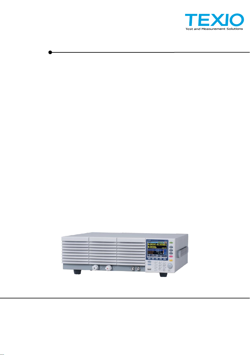
LSG-175
LSG-350
LSG-1050
LSG-2100S
LSG SERIES
INSTRUCTION MANUAL
ELECTRONIC LOAD
LSG SERIES
B71-0408-01

■ About a trademark, a registered trademark
A company name and the brand name mentioned in this instruction
manual are the trademark or the registered trademark of each
company or group in each country and region.
■ About this instruction manual
When copying the part or all of contents of this instruction manual,
seek the copyright holder.
In addition, the specifications of the product and the contents of this
instruction manual are subject to change without notice for
improvement. Please check to our website for the latest version.
■ About Version of LSG Series
This manual will correspond to the Ver 1.27 the firmware of LSG series.

CONTENTS
USING THE PRODUCT SAFELY ························································ Ⅰ-Ⅳ
1. GETTING STARTED ............................................................... 1
1-1. LSG Series Introduction ...................................................... 1
1-1-1. Model Line Up ............................................................................... 1
1-1-2. Main Features ............................................................................... 1
1-2. Accessories ........................................................................ 2
1-2-1. Accessories................................................................................... 2
1-2-2. Package Contents ........................................................................ 3
1-3. Appearance ......................................................................... 4
1-3-1. LSG Series Front Panel ................................................................ 4
1-3-2. Rear Panel .................................................................................... 7
1-3-3. Display .......................................................................................... 9
1-4. First Time Use Instructions ................................................ 10
1-4-1. Rack Mount Kits .......................................................................... 10
1-4-2. Power Up and Self Test .............................................................. 12
1-4-3. Load Default Settings ................................................................. 12
1-4-4. Setting the Date and Time .......................................................... 13
1-4-5. Load Wiring ................................................................................. 14
1-4-6. Load Wire Connections .............................................................. 16
1-4-7. Using the Front Panel Input Terminals ....................................... 17
1-4-8. Using the Rear Panel Input Terminals ........................................ 18
1-4-9. Using the Terminal Cover(PEL -011) ......................................... 18
1-4-10. Using the Terminal Cover (PEL -013) ...................................... 20
1-4-11. Remote Sense .......................................................................... 21
1-4-12. Firmware Update ...................................................................... 22
1-4-13. Conventions .............................................................................. 23
1-4-14. Help Menu................................................................................. 27
2. OPERATION ........................................................................ 28
2-1. Basic Operation ................................................................ 28
2-1-1. CC Mode ..................................................................................... 28
2-1-2. CR Mode ..................................................................................... 29
2-1-3. CR Units ...................................................................................... 30
2-1-4. CV Mode ..................................................................................... 31
2-1-5. CP Mode ..................................................................................... 32
2-1-6. +CV Mode ................................................................................... 33
2-1-7. Turning on the Load .................................................................... 34
2-1-8. Shorting the Load ....................................................................... 34
2-1-9. Safety Short ................................................................................ 35

2-1-10. Short Key Configuration ............................................................ 36
2-1-11. Short Function Enable/Disable ................................................. 36
2-1-12. Locking the Front Panel Controls ............................................. 36
2-2. Basic Configuration ........................................................... 37
2-2-1. Select the Switching Function..................................................... 37
2-2-2. Select the Display Units for Dynamic Mode Levels .................... 39
2-2-3. Select the Switching Time Configuration for Dynamic Mode ..... 40
2-2-4. Slew Rate.................................................................................... 40
2-2-5. CV Mode Response Speed ........................................................ 41
2-2-6. CC,CR and CP Mode Response Speed ..................................... 42
2-3. Advanced Configuration Settings ....................................... 42
2-3-1. Soft Start Setting ......................................................................... 42
2-3-2. Von Voltage Settings .................................................................. 43
2-3-2-1. Von Voltage Level ................................................................... 43
2-3-2-2. Von Voltage Latch ................................................................... 43
2-3-2-3. Von Voltage Delay ................................................................... 44
2-3-3. Timer Functions .......................................................................... 44
2-3-3-1. Count Time .............................................................................. 44
2-3-3-2. Cut Off Time ............................................................................ 45
2-3-4. Auto Load Configuration ............................................................. 45
2-3-5. Load Off (Mode) and Load Off (Range) ...................................... 46
2-4. Step Resolution Configuration ........................................... 46
2-4-1. Cursor Mode Configuration......................................................... 46
2-4-2. Step Mode Configuration ............................................................ 47
2-5. Protection Settings ............................................................ 48
2-5-1. OCP ............................................................................................ 48
2-5-2. OPP ............................................................................................ 49
2-5-3. UVP ............................................................................................. 50
2-5-4. UVP Ring Time ........................................................................... 50
2-5-5. OVP ............................................................................................ 51
2-5-6. UnReg ......................................................................................... 51
2-5-7. Para ............................................................................................ 52
2-5-8. RVP ............................................................................................. 52
2-6. System Settings ................................................................ 53
2-6-1. Sound Settings ........................................................................... 53
2-6-1-1. Speaker Settings ..................................................................... 53
2-6-1-2. Alarm Tone Settings ................................................................ 53
2-6-2. Contrast and Brightness ............................................................. 54
2-6-3. Control Settings .......................................................................... 54
2-6-4. Language Settings ...................................................................... 54
2-6-5. Input/Output Trigger Settings...................................................... 54
2-6-5-1. Trigger In Delay ....................................................................... 54

2-6-5-2. Trigger Out Width .................................................................... 55
2-7. Go-NoGo .......................................................................... 55
2-7-1. Setting the Go-NoGo Limits ........................................................ 55
2-7-2. Running a Go-NoGo Test ........................................................... 56
2-8. Save Recall ...................................................................... 57
2-8-1. File Structure............................................................................... 57
2-8-2. File Types ................................................................................... 58
2-8-3. Saving Files to Internal Memory ................................................. 58
2-8-4. Saving Files to USB Memory ...................................................... 59
2-8-5. Recalling Files from Internal Memory ......................................... 61
2-8-6. Recalling Files from USB Memory .............................................. 62
2-8-7. Recall Memory Safety Setting .................................................... 63
2-8-8. File Utility .................................................................................... 63
2-8-9. Preset .......................................................................................... 64
2-8-9-1. Quick Preset Save ................................................................... 64
2-8-9-2. Quick Preset Recall ................................................................. 65
2-8-10. Default Settings ........................................................................ 65
2-8-10-1. Factory Default Settings ........................................................ 65
2-8-10-2. User’s Default Setting ............................................................ 65
3. Function MENU .................................................................... 66
3-1. Function Menu Overview ................................................... 66
3-1-1. Select a Function ........................................................................ 66
3-1-2. Turning on the Load with the Selected Function ........................ 67
3-1-3. Complete Ring Time ................................................................... 67
3-1-4. NSEQ Timer................................................................................ 68
3-2. Program ............................................................................ 69
3-2-1. Program Overview ...................................................................... 69
3-2-2. Create a Program ....................................................................... 70
3-2-3. Create a Program Chain ............................................................. 73
3-2-4. Running a Program or Chain ...................................................... 74
3-3. Sequence ......................................................................... 75
3-3-1. Normal Sequence Overview ....................................................... 75
3-3-2. Timing Edit Configuration ........................................................... 78
3-3-3. Data Edit Configuration ............................................................... 79
3-3-4. Running a Normal Sequence...................................................... 80
3-3-5. Fast Sequence Overview ............................................................ 81
3-3-6. Timing Edit Configuration ........................................................... 84
3-3-7. Data Edit Configuration ............................................................... 85
3-3-8. Running a Fast Sequence .......................................................... 87
3-4. OCP TestAutomation ......................................................... 87
3-5. OPP Test Automation ........................................................ 92
3-6. BATT Test Automation ....................................................... 97

4. EXTERNAL CONTROL ........................................................103
4-1. Analog Control .................................................................103
4-1-1. J1 Connector Overview ............................................................ 103
4-1-2. External Voltage Control - Overview ........................................ 104
4-1-3. External Voltage Control – Operation ....................................... 104
4-1-4. External Resistance Control - Overview ................................... 106
4-1-5. External Resistance Control – Operation ................................. 107
4-1-6. Turning the Load On using External Control ............................ 109
4-1-7. Load On/Off Status ................................................................... 110
4-1-8. External Control of the Range .................................................. 110
4-1-9. I Range Status .......................................................................... 111
4-1-10. External Trigger Signal ........................................................... 111
4-1-11. External Control of the Alarm ................................................. 112
4-1-12. Alarm Status ........................................................................... 112
4-1-13. Short Control ........................................................................... 112
4-1-14. Monitor Signal Output ............................................................. 113
4-1-14-1. Trigger Signal Output .......................................................... 113
4-1-14-2. Current Monitor Output ........................................................ 114
4-2. Parallel Operation ............................................................ 115
4-2-1. Capacity .................................................................................... 115
4-2-2. Connection ................................................................................ 115
4-2-3. Configuration ............................................................................ 116
4-2-4. Turning the Load On ................................................................. 118
4-2-5. Disable Parallel Mode ............................................................... 118
5. REMOTE CONTROL ........................................................... 119
5-1. Interface Configuration ..................................................... 119
5-1-1. Configure to USB Remote Interface ......................................... 119
5-1-2. Configure GP-IB Interface ........................................................ 119
5-1-3. Configure RS-232C .................................................................. 120
5-1-4. RS-232C/USB Remote Control Function Check ...................... 120
5-1-5. Using Realterm to Establish a Remote Connection ................. 121
5-1-6. GP-IB Function Check .............................................................. 123
6. FAQ ....................................................................................125
7. APPENDIX ..........................................................................126
7-1. Replacing the Dust Filter ..................................................126
7-2. GP-IB Installation .............................................................126
7-3. LSG Series Default Settings .............................................127
7-4. Frame Control Connector Contacts ...................................129
7-5. Operating Mode Description .............................................133
7-5-1. CC Mode ................................................................................... 133
7-5-2. CR Mode ................................................................................... 134
7-5-3. CP Mode ................................................................................... 135

7-5-4. CV Mode ................................................................................... 136
7-6. Operating Area .................................................................137
7-7. LSG Series Specifications ................................................140
7-7-1. Rating ........................................................................................ 140
7-7-2. CC Mode ................................................................................... 140
7-7-3. Rating (Booster / Slave) ............................................................ 141
7-7-4. CR Mode ................................................................................... 142
7-7-5. CV Mode ................................................................................... 142
7-7-6. CP Mode ................................................................................... 143
7-7-7. Slew Rate.................................................................................. 143
7-7-8. Meter ......................................................................................... 144
7-7-9. Dynamic Mode .......................................................................... 145
7-7-10. Soft Start ................................................................................. 147
7-7-11. Remote Sensing ..................................................................... 147
7-7-12. Protection Function ................................................................. 147
7-7-13. Sequence ................................................................................ 148
7-7-14. Other ....................................................................................... 149
7-7-15. Analog External Control .......................................................... 149
7-7-16. Front Panel BNC Connector ................................................... 150
7-7-17. General ................................................................................... 151
7-8. LSG Series Dimensions ....................................................152
7-8-1. LSG-175, LSG-350 ................................................................... 152
7-8-2. LSG-1050.................................................................................. 153
7-8-3. LSG-2100S ............................................................................... 153

USING THE PRODUCT SAFELY
<Pictorial indication>
Some part of this product or the instruction manual
may show
This pictorial indication. In this case, if the product is
incorrectly used in that part, a serious danger may be
brought about on the user's body or the product.
To use the part with this pictorial indication, be sure to
refer to this instruction manual.
<Warning character
Indication>
WARNING
CAUTION
If you use the product, ignoring this indication, you
may get killed or seriously injured. This indication
shows that the warning item to avoid the danger is
provided.
If you incorrectly use the product, ignoring this
indication, you may get slightly injured or the product
may be damaged. This indication shows that the
caution item to avoid the danger is provided.
■ Preface
To use the product safely, read this instruction manual to the end.
Before using this product, understand how to correctly use it.
If you read this manual but you do not understand how to use it, ask
us or your local dealer. After you read this manual, save it so that you
can read it anytime as required.
■ Notes on reading this instruction manual
◆ The contents of this instruction manual include technical terms in part
of their explanation. If you do not understand those terms, do not
hesitate to ask us or your local dealer.
■ Pictorial indication and warning character indication
This instruction manual and product show the warning and caution
items required to safely use the product. The following pictorial
indication and warning character indication are provided.
I

USING THE PRODUCT SAFELY
WARNING
■ Do not remove the product's covers and panels
Never remove the product's covers and panels for any purpose.
Otherwise, the user's electric shock or a fire may be incurred.
■ Warning on using the product
The warning items given below are to avoid danger to the user's body
and life and avoid the damage and deterioration of the product.
Use the product, observing the following warning and caution items.
■ Warning items on power supply
● Power supply voltage
As the rated power supply voltage of the product, the range from
100 to 240 VAC can be used without being switched.
● Power cord
Important: The attached power cord set can be used for this
device only.
● Protection fuse
If an input protection fuse is blown, the product does not operate.
When the fuse is blown, the user can replace it. However, replace it
correctly, observing the warning and caution items that are provided in
the section of the instruction manual where the fuse replacement is
explained. If the fuse is incorrectly replaced, a fire may occur.
● Changing the power supply voltage
The rated power supply voltage cannot be changed. Use the
product only at the rated power supply voltage indicated on the
product. Otherwise, a fire may occur. The product's rated power
supply voltage is from 100 to 240 VAC. Use the product in this
range. (For use at a voltage higher than 125 VAC, Please
confirm the voltage ratings of the power cord.)
■ Warning item on grounding
The product has the GND terminal on the panel surface to protect the
user from electric shock and protect the product. Be sure to ground
the product to safely use it.
II

USING THE PRODUCT SAFELY
WARNING
■ Warning item on installation environment
● Operating temperature
Use the product within the operating temperature indicated in the
rating column. If the product is used with the vents of the product
blocked or in high ambient temperatures, a fire may occur.
● Operating humidity
Use the product within the operating humidity indicated in the rating
column. Watch out for condensation by a sharp humidity change
such as transfer to a room with a different humidity. Also, do not
operate the product with wet hands. Otherwise, an electric shock
or fire may occur.
● Use in a gas
Use in and around a place where an inflammable or explosive gas
or steam is generated or stored may result in an explosion and fire.
Do not operate the product in such an environment.
Also, use in and around a place where a corrosive gas is
generated or spreading causes a serious damage to the product.
Do not use the product in such an environment.
● Do not let foreign matter in
Do not insert metal and flammable materials into the product
from its vent and spill water on it. Otherwise, an electric
shock and fire may occur.
■ Warning item on abnormality while in use
If smoke or fire is generated from the product while in use, stop using
the product, turn off the switch, and remove the power cord plug from
the outlet. After confirming that no other devices catch fire, call the
company or each sales office.
■ Front Panel
Please do not lift up the product, while touching the front grille.
III

USING THE PRODUCT SAFELY
CAUTION
■ Input/output terminal
Maximum input to the input terminals is specified to prevent the product
from being damaged. Do not supply input, exceeding the specifications
that are indicated in the "Rating" or "Caution on use" column in the
instruction manual of the product. Otherwise, a product failure is caused.
Also, do not supply power to the output terminals from the outside.
Otherwise, a product failure is caused.
■ When the product is left unused for a long time
Be sure to remove the power plug from the outlet.
(Calibration)
Although the performance and specifications of the product are
checked under strict quality control during shipment from the factory,
they may aging rate because of aging rate in its parts. It is
recommended to periodically calibrate the product so that it is used
with its performance and specifications stable. For consultation
about the product calibration, call the dealer or the company or each
sales office where you bought the product.
(Daily maintenance)
When you clean off the dirt of the product covers, panels, and knobs,
avoid solvents such as thinner and benzene. Otherwise, paint may
peel off or the resin surface may be affected.
To wipe off the covers, panels, and knobs, use a soft cloth with
neutral detergent in it. During cleaning, be careful that water,
detergents, and other foreign matters do not get into the product.
If a liquid or metal gets into the product, an electric shock and fire are
caused. During cleaning, remove the power cord plug from the outlet.
Use the product correctly and safely, observing the above warning and
caution items. Because the instruction manual indicates caution items
even in individual items, observe those caution items to correctly use the
product.
If you have questions or comments about the content of the instruction
manual, ask us or E-Mail us.
IV
Model
Operating Voltage (DC)
Current
Power
LSG-175
1.5V~150V
35A
175W
LSG-350
1.5V~150V
70A
350W
LSG-1050
1.5V~150V
210A
1050W
Booster Model
Operating Voltage (DC)
Current
Power
LSG-2100S
1.5V~150V
420A
2100W
Performance
High slew rates of up to 16A/μS(LSG-1050) for a fast
response speed
High capacity when used in parallel:
5250W, 1050A (LSG-1050 x 5)/
9450W, 1890A (LSG-1050 + LSG-2100S x 4)
High resolution – 16 bit
1. GETTING STARTED
This chapter provides a brief overview of the LSG Series, the
package contents, instructions for first time use and an
introduction to the front panel, rear panel and GUI.
1-1. LSG Series Introduction
The LSG Series is a family of high performance DC electronic loads
positioned to test a wide range of different power sources. The DC
electronic loads are fully programmable to simulate anything from
basic static loads to complex dynamic loads. With the ability to
operate independently or in parallel, the LSG Series is extremely
robust and capable of molding to any test environment.
Please note that throughout this manual the term “LSG Series” refers
to any one of the models in the series lineup, unless specifically
stated otherwise.
1-1-1. Model Line Up
There are a total of 3 DC electronic load models and 1 booster
pack model.
1-1-2. Main Features
1

Features
7 operating modes:
CC, CV, CR, CP, CC+CV, CR+CV, CP+CV
Independent and parallel operation
Fully programmable with normal and fast sequences
Soft start
Dynamic mode
OCP, OVP and other protection features
Remote sense
Integrated meter
Rack-mountable
Load booster
Interface
USB, RS-232C and GP-IB
External voltage or resistance control
Front panel trigger out BNC
Front panel current monitoring BNC
Analog external control
Standard
Accessories
Part number
Description
Accessories
CD-ROM
Instruction manual
Programming manual
USB driver
Region dependent
Power cord
PEL-011
Load input terminal Cover x1
M3 Screw x1
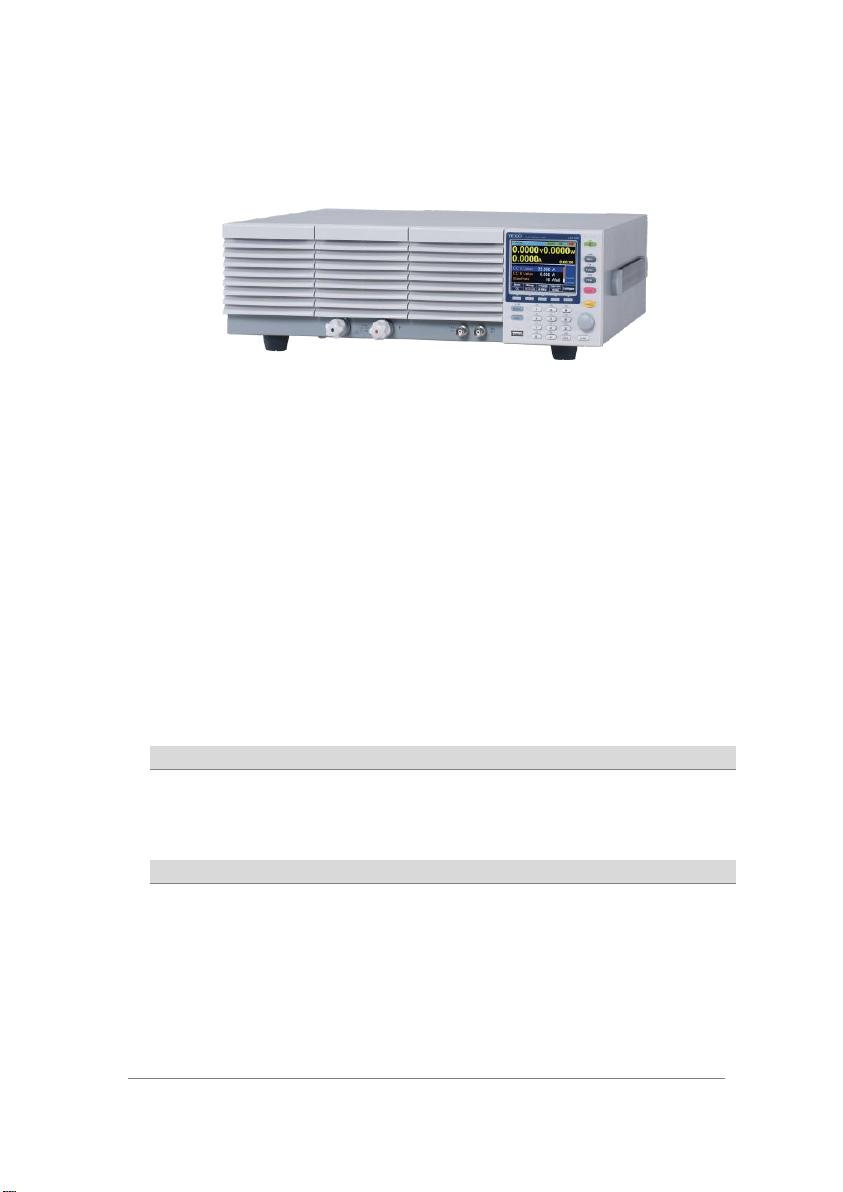
PEL-012
Terminal fittings:
2 sets of bolts/nuts/springs /washers
(type: M8)
M8 x 20
Spring washer
Flat washer
M8 nut
PEL-013
(LSG-2100S only)
Flexible terminal cover:
Velcro
fasteners x4
Rubber
sheeting x2
1-2. Accessories 1-2-1. Accessories
2
PEL-014
Frame control connector with strain
relief x2.
Strain relief
Connector
61SF-062104N1
Front terminal washers. (M6) x2
GTL-255
(LSG-2100S only)
Frame Link Cable
Optional
Accessories
Part number
Description
GRA-413
Rack mount bracket for booster
LSG-2100S for EIA/JIS
GRA-414-E
Rack mount frame for LSG-175,
LSG-350, LSG-1050 /EIA
GRA-414-J
Rack mount frame for LSG-175,
LSG-350, LSG-1050 /JIS
GTL-248
GP-IB cable, 2.0m
GTL-246
USB cable, Type A - Type B
PEL-010
Dust Filter
PEL-004
GP-IB option
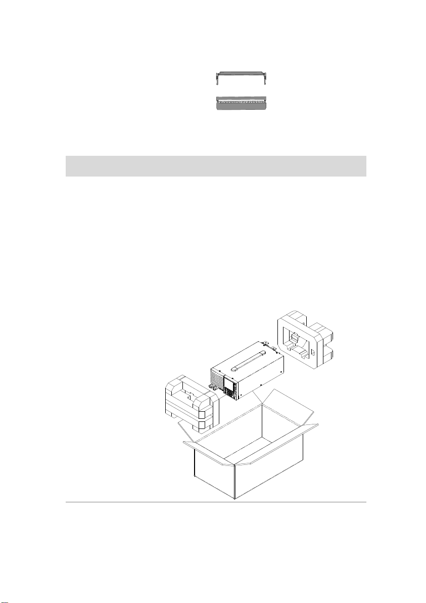
Opening the box
Contents
(single unit)
Main unit
Accessories CD
Terminal fittings
Power cord x1 (region dependent)
1-2-2. Package Contents
Check the contents before using the instrument.
3
I MON OUT TRIG OUT
1.5 - 150V
175W
0 - 35A
P0
P1
P4
P7
CAL.
P2
P5
P8
Lock
P3
P6
P9
Utility
Local
File
0
1
4
7
2
5
8
3
6
9
EnterClear
Shift
Preset
Load
On/
Off
Main
Help
FUNC
Short
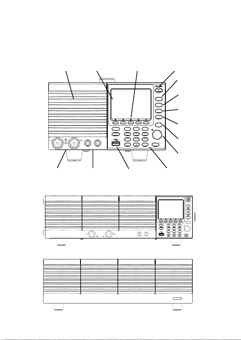
Air inlet LCD Display Power key
FUNC/ File
Help/Utility
Short
Load On/Off
USB Port, Preset
and Shift keys
Number pad, Clear/
Lock and Enter keys
Main/Local
Scroll wheel
Function keys
Input
terminals
I MON OUT,
TRIG OUT
P0
P1
P4
P7
CAL.
P2
P5
P8
Lock
P3
P6
P9
Utility
Local
File
0
1
4
7
2
5
8
3
6
9
EnterClear
Shift
Preset
Load
On/
Off
Main
Help
FUNC
Short
TRIG
OUT
I MON
OUT
1.5 - 150V
1050W
0 - 70A
LINK STBY
1-3. Appearance 1-3-1. LSG Series Front Panel
・LSG-175 / LSG-350
・LSG-1050
・LSG-2100S Booster Pack
4
Air Inlet
(Front grille)
The air inlet has a removable dust filter.
Please do not lift up the product, while touching the front
grille.
LCD display
3.5 inch LCD display
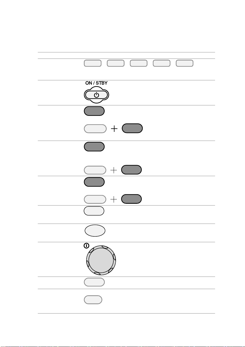
Function keys
The function keys directly correspond to the soft menu
keys at the bottom of the display.
ON/STBY
Turns the unit on or puts the unit into
standby mode. Use the power switch
on the rear panel to turn the unit off.
Main/Local
Main
Main: Sets the operating mode:
CC, CV, CR, CP mode.
Local
Main
Shift
Local (Shift + Main): Puts the
instrument back into local
mode from remote mode.
FUNC/File
FUNC
FUNC: Sets the program function,
sequence function or other special
functions.
File
FUNC
Shift
File (Shift + FUNC):
Accesses the file system.
Help/Utility
Help
Help: Access the help menu.
Utility
Help
Shift
Utility (Shift + Help): Access
the utility menu.
Short
Short
Pressing the Short key will simulate
shorting the input terminals.
The Short key will be lit when active.
Load on/off
Load
On/
Off
Turns the load on or off.
The Load On/Off key will be lit when
active.
Scroll wheel
Use the scroll wheel to navigate the
menu system.
Pushing the scroll wheel will toggle
between coarse and fine adjustment,
or Select digit.
Enter
Enter
Press the Enter key to select
highlighted menu items.
Clear/Lock
Lock
Clear
Clear: Clears the current parameter
values.
Lock (Shift + Clear): Locks the front
panel keys and selector knob.
5
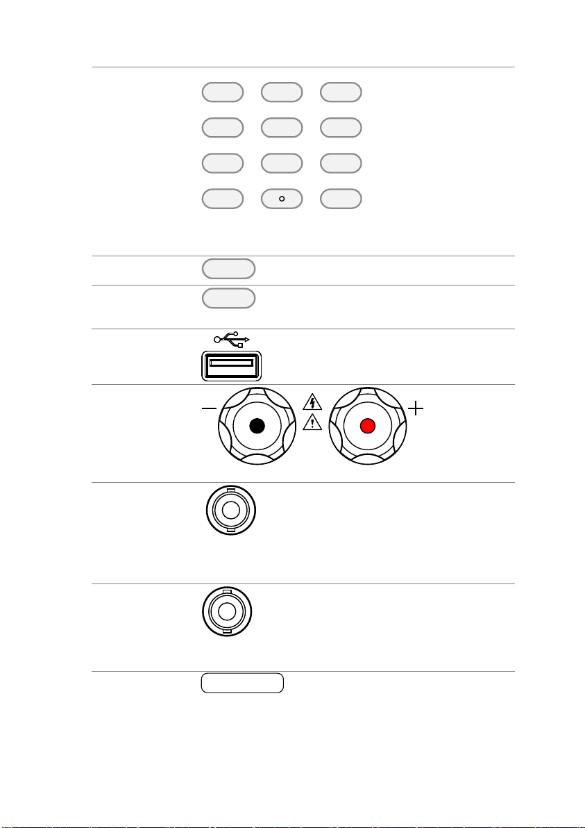
Number pad
P0
P1
P4
P7
CAL.
P2
P5
P8
Lock
P3
P6
P9
0
1
4
7
2
5
8
3
6
9
Clear
Number pad: Used to enter numerical values.
P0~P9 (Preset + Number keys): Loads one of 10 preset
settings.
Shift
Shift
Shift: Used in conjunction with other
keys to select secondary functions.
Preset
Preset
Used in conjunction with the number
pad to save or load preset settings P0
to P9.
USB Port
USB A port. Used for save and recall
functions.
Front panel
input terminals
1.5 - 150V
175W
0 - 35A
Negative terminal.
Positive terminal.
IMON Out
I MON OUT
Current monitor BNC terminal: Output
connector used to monitor the current
by outputting a voltage. An output
voltage of 1V corresponds to the full
scale current for the H and L ranges.
0.1V corresponds to the full scale
current in the M range.
TRIG OUT
TRIG OUT
Trigger out BNC terminal:
Outputs a pulse signal during
sequence or dynamic operation. The
trigger signal has a 4.5V output with a
pulse width of a least 2us and an
impedance of 500Ω.
LINK/STBY
Indicator
(LSG-2100)
LINK STBY
The LINK and STBY indicators
indicate when the booster pack is
properly connected and when the
power has been turned on,
respectively.
6
47 - 63 Hz
90 VA MAX.
AC
100 - 120 VAC
200 - 240 VAC
FRAME CONT
J 1
J 2
SER. NO. LB
RS232C
GPIB
WARNING
TO AVOID ELECTRIC SHOCK THE POWER CORD
DO NOT REMOVE COVERS.
NO OPERATOR SERVICEABLE COMPONENTS INSIDE.
PROTECTIVE GROUNDING CONDUCTOR MUST BE
REFER SERVICING TO QUALIFIED PERSONNEL.
CONNECTED TO GROUND.
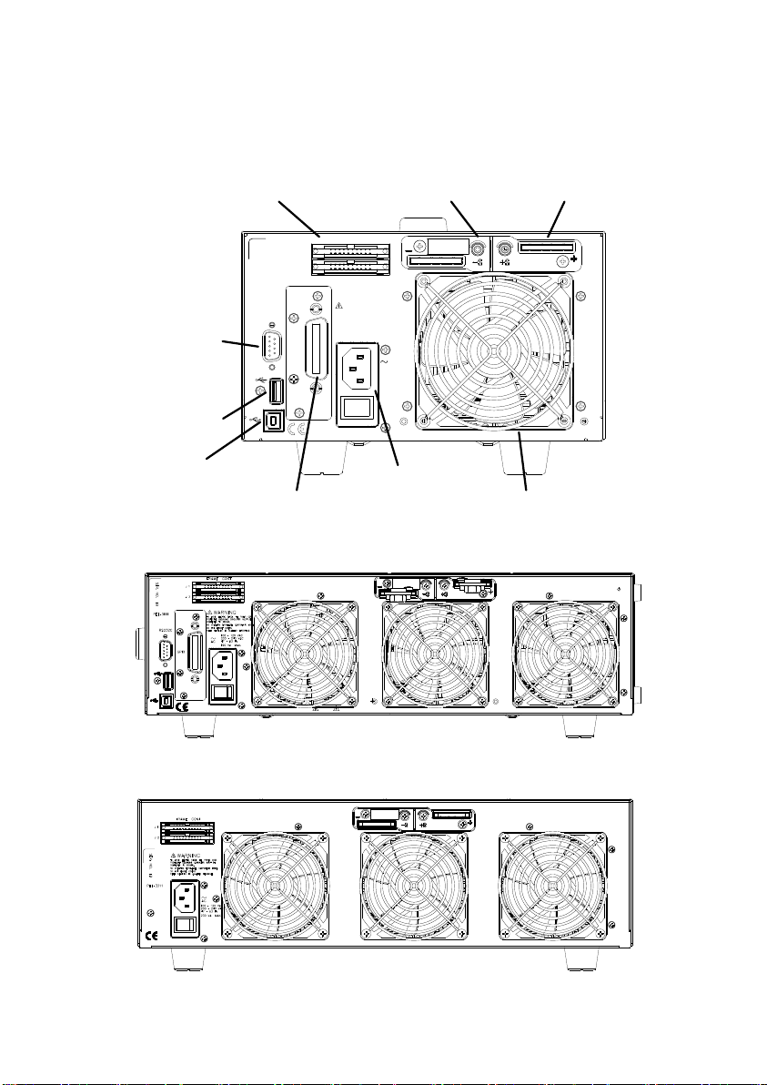
Remote
sense inputs
Frame control
ports, J1, J2
RS-232C
port
USB
port
USB device
port
Exhaust
fan
GP-IB
Power
socket and
switch
Rear panel
inputs
port
P0
P1
P4
P7
CAL.
P2
P5
P8
Lock
P3
P6
P9
Utility
Local
File
0
1
4
7
2
5
8
3
6
9
EnterClear
Shift
Preset
Load
On/
Off
Main
Help
FUNC
Short
TRIG
OUT
I MON
OUT
1.5 - 150V
1050W
0 - 70A
1-3-2. Rear Panel
・LSG-175 / LSG-350
LSG-1050
・
・LSG-2100S Booster Pack
7
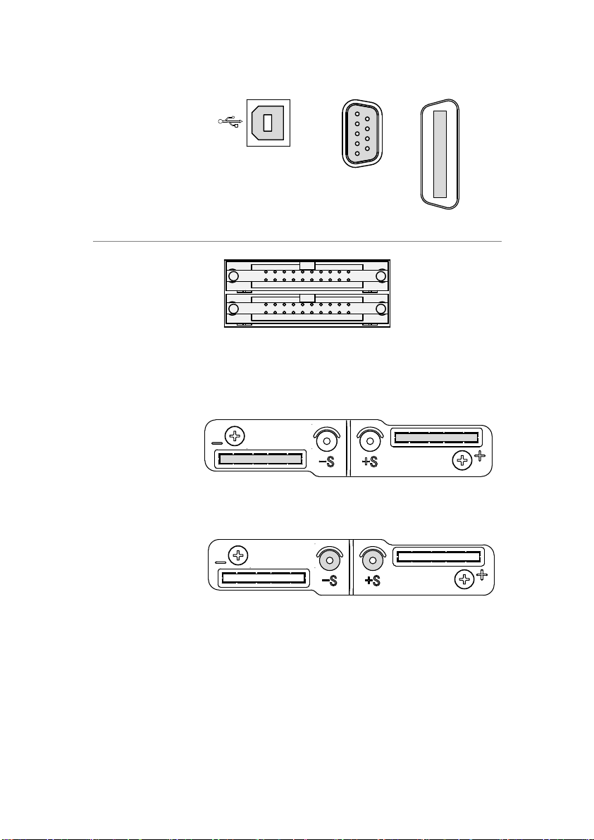
RS-232C Port
GP-IB
USB B
The USB B, RS-232C and GP-IB port are used for
remote control.
USB B port
RS-232C 9 pin
DSUB port.
GP-IB 24 pin
female.
Frame control
ports, J1, J2
FRAME CONT
J 1
J 2
J1: The J1 connector is assigned to external control.
J2: The J2 connector is used for parallel operation
control.
Exhaust fan
The exhaust fan is used to expel the heat from the
unit. Please ensure there is at least 20cm distance
between any object and the fan.
Rear Panel
Input
terminals
Rear Panel Input Terminals. Electrically connected
to the front panel input terminals. Accepts M8 bolts
or M4/M3 sized screws. See page 18 for connection
details.
Remote
Sensing
Terminals
Sensing terminals for remote sense. See page 21.
Accepts M3 sized screws.
8
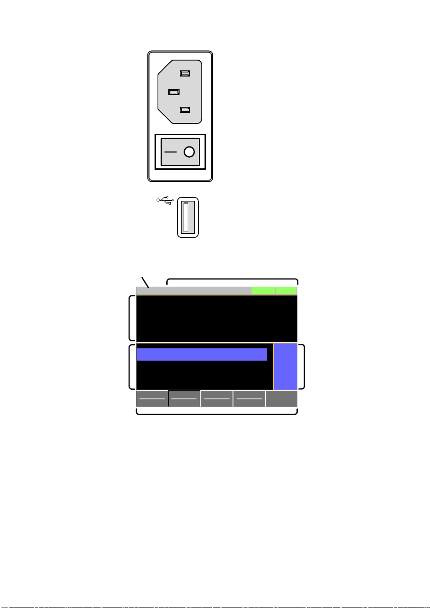
Power Socket
Power Socket:
100~120V, 200~240V
47~63Hz.
Power Switch
Turns the unit on/off.
USB A
USB A Slave port. USB 1.1/2.0
ModeCVI Range
H 35A
V Range
L 15V
Function
Static
Configure
0.000
V
0.000
A
0.00
w
SlewRate 2500.00
CC B Value 0.000
CC A Value 0.000
LOADRS232
A Value
Fine
31/Oct/2013
mA/us
A
A
Date
Setting
area
Operation
status
panel
Measurement
area
Mainframe status panel
Softkeys
Setting area
The setting area is used to display and edit the
settings for the current mode / function.
Measurement area
Displays the voltage, current and power values.
Date
Displays the date
Mainframe status
panel
The mainframe status panel displays the status of
the load, remote control and short function.
When an icon is green it indicates that the function
is off. When the icon is orange, the function is on.
Operation Status
Panel
This status panel is used to display the status of
the current mode.
Soft-keys
The soft-key menus are used to select different
functions or parameters.
1-3-3. Display
9
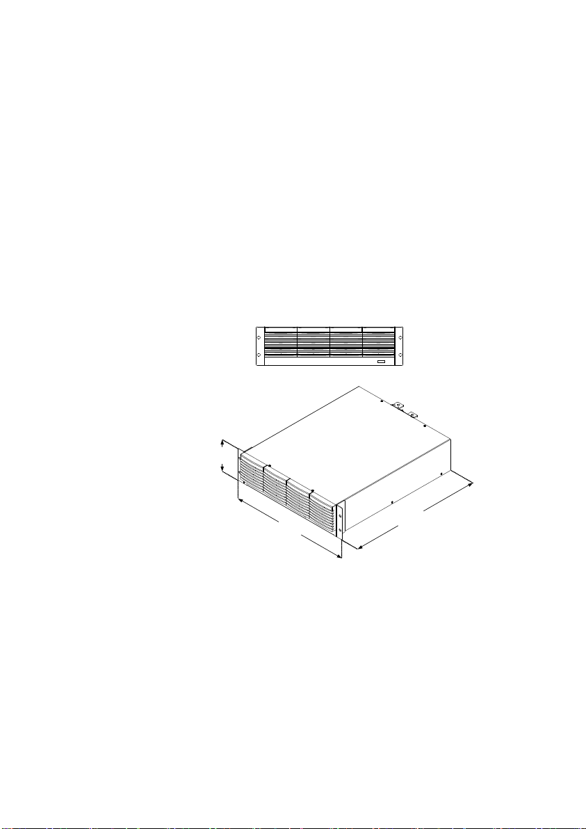
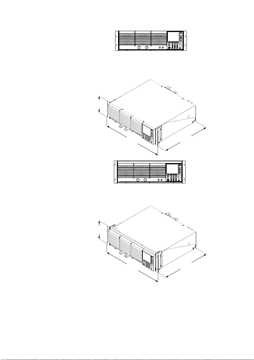
Description
The LSG Series has a number of rack mount
options for installation. The GRA-413 rack
mounts are suitable for the LSG-2100S booster
pack. The GRA-414 rack mounts are capable of
holding 1x LSG-1050 or 2x LSG-175/350 units.
For installation details, please see the GRA-413
and GRA-414 Rack Mount Assembly Manual.
Please see your distributor for which rack mount
is suitable for your application.
GRA-413
(For LSG-2100)
128
(149)
4
8
2
.
6
5
3
2
.
5
1-4. First Time Use Instructions
Use the procedures below when first using the LSG Series to install
the rack mount kit, power up the instrument, set the internal clock,
restore the factory default settings and check the firmware version.
Lastly, the Conventions section will introduce you to the basic
operating conventions used throughout the user manual.
1-4-1. Rack Mount Kits
10
GRA-414-E
(EIA standard)
132
382
.
5
477
.
6
GRA-414-J
(JIS standard)
149
382
.
5
477
.
6
11

Steps
1. Insert the AC power cord into the power socket.
2. Turn the external power
switch on.
(O → —)
3. If the unit doesn’t turn on, press the On/Standby
key for a second.
The ON/STBY key will go from standby (red) to
on (green).
4. The unit will show the splash screen and then
load the settings from when the unit was last
powered down.
5. To turn off the power, press the ON/STBY key
again for a second.
Note
If the LSG Series fails to start up properly or
does not turn on, please see your local
distributor.
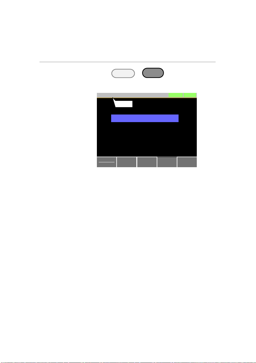
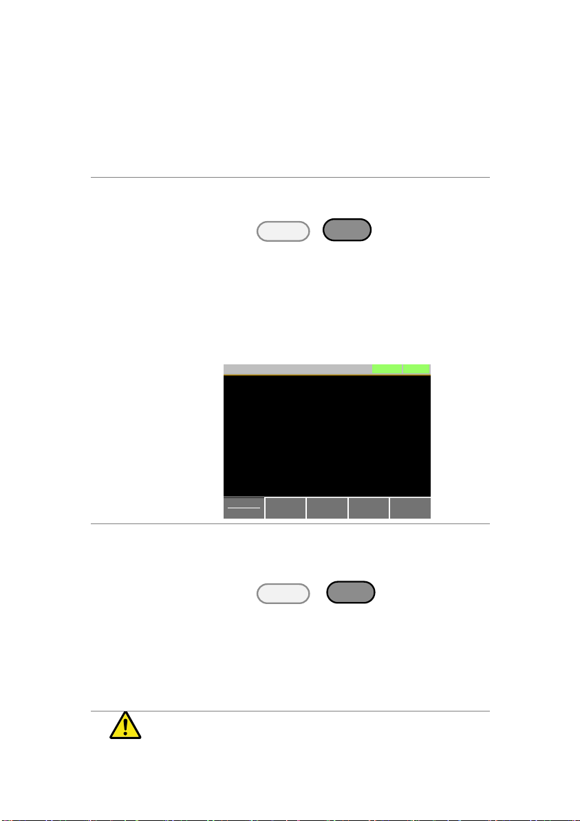
Description
When first using the LSG Series, recall the
factory default settings to ensure the unit is in a
known state. See page 127 for a list of the
default settings.
Operation
1. Press
Shift
+
File
FUNC
.
Select Media/Default[F1].
Select Factory Default[F2].
Media
Default
Factory
Default
Save Recall
LOADRS232
A Value
Fine
31/Oct/2013
Load Default Setup
CC
35A
15V
Static
Recall The Default Settings!
Pressing F2 Again will
Warning!!!
1-4-2. Power Up and Self Test
1-4-3. Load Default Settings
12
Description
The date and time settings are used to timestamp files when saving files.
The date and time is shown on top of the
display.
Operation
1. Press
Shift
+
Utility
Help
> Time Set[F4] to
set the date and time.
Settings:
Month, Day, Year, Hour, Minute
System
Info
Load Interface Time Set
LOADRS232
31/Oct/2013
Other
9
Hour 0
Year 2012
Minute
Day
Month
9
3
Date/Time
Date
1-4-4. Setting the Date and Time
13

Wire Gauge
considerations
Before connecting the unit to a power source,
the wire gauge must be taken into account.
Load wires must be large enough to resist
overheating when a short-circuit condition
occurs as well as to maintain a good regulation.
The size, polarity and length of a wire are all
factors in determining if a wire will withstand
short circuiting.
Wires that are selected must be large enough to
withstand a short circuit and limit voltage drops
to no more than 2V per wire. Use the table
below to help make a suitable selection.
AWG
Gauge
Conduct or
Diameter
mm
Ohms per
km
Max amps for
chassis wiring
0000
11.684
0.16072
380
000
10.4038
0.2027
328
00
9.26592
0.25551
283
0 8.25246
0.32242
245
1 7.34822
0.40639
211
2 6.54304
0.51266
181
3 5.82676
0.64616
158
4 5.18922
0.81508
135
5 4.62026
1.02762
118
6 4.1148
1.29593
101
7 3.66522
1.6341
89
8 3.2639
2.0605
73
9 2.90576
2.59809
64
10
2.58826
3.27639
55
11
2.30378
4.1328
47
12
2.05232
5.20864
41
13
1.8288
6.56984
35
14
1.62814
8.282
32
Load Line
Inductance
Considerations
When using the LSG Series load generator,
voltage drop and voltage generated due to load
line inductance and current change must be
taken into account. Extreme changes in voltage
may exceed the minimum or maximum voltage
limits. Exceeding the maximum voltage limit
may damage the LSG Series.
To determine the voltage generated, the
following equation can be used.
E = L x (∆ I / ∆ T)
E= voltage generated
L=load line inductance
1-4-5. Load Wiring
14
∆ I= change of current (A)
∆ T= time (us)
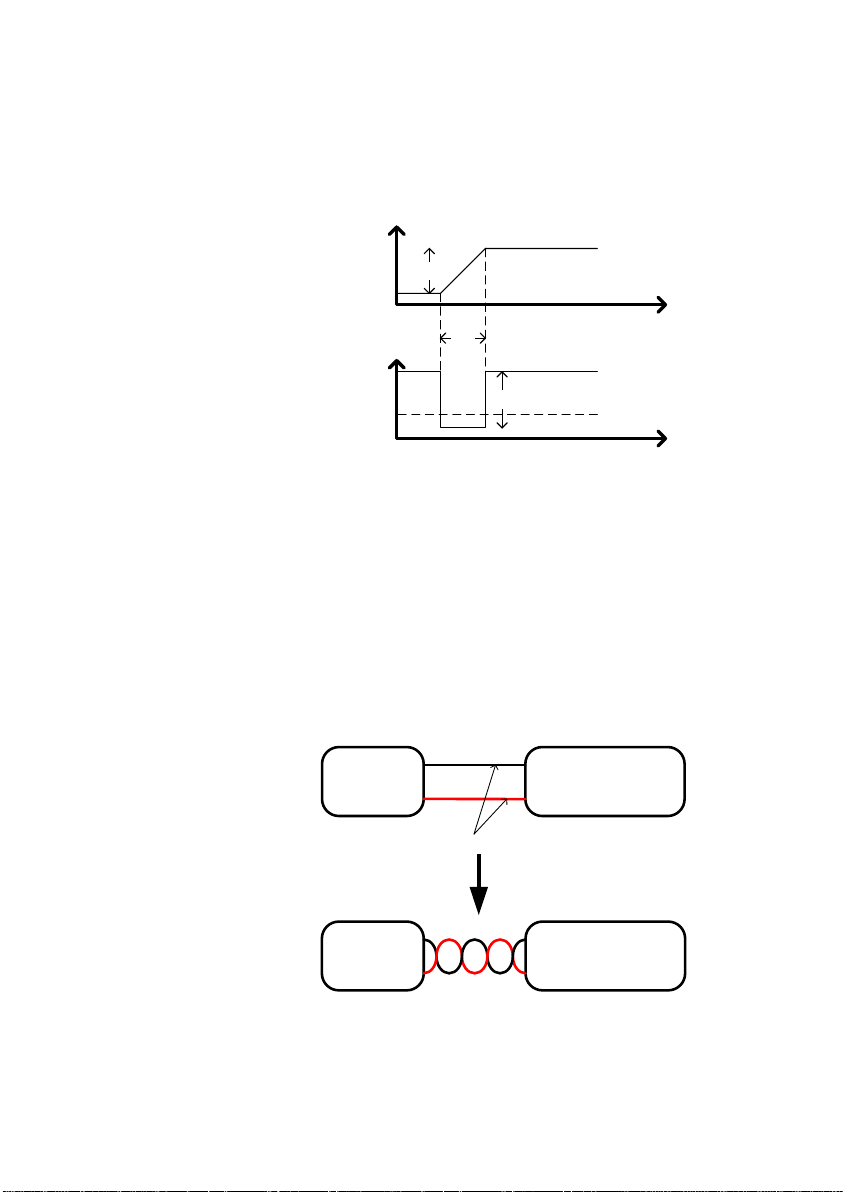
Load line inductance (L) can be approximated
as 1uH per 1 meter of wire. (∆ I / ∆ T) is the slew
rate in A/us.
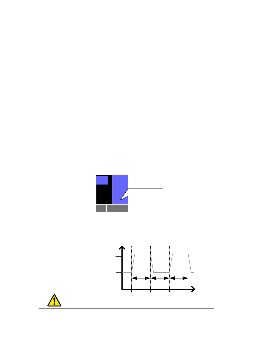
Current
Voltage
time
time
∆I
∆T
E
Min. V
The diagram above shows how changes in
current can affect voltage.
Limiting Load
line inductance
Load line inductance can be reduced in two
ways.
1. Ensure load wires are as short as possible and
twist the positive and negative load wires
together.
2. Current change can be limited by limiting the
slew rate or response speed when switching in
CR and CC mode.
“Twisted pair” will be shown on any connection
diagram where the load wires should be twisted
together.
DUT
-
+
Electronic
Load
+
-
Twisted
pair
DUT
-
+
Electronic
Load
+
-
15
Description
The LSG Series has input terminals on both the
front and rear panels.
Follow the procedures below for all load
connections. Please adhere to the following
precautions to ensure your safety and to protect
the unit from damage.
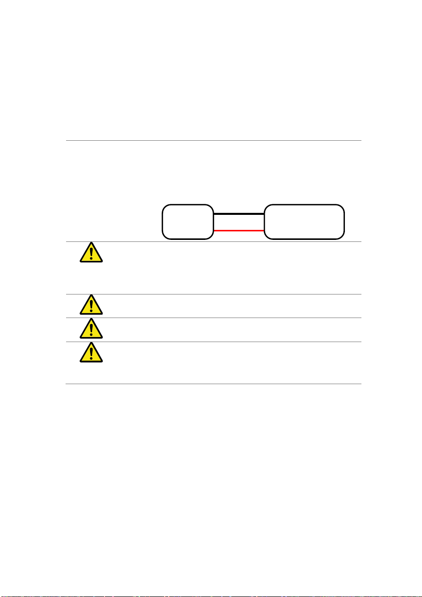
Connection
When connecting the LSG Series to the DUT,
make sure that the polarity of the connection
between the DUT and the unit matches.
Ensure that the maximum input voltage is not
exceeded. The maximum input voltage is 150
volts.
DUT
-
+
Electronic
Load
+
-
Caution
If the polarity to the input terminals is reversed,
the reverse voltage protection function is tripped.
The reverse voltage protection function is tripped
when reverse voltages greater than -0.3V are
detected.
Warning
Do not touch any of the input terminals when the
unit is on.
Warning
Connecting the input terminals to the wrong
polarity can damage the DUT or the LSG Series.
Warning
The front panel and rear panel input terminals are
physically connected. Any voltage that is input to
one set of terminals will also appear on the other
set of terminals.
1-4-6. Load Wire Connections
16
Description
The front panel input terminals feature polaritydistinct caps and accept M6 sized crimped
terminals.
Caution
The front panel input terminals on the LSG
Series are physically connected to the rear
panel terminals.
Step
1. Turn the power off from the rear panel or put the
unit into standby mode.
2. Turn the power off from the DUT.
3. Connect the load wires to the input terminals:
Connect the positive (+) input terminal on the
load generator to the high potential output of
the DUT.
Connect the negative (-) input terminal to the
low potential output of the DUT.
- potential
+ potentional
Positive
terminal
Negative
terminal
1-4-7. Using the Front Panel Input Terminals
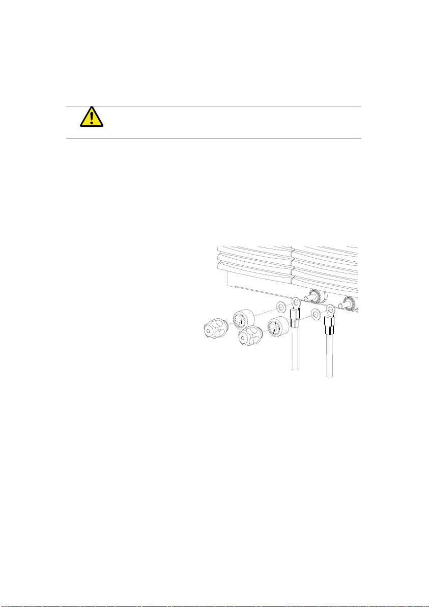
17
Description
The rear panel input terminals accept up to M8sized crimped terminals. The rear terminals
come with a load input terminal cover for safety.
Caution
The front panel input terminals on the LSG
Series are physically connected to the rear
panel terminals.
Steps
1. Turn the power off from the rear panel or put the
unit into standby mode.
2. Turn the power off from the DUT.
3. Connect the load wires to the input terminals:
Connect the positive (+) input terminal on the
load generator to the high potential output of
the DUT.
Connect the negative (-) input terminal to the
low potential output of the DUT.
+ potentinal
- potential
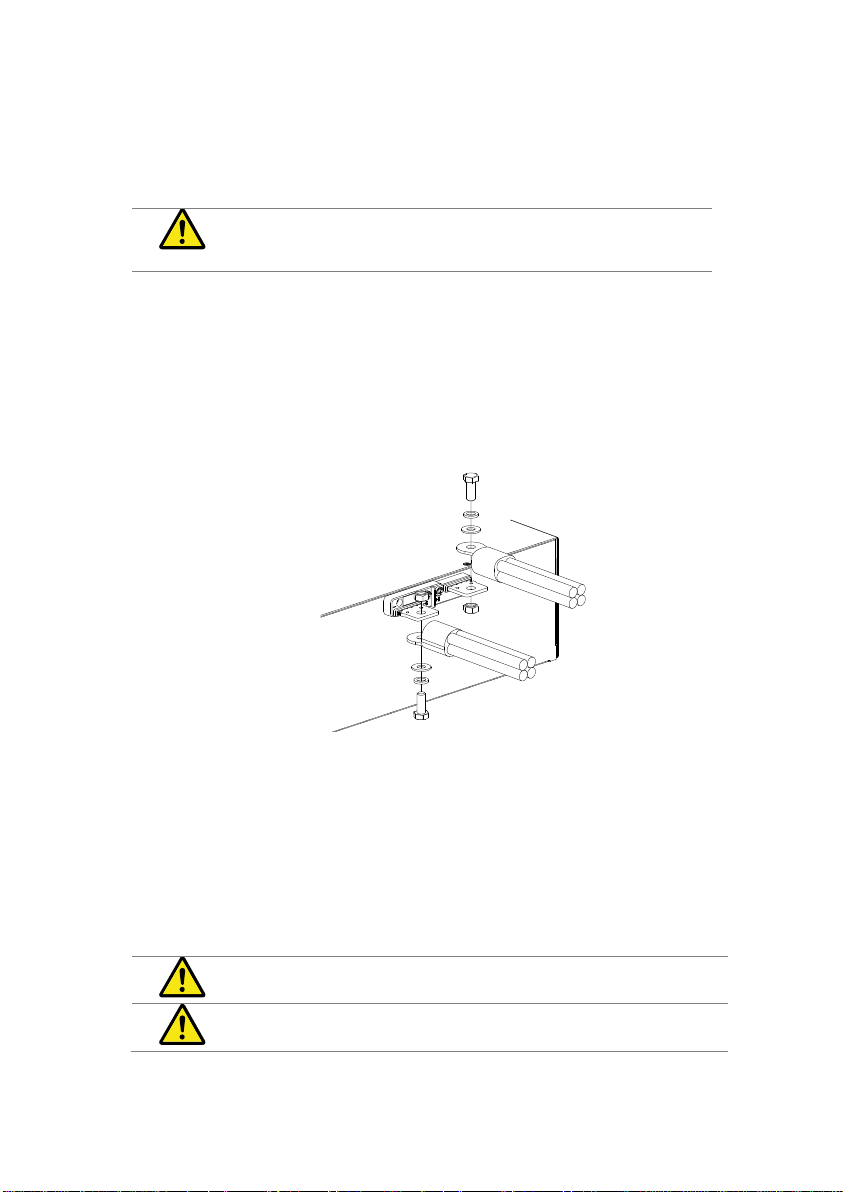
Description
The rear panel terminal cover should be used to
prevent electric shock. The rear panel terminal
covers should always be used when connecting a
load to the rear panel terminals. As the front panel
and rear panel terminals are physically connected,
the terminal cover should also be used as a safety
measure when a DUT is connected to the front
terminals
Caution
Ensure the power is off before making any
connections to the LSG Series.
Note
In the following diagrams, the cable wiring is not
shown for clarity.
1-4-8. Using the Rear Panel Input Terminals
1-4-9. Using the Terminal Cover(PEL -011)
18

1. Remove the screw holding the top cover to the
bottom cover.
1
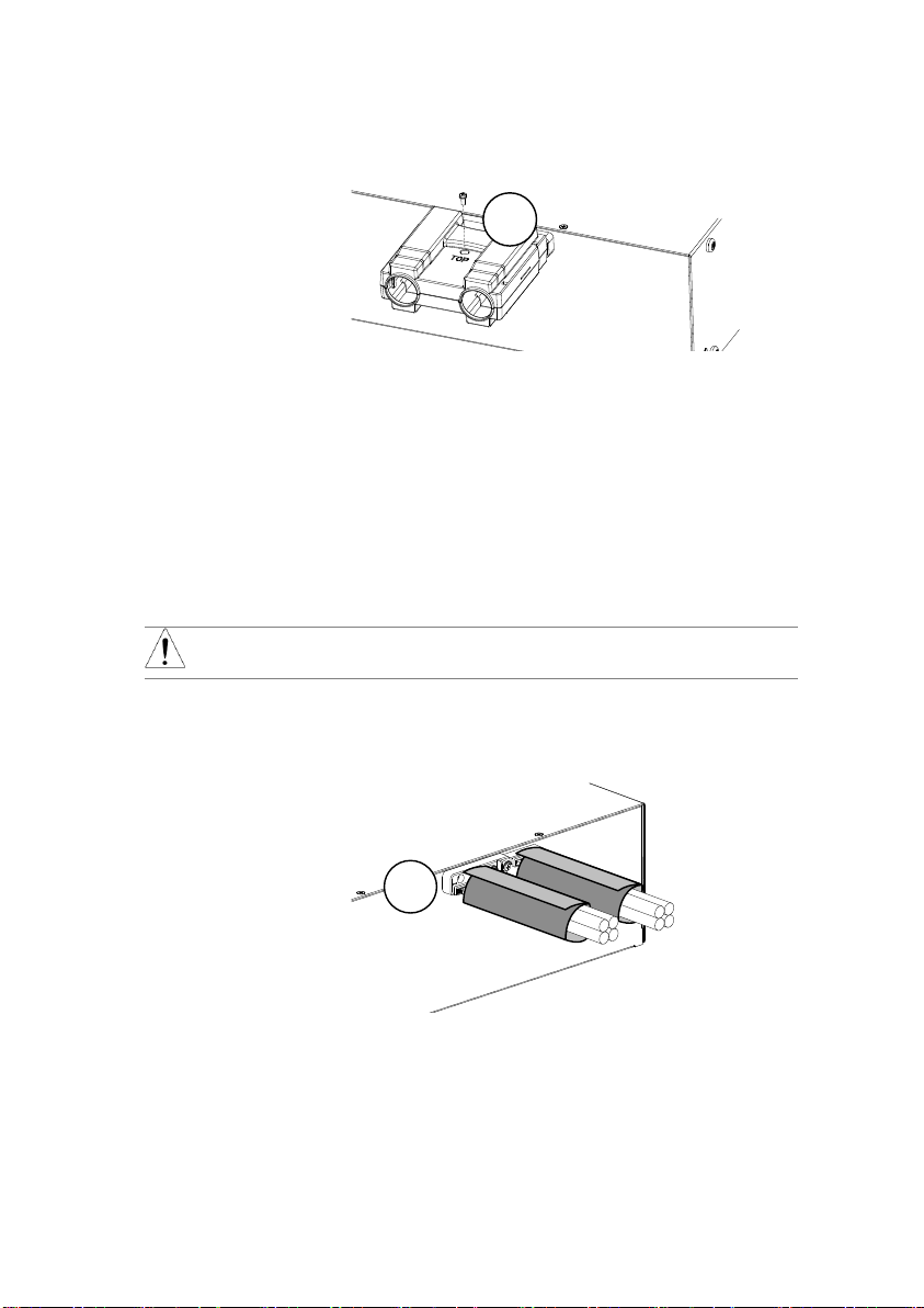
2. Line-up the bottom cover with the notches in the
output terminals.
3. Place the top terminal cover over the bottom
cover.
2
Detail
3
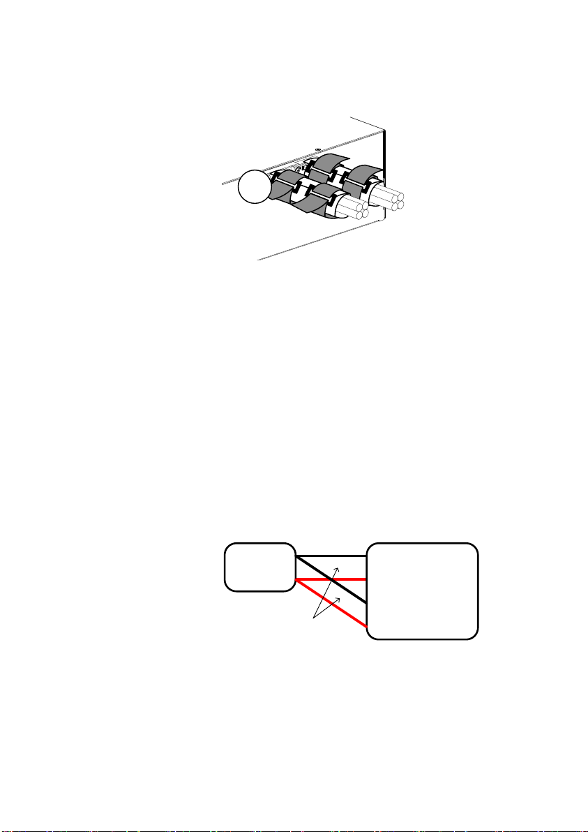
4. Use your thumb to slide the terminal covers shut,
as shown in the diagram below.
4
19
5. When the top and bottom covers are flush,
reinsert the screw that was removed in step 1.
5
Description
The flexible rear panel terminal cover should
be used when the load wiring becomes too
thick to be used with the PEL-011 terminal
cover. This is especially true when using the
load generators in parallel. Like the PEL-013
terminal cover, the PEL-011 is used to
prevent electric shock. The rear panel
terminal covers should always be used when
connecting a load to the rear panel terminals.
Caution
Ensure the power is off before making any
connections to the booster pack.
1. Wrap the insulation sheets around the
terminals and load cables, as shown below.
Make sure the terminals and any exposed
wires are covered by the sheets.
Insulation sheet
1
1-4-10. Using the Terminal Cover (PEL -013)
20
2. Secure the insulation sheets using the
supplied velcro fasteners. 2 fasteners should
be used for each sheet.
Fasteners
2
Description
Remote sense can be used to help compensate
for long cable length. The longer the cable, the
higher the potential resistance and inductance,
therefore a short cable is best. Twisting the
cable can help reduce induced inductance and
using the Vsense terminals compensates the
voltage drop seen across the load leads,
especially leads with higher resistance. This is
useful when used in CV, CR or CP mode.
Steps
1. Turn the power off from the rear panel or put the
unit into standby mode.
2. Turn the power off from the DUT.
3. Connect the sense wires to the sense terminals:
Connect the positive sense (+S) terminal to the
high potential output of the DUT.
Connect the negative sense (-S) terminal to
the low potential output of the DUT.
DUT
-
+
Programable
Electronic
Load
+
-
+S
-S
Twisted
pair
1-4-11. Remote Sense
21
Description
The LSG Series allows the firmware to be
updated by end-users. Before using the LSG
Series, please check the TEXIO TECHNOLOGY
website or ask your local distributor for the latest
firmware.
System version
Before updating the firmware, please check the
firmware version.
Operation
1. Press
Shift
+
Utility
Help
.
2. Select System/Info[F1].
3. The System information is listed on the display.
Model: Model number of the LSG.
Serial Number: Serial number of the LSG.
Firmware Ver: Firmware version of the LSG.
http: Texio website address.
4. To view other system information, press
System[F1] and select Memo.
System
Info
Load Interface Time Set
LOADRS232
31/Oct/2013
Model: LSG-xxxx
http://www.texio.co.jp
Firmware Ver: x.xx.xxx
Serial Number: xxxxxxxx
Other
Update
Firmware
1. Insert a USB drive into the USB port. Ensure the
USB drive has the firmware file located in the
root directory.
2. Press
Shift
+
File
FUNC
.
3. Select USB with the Media[F1] soft-key.
4. Press the File Utility[F5] soft-key.
5. Select the *.UPG upgrade file and press
Select[F1] twice. Once to select the file and
once to confirm.
6. Wait for the update to complete and reset the
power when prompted.
Note
Do not turn the load generator off or remove the
USB memory when the firmware is being read
or upgraded.
1-4-12. Firmware Update
22
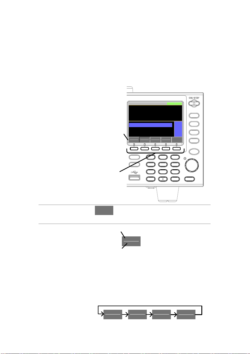
Soft Menu keys
The F1 to F5 function keys at the bottom of the
display correspond directly to the soft-menu keys
on top.
P0
P1
P4
P7
CAL.
P2
P5
P8
Lock
P3
P6
P9
Utility
Local
File
0
1
4
7
2
5
8
3
6
9
EnterClear
Shift
Preset
Load
On/
Off
Main
Help
FUNC
Short
F1 ~ F5
Function keys
Soft-menu
keys
ModeCCI Range
H 35A
V Range
L 15 V
Function
Static
Configure
0.000
V
0.000A
0.00w
SlewRate 2500.00
CC B Value 0.000
CC A Value 0.000
LOADRS232
A Value
Fine
31/Oct/2013
mA/us
A
A
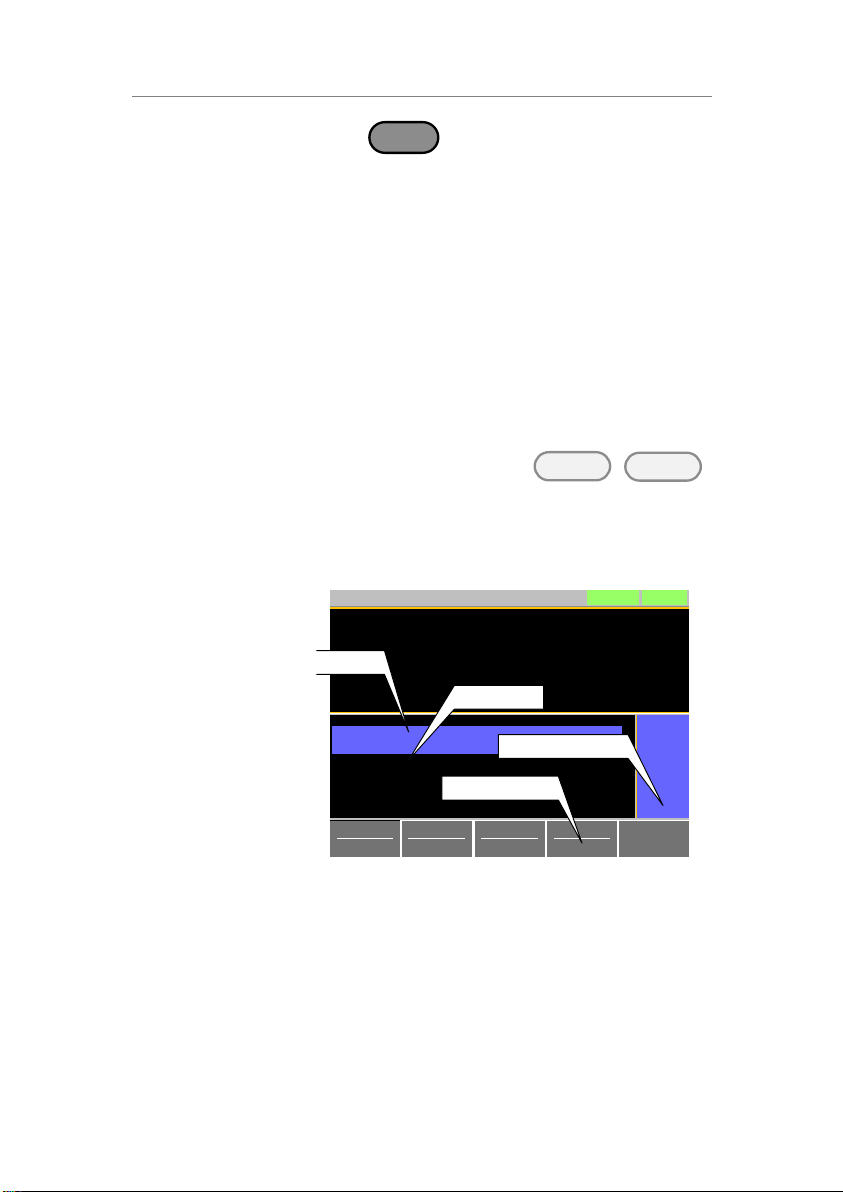
Select Sub
Menu
Configure
Pressing this type of soft-menu key will
enter a submenu.
Toggle
Parameter or
State
Mode
CC
Function/Item
Parameter or State
This type of soft-menu icon has the function
/item on the top of the label and the selected
setting or mode on the bottom of the label.
Repeatedly press the associated function key
(F1~F5) to cycle through each setting. For
example, repeatedly pressing the Mode softmenu key will cycle through the CC, CR, CV
and CP modes.
Mode
CR
Mode
CC
Mode
CV
Mode
CP
1-4-13. Conventions
The following conventions are used throughout the user manual.
Read the conventions below for a basic grasp of how to operate the
LSG Series menu system using the front panel keys.
23
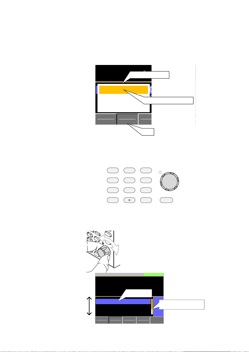
For some parameters, a popup window will also
appear. Selection of the setting is the same.
Repeatedly pressing the relevant function key
(F1~F5) will cycle through each setting. The
selection on the popup window will also be
reflected on the label.
ModeCCI Range
H 35A
V Range
L 15V
Function
Static
Configure
0.000
V
0.000
A
0.00
w
SlewRate 2500.00
CC B Value 0.000
CC A Value 0.000
LOADRS232SHORT
A Value
Fine
03/09/12
mA/uS
A
A
LOW
Middle
High
0.35A
3.5A
35A
label
Popup window
Parameter selection
Parameter
Input
The scroll wheel, Enter key and number pad
can be used to edit parameter values.
Number pad
Scroll wheel
Enter key
P0
P1
P4
P7
CAL.
P2
P5
P8
Lock
P3
P6
P9
0
1
4
7
2
5
8
3
6
9
Clear Enter
1. Use the scroll wheel to move the cursor to the
desired parameter.
A scroll bar is shown when there are additional
parameters off-screen.
ModeCPI Range
H 35A
V Range
L 15V
Function
Dynamic
Configure
0.000
V
0.000A
0.00w
Timer1 0. 025
Level 2 0.00
Level
1
0.00
LOADRS232
Fine
31/Oct/2013
ms
W
W
Scroll bar
Cursor
24
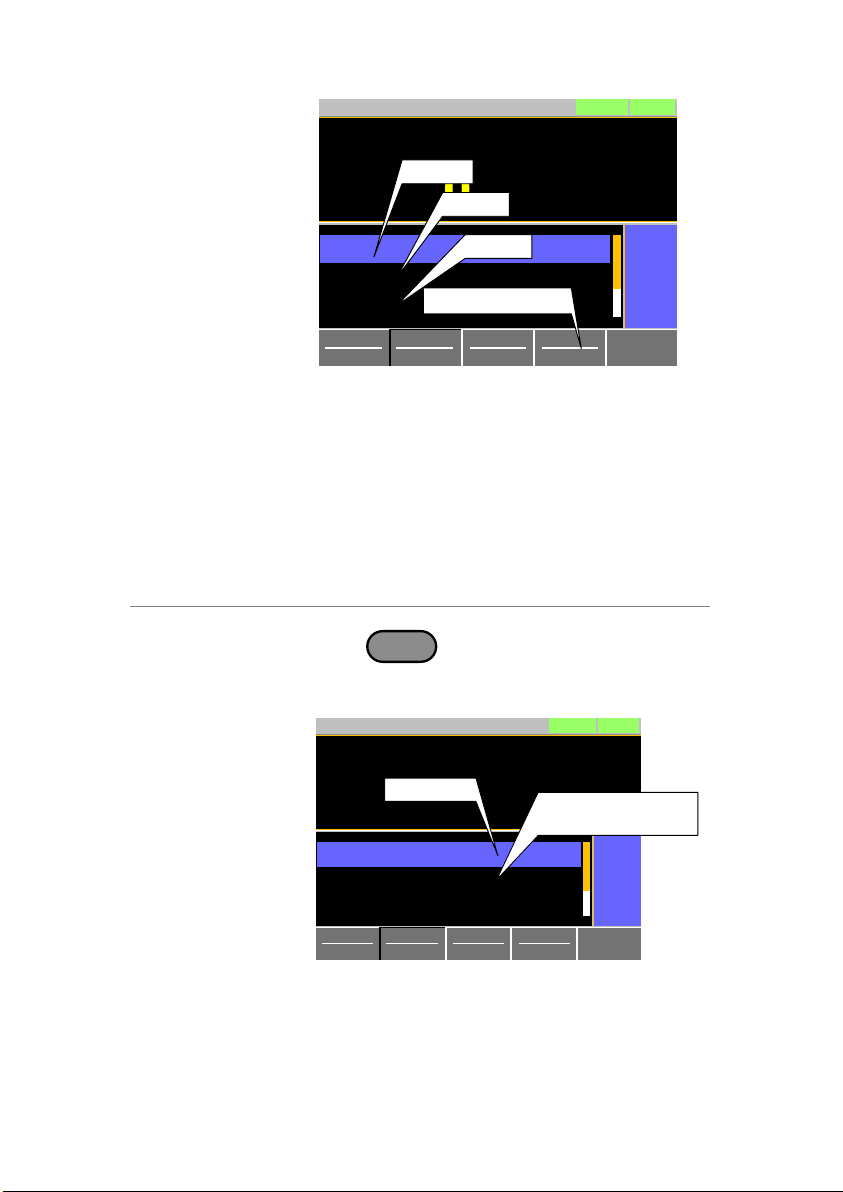
2. Press the Enter key to select the parameter. The
parameter will become highlighted in white.
3. Then use the number pad* or scroll wheel** to
edit the parameter value.
ModeCCI Range
H 35A
V Range
L 15V
Function
Static
Configure
0.000
V
0.000A
0.00w
SlewRate 2500.00
CC B Value
CC A Value 0. 000
LOADRS232
A Value
Fine
31/Oct/2013
mA/us
A
A
1.000
Parameter
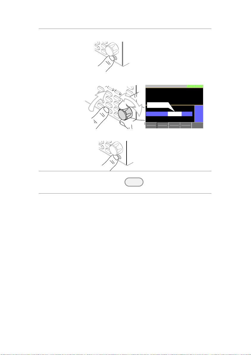
4. Press the Enter key again to finish editing the
parameter value.
Clearing a Value
*When editing a parameter with the number pad,
pressing the
Clear
key will restore the
parameter to the previous value.
Using the Scroll
Wheel to Edit a
Parameter**
**To edit a parameter using the scroll wheel,
simply turn the scroll wheel. Clockwise
increases the value, counterclockwise decrease
the value.
Pressing the scroll wheel when a parameter is
highlighted allows you to change the step
resolution. There are two different step
resolution methods: Step Mode and Cursor
Mode.
25
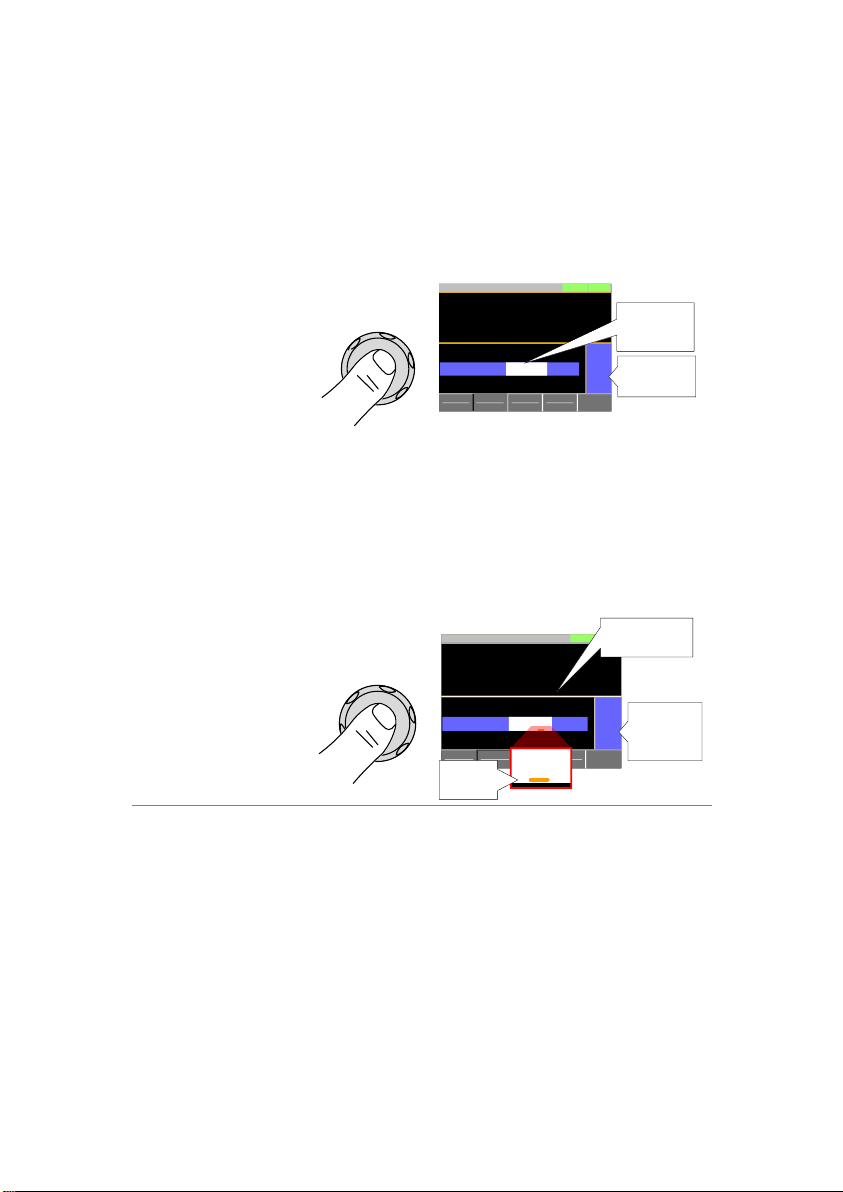
Step Mode:
This is the default step resolution method
and will only be available to use when it is
applicable (Indicated by Fine or Coarse in
the Operation Status panel).
When a parameter is highlighted (step 3
above) pressing the scroll wheel will toggle
the step resolution between fine and coarse.
For details on how to set the step resolution
ModeCCI Range
H 35A
V Range
L 15V
Function
Static
Configure
0.000
V
0.000A
0.00w
SlewRate 2500.00
CC B Value
CC A Value 0.000
LOADRS232
A Value
Fine
31/Oct/2013
mA/us
AA1.000
+
Coarse/Fine
adjustment
Highlighted
parameter
Cursor Mode:
This method must first be enabled before it
can be used. Pressing the scroll wheel when
a parameter is highlighted allows you to set
the step resolution by a digit value. An
orange line will appear under the currently
selected digit value. Repeatedly pressing the
scroll wheel moves to the next digit.
ModeCCI Range
H 35A
V Range
L 15V
Function
Static
Configure
0.000
V
0.000A
0.00w
SlewRate 2500.00
CC B Value
CC A Value 0.000
LOADRS232
A Value
Cursor
31/Oct/2013
mA/us
AA1.000
+
Cursor
Mode
Indicator
0.00
w
LOADRS232
A
A
Highlighted
parameter
Cursor
position
Entering
Alphanumeric
Characters
When renaming files, creating memos or notes,
you will be required to enter alphanumeric
characters when the character entry screen
appears.
Only alphanumeric characters as well as space
[ ], underscore [_] and minus [-] characters
allowed.
26

1. Use the scroll wheel to move the cursor to the
desired character.
A B C D E F G H I J K L M
N O P Q R S T U V W X Y Z
1 2 3 4 5 6 7 8 9 0 _ 1
Rename:
Filename
Cursor
2. Press the
Enter
key or Enter
Character[F1] to select a character.
OR
Enter
Character
3. To delete a character, press Back Space[F2].
4. To save the file name or memo, press Save[F3].
Help Selection
1. Press any function key or soft-menu key.
2. Press
Help
to see the help contents on that
particular function key or menu.
3. Use the scroll to navigate the help contents.
4. Press the Exit[F5] key to exit the help menu.
LOADRS232
31/Oct/2013
Exit
HELP
Press F5 to exit the Help mode.
Rotate the VARIABLE knob to scroll all
the contents.
-End-
1-4-14. Help Menu
When any function key has been pressed or when a menu has been
opened, the HELP key can be used to display a detailed description.
27
Description
In Constant Current Mode the load units will sink
the amount of current programmed. Regardless
of the voltage, the current will stay the same. For
more details on CC mode, please see the
appendix on page 133.
Warning
If you change the mode or the range when the
load is already on, the load will be turned off
automatically.
Operation
1. Make sure the load is off.
2. Press
Main
.
3. Select CC mode with the Mode[F1] soft-key.
4. Select the current range with the I Range[F2]
soft-key.
Range:
High, Middle, Low
5. Select the voltage range with the V Range[F3]
soft-key.
Range:
High, Low
6. Set the current level parameters using the scroll
wheel and number pad.
For Static mode, set CC A Value and/or CC B
Value.
For Dynamic mode, set Level1 and Level2.
The maximum and minimum current levels
depend on the selected ranges.
7. To add CV mode to CC mode (CC+CV), see
page 33.
8. Set the remaining basic configuration settings
such as the slew rate, and switching mode
settings. See page 37 for details.
2. OPERATION
2-1. Basic Operation
The LSG Series supports 7 main operating modes:
CC, CC+CV, CR, CR+CV ,CV ,CP, CP+CV
2-1-1. CC Mode
28

Display
ModeCCI Range
H 35A
VRange
L 15V
Function
Static
Configure
0.000
V
0.000
A
0.00
w
SlewRate 2500.00
CC B Value 0.000
CC A Value 0.000
LOADRS232
A Value
Fine
31/Oct/2013
mA/uS
A
A
Mode
Current range
Voltage range
Active setting
Current setting A
Current setting B
Note
Basic CC mode configuration is complete. See
page 37 for more configuration options.
The current range and voltage range applies to
all the operating modes.
Description
In Constant Resistance Mode, the unit will
maintain a constant resistive load by varying the
current. CR mode uses ohms, Ω (resistance) or
siemens,S (conductance) for the setting units.
For more details on CR mode, see the appendix
on page 134.
Warning
If you change the mode or the range when the
load is already on, the load will be turned off
automatically.
Operation
1. Make sure the load is off.
2. Press
Main
.
3. Select CR mode with the Mode[F1] soft-key.
4. Select the current range with the I Range[F2]
soft-key.
Range:
High, Middle, Low
5. Select the voltage range with the V Range[F3]
soft-key.
Range:
High, Low
2-1-2. CR Mode
29

6. Set the resistance or conductance level
parameters using the scroll wheel and number
pad.
For Static mode, set CR A Value and/or CR B
Value.
For Dynamic mode, set Level1 and Level2.
The maximum and minimum conductance/
resistance levels depend on the selected
current range.
7. To add CV mode to CR mode (CR+CV), see
page 33.
8. Set the remaining basic configuration settings
such as the slew rate, and switching mode
settings. See page 37 for details.
Display
ModeCRI Range
H 35A
V Range
L 15V
Function
Static
Configure
0.000
V
0.000
A
0.00
w
SlewRate 250.000
CR B Value 0.04082
CR A Value 0.04082
LOADRS232
A Value
Fine
31/Oct/2013
mA/uS
Ω
Ω
Mode
Current range
Voltage
range
Active
setting
Conductance/
Resistances
Conductance/
Resistance
settings
Note
Basic CR mode configuration is complete. See
page 37 for more configuration options.
The current range and voltage range applies to
all the operating modes.
Description
The CR setting units can be set to ohm (Ω) or
milli-siemens (mS).
Operation
1. Make sure the load is off.
2. Press
Main
> Configure[F5] > Other[F2] and
set the CR Unit setting.
Range:
Ω (resistance) or milli-siemens,mS
(conductance) for the setting units.
2-1-3. CR Units
30

Description
In Constant Voltage Mode, the unit will maintain
a constant voltage. In CV mode you set the
constant voltage level. For more details on CV
mode, see the appendix on page 136.
Warning
If you change the mode or the range when the
load is already on, the load will be turned off
automatically.
Operation
1. Make sure the load is off.
2. Press
Main
.
3. Select CV mode with the Mode[F1] soft-key.
4. Select the current range with the I Range[F2]
soft-key.
Range:
High, Middle, Low
5. Select the voltage range with the V Range[F3]
soft-key.
Range:
High, Low
6. Set the voltage level parameters using the scroll
wheel and number pad.
Set CV A Value and/or CV B Value.
The maximum and minimum voltage levels
depend on the selected voltage range.
7. Set the remaining basic configuration settings
such as the response settings. See page 37 for
details.
Display
ModeCVI Range
H 35A
V Range
L 15V
Response
Slow
Configure
0.000
V
0.000
A
0.00
w
CV B Value 15.000
CV A Value 15.000
LOADRS232
A Value
Fine
31/Oct/2013
V
V
Mode
Current range
Voltage
range
Active
setting
Current
setting
Voltage
settings
Note
Basic CV mode configuration is complete. See
page 37 for more configuration options.
The current range and voltage range applies to
all the operating modes.
2-1-4. CV Mode
31

Description
In Constant Power Mode, the unit will maintain a
constant power by varying the current. For more
details on CP mode, see the appendix on page
135.
Warning
If you change the mode or the range when the
load is already on, the load will be turned off
automatically.
Operation
1. Make sure the load is off.
2. Press
Main
.
3. Select CP mode with the Mode[F1] soft-key.
4. Select the current range with the I Range[F2]
soft-key.
Range:
High, Middle, Low
5. Select the voltage range with the V Range[F3]
soft-key.
Range:
High, Low
6. Set the power level parameters using the scroll
wheel and number pad.
For Static mode, set CP A Value and/or CP B
Value.
For Dynamic mode, set Level1 and Level2.
The maximum and minimum power levels
depend on the selected current range.
For static mode, the parameter that is set last
becomes the “active” setting. This will be
shown in the Operation Status Panel.
7. To add CV mode to CP mode (CP+CV), see
page 33.
8. Set the remaining basic configuration settings
such as the slew rate, and timer settings. See
page 37 for details.
2-1-5. CP Mode
32

Display
ModeCPI Range
H 35A
V Range
H 150V
Function
Static
Configure
0.00
V
0.000
A
0.00
w
CP B Value 0.00
CP A Value 0.00
LOADRS232
A Value
Fine
31/Oct/2013
W
W
Current range
Active
setting
Current
setting
Power
settings
+CV OFF
Mode
Voltage
range
Note
Basic CP mode configuration is complete. See
page 37 for more configuration options.
The current range and voltage range applies to
all the operating modes.
Description
CV mode can be added to CC, CR and CP
mode.
The +CV settings apply to all applicable modes.
Operation
1. Make sure the load is off.
2. Press
Main
to return to the main menu for
the current mode.
3. Set the +CV voltage level. (You may need to
scroll down to the +CV setting)
Range:
OFF ~ rated voltage+5%
Display
ModeCPI Range
H 35A
V Range
L 15V
Function
Dynamic
Configure
0.000
V
0.000
A
0.00
w
+CV 5.500
Timer2 0.025
Timer1 0.025
LOADRS232
Fine
31/Oct/2013
V
mS
mS
+CV setting
2-1-6. +CV Mode
33

Note
The +CV settings apply to all the applicable
operating modes.
For example: The +CV settings made in CR
mode will be carried over to the +CV settings in
CC and CP mode.
Note
+CV settings cannot be controlled with external
control.
Description
1. The load can be turned on and off by pressing the
Load
On/
Off
key.
The
Load
On/
Off
key will turn orange when the load
is “on”.
The LOAD icon in the Main Frame status panel
will turn orange when the load is on.
Note
The load can be set to automatically turn on at
start up. See page 45.
The load can be turned on via remote control.
See the programming manual.
The load can be turned on via external control.
See page 109.
Display
LOADRS232
31/Oct/2013
LOAD on
Description
The Short key can be used to simulate a short
circuit of the load input terminals. A short circuit
is simulated by:
Setting the current to the maximum value in CC
mode.
Setting the resistance to the minimum value in
CR mode.
Setting the voltage to the minimum value in CV
mode.
Setting the power to the maximum value in CP
mode.
When the load is shorted, the external
controller also sends a short signal. See page
112 for usage details.
2-1-7. Turning on the Load
2-1-8. Shorting the Load
34

Operation
1. The short function can be turned on and off by
pressing the
Short
key.
The
Short
key will turn red when the short
function is active.
The Short icon will appear when the short
function is active.
Range:
Toggle, Hold
Display
LOADRS232SHORT
31/Oct/2013
SHORT on
Note
If the load is already off, pressing the Short key
will turn the load on (shorted) at the same time.
Pressing the Short key again will also turn the
load off again as well.
If the load is already on and the Short key is
pressed, then when the Short key is pressed
again the load will remain on (the electronic load
will return to its previous load condition).
Description
When activated, the safety short function only
allows the short key to be used when the load is
already on.
Operation
1. Press
Main
> Configure[F5] > Other[F2] and
set the Short Safety.
When set to OFF, the load can be shorted at
anytime.
When set to ON, the load can only be shorted
when the load is already on.
Short(Safety)
:
OFF,ON
Note
The Short Safety setting will be grayed out if Short
Function is set to OFF.
2-1-9. Safety Short
35

Description
The Short key can be configured to Toggle or
Hold. By Default the Short key is set to Toggle.
Toggle: Pressing the Short key will toggle the
shorting function on or off.
Hold: Holding the short key will short the load.
Operation
1. Press
Main
> Configure[F5] > Other[F2] and
set the Short Key setting.
Range:
Toggle, Hold
Description
The short key can be disabled to prevent
the operator accidentally shorting the load.
Operation
1. Press
Main
> Configure[F5] > Other[F2] and
set the Short Function.
When set to OFF, the Short key is disabled
and all short configuration options in the Main
> Configure> Other menu are also disabled.
When set to ON, the Short key is enabled.
Short Function:
OFF,ON
Description
The keys and scroll wheel on the front panel can
be locked to prevent settings from being
changed.
Operation
1. The keys can be locked and unlocked by
pressing
Shift
+
Lock
Clear
.
LOCK will appear in the Mainframe status
panel when the keys are locked.
The
Load
On/
Off
key will not be locked if the load
is on.
Display
LOADRS232
31/Oct/2013
LOCK
LOCK icon
2-1-10. Short Key Configuration
2-1-11. Short Function Enable/Disable
2-1-12. Locking the Front Panel Controls
36
Description
The LSG Series has two switching modes, static
and dynamic. The switching modes allow the
LSG Series to switch between two preset levels.
Static mode can only switch between the two
levels manually, while Dynamic mode switches
between each level automatically based on a
timer.
Static mode: A Value, B Value
Dynamic mode: Level1, Level2
When the unit is set to static mode, only one
value (A Value or B Value) can be active at a
time. The active value is shown in the Operation
Status Panel.
Configure
w
LOADRS232SHORT
A Value
Fine
Active setting
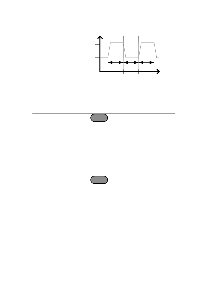
When the unit is set to dynamic mode, the unit
will switch between Level1 and Level2 based on
the Timer1 and Timer2 parameters, shown
below.
Level
Time
Level 2
Level 1
Timer1 Timer2 Timer1
Dynamic Mode
Note
Dynamic mode is not available for CV mode.
2-2. Basic Configuration
The basic configuration settings are the common configuration
settings that are used for each operating mode. After selecting a
basic operating mode (CC, CR, CV or CP mode), the slew rate,
switching mode, response rate and other common parameters should
be configured.
2-2-1. Select the Switching Function
37
Operation
1. Make sure the load is off.
2. Press
Main
.
3. Select Dynamic or Static mode with the
Function[F4] soft-key.
A different switching mode can be set for CC,
CR and CP mode.
4. For dynamic mode, set the Timer1 and Timer2
parameters using the scroll wheel and number
pad.
Timer1 sets the Level1 on-time.
Timer2 sets the Level2 on-time.
Take the slew rate settings into consideration
when setting the timers.
The frequency of the dynamic switching is
output via the TRIG OUT BNC.
To select whether A Value or B Value is the
“active” setting, press the
Shift
+
Preset
keys.
The “active” value will be shown in the
Operation Status Panel.
The load can be “on” when switching between
A Value and B Value.
Display:
Static Mode
ModeCPI Range
H 35A
V Range
H 150V
Function
Static
Configure
0.00
V
0.000
A
0.00
w
CP B Value 0.00
CP A Value 0.00
LOADRS232
A Value
Fine
31/Oct/2013
W
W
Active setting
B Value
+CV OFF V
Static mode
38
Display:
Dynamic Mode
ModeCPI Range
H 35A
V Range
L 15V
Function
Dynamic
Configure
0.000
V
0.000
A
0.00
w
Timer1 0.025
Level2 0.00
Level1 0.00
LOADRS232
Fine
31/Oct/2013
mS
W
W
Dynamic mode
Level1
Level2
Timer1
Description
When Dynamic switching mode is selected, the
Level1 and Level2 values can be set to either
discrete values or as a percentage of a set
value.
The setting applies to all applicable operation
modes.
By default the units are set to Value.
When Percent is chosen, 100% = 100% of the
Set power, current or resistance value.
Operation
1. Make sure the load is off.
2. Press
Main
> Configure[F5] > Other[F2] and
set the Dyna. Level setting.
Range:
Value, Percent
Display:
Percent Setting
ModeCPI Range
H 35A
V Range
L 15V
Function
Dynamic
Configure
0.000
V
0.000
A
0.00
w
Timer1 0.025
Level 50.0
Set 1.00
LOADRS232
Fine
31/Oct/2013
ms
%
W
Set level
% from the Set
value
2-2-2. Select the Display Units for Dynamic Mode Levels
39
Example
Level
Time
Set
Level
Timer1 Timer2 Timer1
Dynamic Mode:
Dyna. Level = Percent
Description
The switching time for dynamic mode can be
configured to switch between two preset ontimes (Timer1, Timer2) or by setting a switching
frequency and duty cycle.
Operation
1. Press
Main
> Configure[F5] > Other[F2] and
set the Dyna. Time setting.
Range:
T1/T2, Freq. Duty
Description
The current slew rate can be set for CC and CR
mode. The slew rate setting is used to limit the
change in current when switching.
For static mode, only a single slew rate can be
set.
Operation
1. Make sure the load is off.
2. Press
Main
.
3. Set the slew rate(s) using the scroll wheel and
number pad.
For static mode, only a single slew rate can be
set.
For dynamic mode, set both the rising and
falling slew rates.
Take the timer settings into consideration when
setting the slew rates.
2-2-3. Select the Switching Time Configuration for Dynamic
Mode
2-2-4. Slew Rate
40
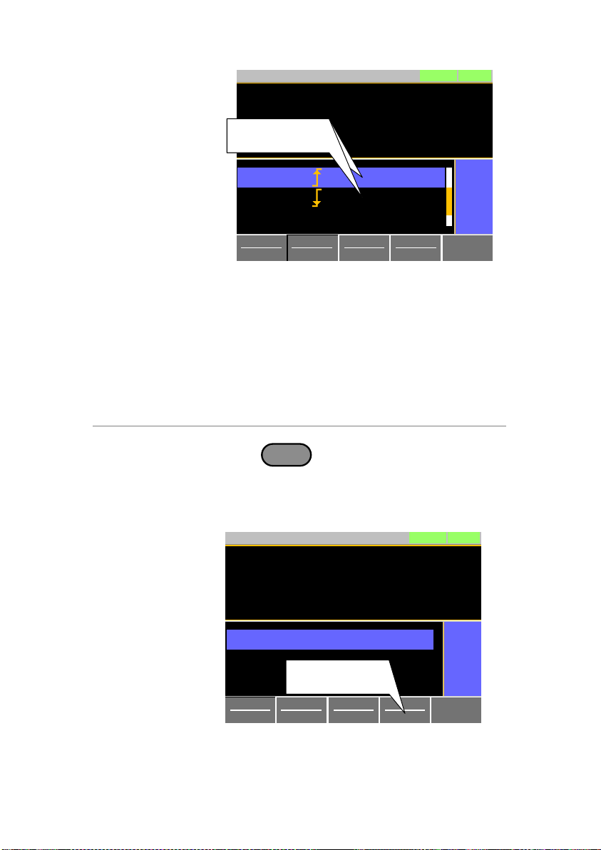
Display
ModeCCI Range
H 35A
V Range
H 150V
Function
Dynamic
Configure
0.00
V
0.000
A
0.00
w
Timer1 0.025
SlewRate 2500.00
SlewRate 2500.00
LOADRS232
Fine
31/Oct/2013
ms
mA/us
mA/us
Slewrate
settings
Slewrate
settings
Description
The response speed setting is the response
speed for the negative feedback control of the
load current when used in CV mode. Response
speed settings are only applicable to CV mode.
A response speed that is too fast could cause
the unit to be unstable.
Reducing the response speed can improve
stability.
Operation
1. Make sure the load is off.
2. Press
Main
. Make sure the unit is in CV
mode by using the Mode[F1] soft-key.
3. Select the response speed with the
Response[F4] soft-key.
Range:
Slow, Fast
Display
ModeCVI Range
H 35A
V Range
L 15V
Response
Slow
Configure
0.000
V
0.000
A
0.00
w
CV B Value 15.000
CV A Value 15.000
LOADRS232
A Value
Fine
31/Oct/2013
V
V
Response
setting
2-2-5. CV Mode Response Speed
41
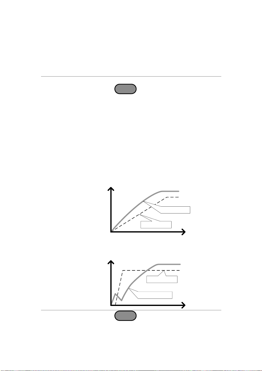
Description
By default, the “normal current response” speed
is set to 1/1. The response speed can be
reduced to 1/2, 1/5, 1/10.
Reducing the current response speed can
affect other settings such as the slew rate and
soft start settings.
Operation
1. Make sure the load is off.
2. Press
Main
> Configure[F5] > Other[F2] and
set the Response parameter.
Range:
1/1,1/2,1/5,1/10
Description
The soft start setting is used to limit the amount
of input current at start-up or from when the Von
Voltage threshold is tripped.
The soft start setting only applies to CC & CR
mode.
Input I
Time
Soft Start = ON
Input I
Time
Soft Start= OFF
Rise voltage
Rise current
Rise current
Rise voltage
Operation
1. Press
Main
> Configure[F5] > Other[F2] and
set the Soft Start time.
Range:
OFF, 1~200ms
2-2-6. CC,CR and CP Mode Response Speed
2-3. Advanced Configuration Settings
Use the advanced configuration settings to configure settings other
than those described in the basic configuration chapter.
2-3-1. Soft Start Setting
42
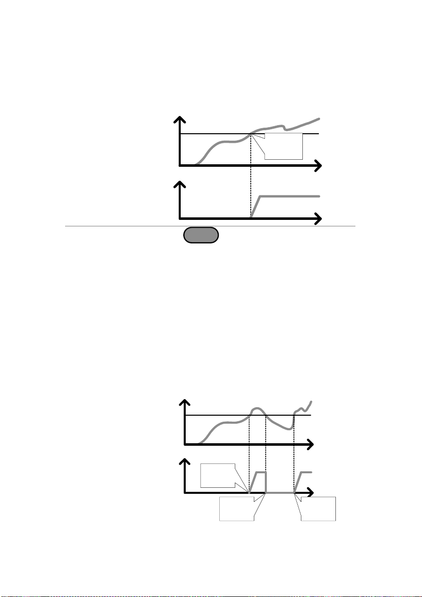
Description
The Von Voltage is the threshold voltage at
which the load module will start to sink current.
Time
Von voltage
Von
V
Time
I
V out
Load
on
Operation
1. Press
Main
> Configure[F5] > Other[F2] and
set the Von Voltage level.
Range:
Von Voltage: 0.00~rating voltage
Description
When Von Latch is set to ON, the load will
continue to sink current after being “latched”,
even if the voltage drops below the Von Voltage
threshold level.
When Von Latch is set to OFF, the load will turn
off when the voltage drops below the Von
Voltage threshold level.
By default Von Latch is set to OFF.
Time
Von Latch = OFF
Von
V
Time
I
V out
Load
on
Load
off
Load
on
2-3-2. Von Voltage Settings 2-3-2-1. Von Voltage Level
2-3-2-2. Von Voltage Latch
43
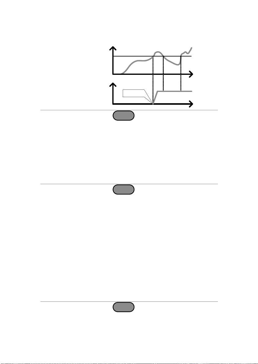
Time
Von Latch = ON
Von
V
Time
I
V out
Load on
Operation
1. Press
Main
> Configure[F5] > Other[F2] and
set the Von Latch setting.
Range:
Von Latch: OFF, ON
Description
Von Delay is the amount of time the unit will wait
before turning the load on after the Von Voltage
threshold has been latched. This will prevent
overshoot current from affecting the Von Voltage
threshold.
Operation
2. Press
Main
> Configure[F5] > Other[F2] and
set the Von Delay time.
Range:
Von Delay: OFF, 0.5~60ms
CR mode can have the delay time set separately
from the other modes (called Von Delay –CR when
in CR mode).
Description
When Count Time is set to on, it will count the
elapsed time from when the load was turned on
to when it was turned off.
This function is applicable to manual and
automatic shutdown (such as from protection
functions such as UVP etc.)
The elapsed time will be shown in the display
Measurement area.
Operation
1. Press
Main
> Configure[F5] > Other[F2] and
turn the Count Time on or off.
Range:
ON, OFF
2-3-2-3. Von Voltage Delay
2-3-3. Timer Functions 2-3-3-1. Count Time
44
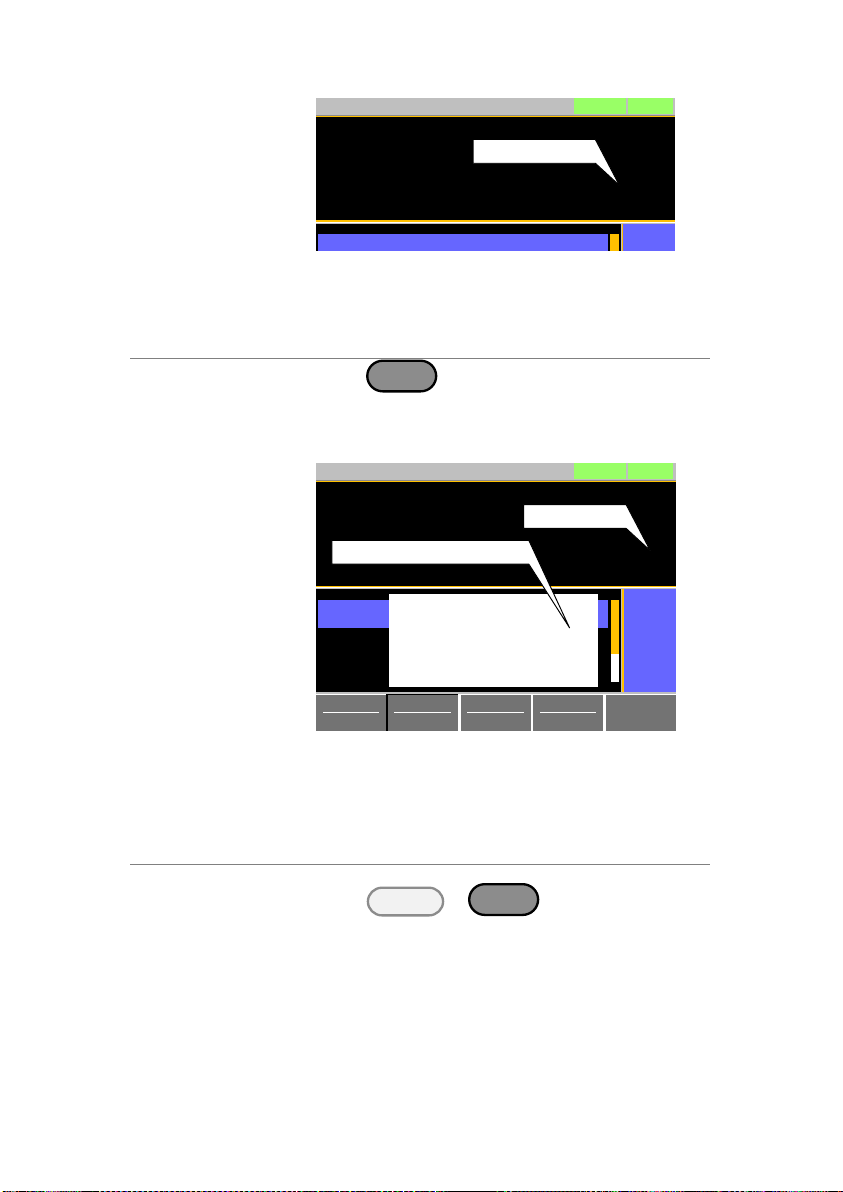
Display
0.000
V
0.000
A
0.00
w
LOADRS232
31/Oct/2013
0:00:05
Elapsed time
Description
The Cut Off Time function will turn the load off
after a set-amount of time. After the load has
been turned off, a popup screen will display the
voltage level when the load was turned off.
Operation
1. Press
Main
> Configure[F5] > Other[F2] and
set the Cut Off Time.
Range:
OFF, 1 second –
999 hours:59minutes:59 seconds
Display
ModeCPI Range
H 35A
V Range
L 15V
Function
Dynamic
Configure
0.000
V
0.000
A
0.00
w
Timer1 0.025
Level2 0.00
Level1 0.00
LOADRS232
Fine
31/Oct/2013
mS
W
W
0:00:05
Cut off time
Time Up
Voltage : 5.1223V
Enter
Voltage at cut off time
Description
The LSG Series can be configured to
automatically load the last program, normal
sequence, fast sequence or load setting at
startup.
By default, this setting is disabled.
Operation
1. Press
Shift
+
Utility
Help
> Load[F2].
2. Turn Auto Load On or Off.
When set to OFF, the Auto Load setting is
disabled.
3. Select the Auto Load On configuration.
This will select whether the LSG Series will
automatically load the last program, normal
sequence, fast sequence or load settings.
Auto Load On:
Load, Prog, NSeq, FSeq
2-3-3-2. Cut Off Time
2-3-4. Auto Load Configuration
45

Description
By default the load will automatically turn off
when the either the operating mode (CC, CV,
CR, CP) or the range (I range, V range) is
changed.
To allow the load to stay on when the operating
mode is changed, set the Load Off (Mode)
setting to OFF.
To allow the load to stay on when the current or
voltage range is changed, set the Load Off
(Range) setting to OFF.
By default, these settings are set to ON.
Operation
1. Press
Shift
+
Utility
Help
> Load[F2].
2. Select Load Off (Mode) setting.
When set to OFF, the load will stay on when
the operating mode is changed.
Load Off(Mode):
OFF,ON
3. Select Load Off (Range) setting.
When set to OFF, the load will stay on when
the range is changed.
Load Off(Range):
OFF,ON
Description
Cursor mode allows you to edit the selected
parameter one digit at a time. When editing a
parameter, pressing the scroll wheel determines
which digit is selected. Turning the scroll wheel
will then edit the parameter by the step
resolution of the digit.
Operation
1. Press
Main
> Configure[F5] > Next Menu
[F4] > Knob[F2] and set the Status setting is set
to Cursor.
2-3-5. Load Off (Mode) and Load Off (Range)
2-4. Step Resolution Configuration
There are two different ways to set the set resolution when using the
scroll wheel to edit parameters. Step Mode and Cursor Mode. Step
Mode is the default method. Only one mode can be active at a time;
When one mode is active, the other mode is deactivated.
2-4-1. Cursor Mode Configuration
46

Display
Parallel Knob External
Previous
Menu
0.4
CCL Step 0.183575
CCM Step 0.5000
LOADRS232
31/Oct/2013
mS
A
A
CRH Step
CCH Step
Status
1.000
CursorA
CC
35A
15V
Static
Configure
Description
When set to Step Mode, the voltage, current,
resistance and power settings can have the step
resolution configured. The step resolution refers
to the step resolution of the coarse adjustment
for these settings. The fine adjustment cannot be
configured.
Settings
The step resolution of each setting is configured
separately for each current range.
Settings
Description
CCH Step
CC mode, IRange = High
CCM Step
CC mode, IRange = Middle
CCL Step
CC mode, IRange = Low
CRH Step
CR mode, IRange = High
CRM Step
CR mode, IRange = Middle
CRL Step
CR mode, IRange = Low
CVH Step
CV mode, VRange = High
CVL Step
CV mode, VRange = Low
CPH Step
CP mode, IRange = High
CPM Step
CP mode, IRange = Middle
CPL Step
CP mode, IRange = Low
Operation
1. Press
Main
> Configure[F5] > Next
Menu[F4] > Knob[F2] and set the desired step
resolution settings.
2. Set the desired step resolution settings. (The
step resolution settings are only available when
Status=Step)
For example if the step resolution for CCM Step
is 0.5A, then the resolution can be incremented
in 0.5A steps.
2-4-2. Step Mode Configuration
47

Display
Parallel Knob External
Previous
Menu
CRH Step 0.4
CCL Step 0. 183575
LOADRS232
31/Oct/2013
Step
mS
A
CCM Step
CCH Step
0.5000
1.000AA
CC
35A
15V
Static
Configure
Status
Description
For OCP, the LSG Series can be configured to
either limit the current or turn off the load.
The OCP levels can be set to 10% higher than
the rating current.
Operation
1. Press
Main
> Configure[F5] > Protection[F1]
and set the OCP Level and OCP Setting.
Range:
OCP Level: Rating current + 10%
OCP Setting: LIMIT, Load Off
Alarm
When OCP Setting is configured to Load Off, a
message will be displayed on the screen when
OCP is tripped. The Enter key must be pressed
to clear the alarm message.
When configured to LIMIT, OCP will be
displayed on the screen when the OCP is
tripped and the current will be limited to the
OCP Level setting.
2-5. Protection Settings
The Protection settings are used to prevent damage to the unit or the
DUT by excessive current, voltage or power.
An alarm is generated and a message is displayed on the screen
when a protection setting is tripped. When an alarm is activated, the
load is turned off (or limited), and the ALARM STATUS pin of the J1
connector on the rear panel (pin 16) turns on (open collector output
by a photocoupler). The protection settings can be used regardless of
whether the remote sense connections are used or not.
2-5-1. OCP
48

Display
2.596
V
500.06
mA
1.2982
w
CV B Value 15.000
CV A Value 15.000
LOADRS232
A Value
Fine
03/09/12
V
V
OCP Alarm
Please Press Enter
To Clear Alarm
OCP
OCP indicator
Alarm message
when OCP is
set to Load Off
ModeCVI Range
L 0.7A
V Range
L 15V
Response
Fast
Configure
Description
For OPP, the LSG Series can be configured to
either limit the power or turn off the load.
The OPP levels can be set to 10% higher than
the rating power.
Operation
1. Press
Main
> Configure[F5] > Protection[F1]
and set the OPP Level and OPP Setting.
Range:
OPP Level: Rating power + 10%
OPP Setting: LIMIT, Load Off
Alarm
When OPP Setting is configured to Load Off, a
message will be displayed on the screen when
OPP is tripped. The Enter key must be pressed
to clear the alarm message.
When configured to LIMIT, OPP will be
displayed on the screen when the OPP is
tripped and the power will be limited to the OPP
Level setting.
Display
2.596V
500.06 mA
1.2982w
CV B Value 15.000
CV A Value 15.000
LOADRS232
A Value
Fine
03/09/12
V
V
OPP Alarm
Please Press Enter
To Clear Alarm
Alarm message
when OPP is
set to Load Off
ModeCVI Range
L 0.7A
V Range
L 15V
Response
Fast
Configure
OPP
OPP indicator
2-5-2. OPP
49
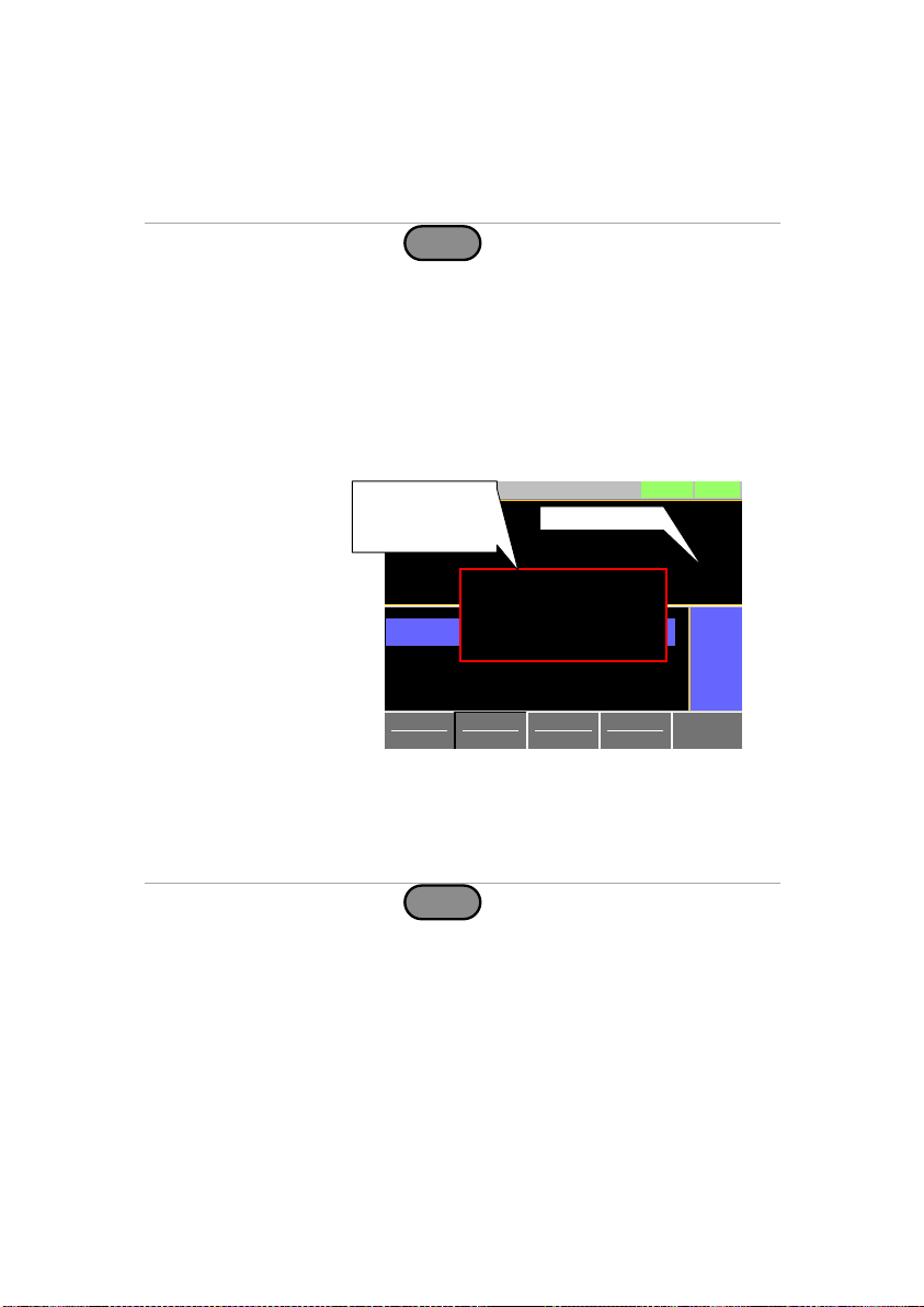
Description
If the UVP is tripped, the LSG Series will turn off
the load.
The UVP levels can be set from 0V to 10%
higher than the rating voltage.
Operation
1. Press
Main
> Configure[F5] > Protection[F1]
and set the UVP Level.
Range:
UVP Level: OFF, 0~Rating voltage + 10%
Alarm
The UVP indicator will only appear on the
screen when the input voltage is below the
UVP level.
Pressing the Enter key will clear the message.
The UVP indicator will remain on the display
until the voltage level rises back above the UVP
level.
Display
2.596
V
500.06
mA
1.2982
w
CV B Value 15.000
CV A Value 15.000
LOADRS232
A Value
Fine
03/09/12
V
V
UVP Alarm
Please Press Enter
To Clear Alarm
UVP
UVP indicator
Alarm message
when UVP is
tripped
ModeCVI Range
L 0.7A
V Range
L 15V
Response
Fast
Configure
Description
The UVP Ring Time settings allows the UVP
alarm to keep sounding for a user-set amount of
time after the UVP has been tripped.
Operation
1. Press
Main
> Configure[F5] > Protection[F1]
and set the UVP Ring Time.
Range:
UVP Ring Time: OFF, 0~600s
Alarm
When the voltage dips below the UVP level, the
UVP indicator and message will appear on the
screen. The UVP buzzer will sound if UVP Ring
Time is set.
Pressing the Enter key will clear the message
and the buzzer.
If the voltage rises back above the UVP level,
the buzzer will continue to sound until the UVP
Ring Time has elapsed.
2-5-3. UVP
2-5-4. UVP Ring Time
50

Description
If the OVP is tripped, the LSG Series will turn off
the load. The OVP levels can be set from 0V to
10% higher than the rating voltage.
Operation
1. Press
Main
> Configure[F5] > Protection[F1]
and set the OVP Level.
Range:
OVP Level: OFF, 0~Rating voltage + 10%
Note: To turn OVP off, set the OVP voltage
greater than the current rating voltage + 10%.
Display
2.596
V
500.06
mA
1.2982
w
CV B Value 15.000
CV A Value 15.000
LOADRS232
A Value
Fine
03/09/12
V
V
OVP Alarm
Please Press Enter
To Clear Alarm
OVP
OVP indicator
Alarm message
when OVP is
tripped
ModeCVI Range
L 0.7A
V Range
L 15V
Response
Fast
Configure
Description
The UnReg error message will appear on the
display when the electronic load is operating in
an unregulated state.
Alarm
The UnReg indicator will appear on the display
when the set load is inadequate for the source.
To clear the UnReg indicator, increase the load
or reduce the load requirements.
Display
2.596
V
500.06
mA
1.2982
w
CV B Value 15.000
CV A Value 15.000
LOADRS232
A Value
Fine
31/Oct/2013
V
V
UnReg
UnReg indicator
ModeCVI Range
L 0.7A
V Range
L 15V
Response
Fast
Configure
2-5-5. OVP
2-5-6. UnReg
51
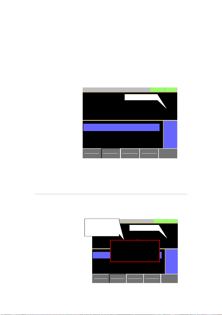
Description
The Para error message will appear on the
display when the LSG is used in parallel
and if an error is produced.
Alarm
The Para error message indicates one of the
following possible conditions: UnReg, R.OCP,
OTP.
To clear the Para indicator, remove the cause
of the alarm.
Display
2.596
V
500.06
mA
1.2982
w
CV B Value 15.000
CV A Value 15.000
LOADRS232
A Value
Fine
03/Sep/2012
V
V
Para
Para indicator
ModeCVI Range
L 0.7A
V Range
L 15V
Response
Fast
Configure
Description
If the RVP is tripped, the LSG Series will turn off
the load.
Alarm
The RVP error message indicates when the
terminal voltage is negative.
The Enter key must be pressed to clear the
alarm message.
Display
2.596
V
500.06
mA
1.2982
w
CV B Value 15.000
CV A Value 15.000
LOADRS232
A Value
Fine
03/09/12
V
V
RVP Alarm
Please Press Enter
To Clear Alarm
RVP
RVP indicator
Alarm message
when RVP is
tripped
ModeCVI Range
L 0.7A
V Range
L 15V
Response
Fast
Configure
2-5-7. Para
2-5-8. RVP
52

Speaker settings
Display settings
Alarm tone settings
Input control settings
Language settings
Input/output trigger setting
Description
Turns the speaker sound on or off for the user
interface, such as key press tones and scrolling
tones.
Operation
1. Press
Shift
+
Utility
Help
> Other[F5].
2. Set the Speaker settings on or off.
When set to OFF, the speaker setting will not
disable the tones for Go-NoGo or protection
alarms.
Description
The alarm tone for the unit during normal
operation and for Go-NoGo testing can be turned
on or off in the utility menu.
Operation
1. Press
Shift
+
Utility
Help
> Other[F5].
2. Set the alarm tone settings on or off.
The alarm tone settings ignore the Speaker
setting.
Alarm Tone:
UnReg Tone:
Go_NoGo Tone:
ON, OFF
ON, OFF
ON, OFF
2-6. System Settings
The following section covers a number or miscellaneous system
settings such as:
All system settings are accessible in the Utility menu.
2-6-1. Sound Settings 2-6-1-1. Speaker Settings
2-6-1-2. Alarm Tone Settings
53
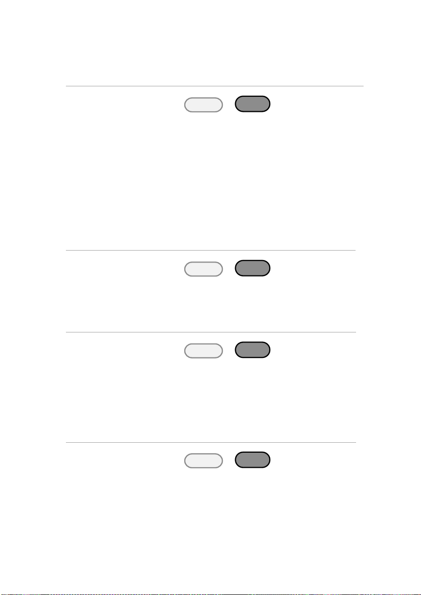
Description
Sets the contrast level.
Operation
1. Press
Shift
+
Utility
Help
> Other[F5].
2. Set the Contrast and Brightness settings.
Range:
Contrast: 3 ~ 13 (low ~ high)
Brightness: 50 ~ 90 (low ~ high)
Description
The Knob Type setting determines if values are
updated immediately as they are edited or if they
are only updated after the Enter key is pressed.
The Updated setting is applicable for when the
load is already on and the user wishes to
change the set values (current, voltage, etc.) in
realtime. The Old setting is will only update the
values after the Enter key is pressed.
Operation
1. Press
Shift
+
Utility
Help
> Other[F5].
2. Set the Knob type and Slave knob settings.
Range:
Knob type: Updated, Old
Description
The LSG Series supports only English.
Operation
1. Press
Shift
+
Utility
Help
> Other[F5].
2. Set the Language setting.
Supported languages:
English
Description
The Trig In Delay setting determines how long to
delay any action after a trigger is received.
Operation
1. Press
Shift
+
Utility
Help
> Other[F5].
2. Set the Trig In Delay setting.
Range:
0.0 – 5000us (Default:0.0us)
2-6-2. Contrast and Brightness
2-6-3. Control Settings
2-6-4. Language Settings
2-6-5. Input/Output Trigger Settings 2-6-5-1. Trigger In Delay
54

Description
The Trigger Out Width setting sets the
trigger output signal’s pulse width.
Operation
1. Press
Shift
+
Utility
Help
> Other[F5].
2. Set the Trig Out width.
Range:
2.5– 5000us (Default:10.0us)
Description
The Go-NoGo setting limits can be set as either
discrete high & low values or as a percentage
offset from a center value.
Operation
1. Press
Main
> Configure[F5] > Go-NoGo[F3].
2. Select Entry Mode and choose how to set the
pass/fail limits.
Value will allow you to set the limits as discrete
values.
Percent will allow you to set the limits as a
percentage offset from a center value.
3. If Entry Mode was set to Value, Set the High &
Low limit values.
High:
Low:
0~rating current/voltage
0 ~rating current/voltage
4. If Entry Mode was set to Percent, Set the Center
voltage/current and High, Low % values.
Center:
High:
Low:
0~rating current/voltage
0~100% of center voltage/current
0~100% of center voltage/current
5. Set the Delay Time.
The delay time setting will delay activating the
Go-NoGo testing by a specified amount of time.
The delay setting can compensate for startup
oscillation and other instabilities during startup.
Delay Time
0.0~1.0 seconds (0.1s resolution )
2-6-5-2. Trigger Out Width
2-7. Go-NoGo
The Go-NoGo configuration is used to create pass/fail limits on
the voltage or current input. If the voltage/current exceeds the
pass/fail limits, an alarm will be output.
The Go-NoGo configuration can be used with the Program
function to create complex pass/fail tests.
2-7-1. Setting the Go-NoGo Limits
55
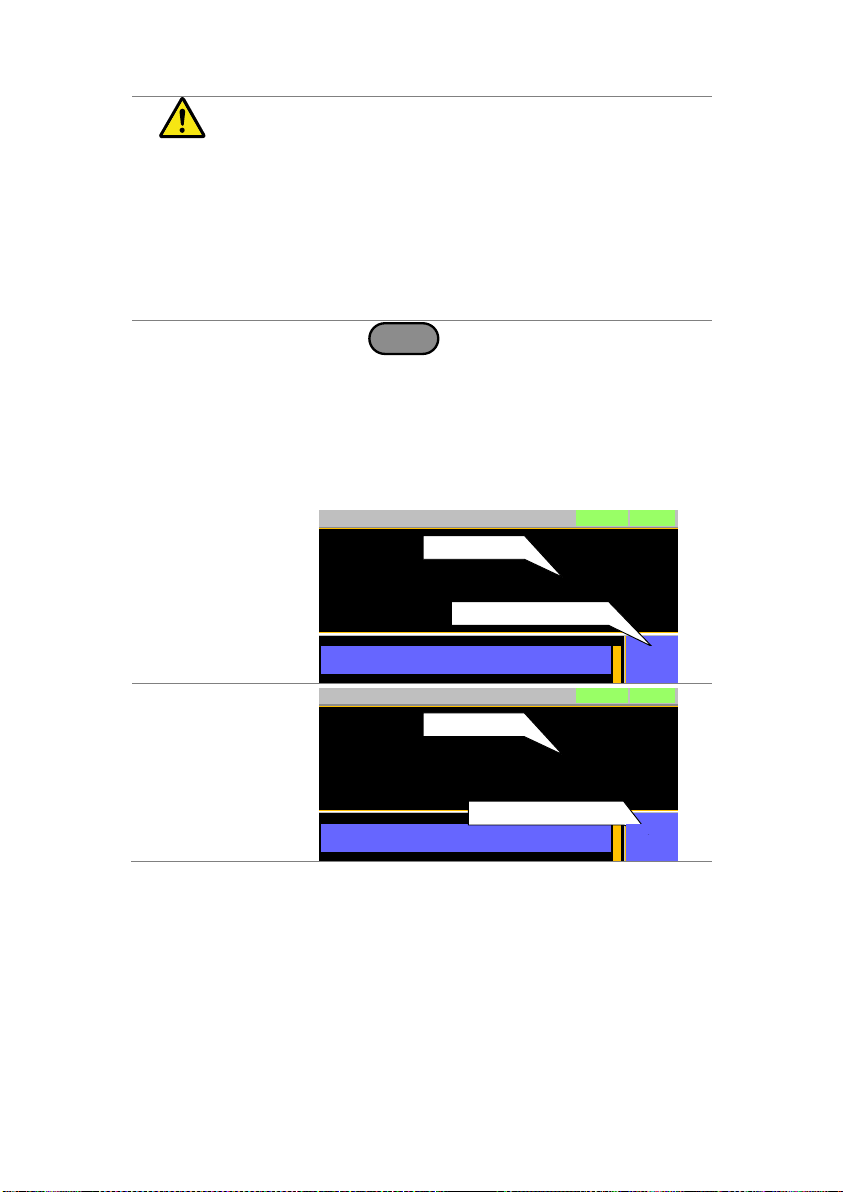
Note
When the Main settings are saved or recalled,
the Go-NoGo settings are also saved/recalled.
See the Save/Recall chapter for details, page
57.
Description
Go-NoGo test results are displayed in the
measurement panel.
GO indicates pass (good).
NG indicates fail (no good).
Operation
1. Press
Main
> Configure[F5] > Go-NoGo[F3].
2. Set SPEC Test to ON.
When SPEC Test is ON, SPEC will appear in
the Operation Status Panel. This means the
unit is ready for Go-NoGo testing.
3. Turn the load on.
The test starts from the time the load was
turned on + the Delay Time.
Display:
GO
0.000
V
0.000
A
0.00
w
Level1 0.00
LOADRS232
31/Oct/2013
W
SPEC test = ON
SPEC
GO
Test result
Display:
NG
0.000
V
0.000
A
0.00
w
Level1 0.00
LOADRS232
31/Oct/2013
W
SPEC test = ON
SPEC
NG
Test result
2-7-2. Running a Go-NoGo Test
56
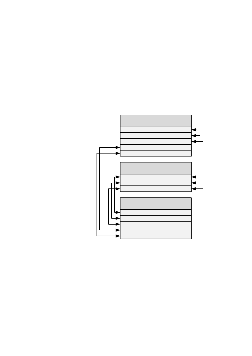
Description
The LSG Series file system can save files to
internal memory (Media | Memory) and external
memory (Media | USB).
To save or recall Memory, Setup or Preset data,
the LSG Series uses a three tier system where
files are saved or recalled in the following order:
Active settings <> Internal memory <> USB.
This can be best described in the picture below.
Local Memory
Media | Memory
Media | USB
Memory data
Setup data x1
Nseq. data x1
Fseq. data x1
Preset data x1
Memory data (M001 ~ M256)
Setup data (001 ~ 100)
Preset data (P0 ~ P9)
Memory data (M001 ~ M256)
Setup data (001 ~ 100)
Nseq. data x1
Fseq. data x1
Preset data (P0 ~ P9)
Active Settings
Memory data x1
For example:
To load Preset Data P7 from USB, you must first
load Preset Data P0~P9 to internal memory,
then from internal memory load Preset P7 to be
the active preset setting.
For normal and fast sequences however, files
can be saved or recalled directly to/from USB
memory.
2-8. Save Recall
The LSG Series can save and recall system settings, preset data,
memory data, Go-NoGo settings as well as normal and fast
sequences to internal memory or to USB.
2-8-1. File Structure
57

Memory Data
Memory data contains general settings and is
used for creating programs. Memory Data
contains the operating mode, range, response
and Go/NoGo settings. Memory data can be
stored both internally and externally to USB.
Preset data and Memory data store the same
contents.
Internal Format
M001 ~ M256
External Format
model no_file no.M
example: 3021_01.M
Setup Data
Setup data contains all general configuration
settings, protection settings, program and
program chain settings, as well as parallel
configuration settings.
Internal Format
1 ~ 100
External Format
model no_file no.S
example: 3021_00.S
Preset Data
Preset Data contains the same settings as the
Memory Data. Preset Data contains the
operating mode, range, response and Go-NoGo
settings.
Internal Format
P0 ~ P9
External Format
model no_file no.P
example: 3021_00.P
NSeq Data
NSeq Data contains the Normal Sequence
settings.
Internal Format
None
External Format
model no_file no.N
example: 3021_00.N
FSeq Data
FSeq Data contains the Fast Sequence settings.
Internal Format
None
External Format
model no_file no.F
example: 3021_00.F
Description
When saving Memory, Setup or Preset Data to
internal memory, the currently active setting is
saved to one of the internal memory slots.
Memory Data has 256 memory slots, Setup Data
has 100 memory slots and Preset Data has 10
memory slots.
2-8-2. File Types
2-8-3. Saving Files to Internal Memory
58
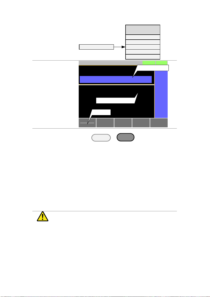
Memory Data
Example
Active setting
M001
:
:
M256
MXXX
Media | Memory
Display
Save
Data Type Memory
RS232
31/Oct/2013
Memory M256
A Value
CC
0.35A
15V
Static
LOAD
Media
Memory
Recall
Memory
Save file location
Save file type
File
Utility
Operation
1. Press
Shift
+
File
FUNC
.
2. Select Memory with the Media[F1] soft-key.
3. Select the Data Type and choose the type of file
to save.
Data Type:
Memory Data, Setup Data,
Preset Data
4. Select which internal memory location to save
the file.
Memory:
Setup Memory:
Preset:
M001 ~ M256
1 ~ 100
P0 ~ P9
5. Press Save[F3] to save.
Save Ok will be displayed when the
save has been completed.
Note
Normal Sequence and Fast Sequence data
cannot be recalled from or saved to an internal
memory slot.
Description
When saving files to USB memory, all the
memory locations from the selected data type
are saved as a single file to the USB file path
directory.
2-8-4. Saving Files to USB Memory
59
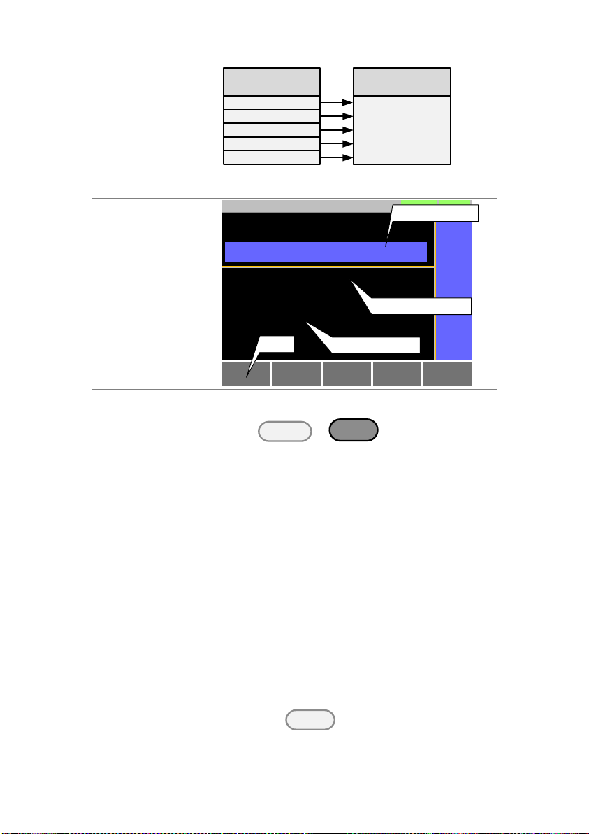
Memory Data
Example
Save file
Media | USB
M001
:
:
M256
MXXX
Media | Memory
For example, Memory Data M001 to M256 are
saved to a single file on USB.
Display
Save
Data Type Memory
RS232
31/Oct/2013
Save File 3021_01.M
A Value
CC
0.35A
15V
Static
LOAD
Media
USB
Recall
USB
Save file type
3021_02.MRecall File
Path: usb:
Save file name
USB file path
File
Utility
Operation
1. Insert a USB drive into the USB port.
2. Press
Shift
+
File
FUNC
.
3. Select USB with the Media[F1] soft-key.
4. Select the Data Type and choose the type of file
to save.
Data Type:
Memory Data, Setup Data,
Preset Data, NSeq, FSeq
5. Select Save File and choose a save filename.
Turn the scroll wheel to
increase/decrease the file number.
Memory:
Setup Memory:
Preset:
NSeq:
FSeq:
Model_file number.M
Model_file number.S
Model_file number.P
Model_file number.N
Model_file number.F
6. Press Save[F3] to save.
The file will be saved to the USB file path.
Save Ok will be displayed when the save has
been completed.If saving-over an existing file
you will be asked to confirm the save.
Press the
Enter
key to confirm.
60
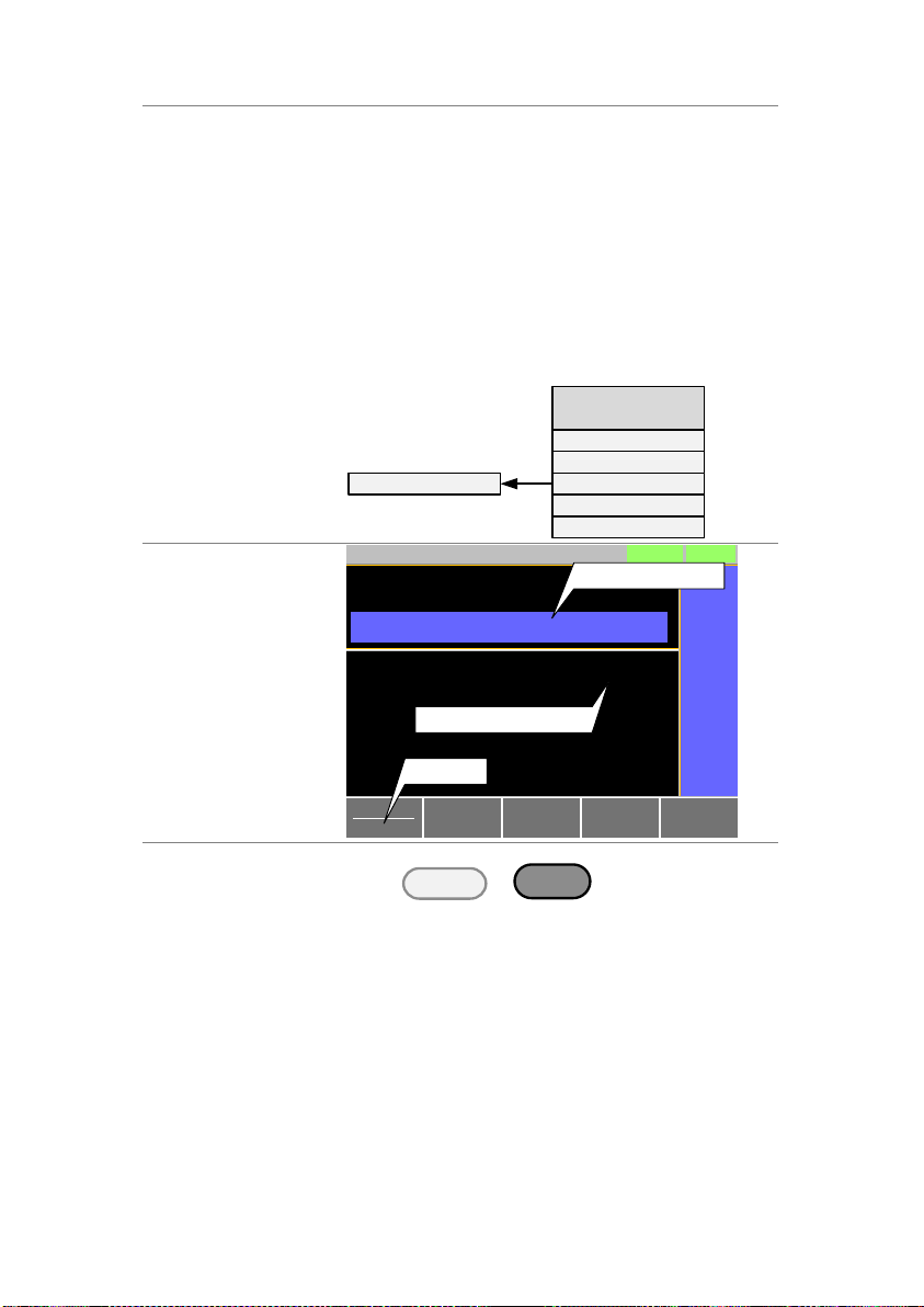
File Utilities
Press File Utility[F5] to access the file utility. See
page 63 for details.
Change the USB path.
Rename files or create directories.
Description
When recalling Memory, Setup or Preset Data
from the internal memory slots, the recalled file
becomes the active setting.
Memory Data has 256 memory slots, Setup Data
has 100 memory slots and Preset Data has 10
memory slots.
Memory Data
Example
Active setting
M001
:
:
M256
MXXX
Media | Memory
Display
Save
Data Type Memory
RS232
31/Oct/2013
Memory M256
A Value
Fine
CC
0.35A
15V
Static
LOAD
Media
Memory
Recall
Memory
Save file location
Save file type
Operation
1. Press
Shift
+
File
FUNC
.
2. Select Memory with the Media[F1] soft-key.
3. Select the Data Type and choose the type of file
to recall.
Data Type:
Memory Data, Setup Data,
Preset Data
4. Select which memory slot to recall from.
Memory:
Setup Memory:
Preset:
M001 ~ M256
1 ~ 100
P0 ~ P9
2-8-5. Recalling Files from Internal Memory
61

5. Press Recall[F4] to recall.
For Memory Data and Preset Data, a popup
window will appear. Press the
Enter
key to
confirm the recall.
Note
Normal Sequence and Fast Sequence data
cannot be recalled from or saved to an internal
memory slot. They can, however, be recalled
directly from USB memory. See the next section
below for details.
Description
When recalling Memory, Setup or Preset files
from USB memory, a single file from the USB
drive will overwrite all the existing memory slots
for the selected data type.
For Normal or Fast Sequence files, the recalled
file becomes the active setting as these types of
files don’t have an internal memory slot.
Caution
You can only recall files from the same model.
Memory Data
Example
Media | USBMedia | Memory
Recall file
M001
:
:
M256
MXXX
For example, if the file 3021_01.M is recalled, all
the Memory Data from M001 to M256 will be
overwritten.
Display
Save
Data Type Memory
RS232
31/Oct/2013
Save File 3021_01.M
A Value
Fine
CC
0.35A
15V
Static
LOAD
Media
USB
Recall
USB
Save file
type
3021_02.MRecall File
Path: usb:
Save file
name
USB file
path
File
Utility
2-8-6. Recalling Files from USB Memory
62

Operation
1. Insert a USB drive into the USB port.
2. Press
Shift
+
File
FUNC
.
3. Select USB with the Media[F1] soft-key.
4. Select the Data Type and choose the type of file
to recall.
Data Type:
Memory Data, Setup Data,
Preset Data, NSeq, FSeq
5. Select Recall File and choose a filename.
Turn the scroll wheel to increase/decrease the
file number.
Memory:
Setup Memory:
Preset:
NSeq:
FSeq:
Model_file number.M
Model_file number.S
Model_file number.P
Model_file number.N
Model_file number.F
6. Press Recall[F4] to recall.
Recall Ok will be displayed when the recall has
been completed.
File Utilities
Press File Utility[F5] to access the file utility. See
page 63 for details.
Change the USB path.
Rename files or create directories.
Caution
If “Machine Type Error” is displayed it indicates
that the file that you are trying to recall originated
from a different model. You can only recall files
from the same model.
Description
By default when you try to recall a file or setting
from memory, a message will appear asking you
to press the Enter key to confirm. This is the
standard safety measure to ensure that the
wrong file/setting is not recalled. This safety
measure can be disabled by setting the Mem.
Recall setting to “Direct”.
Operation
1. Press
Main
> Configure[F5] > Other[F2] and
set the Mem. Recall setting.
Range:
Safety, Direct
Description
The file utility allows you to create new folders,
rename files and set the USB path directory.
It is only available for use with the USB external
memory.
2-8-7. Recall Memory Safety Setting
2-8-8. File Utility
63

Display
Select Rename
Previous
Menu
LOADRS232
31/Oct/2013
Path: usb:\Test
3 folder(s), 15 file(s)
New
Folder
Delete
Folder1
Folder2
Folder3
3021_01.M
3021_01.M
3021_01.M
16-Feb-12 13:46
18-Feb-12 11:16
19-Feb-12 08:32
01-Mar-12 10:12
03-Mar-12 13:13
23-Mar-12 09:02
USB path
cursor
Access the File
Utilities Menu
1. Insert a USB drive into the USB port.
2. Press
Shift
+
File
FUNC
> File Utility[F5].
The file utilities screen appears.
Create a new
Folder
1. Press New Folder[F2] to create a new folder.
Use the on-screen display to enter the
filename.
A maximum of 8 characters.
Rename a
Folder
1. Use the scroll wheel to move the cursor to the
file/folder you wish to rename.
2. Press Rename[F3].
Use the on-screen display to enter the ilename.
A maximum of 8 characters.
Delete File or
Folder
1. Use the scroll wheel to move the cursor to the
file/folder you wish to delete.
2. Press Delete[F4].
3. Press Delete[F4] again to confirm the deletion.
Description
The current settings can be saved to P0 ~ P9
using the Preset key and the number pad.
Operation
1. Press
Preset
and hold
P0
0
~
P9
9
until a beep is heard.
The beep indicates that the setting was saved
to the selected preset.
2-8-9. Preset
The Preset key is used to save and recall preset settings from the
front panel quickly. The presets have the same contents as memory
data, this includes the operating mode, range, configuration settings
and Go-NoGo settings.
2-8-9-1. Quick Preset Save
64

Description
Presets P0 to P9 can be recalled quickly by
using the Preset key and the number pad.
Operation
1. Press
Preset
+
P0
0
~
P9
9
.
2. Press
Enter
to confirm the recall when a
popup window appears.
3. Press
Preset
again to deactivate the preset
key.
Description
The factory default settings can be recalled at
any time. See page 127 for a list of the factory
default settings.
Operation
1. Press
Shift
+
File
FUNC
.
2. Select Default with the Media[F1] soft-key.
3. Press Factory Default[F2].
4. Press Factory Default[F2] again to confirm.
Description
The currently active settings can be set as the
“User’s Default” settings.
Save User’s
Default Setting
1. Press
Shift
+
File
FUNC
.
2. Select Default with the Media[F1] soft-key.
3. Press Save[F3].
The User’s Default is saved immediately.
Recall User’s
Default Setting
1. Press
Shift
+
File
FUNC
.
2. Select Default with the Media[F1] soft-key.
3. Press Recall[F4].
4. Press Recall[F4] again to confirm.
A User’s Default must be saved first before it
can be recalled.
2-8-9-2. Quick Preset Recall
2-8-10. Default Settings 2-8-10-1. Factory Default Settings
2-8-10-2. User’s Default Setting
65

Description
The Function Select option is used to turn a
Program, Normal Sequence, Fast Sequence or
OCP function on or off. Before one of these
functions are turned on, they should be
configured beforehand. Sequences or the OCP
function, respectively.
Function Select
Screen
Program
Fast
Sequence
PROG
RS232
31/Oct/2013
Normal
Sequence
OCP
Function Select
FUNCTION
Complete Ring Time
NSEQ Timer Elapsed
5 s
PROG
Operation
1. Press
File
FUNC
.
2. Select Function Select and choose a
function to turn on or choose to turn off
the last function.
Range
OFF, PROG, NSEQ, FSEQ, OCP
Note
After a function is selected, it is then
“turned on”.
PROG , NSEQ , FSEQ or OCP will
appear at the top of the display when the
selected function is on.
3. Function MENU
3-1. Function Menu Overview
The Function menu can be used as a quick access hub to the
Program, Normal Sequence, Fast Sequence or OCP menus. It
is also used to set Function specific settings:
Function Select.
Complete Ring Time.
NSEQ Timer.
3-1-1. Select a Function
66

When in the Main menu, the PROG,
NSEQ,FSEQ or OCP icon will appear
prominently on the display to remind the
operator that a function is still on. A
normal load cannot be turned on when a
Function mode is turned on.
Be sure to turn the selected function off
to return to normal operation.
Description
When a function is turned on, the load can be
turned on (with the selected function) by
pressing Shift + Load.
The Load key will turn orange when the load is
“on”.
The load can be turned off again by pressing
the Load key.
Description
The Complete Ring Time function turns the
alarm on for a user-set amount of time after a
program, sequence or OCP function has
finished.
Function Select
Screen
Program
Fast
Sequence
PROG
RS232
31/Oct/2013
Normal
Sequence
OCP
Function Select
FUNCTION
Complete Ring Time
NSEQ Timer Elapsed
5 s
PROG
Operation
1. Press
File
FUNC
.
2. Select Complete Ring Time and select
how long the alarm should ring after a
function has completed.
Range
OFF, 1 – 600s, Infinity (Default:off)
3-1-2. Turning on the Load with the Selected Function
3-1-3. Complete Ring Time
67
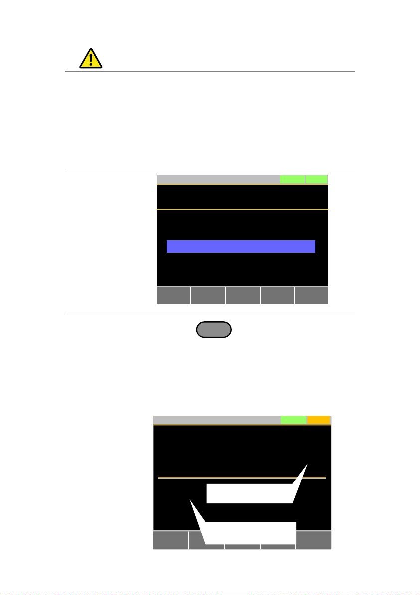
Note
The alarm may not sound if Alarm Tone is
turned off in the Utility>Other menu.
Description
The NSEQ Timer setting determines whether
the timer for the Normal Sequence function
displays the elapsed time or the remaining
time for both the current step and the overall
test time for the sequence.
Function Select
Screen
Program
Fast
Sequence
PROG
RS232
31/Oct/2013
Normal
Sequence
OCP
Function Select
FUNCTION
Complete Ring Time
NSEQ Timer Elapsed
5 s
PROG
Operation
1. Press
File
FUNC
.
2. Select NSEQ Timer and select whether
the current step and total test time is
displayed as elapsed time or remaining
time.
Range
Elapsed, Remaining
(Default: Elapsed)
Display example
Continue
NSEQRS232
31/Oct/2013
Run N.Seq.
0.000
V
0.000
A
0.00
w
Step
Seq. No: 01
Loop: 0001
0003
0:00:05
0:00:05
Elapsed or remaining
time for the current step
Elapsed or remaining time
for the total test time
3-1-4. NSEQ Timer
68

Note
When the total test time is >1000 hours, then
the total test time will always be displayed as
the elapsed time.
Description
When you run a program, you are essentially
executing up to 16 different load operations
consecutively. Each of the different load
operations are “steps” in the program. A program
starts at step 01 and ends at step 16.
A program recalls the operating mode, range,
static/dynamic mode, response speed and
other settings of each step from stored
memory. It also recalls the Go-NoGo settings.
The same memory settings can be used for
multiple steps.
The execution time of each step is
configurable.
Applies the Go-NoGo settings for each step.
Each step must be executed in order.
Each step can be configured to automatically
go to the next step or wait for confirmation from
the user before proceeding to the next step.
Individual steps can be skipped.
Programs can be linked together to make
program chains.
Program chains need not be executed in order.
There are 16 steps to a program.
There are up to 16 programs to a chain.
3-2. Program
The LSG Series can create programs that are designed to stepthrough up to 16 pre-set load operations. The program function is a
powerful tool that can allow you to perform a number of different
operations in succession.
The execution time of each step is user-defined.
Programs can be chained together to make larger programs.
Up to 16 programs can be created for a program chain.
See page 57 for saving load operations.
3-2-1. Program Overview
69
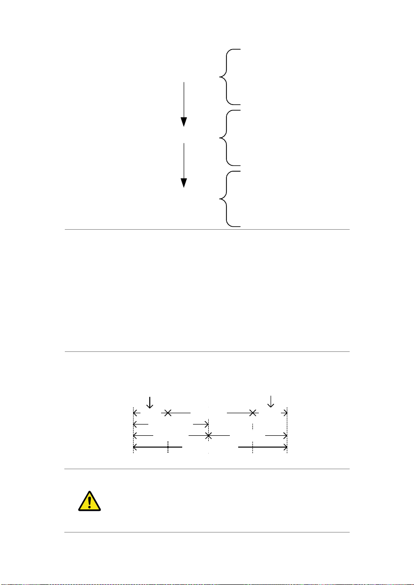
PROGRAM 1
STEP 01
STEP 02
:
STEP 16
PROGRAM 2
STEP 01
STEP 02
:
STEP 16
PROGRAM 3
STEP 01
STEP 02
:
STEP 16
Setting
Overview
A program contains the following settings for
each step:
Memory: the memory location of the load
operation for the selected step (M001~M256).
Run: Designates the run setting for the step
(Auto, Manual, Skip).
On-Time: Sets the run time of the test.
Off-Time: Sets the off time between steps.
P/F-Time: Sets the testing pass/fail delay time
for GoNo Go testing.
Short-Time: Sets the shorting time for the step,
if any.
Timing
Diagram for
Single Step
Below is a timing diagram of a single step in a
program.
On-Time Off-Time
Step test time
Start of Step End of Step
P/ F End Test Time (fixed)
P/ F Time
0.04s
0.06s
Short-Time
P/ F Start Test Time (fixed)
Note
Before creating a program, the settings for each
step must first be created and saved to internal
memory (M001~M256). See the save recall
chapter for further details, page 57.
3-2-2. Create a Program
70
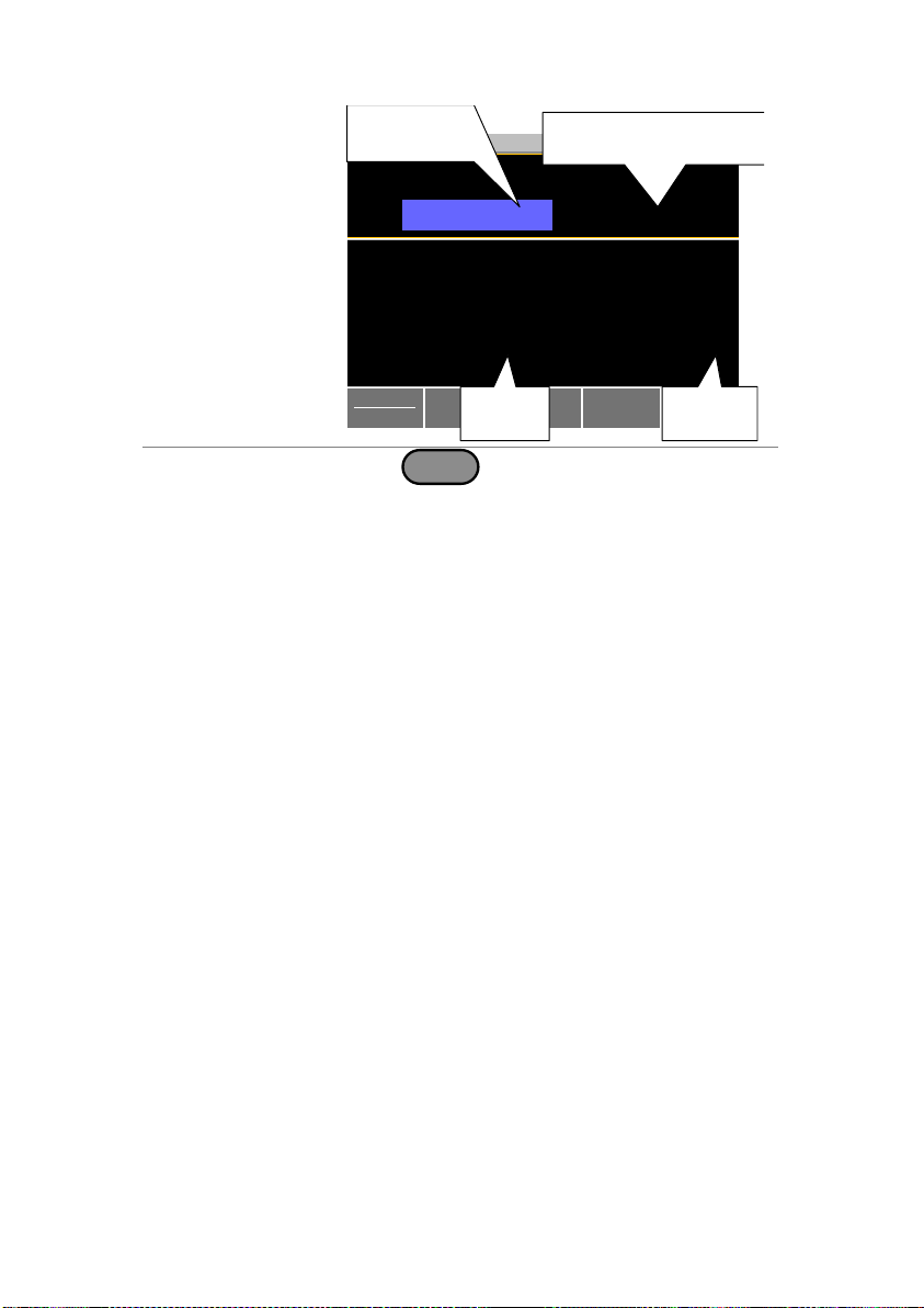
Program
Setting Display
Overview
Chain
Previous
Menu
LOADRS232
03/09/12
Timing Edit for Program
On-Time:
Run:
Memory
0.1
Skip
M001
Short-Time:
P/F-Time:
Off-Time:
Off
Off
Off
STEP: 01
Program
Off
Recall
Default
Program
number
Step number in
selected program
Program
settings
PROG: 01
Program
settings
Operation
1. Press
FUNC
> Program[F1].
Note that Program[F1] is off by default.
2. Select PROG and select a program number to
edit.
PROG
01 ~ 16
3. Select a STEP in the selected program.
STEP
01 ~ 16
4. Select Memory and select which memory
location to load for the selected step.
Settings loaded from the memory location will
be used for the selected step.
The same memory location can be used for
multiple steps.
Memory
M001 ~ M256
5. Set the Run setting for the step.
By default RUN is set to Skip.
The Auto setting will automatically start and go
onto the next step.
The Manual setting will wait for the user to
press Next[F2] before running the step.
Run
Skip, Auto, Manual
6. Choose the On-Time in seconds.
The on-time setting determines how long the
load is turned on for the selected step.
The on-time is defined as the total test time
minus the off-time.
On-Time
0.1 ~ 60 seconds
71

7. Choose the Off-Time in seconds.
The off-time setting determines how long the
load is turned off between the end of the
current step and the start of the next step.
The off-time is defined as the total test time
minus the on-time.
Off-Time
Off, 0.1 ~ 60 seconds
8. Choose the P/F-Time (pass/fail time) in seconds.
The P/F-Time refers to the P/F delay time. This
delay time includes the 0.06 P/F start test time,
as shown in the timing diagram on page 70.
P/F-Time
Off, 0.0 ~ 119.9 seconds
9. Set the Short-Time in seconds.
Has the same action as pressing the short key.
See page 36 for details about shorting the load.
Short-Time
Off, 0.1 seconds ~ On-Time
10. Repeat steps 3 to 9 for all the steps in the
program.
A maximum of 16 steps per program can be
created.
Steps that are not configured are set to “Skip”
by default.
11. Press Save[F3] to save the program and all the
steps in the program.
The program will be saved to internal memory.
See the Save/Recall chapter on details on how
to save to Setup memory.
Recall Default
Pressing Recall Default[F4] will recall the default
settings for each program/step. See page 127
for details.
72
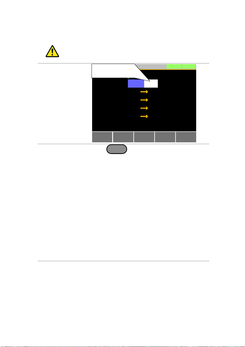
Note
Before creating a program chain, make sure a
number of programs have already been saved.
These will be used to create the program chain.
Chain Setting
Display
Overview
Select
Start
LOADRS232
03/09/12
Off
P03 Off
P02 Off
P04
P01
Start
Off
P01
Program Chain Set
Starting program
for the chain
Recall
Default
Previous
Menu
Operation
1. Press
FUNC
> Program[F1] > Chain[F2].
It may be necessary to load the programs from
Setup memory if they were not created in the
current session.
2. If Start is not already selected, press Select
Start[F1] and select which program will be used to
start the program chain.
Start:
P01 ~ P16
3. Select P01 and choose which program will be
linked to P01.
Selecting OFF will end the chain after P01.
Selecting P01 will create an infinite chain.
Chains need not be linked in sequential order.
P01:
OFF, P01 ~ P16
4. Repeat step 3 for any remaining programs in the
chain.
5. Press Save to save the program chain to internal
memory.
Pressing Recall Default[F4] will reset the chain to
the default settings. See page 127 for details.
Recall Default[F4] will essentially clear the
program chain.
3-2-3. Create a Program Chain
73
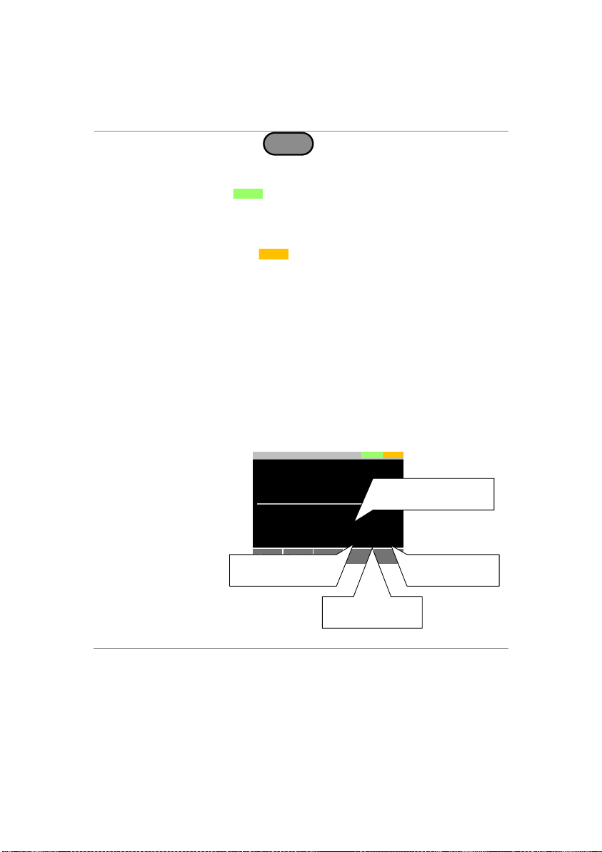
Description
A program or program chain is run the same way
as a normal load.
Operation
1. Press
FUNC
> Program[F1].
2. Turn program mode on by setting Program[F1]
to On.
PROG
will appear at the top of the display when
Program is On.
3. Turn the load on.
The program/chain starts immediately.
The
PROG
icon turns orange when the load is
turned on.
4. When a program/chain is running the screen
displays which program, step and memory is
currently active.
Press Pause[F1] to suspend a test, press
Continue[F1] to resume.
Press Next[F2] to run the next step if its Run
setting was set to Manual.
5. When a program/chain has finished running, a
list of the Go-NoGo results for each step are
displayed.
Press Exit[F5] to exit.
Display:
Program/Chain
Running
Pause
PROGRS232
03/09/12
Step(Memory)
Program No:
01(001)
01
Run Program
GO
0.000
V
0.000
A
0.00
w
Next
Step that is
currently running.
Program number that
is currently running.
Memory number
of current step.
Go-NoGo result
for the step
3-2-4. Running a Program or Chain
74

Display:
Program/Chain
Finished
Exit
PROGRS232
31/Oct/2013
Run Program Detail Result
1
1
1
Program
3
2
1
Step
NG
GO
GO
Result
Description
A normal sequence is comprised of a user-defined
number of steps that when executed in sequence can
be used to simulate a DC load.
・Up to 1000 discrete steps can be configured using
normal sequences.
・Each normal sequence can have a memo note
attached to it
・Normal Sequences can be looped up to 9999 discrete
times or for an infinite amount of times.
・Normal sequences can be configured to hold a set
voltage, current, power or resistance at the end of the
load.
・Normal Sequences can be linked together in a chain.
3-3. Sequence
The LSG Series supports both programs and sequences. The
essential difference between programs and sequences is that
programs can use different operating modes for each step while
sequences use the same operating mode throughout the whole
sequence. In effect sequences are used to create complex load
simulations.
There are two different types of Sequences, Normal Sequences and
Fast Sequences.
Normal sequences can define the execution time and slew rate of
each step.
On the other hand the execution time for each step in a fast
sequence is fixed to the rate (Time Base setting) set by the user.
3-3-1. Normal Sequence Overview
75
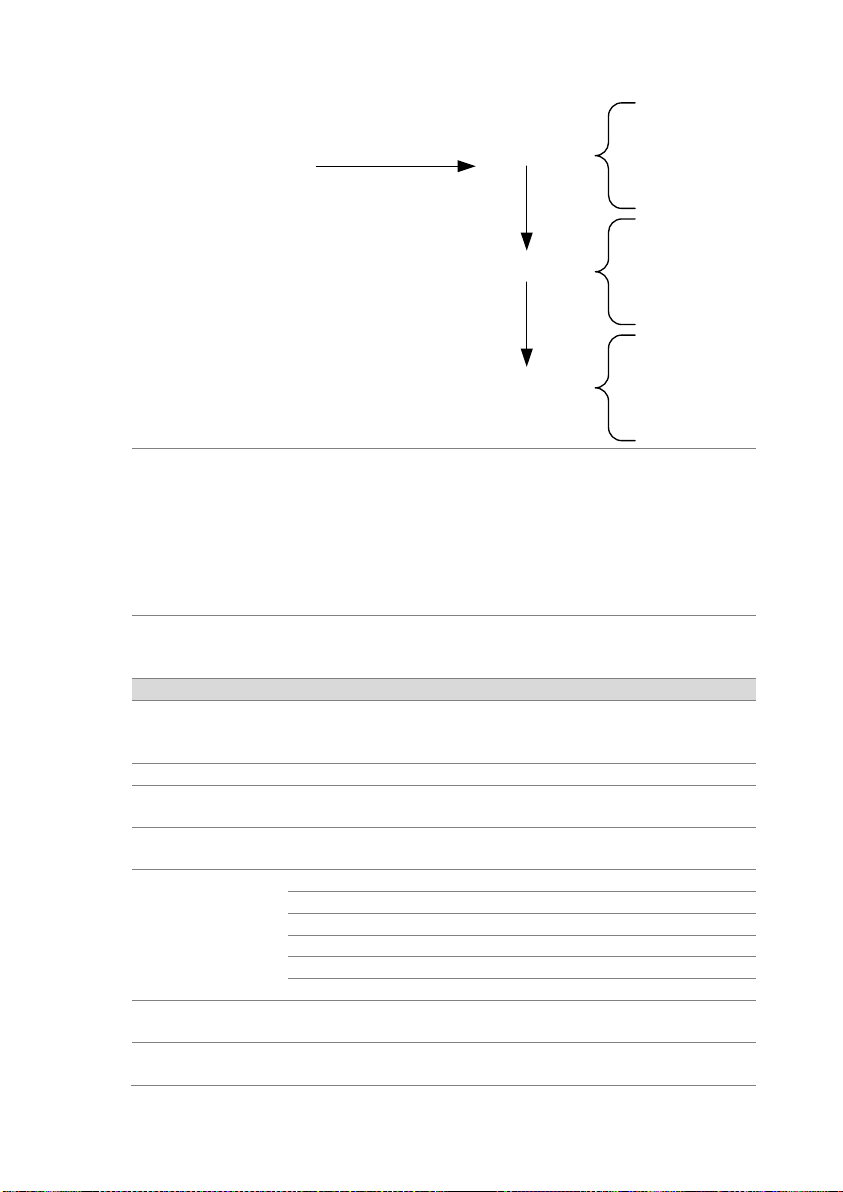
Sequence 1
STEP 01
STEP 02
:
STEP N
Sequence 2
STEP 01
STEP 02
:
STEP N
Sequence 10
STEP 01
STEP 02
:
STEP N
Start Sequence
:
:
:
:
Description
Normal Sequence configuration is split into Timing
Edit configuration and Data Edit configuration.
Timing Edit configuration is used to configure the
actual sequences, such as mode, range, loops and
chains.
Data Edit configuration is used to create the actual
steps used in each sequence.
See below for a description of each.
Timing Edit
Overview
A Normal Sequence contains the following timing
settings for each sequence:
Setting
Setting Range
Description
Start
S01 ~ S10
Sets which sequence are used to
start a chain of Normal
Sequences.
Seq.No
S01 ~ S10
Sets the current sequence to edit.
Memo
12 characters
A user-created note for the
currently selected sequence.
Mode
CC, CR, CV, CP
Operating mode for the sequence.
+CV mode is supported.
Range
ILVL
Low I range, low V range
IMVL
Middle I range, low V range
IHVL
High I range, low V range
ILVH
Low I range, high V voltage range
IMVH
Middle I range, high V range
IHVH
High I range, high V range
Loop
Infinite,
01 ~ 9999
Sets the amount of times to loop
the selected sequence.
Last Load
OFF, ON
Set the load condition after the
end of the sequence.
76
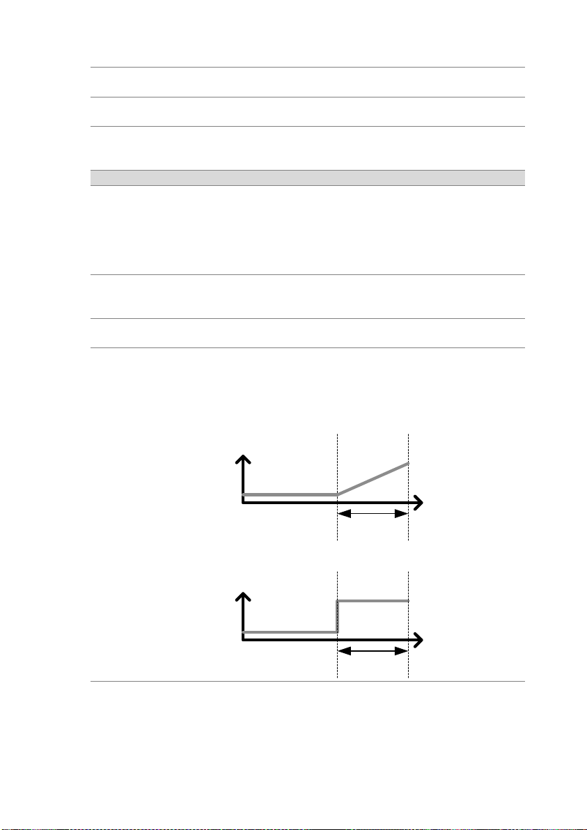
Last
Value
The setting value of the load for
when Last Load = ON.
Chain
Off, S01~S10
Sets the next sequence in the
chain, when not set to off.
Data Edit
Overview
Each step in a normal sequence contains the
following setting parameters:
Setting
Setting Range
Description
Step
0001 ~ 1000
Selects/displays the current step
in the sequence.
・The number of available steps is
dependent on the number of
steps added using the Insert
Point[F1] functions.
Value
The current, voltage, power or
resistance setting for the
selected operating mode.
Load
ON, OFF
Turns the load on or off for the
selected step.
RAMP
ON, OFF
When turned on the current
transition is evenly ramped from
the start of the step to the end of
the step. When turned off the
current transition is stepped.
Time
amplitude
Step time
Ramp = On
Time
amplitude
Step time
Ramp = Off
TRIG OUT
ON, OFF
When TRIG OUT is set to ON, a
trigger signal is output from the
TRIG OUT BNC terminal at the
start of the step. See page 113
for details.
77

Time
amplitude
TRIG OUT = ON
TRIG OUT
Start of
step
PAUSE
ON, OFF
Pause: Inserts a pause at the
end of the sequence. When
paused, the unit will pause at the
end of step
current/voltage/resistance/power
level. The sequence can be
resumed by pressing Next[F2] or
by using an external trigger
signal (page 111).
Edit Timing
Display
Previous
Menu
LOADRS232
03/09/12
Timing Edit for Normal Sequence
Loop:
Range:
Mode:
Infinity
ILVL
CC
Chain:
Last
Last Load:
Off
0.00000 A
OFF
Seq.No: S01
N. Seq.
Off
Edit
Sequence
Start sequence
Start S01
Memo: No Memo
Sequence number
Sequence settings
Operation
1. Press
FUNC
> Normal Sequence[F2].
Note that N. Seq.[F1] is off by default.
Select Start and select the number of the starting
sequence.
Start:
S01 ~ S10
2. Select a Seq. No. and select which sequence to edit.
Seq. No.:
S01 ~ S10
3-3-2. Timing Edit Configuration
78
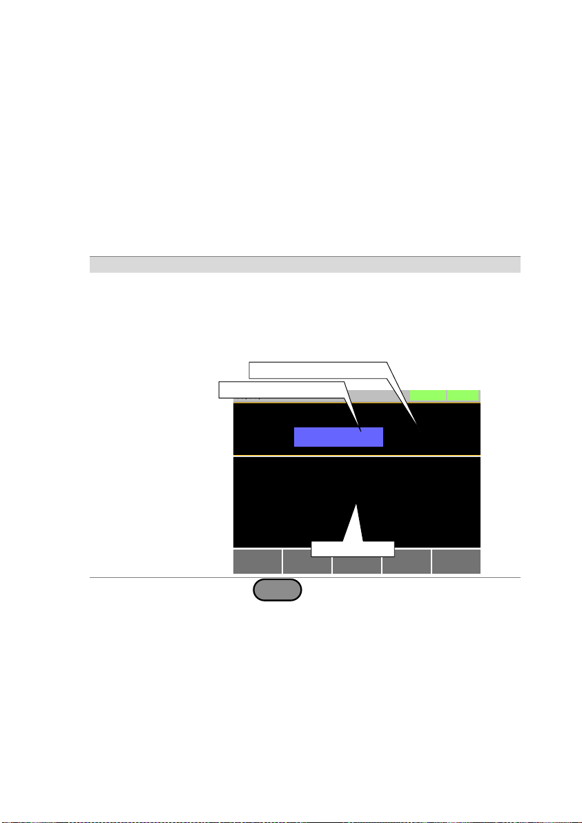
3. Set the following parameters for the currently selected
sequence. See page 75 for details on each parameter.
Memo
Mode
Range
Loop
Last Load
Last
Chain
4. Press Save[F3] to save the timing settings for the
currently selected sequence.
Sequence Timing configuration is complete.
Go to Data Edit to edit the steps used in the Normal
Sequences. See page 79.
Go to Running a Normal Sequence to run the normal
sequence. See page 80.
Data Edit
Display
Previous
Menu
LOADRS232
03/09/12
Data Edit for Normal Sequences
RAMP:
LOAD:
OFF
OFF
000 H:
PAUSE:
TRIG OUT
OFF
OFF
001ms
0001
Insert
Point
Save
Step: 0001
Time:
Value: 0.00000 A
/
00 M: 00 S.
Delete
Point
Active step number
Total number of steps
Step settings
Operation
1. Press
FUNC
> Normal Sequence[F2].
2. Select Seq.No. and select the sequence you wish to
edit.
Start:
S01 ~ S10
3. Press Edit Sequence [F2] to enter the Data Edit
configuration menu.
Note that when there no steps in the current
sequence the Data Edit for Normal Sequence
settings are blank.
4. Press Insert Point[F1] to add a step to the sequence
after the current step.
Every time Insert Point is pressed the Step
3-3-3. Data Edit Configuration
79

parameter is incremented.
The inserted point becomes the current step.
5. Set the following parameters for the currently selected
step. See the Data Edit Overview on page 77 for
configuration details.
Value
Time
LOAD
RAMP
TRIG OUT
PAUSE
6. If you wish to edit a previously inserted point/step, use
the Step parameter.
Steps can only be selected after they have already
been inserted.
Steps
0001 ~ 1000
7. The currently selected step can be deleted using the
Delete Point[F2] function.
8. After all the steps for the sequence are complete,
press Save[F3] to save the steps.
Data Edit for Normal Sequence configuration is
complete.
Go to Timing Edit for Normal Sequences to edit the
sequence. Page 78.
Go to Running a Normal Sequence to run the normal
sequence. Page 80.
Description
A load created with the Normal Sequence
function is run the same way as a normal load.
Operation
1. Press
FUNC
> Normal Sequence [F2].
2. Turn normal sequence mode on by setting
N. Seq.[F1] to On.
NSEQ
will appear at the top of the
Display when N. Seq. is On.
3. Turn the load on.
The normal sequence/chain starts immediately.
The
NSEQ
icon turns orange when the load is
turned on.
3-3-4. Running a Normal Sequence
80

4. When a normal sequence/chain is running, the
screen displays which sequence, step and loop
are currently active.
Sequences can be paused by pressing
Pause[F1] and resumed again by pressing
Continue[F1].
If no steps have been created “No
N.Seq.” will be displayed on the screen.
“Sequence Complete” will be displayed at the
end of the sequence.
Display:
Sequence/Chain
Running
Continue
NSEQRS232
31/Oct/2013
Run N.Seq.
0.000
V
0.000
A
0.00
w
Step
Seq. No: 01
Loop: 0001
0003
Description
A fast sequence is comprised of a user-defined
number of steps that can be executed at a high
frequency. Unlike normal sequences, each step
in a fast sequence has the same execution time
(time base).
This mode is only available for CC and CR
mode.
Up to 1000 discrete steps can be configured
using fast sequences.
Each fast sequence can have a memo note
attached to it.
Fast Sequences can be looped up to 9999
discrete times or for an infinite amount of
times.
Fast sequences can be configured to hold a
set current or resistance at the end of the load.
No ramping function can be used with the Fast
Sequence function.
3-3-5. Fast Sequence Overview
81

Fast Sequence
STEP 01
STEP 02
:
STEP N
Loop:
Description
Fast Sequence configuration is split into Timing
Edit configuration and Data Edit configuration.
Timing Edit configuration is used to configure all
the settings that are common to all the steps of
the fast sequence. This includes settings such
as the mode, range, loops and time base.
Data Edit configuration is used to create the
actual steps used in each sequence.
See below for a description of each.
Timing Edit
Overview
A Fast Sequence contains the following timing
settings for each sequence:
Setting
Setting Range
Description
Memo
12 characters
A user-created note for the
currently selected
sequence.
Mode
CC, CR
Operating mode for the
sequence.
Range
ILVL
Low I range, low V range
IMVL
Middle I range, low V range
IHVL
High I range, low V range
ILVH
Low I range, high V voltage
range
IMVH
Middle I range, high V
range
IHVH
High I range, high V range
Loop
Infinity,
01 ~ 9999
Sets the amount of times to
loop the selected
sequence.
Last Load
OFF, ON
Set the load condition after
the end of the sequence.
Last
0.000000
The load setting for when
Last Load is set to ON.
RPTSTEP
0001 ~ 1000
Last step number
(0001~1000) per loop
82

Time Base
0.025 ~600ms
Sets the step execution
time.
Data Edit
Overview
Each step in a fast sequence contains the
following setting parameters:
Setting
Setting Range
Description
Step
0001 ~ 1000
Selects/displays the current
step in the sequence.
The number of available
steps is dependent on the
number of steps added
using the Ins. Point[F1]
functions.
A minimum of 3 steps.
Value
The current or resistance
setting for the selected
operating mode.
TRIG OUT
ON, OFF
When TRIG OUT is set to
ON, a trigger signal is
output from the TRIG OUT
BNC terminal at the start of
the step. See page 113 for
details.
Time
amplitude
TRIG OUT = ON
TRIG OUT
Start of
step
FILL Overview
The FILL function is used to evenly step up the
current or resistance value settings from a
starting step to a finishing step.
The Fill Function can be used before or after
points are added to the fast sequence.
Before: Will pre-fill each value within the fill
range when a new step is added.
After: Will post-fill each value within the fill
range.
83
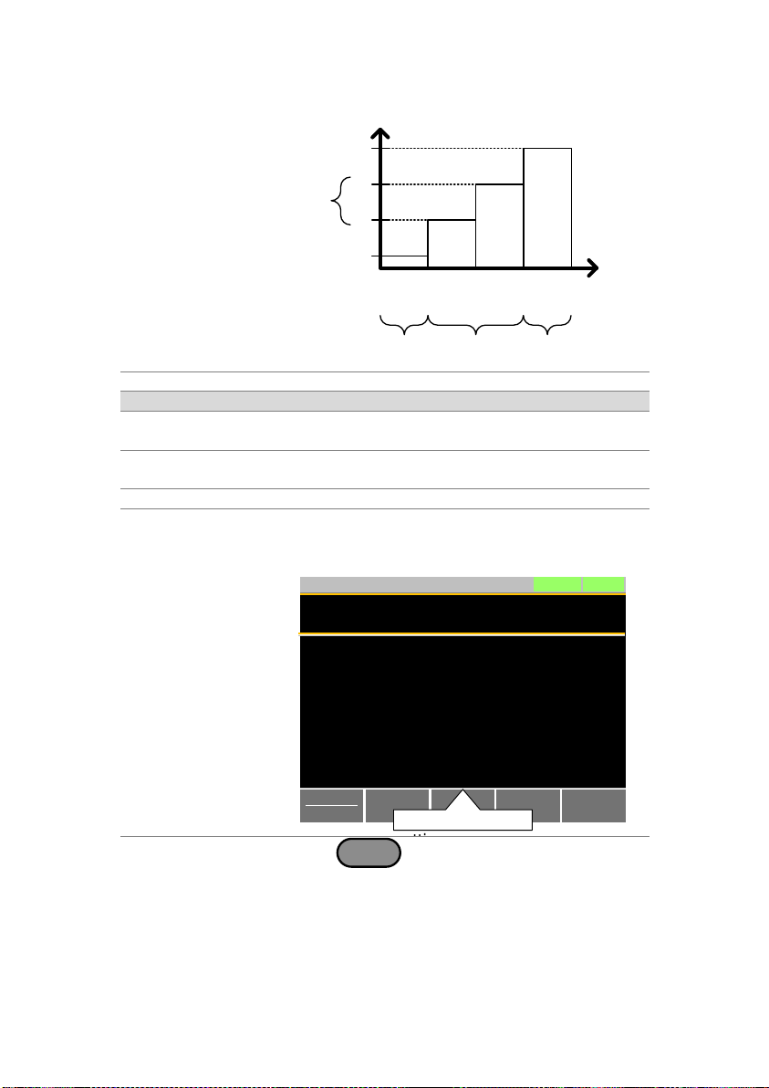
Value setting
Step
02
Step
4
Step
01
Step
FILL example
Step
03
End_Value
Start_Value
Filled
values
Filled steps
Start_Step
End_Step
Setting
Setting Range
Description
Start_Value
Sets the current or resistance
value for the starting step.
End_Value
Sets the current or resistance
value for the ending step.
Start_Step
0001 ~ 1000
Sets the starting step number.
End_Step
0001 ~ 1000
Sets the ending step number.
Edit Timing
Display
Previous
Menu
LOADRS232
31/Oct/2013
Timing Edit for Fast Sequence
Loop:
Range:
Mode:
Infinity
ILVL
CC
RPTSTEP
Last
Last Load:
0004
0.00000 A
OFF
F. Seq.
Off
Edit
Sequence
Memo: 001
Sequence
Time Base: 600.00 ms
Operation
1. Press
FUNC
>Fast Sequence[F3].
Note that F. Seq.[F1] is off by default.
3-3-6. Timing Edit Configuration
84
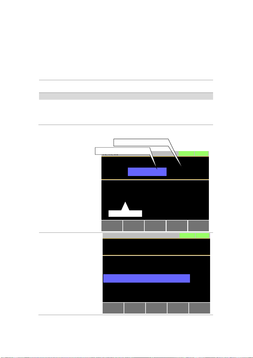
2. Set the following parameters for the fast
sequence. See page 81 for details on each
parameter.
Memo
Range
Time Base
Last
Mode
Loop
Last Load
RPTSTEP
Save
Press Save[F3] to save the timing settings for
the fast sequence.
Sequence Timing configuration is complete.
Go to Data Edit to edit the steps used in the
Fast Sequence. Page 85.
Go to Running a Fast Sequence to run the fast
sequence. Page 87.
Data Edit
Display
Previous
Menu
LOADRS232
03/09/12
Data Edit for Fast Sequences
OFF
0005
Insert
Point
Save
Step: 0001
TRIG OUT:
Value: 0.00000
/
Delete
Point
Active step number
Total number of steps
Step settings
FILL
FILL Display
Save
Previous
Menu
End_Step 0010
Start_Step 0001
LOADRS232
31/Oct/2013
End_Value:
Start_Value:
1.00000
0.00000
Fill Edit for Fast Sequences
A
A
3-3-7. Data Edit Configuration
85

Operation
1. Press
FUNC
> Fast Sequence[F3] > Edit
Sequence[F2] to enter the Data Edit
configuration menu.
2. Press Insert Point[F1] to add a step to the
sequence.
Every-time Insert Point is pressed the Step
parameter is incremented.
The newly inserted “point” becomes the active
step.
3. Set the following parameters for the currently
selected step. See page 85 for configuration
details.
Value
TRIG OUT
4. If you wish to edit a previously added point/step,
use the Steps parameter.
Steps can only be selected after they have
already been added.
Steps
0001 ~ 1000(RPTSTEP)
5. The currently selected step can be deleted using
the Delete Point[F2] function.
There cannot be less than 3 steps for fast
sequences.
Fill Function
Press FILL[F4] to use the fill function. Set the fill
parameters:
Start_Value
End_Value
Start_Step
End_Step
The fill function can be used any number of
times.
Save
After all the steps for the sequence are
complete, press Save[F3] to save the steps.
Data Edit for Fast Sequences configuration is
complete.
Go to Timing Edit for Fast Sequences to edit
the sequence. Page 84.
Go to Running a Fast Sequence to run the fast
sequence. Page 87.
86
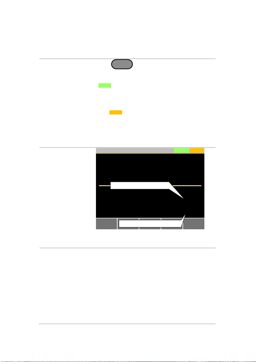
Description
A Fast Sequence is run the same way as a
normal load.
Operation
1. Press
FUNC
> Fast Sequence[F3].
2. Turn fast sequence mode on by setting
F. Seq.[F1] to On.
FSEQ
will appear at the top of the
display when F. Seq. is On.
3. Turn the load on.
The fast sequence/chain starts immediately.
The
FSEQ
icon turns orange when the load is
turned on.
4. When a fast sequence is running, the screen
displays which step and loop is currently active.
“Sequence Complete” will be shown on the
display at the end of the sequence.
Display:
Fast Sequence
Running
FSEQRS232
31/Oct/2013
Run F.Seq.
0.998
V
153.10
mA
0.1528
w
Step
Loop: 0001
0023
Current loop number
Current step number
Background
The OCP test function creates an automatic test
to test the OCP of power supply products.
This test will test to see when the over current
protection of a power supply is tripped and return
the measurements for the voltage and current
when the over current protection was tripped. The
LSG also has a user-defined cutoff setting in the
event that the power supply OCP fails.
The diagram below shows an example of the
OCP Test Automation function:
3-3-8. Running a Fast Sequence
3-4. OCP TestAutomation
87

Example
The test current increases from a starting value
(Start C) to an end value (End C). The current
increases in steps (set by Step_C) with a set step
time (set by Step_T) until the power supply’s OCP
is tripped or the End C current level is reached.
Parameters
OCP. No
Selects one of 12 OCP test setup
memories.
Range
High(CC Mode High), Mid(CC Mode
Middle) and Low(CC Mode Low)
Start Current
(Start C)
Starting current value for the test.
End Current
(End C)
The current value that will end the
test. The value must be higher than
the OCP value of the DUT you are
testing. This parameter is used as a
fail-safe for if the over current
protection of the DUT fails. If the
measured current is reaches End
Current value it would then indicate
that the power supply OCP failed.
Step Current
(Step_C)
Sets the step resolution of the current.
Last Current
(Last_C)
Sets the final current value after OCP
has been tripped. This is the steadystate current draw after the OCP has
been tripped.
88
 Loading...