

INSTRUCTION MANUAL
REGULATED DC POWER SUPPLY
PDS-A SERIES
PDS20-10A PDS20-18A PDS20-36A
PDS36-6A PDS36-10A PDS36-20A
PDS60-6A PDS60-12A
OPTIONAL INTERFACE UNITS
FOR PDS-A SERIES
IF-71RS IF-70GU IF-71LU
B71-0194-01

■ About Brands and Trademarks
The company and product names described in this manual are the brands and trademarks owned by the respective
companies or organizations in each country and region
■ About the Instruction Manual
Permission from the copyright holder is needed to reprint the contents of this manual, in whole or in part. Be aware that
the product specifications and the contents of this manual are subject to change for the purpose of improvement.

CONTENTS
USING THE PRODUCT SAFETY ............................................................................................................... Ⅰ-Ⅲ
1. PDS-A SERIES ________________________________________________________ 1
1-1. About This Manual .......................................................................................................................... 1
1-2. Outline of Product ............................................................................................................................ 1
1-3. Features........................................................................................................................................... 1
1-3-1. PDS-A Power Supply Unit ........................................................................................................ 1
1-3-2. IF-71RS (option) ....................................................................................................................... 2
1-3-3. IF-70GU (option) ....................................................................................................................... 2
1-3-4. IF-71LU (option) ....................................................................................................................... 2
1-3-5. Cable for master-slave operation (option) ................................................................................ 2
1-3-6. Handle (option) ......................................................................................................................... 2
2. PRIOR TO USE _______________________________________________________ 3
2-1. Accessories ..................................................................................................................................... 3
2-2. Connecting the power cable ............................................................................................................ 4
2-3. Connecting to the output terminals ................................................................................................. 4
2-3-1. Attaching the output grounding cable ....................................................................................... 4
2-3-2. Connecting the voltage remote sensing cables ....................................................................... 5
2-3-3. Attaching the rear output terminal cover .................................................................................. 5
2-4. Caution on Connecting to a Capacitive Load .................................................................................. 5
2-5. Connecting the protective grounding terminal on the bottom face ................................................. 6
2-6. Caution on mounting the unit in a rack ........................................................................................... 6
2-7. Connecting the Power Cable to the Primary Power ....................................................................... 6
2-8. Installation Environments ................................................................................................................ 7
3. PANELS _____________________________________________________________ 8
3-1. Front Panel ...................................................................................................................................... 8
3-2. Operation Panel............................................................................................................................... 9
3-3. Rear Panel ..................................................................................................................................... 12
4. GENERAL INSTRUCTIONS_____________________________________________ 15
4-1. Connecting loads ........................................................................................................................... 15
4-2. Alarm .............................................................................................................................................. 16
5. FUNCTIONS AND OPERATION PROCEDURES ____________________________ 17
5-1. Operation modes ........................................................................................................................... 17
5-2. Turning On Power.......................................................................................................................... 17
5-2-1. Display when power is turned on ........................................................................................... 17
5-2-2. Performing a unit scan while using a parallel connection ...................................................... 17
5-2-3. Recalling Settings When Turning on Power, and Saving the Setting Data ........................... 18
5-3. Basic Operation ............................................................................................................................. 19
5-3-1. Voltage setting procedure ....................................................................................................... 19
5-3-2. Current setting procedure ....................................................................................................... 19
5-3-3. Fine adjustment of voltage/current ......................................................................................... 19
5-4. Output Functions ........................................................................................................................... 20
5-5. Memory Function ........................................................................................................................... 20
5-5-1. Storing and recalling preset voltage/current data ....................................................................... 20
5-6. Switching the display in the Voltage/Current Indicator Display. ......................................................... 21
5-6-1. Switching between the set voltage/current display and output voltage/current display......... 21

5-6-2. Displaying Power in the Voltage and Current Indicators ........................................................ 22
5-7. Protective Functions ...................................................................................................................... 24
5-7-1. Display when protective functions are activated .................................................................... 24
5-7-2. Modification of the Set Values of Protective Functions .......................................................... 24
5-7-3. Deactivating Protective Functions ............................................................................................. 25
5-8. Key Lock / Local Function ............................................................................................................. 25
5-8-1. Key lock and unlock procedures ............................................................................................... 25
5-8-2. Remote mode deactivation procedure ................................................................................... 26
6. SETTING WITH THE MENU KEY ________________________________________ 27
6-1. Output Off Timer ............................................................................................................................ 28
6-1-1. Setting the output off timer ...................................................................................................... 28
6-1-2. Operating the output off timer ................................................................................................... 29
6-2. Specifying the automatic cancellation time of the setting menu display ............................................ 30
6-3. Specifying Settings when the Power Is Turned On ....................................................................... 31
6-3-1. Recalling preset values when the power is turned on................................................................ 31
6-3-2. Setting the output when the power is turned on ........................................................................ 32
6-3-3. Setting the CC priority mode ..................................................................................................... 33
6-3-4. Setting the display while the output is off .................................................................................. 36
6-3-5. Default setting of the power relay when the power is turned on ............................................ 37
6-3-6. Specifying the baud rate while in IF-71RS PDS mode .............................................................. 38
6-4. Clearing the Memory ..................................................................................................................... 39
6-4-1. Clearing all the setting data stored in the unit ........................................................................ 39
6-4-2. Clearing the setting data for manual operation ...................................................................... 40
6-4-3. Clear the setting data of sequence operation ........................................................................ 41
6-4-4. Clearing the setting data for IF-71LU IP address setting ....................................................... 42
7. MASTER-SLAVE OPERATION __________________________________________ 44
7-1. Configuration of Master and Slave Units ...................................................................................... 44
7-1-1. Configuring the master and slave units .................................................................................. 44
7-1-2. Specifying the number of units ............................................................................................... 46
7-2. Parallel Master-Slave Operation ................................................................................................... 48
7-3. Serial Master-Slave Operation ...................................................................................................... 49
8. SEQUENCE OPERATION ______________________________________________ 50
8-1. Setting of Sequence Operation ..................................................................................................... 50
8-1-1.Turning on the power switch with sequence operation ........................................................... 50
8-1-2. Setting the unit to start in sequence operation by turning the power switch on .................. 50
8-2. Sequence Programs ...................................................................................................................... 52
8-2-1. Step No. and setting items ..................................................................................................... 52
8-2-2. Setting step execution ............................................................................................................ 52
8-3. Confirming the Step No. and the Step Being Executed ................................................................ 53
8-3-1. Confirming the step No. while the sequence program is stopped ......................................... 53
8-3-2. Confirming the step No. being executed during sequence program execution ..................... 53
8-4. Confirming the Setting Items for Steps.......................................................................................... 54
8-5. Confirming the settings for sequence program execution ............................................................ 55
8-6. Executing Sequence Programs ..................................................................................................... 56
8-6-1. Automatic execution of sequence programs .......................................................................... 56
8-6-2. Paused and resumed sequence programs ............................................................................ 57

8-6-3. Manual execution of sequence programs .............................................................................. 58
8-6-4. Stopping sequence programs ................................................................................................. 59
9. OPERATION BY EXTERNAL ANALOG SIGNAL ____________________________ 60
9-1. Analog Interface Boards ................................................................................................................ 60
9-1-1. Cautions on applying analog IF boards .................................................................................. 60
9-1-2. Wiring an analog signal to the standard board....................................................................... 61
9-2. Operating the Analog IF Board ...................................................................................................... 63
9-2-1. Setting the Voltage ................................................................................................................. 63
9-2-2. Adjusting the set voltage......................................................................................................... 65
9-2-3. Current setting ........................................................................................................................ 66
9-2-4. Adjusting the set current ......................................................................................................... 68
9-2-5. Turning the output on/off through external contacts ............................................................... 69
9-2-6. Checking the status when the output is off ............................................................................ 71
9-2-7. Main relay ON/OFF operation ................................................................................................ 71
10. INTERFACE OPTION _________________________________________________ 72
10-1. Accessories ................................................................................................................................. 72
11. USING DIGITAL COMMUNICATION INTERFACE FOR REMOTE CONTROL _____ 73
11-1. Outline .......................................................................................................................................... 73
11-1-1. IF-70GU ................................................................................................................................. 73
11-1-2. IF-71LU .................................................................................................................................. 74
11-1-3. IF-71RS ................................................................................................................................. 75
11-1-4. Cable and connector settings .................................................................................................. 76
11-1-5. Address settings ..................................................................................................................... 77
11-1-6. Checking the mode and address settings of the interface card ................................................ 79
11-1-7. GP-IB connection ................................................................................................................... 80
11-1-8. USB connection ...................................................................................................................... 80
11-1-9. RS-232C connection .............................................................................................................. 81
11-1-10. LAN connection .................................................................................................................... 81
11-1-11. Local bus connection ............................................................................................................ 82
11-2. Communication Control Commands ........................................................................................... 83
11-2-1. Communication commands table ............................................................................................ 83
11-2-2. Automatic message output...................................................................................................... 84
11-2-3. Command format .................................................................................................................... 84
11-3. Commands .................................................................................................................................. 86
11-3-1. Voltage setting (VOLT) ........................................................................................................... 86
11-3-2. Current setting (AMP) ............................................................................................................. 86
11-3-3. OVP setting (OVP) ................................................................................................................. 86
11-3-4. UVP setting (UVP) .................................................................................................................. 86
11-3-5. OCP setting (OCP) ................................................................................................................. 86
11-3-6. Output setting (OUTPUT) ....................................................................................................... 87
11-3-7. Status query (XSTATUS) ........................................................................................................ 87
11-3-8. Recalling preset settings (PRESET) ....................................................................................... 87
11-3-9. Saving preset settings (SETPRE) ........................................................................................... 87
11-3-10. Preset voltage setting (PREVOLT) ........................................................................................ 88
11-3-11. Preset current setting (PREAMP) .......................................................................................... 88
11-3-12. Power monitor display setting(MONDSP) ............................................................................. 88

11-3-13. Power-off display setting(DSPY) ........................................................................................... 88
11-3-14. Monitor display switching (CHECK) ...................................................................................... 89
11-3-15. CC priority mode setting when the output is turned on (CCPRIO) ......................................... 89
11-3-16. Output off timer setting (OFFTM) .......................................................................................... 89
11-3-17. Automatic cancellation time setting for the setting menu display (ESC) ................................. 89
11-3-18. Main relay setting (POWER) ................................................................................................. 90
11-3-19. Unlocking (GTL) ................................................................................................................... 90
11-3-20. Local lock out setting (LLO) ................................................................................................. 90
11-3-21. Sequence operation setting when the power is turned on (PONSEQ) ................................... 90
11-3-22. Preset setting when the power is turned on (PONPRE) ........................................................ 90
11-3-23 Output setting when the power is turned on (PONOUT) ......................................................... 91
11-3-24. Main relay setting when the power is turned on (PONPOW) ................................................. 91
11-3-25. Notification setting 1 (MASK) ................................................................................................ 91
11-3-26. Notification setting 2 (AMASK) .............................................................................................. 92
11-3-27. Notification setting 3 (SMASK) .............................................................................................. 92
11-3-28. Querying alarm status (ALM) ................................................................................................ 92
11-3-29. Alarm reset (EXIT_ALM) ....................................................................................................... 92
11-3-30. Clearing sequence programs (SCLR) ................................................................................... 92
11-3-31. Writing sequence program (XSWRITE) ................................................................................ 93
11-3-32. Reading out a sequence program (XSREAD) ....................................................................... 94
11-3-33. Sequence start point setting (SSADR) .................................................................................. 94
11-3-34. Sequence end point setting (SEADR) ................................................................................... 94
11-3-35. Sequence execution mode setting (SMODE) ........................................................................ 95
11-3-36. Sequence repeat cycle setting (SCYCLE) ............................................................................. 95
11-3-37 Sequence mode setting (CHGSEQ) ...................................................................................... 95
11-3-38. Panel operation mode setting (CHGNORM) ......................................................................... 95
11-3-39. Sequence start (SSTART) .................................................................................................... 95
11-3-40. Sequence stop (SSTOP) ...................................................................................................... 95
11-3-41. Sequence pause (SPAUSE) ................................................................................................. 96
11-3-42. Sequence jump (SSTEP) ...................................................................................................... 96
11-3-43. Reading out the sequence execution status (SRUN) ......................................................... 96
11-3-44. Reset (*RST) ........................................................................................................................ 96
11-3-45. Function reset (RESET) ........................................................................................................ 96
11-3-46. Reading out the status byte (*STB) ....................................................................................... 97
11-3-47. Reading out the product information (*IDN) ........................................................................... 97
11-3-48. Querying the model and specifications (MODEL) .................................................................. 97
11-3-49. Local bus setting (ADRS) ...................................................................................................... 98
11-3-50. Returning the product name of the unit (UNIT?) .................................................................... 98
11-3-51. Query-dedicated PC address for device identification (LPCAD?) .......................................... 98
11-4. Cautions about communication ................................................................................................... 99
11-5. Compatibility of PDS-A series and PDS series. .......................................................................... 99
11-6. Communication Specifications .................................................................................................. 100
Appendix A. TROUBLE SHOOTING _______________________________________ 104
Appendix B. OUTSIDE DIMENSIONS _____________________________________ 105
Appendix C. SPECIFICATIONS __________________________________________ 106
I
USING THE PRODUCT SAFELY
■ Preface
To use the product safely, read instruction manual to the end.
Before using this product, understand how to correctly use it.
If you read the manuals but you do not understand how to use it, ask us or your local dealer.
After you read the manuals, save it so that you can read it anytime as required.
■ Pictorial indication
The manuals and product show the warning and caution items required to safely use the product.
The following pictorial indication and warning character indication are provided.
<Pictorial indication>
Some part of this product or the manuals may show this pictorial indication.
In this case, if the product is incorrectly used in that part, a serious danger may be brought
about on the user's body or the product.
To use the part with this pictorial indication, be sure to refer to the manuals.
WARNING
!
If you use the product, ignoring this indication, you may get killed or seriously injured.
This indication shows that the warning item to avoid the danger is provided.
CAUTION
!
If you incorrectly use the product, ignoring this indication, you may get slightly injured or
the product may be damaged.
This indication shows that the caution item to avoid the danger is provided.
Please be informed that we are not responsible for any damages to the user or to the third person, arising from
malfunctions or other failures due to wrong use of the product or incorrect operation, except such responsibility for
damages as required by law.

II
USING THE PRODUCT SAFELY
WARNING
!
CAUTION
!
■ Do not remove the product's covers and panels
Never remove the product's covers and panels for any purpose.
Otherwise, the user's electric shock or fire may be incurred.
■ Warning on using the product
Warning items given below are to avoid danger to user's body and life and avoid the damage or deterioration of the
product. Use the product, observing the following warning and caution items.
■ Warning items on power supply
● Power supply voltage
The rated power supply voltages of the product are 100, 230 and 240VAC. The rated power supply voltage for
each product should be confirmed by reading the label attached on the back of the product or by the “rated” column
shown in the instruction manual. The specification of power cord attached to the products is rated to 125VAC
for all products which are designed to be used in the areas where commercial power supply voltage is not higher
than 125VAC. Accordingly, you must change the power cord if you want to use the product at the power supply
voltage higher than 125VAC. If you use the product without changing power cord to 250VAC rated one, electric
shock or fire may be caused. When you used the product equipped with power supply voltage switching
system, please refer to the corresponding chapter in the instruction manuals of each product.
● Power cord
(IMPORTANT) The attached power cord set can be used for this device only.
If the attached power cord is damaged, stop using the product and call us or your local dealer.
If the power cord is used without the damage being removed, an electric shock or fire may be caused.
● Protective fuse
If an input protective fuse is blown, the product does not operate. For a product with external fuse holder, the fuse
may be replaced. As for how to replace the fuse, refer to the corresponding chapter in the instruction manual.
If no fuse replacement procedures are indicated, the user is not permitted to replace it. In such case, keep the
case closed and consult us or your local dealer. If the fuse is incorrectly replaced, a fire may occur.
■ Warning item on Grounding
If the product has the GND terminal on the front or rear panel surface, be sure to ground the product to safely use it.
■ Warnings on Installation environment
● Operating temperature and humidity
Use the product within the operating temperature indicated in the “rating” temperature column.
If the product is used with the vents of the product blocked or in high ambient temperatures, a fire may occur.
Use the product within the operating humidity indicated in the “rating” humidity column.
Watch out for condensation by a sharp humidity change such as transfer to a room with a different humidity.
Also, do not operate the product with wet hands. Otherwise, an electric shock or fire may occur.
● Use in gas
Use in and around a place where an inflammable or explosive gas or steam is generated or stored may result in an
explosion and fire. Do not operate the product in such an environment.
Also, use in and around a place where a corrosive gas is generated or spreading causes a serious damage to the
product. Do not operate the product in such an environment.
● Installation place
Do not insert metal and inflammable materials into the product from its vent and spill water on it.
Otherwise, electric shock or fire may occur.

III
USING THE PRODUCT SAFELY
■ Do not let foreign matter in
Do not insert metal and inflammable materials into the product from its vent and spill water on it.
Otherwise, electric shock or fire may occur.
■ Warning item on abnormality while in use
If smoke or fire is generated from the product while in use, stop using the product, turn off the switch, and remove the
power cord plug from the outlet. After confirming that no other devices catch fire, ask us or your local dealer.
■ Input / Output terminals
Maximum input to terminal is specified to prevent the product from being damaged.
Do not supply input, exceeding the specifications that are indicated in the "Rating" column in the instruction manual of
the product. Also, do not supply power to the output terminals from the outside.
Otherwise, a product failure is caused.
■ Calibration
Although the performance and specifications of the product are checked under strict quality control during shipment
from the factory, they may be deviated more or less by deterioration of parts due to their aging or others.
It is recommended to periodically calibrate the product so that it is used with its performance and specifications stable.
For consultation about the product calibration, ask us or your local dealer.
■ Daily Maintenance
When you clean off the dirt of the product covers, panels, and knobs, avoid solvents such as thinner and benzene.
Otherwise, the paint may peel off or resin surface may be affected. To wipe off the covers, panels, and knobs, use a
soft cloth with neutral detergent in it.
During cleaning, be careful that water, detergents, or other foreign matters do not get into the product.
If a liquid or metal gets into the product, an electric shock and fire are caused.
During cleaning, remove the power cord plug from the outlet.
Use the product correctly and safely, observing the above warning and caution items.
Because the instruction manual indicates caution items even in individual items, observe those caution items to correctly
use the product.
If you have questions or comments about the manuals, ask us or E-Mail us.

1
1
1. PDS-A SERIES
1-1. About This Manual
This manual applies to the following PDS-A series power supply units and optional interface units.
● PDS-A series:
Rated
Voltage
Rated Current
200W
216W
360W
720W
20V
PDS20-10A
-
PDS20-18A
PDS20-36A
36V
-
PDS36-6A
PDS36-10A
PDS36-20A
60V - -
PDS60-6A
PDS60-12A
● Optional interface units for the PDS-A series
IF-71RS,IF-70GU,IF-71LU
1-2. Outline of Product
This product is a small, light-weight, and low-noise DC power supply unit equipped with a switching system and
dropper system. It is incredibly reliable and comes with a variety of protective functions, making it ideal for use as a
power source in industrial applications, such as the reliability tests, durability tests, and aging of electronic parts.
This power supply unit has a 3-point preset function as well as protective functions for overvoltage, undervoltage,
and overcurrent. It is also equipped with an output off timer, sequence function, CC priority mode for when the output
is on, and an external analog signal operation function. This wide range of functions enables this power supply unit to
be used for a variety of application. In addition, the unit is designed to minimize the harmonic current of the power
supply, which exerts a harmful influence on the AC line.
The standard analog control board is to be replaced with an optional interface board equipped with communication
functions. There are three available models of optional boards (the IF-71RS, IF-70GU, and IF-71LU).
1-3. Features
1-3-1. PDS-A Power Supply Unit
・Low ripple and low noise
A series transistor is used for output voltage control to minimize the output ripple and noise.
・ Selection of setting digits for voltage and current setting
The output voltage and current are indicated by 4 digits. You can select a digit to set the voltage and the current.
The PDS-A power supply unit is also equipped with a fine adjustment function for instances in which more precise
setting capabilities are required.
・ Preset function
The unit has a preset memory for 3 setting points in which different voltage and current settings can be stored. This
function enables you to easily change the voltage and current settings.
・ Output off timer function
To prevent battery overcharge etc., this function automatically turns the output off after a preset amount of time has
passed while the output is on.
・ CC priority mode
Compared to general switching power supply units, the PDS-A power supply unit is better able to reduce current
overshoot, thanks to our original current-overshoot inhibit circuit. This circuit produces a load that enables the unit
to operate at a constant current while the output is on.
・ Sequence function
Sequence programs can be written in the unit from a computer via the optional interface board (IF-70RS, IF-70GU,
and IF-71LU).
Sequence programs can be executed by performing panel or computer operations.
You can also perform sequence operations with a maximum of 1000 steps by using a program written by the
computer. The minimum step unit is 50ms.
・ Remote sensing function
This function uses the remote sensing terminal to compensate for voltage drop caused by the wires.
・ Protective functions
The unit is equipped with functions designed to protect the power supply, such as overvoltage, undervoltage, and

2
2
overcurrent on the primary side, as well as overvoltage, overcurrent, internal overheat, and front output overvoltage
on the secondary side.
The unit is also equipped with OVP (over-voltage protection), UVP (under-voltage protection), and OCP
(over-current protection) for the load. The setting values for these protective functions are changeable.
・ Master-slave operation
The PDS-A power supply unit can perform master-slave operation by connecting three units of the same model in a
parallel connection, and up to two units in the serial connection.
・ External analog signal operation
When setting the voltage and current by external voltage and resistance, the setting values set externally will be
superimposed on the setting values set on the panel.
The external setting values can be adjusted on the panel.
The output can be turned on and off by entering external terminal.
・ Dispersion circuit for rush current prevention
The PDS-A power supply unit is able to restrain and minimize the primary side current and voltage distortions
caused by rush current on the primary side at the time the unit is switched on, thanks to the main relay’s on/off
operation and our original dispersion circuit for rush current prevention.
・ Power factor correction circuit, as well as voltage and current range for worldwide use
The PDS-A power supply unit is equipped with a power factor correction circuit that has a rated output of
approximately 0.99.
It is operable with supply voltages ranging from 100VAC to 240VAC, without changing the settings.
・ Forced air cooling via front air intake
The front of the PDS-A power supply unit is equipped with a cooling fan motor. This helps to lower the ambient
temperature around the fan motor and improve its reliability.
・ CE marking
The PDS-A power supply unit can perform CE marking (under voltage directive, EMC directive). It also complies with
the regulations for the harmonic current of power supply units.
1-3-2. IF-71RS (option)
・ Units equipped with the IF-71RS can be connected to a computer and controlled by RS-232C.
As an expansion, the IF-71RS can also control 31 PDS-A power supply units via a local bus connection.
・ When you set IF-71RS in PDS communication mode, you can let PDS-A power supply work by PDS power supply
communication command.
1-3-3. IF-70GU (option)
・ The IF-70GU is connected to a computer through a GP-IB or USB.
Fourteen units may be connected with a computer through GP-IB, or 32 units may be connected through USB.
• Units connected to the computer can be connected with 31 PDS-A power supply units via a local bus connection.
1-3-4. IF-71LU (option)
・ A LAN or USB can be used to connect to a computer.
A total of 32 units can be connected to the computer via a USB.
・ A total of 31 PDS-A power supply units can be connected via a local bus to the unit that is connected to the
computer.
1-3-5. Cable for master-slave operation (option)
• Cable for parallel master-slave
OP-23P3 : Connectable with three PDS-A power supply units.
・ Cable for in-series master-slave
OP-23S : Connectable with two PDS-A power supply units.
CAUTION
!
When connecting cables, make sure to connect the correct cables.
Connecting the wrong cables may cause product failure.
1-3-6. Handle (option)
・ HK-11 : Attachable with this models

3
3
2. PRIOR TO USE
2-1. Accessories
Make sure the accessories are attached correctly. If there are any problems, please contact one of our sales branches.
Accessories vary by model.
<PDS-A series power supply unit accessories>
Power cable: 1 pc
For 125V: [E30-5632]
For 250V: [E30-5643]
CD-ROM(Manual) 1 pc
Rear output terminal cover: [F07-1586] 1 pc
See “2-3-3. Attaching the rear output terminal cover”.
Output ground cable: [E38-3353] 1 pc
See “2-3-1. Attaching the output grounding cable”.
Contents:
Hexagon head bolt (P-3): 2 pcs
Flat washer : 2 pcs
Hexagon nut : 2 pcs
Bolts set: [N99-0416] 1 set
For connecting load line to rear output terminal.
See “2-3. Connecting to the output terminals”.
M3 Small screw washer : [N67-3006-41] 1 set
Used to fix the ground cable to the rear output terminal.
See “2-3-1. Attaching the output grounding cable”.
M3 Large screw washer : [N66-3008-41] 2 sets
Used to attach the rear output terminal cover.
See “2-3-3. Attaching the rear output terminal cover”.
M4 Small screw washer : [N67-4008-41] 1 set
Used to connect the bottom protective grounding terminal.
See “2-5. Connecting the protective grounding terminal
on the bottom face”.
* The cushion for the ferrite core is not included with the 1200W power cable: [E30-5637].
4
4
2-2. Connecting the power cable
The power cable should be connected to an AC inlet or an input terminal block. Make sure to use a power cable that
matches the input voltage of the unit. Because the voltage rating of the supplied power cable is 125VAC, you must use a
different cable when a power voltage greater than 125VAC is used.
Perform this operation before connecting the power cable to an AC outlet or the distribution panel.
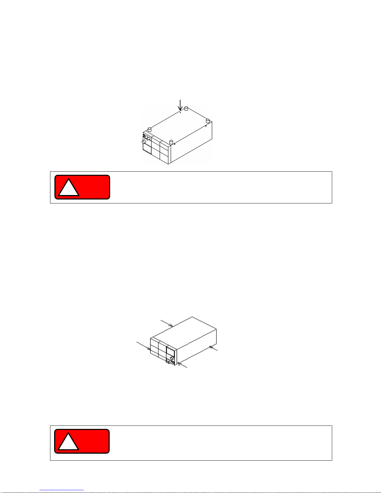
2-3. Connecting to the output terminals
Use the supplied bolt set to connect the load cable to the rear output terminals.
Adjust the tightening torque of each bolt to 25 kgf/cm.
Check the connection between the load and the output terminals of the unit. Make sure that the polarity is not
inverted, and that no short circuits have occurred.
Fig. 2-2 Connecting the load cable to the rear output terminals
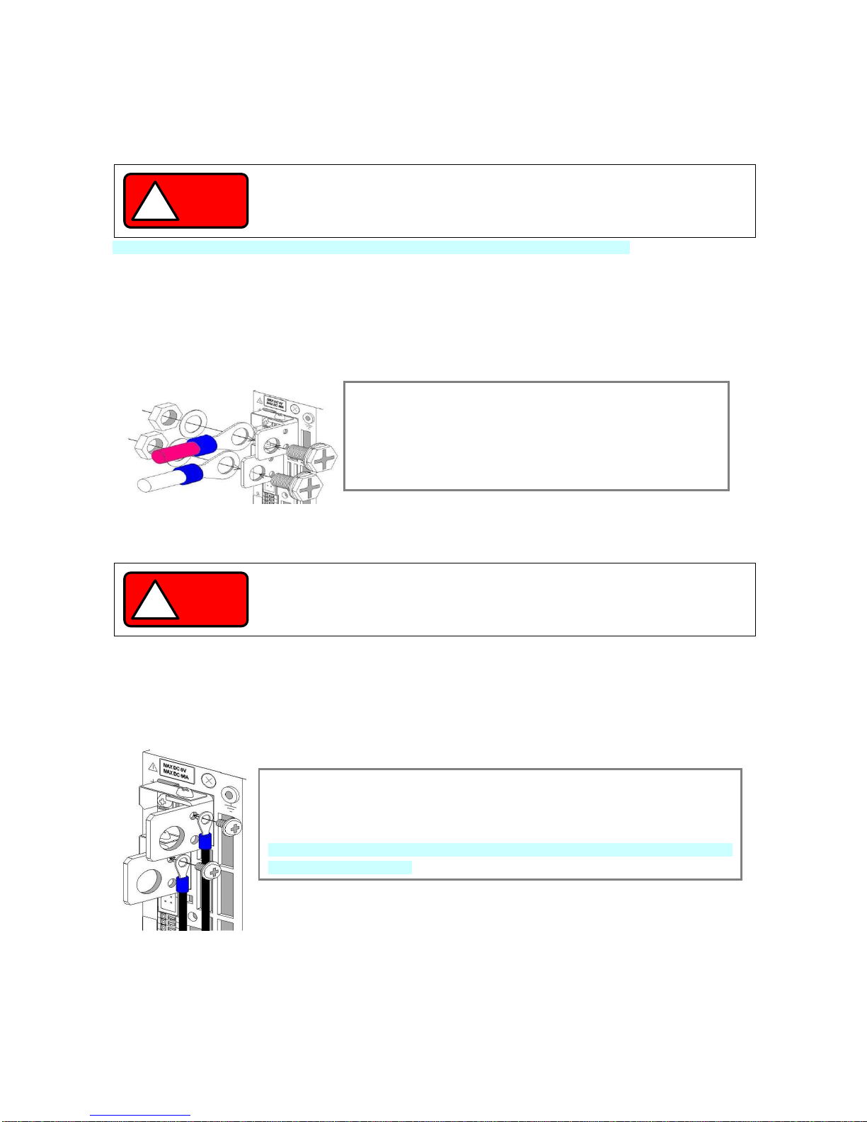
2-3-1. Attaching the output grounding cable
(You do not need to perform this operation if the output is not to be grounded.)
Use the M3 Small screw and washer to attach the grounding cable to one of the rear output terminals.
Tightening torque of screw: 5kgf/cm.
WARNING
!
Make sure to properly connect the power cable. Failure to do so may result in
electric shock or fire.
Using the unit without the AC input terminal cover may result in electric shock or
fire.
WARNING
!
Make sure the voltage of the unit’s output terminals has sufficiently fallen before
touching and operating the load or output terminals. Failure to do so may result in
electric shock.
From the left side of the rear output terminals, attach the grounding cable to the M3 hole
of one of the output terminals.
Attach the grounding cable to either the positive output terminal or the negative output
terminal. Do not attach the cable to both.
If you attach the grounding cable to both the positive and negative output terminals, the
unit output will short circuit.
Attach a round crimp-style terminal (inner diameter of at least 6.4 mm) to the
load cable.
Insert the bolt into the hole from left side of the output terminal.
From the right side of the output terminal, first attach the load cable (with the
round crimp-style terminal attached), followed by the washer and then the nut.
Finally, secure the bolt.
5
5
2-3-2. Connecting the voltage remote sensing cables
You only need to perform this operation if you plan to use the voltage remote sensing function of the unit.
Use the removed M3 screws to attach the voltage remote sensing cables to the voltage remote sensing terminals.
Tightening torque of screw: 5kgf/cm
Carefully store the positive and negative shorting bars and the two M3 screws that were removed.
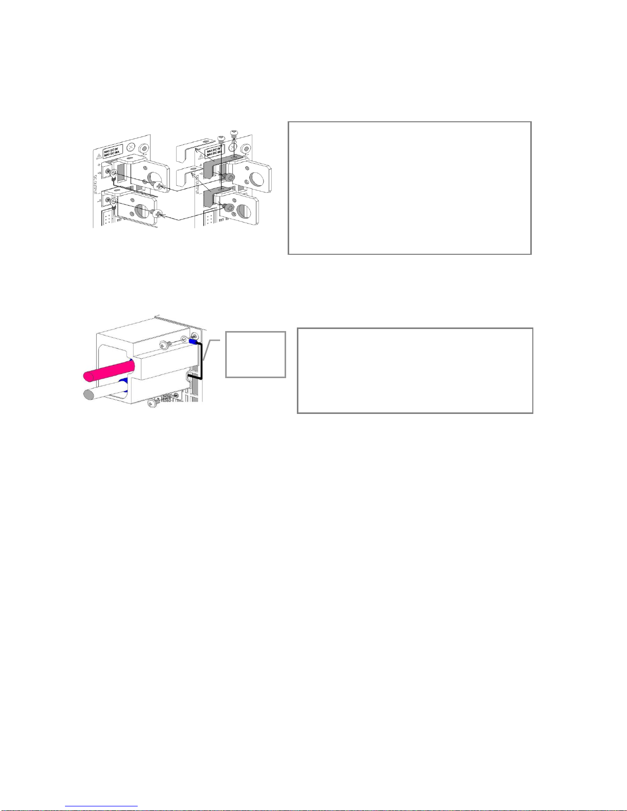
2-3-3. Attaching the rear output terminal cover
The rear output terminal cover should always be attached even when rear output terminals of the unit are not in use.
Use the M3 Large screw with washer to attach the rear output terminal cover.
Tightening torque of screw: 5kgf/cm.
2-4. Caution on Connecting to a Capacitive Load
To maintain an output voltage of approximately 0 V when the output is off, the unit is equipped with a discharge circuit
for removing the electric charge from the output capacitor.
When the output is off, it takes approximately 1 second for the discharge circuit to remove the electric charge from the
output capacitor when the capacitor is fully charged to its rated voltage.
If a capacitive load, such as a battery or capacitor, is connected to the unit and used, it takes longer to lower the output
voltage when the output is off. If the output is turned off while a capacitive load is connected, be sure to use a
voltmeter to confirm that the voltage has sufficiently fallen before touching the output terminal or the load
The discharge circuit for the output capacitor does not work if the unit’s output HI -R function is used.
Compared to when the output HI-R function is not used, it takes longer for voltage to fall when a capacitive load is
used.
Run the load cable and the voltage remote sensing cable
through the output terminal cover, and then fix the output
terminal cover to the unit, using the two large screws with
washers.
Fix the output grounding cable to the output grounding
terminal, together with the output terminal cover.
Remove the M3 screws (4 screws) from the positive and
negative rear output terminals and the positive and negative
voltage remote sensing terminals, and then remove the
positive and negative shorting bars.
Attach the positive and negative voltage remote sensing
cables to the positive and negative voltage remote sensing
terminals.
Attach a round crimp-style terminal (inner diameter of at
least 3.2mm, with the smallest possible outer diameter) to
the voltage remote sensing cables.
Output
grounding
cable
6
6
2-5. Connecting the protective grounding terminal on the bottom face
There is a protective grounding terminal on the bottom face of this unit.
To ensure the safe use of this product, follow the procedure below to connect the protective grounding terminal.
1. Attach the wire (recommended by the manufacturer) for round crimp-style terminals V1.25-M4 (JST) or equivalent.
2. Attach the round crimp-style terminal to the cable.
3. Attach the cable with round crimp-style terminal to the protective grounding terminal on the bottom face of the unit,
using the accessory M4 screw for the grounding connection to secure the cable.
2-6. Caution on mounting the unit in a rack
When mounting the unit in a rack, use one of the following attachments:
・ Rack mount adapter RM-608J (for JIS rack)
• RM-608E (for EIA rack) and rack mount frame attachment RJ-608-1/2 (for 1/2 rack width)
• RJ-608-1/3 (for 1/3 rack width)
When mounting the unit in a rack, replace the screws on the left and right sides of the unit (two on each side) with the
flat countersunk head screws (N32-3006-41) that are included with RJ-608-1/2 or RJ-608-1/3.
When mounting the unit in a rack, remove the screw for the protective grounding terminal on the bottom face of the unit.
For your own safety, make sure to securely connect the rack to the ground before using the unit.
2-7. Connecting the Power Cable to the Primary Power
Be sure to turn off the power switch before connecting the power cable to the AC outlet or distribution panel.
Because the voltage rating of the supplied power cable is 125VAC, you must use a different cable when a power
voltage greater than 125VAC is used.
Make sure to plug the supplied power cable into a D-class grounded AC outlet.
WARNING
!
Make sure to properly connect the protective grounding terminal on the bottom face.
Failure to do so may result in electric shock.
If you do not connect the protective grounding terminal on the bottom face, it will
come off from the CE conformity.
WARNING
!
Plugging the power cable into an outlet or distribution panel that is not properly
grounded may result in electric shock or fire. Be sure to ask a qualified engineer to
connect the power cable to the distribution panel.

7
7
2-8. Installation Environments
・ If the unit is used in a hot place and the internal temperature of the unit rises, the built-in overheat protection circuit
activates and turns off the output. Do not use the unit in a location where the grill in the front panel or air outlet port
in the rear panel is blocked. Blocking these ports will cause the internal temperature to rise. Maintain sufficient
distance between these ports and objects. In some conditions, hot air may blow out of the air outlet port in the rear
panel. Be careful.
・ Do not use the PDS-A power supply unit in a place with a lot of dust or corrosive gas. These substances can cause
the product to deteriorate.
・ Do not use the unit on an incline or a place subject to vibration. Doing so can cause the unit to fall off the rack or fall
over, which may result in damage to the unit or personal injury.
8
8
3. PANELS
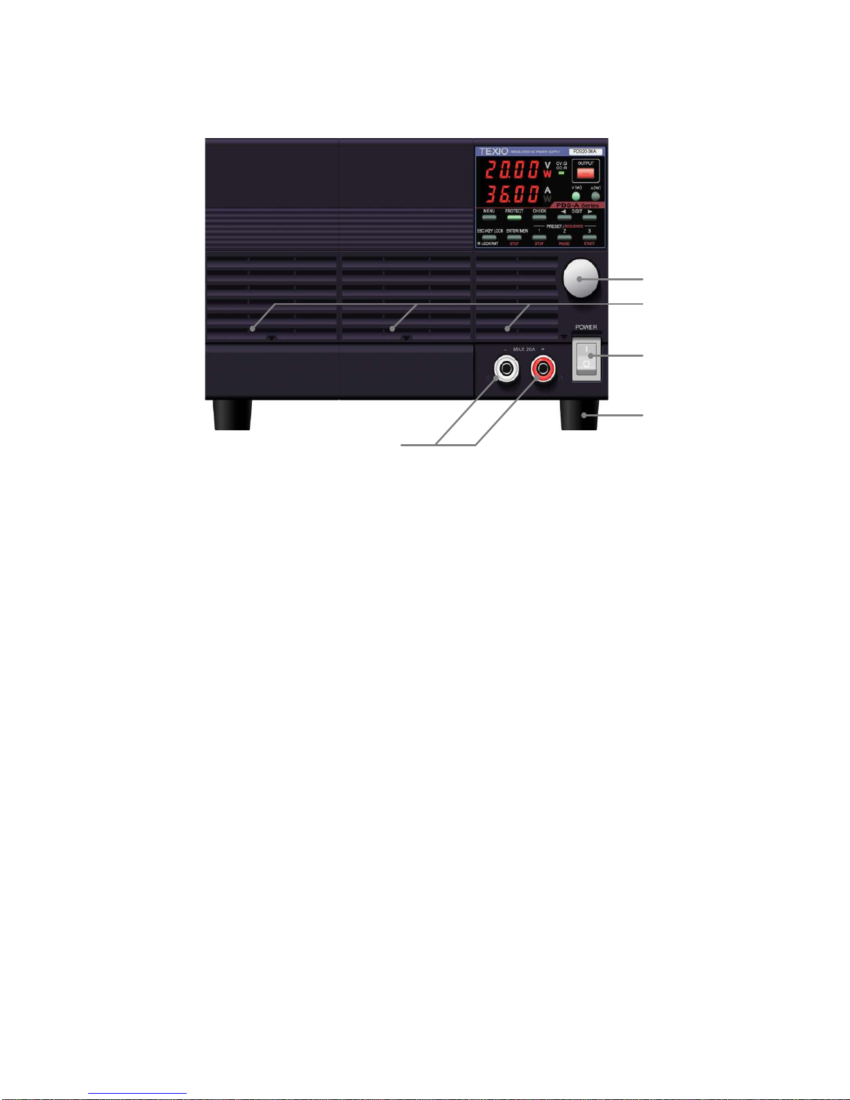
3-1. Front Panel
2
5
1
4
3
Fig. 3-1 Front Panel (The above figure shows the front panel of the PDS20-36A.)
1. Power switch
・ Turns the AC power on (I)and off(O).
・ Do not do the setting that comes to have difficulty in ON/OFF of the power switch.
2. Front output terminals
• Front output terminals with a current limit of 20A. Use the unit within the current limit
3. Rotary encoder
• Changes the set voltage and current, and is used to set functions.
4. Grill
• Air intake port.
Push up the mark in the bottom center of the grill to detach the cover when cleaning or replacing the dust filter
inside.
5. Rubber shoes
• Detachable.
If the unit is mounted in a rack and the shoes are not needed, they may be removed.
9
9
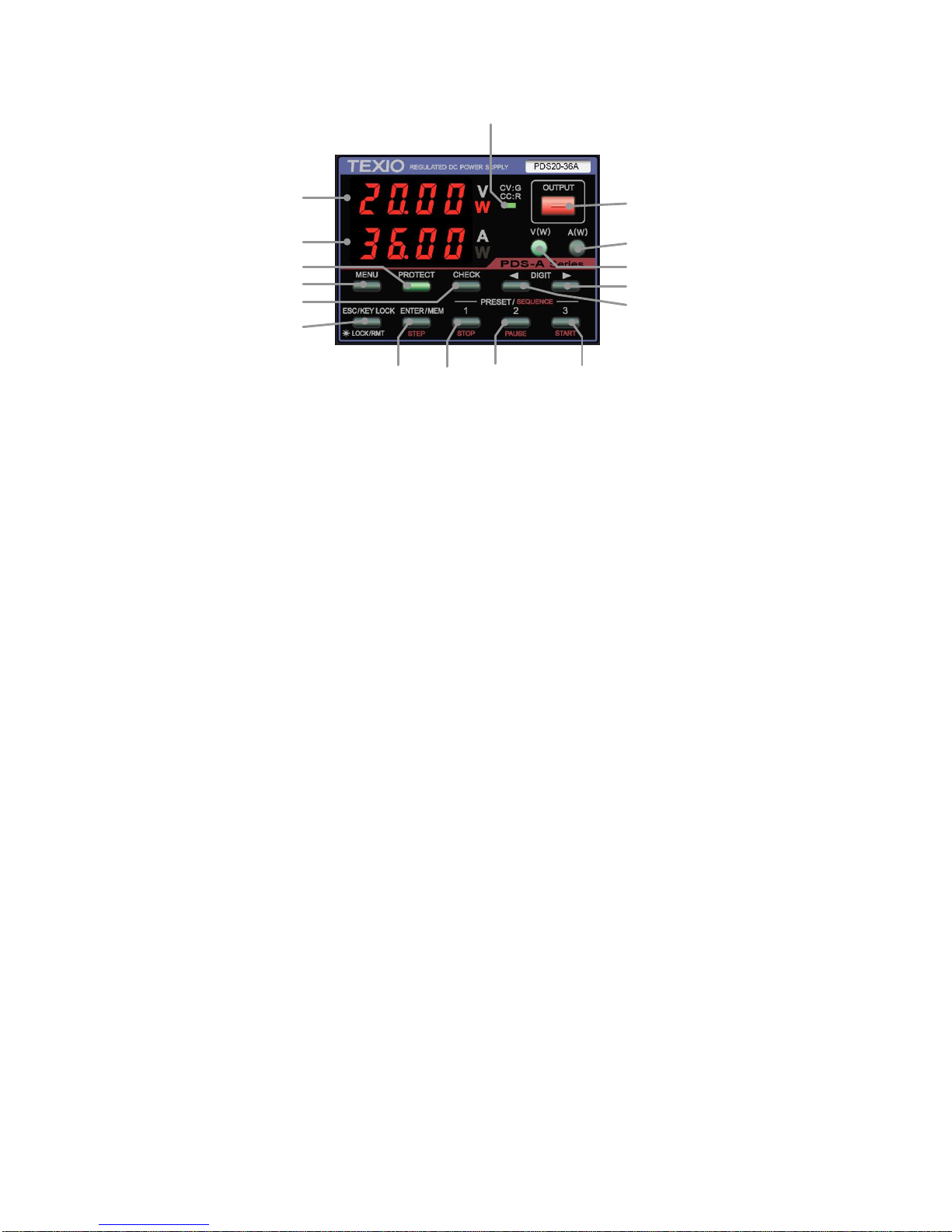
3-2. Operation Panel
6
7
13
12
14
21
17 18 19 20
8
9
11
10
15
16
Fig.3-2 Operation Panel
(The above figure shows the operation panel of the PDS20-36A.)
6. Voltage indicator (red LEDs): 4-digit display, unit indication
・ Indicates the set voltage, output voltage, output power, and MENU items.
・ “W” is lit in red when the indicator displays the output power.
7. Current indicator (red LEDs): 4-digit display, unit indication
・ Indicates the set current, output current, output power, and MENU items.
・ “W” is lit in red when the indicator displays the output power.
8. CV/CC LED (green/red)
・ When the output is on, the LED is lit in green when CV is in operation, and red when CC is in operation.
・ Turns off when output is off. It blinks red when the CC priority mode is selected.
9. OUTPUT key (red/amber)
Manual operation
・ Lit in red when the output is on.
・ Alternately blinks red and amber when the output off timer is set and the output is on.
・ Pressing this key turns the output on and off.
・ It is not possible to turn the output on and off when the MENU key is lit in green.
Sequence operation
・ If this key is pressed while a sequence manual/automatic operation is being executed, the output will turn off and
the sequence will be interrupted.
10. V key (green/amber)
The voltage is set by operating this front panel key
・ Pressing this key causes it to turn off or light in green.
・ When this key is lit in green, it is possible to change the blinking digit of the set voltage in the voltage indicator.
・ Pressing and holding down this key switches the voltage display to the power display. Pressing and holding
down this key again switches the display back to the voltage display.
・ The key is lit in amber when the voltage is set by external analog signals.
11. A key (green/amber)
The current is set by operating this front panel key
・ Pressing this key causes it to turn off or light in green.
・ When the key is lit in green, it is possible to change the blinking digit of the set current in the current indicator.
・ Pressing and holding down this key switches the current display to the power display. Pressing and holding
down this key again switches the display back to the current display.
・ The key is lit in amber when the current is set by external analog signals.

10
10
12. MENU key (green)
Manual operation
・ Able to operate and confirm the MENU setting or selection when this key is lit in green.
・ Unable to configure the MENU setting when the output is on.
Sequence operation
・ This key lights in green when it is pressed, and the voltage and current indicators display the setting of the
sequence steps to be executed.
13. PROTECT key (green)
・ Pressing this key when it is turned off sets OVP (over-voltage protection).
・ When this key is lit, OVP (over-voltage protection), UVP (under-voltage protection), and OCP (over-current
protection) can be selected and set. Press the ESC key to finish setting the protections.
14. CHECK key (green)
Manual operation
・ When this key is lit, the voltage and current indicators display the set voltage and current. When it is not lit, the
indicators display the output voltage and current.
In the power indication, the voltage and current indicators display "- - - -".
・ Pressing this key displays the output voltage/current and the set voltage/current alternately.
Operate the MENU key to display the output voltage and current when the output is off.
Sequence operation
・ Changes the voltage and current indicators from the sequence steps to the output voltage and current, and vice
versa.
・ The sequence steps are displayed when this key is lit, and the output voltage and current are displayed when it is
not lit.
15. DIGIT KEY ▲
Manual operation
・ Pressing this key moves the digit of the set voltage, current, OVP, UVP, or OCP value to be changed to the left.
Sequence operation
・ Returns to the previous step while the sequence program is being executed.
・ If this key is pressed when execution is stopped, the execution STEP can be set to the START STEP (execution
mode: 0 and 1) and the END STEP (execution mode: 2 and 3) in the sequence program.
16. DIGIT KEY ▼
Manual operation
・ Pressing this key moves the digit of the set voltage, current, OVP, UVP, or OCP value to be changed to the right.
Sequence operation
・ Moves forward to the next step while the sequence program is being executed.
・ If this key is pressed when execution is stopped, the execution STEP can be set to the END STEP (execution
mode: 0 and 1) and the START STEP (execution mode: 2 and 3) in the sequence program.
17. ENTER/MEM/STEP key (green/amber)
Manual operation
・ Memory function : Pressing this key causes the PRESET 1, 2, and 3 keys to blink, and places the memory on
standby to store the setting.
Pressing this key again cancels the memory’s standby state.
・ Initialization : Pressing and holding down this key then turns power on the unit and initializes the data
stored in the unit.
Sequence operation
• This key lights in green. Pressing this key again causes it to light in amber, and the voltage and current
indicators display the STEP value.

11
11
18. PRESET 1/STOP key (green/amber)
Manual operation
・ Stores and reads out the set voltage and current.
・ When this key blinks green, it is on standby to store the setting. When it is lit in green, it reads out the data
stored in PRESET 1.
Sequence operation
・ Lit in amber during the sequence operation. Pressing this key stops the execution of the sequence program.
19. PRESET 2/PAUSE key (green/amber)
Manual operation
・ Stores and reads out the set voltage and current.
・ When the key blinks green, it is on standby to store the setting. When it is lit green, it reads out the data stored
in PRESET 2.
Sequence operation
・ Lit in amber during the sequence operation. Pressing this key suspends the execution of the sequence program.
20. PRESET 3/START key (green/amber)
Manual operation
・ Stores and reads out the set voltage and current.
・ When the key blinks green, it is on standby to store the setting. When it is lit in green, it reads out the data
stored in PRESET 3.
Sequence operation
・ Lit in amber during the sequence operation. Pressing this key starts the execution of the sequence program.
21. ESC/KEYLOCK LOCK/RMT key (green)
・ Lit in green when the unit is in remote operation or key lock state. When this key is lit, the unit cannot be operated
from the front panel (although the OUTPUT key can still be operated).
・ ESC function: Pressing this key cancels the display of the voltage/current setting, OVP/UVP/OCP setting, MEMORY
setting, and MENU setting.
・ Pressing and holding this key while it is lit in green cancels remote operation or key lock. After remote operation or
key lock is cancelled, the light turns off.
・ Pressing and holding this key while the light is off locks the key. After the key is locked it lights in green.
12
12
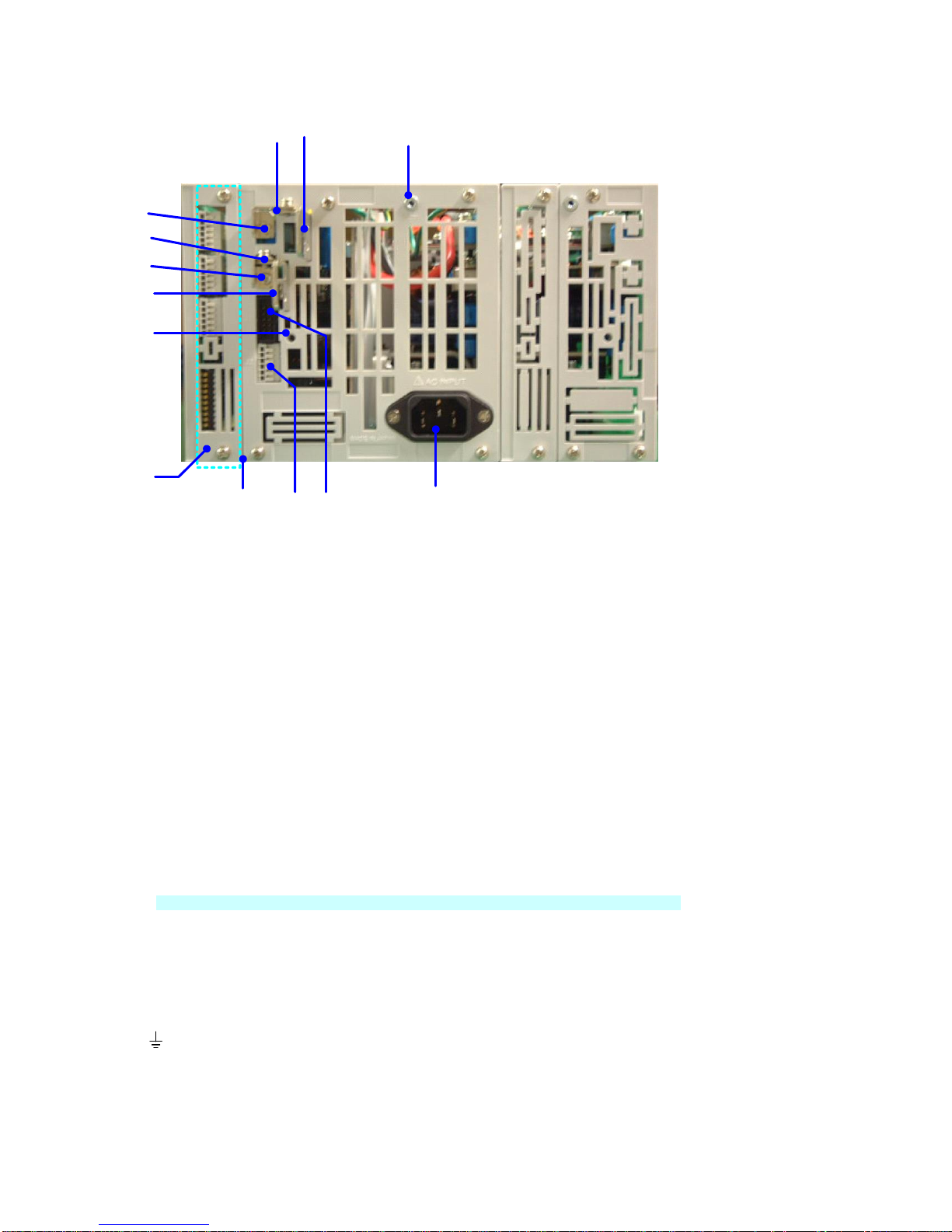
3-3. Rear Panel
2822
23
29
32
33
31 30
26
24
27
25
34
(bottom)
Fig. 3-3 Rear Panel
(The above figure shows the rear panel of the PDS20-36A (720W model).)
22,23. Output terminals
・ Output terminals of the PDS-A series power supply unit. 22: Positive output, 23: Negative output
Use the supplied bolt set when connecting to the load cable.
・ Voltage is output from the rear output terminals even when the front output terminals are used.
Be sure to attach the supplied rear output terminal cover to the unit when the rear output terminals are used.
The rear output terminal cover should be fixed at the following two points: the output terminal grounding terminal
(28) and the output terminal cover attachment hole (29)
24,25. Remote sensing terminals
・ Remote sensing terminals of the PDS-A series power supply unit. 24: Positive terminal, 25: Negative terminal
To use the remote sensing function, remove the shorting bars (26 and 27).
・ When using the remote sensing function, connect the positive remote sensing terminal (24) to the part where the
positive output terminal of the load is connected, and the negative remote sensing terminal (25) to the part where
the negative output terminal of the load is connected.
Incorrectly connecting the terminals may damage the unit or apply overvoltage to the load.
26,27. Shorting bars
Short-circuits the output terminals and remote sensing terminals.
25: Positive shorting bar 26: Negative shorting bar
When the remote sensing function is not used, attach the shorting bars to the output terminals and remote sensing
terminals to operate the unit. Failure to securely attach the short bar may cause the output to become unstable.
28. Output grounding terminal
・ Used to ground the positive or negative output terminal of the unit.
Use the output ground cable to ground output terminals.
・ This terminal is also used to fix the output terminal cover.
13
13
29. Output terminal cover attachment hole
・ Used to fix the output terminal cover.
Use the supplied M3 Large screws with washers.
30. J1 connector
・ Used for master-slave operation.
The parallel master-slave cable and series master-slave cable are different. Use the cable appropriate for the
operation.
CAUTION
!
Do not connect any cables other than the master-slave cable.
Connecting other cables may damage the unit.
31. J2 connector
・ The connector for the monitor output of the unit output and the slave control signal input for series master-slave
operation.
The terminal is a screw-less connector.
Use AWG24 – 26 cables to connect.
No.
Description
1
Output current monitor output: Output current 0A → Rated current approx.0V → Output 10V.
2
Output voltage monitor output: Output voltage 0V → Rated voltage approx. 0V → Output 10V.
3
Common terminal for 1 and 2. The terminal is connected to the negative output terminal.
4
When the unit is used as the slave machine for series master-slave operation, connect to the negative
output terminal of the master machine.
5,6
Not used. Do not connect anything to these terminals because they are for internal connection.
Fig3-4. J2 connector’s pin No.
32. Interface slot
・ An analog signal control unit (hereinafter standard board) is equipped as standard.
・ The standard board can be replaced with an interface board (hereinafter IF board) that controls the unit via external
signals.
Remove the two upper and lower screws from the marked area to install the IF board. Make sure to refasten the
two upper and lower screws after installing the board.
If the upper and lower screws are not fastened, contact failure between the unit and IF board may cause the unit to
malfunction.
J2
14
14
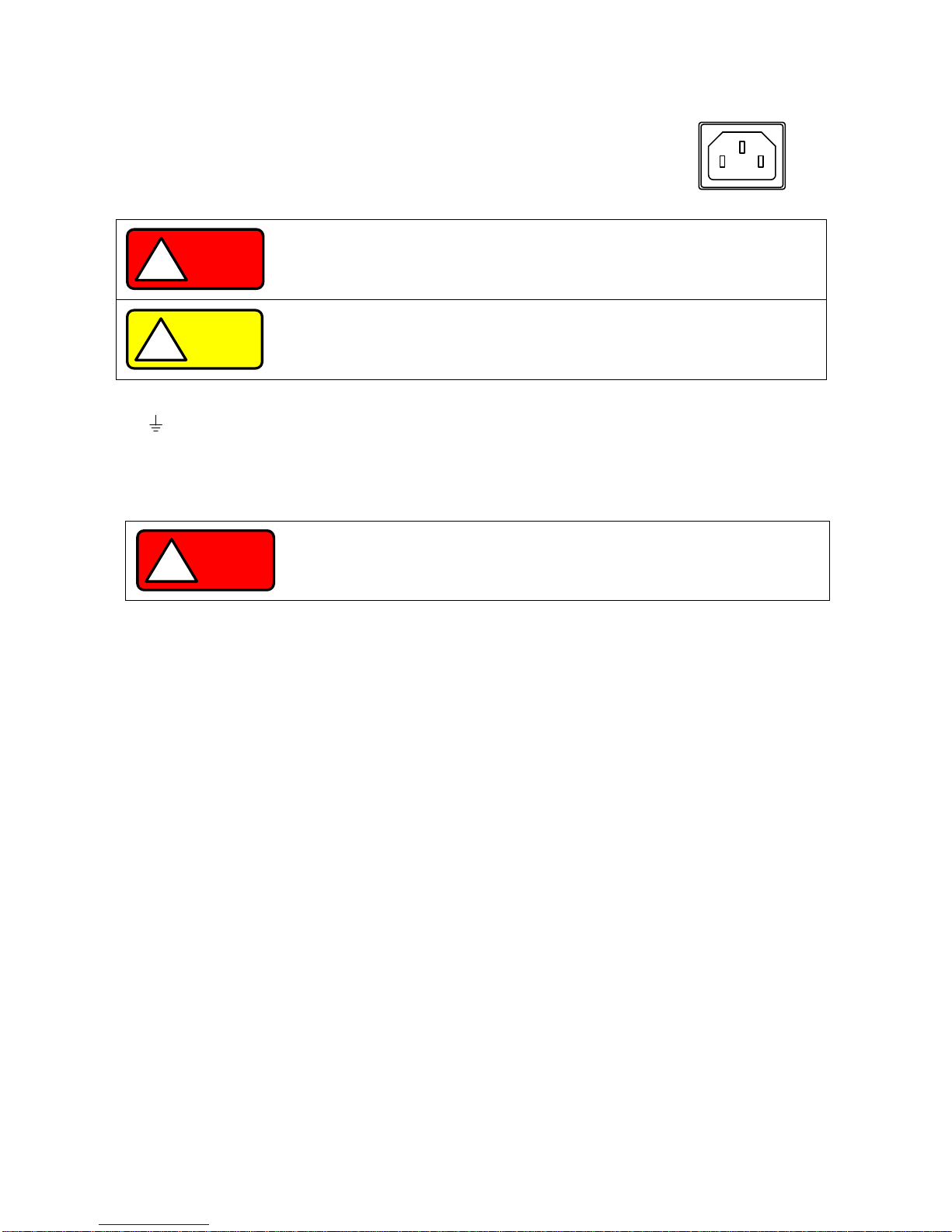
33. AC inlet
・ Use the supplied power cable. Connect the power cable to the AC outlet.
・ If the supplied power cable is used, the AC input voltage range of the unit will be
125V or lower (products for Japan only).
34. Protective grounding terminal
The product is equipped with a protective grounding terminal on the bottom face. For your own safety, make sure to
connect the unit to ground before use.
◆ See “2-5. Connecting the protective grounding terminal on the bottom face” for details.
AC inlet
WARNING
!
Supplying AC power to the unit that exceeds the specified input range may result in
failure, electric shock, or fire.
Performing wiring work while the power cable is connected to the AC outlet or
distribution panel may result in electric shock or fire.
CAUTION
!
For optimal air ventilation, maintain a distance of at least 30cm between the rear
panel and nearby objects.
If the rear panel is blocked, the internal temperature may rise.
WARNING
!
Make sure to properly connect the protective grounding terminal on the bottom face.
Failure to do so may result in electric shock.
If you do not connect the protective grounding terminal on the bottom face, it will
come off from the CE conformity.
15
15
4. GENERAL INSTRUCTIONS
4-1. Connecting loads
・ When connecting loads to the unit, use round crimp-style terminals, etc. to ensure loads are securely connected to
the output terminals.
・ Use cables that have sufficient current capacity for the wiring to be connected.
・ Be sure to turn off the unit (output off) before connecting or disconnecting cables to and from the wiring.
・ The unit is equipped with a capacitor of several thousands of μF that is connected to output terminals, and a
circuit for discharging the charged capacitor while the unit is turned off (output off).
The unit also features the HI-R function for cutting off the discharge circuit. However, low-ampere current flows
through the circuit of the voltage monitor, etc. When the battery is charged and the unit is turned off (output off),
the low-ampere current causes the voltage of the battery to fall.
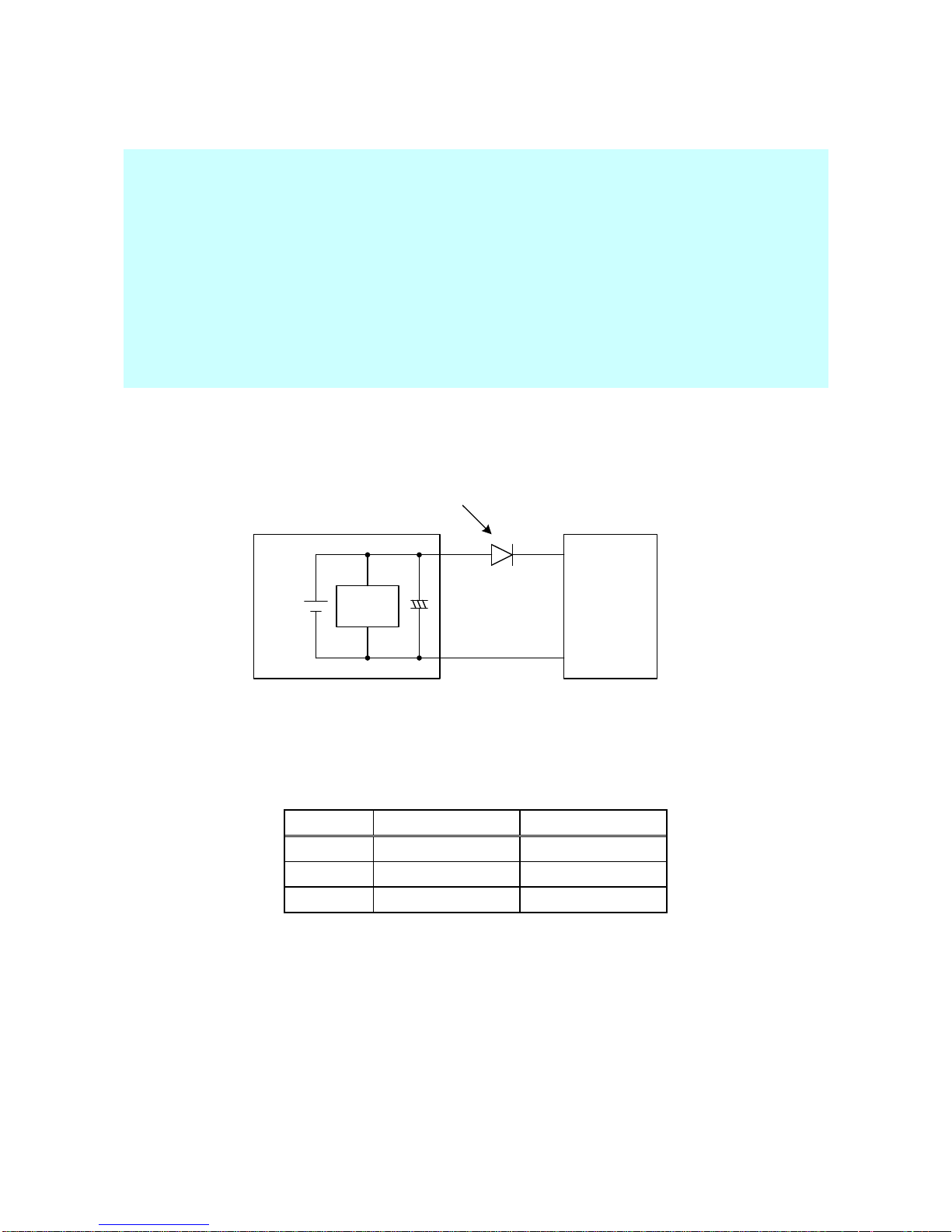
When the unit is used for charging batteries or a similar purpose, to prevent the load from discharging to the unit,
connect a diode in series to the load, as shown in Fig. 4-1 “Connecting load with energy”.
Voltage
Monitor
Load
(Battery, etc.)
+
-
PS-A
Power
Supply
Unit
+
Connect a diode that meets the following conditions:
・ It must have sufficient reverse voltage resistance against the rated voltage of the unit.
・ It must have sufficient forward current capacity against the rated current of the unit.
・ Take proper measures for the radiating heat generated by the elements.
-
Fig. 4-1 Connecting load with energy
Current capacity of load cable
The cable used as a load cable must have sufficient current capacity against the rated output current of the unit
AWG
Sectional area mm2
Recommended A
14 2 10 1 38
100
3/0
80
200
(Reference values at an ambient temperature of 30°C.)
PDS-A
16
16
4-2. Alarm
The hardware detects abnormal states and displays “AC oFF” or “ALП” on the voltage and current indicators.
Alarm causes
Cause
Recoverable
1
Over input voltage: Supply voltage of 270VAC or greater
No
2
Under input voltage: Supply voltage of 80VAC or less
No
3
Wrong number of power units used in parallel master-slave operation
No
4
Front output over current: Current from the front output is 30A or greater
Yes
5
Internal overheat: Internal heat sink temperature of approx. 110°C or higher
Yes
6
Over output voltage: 115% of maximum voltage or greater
Yes
7
Over output current: 115% of maximum current or greater
Yes
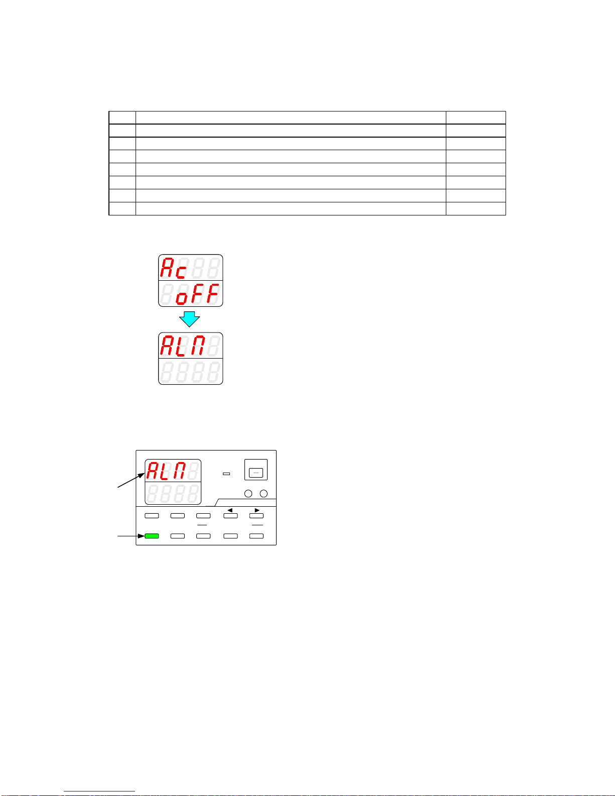
●Unrecoverable alarm
A
V
W
W
A
V
W
W
If the voltage and current indicators display “AC oFF”
and then “ALП”, and the power switch has not been
turned off, there may be a unit malfunction. Perform
the following steps:
1.
Turn off the power switch.
2.
Disconnect the power cable from the AC outlet or
distribution panel.
3.
Check whether any of the causes described in 1
through 3 have occurred.
● Recoverable alarm
A
V
W
W
CC:R
CV:G
OUTPUT
V(W) A(W)
MENU PROTECT CHECK
ESC/ KEY LOCK ENTER/ MEM
1 2 3
DIGIT
PRESET/ SEQUENCE
* LOCK/RMT
STEP STOP PAUSE START
PDS-A series
If the voltage indicator displays “ALП”, and the ESC key
is lit in green, press the ESC key.
This makes it possible to turn the power of the unit on or
off.
Check whether any of the causes described in 4 through
8 have occurred.
If the cause of the alarm was one of the causes described
in 6 through 8, the unit may need to be repaired or
recalibrated.

17
17
5. FUNCTIONS AND OPERATION PROCEDURES
5-1. Operation modes
The unit has four basic operation modes, which are as follows:
Operation Mode
Description
Manual mode
Setting by manual operation on the panel.
Sequence mode
Setting changes over time according to the sequence program stored in the internal
memory.
External analog control
Setting via external analog signals and ON/OFF signal.
External digital control
Setting via external communication device.
5-2. Turning On Power
5-2-1. Display when power is turned on
Properly connect the AC power cable of the PDS-A power supply unit, confirm that power is being supplied, and then
turn on the power switch. The following characters are displayed on the voltage and current indicators until the unit is
ready for normal operation.
These characters are displayed after the power switch is turned on.
The rated voltage is displayed in the upper row, and the rated current in
the lower row. (The rating is displayed while the internal test is
performed.)
The software version is displayed.
When using a parallel connection, the version is displayed for 2 seconds.
The display then switches to the unit scan window.
The unit can be operated.
Manual mode.
The unit can be operated.
Sequence mode.
After displaying the seq mode, step No. is displayed.
5-2-2. Performing a unit scan while using a parallel connection
When a parallel connection is set up, the master unit checks the operation status of the slave units.
The voltage and current indicators display the following messages until the unit enters normal operation status.
A
V
W
W
CC:R
CV:G
OUTPUT
V(W) A(W)
MENU PROTECT CHECK
ESC/ KEY LOCKENTER/ 1 2 3
DIGIT
PRESET/ SEQUENCE
* LOCK/ RMT STEP STOP PAUSE START
PDS-A series
When a scan is performed while a parallel connection is being
used, the word "ScAn" is displayed on the voltage indicator.
The scanning status is displayed on the current indicator.
In the left figure, "0" indicates the number of scanned units,
and "2" indicates the number of registered units in the parallel
connection.
18
18
A
V
W
W
CC:R
CV:G
OUTPUT
V(W) A(W)
MENU PROTECT CHECK
ESC/ KEY LOCKENTER/ 1 2 3
DIGIT
PRESET/ SEQUENCE
* LOCK/ RMT STEP STOP PAUSE START
PDS-A series
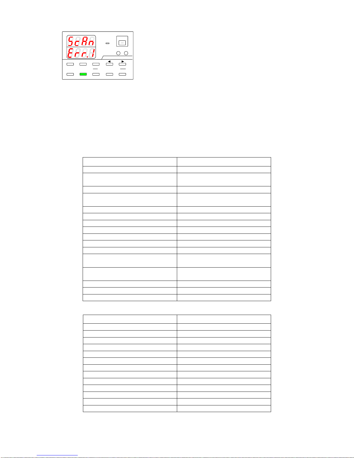
If the unit detects a number other than the number of
registered units, an error message is displayed, as shown in
the figure on the left.
The final digit of the current indicator indicates the number of
units detected, including the master unit.
In the figure on the left figure, the number listed in the error
message is "1". This number indicates that the master unit
was detected, but no slave units.
If this error message is displayed, check the settings and
wiring, and then restart the power supply unit.
5-2-3. Recalling Settings When Turning on Power, and Saving the Setting Data
The PDS-A power supply unit saves setting data in a non-volatile memory when the unit is turned off, or before the
power is cut. The settings are recalled when the unit is turned on. The default settings and the settings after
initializing the memory for the stored setting items are shown below.
Table 5-1. Stored setting items: Manual mode
Manual mode
Initial setting
Sequence mode
Off
Preset data recalled when power is
turned on
Last
Output Off display
Set value
Output On setting when power is turned
on
Off
Master-slave
Single-unit operation
CC priority output
Off
Output Off timer
0 min.
Setting cancellation time
3 min.
Set OVP
Maximum
Set UVP
Minimum
Set OCP
Maximum
Set voltage
(including stored Preset voltages)
0V
Set current
(including stored Preset currents)
0A
System address
1
PC address
1
PC address configured via LAN
0
Table 5-2. Stored setting items: Sequence mode
Sequence mode
Initial setting
Set voltage for each step
0V
Set current for each step
0A
Output for each step
Off
OVP for each step
Maximum
UVP for each step
Minimum
OCP for each step
Maximum
Execution time for each step
00h00m00s000
Pause operation for each step
OFF
Output HI-R setting for each step
OFF
Start step
1
End step
1000
Number of repeating programs
1
Execution mode
0
※ A battery cell is not used to store setting data.
19
19
5-3. Basic Operation
5-3-1. Voltage setting procedure
A
V
W
W
CC:R
CV:G
OUTPUT
V(W) A(W)
MENU PROTECT CHECK
ESC/ KEY LOCK ENTER/ MEM
1 2 3
DIGIT
PRESET/ SEQUENCE
* LOCK/RMT
STEP STOP PAUSE START
1
2
3
Blinking
PDS-A series
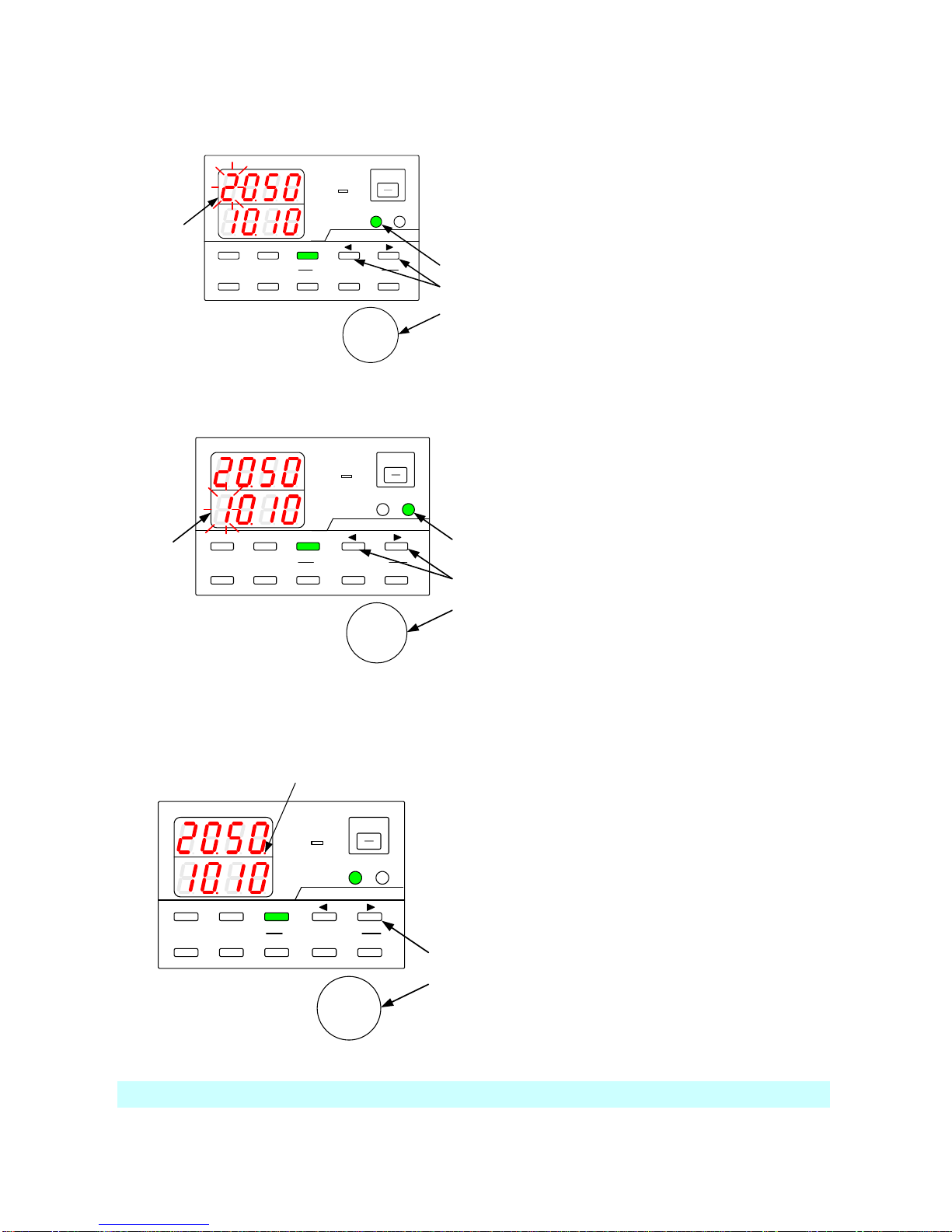
Operation procedure
1.
Press the V key, which is then lit in green.
One of the voltage setting digits starts blinking.
Only the digit that is blinking can be modified.
2.
Press one of the DIGIT keys ▲ ▼ to move to
another digit and make it blink.
3.
Use the setting rotary encoder to set the voltage
value.
4.
Press the V key to exit the setting mode.
5-3-2. Current setting procedure
A
V
W
W
CC:R
CV:G
OUTPUT
V(W) A(W)
MENU PROTECT CHECK
ESC/ KEY LOCK ENTER/ MEM
1 2 3
DIGIT
PRESET/ SEQUENCE
* LOCK/ RMT
STEP STOP PAUSE START
1
2
3
Blinking
PDS-A series
Operation procedure
1.
Press the A key, which is then lit in green.
One of the current setting digits starts blinking.
Only the digit that is blinking can be modified.
2.
Press one of the DIGIT keys ▲ ▼ to move to
another digit and make it blink.
3.
Use the setting rotary encoder to set the current
value.
4.
Press the A key to exit the setting mode.
5-3-3. Fine adjustment of voltage/current
Function: Fine-adjusting the output voltage/current to a digit lower than the displayed digits
Blinking
A
V
W
W
CC:R
CV:G
OUTPUT
V(W) A(W)
MENU PROTECT CHECK
ESC/ KEY LOCK ENTER/ MEM
1 2 3
DIGIT
PRESET/ SEQUENCE
* LOCK/RMT
STEP STOP PAUSE START
1
2
PDS-A series
Operation procedure
1.
Confirm that the rightmost digit is blinking, and
press the DIGIT key ▼ to move the modifiable
digit to the right.
The rightmost digit stops blinking and then
remains lit.
2.
With the rightmost digit lit, turn the setting
rotary encoder to adjust the voltage/current to
one digit lower than the lowest displayed digit.
The digit lower than the displayed digit is not
visible. You must connect an external device to
confirm the actual output. Note that the amount
of change made by one click of the rotary
encoder might differ by model.
The setting accuracy in SPECIFICATIONS is not guaranteed for fine adjustment.
20
20
5-4. Output Functions
CC:R
CV:G
OUTPUT
1
2
CC:R
CV:G
OUTPUT
CC:R
CV:G
OUTPUT
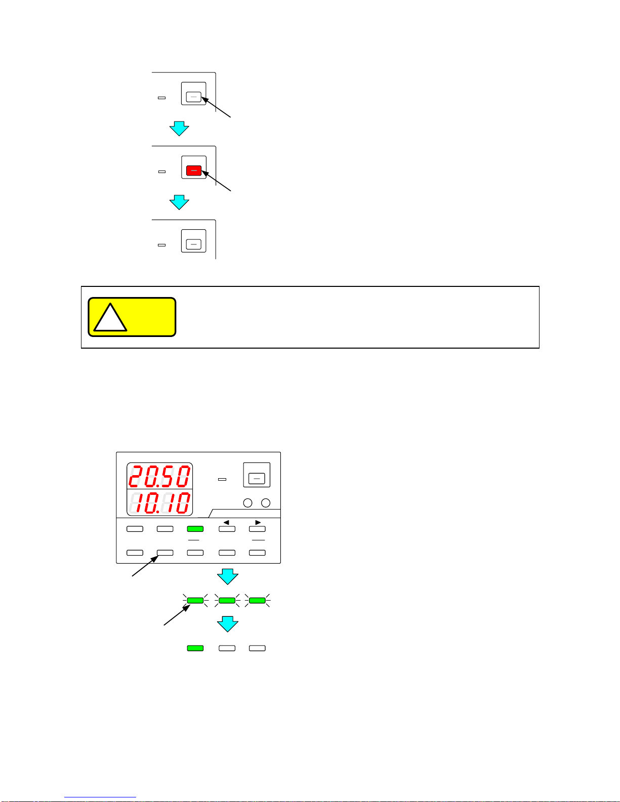
Operation procedure
1.
Press the unlit OUTPUT key, which is then lit
in red. After this key is lit, voltage is output.
2.
Press the red-lit OUTPUT key. The light goes out,
and the voltage output is turned off.
CAUTION
!
Make sure the wires are connected to the output terminals before turning the output
on.
5-5. Memory Function
5-5-1. Storing and recalling preset voltage/current data
● Storing preset data
A
V
W
W
CC:R
CV:G
OUTPUT
V(W) A(W)
MENU PROTECT CHECK
ESC/ KEY LOCK ENTER/ MEM
1 2 3
DIGIT
PRESET/ SEQUENCE
* LOCK/RMT
STEP STOP PAUSE START
1
1 2 3
STOP PAUSE START
2
1 2 3
STOP PAUSE START
PDS-A series
Operation procedure
1.
Set the voltage and current values, following the
steps described in
“5-3-1. Voltage setting procedure”
“5-3-2. Current setting procedure”
Press the ENTER/MEM key.
PRESET keys 1 to 3 all blink green.
2.
Press the PRESET key (1, 2, or 3) where you
want to store the set value.
The PRESET key you pressed lights in green.
The voltage and current values are stored in the
selected PRESET key.
※ To cancel storing the set values, press the
ENTER/MEM key again while PRESET
keys 1 to 3 are all blinking green.
21
21
● Recalling preset data
A
V
W
W
CC:R
CV:G
OUTPUT
V(W) A(W)
MENU PROTECT CHECK
ESC/ KEY LOCK ENTER/ MEM
1 2 3
DIGIT
PRESET/ SEQUENCE
* LOCK/RMT
STEP STOP PAUSE START
1
PDS-A series
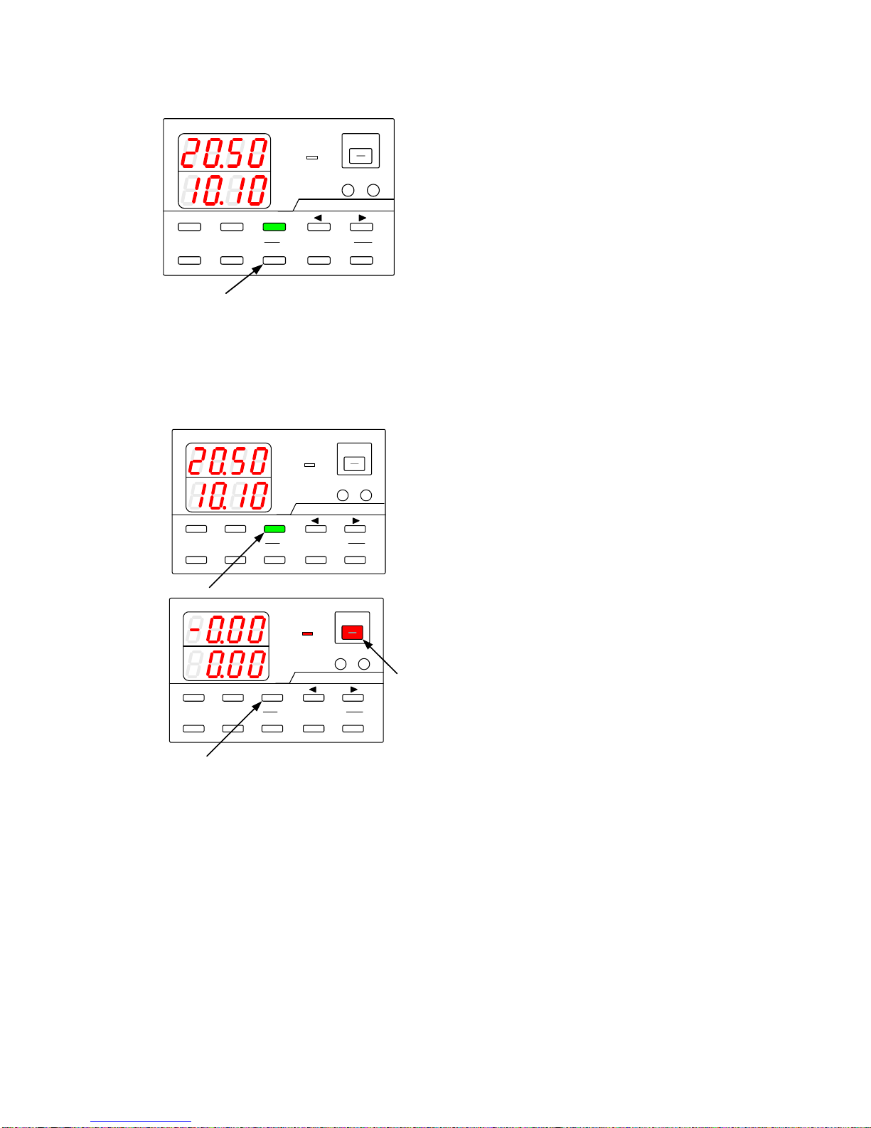
Operation procedure
1.
Press a PRESET key (1, 2, or 3) to recall the
voltage and current values stored in that key.
5-6. Switching the display in the Voltage/Current Indicator Display.
5-6-1. Switching between the set voltage/current display and output voltage/current display
A
V
W
W
CC:R
CV:G
OUTPUT
V(W) A(W)
MENU PROTECT CHECK
ESC/ KEY LOCK ENTER/ MEM
1 2 3
DIGIT
PRESET/ SEQUENCE
* LOCK/ RMT
STEP STOP PAUSE START
PDS-A series
A
V
W
W
CC:R
CV:G
OUTPUT
V(W) A(W)
MENU PROTECT CHECK
ESC/ KEY LOCK ENTER/MEM
1 2 3
DIGIT
PRESET/ SEQUENCE
* LOCK/ RMT
STEP STOP PAUSE START
PDS-A series
Operation procedure
When the CHECK key is lit in green, the set
voltage and current are displayed.
When the CHECK key is unlit, the output
voltage and current are displayed.
When the output is off, the CHECK key remains
lit in green.
(No CHECK key operations can be performed.)
When the OUTPUT key is pressed and then lit in
red (turning the output on), the CHECK key light
goes out.

22
22
5-6-2. Displaying Power in the Voltage and Current Indicators
● Displaying output power in the voltage indicator:
A
V
W
W
CC:R
CV:G
OUTPUT
V(W) A(W)
A
V
W
W
CC:R
CV:G
OUTPUT
V(W) A(W)
MENU PROTECT CHECK
ESC/ KEY LOCK ENTER/ MEM
1 2 3
DIGIT
PRESET/ SEQUENCE
* LOCK/ RMT
STEP STOP PAUSE START
1
MENU PROTECT CHECK
ESC/ KEY LOCK ENTER/ MEM
1 2 3
DIGIT
PRESET/ SEQUENCE
* LOCK/ RMT
STEP STOP PAUSE START
A
V
W
CC:R
CV:G
OUTPUT
V(W) A(W)
MENU PROTECT CHECK
ESC/ KEY LOCK ENTER/ MEM
1 2 3
DIGIT
PRESET/ SEQUENCE
* LOCK/ RMT
STEP STOP PAUSE START
2
PDS-A series
PDS-A series
PDS-A series
Operation procedure
1.
When voltage is displayed, press and hold the V
key to display the output power.
When the output is off, the output power is
displayed as “----“.
Press and hold the unlit V key to display the
voltage again.
2.
Press the OUTPUT key to display the output power.

23
23
●Displaying output power in the current indicator:
A
V
W
W
CC:R
CV:G
OUTPUT
V(W) A(W)
MENU PROTECT CHECK
ESC/ KEY LOCK ENTER/MEM
1 2 3
DIGIT
PRESET/ SEQUENCE
* LOCK/ RMT
STEP STOP PAUSE START
1
A
V
W
W
CC:R
CV:G
OUTPUT
V(W) A(W)
MENU PROTECT CHECK
ESC/ KEY LOCK ENTER/MEM
1 2 3
DIGIT
PRESET/ SEQUENCE
* LOCK/ RMT
STEP STOP PAUSE START
A
V
W
W
CC:R
CV:G
OUTPUT
V(W) A(W)
MENU PROTECT CHECK
ESC/ KEY LOCK ENTER/MEM
1 2 3
DIGIT
PRESET/ SEQUENCE
* LOCK/ RMT
STEP STOP PAUSE START
2
PDS-A series
PDS-A series
PDS-A series
Operation procedure
1.
When current is displayed, press and hold the A
key to display the output power.
When the output is off, the output power is
displayed as “----“.
Press and hold the unlit A key to display the
current again.
2.
Press the OUTPUT key to display the output power.
When the V and A keys are lit, the display cannot be switched to the output power display.

24
24
5-7. Protective Functions
The PDS-A power supply unit has 3 different protective functions (OVP, UVP, and OCP). Set the value for each of the
protective functions to fit the intended use of the unit.
Function
Description
OVP
Turns the output off when the output voltage exceeds the set voltage for OVP.
UVP
Turns the output off when the output voltage falls below the set voltage for UVP.
OCP
Turns the output off when the output current exceeds the set current for OCP.
For the UVP and OCP functions, the software detects output voltage and current and turns the output
off if needed.
5-7-1. Display when protective functions are activated
A
V
W
W
CC:R
CV:G
OUTPUT
V(W) A(W)
MENU PROTECT CHECK
ESC/ KEY LOCK ENTER/MEM
1 2 3
DIGIT
PRESET/ SEQUENCE
* LOCK/RMT
STEP STOP PAUSE START
PDS-A series
A
V
W
W
CC:R
CV:G
OUTPUT
V(W) A(W)
MENU PROTECT CHECK
ESC/ KEY LOCK ENTER/MEM
1 2 3
DIGIT
PRESET/ SEQUENCE
* LOCK/RMT
STEP STOP PAUSE START
PDS-A series
A
V
W
W
CC:R
CV:G
OUTPUT
V(W) A(W)
MENU PROTECT CHECK
ESC/ KEY LOCK ENTER/MEM
1 2 3
DIGIT
PRESET/ SEQUENCE
* LOCK/RMT
STEP STOP PAUSE START
PDS-A series
OVP (Overvoltage protection)
UVP (Undervoltage protection)
OCP (Overcurrent protection)
5-7-2. Modification of the Set Values of Protective Functions
When modifying the set value of a protective function, press the PROTECT key and select the protective function to be
modified. Modify the set values by using the DIGIT keys ▲ ▼ and the rotary encoder.
4
A
V
W
W
CC:R
CV:G
OUTPUT
V(W) A(W)
MENU PROTECT CHECK
ESC/ KEY LOCK ENTER/MEM
1 2 3
DIGIT
PRESET/ SEQUENCE
* LOCK/RMT
STEP STOP PAUSE START
1
A
V
W
W
CC:R
CV:G
OUTPUT
V(W) A(W)
MENU PROTECT CHECK
ESC/ KEY LOCK ENTER/MEM
1 2 3
DIGIT
PRESET/ SEQUENCE
* LOCK/RMT
STEP STOP PAUSE START
3
2
PDS-A series
PDS-A series
Operation procedure
1.
Press the PROTECT key, which is then lit in
green. The protective function type is displayed
in the current indicator, and the modifiable digit
blinks in the voltage indicator.
2.
Press the DIGIT keys ▲ ▼ to select the digit to
be modified. Only the digit that is blinking can
be modified.
3.
Use the rotary encoder to modify the set value.
4.
After setting the protective function, press the
blinking ESC/KEY LOCK key to store the set
value of the protective function.
Press the green-lit PROTECT key to change the
display. The display changes in the following
order: OVP setting UVP setting OCP
setting.
A
V
W
W
A
V
W
W
A
V
W
W

25
25
5-7-3. Deactivating Protective Functions
When some protective functions are activated, it is displayed and the output is turned off.
A
V
W
W
CC:R
CV:G
OUTPUT
V(W) A(W)
MENU PROTECT CHECK
ESC/KEY LOCK ENTER/ MEM
1 2 3
DIGIT
PRESET/ SEQUENCE
* LOCK/ RMT
STEP STOP PAUSE START
1
PDS-A series
Operation procedure
1.
When the activated protection is displayed,
press the PROTECT key, which is blinking
green, to deactivate the protective function.
After deactivating the protective function, the
unit can be operated while output is off.
5-8. Key Lock / Local Function
Status
Non-operational keys
KEY LOCK
All keys, excluding the ESC/KEY LOCK key, OUTPUT key (only when turning the
output off), and the rotary encoder.
REMOTE
All keys, excluding the ESC/KEY LOCK key and rotary encoder.
5-8-1. Key lock and unlock procedures
● Key lock procedure
A
V
W
W
CC:R
CV:G
OUTPUT
V(W) A(W)
MENU PROTECT CHECK
ESC/ KEY LOCK ENTER/ MEM
1 2 3
DIGIT
PRESET/ SEQUENCE
* LOCK/ RMT
STEP STOP PAUSE START
1
ESC/ KEY LOCK
* LOCK/ RMT
PDS-A series
Operation procedure
1.
When the MENU key and the PROTECT key are
unlit, press and hold the ESC/KEY LOCK key,
which is then lit in green.
This activates key lock. After key lock is activated,
you cannot operate the keys and the rotary
encoder.
●Key unlock procedure
A
V
W
W
CC:R
CV:G
OUTPUT
V(W) A(W)
MENU PROTECT CHECK
ESC/ KEY LOCK ENTER/ MEM
1 2 3
DIGIT
PRESET/ SEQUENCE
* LOCK/ RMT
STEP STOP PAUSE START
1
ESC/ KEY LOCK
* LOCK/ RMT
PDS-A series
Operation procedure
2.
Press and hold the green-lit ESC/KEY LOCK
key. The light then goes out.
This deactivates key lock. After key lock is
deactivated, you can operate the keys and the
rotary encoder.
While key lock is activated, the output can be turned off.
However, if the output is already off, it cannot be turned on.

26
26
5-8-2. Remote mode deactivation procedure
A
V
W
W
CC:R
CV:G
OUTPUT
V(W) A(W)
MENU PROTECT CHECK
ESC/ KEY LOCK ENTER/ MEM
1 2 3
DIGIT
PRESET/ SEQUENCE
* LOCK/ RMT
STEP STOP PAUSE START
1
ESC/ KEY LOCK
* LOCK/ RMT
PDS-A series
Operation procedure
When the unit is operated via external digital
control, the ESC/KEY LOCK key is lit in green
and the unit is remotely controlled.
When the unit is remotely controlled, you cannot
operate the keys and the rotary encoder.
1.
Press and hold the green-lit ESC/KEY LOCK
key. The light then goes out.
This returns the unit to local mode. You can
operate the keys and the rotary encoder after the
unit returns to local mode.
Even if the unit is in local mode, it returns to remote mode when it is operated via external digital control.

27
27
6. SETTING WITH THE MENU KEY
● The following items can be set by using the MENU key:
Setting item
Explanation in the manual
Page
Setting the output off timer
6-1-1. Setting the output off timer
28
Specifying the automatic cancellation time of the
setting menu display
6-2. Specifying the automatic cancellation time of the setting
menu display
30
Confirming that output is off
9-2-6. Checking the status when the output is off
75
Confirming the interface card mode
11-1-4. Confirming the interface card mode
80
Push the MENU key to change the display. Items with no assigned functions are skipped.
Top Menu
OUTPUT OFF
Timer Setting
Specifying the Automatic
Cancellation Time for the
setting menu Display
Interface Card
Mode Display
System/PC
Address
Version Display
OUTPUT OFF
Status Confirmation
MENU KEY
● The following items can be set when turning on the power switch while pressing and holding the MENU key:
Setting item
Explanation in the manual
Page
Recalling preset values when the power is
turned on
6-3-1. Recalling preset values when the power is turned on
31
Setting the output when the power is turned on
6-3-2. Setting the output when the power is turned on
32
Setting the CC priority mode
6-3-3. Setting the CC priority mode
33
Setting the display while the output is off
6-3-4. Setting the display while the output is off
36
Configuring the master and slave units
7-1-1. Configuring the master and slave units
44
Setting sequence operation
8-1. Setting of Sequence Operation
50
Address settings
11-1-5. Address settings
81
RS-232C communication speed setting (while
IF-71RS is in full-duplex mode)
6-3-6. Specifying the baud rate while in IF-71RS PDS
mode
40
Specifying power relay ON/OFF (with remote IF)
6-3-5. Default setting of the power relay when power is
turned on
39
Push the MENU key to change the display. Items with no assigned functions are skipped.
Top Menu
SYSTEM
ADDRESS
PDS MODE
COMMUNICATIN
SPEED
MENU KEY
Automatic
Sequence start
Presetting at
Power on
CV/CC Priority
Setting
Output Setting at
Power on
Master/Slave
Setting
Power Relay
Defalt setting
Display Setting
at Output off
Number of parallel
Slave Units
PC
ADDRESS
Enter key Enter key
● The following items can be set when turning on the power switch while pressing and holding the ENTER/MEM key:
Setting item
Explanation in the manual
page
Memory clear
6-4. Clearing the Memory
39

28
28
6-1. Output Off Timer
This function is used to automatically turn off the output after a preset amount of time has passed since the
output was turned on.
6-1-1. Setting the output off timer
A
V
W
W
CC:R
CV:G
OUTPUT
V(W) A(W)
MENU PROTECT CHECK
ESC/ KEY LOCK ENTER/ MEM
1 2 3
DIGIT
PRESET/ SEQUENCE
* LOCK/ RMT
STEP STOP PAUSE START
1
PDS-A series
A
V
W
W
CC:R
CV:G
OUTPUT
V(W) A(W)
MENU PROTECT CHECK
ESC/ KEY LOCK ENTER/ MEM
1 2 3
DIGIT
PRESET/ SEQUENCE
* LOCK/ RMT
STEP STOP PAUSE START
2
3
4
PDS-A series
A
V
W
W
CC:R
CV:G
OUTPUT
V(W) A(W)
MENU PROTECT CHECK
ESC/ KEY LOCK ENTER/ MEM
1 2 3
DIGIT
PRESET/ SEQUENCE
* LOCK/RMT
STEP STOP PAUSE START
4
5
PDS-A series
Operation procedure
1.
Turn the output off, then repeatedly press the
MENU key until the current indicator displays “*
*.oF” .
The MENU key is then lit in green, and the
ESC/KEY LOCK key and the ENTER/MEM key
start blinking green.
2.
Press the DIGIT keys to select the digit to
be modified. Only the digit that is blinking can
be modified.
Press the DIGIT keys a few times to move
the blinking digit from the voltage indicator to the
current indicator.
3.
Use the rotary encoder to specify the desired
setting.
The hours are set in the voltage indicator, and
the minute are defined in the current indicator.
In the left figure, the output off timer is set for 2
hrs. and 20 min.
The timer range is from 1 min. to 1000 hrs. and
59 min, and can be adjusted in 1 min. increments.
Specifying 0 min. for the timer deactivates the
output off timer function.
4.
Press the green-blinking ENTER/MEM key to
enter the setting.
After the setting is entered, the current indicator
stops blinking, remains lit for a short while, and
then starts blinking again.
5.
Press the green-blinking ESC/KEY LOCK key to
exit.
Normal operation of the unit is then available.
This setting must be specified while the output is off.

29
29
6-1-2. Operating the output off timer
A
V
W
W
CC:R
CV:G
OUTPUT
V(W) A(W)
MENU PROTECT CHECK
ESC/ KEY LOCK ENTER/MEM
1 2 3
DIGIT
PRESET/ SEQUENCE
* LOCK/ RMT
STEP STOP PAUSE START
1
2
PDS-A series
A
V
W
W
CC:R
CV:G
OUTPUT
V(W) A(W)
MENU PROTECT CHECK
ESC/ KEY LOCK ENTER/ MEM
1 2 3
DIGIT
PRESET/ SEQUENCE
* LOCK/RMT
STEP STOP PAUSE START
PDS-A series
Operation procedure
1.
Press the OUTPUT key to turn the output on.
The CV/CC LED is lit in green when the output
on status is CV, and red when it is CC.
If the output off timer has been set for a certain
amount of time, the OUTPUT key is alternately lit
in red and amber.
2.
Press the MENU key, which is then lit in green.
This starts the countdown for the set time
specified in “6-1-1. Setting the output off timer”.
After the set time has passed, the OUTPUT key
light goes out, and the output is turned off.

30
30
6-2. Specifying the automatic cancellation time of the setting menu display
Specifies the time to cancel the setting automatically after the PDS-A unit has been left alone for a certain amount of
time in each setting menu (voltage, current, OVP, UVP, and OCP).
A
V
W
W
CC:R
CV:G
OUTPUT
V(W) A(W)
MENU PROTECT CHECK
ESC/ KEY LOCK ENTER/ MEM
1 2 3
DIGIT
PRESET/ SEQUENCE
* LOCK/ RMT
STEP STOP PAUSE START
1
PDS-A series
A
V
W
W
CC:R
CV:G
OUTPUT
V(W) A(W)
MENU PROTECT CHECK
ESC/ KEY LOCK ENTER/ MEM
1 2 3
DIGIT
PRESET/ SEQUENCE
* LOCK/RMT
STEP STOP PAUSE START
2
PDS-A series
A
V
W
W
CC:R
CV:G
OUTPUT
V(W) A(W)
MENU PROTECT CHECK
ESC/ KEY LOCK ENTER/ MEM
1 2 3
DIGIT
PRESET/ SEQUENCE
* LOCK/ RMT
STEP STOP PAUSE START
34
PDS-A series
Operation procedure
1.
Turn the output off, then repeatedly press the
MENU key until "ESC" is displayed in the voltage
indicator.
The MENU key is then lit in green, and the
ESC/KEY LOCK key and the ENTER/MEM key
start blinking green.
The function name is displayed in the voltage
indicator, and the function setting is displayed
(blinking) in the current indicator.
2.
Turn the rotary encoder to set the display time,
which is displayed in the current indicator.
The display time range is from 0 min. to 10 min.,
and can be adjusted in 1 min. increments.
(If 0 min. is set for the display time, the setting
display is not disabled automatically.)
3.
Press the green-blinking ENTER/MEM key to
enter the setting.
After the setting is entered, the current indicator
stops blinking, remains lit for a short while, and
then starts blinking again.
4.
Press the green-blinking ESC/KEY LOCK key to
exit.
Normal operation of the unit is then available.

31
31
6-3. Specifying Settings when the Power Is Turned On
6-3-1. Recalling preset values when the power is turned on
The voltage and current values can be set when the power is turned on.
The voltage and current values that can be selected are the set values from when power was last turned off, and the data
stored in PRESET keys 1, 2, and 3.
1
A
V
W
W
CC:R
CV:G
OUTPUT
V(W) A(W)
MENU PROTECT CHECK
ESC/ KEY LOCK ENTER/ MEM
1 2 3
DIGIT
PRESET/ SEQUENCE
* LOCK/RMT
STEP STOP PAUSE START
PDS-A series
A
V
W
W
CC:R
CV:G
OUTPUT
V(W) A(W)
MENU PROTECT CHECK
ESC/ KEY LOCK ENTER/ MEM
1 2 3
DIGIT
PRESET/ SEQUENCE
* LOCK/ RMT
STEP STOP PAUSE START
3
2
PDS-A series
A
V
W
W
CC:R
CV:G
OUTPUT
V(W) A(W)
MENU PROTECT CHECK
ESC/KEY LOCK ENTER/ MEM
1 2 3
DIGIT
PRESET/ SEQUENCE
* LOCK/RMT
STEP STOP PAUSE START
45
PDS-A series
A
V
W
W
Operation procedure
1.
Turn on the power switch while pressing and
holding the MENU key.
Release the MENU key when the panel is lit.
The MENU key is then lit in green, and the
ESC/KEY LOCK key and the ENTER/MEM key
start blinking green.
The function name is displayed in the voltage
indicator, and the function setting is displayed
(blinking) in the current indicator.
2.
Repeatedly press the MENU key until "PrSt" is
displayed in the current indicator.
3.
Turning the rotary encoder displays the following.
Select the values you want to recall.
A
W
The set values from when the
power last turned off.
A
W
The values stored in the
PRESET 1 key.
A
W
The values stored in the
PRESET 2 key.
A
W
The values stored in the
PRESET 3 key.
4.
Press the green-blinking ENTER/MEM key to
enter the setting.
After the setting is entered, the current indicator
stops blinking, remains lit for a short while, and
then starts blinking again.
5.
Press the green-blinking ESC/KEY LOCK key to
exit. The message shown in the figure on the
left appears. Normal operation of the unit is
then available.
Turn the power switch off and then back on to
reflect the selected PRESET values.

32
32
6-3-2. Setting the output when the power is turned on
When the power is turned on, the PDS-A power supply unit can turn the output on, without needing to push the
OUTPUT key.
A
V
W
W
CC:R
CV:G
OUTPUT
V(W) A(W)
MENU PROTECT CHECK
ESC/ KEY LOCK ENTER/ 1 2 3
DIGIT
PRESET/ SEQUENCE
* LOCK/RMT STEP STOP PAUSE START
PDS-A series
1
A
V
W
W
CC:R
CV:G
OUTPUT
V(W) A(W)
MENU PROTECT CHECK
ESC/ KEY LOCK ENTER/ MEM
1 2 3
DIGIT
PRESET/ SEQUENCE
* LOCK/ RMT
STEP STOP PAUSE START
3
2
PDS-A series
A
V
W
W
CC:R
CV:G
OUTPUT
V(W) A(W)
MENU PROTECT CHECK
ESC/KEY LOCK ENTER/ MEM
1 2 3
DIGIT
PRESET/ SEQUENCE
* LOCK/ RMT
STEP STOP PAUSE START
45
PDS-A series
A
V
W
W
Operation procedure
1.
Turn on the power switch while pressing and
holding the MENU key.
Release the MENU KEY when the panel is lit.
The MENU key is then lit in green, and the
ESC/KEY LOCK key and the ENTER/MEM key
start blinking green.
The function name is displayed in the voltage
indicator, and the function setting is displayed
(blinking) in the current indicator.
2.
Repeatedly press the MENU key until "Pout" is
displayed in the voltage indicator.
3.
Turning the rotary encoder displays the following in
the current indicator. Select the desired setting.
A
W
OUTPUT OFF
A
W
OUTPUT ON
4.
Press the green-blinking ENTER/MEM key to enter
the setting.
After the setting is entered, the current indicator
stops blinking, remains lit for a short while, and
then starts blinking again.
5.
Press the green-blinking ESC/KEY LOCK key to
exit. The message shown in the figure on the left
appears. Normal operation of the unit is then
available.
Turn the power switch off and then back on to
display the entered voltage and current.
CAUTION
!
By specifying the above setting, the unit will start with the output on when the
power is turned on. However, this may destroy loads if the wrong voltage or
current have been set.
Be sure to confirm the set voltage and current values before turning the power off.
If a standard board or IF-70PS has been installed, this setting can only be
performed when the external output is on.

33
33
6-3-3. Setting the CC priority mode
A
V
W
W
CC:R
CV:G
OUTPUT
V(W) A(W)
MENU PROTECT CHECK
ESC/ KEY LOCK ENTER/ 1 2 3
DIGIT
PRESET/ SEQUENCE
* LOCK/ RMT STEP STOP PAUSE START
PDS-A series
1
A
V
W
W
CC:R
CV:G
OUTPUT
V(W) A(W)
MENU PROTECT CHECK
ESC/ KEY LOCK ENTER/MEM
1 2 3
DIGIT
PRESET/ SEQUENCE
* LOCK/ RMT
STEP STOP PAUSE START
3
2
PDS-A series
Operation procedure
1.
Turn on the power switch while pressing and
holding the MENU key.
Release the MENU key when the panel is lit.
The MENU key is then lit in green, and the
ESC/KEY LOCK key and the ENTER/MEM key
start blinking green.
The function name is displayed in the voltage
indicator, and the function setting is displayed
(blinking) in the current indicator.
2.
Repeatedly press the MENU key until " cc-P" is
displayed in the current indicator.
3.
Turning the rotary encoder displays the following
in the current indicator. Select the desired
setting.
A
W
CC priority mode off
(When the unit is operated
with a load in CV mode while
the output is on.)
A
W
CC priority mode on
(When the unit is operated
with a load in CC mode while
the output is on.)

34
34
A
V
W
W
CC:R
CV:G
OUTPUT
V(W) A(W)
MENU PROTECT CHECK
ESC/KEY LOCK ENTER/ MEM
1 2 3
DIGIT
PRESET/ SEQUENCE
* LOCK/RMT
STEP STOP PAUSE START
45
PDS-A series
A
V
W
W
A
V
W
W
CC:R
CV:G
OUTPUT
V(W) A(W)
MENU PROTECT CHECK
ESC/ KEY LOCK ENTER/MEM
1 2 3
DIGIT
PRESET/ SEQUENCE
* LOCK/RMT
STEP STOP PAUSE START
PDS-A series
Operation procedure
4.
Press the green-blinking ENTER/MEM KEY to
enter the setting.
After the setting is entered, the current indicator
stops blinking, remains lit for a short while, and
then starts blinking again.
5.
Press the green-blinking ESC/KEY LOCK key to
exit. The message shown in the figure on the
left appears. Normal operation of the unit is
then available.
Turn the power switch off and then back on to
display the voltage and current that were
entered.
If CC priority mode is off, the CV/CC LED
remains unlit while the output is off.
If CC priority mode is on, the CV/CC LED blinks
red while the output is off.

35
35
Turning the output on when CC priority mode is selected
The PDS-A power series is a switching-type DC stabilized power supply unit. A switching-type CV/CC power supply
unit consists of circuit in which transition from constant-voltage (CV) mode to constant-current (CC) mode, and vice
versa, is slower than the CV/CC power supply unit of the CV series regulator type.
Because of the slow transition from constant-voltage (CV) mode to constant-current (CC) mode, and vice versa,
voltage/current overshoot is generated in the switching-type CV/CC power supply unit when the output is turned on.
If it is determined beforehand that the loads connected to the unit are controlled in CV mode or CC mode, the
voltage/current overshoot generated while output is on can be eliminated by using CC priority mode.
The following are the output voltage and current waveforms, according to the status of CC priority mode, while the
output is on.
CC mode priority function
Output voltage waveform for when a
load causes the unit to operate in CV
mode
Output current waveform for when a
load causes the unit to operate in
CC mode
OFF
Almost no overshoot in the
output voltage.
An overshoot of approx. 10% of
the rated current is generated in the
output current.
ON
An overshoot may be generated
in the output voltage.
Almost no overshoot in the
output current.
The above voltage and current waveforms assume that the resistance is the load of this unit.
If other loads are used for resistance, the voltage and current waveforms may differ from those shown above.

36
36
6-3-4. Setting the display while the output is off
The voltage and current indicators can display either the set values or output values while the output is off.
A
V
W
W
CC:R
CV:G
OUTPUT
V(W) A(W)
MENU PROTECT CHECK
ESC/ KEY LOCK ENTER/ 1 2 3
DIGIT
PRESET/ SEQUENCE
* LOCK/ RMT STEP STOP PAUSE START
PDS-A series
1
A
V
W
W
CC:R
CV:G
OUTPUT
V(W) A(W)
MENU PROTECT CHECK
ESC/ KEY LOCK ENTER/ MEM
1 2 3
DIGIT
PRESET/ SEQUENCE
* LOCK/ RMT
STEP STOP PAUSE START
3
2
PDS-A series
A
V
W
W
CC:R
CV:G
OUTPUT
V(W) A(W)
MENU PROTECT CHECK
ESC/KEY LOCK ENTER/ MEM
1 2 3
DIGIT
PRESET/ SEQUENCE
* LOCK/RMT
STEP STOP PAUSE START
45
PDS-A series
A
V
W
W
Operation procedure
1.
Turn on the power switch while pressing and
holding the MENU key.
Release the MENU key when the panel is lit.
The MENU key is then lit in green, and the
ESC/KEY LOCK key and the ENTER/MEM key
start blinking green.
The function name is displayed in the voltage
indicator, and the function setting is displayed
(blinking) in the current indicator.
2.
Repeatedly press the MENU key until "dSPy" is
displayed in the voltage indicator.
3.
Turning the rotary encoder displays the following
in the current indicator. Select the desired setting.
A
W
Displays set values.
A
W
Displays output values.
4.
Press the green-blinking ENTER/MEM KEY to
enter the setting.
After the setting is entered, the current indicator
stops blinking, remains lit for a short while, and
then starts blinking again.
5.
Press the green-blinking ESC/KEY LOCK key to
exit. The message shown in the figure on the
left appears. Normal operation of the unit is
then available.
Turn the power switch off and then back on
again to display the selected values
This setting is invalid when the output HI-R function is on.
When output is off, the voltage indicator displays the output voltage, and the current indicator blinks and displays "Hi-r".

37
37
6-3-5. Default setting of the power relay when the power is turned on
If the remote control card (IF-70GU, IF-71RS or IF-71LU) is installed, the default status (on/off) of the main power relay
can be specified when the power is turned on.
A
V
W
W
CC:R
CV:G
OUTPUT
V(W) A(W)
MENU PROTECT CHECK
ESC/ KEY LOCK ENTER/ 1 2 3
DIGIT
PRESET/ SEQUENCE
* LOCK/ RMT STEP STOP PAUSE START
PDS-A series
1
A
V
W
W
CC:R
CV:G
OUTPUT
V(W) A(W)
MENU PROTECT CHECK
ESC/ KEY LOCK ENTER/ MEM 1 2 3
DIGIT
PRESET/ SEQUENCE
* LOCK/RMT STEP STOP PAUSE START
3
PDS-A series
2
5
A
V
W
W
CC:R
CV:G
OUTPUT
V(W) A(W)
MENU PROTECT CHECK
ESC/ KEY LOCK ENTER/ MEM 1 2 3
DIGIT
PRESET/ SEQUENCE
* LOCK/RMT STEP STOP PAUSE START
4
PDS-A series
A
V
W
W
Operation procedure
1.
Turn on the power switch while pressing and
holding the MENU key.
Release the MENU key when the panel is lit.
The MENU key is then lit in green, and the
ESC/KEY LOCK key and the ENTER/MEM key
start blinking green.
The function name is displayed in the voltage
indicator, and the function setting is displayed in
the current indicator.
2.
Repeatedly press the MENU key until "PonP" is
displayed in the voltage indicator.
3.
Turning the rotary encoder displays the following
in the current indicator. Select the desired
setting.
A
W
Displays set values.
A
W
Displays output values.
4.
Press the green-blinking ENTER/MEM key to
enter the setting.
After the setting is entered, the current indicator
stops blinking, remains lit for a short while, and
then starts blinking again.
5.
Press the green-blinking ESC/KEY LOCK key to
exit. The message shown in the figure on the left
appears. Normal operation of the unit is then
available.
Turn the power switch off and then back on to
display the settings that were entered.

38
38
6-3-6. Specifying the baud rate while in IF-71RS PDS mode
If the IF-71RS card was configured while in PDS communication mode, the baud rate can be specified. There is a total
of five available rates that can be specified.
A
V
W
W
CC:R
CV:G
OUTPUT
V(W) A(W)
MENU PROTECT CHECK
ESC/ KEY LOCK ENTER/ 1 2 3
DIGIT
PRESET/ SEQUENCE
* LOCK/ RMT STEP STOP PAUSE START
PDS-A series
1
A
V
W
W
CC:R
CV:G
OUTPUT
V(W) A(W)
MENU PROTECT CHECK
ESC/ KEY LOCK ENTER/MEM
1 2 3
DIGIT
PRESET/ SEQUENCE
* LOCK/ RMT
STEP STOP PAUSE START
3
2
PDS-A series
A
V
W
W
CC:R
CV:G
OUTPUT
V(W) A(W)
MENU PROTECT CHECK
ESC/ KEY LOCK ENTER/MEM
1 2 3
DIGIT
PRESET/ SEQUENCE
* LOCK/ RMT
STEP STOP PAUSE START
5
PDS-A series
4
A
V
W
W
Operation procedure
1.
Turn on power switch while pressing and
holding the MENU key.
Release the MENU key when the panel is lit.
The MENU key is then lit green, and the
ESC/KEY LOCK key and the ENTER/MEM
key start blinking green.
The function name is displayed in the voltage
indicator, and the function setting is displayed in
the current indicator.
2.
Repeatedly press the MENU key until "rAtE" is
displayed in the voltage indicator.
3.
Turning the rotary encoder displays the
following in the current indicator. Select the
desired setting.
"r 1.2"
"r 2.4"
"r 4.8"
"r 9.6"
"r 19.2"
4.
Press the green-blinking ENTER/MEM key to
enter the setting.
After the setting is entered, the current
indicator stops blinking, remains lit for a short
while, and then starts blinking again.
5.
Press the green-blinking ESC/KEY LOCK key
to exit. The message shown in the figure on the
left appears. Normal operation of the unit is
then available.
Turn the power switch off and then back on to
display the entered settings.

39
39
6-4. Clearing the Memory
There are 3 different ways to clear the data memory:
(1) Clearing all the setting data stored in the unit, returning the settings to their factory defaults (factory reset).
(2) Clearing the setting data for manual operation.
(3) Clearing the setting data for sequence operation.
(4) Clearing the setting data for IF-71LU IP address setting
6-4-1. Clearing all the setting data stored in the unit
A
V
W
W
CC:R
CV:G
OUTPUT
V(W) A(W)
MENU PROTECT CHECK
ESC/ KEY LOCK ENTER/ MEM
1 2 3
DIGIT
PRESET/ SEQUENCE
* LOCK/RMT
STEP STOP PAUSE START
1
PDS-A series
A
V
W
W
CC:R
CV:G
OUTPUT
V(W) A(W)
MENU PROTECT CHECK
ESC/ KEY LOCK ENTER/ MEM
1 2 3
DIGIT
PRESET/ SEQUENCE
* LOCK/RMT
STEP STOP PAUSE START
PDS-A series
A
V
W
W
A
V
W
W
実行時 中止時
Operation procedure
1.
Turn on the power switch while pressing and
holding the ENTER/MEM key.
Release the ENTER/MEM key when the panel is
lit.
The ESC/KEY LOCK key and the ENTER/MEM
key then start blinking green.
The type of memory to be cleared is displayed.
2.
Press the ENTER/MEM key.
Pressing the ENTER/MEM key clears the
memory.
Pressing the ESC/KEY LOCK key cancels the
memory clear.
The message shown in the figure on the left is
displayed. The unit is then restarted
automatically.
When executed
When canceled

40
40
6-4-2. Clearing the setting data for manual operation
A
V
W
W
CC:R
CV:G
OUTPUT
V(W) A(W)
MENU PROTECT CHECK
ESC/ KEY LOCK ENTER/MEM
1 2 3
DIGIT
PRESET/ SEQUENCE
* LOCK/RMT
STEP STOP PAUSE START
1
PDS-A series
2
A
V
W
W
CC:R
CV:G
OUTPUT
V(W) A(W)
MENU PROTECT CHECK
ESC/ KEY LOCK ENTER/ MEM
1 2 3
DIGIT
PRESET/ SEQUENCE
* LOCK/RMT
STEP STOP PAUSE START
PDS-A series
A
V
W
W
A
V
W
W
実行時 中止時
Operation procedure
1.
Turn on the power switch while pressing and
holding the PRESET 1 key.
Release the PRESET 1 key when the panel is lit.
The ESC/KEY LOCK key and the ENTER/MEM
key then start blinking green.
The type of memory to be cleared is displayed.
2.
.
Press the ENTER/MEM key.
Pressing the ENTER/MEM key clears the
memory.
Pressing the ESC/KEY LOCK key cancels the
memory clear.
The message shown in the figure on the left is
displayed. The unit is then restarted
automatically.
When executed
When canceled

41
41
6-4-3. Clear the setting data of sequence operation
A
V
W
W
CC:R
CV:G
OUTPUT
V(W) A(W)
MENU PROTECT CHECK
ESC/ KEY LOCK ENTER/ MEM
1 2 3
DIGIT
PRESET/ SEQUENCE
* LOCK/RMT
STEP STOP PAUSE START
1
PDS-A series
A
V
W
W
CC:R
CV:G
OUTPUT
V(W) A(W)
MENU PROTECT CHECK
ESC/ KEY LOCK ENTER/ MEM
1 2 3
DIGIT
PRESET/ SEQUENCE
* LOCK/RMT
STEP STOP PAUSE START
2
PDS-A series
A
V
W
W
A
V
W
W
実行時 中止時
Operation procedure
1.
Turn on the power switch while pressing and
holding the PRESET 2 key.
Release the PRESET 2 key when the panel is lit.
The ESC/KEY LOCK key and the ENTER/MEM
key then start blinking green.
The type of memory to be cleared is displayed.
2.
.
Press the ENTER/MEM key.
Pressing the ENTER/MEM key clears the
memory.
Pressing the ESC/KEY LOCK key cancels the
memory clear.
The message shown in the figure on the left is
displayed. The unit is then restarted
automatically.
When canceled
When executed

42
42
6-4-4. Clearing the setting data for IF-71LU IP address setting
The configured values, such as the IP address, are saved in the IF-71LU. Even if the PDS-A unit is initialized, the LAN
configuration is not reset.
To initialize the LAN for the IF-71LU, perform the following procedure while the IF-71LU is in LAN mode.
During initialization, you can select and configure an automatic IP address or fixed IP address.
For details about configuring an automatic IP address or COM redirector, see the corresponding section in the
operation manual. You can download the operation manual from our company's website.
Operation procedure
Step-1)
A
V
W
W
CC:R
CV:G
OUTPUT
V(W) A(W)
MENU PROTECT CHECK
ESC/ KEY LOCK ENTER/ MEM
1 2 3
DIGIT
PRESET/ SEQUENCE
* LOCK/ RMT
STEP STOP PAUSE START
PDS-A series
1-1
1-1.
Turn on the power switch while pressing
and holding the PRESET 3 key.
The window shown in the figure on the left
appears, and then a request is issued to initialize
the XPort of the card. (The window in the figure
on the left is only displayed while in LAN mode.)
If initialization is successful, the number "0" is
displayed in the leftmost digit of the current
indicator, followed by the number "1" and
then "2".
Step-2)
A
V
W
W
CC:R
CV:G
OUTPUT
V(W) A(W)
MENU PROTECT CHECK
ESC/ KEY LOCK ENTER/MEM
1 2 3
DIGIT
PRESET/ SEQUENCE
* LOCK/RMT
STEP STOP PAUSE START
PDS-A series
2-1
2-2
2-1
2-2
The window shown in the figure on the left
is used to select an automatic IP address or
fixed IP address.
"1:Auto" (automatic) is displayed in the
current indicator, followed by "2:Fix" (fixed).
Press the blinking key of the type of
address you want to configure.
Press the PRESET 1 key to configure an
automatic IP address.
Go to Step-4.
Press the PRESET 2 key to configure a
fixed IP address.
Go to Step-3.
Step-3)
A
V
W
W
CC:R
CV:G
OUTPUT
V(W) A(W)
MENU PROTECT CHECK
ESC/ KEY LOCK ENTER/ MEM
1 2 3
DIGIT
PRESET/ SEQUENCE
* LOCK/RMT
STEP STOP PAUSE START
PDS-A series
3-1
3-2
3-5
3-4
3-3
A
V
W
W
A
V
W
W
A
V
W
W
A
V
W
W
A
V
W
W
(3-4)ENTERキ-
3-1
3-2
3-3
3-4
3-5
The figure on the left shows the window
used to configure a fixed IP address.
There are five selection items displayed in
the voltage indicator: "IP-0" to "IP-3" (four
items), and "Sub" (subnet mask, one item).
Use the corresponding keys to specify the
fixed IP address.
Press the ← key to move the cursor to the
tens place.
Press the → key to move the cursor to the
ones place.
Press the ESC key to return to the value
that was saved prior to editing.
Press the ENTER key to save the value and
go to the next item.
The IP address in the figure on the left is as
follows: 192.168.1.101
(default value when switching from an
automatic IP address to a fixed IP
address.)
Exit the IP settings window.
(3-4) ENTER key

43
43
Binary Rotation
Sub-setting values represent the number of consecutive zeros in the lower bits of IP-3
Dot decimal notation
Subnet mask
255. 0. 0. 0
255. 255. 0. 0
255. 255. 255. 0
255. 255. 255. 240
High order digits
Second digits
Low order digits
Sub setting
values
1111 1111
1111 1111
1111 1111
1111 1111
0000 0000
1111 1111
1111 1111
1111 1111
0000 0000
0000 0000
1111 1111
1111 1111
0000 0000
0000 0000
0000 0000
1111 0000
24
16
8
4
Third digits
For the subnet mask, specify a number
from 0 to 32 when "Sub" is displayed in the
voltage indicator.
In the figure on the left, "Sub" indicates
"16", for which the set value is
"255.255.0.0".
For details about other set values for the
subnet mask, see the table in the figure on
the left.
Step-4)
A
V
W
W
CC:R
CV:G
OUTPUT
V(W) A(W)
MENU PROTECT CHECK
ESC/ KEY LOCK ENTER/ MEM
1 2 3
DIGIT
PRESET/ SEQUENCE
* LOCK/ RMT
STEP STOP PAUSE START
PDS-A series
4-1
4-2
4-1
4-2
.
After you finish configuring the IP address,
the left window appears, asking whether
you want to perform initialization.
Press the ESC key to cancel initialization.
The power cycling message is displayed.
Press the MEMORY key to perform
initialization.
Step-5)
A
V
W
W
CC:R
CV:G
OUTPUT
V(W) A(W)
MENU PROTECT CHECK
ESC/ KEY LOCK ENTER/ MEM
1 2 3
DIGIT
PRESET/ SEQUENCE
* LOCK/ RMT
STEP STOP PAUSE START
PDS-A series
The initialization process consists of the
following steps: (3) full initialization of Xport,
(4) IP address initialization, (5) IO default
settings, (6) save initialization data. The steps
are displayed in order of execution in the
current indicator display: "3", "4", "5", and
then "6".
Step-6)
A
V
W
W
CC:R
CV:G
OUTPUT
V(W) A(W)
MENU PROTECT CHECK
ESC/ KEY LOCK ENTER/ MEM
1 2 3
DIGIT
PRESET/ SEQUENCE
* LOCK/ RMT
STEP STOP PAUSE START
PDS-A series
When initialization is complete, a message
which instructs the user to perform power
cycling is displayed.
"rE StArt"
※Error message displayed during initialization
If the initialization request fails, the message
"Cont Err" is displayed, as shown in the left.
If the attempt to perform initialization is
unsuccessful, the number (No.) of the step at
which initialization failed is displayed together
with the word "Err". In the figure on the left,
initialization failed during step (4), when all
the settings were being initialized.

44
44
7. MASTER-SLAVE OPERATION
The PDS-A power supply unit can be used for parallel master-slave operation and serial master-slave operation.
7-1. Configuration of Master and Slave Units
When used for parallel master-slave operation and serial master-slave operation, the unit must be configured to
operate as a stand alone unit, serial master unit, serial slave unit, parallel master unit, or parallel slave unit.
7-1-1. Configuring the master and slave units
A
V
W
W
CC:R
CV:G
OUTPUT
V(W) A(W)
MENU PROTECT CHECK
ESC/ KEY LOCK ENTER/ 1 2 3
DIGIT
PRESET/ SEQUENCE
* LOCK/ RMT STEP STOP PAUSE START
PDS-A series
1
A
V
W
W
CC:R
CV:G
OUTPUT
V(W) A(W)
MENU PROTECT CHECK
ESC/KEY LOCK ENTER/ MEM
1 2 3
DIGIT
PRESET/ SEQUENCE
* LOCK/RMT
STEP STOP PAUSE START
2
PDS-A series
A
V
W
W
CC:R
CV:G
OUTPUT
V(W) A(W)
MENU PROTECT CHECK
ESC/ KEY LOCK ENTER/ MEM
1 2 3
DIGIT
PRESET/ SEQUENCE
* LOCK/RMT
STEP STOP PAUSE START
3
PDS-A series
Operation procedure
1.
Turn on the power switch while pressing and
holding the MENU key.
Release the MENU key when the panel is lit.
The MENU key is then lit in green, and the
ESC/KEY LOCK key and the ENTER/MEM key
start blinking green.
The function name is displayed in the voltage
indicator, and the function setting is displayed
(blinking) in the current indicator.
2.
Repeatedly press the MENU key until "ПA.SL" is
displayed in the voltage indicator.
3.
Turn the rotary encoder to change the setting
displayed in the current indicator.
A
W
Stand alone:
Not used for serial or parallel
master-slave operation.
A
W
Serial master unit:
The unit is used as the master
unit for serial master-slave
operation.
A
W
Serial slave unit:
The unit is used as the slave
unit for serial master-slave
operation.
A
W
Parallel master unit:
※1
The unit is used as the master
unit for parallel master-slave
operation.
A
W
Parallel slave unit:
The unit is used as the slave
unit for parallel master-slave
operation.
※
1
The number of units must be specified when
configuring the unit to be the parallel master unit.
◆ For details about the setting procedure,
see the following section “7-1-2.
Specifying the number of units”

45
45
A
V
W
W
CC:R
CV:G
OUTPUT
V(W) A(W)
MENU PROTECT CHECK
ESC/KEY LOCK ENTER/ MEM
1 2 3
DIGIT
PRESET/ SEQUENCE
* LOCK/RMT
STEP STOP PAUSE START
45
PDS-A series
A
V
W
W
Operation procedure
4.
Press the green-blinking ENTER/MEM key to
enter the setting.
After the setting is entered, the current indicator
stops blinking, remains lit for a short while, and
then starts blinking again.
5.
Press the green-blinking ESC/KEY LOCK key to
exit. The message shown in the figure on the
left appears. Normal operation of the unit is then
available.
When the mode is changed, the following
message is displayed:
A
V
W
W
A
V
W
W
Press the green-blinking ENTER/MEM key to
restart the unit.
A
V
W
W
When the unit is configured to be the serial or
parallel slave unit, the display shown in the figure
on the left appears.
When this display appears, turn off the power
switch.

46
46
7-1-2. Specifying the number of units
Specify the number of units when configuring the unit to be the parallel master unit. If the number of units is incorrectly
specified, the unit cannot be operated in parallel master-slave operation.
Unit number: 1 unit is equal to a rated output power of 200W.
An 360W model is equal to 2 units, and a 720W model is equal to 3 units.
When using a 200W model and an 360W model in parallel master-slave operation, the total number of
units must be 3.
A
V
W
W
CC:R
CV:G
OUTPUT
V(W) A(W)
MENU PROTECT CHECK
ESC/KEY LOCK ENTER/ MEM
1 2 3
DIGIT
PRESET/ SEQUENCE
* LOCK/ RMT
STEP STOP PAUSE START
1
PDS-A series
2
A
V
W
W
CC:R
CV:G
OUTPUT
V(W) A(W)
MENU PROTECT CHECK
ESC/KEY LOCK ENTER/ MEM
1 2 3
DIGIT
PRESET/ SEQUENCE
* LOCK/RMT
STEP STOP PAUSE START
3
PDS-A series
A
V
W
W
CC:R
CV:G
OUTPUT
V(W) A(W)
MENU PROTECT CHECK
ESC/ KEY LOCK ENTER/MEM 1 2 3
DIGIT
PRESET/ SEQUENCE
* LOCK/ RMT STEP STOP PAUSE START
4
PDS-A series
A
V
W
W
A
V
W
W
Operation procedure
Follow the steps in “
7-1-1. Configuring the master and
slave units
” to configure the unit as the parallel master unit.
1.
Press the ENTER/MEM key.
2.
Turn the rotary encoder to specify the number of
units (including the master unit) for parallel
master-slave operation 2 to 6 units can be
selected.
3.
Press the green-blinking ENTER/MEM key to
enter the setting.
After the setting is entered, the current indicator
stops blinking, remains lit for a short while, and
then starts blinking again.
4.
Press the green-blinking ESC/KEY LOCK key.
The message shown in the figure on the left
appears.
If the same number of units has already been
specified for “P-ПA", the following message is
displayed. The unit then restarts.
A
V
W
W

47
47
A
V
W
W
CC:R
CV:G
OUTPUT
V(W) A(W)
MENU PROTECT CHECK
ESC/ KEY LOCK ENTER/MEM 1 2 3
DIGIT
PRESET/ SEQUENCE
* LOCK/RMT STEP STOP PAUSE START
5
PDS-A series
A
V
W
W
Operation procedure
5.
Press the green-blinking ENTER/MEM key.
The message shown in the figure on the left
appears, and then the unit restarts.
All the settings, except for the communication
address and master-slave operation settings, are
cleared. Normal operation of the unit is then
available.
If the specified number of units does not match
the number that is internally read out by the unit,
"SCAn" and "Err.N" are displayed.
A
V
W
W
Number of units detected
After configuring the unit to be the parallel master unit, turn off the power switch, and then connect the unit with the
parallel slave unit(s).

48
48
7-2. Parallel Master-Slave Operation
The parallel master slave movement is possible to three same models.
Do not connect models with different rated output voltage for parallel master-slave operation. Doing so may cause
the unit to malfunction.
One PDS-A power supply unit should be configured as the parallel master unit, and the other units as the parallel slave
units.
+S
-S
-OUT
+OUT
Master unit
J1
-OUT
+OUT
Slave unitJ1
-OUT
+OUT
Slave unitJ1
Load
+
-
OP-23P3
・ Connect OP-23P3 (optional) to the J1 connector, which is
located on the rear panel. This is the connector used to connect the
master unit to the slave units.
・ When applying the voltage remote sensing function, use the voltage
remote sensing terminal of the master unit
A
A
B
B
C
C
X
Y
CAUTION
!
Precautions for connecting the master unit and slave units:
・ DO NOT use OP-23S. This cable is used for serial master-slave operation.
If the OP-23S cable is used, the control signals from slave units will become
unstable and slave units may reach maximum output. This may cause the unit
to malfunction or destroy the load.
・ Use low-resistance cables to connect to the positive and negative output
terminals of the master and slave units.
If there is large potential difference between the output terminals of the master
and slave units, particularly the negative terminals, there may be a difference
between the actual current and the current displayed.
Please prepare length of load line A,B,C by wiring of the plus side for
connection point X in an upper figure to lower the displayed current value and
difference with the electric current level which really flows.
Please wire the positive side of the load from connection point X.
Similarly, the wiring of the negative side please prepare the length of load line
A,B,C for connection point Y.
Please wire the negative side of the load from connection point Y.

49
49
7-3. Serial Master-Slave Operation
The series master slave movement is possible to two same models. Do not use models with different rated current for
serial master-slave operation. Doing so may cause the unit to malfunction.
One unit should be configured as the serial master unit, and another unit as the slave unit.
+S
-S
-OUT
+OUT
Master unit
J1
Slave unit
Load
+
-
OP-23S
1. Connect the positive output terminal of the master unit to the negative
output terminal of the slave unit, and connect the negative output
terminal of the master unit to the negative side of the load. Connect the
positive output terminal of the slave unit to the positive side of the load.
+S
-S
-OUT
+OUT
J1
J2-4
Cable supplied with
OP-23S
2. Use OP-23S (optional) to connect the J1 connectors of the master and
slave units.
The J1 connectors are located on the rear panels.
3. Use the cable supplied with OP-23S to connect pin No.4 for the J2
connector of the slave unit to the negative output terminal of the master
unit. The J2 connector is located on the rear panel.
4. When applying the voltage remote sensing function, use the voltage
remote sensing terminals on the master and slave units.
CAUTION
!
Precautions for connecting the master unit and slave units:
・ DO NOT use OP-23P3 . These cables are used for parallel master-slave
operation.
If OP-23P3 is used, the positive and negative outputs of the master slave will
short-circuit. This may cause the unit to malfunction.
・ If 2 PDS-A power supply units are connected as shown in illustration above, the
2 units will perform serial master-slave operation, even if the master unit is set
for stand-alone. In this situation, double the amount set voltage will be output
from the units This may cause an accident or destroy the load. Be sure to
configure the master unit as the serial master unit.

50
50
8. SEQUENCE OPERATION
The PDS-A power supply unit itself cannot set sequence programs.
To set sequence programs, mount the optional digital IF board (IF-70GU or IF-70RS) and set the sequence programs
in the unit via a personal computer, etc.
After setting the sequence programs, the programs can be executed without using the digital IF board.
Sequence programs can be executed in both parallel and serial master-slave operation.
If the master-slave setting is modified, the settings for sequence programs stored in the unit will be cleared.
Refer to “
7-1-1. Configuring the master and slave units
During sequence operation, the voltage/current setting function, preset functions, and the output off timer are not
available. In addition, the output cannot be turned on via the OUTPUT key.
8-1. Setting of Sequence Operation
8-1-1.Turning on the power switch with sequence operation
Following the steps in “8-1-2. Setting the unit to start in sequence operation by turning the power switch on” enables
sequence operation after turning on the power switch. When the unit is set for manual operation, turn on the
power switch while pressing the PRESET 3 key.
8-1-2. Setting the unit to start in sequence operation by turning the power switch on
Setting the unit to operate in sequence mode when the power switch is turned on.
A
V
W
W
CC:R
CV:G
OUTPUT
V(W) A(W)
MENU PROTECT CHECK
ESC/ KEY LOCK ENTER/ 1 2 3
DIGIT
PRESET/ SEQUENCE
* LOCK/ RMT STEP STOP PAUSE START
PDS-A series
1
A
V
W
W
CC:R
CV:G
OUTPUT
V(W) A(W)
MENU PROTECT CHECK
ESC/ KEY LOCK ENTER/MEM 1 2 3
DIGIT
PRESET/ SEQUENCE
* LOCK/RMT STEP STOP PAUSE START
2
PDS-A series
Operation procedure
1.
Turn on the power switch while pressing and
holding the MENU key.
Release the MENU key when the panel is lit.
The MENU key is then lit in green, and the
ESC/KEY LOCK key and the ENTER/MEM key
start blinking green.
The function name is displayed in the voltage
indicator, and the function setting is displayed
(blinking) in the current indicator.
2.
Repeatedly press the MENU key until "SEq" is
displayed in the voltage indicator.

51
51
A
V
W
W
CC:R
CV:G
OUTPUT
V(W) A (W)
MENU PROTECT CHECK
ESC/ KEY LOCK ENTER/ MEM 1 2 3
DIGIT
PRESET/ SEQUENCE
* LOCK/RMT STEP STOP PAUSE START
3
PDS-A series
A
V
W
W
CC:R
CV:G
OUTPUT
V(W) A(W)
MENU PROTECT CHECK
ESC/ KEY LOCK ENTER/ MEM 1 2 3
DIGIT
PRESET/ SEQUENCE
* LOCK/RMT STEP STOP PAUSE START
45
PDS-A series
A
V
W
W
A
V
W
W
Operation procedure
3.
Turn the rotary encoder to display "on" in the
current indicator.
A
W
Sequence mode
A
W
Manual mode
4.
Press the green-blinking ENTER/MEM key to
enter the setting.
After the setting is entered, the current indicator
stops blinking, remains lit for a short while, and
then starts blinking again.
5.
Press the green-blinking ESC/KEY LOCK.
The message shown in the figure on the left
appears. The display then exits setting mode
and switches to sequence mode.

52
52
8-2. Sequence Programs
A sequence program consists of the settings for each step, and the step execution settings.
8-2-1. Step No. and setting items
There are 1000 steps. The following items must be specified for each step.
STEP 1 STEP 1000
Step setting items:
・ Set voltage
・ Step execution time
(**hr,**min,**sec,***m.sec)
・ Pause ON/OFF
・ Set current
・ Output on/off
・ OVP
・ UVP
・ OCP
・ cc-P ON/OFF
8-2-2. Setting step execution
The step execution range is from "start step" to "end step".
The number of execution cycles can be from 1 to 1000, or infinite.
There are four execution modes available. Select the desired mode.
Start step
Set step from 1 to 1000
End step
Set step from 1 to 1000
Number of execution cycles: 1 to 1000, or infinite
The selected execution mode is repeated, with the setting items for each
step being implemented.
Execution: 4 modes
0: Start step
1: Start step
2: End step
3: End step
End step
End step
Start step
Start step
Start step
End step
End step
Start step

53
53
8-3. Confirming the Step No. and the Step Being Executed
The step No. and step being executed can be confirmed while the STEP LED is lit in green.
8-3-1. Confirming the step No. while the sequence program is stopped
A
V
W
W
CC:R
CV:G
OUTPUT
V(W) A (W)
MENU PROTECT CHECK
ESC/ KEY LOCK ENTER/MEM 1 2 3
DIGIT
PRESET/ SEQUENCE
* LOCK/RMT STEP STOP PAUSE START
1
2
PDS-A series
Operation procedure
1.
Press the STEP key when the STOP key is lit in
amber (while the sequence program is stopped).
The STEP key is then lit in green.
The voltage indicator displays "no".
The current indicator displays the step No.
2.
Turn the rotary encoder to change the step No.
Only the step numbers from start step to end
step are displayed.
8-3-2. Confirming the step No. being executed during sequence program execution
A
V
W
W
CC:R
CV:G
OUTPUT
V(W) A(W)
MENU PROTECT CHECK
ESC/ KEY LOCK ENTER/ MEM 1 2 3
DIGIT
PRESET/ SEQUENCE
* LOCK/RMT STEP STOP PAUSE START
1
PDS-A series
A
V
W
W
“u” または “d” 表示
プログラム実行回数
実行STEP番号表示
Operation procedure
1.
Press the STEP key while the PAUSE key or
START key is lit in amber (while a sequence
program is being executed).
The STEP key is then lit in green.
The voltage indicator displays the number of
executed program cycles, and the direction in
which the program is being executed.
The current indicator displays the step No. being
executed.
The figure on the left indicates that the program
is in the 3rd execution cycle, from the start step to
the end step, and that step 31 is being executed.
The maximum number of execution cycles for a
sequence program is "999".
The 1000th cycle is displayed as "0".
A
W
Step execution direction
Start step End step
A
W
Step execution direction
End step Start step
Number of executed program cycles
"u" or "d" is displayed
Step number being executed

54
54
8-4. Confirming the Setting Items for Steps.
You can confirm the step setting items.
A
V
W
W
CC:R
CV:G
OUTPUT
V(W) A(W)
MENU PROTECT CHECK
ESC/ KEY LOCK ENTER/MEM 1 2 3
DIGIT
PRESET/ SEQUENCE
* LOCK/RMT STEP STOP PAUSE START
1
2
PDS-A series
Operation procedure
1.
Press the CHECK key, which is then lit in green.
The voltage and current indicators display the
step setting items.
2.
While the STOP key or PAUSE key is lit in amber
(while the sequence program is stopped or
paused), turn the rotary encoder clockwise 1
click to switch between the different step setting
items. The setting items are displayed in the
voltage and current indicators.
See the table below for details about the step
setting items.
Voltage indicator
Current Indicator
Setting item
Remarks
Set voltage
Set current
Voltage/current
Out
on
OUTPUT
oFF
Hi-r
When the output HI-R function is on, the output is
set to off.
Set OVP
oVP
OVP value
Set UVP
uVP
UVP value
Set OCP
oCP
OCP value
H
n
Execution time
(hr, min)
The execution time can be set to the m sec.
However, the set time is rounded up to 10m sec.
when applying setting items.
If the execution time is 0 hr 0 min 0 sec 0m sec,
the step is skipped and the setting items are not
executed.
Sec.
m sec.
Execution time
(sec, m sec)
PAuS
oFF
PAUSE
If the pause setting is on, the sequence program
will pause when the step is finished.
cc-P
on/oFF
CC priority output
setting
While a sequence program is being executed automatically (while the START LED is lit in amber), only the set voltage
and current can be confirmed. The other step setting items cannot be confirmed.

55
55
8-5. Confirming the settings for sequence program execution
The setting items for sequence program execution can be confirmed while the MENU key is lit in green.
A
V
W
W
CC:R
CV:G
OUTPUT
V(W) A(W)
MENU PROTECT CHECK
ESC/ KEY LOCK ENTER/MEM 1 2 3
DIGIT
PRESET/ SEQUENCE
* LOCK/RMT STEP STOP PAUSE START
1
2
PDS-A series
Operation procedure
1.
Press the MENU key, which is then lit in green.
The voltage and current indicators display the
setting items for sequence program execution.
2.
While the STOP key or PAUSE key is lit in amber
(while the sequence program is stopped or
paused), turn the rotary encoder clockwise 1
click to switch between the setting items for
sequence program execution. The setting
items are displayed in the voltage and current
indicators.
See the table below for details about the setting
items for sequence program execution.
Voltage indicator
Current indicator
Setting item for
sequence program
execution
Remarks
StAt
STEP No.
START STEP
End
STEP No.
END STEP
cycL
Number of
execution cycles
Number of
execution cycles
The number of execution cycles that can be displayed
is 1 to 1000.
"InF" indicates an infinite number of execution cycles.
ПodE
Execution mode
Execution mode
The execution modes are as follows:
0: START STEP→END STEP
1: START STEP→END STEP→END STEP
→START STEP
2: END STEP→START STEP
3: END STEP→START STEP→START STEP
→END STEP
When a sequence program is being executed automatically (while the START LED is lit in amber), only the execution
time of the step being executed can be confirmed. The other setting items cannot be confirmed.
The voltage indicator displays the hour, and the current indicator displays the minutes and seconds.

56
56
8-6. Executing Sequence Programs
The START, PAUSE, STOP, and OUTPUT keys are used to execute sequence programs.
8-6-1. Automatic execution of sequence programs
A sequence program can be set to execute automatically from the first step of the program.
A
V
W
W
CC:R
CV:G
OUTPUT
V(W) A(W)
MENU PROTECT CHECK
ESC/ KEY LOCK ENTER/MEM 1 2 3
DIGIT
PRESET/ SEQUENCE
* LOCK/RMT STEP STOP PAUSE START
1
A
V
W
W
CC:R
CV:G
OUTPUT
V(W) A(W)
MENU PROTECT CHECK
ESC/ KEY LOCK ENTER/MEM
1 2 3
DIGIT
PRESET/ SEQUENCE
* LOCK/RMT STEP STOP PAUSE START
PDS-A series
PDS-A series
Operation procedure
1.
While the STOP key is lit in amber
(while the sequence program is stopped),
press the START key. The START key is then
lit in amber.
When a sequence program is set to execute
automatically, the voltage and current indicators
display the output values.
When a sequence program is executed
automatically, the step to be executed first varies
according to the execution mode that has been
selected.
◆ See the figure below for details.
Step to be executed first
START STEP END STEP END STEP START STEP
Execution mode: 0
Execution mode: 1
START STEPEND STEP END STEPSTART STEP
Execution mode: 2
Execution mode: 3
Automatic execution cannot start from a step that is in the middle of the sequence program.

57
57
8-6-2. Paused and resumed sequence programs
A sequence program can be paused and resumed.
A
V
W
W
CC:R
CV:G
OUTPUT
V(W) A(W)
MENU PROTECT CHECK
ESC/ KEY LOCK ENTER/MEM 1 2 3
DIGIT
PRESET/ SEQUENCE
* LOCK/RMT STEP STOP PAUSE START
1
A
V
W
W
CC:R
CV:G
OUTPUT
V(W) A(W)
MENU PROTECT CHECK
ESC/ KEY LOCK ENTER/MEM
1 2 3
DIGIT
PRESET/ SEQUENCE
* LOCK/RMT STEP STOP PAUSE START
2
PDS-A series
PDS-A series
Operation procedure
1.
While the START key is lit in amber
(while the sequence program is being executed
automatically), press the PAUSE key.
The PAUSE key then is lit in amber, and the
sequence program is paused.
2.
While the sequence program is paused, press
the START key to resume automatic execution of
the program (the START key is then lit in amber
again).
The step resumes from the time where it stopped
when the PAUSE key was pressed in operation
procedure 1.
While a sequence program is paused, only the step execution time is paused. The other step setting items continue
being executed. If the output is set to be on for the step being executed, the unit output will be on.

58
58
8-6-3. Manual execution of sequence programs
The PAUSE key and DIGIT keys ▲ ▼ are used to manually execute sequence programs
A
V
W
W
CC:R
CV:G
OUTPUT
V(W) A(W)
MENU PROTECT CHECK
ESC/ KEY LOCK ENTER/ MEM 1 2 3
DIGIT
PRESET/ SEQUENCE
* LOCK/RMT STEP STOP PAUSE START
1
PDS-A series
A
V
W
W
CC:R
CV:G
OUTPUT
V(W) A (W)
MENU PROTECT CHECK
ESC/ KEY LOCK ENTER/MEM 1 2 3
DIGIT
PRESET/ SEQUENCE
* LOCK/RMT STEP STOP PAUSE START
2
PDS-A series
A
V
W
W
CC:R
CV:G
OUTPUT
V(W) A(W)
MENU PROTECT CHECK
ESC/ KEY LOCK ENTER/MEM 1 2 3
DIGIT
PRESET/ SEQUENCE
* LOCK/RMT STEP STOP PAUSE START
3
PDS-A series
A
V
W
W
CC:R
CV:G
OUTPUT
V(W) A(W)
MENU PROTECT CHECK
ESC/ KEY LOCK ENTER/MEM 1 2 3
DIGIT
PRESET/ SEQUENCE
* LOCK/RMT STEP STOP PAUSE START
4
PDS-A series
Operation procedure
1.
While the STOP key is lit in amber (while the
sequence program is stopped), press the
PAUSE key or DIGIT key ▼ to pause the
sequence program at the first step (if the PAUSE
key is pressed, it is then lit in amber).
See next page for details about the steps to be
executed.
2.
While the STOP key is lit in amber (while the
sequence program is stopped), press the DIGIT
key ▲ to pause the sequence at the last step.
See next page for details about the steps to be
executed.
3.
Press the DIGIT key ▼ o pause the program at
the next step.
4.
Press the DIGIT key ▲ to pause the program at
the previous step.

59
59
START STEP
START STEP
END STEP
END STEP
END STEP
END STEP
START STEP
START STEP
Procedure 1 Procedure 2
END STEP
END STEPSTART STEP
START STEP
Execution mode : 0
Execution mode : 1
Execution mode : 2
Execution mode : 3
STEP to be executed first
When the DIGIT keys ▲ ▼ are pressed to move to the next step or back to the previous step, if the execution time of
the step to be executed next is 0 hr 0 min 0 sec 0 m.sec, the step will not be executed. The following step will be
executed.
8-6-4. Stopping sequence programs
A
V
W
W
CC:R
CV:G
OUTPUT
V(W) A(W)
MENU PROTECT CHECK
ESC/ KEY LOCK ENTER/ MEM 1 2 3
DIGIT
PRESET/ SEQUENCE
* LOCK/RMT STEP STOP PAUSE START
1
1
PDS-A series
A
V
W
W
CC:R
CV:G
OUTPUT
V(W) A(W)
MENU PROTECT CHECK
ESC/ KEY LOCK ENTER/MEM 1 2 3
DIGIT
PRESET/ SEQUENCE
* LOCK/RMT STEP STOP PAUSE START
PDS-A series
Operation procedure
1.
To stop the sequence program, press the STOP
key while the START key is lit in amber (while
the sequence program is being executed
automatically) or while the PAUSE key is
blinking amber (while the execution time of the
sequence program step is paused).
When the sequence program is stopped, the
voltage and current indicator display the step No.
that was being executed.
Both the STOP key and OUTPUT key can be
used to stop the sequence program.
When a sequence program is stopped, the output will be turned off, even if the output is set to be on for the stopped
step.
If a sequence program is stopped, it cannot be restarted from the stopped step.

60
60
9. OPERATION BY EXTERNAL ANALOG SIGNAL
The PDS-A series unit can be operated by using an analog signal from an external device.
Replace the interface board according to the type of operation signal used.
The following IF boards can be used with the PDS-A power supply unit:
・ Standard board :Used when the PDS-A power supply unit is operated by using an analog signal from an
external device.
9-1. Analog Interface Boards
When you install a standard board (hereafter analog IF board) in the unit, you can perform the following operations:
・ Turn the output on/off and the main relay on/off through external contacts.
・ Change set voltage and current by external voltage or external resistance.
・ Output various status signals (alarm, CV, CC, and protection).
9-1-1. Cautions on applying analog IF boards
Be sure to observe the following points when using and installing an analog IF board in the unit.
・ When using an external analog signal to operate the unit, the outer contact, voltage, and resistance applied for
the operation must be float-mounted.
If the outer contact, voltage, and resistance are not float-mounted, the unit’s output may short-circuit. This may
cause the unit to malfunction.
・ The SW 1 (switch 1) of the analog IF board is read out when the power switch of the unit is turned on.
Be sure to turn off the power switch before specifying the settings for SW 1.
Specifying settings for SW 1 while the power switch is on may cause the unit to malfunction.
・ The set voltage/current value represents the externally set voltage/current value, which is superimposed by the
internally set voltage/current value. When the power switch is turned on and the status of the analog IF board is
read out, if it is detected that the dip switch setting has been modified or that the analog IF board has been
replaced, all the set current and voltage values will be 0V and 0A, including the set voltage and current values
stored in PRESET 1 to 3. This is done to prevent the set voltage and current from reaching values that may put
the load at risk.
When the power switch is turned on and "VA cLAr" appears in the voltage and current indicator displays, as
shown in the figure below, press the blinking MEM/ENTER key. The message “cLAr donE” appears in the
indicator, and it is now possible to turn the power switch on or off.
A
V
W
W
CC:R
CV:G
OUTPUT
V(W) A(W)
MENU PROTECT CHECK
ESC/KEY LOCK ENTER/MEM
1 2 3
DIGIT
PRESET/SEQUENCE
* LOCK/RMT
STEP STOP PAUSE START
Press
A
V
W
W
CC:R
CV:G
OUTPUT
V(W) A(W)
MENU PROTECT CHECK
ESC/KEY LOCK ENTER/MEM
1 2 3
DIGIT
PRESET/SEQUENCE
* LOCK/RMT
STEP STOP PAUSE START
Power switch
can now be
turned on.
PDS-A series PDS-A series

61
61
9-1-2. Wiring an analog signal to the standard board
See the figure below for details about how to wire an analog signal to the standard board, and how to select the logic
and different functions.
CN1 CN2 CN3 SW1
ON
1 6 1 6 1 6
1 2 3 4 5 6 7 8 9 10
Fig. 9-1. Standard Board Connector and Dip Switch
While the unit is in operation, connect the applicable outer contact, voltage, and resistance to the negative output of
the unit.
Note that the outer contact, voltage, and resistance must be float-mounted.
The photo-coupler, which is used to output alarms and the status of CV mode and CC mode, must be used at a current
of 5mA or lower when it is on, and at a voltage of 10V or lower when it is off.
1
6
CN1
Unit output
Turning output ON/OFF
through external contacts.
Turning main relay ON/OFF
through external contacts.
Alarm output
Function
Connection
terminal
SW1
Action
Main relay on/off
Pin No.3 to 4
of CN1
Pin No.1
of
SW1
OFF
Close circuit: Main relay off
Open circuit: Main relay on
ON
Close circuit: Main relay on
Open circuit: Main relay off
Output on/off
Pin No.1 to 2
of CN1
Pin No.2
of
SW1
OFF
Close circuit: Output off
Open circuit: Output on
ON
Close circuit: Output on
Open circuit: Output off
Alarm output
Pin No.5 to 6
of CN1
Pin No.3
of
SW1
OFF
Photo-coupler on when status is alarm
Photo-coupler off when status is normal
ON
Photo-coupler off when status is alarm
Photo-coupler on when status is normal

62
62
0V
10V
Rating
External voltage
Set voltage
0V
0V
10kΩ
External resistance
0Ω
Action Ⅰ
or
0V External resistance
0Ω 10kΩ
Action Ⅱ
Internally set voltage :0V Internally set voltage :rated voltage
1
6
CN2
Set voltage modified
by external voltage
Set voltage modified
by external resistance
CV mode output
+
Rating
Set voltage
Set voltage
Rating
Set voltage control via external signa (Valid when pin No.4 of SW1 is on)
Function
Connection
terminal
Pin No.5
of SW1
Pin No.6
of SW1
Action
External voltage control
Pin No.1 to 2
of CN2
ON
ON
External voltage 0V → 10V
Set voltage 0V → Rated voltage
External resistance
control: Action I
Pin No.3 to 4
of CN2
ON
OFF
External resistance 0Ω → 10kΩ
Set voltage 0V → Rated voltage
External resistance
control: Action II
OFF
ON
External resistance 0Ω → 10kΩ
Set voltage: Rated voltage → 0V
CV mode output
Pin No.5 to 6
of CN2
Photo-coupler is on while in CV mode
1
6
CN3
Set current control
via external voltage
Set current control via
external resistance
CC mode output
+
0V
10V
Rating
External voltage
Set current
0V
0V
10kΩ
Rating
External resistance
0Ω
Action Ⅰ
or
Set current
0V
Rating
External resistance
0Ω 10kΩ
Action Ⅱ
Internally set current :0A Internally set current : rated current
Set current
Set current control by external signal (Valid when pin No.7 of SW 1 is on)
Function
Connection
terminal
Pin No.8
of SW1
Pin No.9
of SW1
Action
External voltage control
Pin No.1 to 2
of CN3
ON
ON
External voltage 0V → 10V
Set current 0A → Rated current
External resistance
control: Action I
Pin No.3 to 4
of CN3
ON
OFF
External resistance 0Ω → 10kΩ
Set current 0A → Rated
current
External resistance
control: Action II
OFF
ON
External resistance 0Ω → 10kΩ
Set current: Rated current → 0A
CC mode output
Pin No.5 to 6
of CN3
Photo-coupler is on while in CC mode
◆ See “9-2-2. Adjusting the set voltage” and “9-2-3. Current setting” for details about how to set the internal voltage
and current.
If the standard board has been installed in the unit, the connectors (CN1, 2, 3), are arranged in the same way as shown in
the above figure.
The board features screwless connectors. Press the button of the connector and insert the cable (from which 10 mm
of the isolation coat has been stripped) into the hole on the left side of the button.
Use the AWG#24 - #28 cables (UL1007 stranded wire).

63
63
9-2. Operating the Analog IF Board
9-2-1. Setting the Voltage
When using the unit with a set voltage that is specified by an external resistance or voltage (hereinafter referred to as
the "externally set voltage"), the set voltage value represents the internally set voltage (set by the rotary encoder)
which is superimposed by the externally set voltage. While the CHECK key is lit in green, if the V key is unlit or lit in
amber, the voltage setting of the internally + externally set voltage is displayed in the voltage indicator. When the V
key is lit in green, the voltage setting of the internally set voltage is displayed in the voltage indicator.
1 2 3 4 5 6 7 8 9 10
SW1
ON
1
2
A
V
W
W
CC:R
CV:G
OUTPUT
V(W) A(W)
MENU PROTECT CHECK
ESC/ KEY LOCK ENTER/MEM 1 2 3
DIGIT
PRESET/ SEQUENCE
* LOCK/RMT STEP STOP PAUSE START
MAX 20A- +
3
4
PDS-A series
A
V
W
W
CC:R
CV:G
OUTPUT
V(W) A(W)
MENU PROTECT CHECK
ESC/ KEY LOCK ENTER/MEM 1 2 3
DIGIT
PRESET/ SEQUENCE
* LOCK/RMT STEP STOP PAUSE START
5
7
6
PDS-A series
Operation procedure
Confirm that the power switch has been turned off.
1.
Turn on No. 4 of SW 1, located on the analog IF
board. Use an external analog signal to set No.
5 and 6 of SW 1.
◆ For details, see “9-1-2. Wiring an analog
signal to the standard board”.
To switch over the dip switch, use a
needle-nosed tool such as a straight-slot
screwdriver.
2.
Turn on the power switch.
3.
Press the CHECK key, which is then lit in green.
The voltage indicator displays the set voltage
value, which is the internally set voltage
superimposed by the externally set voltage.
The current indicator displays the set current.
4.
Press the V key while pressing and holding one
of the DIGIT ▲ ▼ eys.
The V key is then lit in amber.
5.
Press the V key again.
It then begins to blink green.
The internally set voltage is displayed (blinking) in
the voltage indicator.
6.
Press the DIGIT ▲ ▼ keys to move the
blinking digit in the voltage indicator.
7.
Turn the rotary encoder to modify the internally
set voltage.
The variable range of internally set voltage is
from -5% to +105% of the rated voltage.
The internally set voltage varies according to the
applied external signal.
◆ For details, “9-1-2. Wiring an analog
signal to the standard board”

64
64
A
V
W
W
CC:R
CV:G
OUTPUT
V(W) A(W)
MENU PROTECT CHECK
ESC/ KEY LOCK ENTER/MEM 1 2 3
DIGIT
PRESET/ SEQUENCE
* LOCK/RMT STEP STOP PAUSE START
8
PDS-A series
Operation procedure
8.
Press the green-blinking V key.
The light then goes out.
Input the external analog signal into the connector
on the analog IF board.
The voltage indicator displays the set value that
corresponds to the external analog signal.
The display range of the set voltage is from -10%
to +110% of the rated voltage.
The analog IF board connector varies according
to the type of external analog signal.
◆ For details, “9-1-2. Wiring an analog
signal to the standard board”
The voltage that can be set by performing this operation may exceed the maximum rated voltage of the unit, depending
on how it is used.
When the voltage is set lower than 0V or higher than 102.5% of the rated voltage, all the digits on the voltage indicator
will blink, and the output will be turned from on to off.

65
65
9-2-2. Adjusting the set voltage
Modify the internally set voltage to adjust the set voltage specified by the externally set voltage.
A
V
W
W
CC:R
CV:G
OUTPUT
V(W) A(W)
MENU PROTECT CHECK
ESC/ KEY LOCK ENTER/MEM 1 2 3
DIGIT
PRESET/ SEQUENCE
* LOCK/RMT STEP STOP PAUSE START
1
2
PDS-A series
A
V
W
W
CC:R
CV:G
OUTPUT
V(W) A(W)
MENU PROTECT CHECK
ESC/ KEY LOCK ENTER/MEM 1 2 3
DIGIT
PRESET/ SEQUENCE
* LOCK/RMT STEP STOP PAUSE START
3
4
5 6
PDS-A series
A
V
W
W
CC:R
CV:G
OUTPUT
V(W) A(W)
MENU PROTECT CHECK
ESC/ KEY LOCK ENTER/MEM 1 2 3
DIGIT
PRESET/ SEQUENCE
* LOCK/RMT STEP STOP PAUSE START
PDS-A series
Operation procedure
◆ See "9-2-1. Setting the Voltage” for details
about how to input the external analog signal
into the connector of the analog IF board.
1.
Press the CHECK key, which is then lit in green.
The voltage indicator displays the set value that
corresponds to the external analog signal.
2.
Press the V key while pressing and holding one
of the DIGIT ▲ ▼ keys.
The V key then is lit in amber.
A digit starts blinking in the voltage indicator.
The current indicator displays the value of the
internally set voltage.
3.
Press the DIGIT ▲ ▼ keys to move the
blinking digit in the voltage indicator.
4.
Turn the rotary encoder to modify the internally
set voltage.
5.
Press the V key.
The key then starts to blink green.
6.
Press the green-blinking V key.
The light then goes out.
The blinking digit in the voltage indicator stops
blinking and then remains lit.

66
66
9-2-3. Current setting
When using the unit with a set current that is specified by an external resistance or voltage (hereinafter referred to as
the "externally set current"), the set current value represents the internally set current (set by the rotary encoder) which
is superimposed by the externally set current. While the CHECK key is lit in green, if the A key is unlit or lit in amber,
the current setting of the internally + externally set current is displayed in the current indicator. When the A key is lit in
green, the current setting of the internally set current is displayed in the current indicator.
1 2 3 4 5 6 7 8 9 10
SW1
ON
1
2
A
V
W
W
CC:R
CV:G
OUTPUT
V(W) A(W)
MENU PROTECT CHECK
ESC/ KEY LOCK ENTER/MEM 1 2 3
DIGIT
PRESET/ SEQUENCE
* LOCK/RMT STEP STOP PAUSE START
MAX 20A- +
3
4
PDS-A series
A
V
W
W
CC:R
CV:G
OUTPUT
V(W) A(W)
MENU PROTECT CHECK
ESC/KEY LOCKENTER/MEM 1 2 3
DIGIT
PRESET/SEQUENCE
* LOCK/RMT STEP STOP PAUSE START
6
7
5
PDS-A
series
Operation procedure
Confirm that the power switch has been turned off.
1.
Turn on No. 7 of SW 1, which is located on the
analog IF board.
Use an external analog signal to set No. 8 and 9
of SW 1.
◆ For details, “9-1-2. Wiring an analog
signal to the standard board”
To switch over the dip switch, use a
needle-nosed tool such as a straight-slot
screwdriver.
2.
Turn on the power switch.
3.
Press the CHECK key, which is then lit in green.
The voltage indicator displays the set voltage.
The current indicator displays the set current
value, which is the internally set current
superimposed by the externally set current.
4.
Press the A key while pressing and holding one
of the DIGIT ▲ ▼ keys. The A key is then lit
in amber.
5.
Press the A key again.
The key then starts to blink green.
The internally set current is displayed (blinking) in
the current indicator.
6.
Press the DIGIT ▲ ▼ keys to move the
blinking digit in the current indicator.
7.
Turn the rotary encoder to modify the internally
set current.
The variable range of internally set current is
from -5% to +105% of the rated current.
The internally set current varies according to the
externally applied signal.
◆ For details, “9-1-2. Wiring an analog
signal to the standard board”

67
67
A
V
W
W
CC:R
CV:G
OUTPUT
V(W) A(W)
MENU PROTECT CHECK
ESC/ KEY LOCK ENTER/MEM 1 2 3
DIGIT
PRESET/ SEQUENCE
* LOCK/RMT STEP STOP PAUSE START
8
PDS-A series
Operation procedure
8.
Press the green-blinking A key.
The light then goes out.
Input the external analog signal to the connector
on the analog IF board.
The current indicator displays the set value that
corresponds to the external analog signal.
The display range of the set current is from -10%
to +110% of the rated current.
The connector of the analog IF board varies
according to the type of external analog signal.
◆ For details, “9-1-2. Wiring an analog signal to
the standard board”
The current that can be set by performing this operation may exceed the maximum rated current of the unit, depending
on how it is used.
When the current is set lower than 0A or higher than 102.5% of the rated current, all the digits on the voltage indicator
will blink, and the output will be turned from on to off.

68
68
9-2-4. Adjusting the set current
Modify the internally set voltage to adjust the set current specified by externally set voltage.
A
V
W
W
CC:R
CV:G
OUTPUT
V(W) A(W)
MENU PROTECT CHECK
ESC/ KEY LOCK ENTER/MEM 1 2 3
DIGIT
PRESET/ SEQUENCE
* LOCK/RMT STEP STOP PAUSE START
1
2
PDS-A series
A
V
W
W
CC:R
CV:G
OUTPUT
V(W) A(W)
MENU PROTECT CHECK
ESC/ KEY LOCK ENTER/MEM 1 2 3
DIGIT
PRESET/ SEQUENCE
* LOCK/RMT STEP STOP PAUSE START
3
4
5 6
PDS-A series
A
V
W
W
CC:R
CV:G
OUTPUT
V(W) A(W)
MENU PROTECT CHECK
ESC/ KEY LOCK ENTER/MEM 1 2 3
DIGIT
PRESET/ SEQUENCE
* LOCK/RMT STEP STOP PAUSE START
PDS-A series
Operation procedure
◆ For details about inputting the external
analog signal to connector of the analog IF
board, see “9-2-3. Current setting”
1.
Press the CHECK key, which is then lit in green.
The current indicator displays the set current
value that corresponds to the external analog
signal.
2.
Press the A key while pressing and holding one
of the DIGIT ▲ ▼ keys.
The A key is then to lit in amber.
The current indicator displays the internally set
current.
A digit starts blinking in the current indicator.
3.
Press the DIGIT ▲ ▼ keys to move the
blinking digit in the current indicator.
4.
Turn the rotary encoder to modify the internally
set current.
5.
Press the A key.
The key then starts to blink green.
6.
Press the green-blinking A key.
The light then goes out.
The blinking digit in the current indicator stops
blinking and then remains lit.

69
69
9-2-5. Turning the output on/off through external contacts
If the analog IF board is installed in the PDS-A power supply unit, you can turn the output on/off operation through
external contacts.
To turn the output of the unit on, both the OUTPUT key and external contacts must be used.
1
CN1
1 6
OUTPUT OFF
Turning the output ON/OFF
through the external contacts
of the analog IF board
CN1
6
A
V
W
W
CC:R
CV:G
OUTPUT
V(W) A(W)
MENU PROTECT CHECK
ESC/ KEY LOCK ENTER/ MEM
1 2 3
DIGIT
PRESET/ SEQUENCE
* LOCK/RMT STEP STOP PAUSE START
1
PDS-A series
A
V
W
W
CC:R
CV:G
OUTPUT
V(W) A(W)
MENU PROTECT CHECK
ESC/ KEY LOCK ENTER/MEM 1 2 3
DIGIT
PRESET/ SEQUENCE
* LOCK/ RMT STEP STOP PAUSE START
2
PDS-A series
Operation procedure
Turn off the unit power switch, and turn the output
off through the external contacts.
◆ For details about turning the output on/off
through external contacts, see “9-1-2. Wiring an
analog signal to the standard board”
1.
Turn on the power switch while pressing and
holding the MENU key.
Release the MENU key when the panel is lit.
The MENU key is then lit in green, and the
ESC/KEY LOCK key and ENTER/MEM key start
blinking green.
The function name is displayed in the voltage
indicator, and the function setting is displayed
(blinking) in the current indicator.
2.
The output setting for when the power is turned
on must be set to "on" by using the MENU key
and rotary encoder.
("Pout" is displayed in the voltage indicator, and
"on" in the current indicator)
◆ For details, see “6-3-2. Setting the output
when the power is turned on”.

70
70
CN1
1 6
OUTPUT ON
CN1
1
6
Turning the output ON/OFF
through the external contacts
of the analog IF board
3
A
V
W
W
CC:R
CV:G
OUTPUT
V(W) A(W)
MENU PROTECT CHECK
ESC/ KEY LOCK ENTER/MEM 1 2 3
DIGIT
PRESET/ SEQUENCE
* LOCK/RMT STEP STOP PAUSE START
PDS-A series
1
CN1
1 6
OUTPUT OFF
Turning the output ON/OFF
through the external contacts
of the analog IF board
CN1
6
4
A
V
W
W
CC:R
CV:G
OUTPUT
V(W) A(W)
MENU PROTECT CHECK
ESC/ KEY LOCK ENTER/MEM 1 2 3
DIGIT
PRESET/ SEQUENCE
* LOCK/RMT STEP STOP PAUSE START
PDS-A series
Operation procedure
3.
Use the external contacts of the analog IF board
to turn the output on.
The OUTPUT key is then lit in green, and the
output of the unit is turned on.
4.
Use the external contacts of the analog IF board
to turn the output off.
The OUTPUT key light goes out, and the output
of the unit is turned off.
In the PDS-A power supply unit, when the output of the unit has been turned on through the external contacts of the
analog IF board, the OUTPUT key on the front panel can be used to turn the output on or off during operation.
Thus, in case of an emergency where the power supply from the unit to the loads must be stopped, the power supply
from the unit can be stopped without needing to turn off the power switch.

71
71
9-2-6. Checking the status when the output is off
If the analog IF board has been installed in the unit and the output of the unit is off, the following items can be checked:
A
V
W
W
CC:R
CV:G
OUTPUT
V(W) A(W)
MENU PROTECT CHECK
ESC/ KEY LOCK ENTER/MEM 1 2 3
DIGIT
PRESET/ SEQUENCE
* LOCK/RMT STEP STOP PAUSE START
1
PDS-A series
A
V
W
W
CC:R
CV:G
OUTPUT
V(W) A(W)
MENU PROTECT CHECK
ESC/ KEY LOCK ENTER/ MEM 1 2 3
DIGIT
PRESET/ SEQUENCE
* LOCK/RMT STEP STOP PAUSE START
2
PDS-A series
Operation procedure
1.
Press the MENU key while the output is off.
The following messages are displayed:
Voltage indicator: "FP.oF"
Current indicator: "Et.xx"
The MENU key then is lit in green, and the
ESC/KEY LOCK key starts blinking green.
Voltage indicator
Voltage indicator
V
W
Output on
V
W
Output off
Current indicator
Status of output on/off
setting that uses the
external contacts of the
analog IF board
V
W
Output on
V
W
Output off
2.
Press the green-blinking ESC/KEY LOCK key to
exit.
Normal operation of the unit is then available
If the analog IF board has not been installed in the unit, this function is not available.
9-2-7. Main relay ON/OFF operation
When the power of multiple PDS-A units is turned on at one time, a large rush of current flows into the primary side.
This may generate current distortion in the AC line, affecting the devices connected to the AC line to which the PDS-A
units are connected.
Specify "off" as the Main relay setting for all the PDS-A units, and then turn on the power switch. Next specify "on" as
the Main relay setting for each unit, one unit at a time. This disperses the rush current on the primary side and
diminishes current distortion in the AC line.
If the analog IF board has been installed and the Main relay is off, "P-oF" is displayed in both the voltage indicator and
current indicator when the power switch is turned on. At this time, only the internal power supply source is running.
If the Main relay is set to "on" when external contacts of the analog IF board are closed or short-circuited, "P-on" is
displayed in both the voltage indicator and current indicator. The power can then be turned on or off.
For details about how to turn Main relays on or off, see “9-1-2. Wiring an analog signal to the standard board”.

72
72
10. INTERFACE OPTION
10-1. Accessories
The supplied accessories differ according to the optional interface board (IF-70 Series or IF-71 Series) that is used.
<IF-71RS unit accessories>
Short pin 4 pcs
[E68-0617]
Instruction Manual 1 copy
[B71-0025]
<IF-70GU unit accessories>
Short pin 3 pcs
[E68-0617]
Instruction Manual 1 copy
[B71-0025]
<IF-71LU unit accessories>
Short pin 3pcs
[E68-0617]
Instruction Manual 1 copy
[B71-0210]

73
73
11. USING DIGITAL COMMUNICATION INTERFACE FOR REMOTE CONTROL
11-1. Outline
If a digital communication interface has been installed in place of the standard board, the PDS-A series unit can be
remotely controlled by a personal computer (hereinafter "PC") or sequencer via a USB, GP-IB, or RS-232C.
Because the digital communication interface has a local bus, a single PC or sequencer can control multiple PDS-A
series units.
The optional digital communication interface boards (referred as “digital IF board” hereinafter) for the PDS-A series are
as follows:
● IF-70GU: Used with GP-IB and USB digital communication interfaces. Can be connected to a PC for remote control.
● IF-71LU: Used with GP-IB and USB digital communication interfaces. Can be connected to a PC for remote control.
● IF-71RS: Used with communication interfaces that are compatible with RS-232C. Can be connected to a PC or
sequencer for remote control.
11-1-1. IF-70GU
LOCAL BUS
1 16 6
GP-IB
IF-70GU
CN2
CN4
CN3
CN1
USB
Connector
name
Function
GP-IB
Connects to the GP-IB controller of PC.
USB
Connects to the USB port of a PC or USB hub.
LOCAL BUS
Connects to the local bus. A dedicated modular cable is required to
connect to the local bus.
CN1
Connects to the power unit. For details about how to connect to the power
unit, see the IF-70GU instruction manual.
CN2
Short-circuits the frame GND and signal GND of GP-IB and USB.
CN 2 is used to eliminate ground loops in noisy environments.
CN3
Connects to the terminator of the local bus and the internal bus when the
circuit is closed. In the local bus, a terminator is required for the power
supply units at each end of the signal line or for stand alone.
CN4
Switches operation between the GP-IB and USB.
The GP-IB operates when the circuit is closed, and the USB operates
when the circuit is open.

74
74
11-1-2. IF-71LU
LOCAL BUS
1 16 6
GP-IB
IF-70GU
CN2
CN4
CN3
CN1
USB
Connector
name
Function
LAN
Connects to a controller, such as the controller of a LAN switching hub.
USB
Connects to the USB port of a PC or USB hub.
LOCAL BUS
Connects to the local bus. A dedicated modular cable is required to
connect to the local bus.
CN1
Connects to the power unit. For details about how to connect to the power
unit, see the IF-71LU instruction manual.
CN2
Short-circuits the frame GND and signal GND of the LAN and USB.
CN 2 is used to eliminate ground loops in noisy environments.
CN3
Connects to the terminator of the local bus and the internal bus when the
circuit is closed. In the local bus, a terminator is required for the power
supply units at each end of the signal line or for stand alone.
CN4
Switches between LAN and USB operation.
The LAN operates when the circuit is closed, while the USB operates
when the circuit is open.

75
75
11-1-3. IF-71RS
CN7
CN8
CN6
CN5
CN1
Connector name
Function
PSR BUS
Used together with a dedicated modular cable to connect to a PSR series power
supply unit.
RS-232C
Used together with a crossover cable to connect to the RS-232C of a PC.
LOCAL/PSR-M
BUS
Used together with a dedicated modular cable to connect to the local bus.
Specifying the appropriate settings enables it to be used as a unit compatible with
PSR-M series power supply units.
CN1
Connects to the power unit. For details about how to connect to the power unit, see
the IF-71RS instruction manual.
CN5
Connects to the terminator of the local bus and the internal bus when the circuit is
closed. In the local bus, a terminator is required for the power supply units at each
end of the signal line or for stand alone.
CN6
Switches over to local bus mode.
CN6 provides compatibility with PSR-M units when the circuit is closed, and
compatibility with the local bus of PDS-A when the circuit is open.
CN7
Switches over to RS-232C mode.
CN7 provides compatibility with PSR units when the circuit is open, and compatibility
with the local bus of PDS-A when the circuit is closed.
CN8
Short-circuits the frame GND and signal GND of RS-232C.
S2
Switches the RS-232C communication mode.
Standard communication mode. "1" to "6" indicate "ON", "7" and "8" indicate "OFF".
(Standard commands are used to perform communication.)
PDS communication mode. "1" to "6" indicate "OFF", "7" and "8" indicate "ON".
(Commands issued by the PDS power supply unit are used to perform
communication.)
S2

76
76
11-1-4. Cable and connector settings
The circuits for all the connectors are open by default.
Adjust the connector settings according to the type of control used.
(1) When a GP-IB is used:
A commercially available GP-IB cable can be used for the GP-IB connection of IF-70GU. (our part No. CB-2420P)
When GP-IB is used, the settings of the IF-70GU connectors are as follows:
Connector
Circuit
CN2
Closed
CN3
Closed
CN4
Closed
(2) When a USB is used:
Use a commercially available USB full speed cable for the USB connection.
When a USB is used, the settings of the IF-71LU connectors are as follows:
Connector
Circuit
CN2
Closed
CN3
Closed
CN4
Open
(?) When a LAN is used
Use a commercially available LAN cable (category 5E or higher) to connect IF-71LU to a LAN.
When a LAN is used, the settings of the IF-71LU connectors are as follows:
Connector
Circuit
CN2
Closed
CN3
Closed
CN4
Closed
(3) When a RS-232C is used
Use commercially available crossover cables or interlink cables for the RS-232C connection.
The wiring of RS-232C cable is as follows:
Three lines are used: the sending, receiving, and grounding lines.
The hardware flow-control line is not used.
The wiring of the other terminals is disregarded.
PC / Sequencer
IF-70RS
D-Sub9 pin
Female
2
3
5
RxD
TxD
GND
⇔
⇔
⇔
TxD
RxD
GND
3
2
5
D-Sub9 pin
Female
When a RS-232C is used, the settings of the IF-70RS connectors are as follows:
Connector
Circuit
CN5
Closed
CN6
Open
CN7
Closed
CN8
Open

77
77
(4) When local bus is used:
Use a straight 6-pin modular cable for the local bus connection.
This cable is a twisted pair cable with D+ and D- signals. Four different lengths are available.
Connector
Signal
Cable art No.
Cable length
PIN1
Case GND
CB-0603S
0.3m
PIN3
D+
CB-0615S
1.5m
PIN4
Signal GND
CB-0630S
3m
PIN5
D-
CB-06100S
10m
11-1-5. Address settings
If the IF-70GU, IF-71LU, or IF-71RS is mounted on the PDS-A power supply unit, the address setting will appear on
the menu when the unit is turned on and started by pressing and holding the MENU key.
There are two types of addresses for PDS-A units: a system address (SYAD) and a PC address (PCAD).
● The system address is used to identify the PDS-A power supply unit when the unit is connected via a local bus.
This address is specified by the IF-70GU, IF-71LU or IF-71RS. The system address must be specified as
Address 1 of the unit which is connected to the controller (PC or sequencer).
Communication with the controller is only possible if the system address has been specified as Address 1.
If you assign multiple system addresses to a local bus, make sure to assign a different value for each address. If
you assign the same value multiple times, communication errors might occur.
● The PC address is used to identify the PDS-A unit when the unit is directly connected to the PC.
The respective use of the PC address varies according to the connection method.
Communication method
Use of PC address
GP-IB
GP-IB address.
USB
Device address for the USB device driver.
LAN
Used to identify the unit by commands when the IP address is automatically
allocated.
RS-232C
Not available.
* When a USB is used, the PC address acts as a device address. In this case, do not connect PDS-A power
supply units that have the same address.

78
78
1
A
V
W
W
CC:R
CV:G
OUTPUT
V(W) A(W)
MENU PROTECT CHECK
ESC/ KEY LOCK ENTER/MEM 1 2 3
DIGIT
PRESET/ SEQUENCE
* LOCK/RMT STEP STOP PAUSE START
2
3
PDS-A series
A
V
W
W
CC:R
CV:G
OUTPUT
V(W) A(W)
MENU PROTECT CHECK
ESC/ KEY LOCK ENTER/ MEM
1 2 3
DIGIT
PRESET/ SEQUENCE
* LOCK/ RMT
STEP STOP PAUSE START
PDS-A series
A
V
W
W
CC:R
CV:G
OUTPUT
V(W) A (W)
MENU PROTECT CHECK
ESC/ KEY LOCK ENTER/MEM 1 2 3
DIGIT
PRESET/ SEQUENCE
* LOCK/RMT STEP STOP PAUSE START
4
5
PDS-A series
Operation procedure
1.
Turn on the power switch while pressing and
holding the MENU key.
Release the MENU key when the panel is lit.
"SYAd" (system address) is then displayed in the
voltage indicator.
2.
Turn the rotary encoder to change the value.
If the PDS-A unit is connected to a PC, specify
"1" as the system address. If the unit is
connected to local bus, a value from "2" to "31"
can be specified as the address.
3.
After specifying the value, press the ENTER key.
If the system address is set to "1" and pressing
the ENTER key, "PCAd" (PC address) is then
displayed in the voltage indicator.
4.
Turn the rotary encoder to change the value.
The value range is from "0" to "31".
5.
Press the ENTER key to specify "PCAd".
When you are finished, press the ESC key to exit.
After the address has been set, the unit reboots.

79
79
11-1-6. Checking the mode and address settings of the interface card
Check the card type of the option card mounted on the unit and the card’s settings.
A
V
W
W
CC:R
CV:G
OUTPUT
V(W) A(W)
MENU PROTECT CHECK
ESC/ KEY LOCK ENTER/ MEM
1 2 3
DIGIT
PRESET/ SEQUENCE
* LOCK/ RMT
STEP STOP PAUSE START
PDS-A series
1
Operation procedure
1.
Repeatedly press the MENU key until "IF--" is
displayed in the voltage indicator.
A
V
W
W
CC:R
CV:G
OUTPUT
V(W) A(W)
MENU PROTECT CHECK
ESC/ KEY LOCK ENTER/ MEM
1 2 3
DIGIT
PRESET/ SEQUENCE
* LOCK/ RMT
STEP STOP PAUSE START
PDS-A series
2.
If the mounted interface card is the IF-70GU,
IF-71LU, or IF-71RS (all of which allow the unit
to be controlled remotely), the system address
and PC address can be displayed by pressing
the MENU key while "IF--" is displayed.
Screen Display of IF Card Information
IF card type
Mode
Display
IF card type
Mode
Display
IF-70GU
GP-IB
IF-71RS
PSA
USB PDS
IF-71LU
LAN
PSR-M
USB PSR
Analog card
None
No card
None
Display of the system address and PC address
The system address is the last two digits (following "SR.") displayed in the voltage indicator.
The PC address is the last two digits (following "PA.") displayed in the current indicator.
When using the IF-70GU or IF-71LU, if the system address is "1", the value of the PC address is displayed as a
number.
In other cases, "PC.-" is displayed for the PC address.

80
80
11-1-7. GP-IB connection
The following chart shows the wiring for when the GP-1B is used to connect IF-70GU to a PC:
PC
GP-IB
IF-70GU
PDS-A power supply unit
PC address
System address
GP-IB mode
: 1
: 1
IF-70GU
PDS-A power supply unit
PC address
System address
GP-IB mode
: 2
: 1
PC address
System address
GP-IB mode
: 3
: 1
IF-70GU
GP-IB address: 0 GP-IB address: 1 GP-IB address: 2 GP-IB address: 3
PDS-A power supply unit
● Operation of the GP-IB has been verified by using a GP-IB board manufactured by National Instruments.
A sample program is available on our website.
No operation problems occurred when using a GP-IB that satisfies the IEEE488 specifications. For details
about programming GP-IB, see the instruction manual for the interface being used, or the manual for the
sample program.
● LF (0x0A) and EOI are applied to set the delimiter.
Be sure to output the delimiter after outputting the commands and parameters.
Note that CR (0x0D) will be ignored. Be careful not to enter the wrong letters.
● At least half of the devices to which the GP-IB is connected must be powered on.
Turn on the power of all the devices.
● Two addresses are required for the address setting of the PDS-A power supply unit: the system address and PC
address.
Make sure to specify "1" as the system address for the PDS-A unit connected to the PC.
● The GP-IB complies with the IEEE488-1978 specifications.
Interface actions are SH1, AH1, T6, TE0, L3, LE0, SR0, RL1, PP0, DC0, DT0, and C0.
11-1-8. USB connection
The following chart shows the wiring for when the USB is used to connect IF-71LU to a PC:
USB hub
IF-70GU
PDS-A power supply unit
PC address
System address
USB mode
: 1
: 1
IF-70GU
PDS-A power supply unit
PC address
System address
USB mode
: 2
: 1
PC address
System address
USB mode
: 3
: 1
IF-70GU
Device address: 1 Device address: 2 Device address: 3
PC
USB
PDS-A power supply unit
● PDS-A units support USB2.0 full speed. The USB ports on a PC can be used.
● The dedicated device driver and API provided by us need to be installed and configured on your PC. Visit our
website to download the device driver and API.
◆ For details about the required PC environment and operation procedures, see the API instruction manual.
It does not support USBTMC.
● This device driver does not support the suspension or sleep modes from the PC side.
● The environment in which a USB is used is extremely susceptible to external noise, which may cause the USB
to malfunction. Install the USB in manner that minimizes the effect of noise on the communication pathway,
and make sure to implement countermeasures against noise.
● When a PDS-A series unit is used with a USB, two addresses are required for the address setting: the system
address and PC address. Make sure to specify "1" as the system address for the PDS-A unit connected to the
PC.

81
81
11-1-9. RS-232C connection
The following chart shows the wiring for when the RS-232C is used to connect IF-70RS to a PC or sequencer.
The RS-232C is one-to-one connection. One serial port is required for each of the units that are directly connected.
PC
Or
Sequencer
IF-71RS
PDS-A power supply unit
PC address
System address
RS-232C mode
: -
: 1
IF-71RS
PDS-A power supply unit
PC address
System address
RS-232C mode
: -
: 1
PC address
System address
RS-232C mode
: -
: 1
IF-71RS
Serial port: 1 Serial port: 2 Serial port: 3
PDS-A power supply unit
COM1
COM2
COM3
● RS-232C communication conditions
PS-A/PSR setting: Half duplex at 9600 bps. Data length: 7 bits. Stop bit: 1. Parity: Even number.
PDS-A setting: Full duplex at a specified rate. Data length: 8 bits. Stop bit: 1. Parity: None.
● If the PS-A/PSR setting is specified in RS-232C communication, when a character string is sent from the PC to
the power supply unit, the unit sends back the same string (echo back).
To read out the response, it is necessary to program the delimiter (LF:0x0A) to separate the commands from the
actual response signals.
If the PDS-A setting is specified, the string is not echoed back. Receive processing is only required when
response data exists.
● Flow control is not performed in the RS-232C communication.
If the PS-A/PSR setting is specified, collection errors are detected by comparing the sent command to the
character string which is echo backed.
If the PDS-A setting is specified, communication errors cannot be detected because character strings are not
echoed back.
● The PC address is not applied when the RS-232C is used to control the unit.
11-1-10. LAN connection
The following figure shows the wiring for connecting the IF-71LU to the PC via a LAN.
LAN
SW-Hab
IF-71LU
PDS-A Unit
IP address
System address
LAN mode
: xxxx
: 1
IF-71LU
PDS-A Unit
IP Address
System address
LAN mode
: xxxx
: 1
IP address
System address
LAN mode
: xxxx
: 1
IF-71LU
IP address:xxxx IP address:xxxx IP address:xxxx
PC
PDS-A Unit
DHCP
server
(PC address : 0) (PC address : 0)
(PC address : 0)
● The LAN uses an XPort (manufactured by Lantronix) that supports Ethernet (IEEE 802.3) communication. A
RG45 connector (10BASE-T or 100BASE-TX) is used to connect the Ethernet interface.
● The following IP addresses are supported: fixed IP, DHCP, and Auto IP.
● TCP/IP for socket control, and COM port redirector for communication control.
● The delimiter for sending and receiving commands is LF (0x0A). Make sure to output the delimiter at the end of
output.
● There are two addresses specified for the PDS-A power supply unit: system address and PC address. The
setting of system address is "1".

82
82
The PC address is used to identify the device when DHCP or Auto IP is selected. When the IP address is a
fixed IP, there is no need to configure the PC address.
● For details about configuring an automatic IP address or COM redirector, see the corresponding section in the
operation manual. You can download the operation manual from our company's website.
11-1-11. Local bus connection
In a local bus connection, the master PDS-A power supply unit used to communicate with the PC can control up to 30
slave PDS-A power supply units connected (in cascade arrangement) to the master unit via a dedicated modular
cable.
The use of RS-485 signals in a local bus connection makes it possible to extend the distance between devices.
However, in order to ensure stable control, the lengths of the cables used should be kept as short as possible.
PC
PDS-A power supply
(Slave unit)
System address : 2
Terminating resistor
: OFF
PDS-A power supply
(Master unit)
System address : 1
Terminating resistor: ON
GP-IB、USB、 RS-232C or LAN
PDS-A power supply
(Slave unit)
System address : 3
Terminating resistor
: OFF
PDS-A power supply
(Slave unit)
System address : 4
Terminating resistor: ON
Local bus Local bus Local bus
When specifying slave units, use the ADRS command to specify the system address number.
For the interface setting of the slave unit IF-70GU, the available values are USB or GP-IB.
An IF-70RS configured for RS-232C communication can be used as an interface for slave units.
Only the terminators at each end of the local bus should be on. The other terminators should be off.
In the figure above, the terminators for system addresses 1 and 4 are set to "ON". The rest are set to "OFF".
IF card
Setting
Master unit
Intermediate slave unit
End of slave unit
IF-70GU
System address 1 2 to 31
PC address
0 to 31
Cannot be specified
IF card mode setting
USB or GPIB
Not used. USB or GPIB can be specified.
IF card terminator
ON
OFF
ON
IF-71RS
System address 1 2 to 31
PC address
Cannot be specified
Cannot be specified
IF card mode setting
RS-232C
RS-232C
IF card terminator
ON
OFF
OFF
IF-71LU
System address 1 2 to 31
PC address
0 to 31
Cannot be specified
IF card mode setting
USB or LAN
Not used. USB or LAN can be specified.
IF card terminator
ON
OFF
ON

83
83
11-2. Communication Control Commands
11-2-1. Communication commands table
If a digital IF board has been installed in the PDS-A supply unit, the commands are as follows:
Category
Item
Command
Name
Setting
Query
Page
Output
setting
Voltage setting
VOLT
Available
Available
86
Current setting
AMP
Available
Available
86
Modifying the set value of the protective function
OVP
Available
Available
86
Modifying the set value of the protective function
UVP
Available
Available
86
Modifying the set value of the protective function
OCP
Available
Available
86
Output function
OUTPUT
Available
Available
87
Status request
XSTATUS
-
Available
87
Function
setting
Saving and recalling the set voltage and current in PRESET
PRESET
Available
Available
87
Saving and recalling the set voltage and current in PRESET
SETPRE
Available
-
87
Saving and recalling the set voltage and current in PRESET
PREVOLT
Available
Available
88
Saving and recalling the set voltage and current in PRESET
PREAMP
Available
Available
88
Displaying the power in the voltage & current indicators
MONDSP
Available
Available
88
Output setting when the power is turned on
DSPY
Available
Available
88
Switching between the set voltage & current display and
the output voltage & current display
CHECK
Available
Available
89
Setting CC priority mode
CCPRIO
Available
Available
89
Setting the output off timer
OFFTM
Available
Available
89
Setting the automatic cancellation time for the setting menu
display
ESC
Available
Available
89
Setting the main relay
POWER
Available
Available
90
Key lock / local function
GTL
Available
-
90
Setting local lock out
LLO
Available
-
90
Setting the sequence operation
PONSEQ
Available
Available
90
Recalling preset values when the power is turned on
PONPRE
Available
Available
90
Output setting when the power is turned on
PONOUT
Available
Available
91
Main relay setting when the power is turned on
PONPOW
Available
Available
91
Notification setting 1
MASK
Available
Available
91
Notification setting 2
AMASK
Available
Available
92
Notification setting 3
SMASK
Available
Available
92
Alarm
ALM - Available
92
Alarm
EXIT_ALM
Available
-
92
Sequence
Sequence operation
SCLR
Available
-
92
Sequence operation
XSWRITE
Available
-
93
Sequence operation
XSREAD
-
Available
94
Sequence operation
SSADR
Available
Available
94
Sequence operation
SEADR
Available
Available
94
Sequence operation
SMODE
Available
Available
95
Sequence operation
SCYCLE
Available
Available
95
Sequence operation
CHGSEQ
Available
-
95
Sequence operation
CHGNORM
Available
-
95
Automatic execution of the sequence program
SSTART
Available
Available
95
Pausing and restarting the sequence program
SSTOP
Available
Available
95
Pausing and restarting the sequence program
SPAUSE
Available
Available
96
Manual execution of the sequence program
SSTEP
Available
Available
96
Reading out the sequence execution status
SRUN
-
Available
96
System
Reset
*RST
Available
-
96
Reset
RESET
Available
-
96
Reading out status byte
*STB - Available
97
Reading out product information
*IDN - Available
97
Model and specifications query
MODEL
-
Available
97
Designating local bus device
ADRS
Available
Available
98
Unit product name query
UNIT?
-
Available
98
Query-dedicated PC address for device identification
when controlled by a LAN
LPCAD?
-
Available
98

84
84
11-2-2. Automatic message output
The PDS-A series unit is equipped with a function that outputs response messages independently of communication
commands when a status change occurs. Output response messages can be selected by using the notification
setting commands. As parameters, the response message contains the system address of the unit on which a status
change has occurred, and the information about the status change. The table below describes the different status
changes and response messages that are output.
◆ For details about commands to enable/disable response messages, see the following sections:
“11-3-25. Notification setting 1 (MASK)”
“11-3-26. Notification setting 2 (AMASK)”
“11-3-27. Notification setting 3 (SMASK)”
All messages are disabled by default when the power is turned on.
This is normally used for the message receiving stand-by function in RS-232C communication or other communication
modes.
Status Change
Response
Message
Parameter 1
Parameter 2
Alarm occurrence
ALARM
System address
1: Occurrence of hardware alarm
2: Occurrence of under-voltage protection
3: Occurrence of over-voltage protection
4: Occurrence of over-current protection
5: Occurrence of other alarms
Error occurrence
ERROR
System address
1: Occurrence of command error
2: Occurrence of parameter error
3: Occurrence of execution error
4: Occurrence of warning
CV/CC mode change
SRCC
System address
0: CC mode CV mode
1: CV mode CC mode
Sequence end
END
System address
1: Completion
Sequence pause
PAUSE
System address
1: Completion
11-2-3. Command format
Communication commands consist of general alphanumeric characters and symbols, and a header that is the
abbreviation of a function. Each header is followed by a space and a parameter. No distinction is made between
capital and lowercase letters, but all letters are converted to capital letters for the sake of processing.
<Example>
Voltage setting
VOLT
5.12
LF Header
Space
Parameter
Delimiter
Parameters are specified with an integer number, decimal number, and character string. Decimal places are rounded off
according to the actual setting resolution. If there are several parameters, they should be marked off with a comma (,).
If a parameter that should be specified with an integer number is specified with a decimal, an error occurs. Make sure
to correctly specify parameters.
Query commands feature a question mark (?) immediately after the function name header. Do not insert a space
between the question mark and header, otherwise an error will occur.
The response to a query command will be the command and its parameter.
<Example>
Voltage setting query
VOLT?
LF
Header
Delimiter
<Example>
Voltage setting response
VOLT
5.12
LF
Header
Space
Parameter
Delimiter
When querying an item that has a parameter, insert a space and the items’ parameter after the question mark (?)

85
85
For commands that require a parameter, normal operation cannot be done if the parameter is omitted or incomplete.
Make sure to input a complete parameter.
In addition, inserting a space before and/or after a command may impede normal operation.
Do not insert unnecessary spaces.
<Example>
Voltage setting query of PRESET 1
PREVOLT?
1
LF
Header
Space
Parameter
Delimiter
<Example>
Voltage setting response of PRESET 1
PREVOLT
1,5.12
LF
Header
Space
Parameter
Delimiter
When communicating from a PC to a slave unit on the local bus, the local bus designation command (ADRS) should
be used to designate a system address for the slave unit.
The default system address is "1", which is the setting for the master unit.

86
86
11-3. Commands
11-3-1. Voltage setting (VOLT)
This command sets or queries the output voltage.
Setting
VOLT x1
Sets the output voltage.
Application example
VOLT 5.00
Sets the output voltage to 5.00V.
Query
VOLT?
Queries the output voltage setting.
Response example
VOLT 5.00
Indicates the set output voltage is 5.00V.
Remarks
"x1" is a decimal or integer number. Digits less than the setting resolution are rounded off.
◆ For details about the setting range, see “Appendix C. SPECIFICATIONS”.
If the set value exceeds the range, the maximum value will be given.
11-3-2. Current setting (AMP)
This command sets or queries the output current.
Setting
AMP x1
Sets the output current.
Application example
AMP 5.00
Sets current to 5.00A.
Query
AMP?
Queries the output current setting.
Response example
AMP 5.00
Indicates the set output current is 5.00A.
Remarks
"x1" is a decimal or integer number. Digits less than the setting resolution are rounded off.
◆ For details about the setting range, see “Appendix C. SPECIFICATIONS ”.
If the set value exceeds the range, the maximum value will be given.
11-3-3. OVP setting (OVP)
This command sets or queries the OVP (over-voltage protection) value.
Setting
OVP x1
Sets the OVP.
Application example
OVP 5.00
Sets the OVP value to 5.00V.
Query
OVP?
Queries the OVP value.
Response example
OVP 5.00
Indicates the set OVP value is 5.00V.
Remarks
"x1" is a decimal or integer number. Digits less than the setting resolution are rounded off.
◆ For details about the setting range, see “Appendix C. SPECIFICATIONS”.
If the set value exceeds the range, the maximum value will be given.
11-3-4. UVP setting (UVP)
This command sets or queries the UVP (under-voltage protection) value.
Setting
UVP x1
Sets the UVP value.
Application example
UVP 5.00
Sets the UVP value to 5.00V.
Query
UVP?
Queries the UVP value.
Response example
UVP 5.00
Indicates the set UVP value is 5.00V.
Remarks
"x1" is a decimal or integer number. Digits less than the setting resolution are rounded off.
◆ For details about the setting range, see “Appendix C. SPECIFICATIONS”.
If the set value exceeds the range, the maximum value will be given.
11-3-5. OCP setting (OCP)
This command sets or queries the OCP (over-current protection) value.
Setting
OCP x1
Sets the OCP value.
Application example
OCP 5.00
Sets the OCP value to 5.00A.
Query
OCP?
Queries the OCP value
Response example
OCP 5.00
Indicates the set OCP value is 5.00A.
Remarks
"x1" is a decimal or integer number. Digits less than the setting resolution are rounded off.
◆ For details about the setting range, see “Appendix C. SPECIFICATIONS”.
If the set value exceeds the range, the maximum value will be given.

87
87
11-3-6. Output setting (OUTPUT)
This command sets and queries the output on/off setting.
Setting
OUTPUT x1
x1: Output status
0: Output off
1: Output on
Application example
OUTPUT 1
Turns the output on.
Query
OUTPUT?
Queries the output setting.
Response example
OUTPUT 0
Indicates the output is off.
Remarks
11-3-7. Status query (XSTATUS)
This command queries the output status and set values.
Query
XSTATUS?
Queries the output status.
Response form
XSTATUS x1,x2,x3,x4,x5,x6,x7,x8,x9
x1:
Output status
0: Output off; 1: Output on;
x2:
CV/CC status 0: CV mode; 1: CC mode; 2: Other/output off
x3:
Output voltage
x4:
Output current
x5:
Set voltage
x6:
Set current
x7:
Set OVP (over-voltage protection) value
x8:
Set UVP (under-voltage protection) value
x9:
Set OCP (over-current protection) value
Response example
XSTATUS 1,0,5.15,3.10,5.15,2.10,10.2,-0.5,4.0
Output on, CV mode, Output 5.15V/3.10A, Set values: 5.15V/2.10A,
OVP:10.2V/UVP:-0.5V/OCP:4.0A
Remarks
11-3-8. Recalling preset settings (PRESET)
This command recalls preset settings and queries the preset status.
Setting
PRESET x1
x1: PRESET No. (1, 2, or 3)
Application example
PRESET 1
Recalls PRESET 1.
Query
PRESET?
Queries the preset status.
Response example
PRESET 0
0: Not in PRESET.
1: PRESET 1 is recalled.
2: PRESET 2 is recalled.
3: PRESET 3 is recalled.
Remarks
If a preset setting is recalled and then the voltage or current setting is modified, the preset
setting is lost.
11-3-9. Saving preset settings (SETPRE)
This command saves the set voltage and current values in preset memory.
Setting
SETPRE x1
x1: PRESET No. (1, 2, or 3)
Application example
SETPRE 1
Saves the set current and voltage values in PRESET 1.
Remarks
Queries cannot be made.

88
88
11-3-10. Preset voltage setting (PREVOLT)
This command saves the set voltage directly to the preset memory, and queries the preset status.
Setting
PREVOLT x1,x2
x1: PRESET No. (1, 2, or 3)
x2: Set voltage value
Application example
PREVOLT 1,3.15
Saves 3.15V as the set voltage value in PRESET 1.
Query
PREVOLT? x1
x1: PRESET No. (1, 2, or 3)
Response form
PREVOLT x1,x2
x1: PRESET No. (1, 2, or 3)
x2: Set voltage value
Response example
PREVOLT 1,3.15
Indicates 3.15V is the set voltage value saved in PRESET 1.
Remarks
◆ For details about the setting range, see “Appendix C. SPECIFICATIONS”.
11-3-11. Preset current setting (PREAMP)
This command saves the set current directly to the preset memory, and queries the preset status.
Setting
PREAMP x1,x2
x1: PRESET No. (1, 2, or 3)
x2: Set current value
Application example
PREAMP 1,3.15
Saves 3.15A as the set current value for PRESET 1.
Query
PREAMP? x1
x1: PRESET No. (1, 2, or 3)
Response form
PREAMP x1,x2
x1: PRESET No. (1, 2, or 3)
x2: Set current value
Response example
PREAMP 1,3.15
Indicates 3.15A is the set current value saved in PRESET 1.
Remarks
◆ For details about the setting range, see “Appendix C. SPECIFICATIONS”.
11-3-12. Power monitor display setting(MONDSP)
This command changes the power monitor display.
Setting
MONDSP x1
x1: Monitor display setting
0: Voltage & current display
1: Voltage & power display
2: Power & current display
Application example
MONDSP 1
Sets the voltage & power display.
Query
MONDSP?
Queries the monitor display status.
Response example
MONDSP 0
0: Displays the voltage & current.
1: Displays the voltage & power.
2: Displays the power & current.
Remarks
11-3-13. Power-off display setting(DSPY)
This command sets the display for when the output is off.
Setting
DSPY x1
x1: Display change setting
0: Only set values are displayed while the output is off.
1: Display can be switched between the set values and output
values while the output is off.
Application example
DSPY 1
Specify whether the display can be switched between the set
values and output values while the output is off.
Query
DSPY?
Queries the display setting.
Response example
DSPY 0
0: Only set values are displayed while the output is off.
1: Indicates the display can be switched between the set/output
values while the output is off.
Remarks

89
89
11-3-14. Monitor display switching (CHECK)
This command switches between the set/output values of the voltage & current monitor display.
Setting
CHECK x1
x1: Display change setting
0: Output value display
1: Set value display
Application example
CHECK 1
Sets the set value display.
Query
CHECK?
Queries the status.
Response example
CHECK 0
0: Displays the output values.
1: Displays the set values.
Remarks
If display switching has been disabled for when the output is off, the display cannot be
changed.
11-3-15. CC priority mode setting when the output is turned on (CCPRIO)
This command sets the CC (constant-current) priority mode for when the output is turned on.
Setting
CCPRIO x1
x1: CC priority mode setting for when the output is turned on.
0: CV priority mode
1: CC priority mode
Application example
CCPRIO 1
Sets CC priority mode.
Query
CCPRIO?
Queries the status.
Response example
CCPRIO 0
0: CV priority mode.
1: CC priority mode.
Remarks
11-3-16. Output off timer setting (OFFTM)
This command sets the off timer and queries the off timer setting.
Setting
OFFTM x1/x2
Sets the off timer. The time is set in hour/min.
Application example
OFFTM 8/30
Sets 8 hours 30 min for the off timer.
Query
OFFTM?
Queries the set time of the off timer.
Response example
OFFTM 8/30
Indicates the set time of the off timer is 8 hours 30 min.
Remarks
The settable hour range is from 0 to 10000 hours, and the settable minute range is from 0 to
59 minutes.
The set time of the off timer cannot be 0 hours 0 min.
11-3-17. Automatic cancellation time setting for the setting menu display (ESC)
This command sets and queries the automatic cancellation time.
Setting
ESC x1
x1: Sets the automatic cancellation time; integer from 1 to 10.
Application example
ESC 5
Sets 5 min as the automatic cancellation time for the display.
Query
ESC?
Queries the automatic cancellation time for the display.
Response example
ESC 5
Indicates 5 min has been set as the automatic cancellation time for
the display.
Remarks

90
90
11-3-18. Main relay setting (POWER)
This command sets the main relay and queries the main relay status.
Setting
POWER x1
x1: Sets the main relay operation.
0: Turns the main relay off.
1: Turns the main relay on.
Application example
POWER 1
Turns the main relay on.
Query
POWER?
Queries the on/off status of the main relay.
Response example
POWER 1
1: Indicates the main relay is on.
0: Indicates the main relay is off.
Remarks
11-3-19. Unlocking (GTL)
This command cancels the panel keylock.
Setting
GTL
No parameter.
Application example
GTL
Enables panel operation for changing from remote control to local
control.
Remarks
11-3-20. Local lock out setting (LLO)
This command disables panel unlocking.
Setting
LLO
No parameter.
Application example
LLO
Disables use of the ESC for remotely unlocking the operation
panel.
Once local lock out is set, it cannot be cancelled until the power is
turned off.
Remarks
11-3-21. Sequence operation setting when the power is turned on (PONSEQ)
This command sets and queries the sequence operation for when the power is turned on.
Setting
PONSEQ x1
x1: Specifies whether to perform a sequence operation when the
power is turned on.
0: Specifies normal operation.
1: Specifies sequence operation.
Application example
PONSEQ 1
Specifies a sequence operation to start from the next time the
power is turned on.
Query
PONSEQ?
Queries the sequence operation setting for when the power is
turned on.
Response example
PONSEQ 1
Indicates that a sequence operation has been selected.
Remarks
11-3-22. Preset setting when the power is turned on (PONPRE)
This command sets and queries the preset recall operation for when the power is turned on.
Setting
PONPRE x1
x1: Specifies whether to perform a recall operation when the
power is turned on.
0: Set values are for when the power was last turned off.
1: Recalls PRESET 1.
2: Recalls PRESET 2.
3: Recalls PRESET 3.
Application example
PONPRE 1
Recalls PRESET 1 when the power is turned on.
Query
PONPRE?
Queries the preset recall setting for when the power is turned on.
Response example
PONPRE 1
Indicates PRESET 1 is recalled when the power is turned on.
Remarks

91
91
11-3-23 Output setting when the power is turned on (PONOUT)
This command sets and queries the output setting for when the power is turned on.
Setting
PONOUT x1
x1: Specifies whether to turn on the output when the power is
turned on.
0: Output is not turned on.
1: Output is turned on.
Application example
PONOUT 1
Turns the output on when the power is turned on.
Query
PONOUT?
Queries the output on setting for when the power is turned on.
Response example
PONOUT 1
Indicates the output is turned on when the power is turned on.
Remarks
11-3-24. Main relay setting when the power is turned on (PONPOW)
This command sets and queries the main relay setting for when the power is turned on.
Setting
PONPOW x1
x1: Specifies whether to turn on the main relay when the power is
turned on.
0: Main relay is not turned on.
1: Main relay is turned on.
Application example
PONPOW 1
Turns on the main relay when the power is turned on.
Query
PONPOW?
Queries the main relay setting for when the power is turned on.
Response example
PONPOW 1
Indicates the main relay is turned on when the power is turned
on.
Remarks
11-3-25. Notification setting 1 (MASK)
This command sets and queries the character string issued for alarm notification 1.
Setting
MASK x1
x1: Uses an 8 digit combination of 0 and 1 to enable/disable
alarm notification 1.
MASK xxxxxxx1 :
MASK xxxxxx1x :
MASK xxxxx1xx :
MASK xxxx1xxx :
MASK xxx1xxxx :
MASK xx1xxxxx :
MASK x1xxxxxx :
MASK 1xxxxxxx :
Enable(1)/disable(0) hardware alarm notification.
Enable(1)/disable(0) OVP occurrence notification.
Enable(1)/disable(0) UVP occurrence notification.
Enable(1)/disable(0) CV/CC mode change notification.
Enable(1)/disable(0) command error notification.
Enable(1)/disable(0) parameter error notification.
Enable(1)/disable(0) execution error notification.
Enable(1)/disable(0) warning notification.
Application example
MASK 00001000
Sends the CV/CC mode change notification.
Query
MASK?
Queries the alarm notification setting.
Response example
MASK 00001000
Alarm notification is issued when CV/CC mode is changed.
Remarks
The message issued contains a header to identify the unit on the local bus, followed by the
system address (%1) of the unit on which the alarm occurred, and the alarm type.
The default setting is 00000000.
Hardware alarm
OVP occurrence
UVP occurrence
CV mode CC mode
CC mode CV mode
Command error
Parameter error
Execution error
Warning error
ALARM %1,1
ALARM %1,3
ALARM %1,2
SRCC %1,0
SRCC %1,1
ERROR %1,1
ERROR %1,2
ERROR %1,3
ERROR %1,4
 Loading...