


B71-0406-01
INSTRUCTION MANUAL
ARBITRARY FUNCTION GENERATOR
FGX-2220

■ About Brands and Trademarks
“TEXIO” is the product brand name of our industrial electronic devices.
All company names and product names mentioned in this manual are the
trademark or the registered trademark of each company or group in each
country and region.
■ About the Instruction Manual
Permission from the copyright holder is needed to reprint the contents of this
manual, in whole or in part. Be aware that the product specifications and the
contents of this manual are subject to change for the purpose of improvement.

CONTENTS
USING THE PRODUCT SAFELY ··································· Ⅰ -Ⅳ
1 GETTING STARTED ................................................................ 1
1-2. Panel Overview ................................................................. 2
1-3. Setting Up the function Generator ..................................... 6
2. QUICK REFERENCE .............................................................. 7
2-1. How to use the Digital Inputs ............................................. 7
2-2. How to use the Help Menu ................................................ 8
2-3. Selecting a Waveform ....................................................... 9
2-3-1. Square Wave ......................................................................................... 9
2-3-2. Ramp Wave ......................................................................................... 10
2-3-3. Sine Wave ........................................................................................... 10
2-4. Modulation ...................................................................... 10
2-4-1. AM ....................................................................................................... 10
2-4-2. FM ....................................................................................................... 11
2-4-3. FSK Modulation ................................................................................... 11
2-4-4. PM Modulation ..................................................................................... 12
2-4-5. SUM Modulation .................................................................................. 13
2-5. Sweep ............................................................................ 13
2-6. Burst .............................................................................. 14
2-7. ARB ................................................................................ 15
2-7-1. ARB–Add Built-In Waveform................................................................ 15
2-7-2. ARB- Add Point .................................................................................... 15
2-7-3. ARB- Add Line ..................................................................................... 15
2-7-4. ARB– Output Section ........................................................................... 16
2-8. Utility Menu .................................................................... 16
2-8-1. Save .................................................................................................... 16
2-8-2. Recall ................................................................................................... 17
2-9. Frequency Counter ......................................................... 17
2-9-1. Frequency Counter ................................................................ .............. 17
2-10. Coupling ....................................................................... 17
2-10-1. Frequency Coupling ........................................................................... 17
2-10-2. Amplitude Coupling ............................................................................ 18
2-11. Tracking ........................................................................ 18
2-12. Menu Tree .................................................................... 19
2-12-1. Waveform .......................................................................................... 19
2-12-2. ARB-Display ...................................................................................... 19
2-12-3. ARB-Edit ............................................................................................ 20
2-12-4. ARB- Built In ...................................................................................... 20
2-12-5. ARB-Save .......................................................................................... 21
2-12-6. ARB-Load .......................................................................................... 21
2-12-7. ARB-Output ....................................................................................... 22
2-12-8. MOD .................................................................................................. 22
2-12-9. SWEEP .............................................................................................. 23

2-12-10. SWEEP- More ................................................................................. 23
2-12-11. Burst- N Cycle .................................................................................. 24
2-12-12. Burst – Gate ..................................................................................... 24
2-12-13. UTIL ................................................................................................. 25
2-12-14. CH1/CH2 ......................................................................................... 25
2-13. Default Settings ............................................................ 25
3. OPERATION ........................................................................ 27
3-1. Select a Waveform .......................................................... 27
3-1-1. Sine Wave ........................................................................................... 27
3-1-2. Square Wave ....................................................................................... 27
3-1-3. Setting the Pulse Width ....................................................................... 28
3-1-4. Setting a Ramp Waveform ................................................................... 30
3-1-5. Selecting a Noise Waveform................................................................ 31
3-1-6.Setting the Frequency ........................................................................... 32
3-1-7. Setting the Amplitude ........................................................................... 33
3-1-8. Setting the DC Offset ........................................................................... 34
4. MODULATION ...................................................................... 35
4-1. Amplitude Modulation (AM) ............................................. 35
4-1-1. Selecting AM Modulation ..................................................................... 36
4-1-2. AM Carrier Shape ................................................................................ 36
4-1-3. Carrier Frequency ................................................................................ 37
4-1-4. Modulating Wave Shape ...................................................................... 38
4-1-5. AM Frequency ..................................................................................... 39
4-1-6. Modulation Depth ................................................................................. 40
4-1-7. Selecting the (AM) Modulation Source ................................................ 41
4-2. Frequency Modulation (FM) ............................................. 42
4-2-1. Selecting Frequency Modulation (FM) ................................................. 43
4-2-2. FMCarrier Shape ................................................................................. 43
4-2-3. FM Carrier Frequency .......................................................................... 43
4-2-4. FM Wave Shape .................................................................................. 45
4-2-5. FM Frequency ...................................................................................... 46
4-2-6. Frequency Deviation ............................................................................ 47
4-2-7. Selecting (FM) Modulation Source ....................................................... 48
4-3. Frequency Shift Keying (FSK) Modulation ........................ 49
4-3-1. Selecting FSK Modulation.................................................................... 50
4-3-2. FSK Carrier Shape .............................................................................. 50
4-3-3. FSK Carrier Frequency ........................................................................ 50
4-3-4. FSK Hop Frequency ............................................................................ 51
4-3-5. FSK Rate ............................................................................................. 53
4-3-6. FSK Source ......................................................................................... 54
4-4. Phase Modulation (PM) ................................................... 55
4-4-1. Selecting Phase Modulation (PM) ........................................................ 55
4-4-2. PM Carrier Waveform .......................................................................... 56
4-4-3. PM Carrier Frequency ......................................................................... 56

4-4-4. PM Wave Shape .................................................................................. 57
4-4-5. PM Frequency ..................................................................................... 58
4-4-6. Phase Deviation ................................................................................... 59
4-4-7. Select the PM Source .......................................................................... 60
4-5. SUM modulation ............................................................. 61
4-5-1. Selecting SUM modulation................................................................... 61
4-5-2. SUM Carrier Waveform ....................................................................... 62
4-5-3. SUM Carrier Frequency ....................................................................... 62
4-5-4. SUM Waveform ................................................................................... 63
4-5-5. Modulating Waveform Frequency ........................................................ 64
4-5-6. SUM Amplitude .................................................................................... 65
4-5-7. Select the SUM Amplitude Source ....................................................... 66
4-6. Frequency Sweep ........................................................... 67
4-6-1. Selecting Sweep Mode ........................................................................ 68
4-6-2. Setting Start and Stop Frequency ........................................................ 68
4-6-3. Center Frequency and Span ................................................................ 69
4-6-4. Sweep Mode ........................................................................................ 71
4-6-5. Sweep Time ......................................................................................... 72
4-6-6. Marker Frequency ................................................................................ 73
4-6-7. Sweep Trigger Source ......................................................................... 74
4-7. Burst Mode ..................................................................... 75
4-7-1. Selecting Burst Mode ........................................................................... 75
4-7-2. Burst Modes......................................................................................... 76
4-7-3. Burst Frequency .................................................................................. 76
4-7-4. Burst Cycle/Burst Count ...................................................................... 77
4-7-5. Infinite Burst Count .............................................................................. 79
4-7-6. Burst Period ......................................................................................... 79
4-7-7. Burst Phase ......................................................................................... 80
4-7-8. Burst Trigger Source ............................................................................ 82
4-7-9. Burst Delay .......................................................................................... 83
4-7-10. Burst Trigger Output .......................................................................... 84
5. SECONDARY SYSTEM FUNCTION SETTINGS .................... 86
5-1. Save and Recall .............................................................. 86
5-2. System and Settings ....................................................... 89
5-2-1. Viewing and Updating the Firmware ................................ .................... 89
5-2-2. Setting the Buzzer Sound .................................................................... 89
5-2-3. Frequency Counter ................................................................ .............. 90
5-3. Dual channel Settings ..................................................... 91
5-3-1. Frequency Coupling ............................................................................. 91
5-3-2. Amplitude Coupling .............................................................................. 92
5-3-3. Tracking ............................................................................................... 93
6. CHANNEL SETTINGS .......................................................... 94
6-1. Output Impedance........................................................... 94
6-2. Selecting the Output Phase ............................................. 95

6-3. Synchronizing the Phase ................................................. 96
6-4. DSO Link ........................................................................ 96
7. ARBITRARY WAVEFORMS ................................................... 98
7-1. Inserting Built-In Waveforms ........................................... 98
7-1-1. Create an AbsAtan Waveform ............................................................. 98
7-1-2. Built-in Waveform ................................................................................ 99
7-2. Display an Arbitrary Waveform .......................................100
7-2-1. Set the Horizontal Display Range ...................................................... 100
7-2-2. Set the Vertical Display Properties .................................................... 101
7-2-3. Page Navigation (Back Page) ............................................................ 103
7-2-4. Page Navigation (Next Page) ............................................................ 104
7-2-5. Display ............................................................................................... 106
7-3. Editing an Arbitrary Wavefrom ........................................106
7-3-1. Adding a Point to an Arbitrary Waveform ........................................... 106
7-3-2. Adding a Line to an Arbitrary Waveform ............................................ 108
7-3-3. Copy a Waveform .............................................................................. 110
7-3-4. Clear the Waveform ........................................................................... 111
7-3-5.ARB Protection ................................................................................... 113
7-4.Ouput an Arbitrary Waveform .......................................... 115
7-4-1. Ouput Arbitrary Waveform ................................................................. 115
7-5. Saving/Loading an Arbitrary Waveform ........................... 116
7-5-1. Saving a Waveform to Internal Memory ............................................. 116
7-5-2. Saving a Waveform to USB Memory ................................................. 118
7-5-3. Load a Waveform from Internal Memory ........................................... 120
7-5-4. Load a Waveform from USB .............................................................. 122
8. REMOTE INTERFACE ......................................................... 125
8-1. Establishing a Remote Connection .................................125
8-1-1. Configure USB interface .................................................................... 125
8-1-2. Remote control terminal connection .................................................. 125
8-1-3. Command Syntax .............................................................................. 126
8-2. Command List ................................................................130
8-3. System Commands ........................................................133
8-3-1. SYSTem:ERRor? ............................................................................... 133
8-3-2. *IDN? ................................................................................................. 133
8-3-3. *RST .................................................................................................. 133
8-3-4. SYSTem:VERSion? ........................................................................... 134
8-3-5. *OPC ................................................................................................. 134
8-3-6. *OPC? ............................................................................................... 135
8-4. Status Register Commands ............................................135
8-4-1. *CLS .................................................................................................. 135
8-4-2. *ESE .................................................................................................. 135
8-4-3. *ESR? ................................................................................................ 136
8-4-4. *STB? ................................................................................................ 136

8-4-5. *SRE .................................................................................................. 137
8-5. System Remote Commands ...........................................137
8-5-1. SYSTem:LOCal ................................................................................. 137
8-5-2. SYSTem:REMote .............................................................................. 138
8-6. Apply Commands ...........................................................138
8-6-1. SOURce[1|2]:APPLy:SINusoid .......................................................... 139
8-6-2. SOURce[1|2]:APPLy:SQUare ............................................................ 140
8-6-3. SOURce[1|2]:APPLy:RAMP .............................................................. 140
8-6-4. SOURce[1|2]:APPLy:PULSe ............................................................. 141
8-6-5. SOURce[1|2]:APPLy:NOISe .............................................................. 141
8-6-6. SOURce[1|2]:APPLy:USER ............................................................... 142
8-6-7. SOURce[1|2]:APPLy? ........................................................................ 142
8-7. Output Commands .........................................................142
8-7-1. SOURce[1|2]:FUNCtion ..................................................................... 143
8-7-2. SOURce[1|2]:FREQuency ................................................................. 144
8-7-3. SOURce[1|2]:AMPlitude .................................................................... 145
8-7-4. SOURce[1|2]:DCOffset ...................................................................... 146
8-7-5. SOURce[1|2]:SQUare:DCYCle .......................................................... 147
8-7-6. SOURce[1|2]:RAMP:SYMMetry ......................................................... 147
8-7-7. OUTPut[1|2] ....................................................................................... 148
8-7-8. OUTPut[1|2]:LOAD ............................................................................ 149
8-7-9. SOURce[1|2]:VOLTage:UNIT ............................................................ 149
8-8. Pulse Configuration Commands......................................150
8-8-1. SOURce[1|2]:PULSe:PERiod ............................................................ 150
8-8-2. SOURce[1|2]:PULSe:WIDTh ............................................................. 151
8-9. Amplitude Modulation (AM) Commands ..........................152
8-9-1. AM Overview ..................................................................................... 152
8-9-2. SOURce[1|2]:AM:STATe ................................................................... 153
8-9-3. SOURce[1|2]:AM:SOURce ................................................................ 153
8-9-4. SOURce[1|2]:AM:INTernal:FUNCtion ................................................ 154
8-9-5. SOURce[1|2]:AM:INTernal:FREQuency ............................................ 154
8-9-6. SOURce[1|2]:AM:DEPTh ................................................................ ... 155
8-10. Frequency Modulation (FM) Commands ........................156
8-10-1. FM Overview .................................................................................... 156
8-10-2. SOURce[1|2]:FM:STATe ................................................................. 156
8-10-3. SOURce[1|2]:FM:SOURce .............................................................. 157
8-10-4. SOURce[1|2]:FM:INTernal:FUNCtion .............................................. 157
8-10-5. SOURce[1|2]:FM:INTernal:FREQuency .......................................... 158
8-10-6. SOURce[1|2]:FM:DEViation ............................................................. 159
8-11. Frequency-Shift Keying (FSK) Commands ....................160
8-11-1. FSK Overview .................................................................................. 160
8-11-2. SOURce[1|2]:FSKey:STATe ............................................................ 160
8-11-3. SOURce[1|2]:FSKey:SOURce ......................................................... 161
8-11-4. SOURce[1|2]:FSKey:FREQuency ................................................... 161

8-11-5. SOURce[1|2]:FSKey:INTernal:RATE ............................................... 162
8-12. Phase Modulation (PM)Commands ...............................163
8-12-1. PM Overview ................................................................................... 163
8-12-2. SOURce[1|2]:PM:STATe ................................................................. 163
8-12-3. SOURce[1|2]:PM:SOURce .............................................................. 164
8-12-4. SOURce[1|2]:PM:INTernal:FUNction ............................................... 164
8-12-5. SOURce[1|2]:PM:INTernal:FREQuency .......................................... 165
8-12-6. SOURce[1|2]:PM:DEViation ............................................................ 166
8-13. SUM Modulation (SUM) Commands ..............................167
8-13-1. SUM Overview ................................................................................. 167
8-13-2. SOURce[1|2]:SUM:STATe ............................................................... 167
8-13-3. SOURce[1|2]:SUM:SOURce ............................................................ 168
8-13-4. SOURce[1|2]:SUM:INTernal:FUNction ............................................ 168
8-13-5.SOURce[1|2]:SUM:INTernal:FREQuency ......................................... 169
8-13-6. SOURce[1|2]:SUM:AMPL ................................................................ 169
8-14. Frequency Sweep Commands ......................................171
8-14-1. Sweep Overview .............................................................................. 171
8-14-2. SOURce[1|2]:SWEep:STATe .......................................................... 172
8-14-3. SOURce[1|2]:FREQuency:STARt .................................................... 172
8-14-4. SOURce[1|2]:FREQuency:STOP .................................................... 173
8-14-5. SOURce[1|2]:FREQuency:CENTer ................................................. 173
8-14-6. SOURce[1|2]:FREQuency:SPAN .................................................... 174
8-14-7. SOURce[1|2]:SWEep:SPACing ....................................................... 175
8-14-8. SOURce[1|2]:SWEep:TIME ............................................................. 175
8-14-9. SOURce[1|2]:SWEep:SOURce ....................................................... 176
8-14-10. SOURce[1|2]:MARKer:FREQuency ............................................... 177
8-14-11. SOURce[1|2]:MARKer ................................................................... 177
8-15. Burst Mode Commands ................................................178
8-15-1. Burst Mode Overview ...................................................................... 178
8-15-2. SOURce[1|2]:BURSt:STATe ............................................................ 179
8-15-3. SOURce[1|2]:BURSt:MODE ............................................................ 180
8-15-4. SOURce[1|2]:BURSt:NCYCles ........................................................ 180
8-15-5. SOURce[1|2]:BURSt:INTernal:PERiod ............................................ 181
8-15-6. SOURce[1|2]:BURSt:PHASe ........................................................... 182
8-15-7. SOURce[1|2]:BURSt:TRIGger:SOURce .......................................... 183
8-15-8. SOURce[1|2]:BURSt:TRIGger:DELay ............................................. 184
8-15-9. SOURce[1|2]:BURSt:TRIGger:SLOPe............................................. 184
8-15-10. SOURce[1|2]:BURSt:GATE:POLarity ............................................ 185
8-15-11. SOURce[1|2]:BURSt:OUTPut:TRIGger:SLOPe ............................. 185
8-15-12. OUTPut[1|2]:TRIGger .................................................................... 186
8-15-13. SOURce[1|2]:BURSt:TRIGger:MANual ......................................... 187
8-16. Arbitrary Waveform Commands ....................................187
8-16-1. Arbitrary Waveform Overview .......................................................... 187
8-16-2. SOURce[1|2]:FUNCtion USER ........................................................ 188
8-16-3. SOURce[1|2]:DATA:DAC ................................................................. 188

8-16-4. SOURce[1|2]:ARB:EDIT:COPY ................................ ....................... 189
8-16-5. SOURce[1|2]:ARB:EDIT:DELete ..................................................... 189
8-16-4. SOURce[1|2]:ARB:EDIT:DELete:ALL .............................................. 190
8-16-7. SOURce[1|2]:ARB:EDIT:POINt ....................................................... 190
8-16-8. SOURce[1|2]:ARB:EDIT:LINE ......................................................... 190
8-16-9. SOURce[1|2]:ARB:EDIT:PROTect .................................................. 191
8-16-10. SOURce[1|2]:ARB:EDIT:PROTect:ALL ......................................... 191
8-16-11. SOURce[1|2]:ARB:EDIT:UNProtect ............................................... 191
8-16-12. SOURce[1|2]:ARB:OUTPut ........................................................... 191
8-17. COUNTER Commands .................................................192
8-17-1. COUNTER:STATE .......................................................................... 192
8-17-2. COUNter:GATe ................................................................................ 192
8-17-3. COUNter:VALue? ............................................................................ 193
8-18. PHASE Commands ......................................................193
8-18-1. SOURce[1|2]:PHASe ....................................................................... 193
8-18-2. SOURce[1|2]:PHASe:SYNChronize ................................................ 194
8-19. COUPLE Commands ....................................................194
8-19-1.SOURce[1|2]:FREQuency:COUPle:MODE ...................................... 194
8-19-2. SOURce[1|2]:FREQuency:COUPle:OFFSet .................................... 194
8-19-3. SOURce[1|2]:FREQuency:COUPle:RATio ...................................... 195
8-19-4. SOURce[1|2]:AMPlitude:COUPle:STATe ........................................ 195
8-19-5. SOURce[1|2]:TRACk ....................................................................... 196
8-20. Save and Recall Commands .........................................196
8-20-1. *SAV ................................................................ ................................ 197
8-20-2. *RCL ................................ ................................ ................................ 197
8-20-3. MEMory:STATe:DELete .................................................................. 197
8-20-4. MEMory:STATe:DELete ALL ........................................................... 197
8-21. Error Messages ............................................................198
8-21-1.Command Error Codes ..................................................................... 198
8-21-2.Execution Errors ............................................................................... 199
8-21-3.Query Errors ..................................................................................... 204
8-21-4.Arbitrary Waveform Errors ................................................................ 204
8-22. SCPI Status Register ...................................................205
8-22-1. Register types .................................................................................. 205
8-22-2. FGX-2220 Status System ................................................................ 206
8-22-3. Questionable Status Register .......................................................... 207
8-22-4. Standard Event Status Registers ..................................................... 207
8-22-5. The Status Byte Register ................................................................. 208
8-22-6. Output Queue .................................................................................. 209
8-22-7. Error Queue ..................................................................................... 209
9. APPDENIX ................................................................ ..........210
9-1. FGX-2220 Specifications ................................................210
9-2. External Dimensions Figure ...........................................214
9-3. Usage Notes for FGX-2220 ............................................215
I
USING THE PRODUCT SAFELY
■ Preface
To use the product safely, read instruction manual to the end. Before using
this product, understand how to correctly use it. If you read the manuals but
you do not understand how to use it, ask us or your local dealer. After you
read the manuals, save it so that you can read it anytime as required.
■ Pictorial indication
The manuals and product show the warning and caution items required to
safely use the product. The following pictorial indication is provided.
Pictorial
indication
Some part of this product or the manuals may show this
pictorial indication. In this case, if the product is
incorrectly used in that part, a serious danger may be
brought about on the user's body or the product. To use
the part with this pictorial indication, be sure to refer to the
manuals.
WARNING
!
If you use the product, ignoring this indication, you may get
killed or seriously injured. This indication shows that the
warning item to avoid the danger is provided.
CAUTION
!
If you incorrectly use the product, ignoring this indication,
you may get slightly injured or the product may be
damaged. This indication shows that the caution item to
avoid the danger is provided.
Please be informed that we are not responsible for any damages to the user or
to the third person, arising from malfunctions or other failures due to wrong use
of the product or incorrect operation, except such responsibility for damages as
required by law.

II
USING THE PRODUCT SAFELY
WARNING
!
CAUTION
!
■ Do not remove the product's covers and panels
Never remove the product's covers and panels for any purpose.
Otherwise, the user's electric shock or fire may be incurred.
■ Warning on using the product
Warning items given below are to avoid danger to user's body and life and
avoid the damage or deterioration of the product. Use the product, observing
the following warning and caution items.
■ Warning items on power supply
● Power supply voltage
The rated power supply voltages of the product are 100, 120, 220 and
240VAC. The rated power supply voltage for each product should be
confirmed by reading the label attached on the back of the product or by the
“rated” column shown in the instruction manual. The specification of power
cord attached to the products is rated to 125VAC for all products which are
designed to be used in the areas where commercial power supply voltage is
not higher than 125VAC. Accordingly, you must change the power cord if
you want to use the product at the power supply voltage higher than 125VAC.
If you use the product without changing power cord to 250VAC rated one,
electric shock or fire may be caused. When you used the product equipped
with power supply voltage switching system, please refer to the corresponding
chapter in the instruction manuals of each product.
● Power cord
(IMPORTANT) The attached power cord set can be used for
this device only.
If the attached power cord is damaged, stop using the product and call us or
your local dealer. If the power cord is used without the damage being
removed, an electric shock or fire may be caused.
● Protective fuse
If an input protective fuse is blown, the product does not operate. For a
product with external fuse holder, the fuse may be replaced. As for how to
replace the fuse, refer to the corresponding chapter in the instruction
manual. If no fuse replacement procedures are indicated, the user is not
permitted to replace it. In such case, keep the case closed and consult us
or your local dealer. If the fuse is incorrectly replaced, a fire may occur.

III
USING THE PRODUCT SAFELY
■ Warning item on Grounding
If the product has the GND terminal on the front or rear panel surface, be sure
to ground the product to safely use it.
■ Warnings on Installation environment
● Operating temperature and humidity
Use the product within the operating temperature indicated in the “rating”
temperature column. If the product is used with the vents of the product
blocked or in high ambient temperatures, a fire may occur. Use the product
within the operating humidity indicated in the “rating” humidity column.
Watch out for condensation by a sharp humidity change such as transfer to a
room with a different humidity. Also, do not operate the product with wet
hands. Otherwise, an electric shock or fire may occur.
● Use in gas
Use in and around a place where an inflammable or explosive gas or steam is
generated or stored may result in an explosion and fire. Do not operate the
product in such an environment. Also, use in and around a place where a
corrosive gas is generated or spreading causes a serious damage to the
product. Do not operate the product in such an environment.
● Installation place
Do not insert metal and inflammable materials into the product from its vent
and spill water on it. Otherwise, electric shock or fire may occur.
■ Do not let foreign matter in
Do not insert metal and inflammable materials into the product from its vent
and spill water on it. Otherwise, electric shock or fire may occur.
■ Warning item on abnormality while in use
If smoke or fire is generated from the product while in use, stop using the
product, turn off the switch, and remove the power cord plug from the outlet.
After confirming that no other devices catch fire, ask us or your local dealer.

IV
USING THE PRODUCT SAFELY
■ Input / Output terminals
Maximum input to terminal is specified to prevent the product from being
damaged. Do not supply input, exceeding the specifications that are indicated
in the "Rating" column in the instruction manual of the product. Also, do not
supply power to the output terminals from the outside. Otherwise, a product
failure is caused.
■ Calibration
Although the performance and specifications of the product are checked under
strict quality control during shipment from the factory, they may be deviated
more or less by deterioration of parts due to their aging or others.
It is recommended to periodically calibrate the product so that it is used with its
performance and specifications stable. For consultation about the product
calibration, ask us or your local dealer.
■ Daily Maintenance
When you clean off the dirt of the product covers, panels, and knobs, avoid
solvents such as thinner and benzene. Otherwise, the paint may peel off or
resin surface may be affected. To wipe off the covers, panels, and knobs, use
a soft cloth with neutral detergent in it.
During cleaning, be careful that water, detergents, or other foreign matters do
not get into the product.
If a liquid or metal gets into the product, an electric shock and fire are caused.
During cleaning, remove the power cord plug from the outlet.
Use the product correctly and safely, observing the above warning and caution
items. Because the instruction manual indicates caution items even in
individual items, observe those caution items to correctly use the product.
If you have questions or comments about the manuals, ask us or E-Mail us.

1
1 GETTING STARTED
The Getting started chapter introduces the function generator’s main features,
appearance, set up procedure and power-up.
1-1. Main Features
Model name
Frequency bandwidth
FGX-2220
1μHz~20MHz
Performance
• DDS Function Generator series
• 1μHz high frequency resolution maintained at full range
• 20ppm frequency stability
• Arbitrary Waveform Capability
120 MSa/s sample rate
60 MSa/s repetition rate
4k-point waveform length
10 groups of 4k waveform memories
True waveform output to display
User-defined output section
DWR (Direct Waveform Reconstruction) capability
Waveform editing via PC
Features
• Sine, Square, Ramp, Pulse, Noise, standard waveforms
• Internal and external LIN/LOG sweep with marker output
• Int/Ext AM, FM, PM, FSK, SUM modulation
• Burst function with internal and external triggers without
marker output
• Store/recall 10 groups of setting memories
• Output overload protection
Interface
• USB interface as standard
• 3.5 inch Color TFT LCD (320 X 240) graphical user
interface
• AWES (Arbitrary Waveform Editing Software) PC software
2
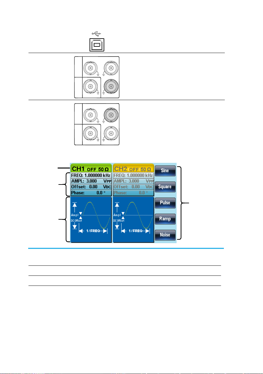
1-2. Panel Overview
Front Panel
/
LCD
Display
Function keys,
Return key
Scroll
Wheel
Output
Terminals
Number pad
Power
switch
Output key
Channel
select key
Arrow keys
Operation keys
LCD Display
TFT color display, 320 x 240 resolution.
Function Keys
F1~F5
F1
Activates functions which appear on the
right-hand side of the LCD display.
Return Key
Return
Goes back to the previous menu level.
Operation Keys
Waveform
The waveform key is used to select a
type of waveform.
FREQ/Rate
The FREQ/Rate key is used to set the
frequency or sample rate.
AMP
AMPL sets the waveform amplitude.
DC Offset
Sets the DC offset.
UTIL
The UTIL key is used to access the
save and recall options, update and
view the firmware version, access the
calibration options, output impedance
settings and frequency meter.
ARB
ARB is used to set the arbitrary
waveform parameters.
3
MOD
Sweep
Burst
The MOD, Sweep and Burst keys are
used to set the modulation, sweep and
burst settings and parameters.
Preset Key
Preset
The preset key is used to recall a preset
state.
Output Key
OUTPUT
The Output key is used to turn on or off
the waveform output.
Channel Select
Key
CH1/CH2
The channel select key is used to
switch between the two output
channels.
Output ports
OUTPUT
50Ω
50Ω
CH2
CH1
CH1: Channel 1 output port
CH2: Channel 2 output port
Power Button
Turns the power on or off.
Arrow Keys
Used to select digits when editing
parameters.
Scroll Wheel
The scroll wheel is used to edit values
and parameters.
Decrease Increase
Keypad
0
/
321
4
7 859
6
The digital keypad is used to enter
values and parameters. The keypad is
often used in conjunction with the arrow
keys and variable knob.
4
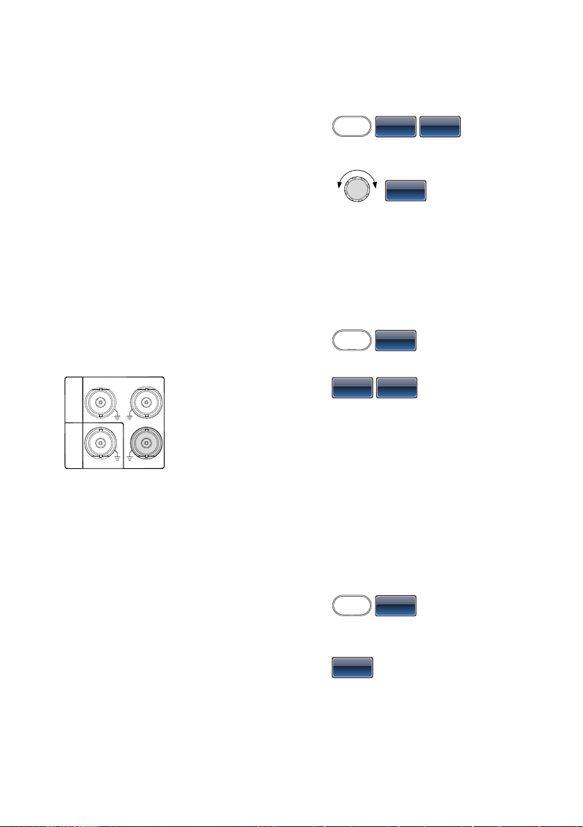
Rear Panel
USB Host port Trigger output
Input Terminals
USB Device port
FanPower socket input
Trigger Input
IN
OUT
Trigger
Counter
Trigger
MOD
External trigger input. Used to receive
external trigger signals.
Trigger Output
IN
OUT
Trigger
Counter
Trigger
MOD
Marker output signal. Used for Sweep
and ARB mode only.
Fan Fan.
Power Input
Socket
AC 100-240V
50-60Hz 25W MAX
Power input: 100~240V AC
50~60Hz.
USB Host
Host
USB type-A host port.
5
USB Device Port
Device
USB type-B device port is used to
connect the function generator to a PC
for remote control.
Counter Input
IN
OUT
Trigger
Counter
Trigger
MOD
Frequency counter input.
MOD Input
IN
OUT
Trigger
Counter
Trigger
MOD
Modulation input terminal.
Display
Soft Menu
Keys
Status Tabs
Parameter
Windows
Waveform
Display
Parameter
Windows
The Parameter display and edit window.
Status Tabs
Displays the current channel and setting status.
Waveform Display
Used to display the waveform
Soft Menu Keys
The function keys (F1~F5) beside the Soft Menu keys
correspond to the soft keys.
6
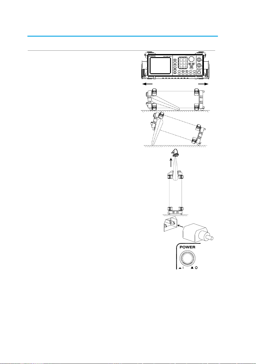
1-3. Setting Up the function Generator
Background
This section describes how to adjust the handle and
power up the function generator.
Adjusting the
Handle
Pull out the handle
sideways and rotate it.
/
AF G-2 2 25
Place the FGX-2220
horizontally,
Or tilt the stand.
Place the handle
vertically to hand carry.
Power Up
1. Connect the power cord to the
socket on the rear panel.
2. Turn on the power switch on the
front panel.
3. When the power switch is turned on the screen
displays the loading screen.
The function generator is now ready to be used.
7
2. QUICK REFERENCE
This chapter describes the operation shortcuts, built-in help and factory default
settings. This chapter is to be used as a quick reference, for detailed explanations
on parameters, settings and limitations, please see the operation chapters
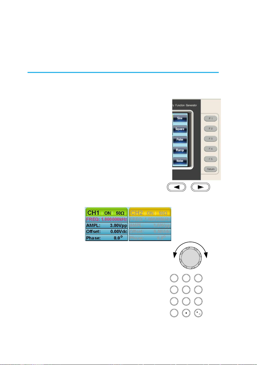
2-1. How to use the Digital Inputs
Background
The FGX-2220 has three main types of digital inputs:
the number pad, arrow keys and scroll wheel. The
following instructions will show you how to use the
digital inputs to edit parameters.
1. To select a menu item, press
the corresponding function
keys below (F1~F5). For
example the function key F1
corresponds to the Soft key
“Sine”.
2. To edit a digital value, use
the arrow keys to move the
cursor to the digit that
needs to be edited.
3. Use the scroll wheel to edit
the parameter. Clockwise
increases the value, counter
clockwise decreases the
value.
4. Alternatively, the number pad
can be used to set the value of
a highlighted parameter.
0
/
321
4
7 859
6
8
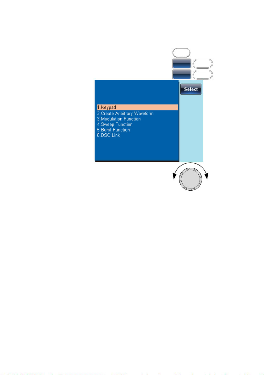
2-2. How to use the Help Menu
Background
Every key and function has a detailed description in the
help menu.
1. Press UTIL
UTIL
2. Press System (F3)
System
F3
3. Press Help (F2)
Help
F2
4. Use the scroll wheel to navigate
to a help item. Press Select to
choose the item.
Keypad
Provides help on any front panel
key that is pressed.
Create Arbitrary
Waveform
Provides help on creating arbitrary
waveforms.
Modulation
Function
Explains how to create Modulated
waveforms.
Sweep Function
Provides help on the Sweep
function.
Burst Function
Provides help on the Burst
function.
DSO Link
Provides help on DSO link.
5. For example, select item 4 to see help on the sweep
functions.
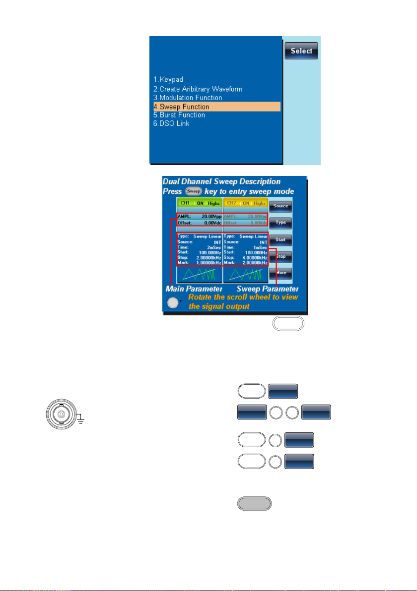
9
6. Use the scroll wheel to navigate the help information.
7. Press Return to return to the
previous menu.
Return
2-3. Selecting a Waveform
2-3-1. Square Wave
Example: Square wave, 3Vpp, 75% duty cycle, 1kHz.
Output:
50Ω
CH1
1. Press Waveform and
select Square (F2).
Waveform
Square
2. Press Duty (F1), 7 + 5 +
%(F2).
Duty
7
5
%
Input: N/A
3. Press Freq/Rate, 1 +
kHz (F4).
FREQ/Rate
1
kHz
4. Press AMPL followed
by, 3 + VPP (F5).
AMPL
3
VPP
5. Press the Output key.
OUTPUT
10
2-3-2. Ramp Wave
Example: Ramp Wave, 5Vpp, 10kHz, 50% Symmetry.
Output:
50Ω
CH1
1. Press the Waveform
key, and select Ramp
(F4).
Waveform
Ramp
2. Press SYM(F1), 5 + 0
+%(F2).
SYM
5
0
%
Input: N/A
3. Press the Freq/Rate key
then 1 + 0 + kHz (F4).
FREQ/Rate
1
0
kHz
4. Press the AMPL key
then 5 +VPP (F5).
AMPL
5
VPP
5. Press the Output key.
OUTPUT
2-3-3. Sine Wave
Example: Sine Wave, 10Vpp,100kHz
Output:
50Ω
CH1
Input: N/A
1. Press the Waveform key
and select Sine (F1).
Waveform
Sine
2. Press the Freq/Rate key,
followed by 1 + 0 +0 +
kHz (F4).
FREQ/Rate
100
kHz
3. Press the AMPL key,
followed by 1 + 0 +VPP
(F5).
AMPL
1
0
VPP
4. Press the output key.
OUTPUT
2-4. Modulation
2-4-1. AM
Example: AM modulation. 100Hz modulating square wave. 1kHz Sine wave
carrier. 80% modulation depth.
Output:
50Ω
CH1
1. Press the MOD key and
select AM (F1).
MOD
AM
2. Press Waveform and
select Sine (F1).
Waveform
Sine
Input: N/A
3. Press the Freq/Rate
key, followed by 1 + kHz
(F4).
FREQ/Rate
1
kHz
4. Press the MOD key,
select AM (F1), Shape
(F4), Square (F2).
MOD
AM
Shape
Square
5. Press the MOD key,
select AM (F1), AM Freq
(F3).
MOD
AM
AM Freq
6. Press 1 + 0 + 0 + Hz
(F2).
100
Hz
11
7. Press the MOD key,
select AM (F1), Depth
(F2).
MOD
AM
Depth
8. Press 8 + 0 + % (F1).
8
0
%
9. Press MOD, AM (F1),
Source (F1), INT (F1).
MOD
AM
Source
INT
10. Press the output key.
OUTPUT
2-4-2. FM
Example: FM modulation. 100Hz modulating square wave. 1kHz Sine wave
carrier. 100 Hz frequency deviation. Internal Source.
Output:
50Ω
CH1
1. Press the MOD key and
select FM (F2).
MOD
FM
2. Press Waveform and
select Sine (F1).
Waveform
Sine
Input: N/A
3. Press the Freq/Rate
key, followed by 1 + kHz
(F4).
FREQ/Rate
1
kHz
4. Press the MOD key,
select FM (F2), Shape
(F4), Square (F2).
MOD
FM
Shape
Square
5. Press the MOD key,
select FM (F2), FM Freq
(F3).
MOD
FM
FM Freq
6. Press 1 + 0 + 0 + Hz
(F2).
100
Hz
7. Press the MOD key,
select FM (F2), Freq
Dev (F2).
MOD
FM
Freq Dev
8. Press 1 + 0 + 0 + Hz
(F3).
100
Hz
9. Press MOD, FM (F2),
Source (F1), INT (F1).
MOD
FM
Source
INT
10. Press the Output key.
OUTPUT
2-4-3. FSK Modulation
Example: FSK modulation. 100Hz Hop frequency. 1kHz Carrier wave. Sine
wave. 10 Hz Rate. Internal Source.
Output:
50Ω
CH1
1. Press the MOD key and
select FSK (F3).
MOD
FSK
2. Press Waveform and
select Sine (F1).
Waveform
Sine
12
Input: N/A
3. Press the Freq/Rate
key, followed by 1 + kHz
(F4).
FREQ/Rate
1
kHz
4. Press the MOD key,
select FSK (F3), FSK
Rate (F3).
MOD
FSK
FSK Rate
5. Press 1 + 0 + Hz (F2).
1
0
Hz
6. Press the MOD key,
select FSK (F3), Hop
Freq (F2).
MOD
FSK
Hop Freq
7. Press 1 + 0 + 0 + Hz
(F3).
100
Hz
8. Press MOD, FSK (F3),
Source (F1), INT (F1).
MOD
FSK
Source
INT
9. Press the output key.
OUTPUT
2-4-4. PM Modulation
Example: PM modulation. 800Hz sinusoidal carrier wave. 15 kHz modulating
sine wave. 50˚ phase deviation. Internal Source.
Output:
50Ω
CH1
1. Press Waveform and
select Sine (F1).
Waveform
Sine
2. Press the MOD key and
select PM (F4).
MOD
PM
Input: N/A
3. Press the Freq/Rate
key, followed by 8 + 0 +
0 + Hz (F3).
FREQ/Rate
800
Hz
4. Press the MOD key,
select PM (F4), Shape
(F4), Sine (F1).
MOD
PM
Shape
Sine
5. Press MOD, then PM
(F4), PM Freq (F3).
MOD
PM
PM Freq
6. Press 1 + 5 + kHz (F3).
1
5
kHz
7. Press MOD, PM (F4),
PM Dev (F2).
MOD
PM
PM Dev
8. Press 5 + 0 + Degree
(F1).
5
0
Degree
9. Press MOD, PM (F4),
Source (F1), INT (F1).
MOD
PM
Source
INT
10. Press the Output key.
OUTPUT
13
2-4-5. SUM Modulation
Example: SUM modulation. 100Hz modulating square wave, 1kHz sinusoidal
carrier wave, 50% SUM amplitude, internal source.
Output:
50Ω
CH1
1. Press the MOD key,
then SUM (F5).
MOD
SUM
2. Press Waveform, and
select Sine (F1).
Waveform
Sine
Input: N/A
3. Press Freq/Rate
followed by 1 + kHz
(F4).
FREQ/Rate
1
kHz
4. Press the MOD key,
SUM (F5), Shape (F4),
Square (F2).
MOD
SUM
Shape
Square
5. Press the MOD key and
select SUM (F5), SUM
Freq (F3).
MOD
SUM
SUM Freq
6. Press 1 + 0 + 0 + Hz
(F2).
100
Hz
7. Press the MOD key and
select SUM (F5), SUM
Ampl (F2).
MOD
SUM
SUM Ampl
8. Press 5 + 0 + % (F1).
5
0
%
9. Press MOD, SUM (F5),
Source (F1), INT (F1).
MOD
SUM
Source
INT
10. Press the Output key.
OUTPUT
2-5. Sweep
Example: Frequency Sweep. Start Frequency 10mHz, Stop frequency 1MHz.
Log sweep, 1 second sweep, Marker Frequency 550 Hz, Manual Trigger.
Output:
50Ω
CH1
1. Press Sweep, Start (F3).
MOD
START
2. Press 1 + 0 + mHz (F2).
1
0
mHz
3. Press Sweep, Stop (F4).
Sweep
Stop
Input: N/A
4. Press 1 + MHz (F5).
1
MHz
5. Press Sweep, Type
(F2), Log (F2).
Sweep
Type
Log
6. Press Sweep, More
(F5), SWP Time (F1).
Sweep
More
SWP Time
7. Press 1 + SEC (F2).
1
SEC
14
8. Press Sweep, More
(F5), Marker (F4),
ON/OFF (F2), Freq (F1).
Sweep
More
Marker
ON/OFF
Freq
9. Press 5 + 5 + 0 + Hz
(F3).
550
Hz
10. Press the Output key.
OUTPUT
11. Press Sweep, Source
(F1), Manual (F3),
Trigger (F1).
Sweep
Source
Manual
Trigger
2-6. Burst
Example: Burst Mode, N-Cycle (Internally triggered), 1kHz burst frequency,
Burst count = 5, 10 ms Burst period, 0˚ burst phase, Internal trigger, 10 us
delay, rising edge trigger out
Output:
50Ω
CH1
1. Press FREQ/Rate 1 kHz
(F4).
FREQ/Rate
1
kHz
2. Press Burst, N Cycle
(F1), Cycles (F1).
Burst
N Cycle
Cycles
Input: N/A
3. Press 5 + Cyc (F2).
5
Cyc
4. Press Burst, N Cycle
(F1), Period (F4).
Burst
N Cycle
Period
5. Press 1 +0 + msec (F2).
1
0
mSEC
6. Press Burst, N Cycle
(F1), Phase (F3).
Burst
N Cycle
Phase
7. Press 0 + Degree (F2).
0
Degree
8. Press Burst, N Cycle
(F1), TRIG set (F5), INT
(F1).
Burst
N Cycle
TRIG set
INT
9. Press Burst, N Cycle
(F1), TRIG set (F5),
Delay (F4).
Burst
N Cycle
TRIG set
Delay
10. Press 1 + 0 + uSEC
(F2).
1
0
uSEC
11. Press Burst, N Cycle
(F1), TRIG set (F5),
TRIG out (F5), ON/OFF
(F3), Rise (F1).
Burst
N Cycle
TRIG set
TRIG out
ON/OFF
Rise
12. Press the Output key.
OUTPUT
15
2-7. ARB
2-7-1. ARB–Add Built-In Waveform
Example: ARB Mode, Exponential Rise. Start 0, Length 100, Scale 327.
Output:
50Ω
CH1
1. Press ARB, Built in (F3),
Wave (F4), Math(F2),
use the scroll wheel to
select Exporise and
then press Select(F5).
ARB
Built in
Wave
Math
Select
2. Press Start (F1), 0 +
Enter (F2), Return.
Start0Enter
Return
3. Press Length (F2), 100,
Enter (F2), Return.
Length
100
Enter
Return
4. Press Scale (F3), 327,
Enter (F2), Return,
Done (F5).
Scale
327
Enter
Return
Done
2-7-2. ARB- Add Point
Example: ARB Mode, Add point, Address 40, data 300.
Output:
50Ω
CH1
1. Press ARB, Edit (F2),
Point (F1), Address (F1)
ARB
Edit
Point
Adress
2. Press 4 + 0 + Enter (F2),
Return
4
0
Enter
Return
3. Press Data (F2), 3+0+0,
Enter (F2).
Data
300
Enter
2-7-3. ARB- Add Line
Example: ARB Mode, Add line, Address:Data (10:30, 50:100)
Output:
50Ω
CH1
1. Press ARB, Edit (F2),
Line (F2), Start ADD
(F1).
ARB
Edit
Line
Start ADD
2. Press 1 + 0 + Enter (F2),
Return.
1
0
Enter
Return
16
3. Press Start Data (F2), 3
+ 0, Enter (F2), Return.
Start Data
3
0
Enter
Return
4. Press Stop ADD (F3), 5
+ 0, Enter (F2), Return.
Stop ADD
5
0
Enter
Return
5. Press Stop Data (F4), 1
+ 0 + 0, Enter (F2),
Return, Done (F5).
Stop Data
100
Enter
Return
Done
2-7-4. ARB– Output Section
Example: ARB Mode, Output ARB Waveform, Start 0, Length 1000.
Output:
50Ω
CH1
1. Press ARB, Output (F4).
ARB
Output
2. Press Start (F1), 0 +
Enter (F2), Return.
Start0Enter
Return
3. Press Length (F2), 1 + 0
+ 0, Enter (F2), Return.
Length
100
Enter
Return
2-8. Utility Menu
2-8-1. Save
Example: Save to Memory file #5.
1. Press UTIL, Memory
(F1), Store (F1).
UTIL
Memory
Store
2. Choose a setting using
the scroll wheel and
press Done (F5).
Done
17
2-8-2. Recall
Example: Recall Memory file #5.
1. Press UTIL, Memory
(F1), Recall (F2).
UTIL
Memory
Recall
2. Choose a setting using
the scroll wheel and
press Done (F5).
Done
2-9. Frequency Counter
2-9-1. Frequency Counter
Example: Turn on the frequency counter. Gate time: 1 second.
Output: N/A
Input:
IN
OUT
Trigger
Counter
Trigger
MOD
1. Press UTIL, Counter
(F5).
UTIL
Counter
2. Press Gate Time (F1),
and press 1 Sec (F3) to
choose a gate time of 1
second.
Gate Time
1 Sec
3. Connect the signal of interest to the Frequency
counter input on the rear panel.
2-10. Coupling
2-10-1. Frequency Coupling
Example: Frequency Coupling
1. Press UTIL, Dual Chan
(F4) to enter the
coupling function.
UTIL
Dual Chan
2. Press Freq Cpl (F1) to
select the frequency
coupling function.
Freq Cpl

18
3. Press Offset (F2). The
offset is the frequency
difference between CH1
and CH2. Use the
number keys or scroll
wheel to enter the offset.
Offset
2-10-2. Amplitude Coupling
Example: Amplitude Coupling
1. Press UTIL, Dual Chan
(F4) to enter the
coupling function.
UTIL
Dual Chan
2. Press Ampl Cpl (F2),
ON (F1) to select the
amplitude coupling
function.
Ampl Cpl
On
3. Couples the amplitude and offset between both
channels. Any changes in amplitude in the current
channel are reflected in the other channel.
2-11. Tracking
Example: Tracking
1. Press UTIL, Dual Chan
(F4) to enter the
coupling function.
UTIL
Dual Chan
2. Press Tracking (F3), ON
(F2) to turn on the
tracking function.
Tracking
On
3. When tracking is turned on, parameters such as
amplitude and frequency from the current channel are
mirrored on the other channel.

19
2-12. Menu Tree
Conventions
Use the menu trees as a handy reference for the function
generator functions and properties. The FGX-2220 menu
system is arranged in a hierarchical tree. Each
hierarchical level can be navigated with the operation or
soft menu keys. Pressing the Return key will return you
to the previous menu level.
2-12-1. Waveform
Duty
%
Waveform
Width
nSEC
uSEC
mSEC
SEC
SYM
%
Sine Square Pulse Ramp Noise
2-12-2. ARB-Display
Horizon Vertical Next Page Back Page Overview
Display
ARB
Clear
Enter
Start
Clear
Enter
Length
Clear
Enter
Center
Zoom in
Zoom out
Clear
Enter
Low
Clear
Enter
High
Clear
Enter
Center
Zoom in
Zoom out

20
2-12-3. ARB-Edit
Point Line Copy Clear Protect
Edit
ARB
Clear
Enter
Address
Data
Start ADD
Start Data
Stop ADD
Stop Data
Start
Length
Paste To
Start
Length
Done
All
All
Done
Start
Length
Done
Unprotect
Done
Clear
Enter
Clear
Enter
Clear
Enter
Clear
Enter
Clear
Enter
Clear
Enter
Clear
Enter
Clear
Enter
Clear
Enter
Clear
Enter
Clear
Enter
Clear
Enter
Done
Done
Done
2-12-4. ARB- Built In
Built in
ARB
Start Length Scale Wave Done
Clear
Enter
Clear
Enter
Clear
Enter
Common
Math
Window
Engineer
Select

21
2-12-5. ARB-Save
Start Length Memory USB
Save
ARB
Select
Enter Char
Back Space
Save
New Folder
Enter Char
Back Space
Save
New File
More
Clear
Enter
Clear
Enter
Select
Done
2-12-6. ARB-Load
Memory USB To Done
Load
ARB
More
SelectSelect
Clear
Enter

22
2-12-7. ARB-Output
Output
ARB
Start Length
Clear
Enter
Clear
Enter
2-12-8. MOD
AM FM FSK PM
MOD
Int
EXT
Source
%
Depth
Int
EXT
Source
uHz
mHz
Hz
kHz
MHz
Freq Dev
mHz
Hz
kHz
AM Freq
Sine
Square
Triangle
UpRamp
DnRamp
Shape
mHz
Hz
kHz
FM Freq
Sine
Square
Triangle
UpRamp
DnRamp
Shape
Int
EXT
Source
uHz
mHz
Hz
kHz
MHz
Hop Freq
mHz
Hz
kHz
MHz
FSK Rate
Int
EXT
Source
Degree
Phase Dev
mHz
Hz
kHz
PM Freq
Sine
Square
Triangle
UpRamp
DnRamp
Shape
SUM
Int
EXT
Source
%
SUM Ampl
mHz
Hz
kHz
SUM Freq
Sine
Square
Triangle
UpRamp
DnRamp
Shape

23
2-12-9. SWEEP
Linear
Log
Source Type Start Stop More
SWEEP
Int
EXT
uHz
mHz
Hz
kHz
MHz
uHz
mHz
Hz
kHz
MHz
Go to the
Sweep -
More menu
Manual
Trigger
2-12-10. SWEEP- More
Span Center Marker
Freq
uHz
mHz
Hz
kHz
MHz
uHz
mHz
Hz
kHz
MHz
uHz
mHz
Hz
kHz
MHz
ON/OFF
SWP Time
mSEC
SEC
More
Sweep

24
2-12-11. Burst- N Cycle
Cycles Infinite Phase Period
Clear
Cyc
N Cycle
Burst
TRIG Setup
Clear
Degree
uSEC
mSEC
SEC
Int
Rise
Fall
EXT
Trigger
Manual
nSEC
uSEC
mSEC
SEC
Delay
Rise
Fall
ON/OFF
TRIG out
2-12-12. Burst – Gate
Polarity Phase
Pos
Neg
Gate
Burst
Clear
Degree

25
2-12-13. UTIL
Memory Cal. System Dual Chan
UTIL
Store
Recall
Delete
Self Test
Version
Upgrade
Software
Language
Select
Beep
Delete All
Done
Help
Off
Offset
Ratio
Freq Cpl
0.01 Sec
0.1 Sec
1 Sec
10 Sec
Gate Time
Counter
Off
On
Ampl Cpl
Off
On
Inverted
Tracking
Done
Done
Done
English
S_Phase
2-12-14. CH1/CH2
Load Phase
50 OHM
High Z
Phase
Degree
DSO Link
CH1
CH2
CH3
CH4
Search
CH1/ CH2
2-13. Default Settings
The Preset key is used to restore the default panel
settings.
Preset
Output Settings
Function
Sine Wave
Frequency
1kHz
Amplitude
3.000 Vpp
Offset
0.00V dc
Output units
Vpp Output terminal
50Ω

26
Modulation
Carrier wave
1kHz sine wave
Modulation wave
100Hz sine wave
AM depth
100%
FM deviation
100Hz
FSK hop frequency
100Hz
FSK frequency
10Hz
PM phase deviation
180˚
SUM amplitude
50%
Modem status
Off
Sweep
Start/Stop frequency
100Hz/1kHz
Sweep time
1s Sweep type
Linear
Sweep status
Off
Burst
Burst frequency
1kHz
Ncycle
1 Burst period
10ms
Burst starting phase
0˚
Burst status
Off
System Settings
Power off signal
On Display mode
On Error queue
Cleared
Memory settings
No change
Output
Off
Trigger
Trigger source
Internal (immediate)
Calibration
Calibration Menu
Restricted

27
3. OPERATION
The Operation chapter shows how to output basic waveform functions. For details
on modulation, sweep, burst and arbitrary waveforms, please see the Modulation
and Arbitrary waveform chapters on pages 35 and 98.
3-1. Select a Waveform
The FGX-2220 can output 5 standard waveforms: sine, square, pulse, ramp and
noise.
3-1-1. Sine Wave
Panel Operation
1. Press the Waveformkey.
Waveform
2. Press F1 (Sine).
Sine
F1
3-1-2. Square Wave
Panel Operation
1. Press the Waveform key.
Waveform
2. Press F2 (Square) to create a
square waveform.
Square
F2
3. Press F1 (Duty). The Duty
parameter will be highlighted in
the parameter window.
Duty
F1

28
4. Use the arrow keys and scroll
wheel or number pad to enter the
Duty range.
0
/
321
4
7 859
6
5. Press F2 (%) to select % units.
%
F2
Range
Frequency
Duty Range
≤100kHz
1.0%~99.0%
100kHz~≤1MHz
10.0%~90.0%
>1MHz~25MHz
50% (Fixed)
3-1-3. Setting the Pulse Width
Panel Operation
1. Press the Waveform key.
Waveform
2. Press F3 (Pulse) to create a
pulse width waveform.
Pulse
F3

29
3. Press F1 (Width). The Width
parameter will be highlighted in
the parameter window.
Width
F1
4. Use the arrow keys and scroll
wheel or number pad to enter the
pulse width.
0
/
321
4
7 859
6
5. Press F2~F5 choose the unit
range.
nSEC
F2
~
SEC
F5
Range
Pulse Width
20ns~1999.9s
Note
Minimum Pulse Width
Frequency ≤ 25MHz:
20ns pulse width.
Frequency ≤ 100 kHZ:
1/4096 duty cycle.
Resolution
Frequency ≤ 25MHz:
20ns pulse width.
Frequency ≤100 kHZ:
1/4096 duty cycle.

30
Note
Rise time / Fall time approx.. 17ns(typ.)
Note
Setting of the pulse width can be set up to 20ns, but it
is less than 100ns, not a square wave by the
specifications.
3-1-4. Setting a Ramp Waveform
Panel Operation
1. Press the Waveform key.
Waveform
2. Press F4 (Ramp) to create a
ramp waveform.
Ramp
F4
3. Press F1 (SYM). The SYM
parameter will be highlighted in
the parameter window.
SYM
F1
4. Use the arrow keys and scroll
wheel or number pad to enter the
symmetry percentage.
0
/
321
4
7 859
6
5. Press F2 (%) to choose % units.
%
F2
Range
Symmetry
0%~100%

31
3-1-5. Selecting a Noise Waveform
Panel Operation
1. Press the Waveform key.
Waveform
2. Press F5 (Noise).
Noise
F5

32
3-1-6.Setting the Frequency
Panel Operation
1. Press the FREQ/Rate key.
FREQ/Rate
2. The FREQ parameter will become highlighted in the
parameter window.
3. Use the arrow keys and scroll
wheel or number pad to enter the
frequency.
0
/
321
4
7 859
6
4. Choose a frequency unit by
pressing F1~F5.
uHz
F1
~
MHz
F5
Range
Sine wave
1μHz~25MHz
Square wave
1μHz~25MHz
Pulse wave
500μHz~25MHz
Ramp wave
1μHz~1MHz

33
3-1-7. Setting the Amplitude
Panel Operation
1. Press the AMPL key.
AMPL
2. The AMPL parameter will become highlighted in the
parameter window.
3. Use the arrow keys and scroll
wheel or number pad to enter the
amplitude.
0
/
321
4
7 859
6
4. Choose a unit type by pressing
F1~F5.
dBm
F1
~
VPP
F5
50Ω load
High Z
Range
1mVpp~10Vpp
2mVpp~20Vpp
Unit
Vpp, Vrms, dBm

34
3-1-8. Setting the DC Offset
Panel Operation
1. Press the DC Offset key.
DC Offset
2. The DC Offset parameter will become highlighted in
the parameter window.
3. Use the arrow keys and scroll
wheel or number pad to enter the
DC Offset.
0
/
321
4
7 859
6
4. Press F1 (mVDC) or F2 (VDC) to
choose a voltage range.
mVDC
F1
VDC
F2
50Ω load
High Z
Range
±5Vpk
±10Vpk

35
4. MODULATION
The FGX-2220 Series Arbitrary Function Generators are able to produce AM, FM,
FSK, PM and SUM modulated waveforms. Depending on the type of waveform
produced, different modulation parameters can be set. Only one modulation
mode can be active at any one time. The function generator also will not allow
sweep or burst mode to be used with AM/FM. Activating a modulation mode will
turn the previous modulation mode off.
4-1. Amplitude Modulation (AM)
An AM waveform is produced from a carrier waveform and a modulating waveform.
The amplitude of the modulated carrier waveform depends on the amplitude of the
modulating waveform. The FGX-2220 function generator can set the carrier
frequency, amplitude and offset as well as internal or external modulation sources.

36
4-1-1. Selecting AM Modulation
Panel Operation
1. Press the MOD key.
MOD
2. Press F1 (AM).
AM
F1
4-1-2. AM Carrier Shape
Background
Sine, square, ramp, pulse or arbitrary waveforms can be
used as the carrier shape. The default waveform shape
is set to sine. Noise is not available as a carrier shape.
Before the carrier shape can be selected, choose AM
modulation mode, see above.
Select a Standard
Carrier Shape
1. Press the Waveform key.
Waveform
2. Press F1~F4 to choose the
carrier wave shape.
Sine
F1
~
Ramp
F4
Select an Arbitrary
Waveform Carrier
Shape.
3. See the Arbitrary waveform quick
reference or chapter to use an
arbitrary waveform.
Page 15
Page 98
Range
AM Carrier Shape
sine, square, Ramp,Pulse, arbitrary
waveform

37
4-1-3. Carrier Frequency
The maximum carrier frequency depends on the carrier shape selected. The
default carrier frequency for all carrier shapes is 1kHz.
Panel Operation
1. With a carrier waveform
selected, press the FREQ/Rate
key.
FREQ/Rate
2. The FREQ parameter will become highlighted in the
parameter window.
3. Use the arrow keys and scroll
wheel or number pad to enter the
carrier frequency.
0
/
321
4
7 859
6
4. Press F1~F5 to select the
frequency range.
uHz
F1
~
MHz
F5
Range
Carrier Shape
Carrier Frequency
Sine wave
1μHz~ 25MHz
Square wave
1μHz~25MHz
Ramp wave
1μHz~1MHz
Pulse wave
500uHz~25MHz
Default frequency
1 kHz

38
4-1-4. Modulating Wave Shape
The function generator can accept internal as well as external sources. The
FGX-2220 has sine, square, triangle, up ramp and down ramp modulating
waveform shapes. Sine waves are the default wave shape.
Panel Operation
1. Press the MOD key.
MOD
2. Press F1 (AM).
AM
F1
3. Press F4 (Shape).
Shape
F4
4. Press F1 ~ F5 to select the
waveform shape.
Sine
F1
~
DnRamp
F5
5. Press Return to return to the
previous menu.
Return
Note
Square wave
50% Duty cycle
UpRamp
100% Symmetry
Triangle
50% Symmetry
DnRamp
0% Symmetry

39
4-1-5. AM Frequency
The frequency of the modulation waveform (AM Frequency) can be set from 2mHz
to 20kHz.
Panel Operation
1. Press the MOD key.
MOD
2. Press F1 (AM).
AM
F1
3. Press F3 (AM Freq)
AM Freq
F3
4. The AM Freq parameter will become highlighted in
the Waveform display area.
5. Use the arrow keys and scroll
wheel or number pad to enter the
AM frequency.
0
/
321
4
7 859
6
6. Press F1~F3 to select the
frequency range.
mHz
F1
~
kHz
F3
Range
Modulation frequency
2mHz~20kHz
Default frequency
100Hz

40
4-1-6. Modulation Depth
Modulation depth is the ratio (as a percentage) of the unmodulated carrier
amplitude and the minimum amplitude deviation of the modulated waveform. In
other words, modulation depth is the maximum amplitude of the modulated
waveform compared to the carrier waveform as a percentage.
Panel Operation
1. Press the MOD key.
MOD
2. Press F1 (AM).
AM
F1
3. Press F2 (Depth).
Depth
F2
4. The AM Depth parameter will become highlighted in
the waveform display area.
5. Use the arrow keys and scroll
wheel or number pad to enter the
AM depth.
0
/
321
4
7 859
6
6. Press F1 (%) to choose % units.
%
F1
Range
Depth
0%~120%
Default depth
100%

41
Note
When the modulation depth is greater than 100%, the
output cannot exceed ±5VPeak (10kΩ load).
If an external modulation source is selected, modulation
depth is limited to ± 5V from the MOD INPUT terminal on
the rear panel. For example, if the modulation depth is
set to 100%, then the maximum amplitude is +5V, and
the minimum amplitude is -5V.
4-1-7. Selecting the (AM) Modulation Source
The function generator will accept an internal or external source for AM modulation.
The default source is internal.
Panel Operation
1. Press the MOD key.
MOD
2. Press F1 (AM).
AM
F1
3. Press F1 (Source).
Source
F1
4. Press F1 (INT) or F2 (EXT) to
select the modulation source.
INT
F1
~
EXT
F2
5. Press Return to go back to the
previous menu.
Return
External Source
Use the MOD INPUT terminal on the
rear panel when using an external
source.
IN
OUT
Trigger
Counter
Trigger
MOD
Note
If an external modulation source is selected, modulation
depth is limited to ± 5V from the MOD INPUT terminal on
the rear panel. For example, if modulation depth is set to
100%, then the maximum amplitude is +5V, and the
minimum amplitude is -5V.

42
4-2. Frequency Modulation (FM)
A FM waveform is produced from a carrier waveform and a modulating waveform.
The instantaneous frequency of the carrier waveform varies with the magnitude of
the modulating waveform. When using the FGX-2220 function generator, only one
type of modulated waveform can be created at any one time.

43
4-2-1. Selecting Frequency Modulation (FM)
When FM is selected, the modulated waveform depends on the carrier frequency,
the output amplitude and offset voltage.
Panel Operation
1. Press the MOD key.
MOD
2. Press F2 (FM).
FM
F2
4-2-2. FMCarrier Shape
Background
The default waveform shape is set to sine. Noise and
pulse waveforms cannot be used as a carrier wave.
Panel Operation
1. Press the Waveform key.
Waveform
2. Press F1~F4 to select the carrier
shape.
Sine
F1
~
Ramp
F4
Range
Carrier Shape
Sine, Square, Ramp.
4-2-3. FM Carrier Frequency
When using the FGX-2220 function generator, the carrier frequency must be equal
to or greater than the frequency deviation. If the frequency deviation is set to value
greater than the carrier frequency, the deviation is set to the maximum allowed.
The maximum frequency of the carrier wave depends on the waveform shape
chosen.

44
Panel Operation
1. To select the carrier frequency,
press the FREQ/Rate key.
FREQ/Rate
2. The FREQ parameter will become highlighted in the
parameter window.
3. Use the arrow keys and scroll
wheel or number pad to enter the
carrier frequency.
0
/
321
4
7 859
6
4. Press F1~F5 to select the
frequency unit.
uHz
F1
~
MHz
F5
Range
Carrier Shape
Carrier Frequency
Sine
1μHz~25MH
Square
1μHz~15MHz
Ramp
1μHz~1MHz
Default frequency
1kHz

45
4-2-4. FM Wave Shape
The function generator can accept internal as well as external sources. The
FGX-2220 has sine, square, triangle, positive and negative ramps (UpRamp,
DnRamp) as the internal modulating waveform shapes. Sine is the default wave
shape.
Background
1. Select MOD.
MOD
2. Press F2 (FM).
FM
F2
3. Press F4 (Shape).
Shape
F4
4. Press F1 ~ F5 to select the
waveform shape.
Sine
F1
~
DnRamp
F5
5. Press Return to return to the
previous menu.
Return
Range
Square wave
50% Duty cycle
UpRamp
100% Symmetry
Triangle
50% Symmetry
DnRamp
0% Symmetry

46
4-2-5. FM Frequency
The frequency of the modulation waveform (FM Frequency) can be set from 2mHz
to 20kHz.
Panel Operation
1. Press the MOD key.
MOD
2. Press F2 (FM).
FM
F2
3. Press F3 (FM Freq).
FM Freq
F3
4. The FM Freq parameter will become highlighted in
waveform display panel.
5. Use the arrow keys and scroll
wheel or number pad to enter the
FM frequency.
0
/
321
4
7 859
6
6. Press F1~F3 to select the
frequency unit.
mHz
F1
~
kHz
F3
Range
Modulation frequency
2mHz~20kHz
Default frequency
100Hz

47
4-2-6. Frequency Deviation
The frequency deviation is the peak frequency deviation from the carrier wave and
the modulated wave.
Panel Operation
1. Press the MOD key.
MOD
2. Press F2 (FM).
FM
F2
3. Press F2 (Freq Dev).
Freq Dev
F2
4. The Freq Dev parameter will become highlighted in
the waveform display panel.
5. Use the arrow keys and scroll
wheel or number pad to enter the
frequency deviation.
0
/
321
4
7 859
6
6. Press F1~ F5 to choose the
frequency units.
uHz
F1
~
MHz
F5
Range
Frequency Deviation
DC~25MHz
DC~15MHz(square)
DC~1MHz (Ramp)
Default depth
100Hz

48
4-2-7. Selecting (FM) Modulation Source
The function generator will accept an internal or external source for FM modulation.
The default source is internal.
Panel Operation
1. Press the MOD key.
MOD
2. Press F2 (FM).
FM
F2
3. Press F1 (Source).
Source
F1
4. To select the source, press F1
(Internal) or F2 (External).
INT
F1
~
EXT
F2
5. Press Return to return to the
previous menu.
Return
External Source
Use the MOD INPUT terminal on the
rear panel when using an external
source.
IN
OUT
Trigger
Counter
Trigger
MOD
Note
If an external modulating source is selected, the
frequency deviation is limited to the ± 5V MOD INPUT
terminal on the rear panel. The frequency deviation is
proportional to the signal level of the modulation in
voltage. For example, if the modulation in voltage is +5V,
then the frequency deviation would be equal to the set
frequency deviation. Lower signal levels reduce the
frequency deviation while negative voltage levels
produce frequency deviations with frequencies below the
carrier waveform.

49
4-3. Frequency Shift Keying (FSK) Modulation
Frequency Shift Keying Modulation is used to shift the frequency output of the
function generator between two preset frequencies (carrier frequency, hop
frequency). The frequency at which the carrier and hop frequency shift is
determined by the internal rate generator or the voltage level from the Trigger
INPUT terminal on the rear panel.
Only one modulation mode can be used at once. When FSK modulation is enabled,
any other modulation modes will be disabled. Sweep and Burst also cannot be
used with FSK modulation. Enabling FSK will disable Sweep or Burst mode.

50
4-3-1. Selecting FSK Modulation
When using FSK mode, the output waveform uses the default settings for carrier
frequency, amplitude and offset voltage.
Panel Operation
1. Press the MOD key.
MOD
2. Press F3 (FSK).
FSK
F3
4-3-2. FSK Carrier Shape
Background
The default waveform shape is set to sine. Noise
waveforms cannot be used as carrier waves.
Panel Operation
1. Press the Waveform key.
Waveform
2. Press F1~F4 to choose the
carrier wave shape.
Sine
F1
~
Ramp
F4
Range
Carrier Shape
Sine, Square, Pulse, Ramp
4-3-3. FSK Carrier Frequency
The maximum carrier frequency depends on the carrier shape. The default carrier
frequency for all carrier shapes is 1kHz. The voltage level of the Trigger INPUT
signal controls the output frequency when EXT is selected. When the Trigger
INPUT signal is logically low the carrier frequency is output and when the signal is
logically high, the hop frequency is output.

51
Panel Operation
1. Press the FREQ/Rate key to
select the carrier frequency.
FREQ/Rate
2. The FREQ parameter will become highlighted in the
parameter window.
3. Use the arrow keys and scroll
wheel or number pad to enter the
carrier frequency.
0
/
321
4
7 859
6
4. Press F1~F5 to select the FSK
frequency units.
uHz
F1
~
MHz
F5
Range
Carrier Shape
Carrier Frequency
Sine wave
1μHz~25MHz
Square wave
1μHz~15MHz
Ramp wave
1μHz~1MHz
Pulse wave
500μHz~15MHz
Default frequency
1kHz
4-3-4. FSK Hop Frequency
The default Hop frequency for all waveform shapes is 100 Hz. A square wave with
a duty cycle of 50% is used for the internal modulation waveform. The voltage level
of the Trigger INPUT signal controls the output frequency when EXT is selected.
When the Trigger INPUT signal is logically low the carrier frequency is output and
when the signal is logically high, the hop frequency is output.
Panel Operation
1. Press the MOD key.
MOD
2. Press F3 (FSK).
FSK
F3
3. Press F2 (Hop Freq).
Hop Freq
F2

52
4. The Hop Freq parameter will become highlighted in
the Waveform Display area.
5. Use the arrow keys and scroll
wheel or number pad to enter the
hop frequency.
0
/
321
4
7 859
6
6. Press F1~F5 to select the
frequency range.
uHz
F1
~
MHz
F5
Range
Waveform
Carrier Frequency
Sine wave
1μHz~25MHz
Square wave
1μHz~15MHz
Ramp wave
1μHz~1MHz
Pulse wave
500μHz~15MHz
Default frequency
100Hz

53
4-3-5. FSK Rate
FSK Rate function is used to determine rate at which the output frequency changes
between the carrier and hop frequencies. The FSK Rate function only applies to
internal FSK sources.
Panel Operation
1. Select the MOD key.
MOD
2. Press F3 (FSK).
FSK
F3
3. Press F3 (FSK Rate).
FSK Rate
F3
4. The FSK Rate parameter will become highlighted in
the waveform display area.
5. The arrow keys and scroll wheel
or number pad to enter the FSK
rate.
0
/
321
4
7 859
6
6. Press F1~F4 to select the
frequency unit.
mHz
F1
~
kHz
F4
Range
FSK Rate
2mHz~100kHz
Default
10Hz
Note
If an external source is selected, FSK Rate settings are
ignored.

54
4-3-6. FSK Source
The FGX-2220 accepts internal and external FSK sources, with internal as the
default source. When the FSK source is set to internal, the FSK rate is configured
using the FSK Rate function. When an external source is selected the FSK rate is
equal to the frequency of the Trigger INPUT signal on the rear panel.
Panel Operation
1. Press the MOD key.
MOD
2. Press F3 (FSK).
FSK
F3
3. Press F1 (Source).
Source
F1
4. Press F1 (Internal) or F2
(External) to select the FSK
source.
INT
F1
~
EXT
F2
5. Press Return to return to the
previous menu.
Return
Note
Note that the Trigger INPUT terminal cannot configure
edge polarity.

55
4-4. Phase Modulation (PM)
The phase deviation of the carrier waveform deviates from a reference phase value
in proportion to changes in the modulating waveform.
Only one mode of modulation can be enabled at any one time. If PM is enabled,
any other modulation mode will be disabled. Likewise, burst and sweep modes
cannot be used with PM and will be disabled when PM is enabled.
4-4-1. Selecting Phase Modulation (PM)
When selecting PM, the current setting of the carrier frequency, the amplitude
modulation frequency, output, and offset voltage must be considered.
Panel Operation
1. Press the MOD key.
MOD
2. Press F4 (PM).
PM
F4

56
4-4-2. PM Carrier Waveform
Background
PM uses a sine wave as default. Noise and Pulse
waveform cannot be used with phase modulation.
Panel Operation
1. Press the Waveform key.
Waveform
2. Press F1 ~ F4 to select the
waveform.
Sine
F1
~
Ramp
F4
Range
Carrier Waveform
Sine wave, Square wave,
ramp wave.
4-4-3. PM Carrier Frequency
Selects the maxium carrier frequency for the carrier wavefrom. The default carrier
frequency is 1kHz.
Panel Operation
1. Press the FREQ/Rate key to
select the carrier frequency.
FREQ/Rate
2. The FREQ parameter will become highlighted in the
parameter window.
3. Use the arrow keys and scroll
wheel or number pad to enter the
carrier frequency.
0
/
321
4
7 859
6
4. Press F1~F5 to select the
frequency unit.
uHz
F1
~
MHz
F5
Range
Carrier Wave
Carrier Frequency
Sine wave
1μHz~25MH
Square wave
1μHz~15MHz
Ramp wave
1μHz~1MHz
Default frequency
1 kHz

57
4-4-4. PM Wave Shape
The function generator can accept internal or external sources. The internal
sources can include sine, square, triangle, up ramp and down ramp. The default
wave shape is sine.
Panel Operation
1. Select the MOD key.
MOD
2. Press F4 (PM).
PM
F4
3. Press F4 (Shape).
Shape
F4
4. Press F1~F5 to select a
waveform shape.
Sine
F1
~
DnRamp
F5
5. Press Return to return to the
previous menu.
Return
Range
Waveform
Square wave
50% Duty Cycle
Up Ramp
100% Symmetry
Triangle
50% Symmetry
Dn Ramp
0% Symmetry

58
4-4-5. PM Frequency
The frequency of the modulation waveform (PM Frequency) can be set from 2mHz
to 20kHz.
Panel Operation
1. Press the MOD key.
MOD
2. Press F4 (PM).
PM
F4
3. Press F3 (PM Freq).
PM Freq
F3
4. The PM Freq parameter will become highlighted in
the Waveform Display area.
5. Use the arrow keys and scroll
wheel or number pad to enter the
PM frequency.
0
/
321
4
7 859
6
6. Press F1~F3 to select the
frequency unit range.
mHz
F1
~
kHz
F3
Range
Modulation frequency
2mHz~20kHz
Default frequency
100Hz

59
4-4-6. Phase Deviation
The maximum phase deviation depends on the the carrier wave frequency and the
modulated waveform.
Panel operation
1. Press the MOD key.
MOD
2. Press F4 (PM).
PM
F4
3. Press F2 (Phase Dev).
Phase Dev
F2
4. The Phase Dev parameter will become highlighted in
the waveform display area.
5. Use the arrow keys and scroll
wheel or number pad to enter the
phase deviation.
0
/
321
4
7 859
6
6. Press F1 to select the phase
units.
Degree
F1
Range
Phase deviation/shift
0~360° Defualt phase
180°

60
4-4-7. Select the PM Source
The function generator excepts internal or external sources for phase modulation.
The default source is internal.
Panel Operation
1. Press the MOD key.
MOD
2. Press F4 (PM).
PM
F4
3. Press F1 (Source).
Source
F1
4. Press F1 (INT) or F2 (EXT) to
select the source.
INT
F1
~
EXT
F2
5. Press return to return to the
previous menu.
Return
External Source
Use the MOD INPUT terminal on the
rear panel when using an external
source.
IN
OUT
Trigger
Counter
Trigger
MOD
Note
If the modulation source is set to external, the phase
deviation is controlled by the ±5V MOD INPUT terminal
on the rear panel. For example, if the modulation voltage
is +5V, then the phase deviation is equal to the phase
deviation setting. If the modulation voltage is less than
+5V, then the phase deviation will be less than the phase
deviation setting.

61
4-5. SUM modulation
Sum modulation adds a modulating signal to a carrier wave. Typically, sum
modulation is used to add noise to a carrier wave. The modulating signal is added
as a percentage of the carrier amplitude.
If SUM is enabled, any other modulation mode will be disabled. Likewise, burst and
sweep modes cannot be used with SUM and will be disabled when SUM is
enabled.
4-5-1. Selecting SUM modulation
For SUM modulation, the modulated waveform amplitude and offset is determined
by the carrier wave.
Panel Operation
1. Press the MOD key.
MOD
2. Press F5 (SUM).
SUM
F5

62
4-5-2. SUM Carrier Waveform
Background
The SUM carrier waveform is a sinewave by default.
Panel Operation
1. Press the Waveform key.
Waveform
2. Press F1~F5 to select the carrier
waveform.
Sine
F1
~
Noise
F5
Range
Carrier Waveform
Sine, square, pulse, ramp
and noise wave.
4-5-3. SUM Carrier Frequency
The maximum carrier frequency depends on the selected carrier waveform. The
default carrier frequency is 1kHz.
Panel Operation
1. Press the FREQ/Rate key to
select the carrier frequency.
FREQ/Rate
2. The FREQ parameter will become highlighted in the
parameter window.
3. Use the arrow keys and scroll
wheel or number pad to enter the
frequency.
0
/
321
4
7 859
6
4. Press F1 ~ F5 to select the
frequency units.
uHz
F1
~
MHz
F5

63
Range
Carrier Waveform
Carrier Frequency
Sine wave
1μHz~25MH
Square wave
1μHz~25MHz
Pulse wave
500μHz~25MHz
Ramp wave
1μHz~1MHz
Default frequency
1 kHz
4-5-4. SUM Waveform
The function generator can accept internal and external sources. The FGX-2220
includes sine, square, triangle, UpRamp and DnRamp as internal sources. The
default waveform is sine.
Panel Operation
1. Press the MOD key.
MOD
2. Press F5 (SUM).
SUM
F5
3. Press F4 (Shape).
Shape
F4
4. Press F1~F5 to select the source
waveform.
Sine
F1
~
DnRamp
F5
5. Press Return to return to the
previous menu.
Return
Range
Square wave
50% Duty cycle
Up ramp
100% Symmetry
Triangle
50% Symmetry
Down ramp
0% Symmetry

64
4-5-5. Modulating Waveform Frequency
The frequency of the modulating waveform (SUM Frequency) can be set from
2mHz to 20kHz.
Panel Operation
1. Press the MOD key.
MOD
2. Press F5 (SUM).
SUM
F5
3. Press F3 (SUM Freq).
SUM Freq
F3
4. The SUM Freq parameter will become highlighted in
the waveform display area.

65
5. Use the arrow keys and scroll
wheel or number pad to enter the
SUM frequency.
0
/
321
4
7 859
6
6. Press F1~F3 to select the
frequency units.
mHz
F1
~
kHz
F3
Range
Modulating range
2mHz~20kHz
Default frequency
100Hz
4-5-6. SUM Amplitude
The SUM amplitude is the offset (in percent relative to the carrier) of the signal that
is added to the carrier.
Panel Operation
1. Press the MOD key.
MOD
2. Press F5 (SUM).
SUM
F5
3. Press F2 (SUM Ampl).
SUM Ampl
F2
4. In the waveform display area, the SUM Ampl will be
highlighted.

66
5. Use the arrow keys and scroll
wheel or number pad to enter the
SUM amplitude.
0
/
321
4
7 859
6
6. Press F1 to select the
percentage unit.
%
F1
Range
Sum amplitude
0~100%
Default amplitude
50%
4-5-7. Select the SUM Amplitude Source
The signal generator can accept internal or external sources for the SUM amplitude
modulation.
Panel Operation
1. Press the MOD key.
MOD
2. Press F5 (SUM).
SUM
F5
3. Press F1 (Source).
Source
F1
4. Press F1 (INT) or F2 (EXT) to
select the source.
INT
F1
~
EXT
F2
5. Press Return to return to the
previous menu.
Return
External Source
Use the MOD INPUT terminal on the
rear panel when using an external
source.
IN
OUT
Trigger
Counter
Trigger
MOD
Note
If an external modulation source is selected, the SUM
amplitude is controlled by the ± 5V from the MOD INPUT
terminal on the rear panel. For example, if the SUM
amplitude is set to 50%, then the maximum amplitude
(150% of the carrier ) will be at +5V, and the minimum
amplitude (50% of the carrier) will be at -5V.

67
4-6. Frequency Sweep
The function generator can perform a sweep for sine, square or ramp waveforms,
but not noise, and pulse. When Sweep mode is enabled, Burst or any other
modulation modes will be disabled. When sweep is enabled, burst mode is
automatically disabled.
In Sweep mode the function generator will sweep from a start frequency to a stop
frequency over a number of designated steps. The step spacing of the sweep can
linear or logarithmic. The function generator can also sweep up or sweep down in
frequency. If manual or external sources are used, the function generator can be
used to output a single sweep.

68
4-6-1. Selecting Sweep Mode
The Sweep button is used to output a sweep. If no
settings have been configured, the default settings for
output amplitude, offset and frequency are used.
Sweep
4-6-2. Setting Start and Stop Frequency
The start and stop frequencies define the upper and lower sweep limits. The
function generator will sweep from the start through to the stop frequency and cycle
back to the start frequency. The sweep is phase continuous over the full range
sweep range (1μHz-25MHz).
Panel Operation
1. Press the SWEEP key.
Sweep
2. Press F3 (Start) or F4 (Stop) to
selelect the start or stop
frequency.
Start
F3
~
Stop
F4
3. The Start or Stop parameter will become highlighted
in the waveform display area.
Start
Stop
4. Use the arrow keys and scroll
wheel or number pad to enter the
Stop/Start frequency.
0
/
321
4
7 859
6

69
5. Press F1~F5 to select the
Start/Stop frequency units.
uHz
F1
~
MHz
F5
Range
Sweep Range
1μHz~25MHz (Sine wave)
1μHz~1MHz (Ramp wave)
1μHz~15MHz (Square wave)
Start - Default
100Hz
Stop - Default
1kHz
Note
To sweep from low to high frequencies, set the start
frequency less than the stop frequency.
To sweep from high to low frequencies, set the start
frequency greater than the stop frequency.
When marker is off, the SYNC signal is a square wave
with a duty cycle of 50%. At the start of the sweep, the
SYNC signal is at a TTL low level that rises to a TTL high
level at the frequency midpoint. The frequency of the
SYNC signal is equal to the sweep time.
When marker is on, at the start of the sweep, the SYNC
signal is at a TTL high level that drops to a TTL low level
at the marker. The SYNC signal is output from the mark
output terminal.
4-6-3. Center Frequency and Span
A center frequency and span can be set to determine the upper and lower sweep
limits (start/stop).
Panel Operation
1. Press the SWEEP key.
Sweep
2. Press F5 (More).
More
F5
3. Press F2 (Span) or F3 (Center) to
select the span or center.
Span
F2
~
Center
F3
4. The Span or Center parameters will become
highlighted in the waveform display area.

70
Span
Center
5. Use the arrow keys and scroll
wheel or number pad to enter the
Span/Center frequency.
0
/
321
4
7 859
6
6. Press F1~F5 to select the
Start/Stop frequency units.
uHz
F1
~
MHz
F5
Range
Center frequency
1μHz~25MHz (sine wave)
1μHz~1MHz (Ramp wave)
1μHz~15MHz (square wave)
Span frequency
DC~25MHz
(sine wave)
DC ~1MHz (Ramp wave)
1μHz~15MHz (square wave)
Default center
550Hz
Default span
900Hz

71
Note
To sweep from low to high frequencies, set a positive
span.To sweep from high to low frequencies, set a
negative span.
When marker is off, the SYNC signal is a square wave
with a duty cycle of 50%. At the start of the sweep, the
SYNC signal is at a TTL low level that rises to a TTL high
level at the frequency midpoint. The frequency of the
SYNC signal is equal to the sweep time.
When marker is on, at the start of the sweep, the SYNC
signal is at a TTL high level that drops to a TTL low level
at the marker. The SYNC signal is output from the mark
output terminal.
4-6-4. Sweep Mode
Sweep mode is used to select between linear or logarithmic sweeping. Linear
sweeping is the default setting.
Panel Operation
1. Press the SWEEP key.
Sweep
2. Press F2 (Type).
Type
F2
3. To select linear or logarithmic
sweep, press F1 (Linear) or F2
(Log).
Linear
F1
~
Log
F2
4. Press Return to return to the
previous menu.
Return

72
4-6-5. Sweep Time
The sweep time is used to determine how long it takes to perform a sweep from the
start to stop frequencies. The function generator automatically determines the
number of discrete frequencies used in the scan depending on the length of the
scan.
Panel Operation
1. Press the SWEEP key.
Sweep
2. Press F5 (More).
More
F5
3. Press F1 (SWP Time).
SWP Time
F1
4. The Time parameter will become highlighted in the
waveform display area.
5. Use the selector keys and scroll
wheel or number pad to enter the
Sweep time.
0
/
321
4
7 859
6
6. Press F1~F2 to select the time
unit.
mSEC
F1
~
SEC
F2
Range
Sweep time
1ms ~ 500s
Default time
1s

73
4-6-6. Marker Frequency
The marker frequency is the frequency at which the marker signal goes low (The
marker signal is high at the start of each sweep). The marker signal is output from
the Trigger OUT terminal on the rear panel. The default is 550 Hz.
Panel Operation
1. Press the SWEEP key.
Sweep
2. Press F5 (More).
More
F5
3. Press F4 (Marker)
Marker
F4
4. Press F2 (ON/OFF) to toggle the
marker on or off.
ON/OFF
F2
5. Press F1 (Freq) to select the
marker frequency.
Freq
F1
6. The Marker parameter will become highlighted in the
waveform display area.
7. Use the arrow keys and scroll
wheel or number pad to enter the
frequency.
0
/
321
4
7 859
6
8. Press F1~F5 to select the
frequency unit.
uHz
F1
~
MHz
F5

74
Range
Frequency
1μHz~25MHz(Sine wave)
1μHz~1MHz (Ramp wave)
1μHz~15MHz (square wave)
Default
550Hz
Note
The marker frequency must be set to a value between
the start and stop frequencies. If no value is set, the
marker frequency is set to the average of the start and
stop frequencies.
Marker mode will override SYNC mode settings when
sweep mode is active.
4-6-7. Sweep Trigger Source
In sweep mode the function generator will sweep each time a trigger signal is
received. After a sweep output has completed, the function generator outputs the
start frequency and waits for a trigger signal before completing the sweep. The
default trigger source is internal.
Panel Operation
1. Press the SWEEP key.
Sweep
2. Press F1 (Source).
Source
F1
3. To select the trigger source,
press F1 (Internal), F2 (External)
or F3 (Manual).
INT
F1
~
Manual
F3
4. Press Return to return to the
previous menu.
Return
Note
Using the Internal source will produce a continuous
sweep using the sweep time settings.
With an external source, a sweep is output each time a
trigger pulse (TTL) is received from the Trigger IN
terminal on the rear panel.
The trigger period must be equal to or greater than the
sweep time plus 1ms.
5. If manual is selected, press F1
(Trigger) to manually start each
sweep.
Trigger
F1

75
4-7. Burst Mode
The function generator can create a waveform burst with a designated number of
cycles. Burst mode supports sine, square and ramp waveforms.
4-7-1. Selecting Burst Mode
When burst mode is selected, any modulation or sweep
modes will be automatically disabled. If no settings have
been configured, the default settings for output
amplitude, offset and frequency are used.
Burst

76
4-7-2. Burst Modes
Burst mode can be configured using Triggered (N Cycle mode) or Gated mode.
Using N Cycle/Triggered mode, each time the function generator receives a trigger,
the function generator will output a specified number of waveform cycles (burst).
After the burst, the function generator will wait for the next trigger before outputting
another burst. N Cycle is the default Burst mode. Triggered mode can use internal
or external triggers.
The alternative to using a specified number of cycles, Gated mode uses the
external trigger to turn on or off the output. When the Trigger INPUT signal is high,
waveforms are continuously output. When the Trigger INPUT signal goes low, the
waveforms will stop being output after the last waveform completes its period. The
voltage level of the output will remain equal to the starting phase of the burst
waveforms, ready for the signal to go high again.
Burst Mode
Burst Count
Burst Period
Phase
Trigger Source
Triggered (Int)
Available
Available
Available
Immediate
Triggered (Ext)
Available
Not used
Available
EXT, Bus
Gated pulse (Ext)
Not used
Not used
Available
Unused
Panel Operation
1. Press the Burst key.
Burst
2. To select either N Cycle (F1) or
Gate (F2).
N Cycle
F1
~
Gate
F2
Note
In gate mode, burst count, burst cycle, trigger source will
be ignored, Also trigger source will be only in the external
trigger signal.
4-7-3. Burst Frequency
In the N Cycle and Gated modes, the waveform frequency sets the repetition rate
of the burst waveforms. In N-Cycle mode, the burst is output at the waveform
frequency for the number of cycles set. In Gated mode the waveform frequency is
output while the trigger is high. Burst mode supports sine, square or ramp
waveforms.
Panel Operation
1. Press the FREQ/Rate key.
FREQ/Rate
2. The FREQ parameter will become highlighted in the
parameter window.

77
3. Use the arrow keys and scroll
wheel or number pad to enter the
frequency.
0
/
321
4
7 859
6
4. Press F1~F5 to select the
frequency unit.
uHz
F1
~
MHz
F5
Range
Frequency
1uHz~25MHz
Freqency – Ramp
1uHz~1MHz
Default
1kHz
Note
Waveform frequency and burst period are not the same.
The burst period is the time between the bursts in
N-Cycle mode.
4-7-4. Burst Cycle/Burst Count
The burst cycle (burst count) is used to define the number of cycles that are output
for a burst waveform. Burst cycle is only used with N-cycle mode (internal, external
or manual source). The default burst cycle is 1.
Panel Operation
1. Press the Burst key.
Burst
2. Press F1 (N Cycle).
N Cycle
F1
3. Press F1 (Cycles).
Cycles
F1
4. The Cycles parameter will become highlighted in the
Waveform Display area.

78
5. Use the arrow keys and scroll
wheel or number pad to enter the
number of cycles.
0
/
321
4
7 859
6
6. Press F2 to select the Cyc unit.
Cyc
F2
Range
Cycles
1~65535
Note
Burst cycles are continuously output when the internal
trigger is selected. The burst period determines the rate
of bursts and the time between bursts.
Burst cycle must be less than the product of the burst
period and wave frequency.
Burst Cycle < (Burst Period x Wave Frequency)
If the burst cycle exceeds the above conditions, the burst
period will be automatically increased to satisfy the
above conditions.
If gated burst mode is selected, burst cycle is ignored.
Though, if the burst cycle is changed remotely whilst in
gated mode, the new burst cycle is remembered when
used next.

79
4-7-5. Infinite Burst Count
Panel Operation
1. Press the Burst key.
Burst
2. Press F1 (N Cycle).
N Cycle
F1
3. Press F2 (Infinite).
Infinite
F2
Note
Infinite burst is only available when using manual
triggering.
4-7-6. Burst Period
The burst period is used to determine the time between the start of one burst and
the start of the next burst. It is only used for internally triggered bursts.
Panel Operation
1. Press the Burst key.
Burst
2. Press F1 (N Cycle).
N Cycle
F1
3. Press F4 (Period).
Period
F4
4. The Period parameter will become highlighted in the
Waveform Display area.

80
5. Use the arrow keys and scroll
wheel or number pad to enter
period time.
0
/
321
4
7 859
6
6. Press F1~F3 to choose the
period time unit.
uSEC
F1
~
SEC
F3
Range
Period time
1ms~500s
Default
10ms
Note
Burst period is only applicable for internal triggers. Burst
period settings are ignored when using gated burst mode
or for external and manual triggers.
The burst period must be large enough to satisfied the
condition below:
Burst Period>Burst Count/Wave frequency + 200ns.
4-7-7. Burst Phase
Burst Phase defines the starting phase of the burst waveform. The default is 0˚.
Panel Operation
1. Press the Burst key.
Burst
2. Press F1 (N Cycle).
N Cycle
F1
3. Press F3 (Phase).
Phase
F3

81
4. The Phase parameter will become highlighted in the
Waveform Display area.
5. Use the arrow keys and scroll
wheel or number pad to enter the
phase.
0
/
321
4
7 859
6
6. Press F2 (Degreee) to select the
phase unit.
Degree
F2
Range
Phase
-360˚~+360˚
Default
0˚
Note
When using sine, square, triangle or ramp waveforms, 0˚
is the point where the waveforms are at zero volts.
0˚ is the starting point of a waveform. For sine, square or
Triangle, Ramp waveforms, 0˚ is at 0 volts (assuming
there is no DC offset).
Burst Phase is used for both N cycle and Gated burst
modes. In gated burst mode, when the Trigger INPUT
signal goes low the output is stopped after the current
waveform is finished. The voltage output level will remain
equal to the voltage at the starting burst phase.

82
4-7-8. Burst Trigger Source
Each time the function generator receives a trigger in triggered burst (N-Cycle)
mode, a waveform burst is output. The number of waveforms in each burst is
designated by the burst cycle (burst count). When a burst has completed, the
function generator waits for the next trigger. Internal source is the default triggered
burst (N-cycle) mode on power up.
Panel Operation
1. Press the Burst key.
Burst
2. Press F1 (N Cycle).
N Cycle
F1
3. Press F5 (TRIG set).
TRIG set
F5
4. Choose a trigger type by
pressing F1 (INT), F2 (EXT) or
F3 (Manual).
INT
F1
~
Manual
F3
Manual Triggering
If a manual source is selected, the
Trigger softkey (F1) must be pressed
each time to output a burst.
Trigger
F1

83
Note
When the internal trigger source is chosen, the burst is
output continuously at a rate defined by the burst period
setting. The interval between bursts is defined by the
burst period.
When the external trigger is selected the function
generator will receive a trigger signal (TTL) from the
Trigger INPUT terminal on the rear panel. Each time the
trigger is received, a burst is output (with the defined
number of cycles). If a trigger signal is received during a
burst, it is ignored.
When using the manual or external trigger only the burst
phase and burst cycle/count are applicable, the burst
period is not used.
A time delay can be inserted after each trigger, before the
start of a burst.
4-7-9. Burst Delay
Panel Operation
1. Press the Burst key.
Burst
2. Press F1 (N Cycle).
N Cycle
F1
3. Press F5 (TRIG set).
TRIG set
F5
4. Press F4 (Delay).
Delay
F4
5. The Delay parameter will become highlighted in the
Waveform Display area.

84
6. Use the selector keys and scroll
wheel or number pad to enter
period time.
0
/
321
4
7 859
6
7. Press F1~F4 to choose the delay
time unit.
nSEC
F1
~
SEC
F4
Range
Delay time
0s~655350nS
Default
0s
4-7-10. Burst Trigger Output
The Trig Out terminal on the rear panel can be used for burst or sweep modes to
output a rising edge TTL compatible trigger signal. By default the trigger signal is
rising edge. The trigger signal is output at the start of each burst.
Panel Operation
1. Press the Burst key.
Burst
2. Press F1 (N Cycle).
N Cycle
F1
3. Press F5 (TRIG set).
TRIG set
F5
4. Press F5 (TRIG out).
TRIG out
F5
5. Press F3 (ON/OFF) to toggle
Trigger out ON/OFF.
ON/OFF
F3
6. Select F1 (Rise) or F2 (Fall) edge
trigger.
Rise
F1
~
Fall
F2
Note
When the internal trigger is selected, a square wave with
a 50% duty cycle is output at the beginning of each burst.
Trig Out cannot be used with manual triggering and will
be disabled if manual triggering is set.
For manual triggering, a pulse is output (>1us) from the
Trig Out connector at the start of each burst.

85

86
5. SECONDARY SYSTEM FUNCTION SETTINGS
The secondary system functions are used to store and recall settings, view help
files, view the software version, update the firmware, set the buzzer.
5-1. Save and Recall
The FGX-2220 has non-volatile memory to store instrument state and ARB data.
There are 10 memory files numbered 0~9. Each memory file can either store
arbitrary waveform data (ARB), settings or both. When data (ARB or Setting data)
is stored in a memory file, the data will be shown in red. If a file has no data, it will
be shown in blue.
Save/Recall
Properties
ARB
• Rate
• Frequency
• Length
• Display horizontal
• Display vertical
• Output Start
• Output length
Setting
• Functions
• Waveform
• Frequency
• Pulse Width
• Square wave Duty
• Ramp Symmetry
• Amplitude
• Amplitude unit
• Offset
• Modulation type
• Beep setting
• Impedance
• Main output
• Sweep
• Source
• Type
• Marker
• Time
• Start frequency
• AM
• Source
• Shape
• Depth
• AM frequency
• FM
• Source
• Shape
• Deviation
• FM frequency
• FSK
• Source
• Shape
• Rate
• Hop frequency
• PM
• Source
• Shape
• Phase deviation

87
• Stop frequency
• Center frequency
• Span frequency
• Marker frequency
• Frequency
• Burst Type
• Source
• Trigger out
• Type
• Cycles
• Phase
• Period
• Delay
Panel Operation
1. Press the UTIL key.
UTIL
2. Press F1 (Memory).
Memory
F1
3. Use the scroll wheel to highlight a
memory file number.
4. Choose a file operation:
Press F1 to store a file, press F2
to recall a file, or press F3 to
delete a file.
StoreF1RecallF2Delete
F3
 Loading...