

B71-0402-01
INSTRUCTION MANUAL
Arbitrary Function Generator
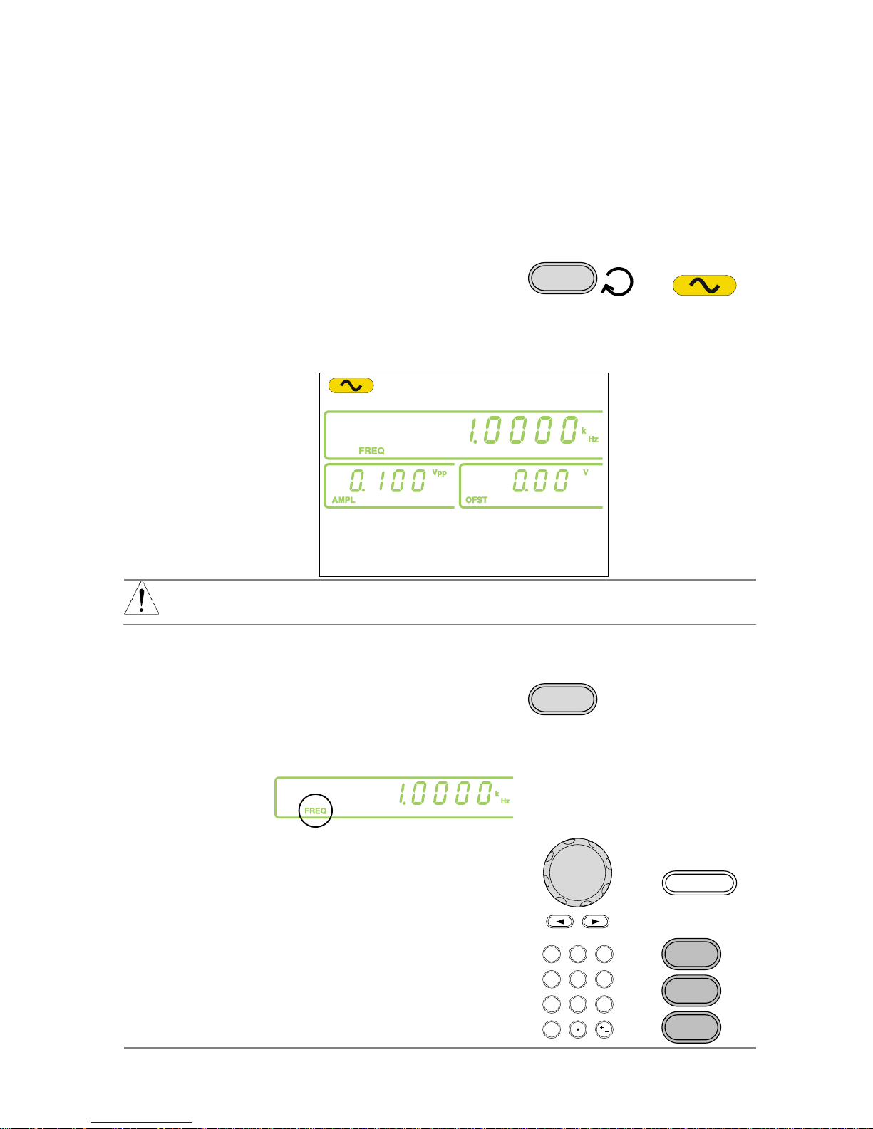
FGX-2005 FGX-2112

■ About Brands and Trademarks
“TEXIO” is the product brand name of our industrial electronic devices.
All company names and product names mentioned in this manual are the
trademark or the registered trademark of each company or group in each
country and region.
■ About the Instruction Manual
Permission from the copyright holder is needed to reprint the contents of this
manual, in whole or in part. Be aware that the product specifications and the
contents of this manual are subject to change for the purpose of improvement.

CONTENTS
USING THE PRODUCT SAFELY ············································ Ⅰ -Ⅳ
1. GETTING STARTED .......................................................................... 1
1-1. Main Features ................................................................................ 1
1-2. Panel Overview .............................................................................. 2
1-3. Rear Panel ..................................................................................... 5
1-4. Display ........................................................................................... 6
1-5. Setting up the Function Generator ................................................... 7
2. QUICK REFERENCE ......................................................................... 9
2-1. How to use the Digital Inputs ........................................................... 9
2-2. Selecting a Waveform ................................................................... 10
2-2-1. Sine Wave ................................................................ ................................. 10
2-2-2. Square Wave ............................................................................................. 10
2-2-3. Ramp Wave ............................................................................................... 11
2-3. ARB ............................................................................................. 11
2-4. Modulation ................................................................................... 12
2-4-1. AM (FGX-2112 only) .................................................................................. 12
2-4-2. FM (FGX-2112 only) .................................................................................. 12
2-4-3. FSK Modulation (FGX-2112 only) .............................................................. 13
2-5. Sweep (FGX-2112 only) ................................................................ 14
2-6. Counter (FGX-2112 only) .............................................................. 15
2-7. Save/Recall .................................................................................. 15
2-7-1. Save .......................................................................................................... 15
2-7-2. Recall ........................................................................................................ 15
2-8. Default Settings ............................................................................ 16
3. OPERATION ................................................................................... 17
3-1. Select a Waveform ....................................................................... 17
3-2. Setting the Frequency ................................................................... 17
3-3. Setting the Amplitude .................................................................... 18
3-4. Setting the DC Offset .................................................................... 19
3-5. Setting the Duty Cycle/Symmetry .................................................. 20
3-6. Setting the Load Impedance .......................................................... 21
3-7. Turning the Output On .................................................................. 22
3-8. Amplitude Modulation (AM) (FGX-2112 ) ........................................ 22
3-8-1. Selecting AM Modulation ........................................................................... 22
3-8-2. AM Carrier Waveform ................................................................................ 23
3-8-3. Setting the Carrier Frequency .................................................................... 23
3-8-4. Setting the Carrier Amplitude ..................................................................... 24
3-8-5. Setting the Modulating Wave Shape.......................................................... 25
3-8-6. Setting the Modulation Frequency (Rate) .................................................. 25
3-8-7. Modulation Depth ...................................................................................... 26
3-8-8. Setting the Modulation Source................................................................... 27
3-9. Frequency Modulation (FM)(FGX-2112 ) ........................................ 28
3-9-1. Selecting FM Modulation ........................................................................... 28
3-9-2. FM Carrier Waveform ................................................................................ 29
3-9-3. Setting the Carrier Frequency .................................................................... 29

3-9-4. Setting the Carrier Amplitude ..................................................................... 30
3-9-5. Setting the Modulating Wave Shape.......................................................... 31
3-9-6. Setting the Modulation Frequency (Rate) .................................................. 31
3-9-7. Frequency Deviation .................................................................................. 32
3-9-8. Setting the Modulation Source................................................................... 33
3-10. Frequency Shift Keying (FSK) Modulation (FGX-2112 ) ................. 34
3-10-1. Selecting FSK Modulation ....................................................................... 35
3-10-2. FSK Carrier Waveform ............................................................................ 35
3-10-3. FSK Carrier Frequency ............................................................................ 35
3-10-4. Setting the Carrier Amplitude ................................................................... 36
3-10-5. Setting the Hop Frequency ...................................................................... 37
3-10-6. FSK Rate ................................................................................................. 38
3-10-7. Setting the FSK Source ........................................................................... 39
3-11. Frequency Sweep (FGX-2112 ) .................................................... 40
3-11-1. Selecting Sweep ...................................................................................... 40
3-11-2. Setting Start and Stop Frequency ............................................................ 41
3-11-3. Sweep Mode ............................................................................................ 42
3-11-4. Sweep Rate ............................................................................................. 42
3-11-5. Setting the Sweep Source (Trigger) ......................................................... 43
3-12. Creating an Arbitrary Waveform ................................................... 44
3-13. Using the Frequency Counter ...................................................... 46
3-13-1. Selecting the Frequency Counter Function.............................................. 46
3-13-2. Selecting the Gate Time .......................................................................... 46
3-14. Using the SYNC Output Port ....................................................... 47
3-14-1. Connecting the SYNC Output Port .......................................................... 47
3-14-2. SYNC Output Signal ................................................................ ................ 47
3-15. Save and Recall State/ARB Waveform ......................................... 49
4. REMOTE INTERFACE ..................................................................... 51
4-1. Selecting the USB Remote Interface .............................................. 51
4-1-1. Remote control terminal connection .......................................................... 51
4-2. Command Syntax ......................................................................... 52
4-3. Command List .............................................................................. 56
4-3-1. System Commands ................................................................................... 57
4-3-1-1. *IDN? ................................................................................................... 57
4-3-1-2. *RST .................................................................................................... 57
4-3-2. Status Register Commands ....................................................................... 57
4-3-2-1. *CLS .................................................................................................... 57
4-3-3. APPLy Commands ..................................................................................... 57
4-3-3-1. SOURce[1]:APPLy:SINusoid ............................................................... 59
4-3-3-2. SOURce[1]:APPLy:SQUare................................................................. 59
4-3-3-3. SOURce[1]:APPLy:RAMP ................................ ................................... 59
4-3-3-4. SOURce[1]:APPLy:NOISe ................................................................... 60
4-3-3-5. SOURce[1]:APPLy:USER.................................................................... 60
4-3-3-6. SOURce[1]:APPLy? ............................................................................ 61
4-3-4. Output Commands .................................................................................... 61
4-3-4-1. SOURce[1]:FUNCtion .......................................................................... 61
4-3-4-2. SOURce[1]:FREQuency ...................................................................... 62
4-3-4-3. SOURce[1]:AMPLitude ........................................................................ 63
4-3-4-4. SOURce[1]:DCOffset ........................................................................... 64

4-3-4-5. SOURce[1]:SQUare:DCYCle ............................................................... 64
4-3-4-6. SOURce[1]:RAMP:SYMMetry ............................................................. 65
4-3-4-7. OUTPut................................................................................................ 66
4-3-4-8. SOURce[1]:OUTPut:LOAD .................................................................. 66
4-3-4-9. SOURce[1]:VOLTage:UNIT ................................................................. 66
4-3-5. Amplitude Modulation (AM) Commands .................................................... 67
4-3-5-1. SOURce[1]:AM:STATe ........................................................................ 68
4-3-5-2. SOURce[1]:AM:SOURce ..................................................................... 68
4-3-5-3. SOURce[1]:AM:INTernal:FUNCtion ..................................................... 69
4-3-5-4. SOURce[1]:AM:INTernal:FREQuency ................................................. 69
4-3-5-5. SOURce[1]:AM:DEPTh ....................................................................... 69
4-3-6. Frequency Modulation (FM) Commands ................................................... 70
4-3-6-1. SOURce[1]:FM:STATe ........................................................................ 71
4-3-6-2. SOURce[1]:FM:SOURce ..................................................................... 71
4-3-6-3. SOURce[1]:FM:INTernal:FUNCtion ..................................................... 71
4-3-6-4. SOURce[1]:FM:INTernal:FREQuency ................................................. 72
4-3-6-5. SOURce[1]:FM:DEViation ................................................................... 72
4-3-7. Frequency-Shift Keying (FSK) Commands ................................................ 73
4-3-7-1. SOURce[1]:FSKey:STATe................................................................... 74
4-3-7-2. SOURce[1]:FSKey:SOURce................................................................ 74
4-3-7-3. SOURce[1]:FSKey:FREQuency .......................................................... 75
4-3-7-4. SOURce[1]:FSKey:INTernal:RATE ..................................................... 75
4-3-8. Frequency Sweep Commands .................................................................. 76
4-3-8-1. SOURce[1]:SWEep:STATe ................................................................. 76
4-3-8-2. SOURce[1]:FREQuency:STARt .......................................................... 77
4-3-8-3. SOURce[1]:FREQuency:STOP ........................................................... 77
4-3-8-4. SOURce[1]:SWEep:SPACing .............................................................. 78
4-3-8-5. SOURce[1]:SWEep:RATE ................................................................... 78
4-3-8-6. SOURce[1]:SWEep:SOURce .............................................................. 78
4-3-9. Frequency Counter Commands................................................................. 79
4-3-9-1. COUNter:GATe ................................................................................... 79
4-3-9-2. COUNter:STATe .................................................................................. 79
4-3-9-3. COUNter:VALue? ................................................................................ 80
4-3-10. Arbitrary Waveform Commands ............................................................... 80
4-3-10-1. SOURce[1]:FUNCtion USER ............................................................. 81
4-3-10-2. DATA:DAC ........................................................................................ 81
4-3-11. Save and Recall Commands ................................................................... 82
4-3-11-1. *SAV .................................................................................................. 82
4-3-11-2. *RCL .................................................................................................. 82
5. APPENDIX ...................................................................................... 84
5-1. Error Messages ............................................................................ 84
5-2. FGX-2000 Series Specifications .................................................... 85
5-3. External Dimensions Figure .......................................................... 88
I
USING THE PRODUCT SAFELY
■ Preface
To use the product safely, read instruction manual to the end. Before using
this product, understand how to correctly use it. If you read the manuals but
you do not understand how to use it, ask us or your local dealer. After you
read the manuals, save it so that you can read it anytime as required.
■ Pictorial indication
The manuals and product show the warning and caution items required to
safely use the product. The following pictorial indication is provided.
Pictorial
indication
Some part of this product or the manuals may show this
pictorial indication. In this case, if the product is
incorrectly used in that part, a serious danger may be
brought about on the user's body or the product. To use
the part with this pictorial indication, be sure to refer to the
manuals.
WARNING
!
If you use the product, ignoring this indication, you may get
killed or seriously injured. This indication shows that the
warning item to avoid the danger is provided.
CAUTION
!
If you incorrectly use the product, ignoring this indication,
you may get slightly injured or the product may be
damaged. This indication shows that the caution item to
avoid the danger is provided.
Please be informed that we are not responsible for any damages to the user or
to the third person, arising from malfunctions or other failures due to wrong use
of the product or incorrect operation, except such responsibility for damages as
required by law.

II
USING THE PRODUCT SAFELY
WARNING
!
CAUTION
!
■ Do not remove the product's covers and panels
Never remove the product's covers and panels for any purpose.
Otherwise, the user's electric shock or fire may be incurred.
■ Warning on using the product
Warning items given below are to avoid danger to user's body and life and
avoid the damage or deterioration of the product. Use the product, observing
the following warning and caution items.
■ Warning items on power supply
● Power supply voltage
The rated power supply voltages of the product are 100, 120, 220 and
240VAC. The rated power supply voltage for each product should be
confirmed by reading the label attached on the back of the product or by the
“rated” column shown in the instruction manual. The specification of power
cord attached to the products is rated to 125VAC for all products which are
designed to be used in the areas where commercial power supply voltage is
not higher than 125VAC. Accordingly, you must change the power cord if
you want to use the product at the power supply voltage higher than 125VAC.
If you use the product without changing power cord to 250VAC rated one,
electric shock or fire may be caused. When you used the product equipped
with power supply voltage switching system, please refer to the corresponding
chapter in the instruction manuals of each product.
● Power cord
(IMPORTANT) The attached power cord set can be used for
this device only.
If the attached power cord is damaged, stop using the product and call us or
your local dealer. If the power cord is used without the damage being
removed, an electric shock or fire may be caused.
● Protective fuse
If an input protective fuse is blown, the product does not operate. For a
product with external fuse holder, the fuse may be replaced. As for how to
replace the fuse, refer to the corresponding chapter in the instruction
manual. If no fuse replacement procedures are indicated, the user is not
permitted to replace it. In such case, keep the case closed and consult us
or your local dealer. If the fuse is incorrectly replaced, a fire may occur.

III
USING THE PRODUCT SAFELY
■ Warning item on Grounding
If the product has the GND terminal on the front or rear panel surface, be sure
to ground the product to safely use it.
■ Warnings on Installation environment
● Operating temperature and humidity
Use the product within the operating temperature indicated in the “rating”
temperature column. If the product is used with the vents of the product
blocked or in high ambient temperatures, a fire may occur. Use the product
within the operating humidity indicated in the “rating” humidity column.
Watch out for condensation by a sharp humidity change such as transfer to a
room with a different humidity. Also, do not operate the product with wet
hands. Otherwise, an electric shock or fire may occur.
● Use in gas
Use in and around a place where an inflammable or explosive gas or steam is
generated or stored may result in an explosion and fire. Do not operate the
product in such an environment. Also, use in and around a place where a
corrosive gas is generated or spreading causes a serious damage to the
product. Do not operate the product in such an environment.
● Installation place
Do not insert metal and inflammable materials into the product from its vent
and spill water on it. Otherwise, electric shock or fire may occur.
■ Do not let foreign matter in
Do not insert metal and inflammable materials into the product from its vent
and spill water on it. Otherwise, electric shock or fire may occur.
■ Warning item on abnormality while in use
If smoke or fire is generated from the product while in use, stop using the
product, turn off the switch, and remove the power cord plug from the outlet.
After confirming that no other devices catch fire, ask us or your local dealer.

IV
USING THE PRODUCT SAFELY
■ Input / Output terminals
Maximum input to terminal is specified to prevent the product from being
damaged. Do not supply input, exceeding the specifications that are indicated
in the "Rating" column in the instruction manual of the product. Also, do not
supply power to the output terminals from the outside. Otherwise, a product
failure is caused.
■ Calibration
Although the performance and specifications of the product are checked under
strict quality control during shipment from the factory, they may be deviated
more or less by deterioration of parts due to their aging or others.
It is recommended to periodically calibrate the product so that it is used with its
performance and specifications stable. For consultation about the product
calibration, ask us or your local dealer.
■ Daily Maintenance
When you clean off the dirt of the product covers, panels, and knobs, avoid
solvents such as thinner and benzene. Otherwise, the paint may peel off or
resin surface may be affected. To wipe off the covers, panels, and knobs, use
a soft cloth with neutral detergent in it.
During cleaning, be careful that water, detergents, or other foreign matters do
not get into the product.
If a liquid or metal gets into the product, an electric shock and fire are caused.
During cleaning, remove the power cord plug from the outlet.
Use the product correctly and safely, observing the above warning and caution
items. Because the instruction manual indicates caution items even in individual
items, observe those caution items to correctly use the product.
If you have questions or comments about the manuals, ask us or E-Mail us.

1
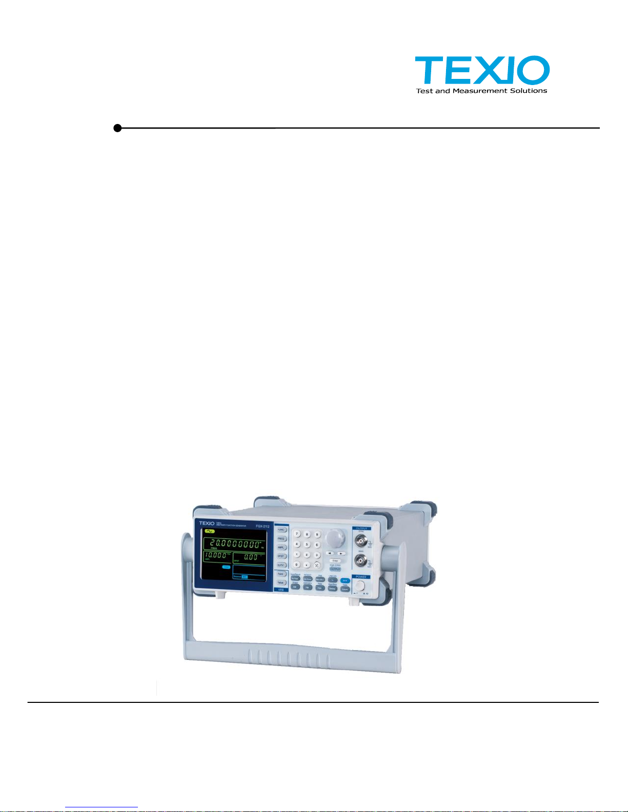
1. GETTING STARTED
The Getting started chapter introduces the function generator’s main features,
appearance and introduces a quick instructional summary of some of the
basic functions. For comprehensive operation instructions, please see the
operation chapter.
1-1. Main Features
Model name
FGX-2005
FGX-2112
Frequency Range
0.1Hz~5MHz
0.1Hz~12MHz
Output waveform
Sine, Square, Ramp, Noise, ARB
Amplitude range
1 mVpp to 10 Vpp (into 50Ω)
2 mVpp to 20 Vpp (open-circuit)
Variable Offset
✓
✓
Variable Duty
✓
✓
SYNC (TTL) output
✓
✓
Save/Recall
✓
✓
Sweep operation
—
✓
AM /FM / FSK
—
✓
Frequency Counter
—
✓
ARB
✓
✓
USB Interface
✓
✓
Performance
• DDS technology using an FPGA provides high resolution
waveforms
• 12MHz/5MHz DDS (Direct Digital Synthesis) signal
output series
• 0.1Hz resolution
• Full Function Arbitrary Waveform Capability
20 MSa/s sample rate
10 MHz repetition rate
4 k-point waveform length
10-bit amplitude resolution
Ten 4k waveform memories
Features
• Sine, Square, Ramp, Noise
• Int/Ext AM, FM, FSK modulation
• Modulation/sweep signal output
• Save/recall 10 groups of setting memories
• Output overload protection
Interface
• USB interface as standard
• 3.5 inch LCD
2
1-2. Panel Overview
FGX-2112 Front Panel
ARB
OUTPUT
50W
50W
SYNC
MAIN
OUTPUT
POWERSave/Recall INT/EXT Hop LIN/LOG
Shape DEP /DEV Rate Start/Stop Gate
FUNC
FREQ
AMPL
OFST
DUTY
Point
Value
0
7 8 9
4 5 6
1 2 3
/
Hz/Vpp kHz/Vrms MHz/dBm % Shift
AM FM FSK Sweep Count
OUTPUT
Enter
Arbitrary Function Generator
LCD
Display
Number
pad
Scroll
Wheel
MAIN
output port
ARB keys Power
button
Output
control key
Enter key
Arrow keys SYNC output
port
Operation
keys
Function
keys
High-Z/50Ω
LCD display
3.5 inch, 3 color LCD display.
Keypad
0
/
321
4
7 8
5
9
6
The digital keypad is used to enter values
and parameters. The keypad is often
used in conjunction with the selection
keys and variable knob.
Scroll Wheel
The scroll wheel is used to edit values
and parameters in steps of 1 digit. Used
in conjunction with the arrow keys.
Decrease Increase
Arrow keys
Used to select digits when editing
parameters.
Output ports
OUTPUT
50
W
50
W
SYNC
MAIN
OUTPUT
SYNC output port (50Ω impedance).
Main output port (50Ω impedance).
Enter key
Enter
Used to confirm input values.
Power button
POWER
Turns the instrument power on/off.
3
Output control
key
OUTPUT
Turns the output on/off.
Load
Impedance
Shift
+
High Z/50Ω
OUTPUT
Toggles the load impedance between
50Ω and High-Z.
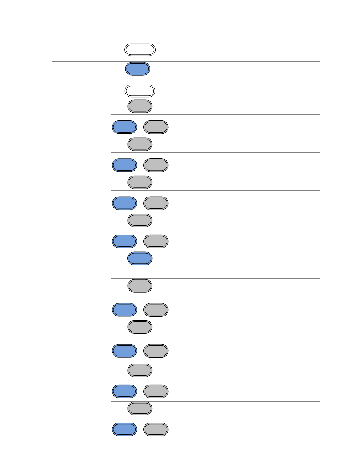
Operation keys
Hz/Vpp
Selects Hz or Vpp units.
Shift
+
Save/Recall
Hz/Vpp
Saves or recalls waveforms from memory.
kHz/Vrms
Selects kHz or Vrms units.
Shift
+
INT/EXT
kHz/Vrms
Sets the source to internal or external for
the modulation and FSK functions*.
MHz/dBm
Selects MHz or dBm units.
Shift
+
Hop
MHz/dBm
Sets the “Hop” frequency for FSK
modulation*.
%
Selects % units.
Shift
+
LIN/LOG
%
Sets the sweep to linear or logarithmic*.
Shift
The shift key is used to select the
secondary functions on the operation
keys.
AM
The AM key is used to turn AM
modulation on/off*.
Shift
+
Shape
AM
Selects the modulation waveform*.
FM
The FM key is used to turn FM
modulation on/off*.
Shift
+
DEP/DEV
FM
Selects the modulation depth or the
frequency deviation*.
FSK
Selects FSK modulation*.
Shift
+
Rate
FSK
Sets the AM, FM, FSK modulation and
sweep function rate*
Sweep
Selects the Sweep function*.
Shift
+
Start/Stop
Sweep
Sets the Start or Stop frequency*.
4
Count
Turns the frequency counter on/off*.
Shift
+
Gate
Count
Sets the frequency counter gate time*.
ARB edit keys
ARB
Value
Point
Arbitrary waveform editing keys.
The Point key sets the ARB point
numbers.
The Value key sets the amplitude value of
the selected point.
Function keys
FUNC
The FUNC key is used to select the
output waveform type:
Sine, Square, Ramp, Noise, ARB.
FREQ
Sets the frequency of the selected
waveform.
AMPL
Sets the amplitude of the selected
waveform.
OFST
The OFST sets the DC offset for the
selected waveform.
DUTY
The DUTY key sets the duty cycle of
square and ramp waveforms.
*indicates functions/features for the FGX-2112 only.
5
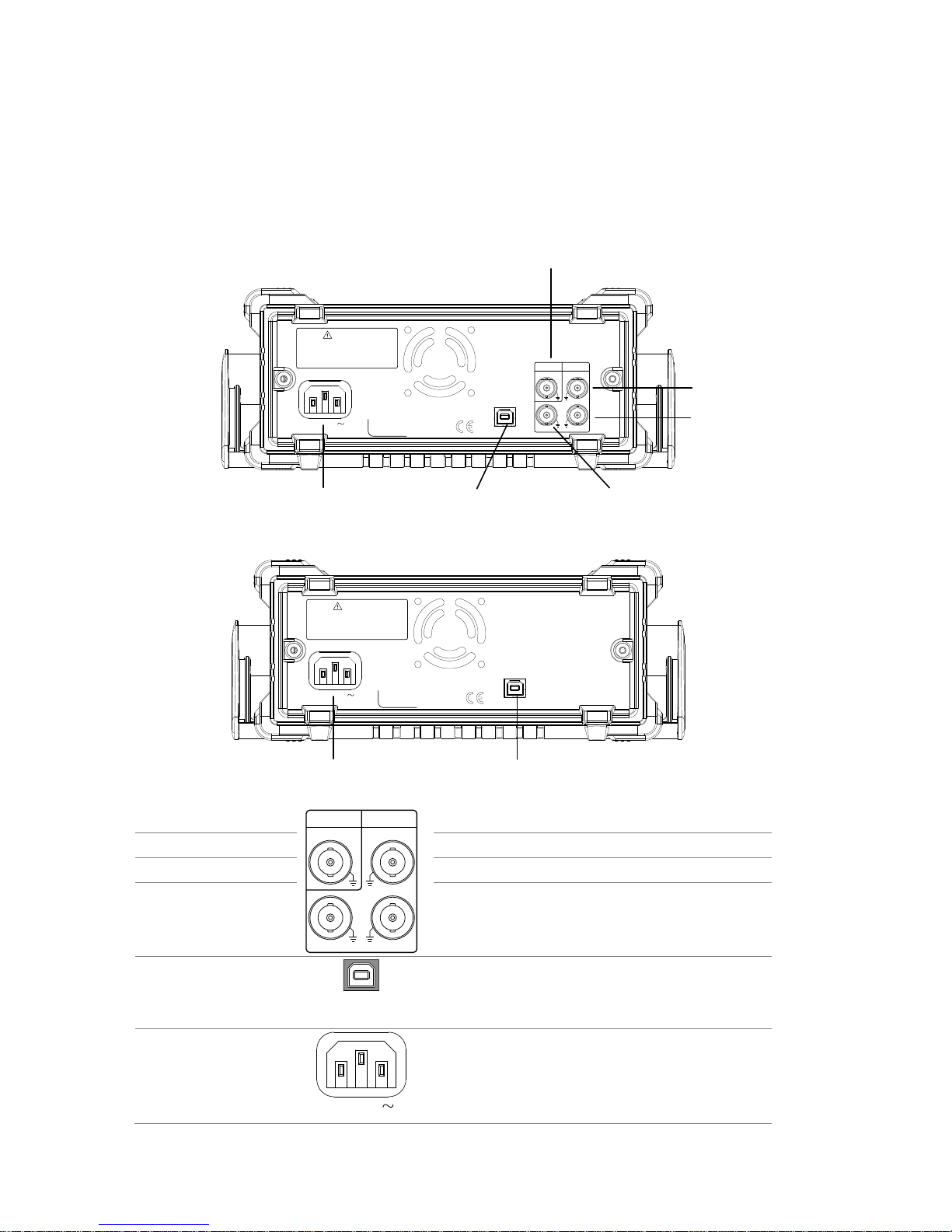
1-3. Rear Panel
FGX-2112 Rear Panel
NO OPERATOR SERVICEABLE COMPONENTS INSIDE.
DO NOT REMOVE COVERS. REFER SERVICING TO
TO AVOID ELECTRIC SHOCK THE POWER CORD PROTECTIVE
GROUNDING CONDUCTOR MUST BE CONNECTED TO GROUND.
WARNING
QUALIFIED PERSONNEL.
SER.NO. LABEL
AC 100-240V
50-60Hz 25VA
OUTPUT INPUT
MOD Counter
Trigger MOD
MOD input
Trigger input
MOD output
Type B USB portPower socket
Counter input
FGX-2005 Rear Panel
NO OPERATOR SERVICEABLE COMPONENTS INSIDE.
DO NOT REMOVE COVERS. REFER SERVICING TO
TO AVOID ELECTRIC SHOCK THE POWER CORD PROTECTIVE
GROUNDING CONDUCTOR MUST BE CONNECTED TO GROUND.
WARNING
QUALIFIED PERSONNEL.
SER.NO. LABEL
AC 100-240V
50-60Hz 25VA
Type B USB portPower socket
MOD output
OUTPUT INPUT
MOD Counter
Trigger MOD
Modulation output port.
Counter input
Counter input port.
MOD input
Modulation input port.
Trigger input
Trigger input port.
Type B USB port
The type B USB port is used to
connect the function generator to a
PC for remote control.
Power Socket
Input
AC 100-240V
50-60Hz 25VA
Power input: 100~240V AC
50~60Hz.
6
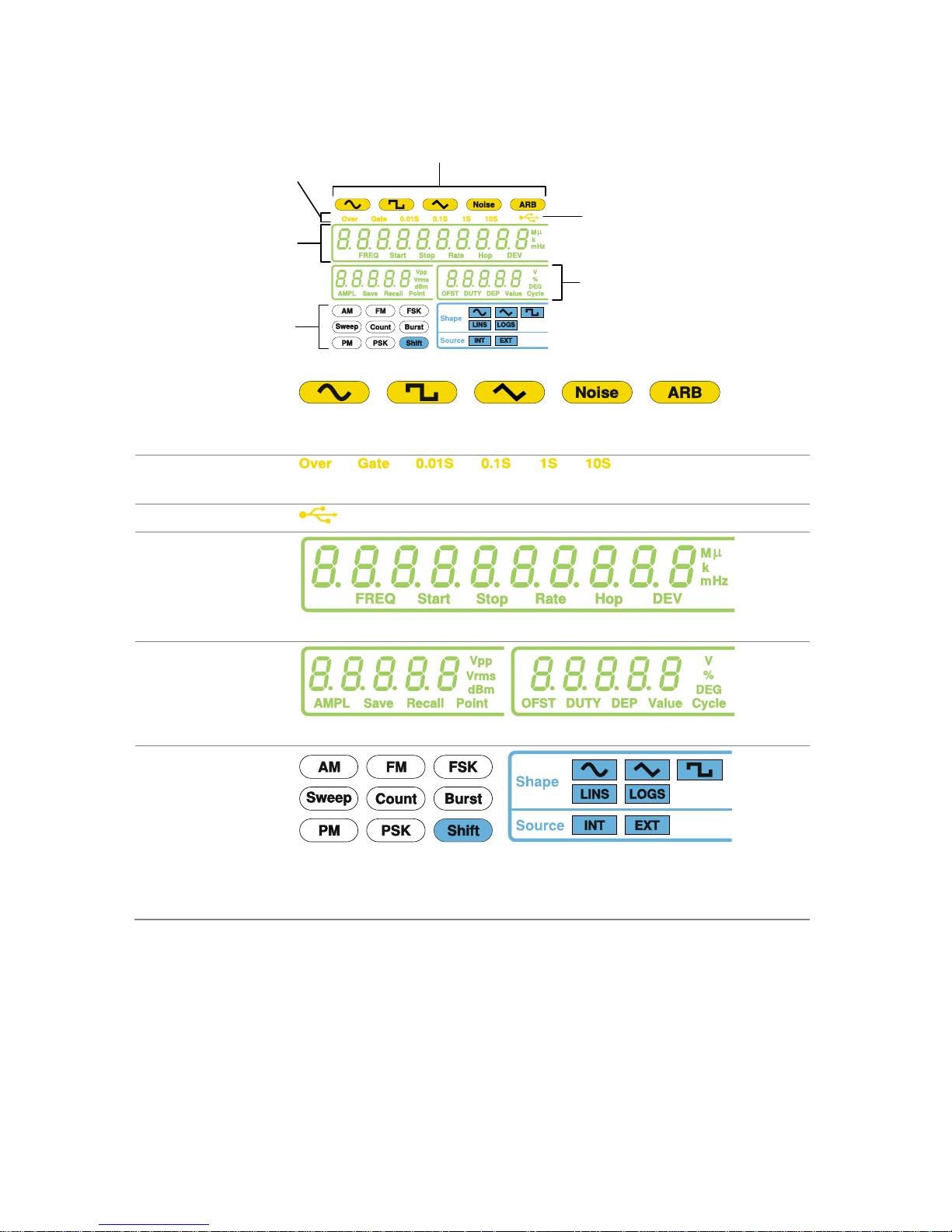
1-4. Display
Waveform type
Counter settings
USB icon
Frequency display
Secondary parameter
display
Modulation, sweep,
counter menu
Waveform type
Press the function key to cycle through different output
waveforms.
Counter settings
Gate time counter settings*.
USB icon
Shows the USB interface status.
Frequency
Display
Displays the main waveform frequency settings.
Secondary
parameter
display
Displays secondary waveform parameters and settings.
Modulation,
sweep, counter
menu
Displays the modulation, sweep and counter functions
as well as the modulating waveform and source*.
*indicates functions/features for the FGX-2112 only.
7
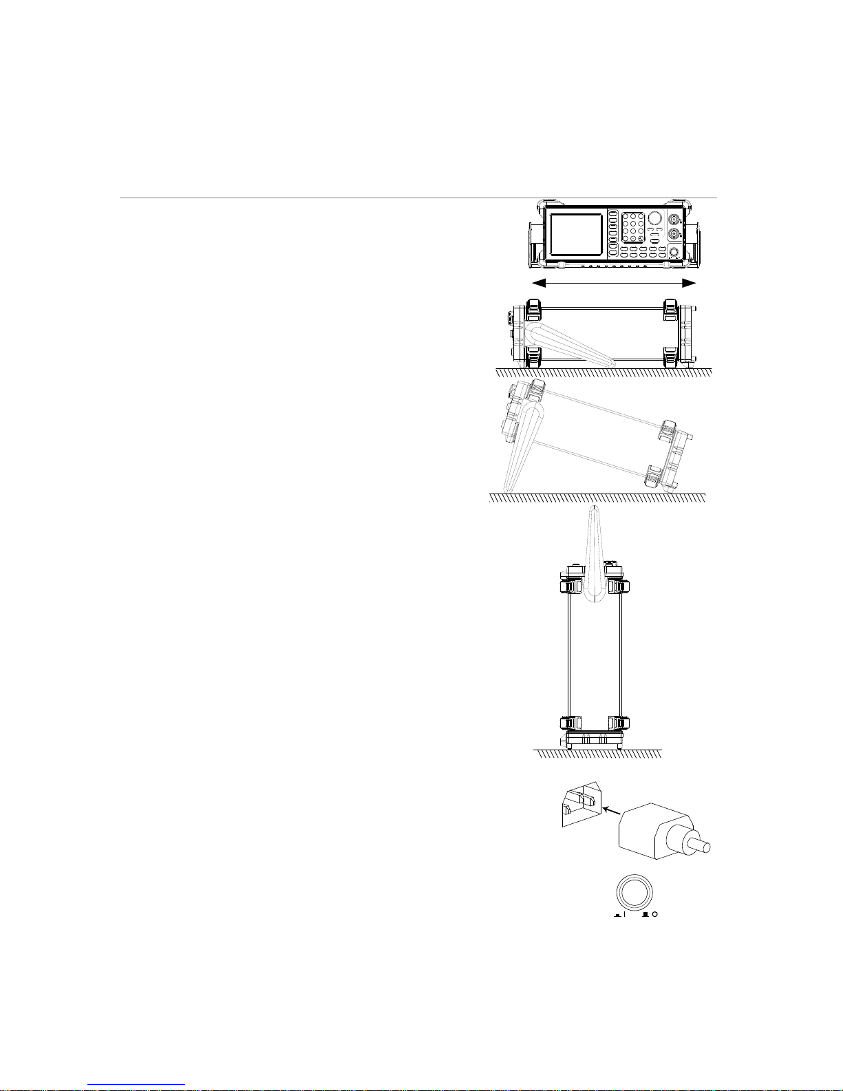
1-5. Setting up the Function Generator
Background
This section describes how adjust the handle and
power up the function generator.
Adjusting the
stand
Pull out the handle
sideways and rotate it.
ARB
OUTPUT
50W
50
W
SYNC
MAIN
OUTPUT
POWER
Save/Recall INT/EXT Hop LIN/LOG
Shape DEP/DEV Rate Start/Stop Gate
FUNC
FREQ
AMPL
OFST
DUTY
Point
Value
0
7 8 9
4 5 6
1 2 3
/
Hz/Vpp kHz/Vrms MHz/dBm % Shift
AM FM FSK Sweep Count
OUTPUT
Enter
Arbitrary Function Generator
Place the FGX
horizontally.
Place the handle upright
to tilt the stand.
Place the handle vertically
to hand carry.
Power Up
1. Connect the power cord to the
socket on the rear panel.
2. Press the power button on the
front panel.
POWER
3. The instrument will turn on and load the last
settings that were used before the power was
turned off.

8
The function generator is now ready to be used.
9
2. QUICK REFERENCE
This chapter lists operation shortcuts and default factory settings. Use this
chapter as a handy reference for instrument functions. This chapter is to be
used as a quick reference; for detailed explanations on parameters, settings
and limitations, please see the operation chapter (page 17) or specifications
(page 85).
2-1. How to use the Digital Inputs
Background
The FGX-2000 has three main types of digital inputs: the
number pad, arrow keys and the scroll wheel. The
following instructions will show you how to use the digital
inputs to edit parameters.
1. First select the function that
must be edited pressing
one of the function or ARB
keys. The selected function
will flash.
ARB
OUTPUT
50W
50W
SYNC
MAIN
OUTPUT
POWERSave/Recall
FUNC
FREQ
AMPL
OFST
DUTY
Point
Value
0
7 8 9
4 5 6
1 2 3
/
Hz/Vpp kHz/Vrms MHz/ dBm % Shift
OUTPUT
Enter
ARB keys
Function
keys
2. To edit a parameter, use the
arrow keys to move the
cursor to the digit that
needs to be edited.
cursor
3. Use the scroll wheel to
increment the parameter by
the resolution of the digit
under the cursor.
In the example above, the
scroll wheel will increment
the parameter in 0.1 volt
increments.
Clockwise increases the
value, counterclockwise
decreases the value.
10
4. Press the Enter key to
confirm the new parameter
value.
Enter
5. Alternatively, the number
pad can be used to set the
value of the selected
parameter.
0
/
321
4
7 8
5
9
6
6. To finish editing with the
number pad, select the unit
with one of the unit keys.
(Hz, kHz, MHz, Vpp, Vrms,
dBm, %)
Hz/Vpp
kHz/Vrms
MHz/dBm
%
2-2. Selecting a Waveform
2-2-1. Sine Wave
Example: Sine Wave, 10kHz, 1Vpp, 2Vdc
Output
50
W
MAIN
1. Press the FUNC key
repeatedly to select the
Sine wave.
FUNC
→
2. Press FREQ > 1 > 0 >
kHz.
FREQ
1
0
kHz/Vrms
3. Press AMPL > 1 > Vpp.
AMPL
1
Hz/Vpp
4. Press OFST > 2 > Vpp.
OFST
2
Hz/Vpp
5. Press the OUTPUT key.
OUTPUT
2-2-2. Square Wave
Example: Square Wave, 10kHz, 3Vpp, 75% duty cycle
Output
50
W
MAIN
1. Press the FUNC key
repeatedly to select the
Square wave.
FUNC
→
2. Press FREQ > 1 > 0 >
kHz.
FREQ
1
0
kHz/Vrms
3. Press AMPL > 3 > Vpp.
AMPL
3
Hz/Vpp
4. Press DUTY > 7 > 5 >
%.
DUTY
7
5
%
11
5. Press the output key.
OUTPUT
2-2-3. Ramp Wave
Example: Ramp Wave, 10kHz, 3Vpp, 25% symmetry
Output
50
W
MAIN
1. Press the FUNC key
repeatedly to select the
Ramp wave.
FUNC
→
2. Press FREQ > 1 > 0 >
kHz.
FREQ
1
0
kHz/Vrms
3. Press AMPL > 3 > Vpp.
AMPL
3
Hz/Vpp
4. Press DUTY > 2 > 5 >
%.
DUTY
2
5
%
5. Press the OUTPUT key.
OUTPUT
2-3. ARB
Example: 2 ARB points, 10 kHz, 1Vpp.
Output
50
W
MAIN
1. Press the FUNC key
repeatedly to select the
ARB wave.
FUNC
→
2. Press FREQ > 1 > 0 >
kHz.
FREQ
1
0
kHz/Vrms
3. Press AMPL > 1 > Vpp.
AMPL
1
Hz/Vpp
4. Press Point > 0 > Enter.
Point
0
Enter
5. Press Value > 5 > 1 >1
> Enter.
Value
511
Enter
6. Press Point > 1 > Enter.
Point
1
Enter
7. Press Value > ± > 5 > 1
>1 > Enter.
(-511)
Value
/
511
Enter
8. Press the OUTPUT key.
OUTPUT
12
2-4. Modulation
2-4-1. AM (FGX-2112 only)
Example: AM modulation. 100Hz modulating square wave. 1 Vpp, 1kHz
Sine wave carrier. 70% modulation depth. Internal source signal.
Output
50
W
MAIN
1. Press the FUNC key
repeatedly to select the
Sine wave.
FUNC
→
2. Press FREQ > 1 > kHz.
FREQ
1
kHz/Vrms
3. Press AMPL > 1 > Vpp.
AMPL
1
Hz/Vpp
4. Press AM.
AM
5. Press Shift > INT/EXT >
select INT source.
Shift
+
INT/EXT
kHz/Vrms
6. Press Shift > Shape
repeatedly to select the
Square wave.
Shift
+
Shape
AM
→
7. Press Shift > Rate > 1 >
0 > 0 > Hz.
Shift
+
Rate
FSK
100
Hz/Vpp
8. Press Shift >
DEP/DEV> 7 > 0 > %.
Shift
+
DEP/DEV
FM
7
0
%
9. Press the OUTPUT key.
OUTPUT
10. Press AM again to
deselect the AM
function.
AM
2-4-2. FM (FGX-2112 only)
Example: FM modulation. 100Hz modulating square wave. 1Vpp, 1kHz
Sine wave carrier. 100 Hz frequency deviation. Internal Source.
Output
50
W
MAIN
1. Press the FUNC key
repeatedly to select the
Sine wave.
FUNC
→
2. Press FREQ > 1 > kHz.
FREQ
1
kHz/Vrms
13
3. Press AMPL > 1 > Vpp.
AMPL
1
Hz/Vpp
4. Press FM.
FM
5. Press Shift > INT/EXT >
select INT source.
Shift
+
INT/EXT
kHz/Vrms
6. Press Shift > Shape
repeatedly to select
Square wave.
Shift
+
Shape
AM
→
7. Press Shift > Rate > 1 >
0 > 0 > Hz.
Shift
+
Rate
FSK
1
0
0
Hz/Vpp
8. Press Shift >
DEP/DEV> 1 > 0 > 0>
Hz
Shift
+
DEP/DEV
FM
1
0
0
Hz/Vpp
9. Press the OUTPUT key.
OUTPUT
10. Press FM again to
deselect the AM
function.
FM
2-4-3. FSK Modulation (FGX-2112 only)
Example: FSK modulation. 10Hz Hop frequency. 1Vpp, 1kHz Ramp carrier
wave. 100 Hz Rate (modulation frequency). Internal Source.
Output
50
W
MAIN
1. Press the FUNC key
repeatedly to select the
Ramp wave.
FUNC
→
2. Press FREQ > 1 > kHz.
FREQ
1
kHz/Vrms
3. Press AMPL > 1 > Vpp.
AMPL
1
Hz/Vpp
4. Press FSK.
FSK
5. Press Shift > INT/EXT >
select INT source.
Shift
+
INT/EXT
kHz/Vrms
6. Press Shift > Rate > 1 >
0 > 0 > Hz.
Shift
+
Rate
FSK
1
0
0
Hz/Vpp
14
7. Press Shift > Hop > 1 >
0 > Hz.
Shift
+
Hop
MHz/dBm
1
0
Hz/Vpp
8. Press the OUTPUT key.
OUTPUT
9. Press FSK again to
deselect the FSK
function.
FSK
2-5. Sweep (FGX-2112 only)
Example: Frequency Sweep. Start Frequency 1Hz, Stop Frequency 1MHz.
1Hz Rate. 1Vpp. Linear Sweep.
Output
50
W
MAIN
1. Press the FUNC key
repeatedly to select the
Ramp wave.
FUNC
→
2. Press AMPL > 1 > Vpp.
AMPL
1
Hz/Vpp
3. Press Sweep.
Sweep
4. Press Shift > INT/EXT >
select INT source.
Shift
+
INT/EXT
kHz/Vrms
5. Press Shift > Start/Stop
select Start> 1 > Hz.
Shift
+
Start/Stop
Sweep
1
Hz/Vpp
6. Press Shift > Start/Stop
select Stop> 1 > MHz.
Shift
+
Start/Stop
Sweep
1
MHz/dBm
7. Press Shift > Rate > 1 >
Hz.
Shift
+
Rate
FSK
1
Hz/Vpp
8. Press Shift > LIN/LOG
> select LINS.
Shift
+
LIN/LOG
%
9. Press the OUTPUT key.
OUTPUT
10. Press Sweep again to
deselect the sweep
function.
Sweep
15
2-6. Counter (FGX-2112 only)
Example: Frequency counter function, gate time 1s.
Input
OUTPUT INPUT
MOD Counter
FSK MOD
1. Press the Count key.
Count
2. Press Shift > Gate
repeatedly to select the
1S gate time.
Shift
+
Gate
Count
3. Connect the signal to the counter input signal.
4. Press Count again to
deselect the counter
function.
Count
2-7. Save/Recall
2-7-1. Save
Example: Save waveform to memory.
1. Press Shift >
Save/Recall. Select
Save.
Shift
+
Save/Recall
Hz/Vpp
2. Turn the scroll wheel
and choose a save
number.
3. Press Enter to confirm
the save file number.
Enter
2-7-2. Recall
Example: Recall waveform from memory.
1. Press Shift >
Save/Recall. Select
Recall.
Shift
+
Save/Recall
Hz/Vpp
2. Turn the scroll wheel
and choose a saved file
number.
3. Press Enter to confirm
the recall.
Enter

16
2-8. Default Settings
The default settings can be loaded by using the *RST command or
pressing the following keys:Duty,1,2,3,4,8,Enter
Output Config.
Function
Sine wave
Frequency
1kHz
Amplitude
100mVpp
Offset
0.00Vdc
Output units
Vpp
Output terminal
50Ω
Load impedance
50Ω
Modulation
(AM/FM/FSK)
Carrier Wave
1kHz Sine wave
Modulation waveforms
100Hz Sine wave
AM Depth
100%
FM Deviation
10Hz
FSK Hop Frequency
100Hz
FSK Frequency
500Hz
Modulation Status
Off
Sweep
Start/Stop frequency
100Hz/1kHz
Sweep time
1s Sweep rate
100Hz
Sweep type
Linear
Sweep status
Off
System settings
Power off signal
On
Display mode
On
Error queue
cleared
Memory settings (ARB)
No change
Output
Off
Interface config.
USB
CDC
Calibration
Calibration Menu
Restricted
17
3. OPERATION
The Operation chapter shows how to output basic waveforms and create ARB
waveforms. The FGX-2112 can also perform advanced functions such as
modulation, sweep, FSK and counter functions.
3-1. Select a Waveform
The FGX-2000 can output four standard waveforms: sine, square, ramp and
noise waveforms.
Panel Operation
1. Press the FUNC key
repeatedly to select a
standard waveform
(Sine, Square, Ramp,
Noise).
FUNC
→
Example:
Sine wave
Note
The modulation, FSK, sweep and counter functions must
be disabled before a standard waveform can be output.
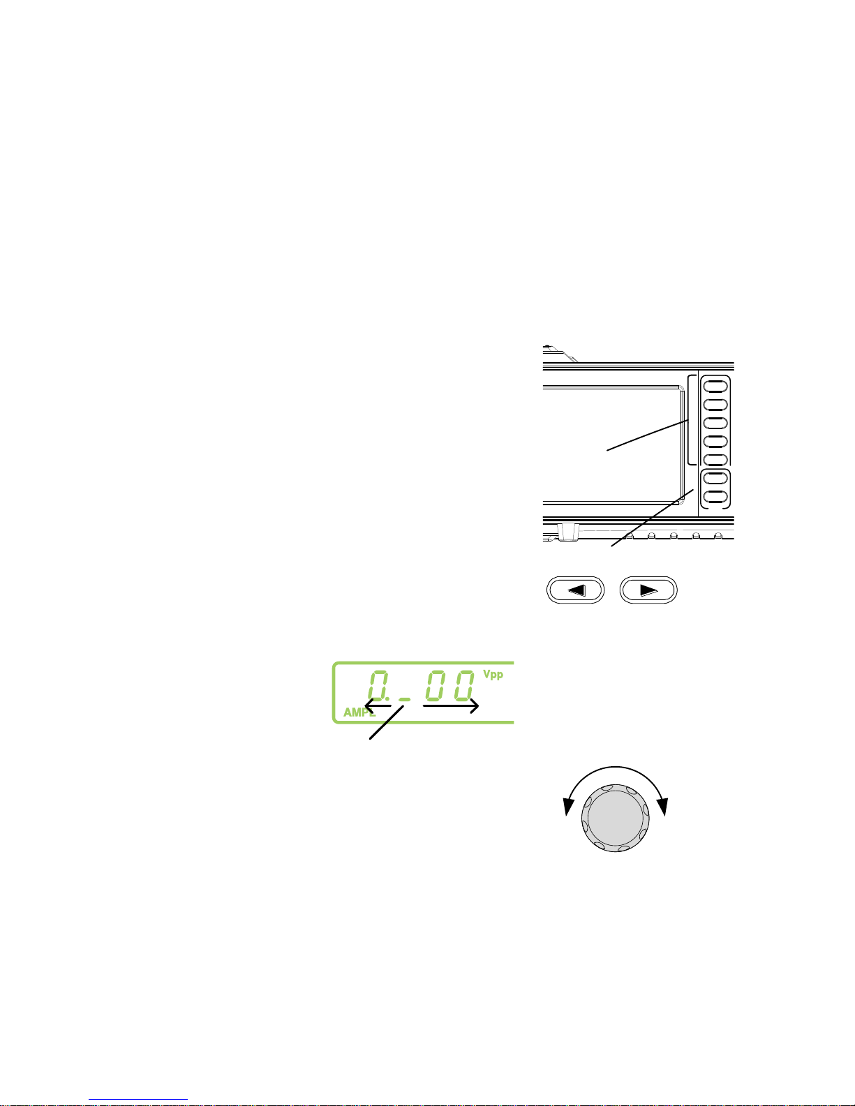
3-2. Setting the Frequency
Panel
Operation
Press the FREQ key.
FREQ
The FREQ icon will flash in the frequency display
area.
Use the arrow keys, scroll
wheel and Enter key to edit
the frequency.
→
Enter
Use the keypad and the
relevant unit key to enter a
new frequency.
0
/
321
4
7 859
6
→
Hz/Vpp
kHz/Vrms
MHz/dBm
18
Range
Sine
0.1Hz ~ 12MHz*
Square
0.1Hz ~ 12MHz*
Ramp
0.1Hz ~ 1MHz
*limited to 5MHz for the FGX-2005, 12MHz for the
FGX-2112.
Example:
FREQ = 1kHz
3-3. Setting the Amplitude
Panel Operation
1. Press the AMPL key.
AMPL
2. The AMPL icon will flash in the secondary display
area.
3. Use the arrow keys,
scroll wheel and Enter
key to edit the amplitude.
→
Enter
Use the keypad and the
relevant unit key to enter
a new amplitude.
0
/
321
4
7 859
6
→
Hz/Vpp
kHz/Vrms
MHz/dBm
Range
No load
2mVpp~20Vpp
50Ω Load
1mVpp~10Vpp
19
Example:
AMPL= 1Vpp
3-4. Setting the DC Offset
Panel Operation
1. Press the OFST key.
OFST
2. The OFST icon will flash in the secondary display
area.
3. Use the arrow keys,
scroll wheel and Enter
key to edit the offset.
→
Enter
Use the keypad and the
Vpp key to enter a new
offset.
0
/
321
4
7 859
6
→
Hz/Vpp
Range
No Load (AC+DC)
±10Vpk
50Ω Load (AC+DC)
±5 Vpk
Example:
OFST= 1VDC
20
3-5. Setting the Duty Cycle/Symmetry
Background
The DUTY key sets the duty cycle or symmetry of
the standard square or ramp waveforms.
Panel Operation
1. Ensure a square or ramp waveform is
selected.
Page 17
2. Press the DUTY key.
DUTY
3. The duty icon will flash in the secondary display
area.
4. Use the arrow keys,
scroll wheel and Enter
key to edit the duty
cycle/symmetry.
→
Enter
Use the keypad and the
% key to enter a new duty
cycle/symmetry.
0
/
321
4
7 859
6
→
%
Duty Cycle
Range
≤ 100kHz
1.0% ~ 99.0%
≤ 5MHz
20.0% ~ 80.0%
≤ 10MHz
40.0 ~ 60.0%
≤ 12MHz
50.0% (fixed)
10% 50% 90%
Symmetry
Range
All frequencies
0% ~ 100%
0% 50% 100%
Example:
DUTY= 50.0%
21
3-6. Setting the Load Impedance
Background
The FGX-2000 load impedance can be set to 50Ω
or to High-Z. When the load impedance is set to
high-Z the effect output is doubled compared to the
default 50Ω. For example, when the amplitude is set
to 10Vpp (impedance of 50Ω) when the load
impedance is switched to high-Z, the amplitude
becomes 20Vpp.
Note
dBm units are not supported for the high-Z load
impedance.
If the amplitude unit is dBm, and you switch to the
High-Z load impedance, the amplitude unit will
automatically change to Vpp.
If the load impedance is set to High-Z, you cannot
set the amplitude units to dBm. Change the load
impedance back to 50Ω first.
Panel Operation
1. To toggle the load impedance
between 50 and High-Z, press
SHIFT+OUTPUT.
Shift
+
High Z/50Ω
OUTPUT
2. The selected load impedance will flash momentarily
on the display.
50 Ω:
High-Z:

22
3-7. Turning the Output On
Panel Operation
1. Press the OUTPUT key to
output the selected waveform.
High Z/50Ω
OUTPUT
The output key will turn green when the output is
on.
OUTPUT OUTPUT
2. To disable the output, press the
OUTPUT key again.
High Z/50Ω
OUTPUT
The output key will turn off when the output is
disabled.
OUTPUT OUTPUT
3-8. Amplitude Modulation (AM) (FGX-2112 )
An AM waveform is produced from a carrier waveform and a modulating
waveform. The amplitude of the modulated carrier waveform depends on the
amplitude of the modulating waveform. The FGX-2112 function generator can
set the carrier frequency, amplitude and offset as well as internal or external
modulation sources.
AM modulation is only applicable for the FGX-2112 function generators.
Modulated Carrier
Waveform
Modulating
waveform
3-8-1. Selecting AM Modulation
Panel Operation
1. Press the AM key.
AM
2. The modulation, sweep and counter menu display
will appear. The AM icon indicates that the AM
function is active.

23
Example:
AM activated
Note
AM modulation can be deactivated by pressing the AM
key again.
3-8-2. AM Carrier Waveform
Background
The FUNC key selects the AM carrier waveform. Sine,
square or ramp waveforms can be used as the carrier.
The default waveform is set to sine. Noise is not available
as a carrier shape. Before the carrier shape can be
selected, ensure AM is active, page 38.
Selecting the
Carrier Shape
1. Press the FUNC key
repeatedly to select a
carrier waveform (Sine,
Square, Ramp).
FUNC
→
Range
AM Carrier Shape
sine, square, ramp
3-8-3. Setting the Carrier Frequency
Panel Operation
1. Press FREQ key.
FREQ
2. The FREQ icon will flash in the frequency display
area.
3. Use the arrow keys, scroll
wheel and Enter key to edit
the frequency.
→
Enter
Use the keypad and the
relevant unit key to enter a
new frequency.
0
/
321
4
7 859
6
→
Hz/Vpp
kHz/Vrms
MHz/dBm

24
Range
Sine
0.1Hz ~ 12MHz
Square
0.1Hz ~ 12MHz
Ramp
0.1Hz ~ 1MHz
Example:
FREQ = 1kHz
3-8-4. Setting the Carrier Amplitude
Panel Operation
1. Press AMPL key.
AMPL
2. The AMPL icon will flash in the secondary display
area.
3. Use the arrow keys, scroll
wheel and Enter key to edit
the amplitude.
→
Enter
Use the keypad and the
relevant unit key to enter a
new amplitude.
0
/
321
4
7 859
6
→
Hz/Vpp
kHz/Vrms
MHz/dBm
Range
No Load
2mVpp~20Vpp
50Ω Load
1mVpp~10Vpp
Example:
AMPL= 1Vpp

25
3-8-5. Setting the Modulating Wave Shape
The FGX-2112 has sine, square and Triangle modulating waveform shapes.
Sine waves are the default wave shape.
Panel Operation
1. Press the Shift + Shape
key repeatedly to select a
shape waveform.
Shift
+
Shape
AM
→
2. The waveform Shape is displayed in blue at the
bottom of the panel.
Restrictions
Square
50% duty cycle
Triangle
50% symmetry
Example:
Shape = Sine
3-8-6. Setting the Modulation Frequency (Rate)
Panel Operation
1. Press the Shift + Rate key.
Shift
+
Rate
FSK
2. The Rate icon will flash in the frequency display
area.
3. Use the arrow keys, scroll
wheel and Enter key to edit
the rate.
→
Enter
Use the keypad and the
relevant unit key to enter a
new rate.
0
/
321
4
7 859
6
→
Hz/Vpp
kHz/Vrms

26
Range
(Internal source)
2mHz ~ 20kHz
Default
100Hz
Example:
Rate= 100Hz
3-8-7. Modulation Depth
Modulation depth is the ratio (as a percentage) of the unmodulated carrier
amplitude and the minimum amplitude deviation of the modulated waveform.
In other words, modulation depth is the maximum amplitude of the modulated
waveform compared to the carrier waveform as a percentage.
Panel Operation
1. Press the Shift + DEP/DEV
key.
Shift
+
DEP/DEV
FM
2. The DEP icon will flash in the secondary display
area.
3. Use the arrow keys, scroll
wheel and Enter key to edit
the modulation depth.
→
Enter
Use the keypad and the %
key to enter a new depth.
0
/
321
4
7 859
6
→
%
Range
Depth
0% ~ 120%
Default
100%

27
Example:
DEP= 100%
Note
When the modulation depth is greater than
100%, the output cannot exceed ±5VPeak
(50Ω load).
If an external modulation source is selected,
modulation depth is limited to ±5V from the
MOD input port on the rear panel. For example,
if the modulation depth is set to 100%, then the
maximum amplitude is +5V, and the minimum
amplitude is -5V.
3-8-8. Setting the Modulation Source
Panel Operation
1. Press the Shift + INT/EXT
key to select the modulation
source.
Shift
+
INT/EXT
kHz/Vrms
→
2. The modulation source will be displayed at the
bottom of the screen.
Note
If an external modulation source is selected,
modulation depth is limited to ± 5V from the MOD
input port on the rear panel. For example, if the
modulation depth is set to 100%, then the maximum
amplitude is +5V, and the minimum amplitude is
-5V.
Example:
Source = INT

28
Example:
External MOD
input signal
AM output
MOD input
signal
0V
0V
+5V
-5V
3-9. Frequency Modulation (FM)(FGX-2112 )
An FM waveform is produced from a carrier waveform and a modulating
waveform. The instantaneous frequency of the carrier waveform varies with
the magnitude of the modulating waveform. FM modulation is only applicable
to the FGX-2112.
Modulated Carrier
Waveform
Modulating
waveform
3-9-1. Selecting FM Modulation
Panel Operation
1. Press the FM key.
FM
2. The modulation, sweep and counter menu display
will appear. The FM icon indicates that the FM
function is active.
Example:
FM activated

29
Note
FM modulation can be deactivated by pressing the FM
key again.
3-9-2. FM Carrier Waveform
Background
The FUNC key selects the FM carrier waveform. Sine,
square or ramp waveforms can be used as the carrier.
The default waveform is set to sine. Noise is not available
as a carrier shape. Before the carrier shape can be
selected, ensure FM is active, page 28.
Selecting the
Carrier Shape
1. Press the FUNC key
repeatedly to select a
carrier waveform (Sine,
Square, Ramp).
FUNC
→
Range
FM Carrier Shape
sine, square, ramp
3-9-3. Setting the Carrier Frequency
Background
When using the FGX-2112 function generator, the carrier
frequency must be equal to or greater than the frequency
deviation.
Panel Operation
1. Press FREQ key.
FREQ
2. The FREQ icon will flash in the frequency display
area.
3. Use the arrow keys,
scroll wheel and Enter
key to edit the frequency.
→
Enter
Use the keypad and the
relevant unit key to enter
a new frequency.
0
/
321
4
7 859
6
→
Hz/Vpp
kHz/Vrms
MHz/dBm
Range
Sine
0.1Hz ~ 12MHz
Square
0.1Hz ~ 12MHz
Ramp
0.1Hz ~ 1MHz

30
Example:
FREQ = 1kHz
3-9-4. Setting the Carrier Amplitude
Panel Operation
1. Press AMPL key.
AMPL
2. The AMPL icon will flash in the secondary display
area.
3. Use the arrow keys,
scroll wheel and Enter
key to edit the amplitude.
→
Enter
Use the keypad and the
relevant unit key to enter
a new amplitude.
0
/
321
4
7 859
6
→
Hz/Vpp
kHz/Vrms
MHz/dBm
Range
No Load
2mVpp~20Vpp
50Ω load
1mVpp~10Vpp
Example:
AMPL= 1Vpp

31
3-9-5. Setting the Modulating Wave Shape
The FGX-2112 has sine, square and Triangle modulating waveform shapes.
Sine waves are the default wave shape. The modulating wave shape is for
internal sources only.
Panel Operation
1. Press the Shift + Shape
key repeatedly to select a
shape waveform.
Shift
+
Shape
AM
→
2. The waveform Shape is displayed in blue at the
bottom of the panel.
Restrictions
Square
50% duty cycle
Triangle
50% symmetry
Example:
Shape = Sine
3-9-6. Setting the Modulation Frequency (Rate)
Panel Operation
1. Press the Shift + Rate key.
Shift
+
Rate
FSK
2. The Rate icon will flash in the frequency display
area.
3. Use the arrow keys, scroll
wheel and Enter key to edit
the rate.
→
Enter

32
Use the keypad and the
relevant unit key to enter a
new rate.
0
/
321
4
7 859
6
→
Hz/Vpp
kHz/Vrms
Range
(Internal source)
2mHz ~ 20kHz
Default
100Hz
Example:
Rate= 100Hz
3-9-7. Frequency Deviation
The frequency deviation is the peak frequency deviation from the carrier wave
and the modulated wave.
Panel Operation
1. Press the Shift + DEP/DEV
key.
Shift
+
DEP/DEV
FM
2. The DEV icon will flash in the frequency display
area.
3. Use the arrow keys, scroll
wheel and Enter key to edit
the frequency deviation.
→
Enter
Use the keypad and the
relevant unit key to enter a
new frequency deviation.
0
/
321
4
7 859
6
→
Hz/Vpp
kHz/Vrms
MHz/dBm
Range
Sine
DC ~ 12MHz
Square
DC ~ 12MHz
Ramp
DC ~ 1MHz
Default
10Hz

33
Note
The frequency deviation must be equal to or
less than the carrier frequency.
The sum of the carrier frequency and
frequency deviation must be less than or equal
to the maximum carrier.
The maximum frequency deviation allowed will
be limited by the set carrier frequency.
Example:
DEV = 10Hz
3-9-8. Setting the Modulation Source
Panel Operation
1. Press the Shift + INT/EXT
key to select the modulation
source.
Shift
+
INT/EXT
kHz/Vrms
→
2. The modulation source will be displayed at the
bottom of the screen.
Range
Source
INT, EXT
Connection
(EXT source
only)
For external sources, connect the
modulation source signal to the
MOD input port on the rear panel.
OUTPUT INPUT
MOD Counter
Trigger MOD
Note
When the source is set to EXT (external) the carrier
waveform is modulated by an external signal. The
frequency deviation is controlled by the ±5V signal
that is input into the MOD input port. The ±5V input
signal directly corresponds to the set frequency
deviation. +5V increases the frequency by the set
deviation frequency and -5V reduces the frequency
to below the carrier frequency by the amount set by

34
the deviation frequency. For example: if the
deviation frequency is set to 1kHz, an input voltage
of +5V will increase the frequency to 1kHz, whilst
an input voltage of -5V will reduce the frequency
below that of the carrier by 1kHz.
Example:
Source = INT
Example:
External MOD
input signal
FM output
MOD input
signal
0V
0V
+5V
-5V
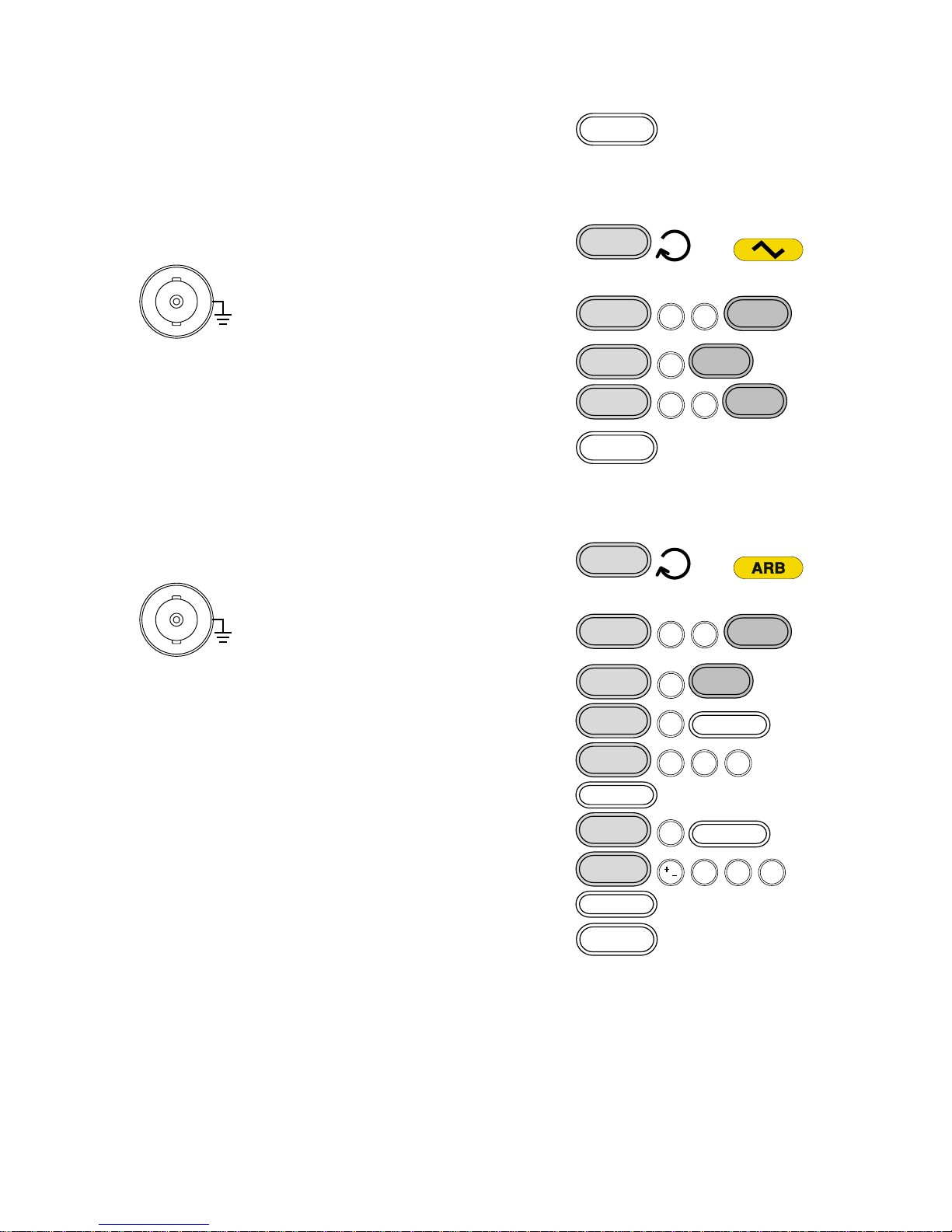
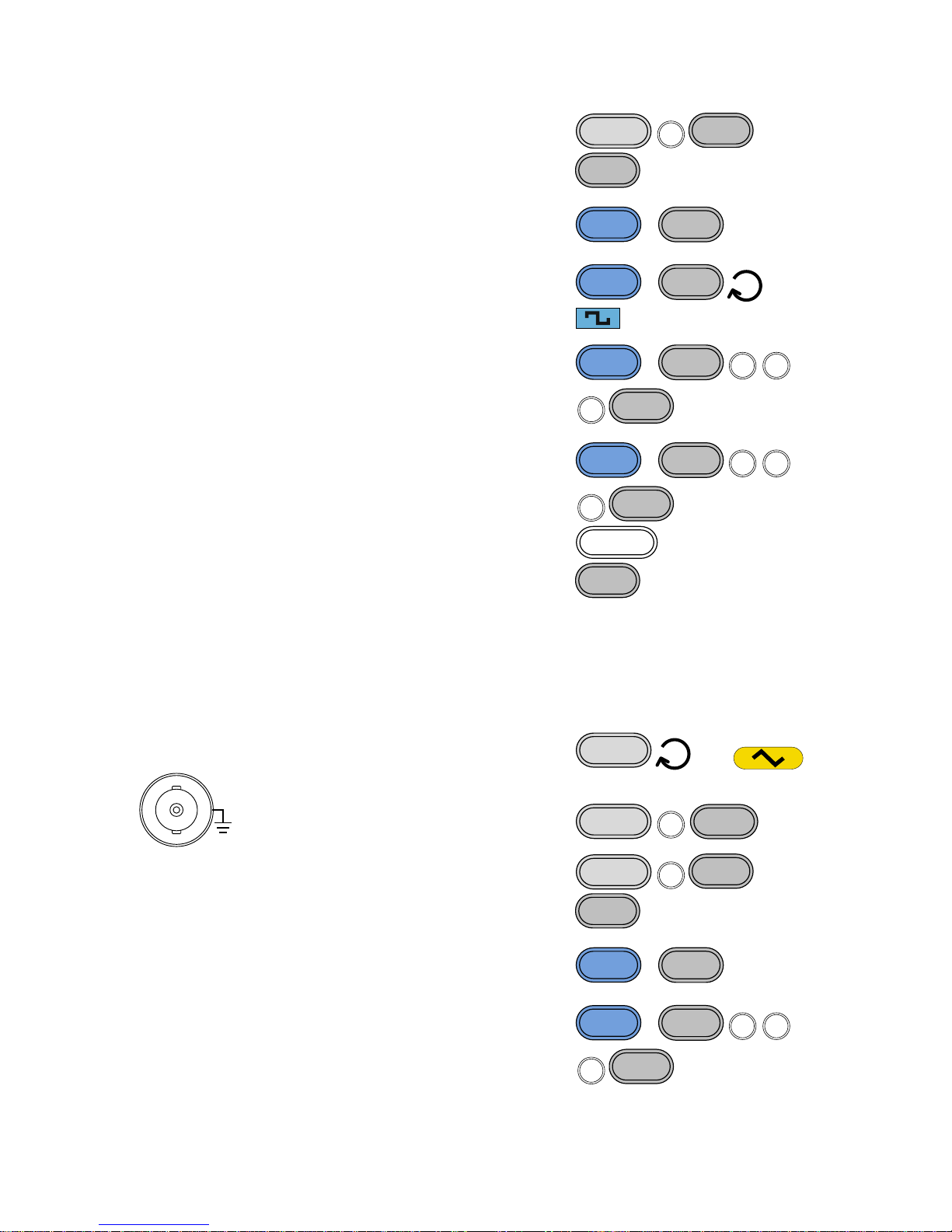
3-10. Frequency Shift Keying (FSK) Modulation (FGX-2112 )
Frequency Shift Keying Modulation is used to shift the frequency output of the
function generator between two preset frequencies (carrier frequency, hop
frequency). The frequency at which the carrier and hop frequency shift is
determined by the rate setting or the voltage level from the Trigger input port
on the rear panel.
FSK modulation is only applicable to the FGX-2112.
Hop Frequency
Carrier Frequency

35
3-10-1. Selecting FSK Modulation
Panel Operation
1. Press the FSK key.
FSK
2. The modulation, sweep and counter menu display
will appear. The FSK icon indicates that the FSK
function is active.
Example:
FSK activated
Note
FSK modulation can be deactivated by pressing the FSK
key again.
3-10-2. FSK Carrier Waveform
Background
The FUNC key selects the FSK carrier waveform. Sine,
square or ramp waveforms can be used as the carrier.
The default waveform is set to sine. Noise and ARB
cannot be used as a carrier wave.
Selecting the
Carrier
1. Press the FUNC key
repeatedly to select a
carrier waveform (Sine,
Square, Ramp).
FUNC
→
Range
FSK Carrier
Shape
sine, square, ramp
3-10-3. FSK Carrier Frequency
The maximum carrier frequency depends on the carrier shape. The default
carrier frequency for all carrier shapes is 1kHz. The voltage level of the
Trigger input port controls the output frequency when EXT is selected as the
source. When the Trigger input signal is logically low, the carrier frequency is
output and when the signal is logically high, the hop frequency is output.
Panel Operation
1. Press FREQ key.
FREQ

36
2. The FREQ icon will flash in the frequency display
area.
3. Use the arrow keys, scroll
wheel and Enter key to edit
the frequency.
→
Enter
Use the keypad and the
relevant unit key to enter a
new frequency.
0
/
321
4
7 859
6
→
Hz/Vpp
kHz/Vrms
MHz/dBm
Range
Sine
0.1Hz ~ 12MHz
Square
0.1Hz ~ 12MHz
Ramp
0.1Hz ~ 1MHz
Example:
FREQ = 1kHz
3-10-4. Setting the Carrier Amplitude
Panel Operation
1. Press AMPL key.
AMPL
2. The AMPL icon will flash in the secondary display
area.
3. Use the arrow keys, scroll
wheel and Enter key to edit
the amplitude.
→
Enter

37
Use the keypad and the
relevant unit key to enter a
new amplitude.
0
/
321
4
7 859
6
→
Hz/Vpp
kHz/Vrms
MHz/dBm
Range
No Load
2mVpp~20Vpp
50Ω Load
1mVpp~10Vpp
Example:
AMPL= 1Vpp
3-10-5. Setting the Hop Frequency
The default Hop frequency for all waveform shapes is 100 Hz. A square wave
with a duty cycle of 50% is used for the internal modulation waveform. The
voltage level of the Trigger input signal controls the output frequency when
EXT is selected. When the Trigger input signal is logically low the carrier
frequency is output and when the signal is logically high, the hop frequency is
output.
Panel Operation
1. Press the Shift + Hop key.
Shift
+
Hop
MHz/dBm
2. The Hop icon will flash in the frequency display
area.
3. Use the arrow keys,
scroll wheel and Enter
key to edit the hop
frequency.
→
Enter
Use the keypad and the
relevant unit key to enter
a hop frequency.
0
/
321
4
7 859
6
→
Hz/Vpp
kHz/Vrms
MHz/dBm
Range
Sine
0.1Hz ~ 12MHz
Square
0.1Hz ~ 12MHz

38
Ramp
0.1Hz ~ 1MHz
Default
100Hz
Example:
Hop = 100Hz
3-10-6. FSK Rate
FSK Rate function is used to determine the rate at which the output frequency
changes between the carrier and hop frequencies. The FSK Rate function
only applies to internal FSK sources.
Panel Operation
1. Press the Shift + Rate key.
Shift
+
Rate
FSK
2. The Rate icon will flash in the frequency display
area.
3. Use the arrow keys,
scroll wheel and Enter
key to edit the rate.
→
Enter
Use the keypad and the
relevant unit key to
enter a new rate.
0
/
321
4
7 859
6
→
Hz/Vpp
kHz/Vrms
Range
(Internal source)
2mHz ~ 20kHz
Default
100Hz
Example:
Rate= 1KHz

39
3-10-7. Setting the FSK Source
The FGX-2000 accepts internal and external FSK sources, with internal as the
default source. When the FSK source is set to internal, the FSK rate is
configured using the FSK Rate function. When an external source is selected
the FSK rate is equal to the frequency of the Trigger input signal on the rear
panel. When the input signal is logically low the carrier frequency is output
and when the signal is logically high, the hop frequency is output.
Panel Operation
1. Press the Shift + INT/EXT
key to select the modulation
source.
Shift
+
INT/EXT
kHz/Vrms
→
2. The FSK source will be displayed at the bottom of
the screen.
Range
Source
INT, EXT
Connection
(EXT source
only)
For external sources, connect the
FSK rate source signal to the
Trigger input port on the rear
panel.
OUTPUT INPUT
MOD Counter
Trigger MOD
Example:
Source = EXT
Example:
External trigger
input signal
FSK output
Trigger input
signal
0V

40
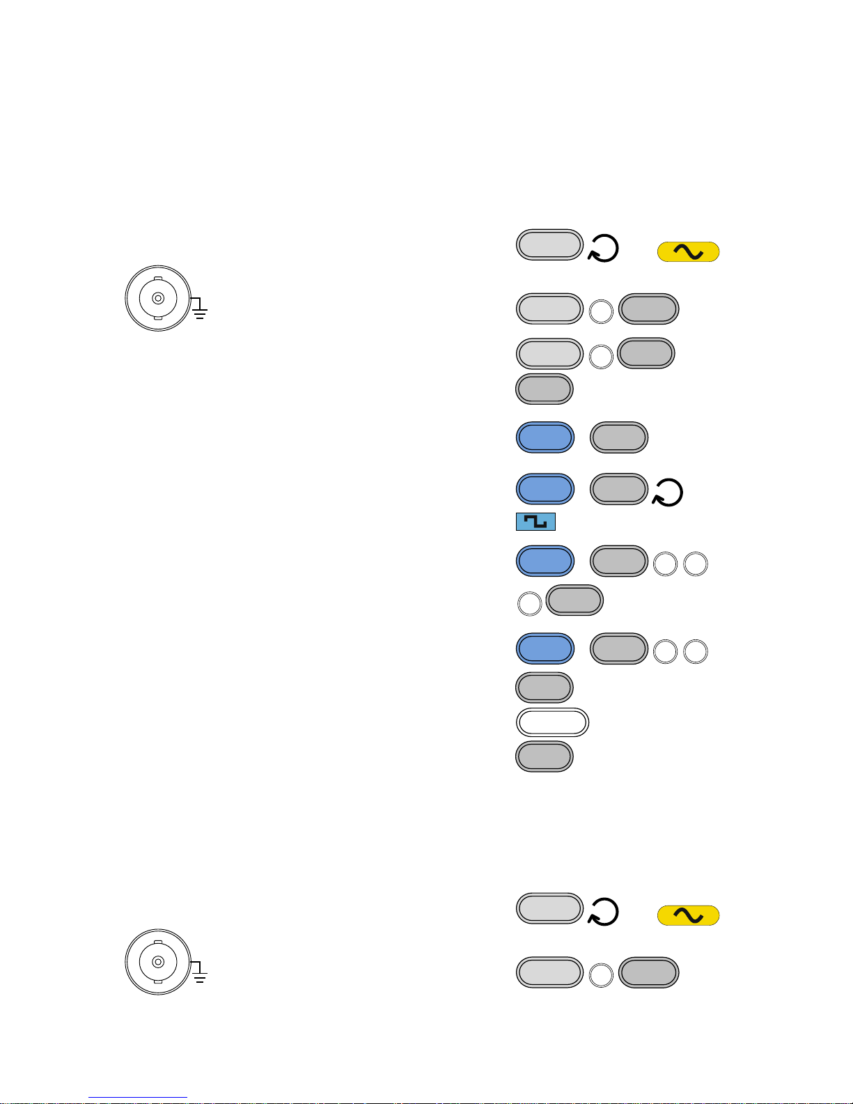
3-11. Frequency Sweep (FGX-2112 )
The function generator can perform a sweep for sine, square or ramp
waveforms, but not noise, and ARB. In Sweep mode, the function generator
will sweep from a start frequency to a stop frequency over a number of
designated steps. If an external source is selected, the function generator can
be used to output a single sweep each time a TTL level pulse is received from
the Trigger input port. The step spacing of the sweep can be linear or
logarithmic. The function generator can also sweep up or sweep down in
frequency. The Sweep function only applies to the FGX-2112.
Sweep
3-11-1. Selecting Sweep
Panel Operation
1. Press the Sweep key.
Sweep
2. The modulation, sweep and counter menu display
will appear. The Sweep icon indicates that the
Sweep function is active.
Example:
Sweep activated
Note
Sweep modulation can be deactivated by pressing the
Sweep key again.

41
3-11-2. Setting Start and Stop Frequency
The start and stop frequencies define the upper and lower sweep limits. The
function generator will sweep from the start through to the stop frequency and
cycle back to the start frequency. The sweep is phase continuous over the full
sweep range.
Panel Operation
1. Pressing the Shift +
Start/Stop key will toggle
between the start and stop
frequencies. Select the
Start frequency icon.
Shift
+
Start/Stop
Sweep
→ Start
2. The Start icon will flash in the frequency display
area when selected.
3. Use the arrow
keys, scroll wheel
and Enter key to
edit the start
frequency.
→
Enter
Use the keypad
and the relevant
unit key to enter a
new start
frequency.
0
/
321
4
7 859
6
→
Hz/Vpp
kHz/Vrms
MHz/dBm
Range
Sine
0.1Hz ~ 12MHz
Square
0.1Hz ~ 12MHz
Ramp
0.1Hz ~ 1MHz
Default
Start: 100Hz, Stop: 1kHz
4. Repeat steps 1 to 3 for the Stop frequency.
Note
To sweep from a low to high frequency, set the Start
frequency < Stop frequency.
To sweep from a high to low frequency, set the Start
frequency > Stop frequency.
Example:
Start = 100Hz

42
Example:
Stop = 1kHz
3-11-3. Sweep Mode
Sweep mode is used to select between linear or logarithmic sweeping. Linear
sweeping is the default setting.
Panel Operation
1. Press the Shift + LIN/LOG
key to select linear (LINS)
or logarithmic (LOGS)
sweeps.
Shift
+
LIN/LOG
%
→
2. The LINS or LOGS icon will be displayed at the
bottom of the screen.
Example:
Sweep = LINS
3-11-4. Sweep Rate
The sweep rate is used to determine how long it takes to perform a sweep
from the start to stop frequencies. The function generator automatically
determines the number of discrete frequencies used in the scan depending on
the length of the scan.
Panel Operation
1. Press the Shift + Rate key.
Shift
+
Rate
FSK
2. The Rate icon will flash in the frequency display
area.

43
3. Use the arrow
keys, scroll wheel
and Enter key to
edit the rate.
→
Enter
Use the keypad
and the relevant
unit key to enter a
new rate.
0
/
321
4
7 859
6
→
Hz/Vpp
kHz/Vrms
Range
Sweep Rate
1kHz ~ 2mHz (1ms ~ 500s)
Default
100Hz
Example:
Rate= 100Hz
3-11-5. Setting the Sweep Source (Trigger)
With the source set to EXT, the function generator will sweep each time a
trigger signal is received. After a sweep output has completed, the function
generator waits for a trigger signal before starting the next sweep. The default
trigger source is internal.
Panel Operation
1. Press the Shift + INT/EXT
key to select the modulation
source.
Shift
+
INT/EXT
kHz/Vrms
→
2. The Trigger source will be displayed at the bottom
of the screen.
Range
Source
INT, EXT

44
Connection
(EXT source
only)
For external sources, connect the
Sweep trigger signal to the
Trigger input port on the rear
panel.
OUTPUT INPUT
MOD Counter
Trigger MOD
Example:
Source = EXT
Note
With an external source, a sweep is output each time a
trigger pulse (TTL) is received from the Trigger input port
on the rear panel.
The trigger frequency must be greater than the sweep
rate (sweep time) plus 125nS (trigger pulse width >
125nS).
Example:
External trigger
input signal
Sweep output
0V
Trigger input
signal
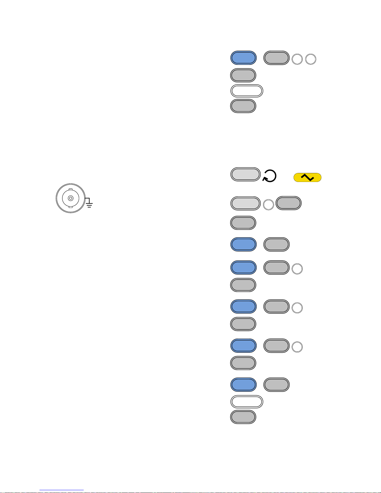
3-12. Creating an Arbitrary Waveform
Both the FGX-2000 has a simple arbitrary waveform editing function. The
ARB function is able to create waveforms with a 20MHz sampling rate, 4k
data points with vertical range of ±511points.
Selecting the
Carrier Shape
1. Press the FUNC key
repeatedly to select the
ARB function.
FUNC
→
2. Press the Point key.
Point
3. Point will flash in the secondary display area.

45
4. Use the scroll wheel or
keypad to choose a point
number.
or
0
/
321
4
7 859
6
Use the Enter key to
confirm the point number.
Enter
Range
Point:
0 ~ 4096
5. Press the Value key.
Point
6. Value will flash in the secondary display area.
7. Use the scroll wheel or
keypad to choose the
vertical value of the
selected point.
or
0
/
321
4
7 859
6
Use the Enter key to
confirm the point value.
Enter
Range
Value:
±511 (10-bit vertical resolution)
8. Repeat steps 2 to 7 for the remaining points of the
ARB waveform.
Note
The horizontal position of the points depends on the set
frequency. For example, if the set frequency is 1kHz
(period = 1ms), then each point will be located every
0.01ms (1ms/sample rate).
Example:
Point “0” is set to
+511.
Note
To save the ARB data, please see the Save/Recall
section on page.15

46
3-13. Using the Frequency Counter
3-13-1. Selecting the Frequency Counter Function
Connection
Connect the signal source to Counter input
port on the rear panel.
OUTPUT INPUT
MOD Counter
MOD
Trigger
Panel Operation
1. Press the Count key.
Gate
Count
2. The current gate time and the Count icon will
appear in the display when the counter function is
active.
The input frequency will be shown in the frequency
display area.
Example: input
frequency of
1kHz
3-13-2. Selecting the Gate Time
Panel Operation
1. Ensure the Count function is
active.
Page 46
2. Press the Shift + Gate key
repeatedly to select the desired
gate time.
Shift
+
Gate
Count
Range
Gate time
0.01s, 0.1s, 1s, 10s
3. The current gate time is displayed in the counter
settings area of the display.

47
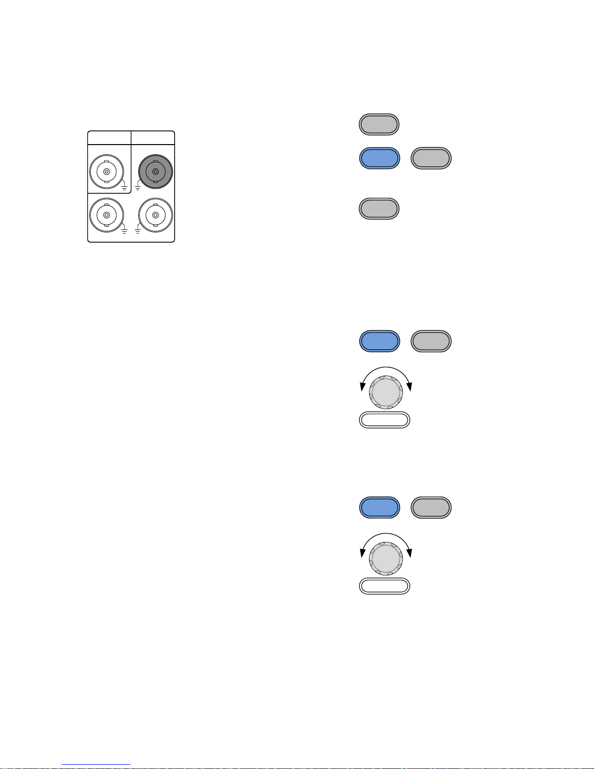
3-14. Using the SYNC Output Port
3-14-1. Connecting the SYNC Output Port
Background
The SYNC output port is used as a synchronization
signal for function outputs. All the output signals apart
from the noise output function have a synchronization
signal.
Connection
Connect a BNC cable from the
SYNC output port on the front
panel to the desired input device.
OUTPUT
50
W
SYNC
OUTPUT
Note
The SYNC signal is output even when the main output is
not output.
3-14-2. SYNC Output Signal
SYNC Output
For Sine Wave
SYNC output: TTL square waveform with a 50% duty
cycle. The SYNC output is at a logically high level when
the sine output is positive.
Output diagram
Sine output
SYNC output
0V
0V
SYNC Output
For Square
Wave
SYNC output: TTL square waveform with a duty cycle
corresponding to the duty cycle of the output square
wave. The SYNC output is at a logically high level when
the square wave output is positive.
Output diagram
Square wave
output
SYNC output
0V
0V
SYNC Output
For Ramp Wave
SYNC output: TTL square waveform with a 50% duty
cycle. The SYNC output is at a logically high level when
the ramp output is positive.

48
Output diagram
Ramp wave
output
SYNC output
0V
0V
SYNC Output
For ARB Wave
SYNC output: A single TTL positive pulse at the start of
each ARB period (pulse width = 1/sample rate).
Output diagram
ARB output
SYNC output
0V
0V
SYNC Output
For AM
SYNC output: TTL square waveform with a 50% duty
cycle. The SYNC output is at a logically high level when
the modulated output is positive.
Output diagram
AM output
SYNC output
0V
0V
SYNC Output
For FM
SYNC output: TTL square waveform with a 50% duty
cycle. The SYNC output is at a logically high level when
the modulated output is positive (The SYNC output is
synchronized to the modulated output frequency).
Output diagram
FM output
SYNC output
0V
0V

49
SYNC Output
For FSK
SYNC output: TTL square waveform with a 50% duty
cycle. The SYNC output is at a logically high level when
the modulated output is positive (The SYNC output is
synchronized to the modulated output frequency).
Output diagram
FSK output
SYNC output
0V
0V
SYNC Output
For Sweep
SYNC output: TTL square waveform. The SYNC output
is at a logically high level when the sweep output is
positive (The SYNC output is synchronized to the sweep
output frequency).
Output diagram
Sweep output
SYNC output
0V
0V
3-15. Save and Recall State/ARB Waveform
The FGX-2000 has non-volatile memory to store instrument state and ARB
data. There are 10 memory locations numbered 0~19. Memory locations 0~9
saves/recalls the instrument state, memory locations 10~19 saves / recalls
ARB data. The instrument saves the following states: the selected function
(including ARB), frequency, amplitude, DC offset, duty cycle / symmetry, and
any of the modulation parameters.
Panel Operation
1. Press the Shift +
Save/Recall key to either
select Save (to save the
state) or Recall (to recall
the state).
Shift
+
Save/Recall
Hz/Vpp
→ Save
2. Save or Recall will be shown in the secondary
display area.

50
3. Use the scroll wheel or
keypad to choose the
save/recall number.
or
0
/
321
4
7 859
6
Use the Enter key to
save/recall the state.
Enter
Note
The instrument state can be saved to any 10 (0~9) of the
storage locations. ARB data can be saved to any 10
(10~19) instrument locations.
When a state is saved, it overwrites the previously saved
state in the same location. If ARB data is recalled, the
current state will be overwritten.
A memory location can only be recalled if it has been
previously saved.
Example:
Save State
Example:
Recall State

51
4. REMOTE INTERFACE
4-1. Selecting the USB Remote Interface
The FGX-2000 uses a USB interface for remote control. Connecting to USB
USB
configuration
PC side connector
Type A, host
FGX side connector
Type B, slave
Speed
Class
USB Driver
1.1/2.0 (full speed)
CDC Class
*.inf
Panel Operation
1. Connect the
Type B USB - USB-A cable from the PC to
the type B USB port on the rear panel.
2. When the PC asks for the USB driver, select inf file
included in the CD or download the driver from our
website, www.texio.co.jp
If there is no request of the driver by the PC, please
specify the inf file to update the device driver of
FGX at the "Other devices" in the Device Manager
of the PC.
3. The USB icon will appear when the USB connection
is active.
4-1-1. Remote control terminal connection
Terminal
application
Invoke the terminal application such as Hyper Terminal.
Make note of the COM port, baud rate, stop bit, data bit,
and parity accordingly from the Windows Device
Manager.To check the COM port settings, see the Device
Manager from Control Panel in the PC. For Windows.
Functionality
check
Run this query command via the terminal.
*idn?
This should return the Manufacturer, Model number,
Serial number, and Firmware version in the following
format.
TEXIO, FGX-2112, SN:XXXXXXXX,Vm.mm
Note
^j and ^m can be used as the terminal character when
using a terminal program.
PC Software
The proprietary PC software, downloadable from TEXIO
website, can be used to download waveforms.

52
4-2. Command Syntax
Compatible
standard
• IEEE488.2, 1992 (fully compatible)
• SCPI, 1994 (partially compatible)
Command Tree
The SCPI standard is an ASCII based standard that
defines the command syntax and structure for
programmable instruments.
Commands are based on a hierarchical tree structure.
Each command keyword is a node on the command tree
with the first keyword as the root node. Each sub node is
separated with a colon.
Shown below is a section of the SOURce[1] root node
and the APPLy/OUTPut and SINusoid/SQUare sub
nodes.
SOURce[1|2]
:OUTPut :APPLy
:SINusoid :SQUare
Root
node
2nd node
3rd node
Command types
Commands can be separated into three distinct types,
simple commands, compound commands and queries.
Simple
A single command with/without a
parameter
Example
*OPC
Compound
Two or more commands separated by a
colon (:) with/without a parameter
Example
SOURce:APPLy:SQUare
Query
A query is a simple or compound
command followed by a question mark
(?). A parameter (data) is returned. The
maximum or minimum value for a
parameter can also be queried where
applicable.
Example
SOURce1:FREQuency?
SOURce1:FREQuency? MIN

53
Command forms
Commands and queries have two different forms, long
and short. The command syntax is written with the short
form of the command in capitals and the remainder (long
form) in lower case.
SOURce1:DCOffset
long long
short short
The commands can be written in capitals or lower-case,
just so long as the short or long forms are complete. An
incomplete command will not be recognized.
Below are examples of correctly written commands:
LONG:
SOURce1:DCOffset
SOURCE1:DCOFFSET
source1:dcoffset
SHORT:
SOUR1:DCO
sour1:dco
Command
Format
SOURce1:DCOffset < offset>LF
1 32
4
1: command header
2: single space
3: parameter
4: message terminator
Square Brackets
[ ]
Commands that contain squares brackets indicate that
the contents are optional. The function of the command is
the same with or without the square bracketed items.
Brackets are not sent with the command.
For example, the frequency query below can use any of
the following 3 forms:
SOURce1:FREQuency? [MINimum|MAXimum]
SOURce1:FREQuency? MAXimum
SOURce1:FREQuency? MINimum
SOURce1:FREQuency?
Braces { }
Commands that contain braces indicate one item within
the braces must be chosen. Braces are not sent with the
command.
Angled Brackets
< >
Angle brackets are used to indicate that a value must be
specified for the parameter. See the parameter
description below for details. Angled brackets are not
sent with the command.
Bars |
Bars are used to separate multiple parameter choices in
the command format.
Parameters
Type
Description
Example
<Boolean>
Boolean logic
0, 1/ON,OFF

54
<NR1>
integers
0, 1, 2, 3
<NR2>
decimal numbers
0.1, 3.14, 8.5
<NR3>
floating point
4.5e-1, 8.25e+1
<NRf>
any of NR1, 2, 3
1, 1.5, 4.5e-1
<NRf+>
<Numeric>
NRf type with a
suffix including
MINimum,
MAXimum or
DEFault
parameters.
1, 1.5, 4.5e-1
MAX, MIN, DEF
<aard>
Arbitrary ASCII
characters.
<discrete>
Discrete ASCII
character
parameters
IMM, EXT, MAN
<frequency>
<peak
deviation in
Hz>
<rate in Hz>
NRf+ type
including
frequency unit
suffixes.
1 KHZ, 1.0 HZ, ΜHZ
<amplitude>
NRf+ type
including voltage
unit suffixs.
VPP, dBm, Vrms
<offset>
NRf+ type
including voltage
unit suffixes.
V
<seconds>
NRf+ type
including time unit
suffixes.
nS, uS, mS, S
<percent>
<depth in
percent>
NRf type
N/A
Message
terminators
LF CR
line feed code (new line) and carriage
return.
LF
line feed code (new line)
Note
^j or ^m should be used when using a terminal program.
Command
Separators
Space
A space is used to separate a parameter
from a keyword/command header.
Colon (:)
A colon is used to separate keywords on
each node.

55
Semicolon (;)
A semicolon can be used to combine
commands from different node levels.
For example:
SOURce1:PWM:SOURce?
SOURce:PULSe:WIDTh?
→SOURce1:PWM:SOURce?;SOURce:
PULSe:WIDTh?
Comma (,)
When a command uses multiple
parameters, a comma is used to
separate the parameters.
For example:
SOURce:APPLy:SQUare 10KHZ,2.0
VPP,-1VDC

56
4-3. Command List
4-3-1. System Commands ................................................................................... 57
4-3-2. Status Register Commands ....................................................................... 57
4-3-2-1. *CLS ....................................................................................................... 57
4-3-3. APPLy Commands ..................................................................................... 57
4-3-3-1. SOURce[1]:APPLy:SINusoid .................................................................. 59
4-3-3-2. SOURce[1]:APPLy:SQUare ................................................................... 59
4-3-3-3. SOURce[1]:APPLy:RAMP ...................................................................... 59
4-3-3-4. SOURce[1]:APPLy:NOISe ...................................................................... 60
4-3-3-5. SOURce[1]:APPLy:USER ...................................................................... 60
4-3-3-6. SOURce[1]:APPLy? ............................................................................... 61
4-3-4. Output Commands .................................................................................... 61
4-3-4-1. SOURce[1]:FUNCtion ............................................................................ 61
4-3-4-2. SOURce[1]:FREQuency ......................................................................... 62
4-3-4-3. SOURce[1]:AMPLitude ........................................................................... 63
4-3-4-4. SOURce[1]:DCOffset.............................................................................. 64
4-3-4-5. SOURce[1]:SQUare:DCYCle ................................................................. 64
4-3-4-6. SOURce[1]:RAMP:SYMMetry ................................................................ 65
4-3-4-7. OUTPut .................................................................................................. 66
4-3-4-8. SOURce[1]:OUTPut:LOAD..................................................................... 66
4-3-4-9. SOURce[1]:VOLTage:UNIT .................................................................... 66
4-3-5. Amplitude Modulation (AM) Commands .................................................... 67
4-3-5-1. SOURce[1]:AM:STATe ............................................................................ 68
4-3-5-2. SOURce[1]:AM:SOURce ........................................................................ 68
4-3-5-5. SOURce[1]:AM:DEPTh .......................................................................... 69
4-3-6. Frequency Modulation (FM) Commands ................................................... 70
4-3-6-1. SOURce[1]:FM:STATe ............................................................................ 71
4-3-6-2. SOURce[1]:FM:SOURce ........................................................................ 71
4-3-6-5. SOURce[1]:FM:DEViation ...................................................................... 72
4-3-7. Frequency-Shift Keying (FSK) Commands ................................................ 73
4-3-7-1. SOURce[1]:FSKey:STATe ...................................................................... 74
4-3-7-2. SOURce[1]:FSKey:SOURce .................................................................. 74
4-3-7-3. SOURce[1]:FSKey:FREQuency ............................................................. 75
4-3-8. Frequency Sweep Commands .................................................................. 76
4-3-8-1. SOURce[1]:SWEep:STATe ..................................................................... 76
4-3-8-2. SOURce[1]:FREQuency:STARt ............................................................. 77
4-3-8-3. SOURce[1]:FREQuency:STOP .............................................................. 77
4-3-8-4. SOURce[1]:SWEep:SPACing ................................................................. 78
4-3-8-5. SOURce[1]:SWEep:RATE ...................................................................... 78
4-3-8-6. SOURce[1]:SWEep:SOURce ................................................................. 78
4-3-9. Frequency Counter Commands................................................................. 79
4-3-9-1. COUNter:GATe ....................................................................................... 79
4-3-9-2. COUNter:STATe ..................................................................................... 79
4-3-9-3. COUNter:VALue? ................................................................................... 80
4-3-10. Arbitrary Waveform Commands ............................................................... 80

57
4-3-10-1. SOURce[1]:FUNCtion USER ................................................................ 81
4-3-10-2. DATA:DAC ............................................................................................ 81
4-3-11. Save and Recall Commands ................................................................... 82
4-3-11-1. *SAV ..................................................................................................... 82
4-3-11-2. *RCL ..................................................................................................... 82
4-3-1. System Commands
4-3-1-1. *IDN?
Query
Description
Returns the function generator manufacturer, model
number, serial number and firmware version number in the
following format:
TEXIO,FGX-2005,SN:XXXXXXXX,Vm.mm
Query Syntax
IDN?
Return
parameter
<string>
Query Example
*IDN?
> TEXIO,FGX-2005,SN:XXXXXXXX,Vm.mm
Returns the identification of the function generator.
4-3-1-2. *RST
Set
Description
Reset the function generator to its factory default state.
Note
Note the *RST command will not delete instrument save
states/ARB waveforms in memory.
Syntax
*RST
4-3-2. Status Register Commands
4-3-2-1. *CLS
Set
Description
The *CLS command clears all the event registers, the error
queue and cancels an *OPC command.
Syntax
*CLS
4-3-3. APPLy Commands
The APPLy command has 5 different types of outputs (Sine, Square, Ramp,
Noise, User(ARB)). The APPLy command is the quickest, easiest way to
output waveforms remotely. Frequency, amplitude and offset can be
specified for each function.
As only basic parameters can be set with the APPLy command, other
parameters, such as duty and symmetry use the instrument default values.
The APPLy command will set the trigger source to immediate and disable
modulation and sweep modes, if active. The command also turns on the
output command SOURce[1]:OUTP ON.
As the frequency, amplitude and offset parameters are in nested square

58
brackets, the amplitude can only be specified if the frequency has been
specified and the offset can only be specified if the amplitude has been set.
See the syntax below for the example:
SOURce1:APPLy:<function> [<frequency> [,<amplitude> [,<offset>] ]]
Output
Frequency
For the output frequency, MINimum, MAXimum and
DEFault can be used instead of specifying a frequency.
The default frequency for all functions is set to 1 kHz.
The maximum and minimum frequency depends on the
function used and the model of the frequency generator.
If a frequency output that is out of range is specified, the
max/min frequency will be used instead. A “-222” error will
be generated from the remote terminal.
Function
Min frequency
Max frequency
Sine
0.1Hz
12MHz*
Square
0.1Hz
12MHz*
Ramp
0.1Hz
1MHz
Noise
Not applicable
Not applicable
User (ARB)
0.1Hz
12MHz
*The FGX-2005 is limited to 5MHz.
Output
Amplitude
When setting the amplitude, MINimum, MAXimum and
DEFault can be used instead of specifying an amplitude.
The range depends on the function being used. The
default amplitude for all functions is 100 mVpp (into 50Ω).
Vrms, dBm or Vpp units can be used to specify the output
units to use with the current command. Note, however, that
the VOLT:UNIT command can be used to set the default
units (Vrms, dBm, Vpp) for all commands. This will be
applicable to the APPLy command when no unit is
specified. The unit default is set to Vpp.
The output amplitude can be affected by the function and
unit chosen. Vpp and Vrms or dBm values may have
different maximum values due to differences such as crest
factor. For example, a 5Vrms square wave will be adjusted
to 3.536 Vrms for a sine wave.
DC Offset
voltage
The offset parameter can be set to MINimum, MAXimum or
DEFault instead of a specified DC offset value. The default
DC offset is 0 volts.
The maximum and minimum DC offset is limited by the

59
output amplitude as shown below.
|Voffset| < Vmax – Vpp/2
This means that the magnitude of the DC offset is
determined by the output amplitude.
If the specified DC offset is out of range, the
maximum/minimum offset will be set instead. A “-222” error
will be generated from the remote terminal.
4-3-3-1. SOURce[1]:APPLy:SINusoid
Set
Description
Outputs a sine wave when the command has executed.
Frequency, amplitude and offset can also be set.
Syntax
SOURce[1]:APPLy:SINusoid [<frequency> [,<amplitude>
[,<offset>] ]]
Parameter
<frequency>
0.1Hz~12MHz*
<amplitude>
1mV~10Vpp (50Ω)
<offset>
-5V ~ +5V (50Ω)
*FGX-2005 limited to 5MHz.
Example
SOURce1:APPL:SIN MAX, 3.0, -2.5
Outputs a 3Vpp sine wave at 12MHz (max frequency) with
a -2.5V offset.
4-3-3-2. SOURce[1]:APPLy:SQUare
Set
Description
Outputs a square wave when the command has executed.
Frequency, amplitude and offset can also be set. The duty
cycle is fixed to 50%.
Syntax
SOURce[1]:APPLy:SQUare [<frequency> [,<amplitude>
[,<offset>] ]]
Parameter
<frequency>
0.1Hz ~ 12MHz*
<amplitude>
1mV~10V (50Ω)
<offset>
-5V ~ +5V (50Ω)
*FGX-2005 limited to 5MHz.
Example
SOURce1:APPL:SQU MAX, DEF, DEF
Outputs a 100mVpp (DEF) square wave at 12MHz with 0
offset (DEF).
4-3-3-3. SOURce[1]:APPLy:RAMP
Set
Description
Outputs a ramp wave when the command has executed.
Frequency, amplitude and offset can also be set. The
symmetry is fixed to 100%.

60
Syntax
SOURce[1]:APPLy:RAMP [<frequency> [,<amplitude>
[,<offset>] ]]
Parameter
<frequency>
0.1Hz~1MHz
<amplitude>
1mV~10V (50Ω)
<offset>
-5V ~ +5V (50Ω)
Example
SOUR1:APPL:RAMP 2KHZ,MAX,MAX
Sets the frequency to 2kHz and sets the amplitude and
offset to the maximum.
4-3-3-4. SOURce[1]:APPLy:NOISe
Set
Description
Outputs Gaussian noise with a 20 MHz bandwidth.
Amplitude and offset can also be set.
Note
The Frequency parameter is not used with the noise
function; however a value (or DEFault) must still be
specified. The frequency is remembered for the next
function used.
Syntax
SOURce[1]:APPLy:NOISe [<frequency|DEFault>
[,<amplitude> [,<offset>] ]]
Parameter
<frequency>
0.1Hz~12MHz*
<amplitude>
1mV~10V (50Ω)
<offset>
-5V ~ +5V (50Ω)
*FGX-2005 limited to 5MHz.
Example
SOURce1:APPL:NOIS DEF, 5.0, 2.0
Sets the amplitude to 5 volts with an offset of 2 volts.
4-3-3-5. SOURce[1]:APPLy:USER
Set
Description
Outputs an arbitrary waveform that is specified from the
FUNC:USER command.
Note
Frequency and amplitude values are not used with this
function; however a value (or DEFault) must be specified.
The values are remembered for the next function used.
Syntax
SOURce[1]:APPLy:USER [<frequency> [,<amplitude>
[,<offset>] ]]
Parameter
<frequency>
0.1Hz~10MHz
<amplitude>
1mV~10V (50Ω)
<offset>
-5V ~ +5V (50Ω)
Example
SOUR1:APPL:USER
Outputs the ARB waveform specified in the FUNC:USER
command.

61
4-3-3-6. SOURce[1]:APPLy?
Query
Description
Outputs a string with the current settings.
Note
The returned string can be passed back, when appended
to the APPLy Command. This is intended to be used to
return the function generator to a known state.
I.e., SOURce[1]:APPL:<passed back string>
Query Syntax
SOURce[1]:APPLy?
Return
Parameter
<string>
Function(<NRf>), frequency(<NRf>),
amplitude(<NRf>),offset(<NRf>)
Query Example
SOUR1:APPL?
>”SIN +5.0000000000000E+03,+3.0000E+00,-2.50E+00”
Returns a string with the current function and parameters,
Sine, 5kHz, 3Vpp, -2.5V offset.
4-3-4. Output Commands
Unlike the APPLy commands, the Output commands are low level commands
to program the function generator.
This section describes the low-level commands used to program the function
generator. Even though the APPLy command is the easiest way to program
the function generator, it lacks the ability to change individual parameters.
The Output commands on the other hand can be used to set individual
parameters, or those parameters that cannot be programmed with the APPLy
command.
4-3-4-1. SOURce[1]:FUNCtion
Set
Query
Description
The FUNCtion command selects and outputs the selected
output function. The User parameter outputs an arbitrary
waveform previously set by the SOURce[1]:FUNC:USER
command.
The previously set frequency, amplitude and offset values
are used automatically.
Note
If the function mode is changed and the current frequency
setting is not supported by the new mode, the frequency
setting will be altered to the next highest value.
Vpp and Vrms or dBm amplitude values may have different
maximum values due to differences such as crest factor.
For example, if a 5Vrms square wave is changed to a
sinewave, then the Vrms value is automatically adjusted to
3.536Vrms.

62
The modulation and sweep modes can only be used with
some of the basic waveforms. If a mode is not supported,
the conflicting mode will be disabled. See the table below.
Sine
Square
Ramp
Noise
ARB
AM
✓
✓
✓
FM
✓
✓
✓
FSK
✓
✓
✓
SWEEP
✓
✓
✓
Syntax
SOURce[1]:FUNCtion {SINusoid|SQUare|RAMP |NOISe
|USER}
Example
SOUR1:FUNC SIN
Sets the output as a sine function.
Query Syntax
SOURce[1]:FUNCtion?
Return
Parameter
SIN, SQU, RAMP, NOIS,
USER
Returns the current output type.
Query Example
SOUR1:FUNC?
>SIN
Current output is sine.
4-3-4-2. SOURce[1]:FREQuency
Set
Query
Description
Sets the output frequency for the SOURce[1]:FUNCtion
command. The query command returns the current
frequency setting.
Note
The maximum and minimum frequency depends on the
function mode.
Sine, Square
0.1Hz~12MHz*
Ramp
0.1Hz ~ 1MHz
Noise
Not applicable
User
0.1Hz~12MHz*
*FGX-2005 limited to 5MHz.
If the function mode is changed and the current frequency
setting is not supported by the new mode, the frequency
setting will be altered to the next highest value.
The duty cycle of square waveforms depends on the
frequency settings:
1% to 99% (frequency < 100KHz)
20% to 80% (100KHz < frequency < 5 MHz)
40% to 60% (5 MHz < frequency < 10 MHz)
50% (frequency > 10 MHz)

63
If the frequency is changed and the set duty cycle cannot
support the new frequency, the highest duty cycle available
at that frequency will be used. A “-221” error will be
generated from the remote terminal.
Syntax
SOURce[1]:FREQuency
{<frequency>|MINimum|MAXimum}
Example
SOUR1:FREQ MAX
Sets the frequency to the maximum for the current mode.
Query Syntax
SOURce[1]:FREQuency?
Return
Parameter
<NR3>
Returns the frequency for the current mode.
Query Example
SOUR1:FREQ? MAX
>+1.0000000000000E+03
The maximum frequency that can be set for the current
function is 1MHz.
4-3-4-3. SOURce[1]:AMPLitude
Set
Query
Description
Sets the output amplitude for the SOURce[1]:FUNCtion
command. The query command returns the current
amplitude settings.
Note
The maximum and minimum amplitude depends on the
output termination. The default amplitude for all functions is
100 mVpp (50Ω).
The offset and amplitude are related by the following
equation.
|Voffset| < Vmax – Vpp/2
The output amplitude can be affected by the function and
unit chosen. Vpp and Vrms or dBm values may have
different maximum values due to differences such as crest
factor. For example, a 5Vrms square wave will be adjusted
to 3.536 Vrms for a sine wave.
The amplitude units can be explicitly used each time the
SOURce[1]:AMPLitude command is used. Alternatively, the
VOLT:UNIT command can be used to set the amplitude
units for all commands.
Syntax
SOURce[1]:AMPLitude {< amplitude>
|MINimum|MAXimum}
Example
SOUR1:AMPL MAX
Sets the amplitude to the maximum for the current mode.
Query Syntax
SOURce[1]:AMPLitude? {MINimum|MAXimum}
Return
Parameter
<NR3>
Returns the amplitude for the current mode.

64
Query Example
SOUR1:AMPL? MAX
>+5.0000E+00
The maximum amplitude that can be set for the current
function is 5 volts.
4-3-4-4. SOURce[1]:DCOffset
Set
Query
Description
Sets or queries the DC offset for the current mode.
Note
The offset parameter can be set to MINimum or MAXimum.
The default offset is 0 volts. The offset is limited by the
output amplitude as shown below.
|Voffset| < Vmax – Vpp/2
If the output specified is out of range, the maximum offset
will be set.
The maximum offset is ±5V into 50Ω).
Syntax
SOURce[1]:DCOffset {< offset> |MINimum|MAXimum}
Example
SOUR1:DCO MAX
Sets the offset to the maximum for the current mode.
Query Syntax
SOURce[1]:DCOffset? {MINimum|MAXimum}
Return
Parameter
<NR3>
Returns the offset for the current mode.
Query Example
SOUR1:DCO?
>+3.0000E+00
The offset for the current mode is set to +3 volts.
4-3-4-5. SOURce[1]:SQUare:DCYCle
Set
Query
Description
Sets or queries the duty cycle for square waves only. The
setting is remembered if the function mode is changed. The
default duty cycle is 50%.
Note
The duty cycle of square waveforms depend on the
frequency settings.
1% to 99% (frequency < 100KHz)
20% to 80% (100KHz < frequency < 5 MHz)
40% to 60% (5 MHz < frequency < 10 MHz)
50% (frequency > 10 MHz
If the frequency is changed and the set duty cycle cannot
support the new frequency, the highest duty cycle available
at that frequency will be used. A “-221” error will be
generated from the remote terminal.

65
For square waveforms, the APPLy command and AM/FM
modulation modes ignore the duty cycle settings.
Syntax
SOURce[1]:SQUare:DCYCle {< percent>
|MINimum|MAXimum}
Example
SOUR1:SQU:DCYC MAX
Sets the duty cycle to the highest possible for the current
frequency.
Query Syntax
SOURce[1]:SQUare:DCYCle? {MINimum|MAXimum}
Return
Parameter
<NR3>
Returns the duty cycle as a percentage.
Query Example
SOUR1:SQU:DCYC?
>+5.00E+01
The duty cycle is set 50%.
4-3-4-6. SOURce[1]:RAMP:SYMMetry
Set
Query
Description
Sets or queries the symmetry for ramp waves only. The
setting is remembered if the function mode is changed. The
default symmetry is 100%.
0% symmetry is a ramp waveform with a negative going
transition. 100% symmetry is a ramp waveform with a
positive going transition.
0% 50% 100%
Note
For ramp waveforms, the Apply command and AM/FM
modulation modes ignore the current symmetry settings.
Syntax
SOURce[1]:RAMP:SYMMetry {< percent>
|MINimum|MAXimum}
Example
SOUR[1]:RAMP:SYMM MAX
Sets the symmetry to the 100%.
Query Syntax
SOURce[1]:RAMP:SYMMetry? {MINimum|MAXimum}
Return
Parameter
<NR3>
Returns the symmetry as a percentage.
Query Example
SOUR1:RAMP:SYMMetry?
>+1.0000E+02
The symmetry is set as 100%.

66
4-3-4-7. OUTPut
Set
Query
Description
Enables/Disables or queries the front panel output. The
default is set to off.
Syntax
OUTPut {OFF|ON}
Example
OUTP ON
Turns the output on.
Query Syntax
OUTPut?
Return
Parameter
1 0 ON
OFF
Query Example
OUTP?
>1
The output is currently on.
4-3-4-8. SOURce[1]:OUTPut:LOAD
Set
Query
Description
Sets or queries the output termination. Two impedance settings
can be chosen, DEFault (50Ω) and INFinity (high impedance).
Syntax
SOURce[1]:OUTPut:LOAD{DEF|INF}
Example
SOUR:OUTP:LOAD DEF
Sets the channel 1 output termination to 50Ω.
Query Syntax
SOURce[1]:OUTPut:LOAD?
Return Parameter
DEF
Default
INF
INFinity
Example
SOUR:OUTP:LOAD?
>DEF
The output termination for channel 1 is set to 50Ω.
4-3-4-9. SOURce[1]:VOLTage:UNIT
Set
Query
Description
Sets or queries the output amplitude units. There are three
types of units: VPP, VRMS and DBM. The
SOURce[1]:VOLTage:UNIT command does not set the
offset units.
Note
The units set with the VOLTage:UNIT command will be used
as the default unit for all amplitude units unless a different

67
unit is specifically used for a command, such as those used
with the APPLy commands.
Syntax
SOURce[1]:VOLTage:UNIT {VPP|VRMS|DBM}
Example
SOUR1:VOLT:UNIT VPP
Sets the amplitude units to Vpp.
Query Syntax
SOURce[1]:VOLTage:UNIT?
Return
Parameter
VPP
Vpp
VRMS
Vrms
DBM
dBm
Query Example
SOUR1:VOLT:UNIT?
>VPP
The amplitude units are set to Vpp.
4-3-5. Amplitude Modulation (AM) Commands
To successfully create an AM waveform, the following commands must be
executed in order.
Enable AM
Modulation
Configure
Carrier
Select
Modulation
Source
Select Shape
Set Modulating
Frequency
Set Modulation
Depth
1. Turn on AM modulation using the
SOURce[1]:AM:STAT ON command
2. Use the APPLy command to select a carrier
waveform. Alternatively the equivalent FUNC, FREQ,
AMPL, and DCO commands can be used to create a
carrier waveform with a designated frequency,
amplitude and offset. Sine, square or ramp can be
used as the carrier wave.
3. Select an internal or external modulation source
using the SOURce[1]:AM:SOUR command.
4. Use the SOURce[1]:AM:INT:FUNC command to
select a Sine, Square or Ramp modulating waveform.
For internal sources only.
5. Set the modulating frequency using the
SOURce[1]:AM:INT:FREQ command. For internal
sources only.
6. Set the modulation depth using the
SOURce[1]:AM:DEPT command.

68
4-3-5-1. SOURce[1]:AM:STATe
Set
Query
Description
Sets or disables AM modulation. By default AM modulation
is disabled. AM modulation must be enabled before setting
other parameters.
Note
As only one mode is allowed at any one time, other
modulation modes (inc. Sweep/FSK) will be disabled when
AM modulation is enabled.
Syntax
SOURce[1]:AM:STATe {OFF|ON}
Example
SOUR1:AM:STAT ON
Enables AM modulation.
Query Syntax
SOURce[1]:AM:STATe?
Return
Parameter
0
Disabled (OFF)
1
Enabled (ON)
Query Example
SOUR1:AM:STAT?
>1
AM modulation mode is currently enabled.
4-3-5-2. SOURce[1]:AM:SOURce
Set
Query
Description
Sets or queries the modulation source as internal or
external. Internal is the default modulation source.
Note
If an external modulation source is selected, modulation
depth is limited to ± 5V from the MOD input port on the rear
panel. For example, if modulation depth is set to 100%,
then the maximum amplitude is +5V, and the minimum
amplitude is -5V.
Syntax
SOURce[1]:AM:SOURce {INTernal|EXTernal}
Example
SOUR1:AM:SOUR EXT
Sets the modulation source to external.
Query Syntax
SOURce[1]:AM:SOURce?
Return
Parameter
INT
Internal
EXT
External
Query Example
SOUR1:AM:SOUR?
>INT
The modulation source is set to internal.

69
4-3-5-3. SOURce[1]:AM:INTernal:FUNCtion
Set
Query
Description
Sets the shape of the modulating waveform from sine,
square or ramp. The default shape is sine.
Note
Square waveforms have a 50% duty cycle. Ramp
waveforms have a symmetry of 100%.
Syntax
SOURce[1]:AM:INTernal:FUNCtion {SINusoid|SQUare|
RAMP }
Example
SOUR1:AM:INT:FUNC SIN
Sets the AM modulating wave shape to sine.
Query Syntax
SOURce[1]:AM:INTernal:FUNCtion?
Return
Parameter
SIN
Sine
SQU
Square
RAMP
Ramp
Query Example
SOUR1:AM:INT:FUNC?
>SIN
The shape for the modulating waveform is Sine.
4-3-5-4. SOURce[1]:AM:INTernal:FREQuency
Set
Query
Description
Sets the frequency of the internal modulating waveform
only. The default frequency is 100Hz.
Syntax
SOURce[1]:AM:INTernal:FREQuency
{<frequency>|MINimum|MAXimum}
Parameter
<frequency>
2 mHz~ 20 kHz
Example
SOUR1:AM:INT:FREQ +1.0000E+02
Sets the modulating frequency to 100Hz.
Query Syntax
SOURce[1]:AM:INTernal:FREQuency?
[MINimum|MAXimum]
Return
Parameter
<NR3>
Returns the frequency in Hz.
Query Example
SOUR1:AM:INT:FREQ? MIN
>+1.0000E+02
Returns the minimum frequency allowed.
4-3-5-5. SOURce[1]:AM:DEPTh
Set
Query
Description
Sets or queries the modulation depth for internal sources
only. The default is 100%.

70
Note
The function generator will not output more than ±5V,
regardless of the modulation depth.
The modulation depth of an external source is controlled
using the ±5V MOD input port on the rear panel, and not
the SOURce[1]:AM:DEPTh command.
Syntax
SOURce[1]:AM:DEPTh {<depth in percent>
|MINimum|MAXimum}
Parameter
<depth in percent>
0~120%
Example
SOUR1:AM:DEPT 50
Sets the modulation depth to 50%.
Query Syntax
SOURce[1]:AM:DEPTh? [MINimum|MAXimum]
Return
Parameter
<NR3>
Return the modulation depth as a
percentage.
Query Example
SOUR1:AM:DEPT?
>+1.0000E+02
The modulation depth is 100%.
4-3-6. Frequency Modulation (FM) Commands
The following is an overview of the steps required to generate an FM
waveform.
Enable FM
Modulation
Configure
Carrier
1. Turn on FM modulation using the SOURce[1]:
FM:STAT ON command.
2. Use the APPLy command to select a carrier
waveform. Alternatively, the FUNC, FREQ, AMPL,
and DCO commands can be used to create a carrier
waveform with a designated frequency, amplitude
and offset.
Select
Modulation
Source
Select shape
Set Modulating
Frequency
Set Peak
Frequency
Deviation
3. Select an internal or external modulation source
using the SOURce[1]:FM:SOUR command.
4. Use the SOURce[1]:FM:INT:FUNC command to
select a sine, square or ramp modulating waveform.
For internal sources only.
5. Set the modulating frequency using the SOURce[1]:
FM:INT:FREQ command. For internal sources only.
6. Use the SOURce[1]:FM:DEV command to set the
frequency deviation.

71
4-3-6-1. SOURce[1]:FM:STATe
Set
Query
Description
Sets or disables FM modulation. By default FM modulation
is disabled. FM modulation must be enabled before setting
other parameters.
Note
As only one mode is allowed at any one time, other modes
(AM, FSK, Sweep etc.) will be disabled when FM
modulation is enabled.
Syntax
SOUR[1]:FM:STATe {OFF|ON}
Example
SOUR1:FM:STAT ON
Enables FM modulation.
Query Syntax
SOURce[1]:FM:STATe?
Return
Parameter
0
Disabled (OFF)
1
Enabled (ON)
Query Example
SOUR1:FM:STAT?
>1
FM modulation mode is currently enabled.
4-3-6-2. SOURce[1]:FM:SOURce
Set
Query
Description
Sets or queries the modulation source as internal or
external. Internal is the default modulation source.
Note
If an external modulation source is selected, the frequency
deviation is limited to ± 5V from the MOD input port on the
rear panel. For example, if frequency deviation is set to
100Hz, then +5V will increases the frequency by 100Hz.
Syntax
SOURce[1]:FM:SOURce {INTernal|EXTernal}
Example
SOUR1:FM:SOUR EXT
Sets the modulation source to external.
Query Syntax
SOURce[1]:FM:SOURce?
Return
Parameter
INT
Internal
EXT
External
Query Example
SOUR1:FM:SOUR?
>INT
The modulation source is set to internal.
4-3-6-3. SOURce[1]:FM:INTernal:FUNCtion
Set
Query
Description
Sets the shape of the modulating waveform from sine,
square or ramp. The default shape is sine.

72
Note
Square waveforms have a 50% duty cycle. Ramp
waveforms have a symmetry of 100%.
Syntax
SOURce[1]:FM:INTernal:FUNCtion
{SINusoid|SQUare|RAMP }
Example
SOUR1:FM:INT:FUNC SIN
Sets the FM modulating wave shape to sine.
Query Syntax
SOURce[1]:FM:INTernal:FUNCtion?
Return
Parameter
SIN
Sine
SQU
Square
RAMP
Ramp
Query Example
SOUR1:FM:INT:FUNC?
>SIN
The shape for the modulating waveform is Sine.
4-3-6-4. SOURce[1]:FM:INTernal:FREQuency
Set
Query
Description
Sets the frequency of the internal modulating waveform
only. The default frequency is 10Hz.
Syntax
SOURce[1]:FM:INTernal:FREQuency
{<frequency>|MINimum|MAXimum}
Parameter
<frequency>
2 mHz ~ 20 kHz
Example
SOUR1:FM:INT:FREQ +1.0000E+02
Sets the modulating frequency to 100Hz.
Query Syntax
SOURce[1]:FM:INTernal:FREQuency?
[MINimum|MAXimum]
Return
Parameter
<NR3>
Returns the frequency in Hz.
Query Example
SOUR1:FM:INT:FREQ? MAX
>+2.0000E+04
Returns the maximum frequency allowed.
4-3-6-5. SOURce[1]:FM:DEViation
Set
Query
Description
Sets or queries the peak frequency deviation of the
modulating waveform from the carrier waveform. The
default peak deviation is 100Hz.
The frequency deviation of external sources is controlled
using the ±5V MOD INPUT terminal on the rear panel. A
positive signal (>0~+5V) will increase the deviation (up to
the set frequency deviation), whilst a negative voltage will
reduce the deviation.

73
Note
The relationship of peak deviation to modulating frequency
and carrier frequency is shown below.
Peak deviation = modulating frequency – carrier
frequency.
The carrier frequency must be greater than or equal to the
peak deviation frequency. The sum of the deviation and
carrier frequency must not exceed the maximum frequency
for a specific carrier shape + 1kHz. If an out of range
deviation is set for any of the above conditions, the
deviation will be automatically adjusted to the maximum
value allowed and an “out of range” error will be generated.
For square wave carrier waveforms, the deviation may
cause the duty cycle frequency boundary to be exceeded.
In these conditions the duty cycle will be adjusted to the
maximum allowed and a “-221” error will be generated.
Syntax
SOURce[1]:FM:DEViation {<peak deviation in Hz>
|MINimum|MAXimum}
Parameter
<peak deviation in Hz>
DC ~ 12MHz
DC~1MHz (Ramp)
Example
SOUR1:FM:DEV MAX
Sets the frequency deviation to the maximum value
allowed.
Query Syntax
SOURce[1]:FM:DEViation? [MINimum|MAXimum]
Return
Parameter
<NR3>
Returns the frequency deviation
in Hz.
Query Example
SOURce1:FM:DEViation? MAX
>+1.0000E+06
The maximum frequency deviation for the current function
is 1MHz.
4-3-7. Frequency-Shift Keying (FSK) Commands
The following is an overview of the steps required to generate an FSK
modulated waveform.
Enable FSK
Modulation
Configure
Carrier
Select FSK
Source
1. Turn on FSK modulation using the SOURce[1]:
FSK:STAT ON command.
2. Use the APPLy command to select a carrier
waveform. Alternatively, the FUNC, FREQ, AMPL,
and DCO commands can be used to create a carrier
waveform with a designated frequency, amplitude
and offset. The carrier waveform can be sine, square
or ramp.
3. Select an internal or external modulation source
using the SOURce[1]:FSK:SOUR command.

74
Select FSK
HOP Frequency
Set FSK Rate
4. Set the hop frequency using the
SOURce[1]:FSK:FREQ command.
5. Use the SOURce[1]: FSK:INT:RATE command to set
the FSK rate. The FSK rate can only be set for
internal sources.
4-3-7-1. SOURce[1]:FSKey:STATe
Set
Query
Description
Turns FSK Modulation on or off. By default FSK
modulation is off.
Note
As only one mode is allowed at any one time, other modes
(AM, FM, Sweep etc.) will be disabled when FSK
modulation is enabled.
Syntax
SOURce[1]:FSKey:STATe {OFF|ON}
Example
SOUR1:FSK:STAT ON
Enables FSK modulation.
Query Syntax
SOURce[1]:FSKey:STATe?
Return
Parameter
0
Disabled (OFF)
1
Enabled (ON)
Query Example
SOUR1:FSK:STAT?
>1
FSK modulation is currently enabled.
4-3-7-2. SOURce[1]:FSKey:SOURce
Set
Query
Description
Sets or queries the FSK source as internal or external.
Internal is the default source.
Note
If an external FSK source is selected, FSK rate is
controlled by the Trigger input port on the rear panel.
Syntax
SOURce[1]:FSKey:SOURce {INTernal|EXTernal}
Example
SOUR1:FSK:SOUR EXT
Sets the FSK source to external.
Query Syntax
SOURce[1]:FSKey:SOURce?
Return
Parameter
INT
Internal
EXT
External
Query Example
SOUR1:FSK:SOUR?
>INT
The FSK source is set to internal.

75
4-3-7-3. SOURce[1]:FSKey:FREQuency
Set
Query
Description
Sets the FSK hop frequency. The default hop frequency is
set to 100Hz.
Note
For FSK, the modulating waveform is a square wave with a
duty cycle of 50%.
Syntax
SOURce[1]:FSKey:FREQuency
{<frequency>|MINimum|MAXimum}
Parameter
<frequency>
0.1Hz~ 12MHz*
0.1Hz~ 1MHz (Ramp)
* FGX-2005 limited to 5MHz.
Example
SOUR1:FSK:FREQ +1.0000E+02
Sets the FSK hop frequency to 100Hz.
Query Syntax
SOURce[1]:FSKey:FREQuency? [MINimum|MAXimum]
Return
Parameter
<NR3>
Returns the frequency in Hz.
Query Example
SOUR1:FSK:FREQ? MAX
>+2.0000E+07
Returns the maximum hop frequency allowed.
4-3-7-4. SOURce[1]:FSKey:INTernal:RATE
Set
Query
Description
Sets or queries the FSK rate for internal sources only.
Note
External sources will ignore this command.
Syntax
SOURce[1]:FSKey:INTernal:RATE {<rate in Hz>
|MINimum|MAXimum}
Parameter
<rate in Hz>
2 mHz~100 kHz
Example
SOUR1:FSK:INT:RATE MAX
Sets the rate to the maximum (100kHz).
Query Syntax
SOURce[1]:FSKey:INTernal:RATE?
[MINimum|MAXimum]
Return
Parameter
<NR3>
Returns the FSK rate in Hz.
Query example
SOUR1:FSK:INT:RATE?
>+1.0000E+05
Returns the FSK rate (100kHz).

76
4-3-8. Frequency Sweep Commands
Below shows the order in which commands must be executed to perform a
sweep.
Enable Sweep
Mode
Select waveform
shape,
amplitude and
offset
Select Sweep
Boundaries
Select Sweep
Mode
Select Sweep
Time
Select the
sweep trigger
source
1. Turn on Sweep mode using the
SOURce[1]: SWE:STAT ON command.
2. Use the APPLy command to select the waveform
shape. Alternatively, the FUNC, FREQ, AMPL, and
DCO commands can be used to create a waveform
(sine, square, ramp) with a designated frequency,
amplitude and offset.
3. Set the frequency boundaries by setting the start and
stop frequencies.
Start~Stop
Use the SOURce[1]:FREQ:STAR and
SOURce[1]:FREQ:STOP to set the start
and stop frequencies. To sweep up, set
the stop frequency higher than the start
frequency. To sweep down, set the start
frequency higher than the stop frequency.
4. Choose Linear or Logarithmic spacing using the
SOURce[1]:SWE:SPAC command.
5. Choose the sweep time (rate) using the
SOURce[1]:SWE:RATE command.
6. Select an internal or external sweep trigger source
using the SOURce[1]:SOUR command.
4-3-8-1. SOURce[1]:SWEep:STATe
Set
Query
Description
Sets or disables Sweep mode. By default sweep is
disabled. Sweep must be enabled before setting other
parameters.
Note
Any modes will be disabled if sweep mode is enabled.
Syntax
SOURce[1]:SWEep:STATe {OFF|ON}
Example
SOUR1:SWE:STAT ON
Enables sweep mode.
Query Syntax
SOURce[1]:SWEep:STATe?
Return
Parameter
0
Disabled (OFF)
1
Enabled (ON)
Query Example
SOUR1:SWE:STAT?
>1
Sweep mode is currently enabled.

77
4-3-8-2. SOURce[1]:FREQuency:STARt
Set
Query
Description
Sets the start frequency of the sweep. 100Hz is the
default start frequency.
Note
To sweep up set the stop frequency higher than the start
frequency. Set the stop frequency lower than the start
frequency to sweep down.
Syntax
SOURce[1]:FREQuency:STARt
{<frequency>|MINimum|MAXimum}
Parameter
<frequency>
0.1Hz ~ 12MHz
0.1Hz ~ 1MHz (Ramp)
Example
SOUR1:FREQ:STAR +2.0000E+03
Sets the start frequency to 2kHz.
Query Syntax
SOURce[1]:FREQuency:STARt? [MINimum|
MAXimum]
Return
Parameter
<NR3>
Returns the start frequency in Hz.
Query Example
SOUR1:FREQ:STAR? MAX
>+2.0000E+07
Returns the maximum start frequency allowed.
4-3-8-3. SOURce[1]:FREQuency:STOP
Set
Query
Description
Sets the stop frequency of the sweep. 1 kHz is the
default start frequency.
Note
To sweep up set the stop frequency higher than the start
frequency. Set the stop frequency lower than the start
frequency to sweep down.
Syntax
SOURce[1]:FREQuency:STOP
{<frequency>|MINimum|MAXimum}
Parameter
<frequency>
0.1Hz ~ 12MHz
0.1Hz ~ 1MHz (Ramp)
Query Example
SOUR1:FREQ:STOP +2.0000E+03
Sets the stop frequency to 2kHz.
Query Syntax
SOURce[1]:FREQuency:STOP? [MINimum|
MAXimum]
Return
Parameter
<NR3>
Returns the stop frequency in Hz.
Example
SOUR1:FREQ:STOP? MAX
>+2.0000E+07
Returns the maximum stop frequency allowed.

78
4-3-8-4. SOURce[1]:SWEep:SPACing
Set
Query
Description
Sets linear or logarithmic sweep spacing. The default
spacing is linear.
Syntax
SOURce[1]:SWEep:SPACing {LINear|LOGarithmic}
Example
SOUR1:SWE:SPAC LIN
Sets the spacing to linear.
Query Syntax
SOURce[1]:SWEep:SPACing?
Return
Parameter
LIN
Linear spacing
LOG
Logarithmic spacing
Query Example
SOUR1:SWE:SPAC?
>LIN
The spacing is currently set as linear.
4-3-8-5. SOURce[1]:SWEep:RATE
Set
Query
Description
Sets or queries the sweep rate. The default sweep rate is
100 Hz. This command is the equivalent to using the Rate
function on the front panel.
Note
The function generator automatically determines the
number of frequency points that are used for the sweep
based on the sweep rate.
Syntax
SOURce[1]:SWEep:RATE {<Hz>|MINimum|MAXimum}
Parameter
<Hz>
2mHz ~1kHz
(equivalent to a sweep time of 500s ~ 1ms)
Example
SOUR1:SWE:RATE +1.0000E+00
Sets the rate to 1 Hz (1 second).
Query Syntax
SOURce[1]:SWEep:RATE? {<Hz>|
MINimum|MAXimum}
Return
Parameter
<NR3>
Returns sweep rate in Hz.
Query Example
SOUR1:SWE:RATE?
>+2.0000000E+01
Returns the sweep rate (20 Hz).
4-3-8-6. SOURce[1]:SWEep:SOURce
Set
Query
Description
Sets or queries the trigger source as immediate (internal)
or external. Immediate (internal) is the default trigger
source. IMMediate will constantly output a swept
waveform. EXTernal will output a swept waveform after
each external trigger pulse (TTL positive edge).

79
Note
If EXTernal is selected, the trigger period must be greater
than the sweep time + 125nS.
Syntax
SOURce[1]: SWEep:SOURce {IMMediate|EXTernal }
Example
SOUR1: SWE:SOUR EXT
Sets the sweep source to external.
Query Syntax
SOURce[1]: SWEep:SOURce?
Return
Parameter
IMM
Immediate
EXT
External
Query Example
SOUR1:SWE:SOUR?
>IMM
The sweep source is set to immediate.
4-3-9. Frequency Counter Commands
4-3-9-1. COUNter:GATe
Set
Query
Description
Sets or queries the gate time for the frequency counter
function.
Note
The counter function is only applicable for the FGX-21XX
models.
Syntax
COUNter:GATe <seconds>
Parameter
<seconds>
0.01S, 0.1S, 1S, 10S
Example
COUN:GAT 10S
Sets the gate time to 10 seconds.
Query Syntax
COUNter:GATe?
Return
Parameter
<NR3>
Returns the gate time in seconds.
Query Example
COUN:GAT?
>1.000E-02
The gate time is current set to 0.01 second.
4-3-9-2. COUNter:STATe
Set
Query
Description
Turns the frequency counter on/off.
Syntax
COUNter:STATe [ON/OFF]
Note
The counter function is only applicable for the FGX2115.
Parameter
ON
Turns the counter function on.
OFF
Turns the counter function off.
Example
COUN:STAT ON
Turns the frequency counter on.
Query Syntax
COUNter:STATe?

80
Return
Parameter
0
Counter function is off.
1
Counter function is on.
Query Example
COUN:STAT?
>1
Counter is on.
4-3-9-3. COUNter:VALue?
Query
Description
Queries the counter frequency.
Note
The counter function is only applicable for the FGX-21XX
models.
Syntax
COUNter:VALue?
Return
Parameter
<NR3>
Returns the counter frequency.
Example
COUN:VAL?
>1.000E+03
The counter frequency is 1kHz.
4-3-10. Arbitrary Waveform Commands
Use the steps below to output an arbitrary waveform over the remote
interface.
Output Arbitrary
Waveform
Select Waveform
Freq, ampl ,offset
Load Waveform
Data
Set Waveform Rate
1. Use the SOURce[1]:FUNCtion USER command to
output the arbitrary waveform currently selected in
memory.
2. Use the APPLy command to select frequency,
amplitude and DC offset. Alternatively, the FUNC,
FREQ, AMPL, and DCO commands can be used.
3. Waveform data (4k points per waveform) can be
downloaded into volatile memory using the
DATA:DAC command. Binary integer or decimal
integer values in the range of ± 511 can be used.
4. The waveform rate is the product of the number of
points in the waveform and the waveform
frequency.
Rate = Frequency × # points
Range:
Rate:
0.1Hz ~ 20MHz
Frequency:
0.1Hz ~ 10MHz
# points:
2~4096

81
4-3-10-1. SOURce[1]:FUNCtion USER
Set
Query
Description
Use the SOURce[1]:FUNCtion USER command to output
the arbitrary waveform currently selected in memory. The
waveform is output with the current frequency, amplitude
and offset settings. The query returns the current output.
Syntax
SOURce[1]:FUNCtion USER
Example
SOUR1:FUNC USER
Selects and outputs the current waveform in memory.
Query Syntax
SOURce[1]:FUNCtion?
Return
Parameter
SIN
Sine wave
SQU
Square wave
RAMP
Ramp wave
NOIS
Noise wave
ARB
Arbitrary wave
Query Example
SOURce1:FUNCtion?
>SQU
A square waveform is the current output.
4-3-10-2. DATA:DAC
Set
Description
The DATA:DAC command is used to download binary or
decimal integer values into memory using the IEEE-488.2
binary block format or as an ordered list of values. After the
values have been downloaded into memory the
SOURce[1]:FUNCtion USER command can be used to
output the ARB waveform in memory.
Note
The integer values (±511) correspond to the maximum and
minimum peak amplitudes of the waveform. For instance,
for a waveform with an amplitude of 5Vpp (0 offset), the
value 511 is the equivalent of 2.5 Volts and -511 is the
equivalent of -2.5V. If the integer values do not span the
full output range, the peak amplitude will be limited.
The IEEE-488.2 binary block format is comprised of three
parts:
#216
ab c
a. Initialization character (#)
b. Digit length (in ASCII) of the number of
bytes
c. Number of bytes
IEEE 488.2 binary block format uses two bytes to

82
represent waveform data (16 bit integer). Therefore the
number of bytes is always twice the number of data points.
In the example above, the data block represents 8 data
points.
Syntax
DATA:DAC VOLATILE, 0,{<binary block>|<value>,
<value>, . . . }
Parameter
<binary block>
Points 2~4096 in binary block format
<value>
Decimal or integer values ±511
Example1
DATA:DAC VOLATILE, 0, #216 Binary Data
The command above downloads 8 integer points stored in
16 bytes to memory using the binary block format.
Example2
DATA:DAC VOLATILE, 0, 511, 206, 0, -206, -511,
-206, 0, 206
The command above downloads the data values (511,
206, 0, -206, -511, -206, 0, 206) to memory using the
ordered list method.
4-3-11. Save and Recall Commands
Up to 10 different instrument states can be stored to non-volatile memory
(# 0~9) and up to 10 different ARB waveforms can be saved to memory
locations 10~19.
4-3-11-1. *SAV
Set
Description
Saves the current instrument state to a specified save
location or an ARB waveform to the specified location.
When a state is saved, all the current instrument settings,
functions, modulation parameters and waveforms are also
saved.
Memory locations 0~9, save the instrument state only,
whilst memory locations 10~19 save ARB data.
Note
The *RST command will not delete saved instrument
states from memory.
Syntax
*SAV {NR1}
Parameter
0~9
Save state
10~19
Save ARB data
Example
*SAV 0
Save the instrument state to memory location 0.
4-3-11-2. *RCL
Set
Description
Recall previously saved instrument states from memory
locations 0~9 or recall the previously saved ARB
waveforms from memory locations 10~19.
Syntax
*RCL {NR1}

83
Parameter
0~9
Recall state
10~19
Recall ARB data
Example
*RCL 0
Recall the instrument state from memory location 0
(assuming location 0 has been previously saved).

84
5. APPENDIX
5-1. Error Messages
The FGX-2000 has a number of specific error codes. If a setting error occurs
whilst using the function generator, an error message will be momentarily
displayed on the screen.
Error code
Description
E01
Frequency forced duty cycle change.
E02
Frequency reduced for ramp function
E03
Frequency made compatible with FM
E04
Frequency made compatible with FSK
E05
Frequency made compatible with Sweep
E06
Mod function cannot be performed under current setting
E07
Frequency over range
E08
Frequency over resolution
E09
Amplitude over range
E10
Amplitude over resolution
E11
Offset over range
E12
Offset over resolution
E13
Duty over range
E14
Duty over resolution
E15
ARB frequency over range
E16
ARB frequency over resolution
E17
ARB rate over range
E18
ARB rate over resolution
E19
ARB point over range
E20
ARB point over resolution
E21
ARB value over range
E22
ARB value over resolution
E23
Mod rate over range
E24
Mod rate over resolution
E25
Mod sym over range
E26
Mod sym over resolution
E27
AM depth over range
E28
AM depth over resolution
E29
FM deviation over range
E30
FM deviation over resolution
E31
FSK hop frequency over range
E32
FSK hop frequency over resolution
E33
Sweep frequency over range
E34
Sweep frequency over resolution
E35
Sweep rate over range
E36
Sweep rate over resolution
E37
Save setting over setting number range
E38
Recall setting over setting number range
E39
Recall set has no data
E40
Value over resolution
E41
Queue overflow

85
5-2. FGX-2000 Series Specifications
The specifications apply when the function generator is powered on for at
least 30 minutes under +20°C~+30°C.
Unless otherwise specified, the specifications to apply the 50Ω load.
models
FGX-2005
FGX-2112
Waveforms
Sine, Square, Ramp, Noise, ARB
Arbitrary Functions
Sample Rate
20 MSa/s
Repetition Rate
10MHz
Waveform Length
4k points
Amplitude Resolution
10 bits
Non-Volatile Memory
4k points
Frequency Characteristics
Range
Sine
0.1Hz~5MHz
0.1Hz~12MHz
Square
0.1Hz~5MHz
0.1Hz~12MHz
Triangle, Ramp
1MHz
Resolution
0.1Hz
Accuracy
Stability
±20 ppm
Aging
±1 ppm, per 1 year
Tolerance
≤ 1 mHz
Output Characteristics
Amplitude
Range
1 mVpp to 10 Vpp (into 50Ω)
2 mVpp to 20 Vpp (open-circuit)
Accuracy
± 2% of setting ±1 mVpp
(at 1 kHz,Sin Wave)
Resolution
1 mV or 3 digits
Flatness
± 1% (0.1dB) ≤100kHz
± 3% (0.3 dB) ≤5MHz
± 5% (0.4 dB) ≤12MHz
(sine wave relative to 1 kHz)
Units
Vpp, Vrms, dBm
Offset
Range
±5 Vpk ac +dc (into 50Ω)
±10Vpk ac +dc (Open circuit)
Accuracy
2% of setting + 5 mV+ 0.5% of amplitude
Waveform
Output
Impedance
50Ω typical (fixed)
> 300kΩ (output disabled)
Attenuator
—
Protection
Short-circuit protected
Overload relay automatically disables main
output
SYNC
Output
Level
TTL-compatible into >1kΩ
Impedance
50Ω nominal
Fan Out
—
Rise of Fall Time
≤ 25ns

86
Sine wave Characteristics
Harmonic distortion
–55 dBc
–50 dBc
–35 dBc
–30 dBc
DC ~ 200kHz,
200kHz ~ 1MHz,
1MHz ~ 5MHz,
5MHz ~ 12MHz,
Ampl > 0.1Vpp
Ampl > 0.1Vpp
Ampl > 0.1Vpp
Ampl > 0.1Vpp
Square wave Characteristics
Rise/Fall Time
≤25ns at maximum output.(into 50 Ω load)
Overshoot
< 5%
Asymmetry
(@50% Duty)
1% of period +1 ns
Variable duty Cycle
1.0% to 99.0% ≤100kHz
20.0% to 80.0% ≤ 5MHz
40.0% to 60.0% ≤ 10MHz
50% ≤ 12MHz
Ramp Characteristics
Linearity
< 0.1% of peak output
Variable Symmetry
0% to 100% (0.1% Resolution)
AM Modulation
Carrier Waveforms
—
Sine, Square, Ramp
Modulating Waveforms
—
Sine, Square, Ramp
Modulating Frequency
—
2mHz to 20kHz (Int)
DC to 20kHz (Ext)
Depth — 0% to 120.0%
Source — Internal / External
FM Modulation
Carrier Waveforms
—
Sine, Square, Ramp
Modulating Waveforms
—
Sine, Square, Ramp
Modulating Frequency
—
2mHz to 20kHz (Int)
DC to 20kHz (Ext)
Peak Deviation
—
DC to Max Frequency
Source — Internal / External
Sweep
Waveforms
—
Sine, Square, Ramp
Type — Linear or Logarithmic
Start/Stop Freq
—
0.1Hz to Max Frequency
Sweep Time
—
1ms to 500s
Source — Internal / External
FSK
Carrier Waveforms
—
Sine, Square, Ramp
Modulating Waveforms
—
50% duty cycle square
Modulation Rate
—
2mHz to 100 kHz (INT)
DC to 100 kHz(EXT)
Frequency Range
—
0.1Hz to Max Frequency
Source — Internal / External
Frequency Counter
Range — 5Hz to 150MHz

87
Accuracy — Time Base
accuracy±1count
Time Base
—
±20ppm (23˚C ±5˚C)
after 30 minutes warm up
Resolution
—
The maximum resolution is:
100nHz for 1Hz,
0.1Hz for 100MHz.
Input Impedance
—
1kΩ/1pf
Sensitivity
—
35mVrms ~ 30Vms
(5Hz to 150MHz)
Save/
Recall
10 Groups of Setting Memories
(Locations 0~9 only for instrument state,
Locations 10~19 only for ARB data)
Interface
USB (CDC Device)
Display
LCD
General Specifications
Power Source
AC100~240V, 50~60Hz
Power Consumption
25 VA (Max)
Operating Environment
Temperature to satisfy the specification :
18 ~ 28˚C
Operating temperature :0 ~ 40˚C
Relative Humidity:
≤ 80%, 0 ~ 40˚C
≤ 70%, 35 ~ 40˚C
Installation category: CAT Ⅱ
Operating Altitude
2000 Meters
Storage Temperature
-10~70˚C, Humidity: ≤80%
Dimensions (WxHxD)
266(W) x 107(H) x 293(D) mm
Weight
Approx. 2.5kg
Accessories
GTL-101× 1
GTL-101× 2
CD (user manual + software) ×1
Power cord×1

88
5-3. External Dimensions Figure

7F Towa Fudosan Shin Yokohama Bldg., 2-18-13, Shin Yokohama, Kohoku-ku,
Yokohama, Kanagawa, 222-0033, Japan.
http://www.texio.co.jp/
 Loading...