

TEXIO DL-2052 Instruction Manual
INSTRUCTION MANUAL
DIGITAL MULTIMETER
DL-2052
B71-0422-01

■ About Brands and Trademarks
“TEXIO” is the product brand name of our industrial electronic devices.
All company names and product names mentioned in this manual are the trademark or the registered trademark of
each company or group in each country and region.
■ About the Instruction Manual
Permission from the copyright holder is needed to reprint the contents of this manual, in whole or in part. Be aware that
the product specifications and the contents of this manual are subject to change for the purpose of improvement.

CONTENTS
USING THE PRODUCT SAFELY ....................................................................... Ⅰ-Ⅲ
1. GETTING STARTED .................................................................. 1
1-1. DL-2052 Characteristics ............................................................................ 1
1-2. Front Panel Overview ................................................................................ 2
1-3. Measurement keys (Upper row) ................................................................. 3
1-4. Measurement keys (Lower row) ................................................................. 4
1-5. Rear Panel Overview ................................................................................. 5
1-6. Set Up ........................................................................................................ 6
1-7. Power Up ................................................................................................... 7
2. BASIC MEASUREMENT ............................................................ 8
2-1. Basic Measurement Overview ................................................................... 8
2-2. Common attribute: refresh rate ................................................................. 8
2-3. Common attribute: reading indicator ........................................................ 8
2-4. Common attribute: manual/automatic triggering ....................................... 8
2-5. AC/DC/AC+DC Voltage Measurement ......................................................... 9
2-6. Select Voltage range ................................................................................ 10
2-7. Voltage conversion table ......................................................................... 10
2-8. Crest factor table ...................................................................................... 11
2-9. AC/DC/AC+DC Current Measurement ....................................................... 11
2-10. Select Current range ............................................................................. 12
2-11. 2W/4W Resistance Measurement ........................................................... 12
2-12. Select Resistance range ........................................................................ 13
2-13. Diode Test.............................................................................................. 13
2-14. Continuity Test ...................................................................................... 13
2-15. Set continuity threshold ........................................................................ 14
2-16. Select beeper setting ............................................................................. 15
2-17. Frequency/Period Measurement ............................................................ 15
2-18. Temperature Measurement .................................................................... 16
2-19. Select thermocouple type ...................................................................... 17
2-20. Set reference junction temperature ....................................................... 17
3. ADVANCED MEASUREMENT .................................................. 19
3-1. Advanced Measurement Overview ........................................................... 19
3-2. Common attribute: refresh rate ............................................................... 19
3-3. Common attribute: reading indicator ...................................................... 19
3-4. Common attribute: manual/automatic triggering ................................ ..... 20
3-5. dBm/dB Measurement ............................................................................. 20
3-6. Measure dBm ........................................................................................... 20
3-7. Measure dB ............................................................................................. 20
3-8. Max/Min Measurement ............................................................................. 21
3-9. Relative Value Measurement ................................................................... 21
3-10. Hold Measurement ................................................................................. 22
3-11. Compare Measurement .......................................................................... 22
3-12. Math Measurement ................................................................................ 24
3-13. Measure MX+B ....................................................................................... 24
3-14. Measure 1/X ........................................................................................... 25
3-15. Measure Percentage .............................................................................. 26
3-16. Dual Display Measurement .................................................................... 27
4. SYSTEM/DISPLAY CONFIGURATION ...................................... 28
4-1. Refresh Rate Setting ............................................................................... 28
4-2. Trigger Setting ........................................................................................ 28

4-2-1. Manual/Automatic triggering ....................................................................................... 28
4-2-2. Use external trigger ...................................................................................................... 28
4-2-3. Set trigger delay ............................................................................................................ 29
4-3. Digital Filter Setting ................................................................................ 30
4-3-1. Overview ........................................................................................................................ 30
4-3-2. Filter setting ................................................................................................................... 30
4-4. Display Setting ........................................................................................ 31
4-4-1. Display light setting ...................................................................................................... 31
4-4-2. Display on/off setting (+ key lock) ............................................................................... 31
5. STORE/RECALL ...................................................................... 32
5-1. Store Measurement Record ..................................................................... 32
5-2. Recall Measurement Record .................................................................... 32
5-3. Store Settings .......................................................................................... 33
5-4. Recall Settings ........................................................................................ 33
6. DIGITAL I/O ............................................................................. 34
6-1. Digital I/O Terminal Configuration ........................................................... 34
6-2. Application: Compare measurement ................................ ....................... 35
6-3. Application: External trigger ................................................................... 36
7. REMOTE CONTROL ................................................................ 37
7-1. Configure Interface ................................................................................. 37
7-2. Configure USB interface .......................................................................... 37
7-3. Configure RS-232C interface ................................................................... 38
7-4. Command Syntax .................................................................................... 39
7-5. Command Set .......................................................................................... 40
7-5-1. CONFigure command ................................................................................................... 40
7-5-2. SENSe command .......................................................................................................... 41
7-5-3. UNIT command .............................................................................................................. 41
7-5-4. CALCulate command .................................................................................................... 41
7-5-5. TRIGger command ........................................................................................................ 42
7-5-6. SYStem related command ............................................................................................ 43
7-5-7. STAtus reporting command ......................................................................................... 43
7-5-8. RS-232C interface command ....................................................................................... 44
7-5-9. IEEE 488.2 common command .................................................................................... 44
7-5-10. Secondary display: CONFigure2 command ............................................................. 45
8. APPENDIX .............................................................................. 46
8-1. Firmware Version .................................................................................... 46
8-2. Fuse Replacement ................................................................................... 46
8-2-1. Replace AC source fuse ............................................................................................... 46
8-2-2. Replace input current fuse ........................................................................................... 47
8-3. Status system .......................................................................................... 48
9. Specifications ........................................................................ 49
9-1. General .................................................................................................... 49
9-2. Reading rates (readings/sec) .................................................................. 49
9-3. DC Voltage ............................................................................................... 49
9-4. AC Voltage ............................................................................................... 50
9-5. DC Current .............................................................................................. 50
9-6. AC Current ................................................................ ............................... 51
9-7. 2W Resistance ......................................................................................... 51
9-8. 4W Resistance ......................................................................................... 52
9-9. Diode/Continuity ..................................................................................... 52
9-10. Frequency .............................................................................................. 52
9-11. Temperature ........................................................................................... 52
9-12. Accessories ........................................................................................... 52
9-13. External Dimensions Figure .................................................................. 53
USING THE PRODUCT SAFELY
<Pictorial indication>
Some part of this product or the manuals may show this pictorial indication.
In this case, if the product is incorrectly used in that part, a serious danger may be brought
about on the user's body or the product.
To use the part with this pictorial indication, be sure to refer to the manuals.
WARNING
!
If you use the product, ignoring this indication, you may get killed or seriously injured.
This indication shows that the warning item to avoid the danger is provided.
CAUTION
!
If you incorrectly use the product, ignoring this indication, you may get slightly injured or
the product may be damaged.
This indication shows that the caution item to avoid the danger is provided.
■ Preface
To use the product safely, read instruction manual to the end.
Before using this product, understand how to correctly use it.
If you read the manuals but you do not understand how to use it, ask us or your local dealer.
After you read the manuals, save it so that you can read it anytime as required.
■ Pictorial indication
The manuals and product show the warning and caution items required to safely use the product.
The following pictorial indication is provided.
Please be informed that we are not responsible for any damages to the user or to the third person, arising from
malfunctions or other failures due to wrong use of the product or incorrect operation, except such responsibility for
damages as required by law.

USING THE PRODUCT SAFELY
WARNING
!
CAUTION
!
■ Do not remove the product's covers and panels
Never remove the product's covers and panels for any purpose.
Otherwise, the user's electric shock or fire may be incurred.
■ Warning on using the product
Warning items given below are to avoid danger to user's body and life and avoid the damage or deterioration of the
product. Use the product, observing the following warning and caution items.
■ Warning items on power supply
● Power supply voltage
The rated power supply voltages of the product are 100, 120, 220 and 240VAC. The rated power supply voltage for
each product should be confirmed by reading the label attached on the back of the product or by the “rated” column
shown in the instruction manual. The specification of power cord attached to the products is rated to 125VAC for
all products which are designed to be used in the areas where commercial power supply voltage is not higher
than 125VAC. Accordingly, you must change the power cord if you want to use the product at the power supply
voltage higher than 125VAC. If you use the product without changing power cord to 250VAC rated one, electric
shock or fire may be caused. When you used the product equipped with power supply voltage switching system,
please refer to the corresponding chapter in the instruction manuals of each product.
● Power cord
(IMPORTANT) The attached power cord set can be used for this device only.
If the attached power cord is damaged, stop using the product and call us or your local dealer.
If the power cord is used without the damage being removed, an electric shock or fire may be caused.
● Protective fuse
If an input protective fuse is blown, the product does not operate. For a product with external fuse holder, the fuse
may be replaced. As for how to replace the fuse, refer to the corresponding chapter in the instruction manual.
If no fuse replacement procedures are indicated, the user is not permitted to replace it. In such case, keep the
case closed and consult us or your local dealer. If the fuse is incorrectly replaced, a fire may occur.
■ Warning item on Grounding
If the product has the GND terminal on the front or rear panel surface, be sure to ground the product to safely use it.
■ Warnings on Installation environment
● Operating temperature and humidity
Use the product within the operating temperature indicated in the “rating” temperature column.
If the product is used with the vents of the product blocked or in high ambient temperatures, a fire may occur.
Use the product within the operating humidity indicated in the “rating” humidity column.
Watch out for condensation by a sharp humidity change such as transfer to a room with a different humidity.
Also, do not operate the product with wet hands. Otherwise, an electric shock or fire may occur.
● Use in gas
Use in and around a place where an inflammable or explosive gas or steam is generated or stored may result in an
explosion and fire. Do not operate the product in such an environment.
Also, use in and around a place where a corrosive gas is generated or spreading causes a serious damage to the
product. Do not operate the product in such an environment.
● Installation place
Do not insert metal and inflammable materials into the product from its vent and spill water on it.
Otherwise, electric shock or fire may occur.

USING THE PRODUCT SAFELY
■ Do not let foreign matter in
Do not insert metal and inflammable materials into the product from its vent and spill water on it.
Otherwise, electric shock or fire may occur.
■ Warning item on abnormality while in use
If smoke or fire is generated from the product while in use, stop using the product, turn off the switch, and remove the
power cord plug from the outlet. After confirming that no other devices catch fire, ask us or your local dealer.
■ Input / Output terminals
Maximum input to terminal is specified to prevent the product from being damaged.
Do not supply input, exceeding the specifications that are indicated in the "Rating" column in the instruction manual of
the product. Also, do not supply power to the output terminals from the outside.
Otherwise, a product failure is caused.
■ Calibration
Although the performance and specifications of the product are checked under strict quality control during shipment
from the factory, they may be deviated more or less by deterioration of parts due to their aging or others.
It is recommended to periodically calibrate the product so that it is used with its performance and specifications stable.
For consultation about the product calibration, ask us or your local dealer.
■ Daily Maintenance
When you clean off the dirt of the product covers, panels, and knobs, avoid solvents such as thinner and benzene.
Otherwise, the paint may peel off or resin surface may be affected. To wipe off the covers, panels, and knobs, use a
soft cloth with neutral detergent in it.
During cleaning, be careful that water, detergents, or other foreign matters do not get into the product.
If a liquid or metal gets into the product, an electric shock and fire are caused.
During cleaning, remove the power cord plug from the outlet.
Use the product correctly and safely, observing the above warning and caution items.
Because the instruction manual indicates caution items even in individual items, observe those caution items to correctly
use the product.
If you have questions or comments about the manuals, ask us or E-Mail us.
Performance
High DCV accuracy: 0.012%
High current range: 10A
High Voltage range: 1000V
High ACV frequency response: 100kHz
Features
119999 meter count
Multi functions: ACV, DCV, ACI, DCI, 2W/4W R, Hz, Continuity, Diode test,
MAX/MIN, REL, dBm, HOLD, AutoHold, Compare.
Manual or Auto ranging
AC true RMS or AC + DC true RMS
Interface
Voltage/Resistance/Diode/Temperature input
Current input
4W sense input
USB device/RS232 for remote control
9-pin digital I/O
1. GETTING STARTED
This chapter describes the DL-2052 in a nutshell, including its main features, and front /
rear / display panel introduction. After going through the overview, follow the Power-up
sequence and Functionality check section to properly setup the DL-2052.
Please note the information in this manual was correct at the time of printing. However as
TEXIO continues to improve its products, changes can occur at any time without notice.
Please see the TEXIO website for the latest information and content.
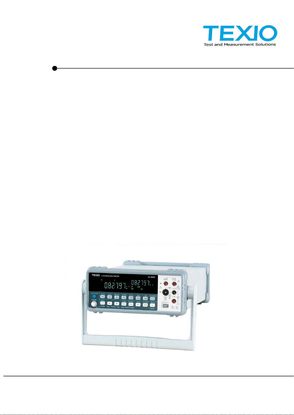
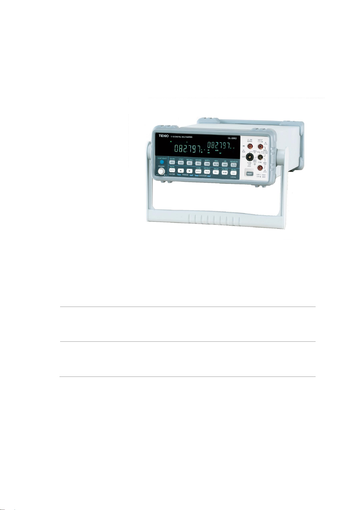
1-1. DL-2052 Characteristics
The DL-2052 is portable, dual-display digital multimeters suitable for wide range of applications, such as
production testing, research, and field verification.
1
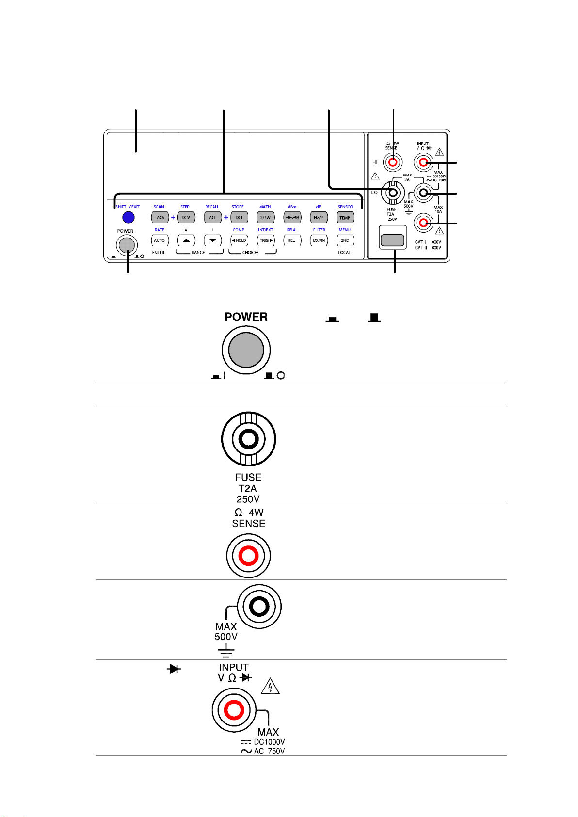
Display Key
Measurement
Keys
Main
Terminal
4W-R High
Fuse/
4W-R Lo
Power
Switch
Main
Display
DCI/ACI
Terminal
COM
Terminal
DISPLAY
Power Switch
Turns On or Off the main power. For power up
sequence, see page7.
Main Display
Shows measurement results and parameters.
For display configuration details, see page31 (light setting).
Input fuse / 4W Ω sense
LO terminal
As a fuse, protects the instrument from over-current.
Rating: T2A, 250V.
For fuse replacement procedure, see page47.
As a sense terminal, accepts 4W Ω measurement LO
connection. Also accepts current input less than 2A. For
details, see page12.
4W Ω Sense HI Terminal
Accepts HI sense line in 4W resistance measurement.
For details, see page12.
COM Terminal
Accepts ground (COM) line in all measurements except
the sense line in 4W Resistance (page12).
Voltage/ 2W Ω /
(Diode) Terminal
Accepts input in all measurements except for DC/AC
Current and 4W Resistance sense line.
1-2. Front Panel Overview
2
Current Terminal
Accepts DC/AC Current input.
For DCI/ACI details, see page11.
Display key
Display
Turns the display on or off. When the display is turned
off, all panel keys except the Display key become
disabled. The Display key is On by default.
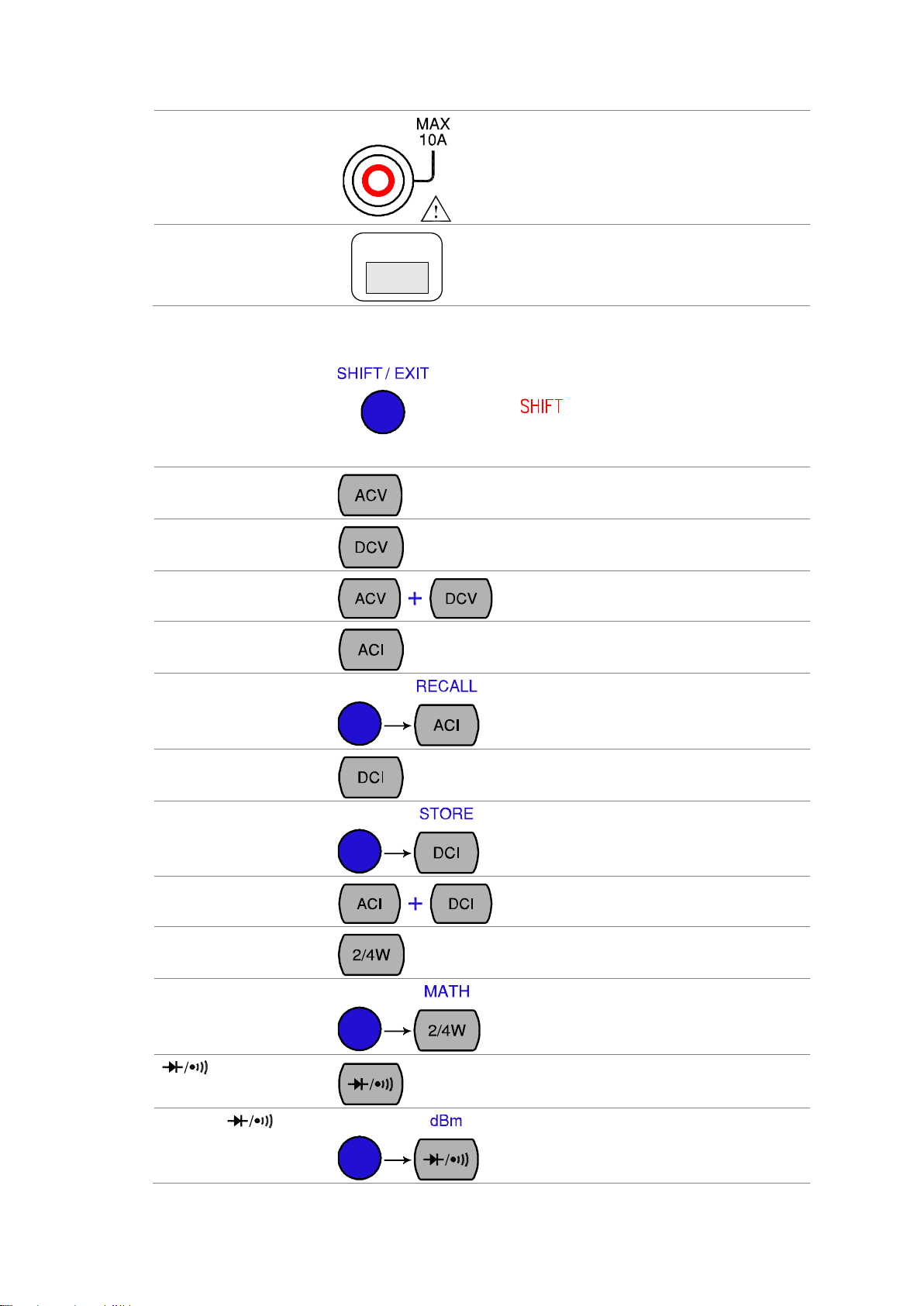
SHIFT/EXIT
As the Shift key, selects the second functionality
assigned to each front panel key. When pressed,
the indicator appears in the display.
As the Exit key, gets out of the parameter
configuration mode and goes back to the
measurement result display mode.
ACV
Measures AC Voltage (page9).
DCV
Measures DC Voltage (page9).
ACV + DCV
When the ACV key and the DCV key are pressed
together, they measure AC+DC Voltage (page9).
ACI
Measures AC Current (page11).
SHIFT → ACI (RECALL)
Recalls a normal measurement result (page32)
DCI
Measures DC Current (page11).
SHIFT → DCI (STORE)
Stores a measurement result (page32).
ACI + DCI
When the ACI key and the DCI key are pressed
together, they measure AC+DC Current (page11).
2/4W (Resistance)
Measures 2-wire or 4-wire Resistance (page12).
SHIFT → 2/4W (MATH)
Enters the Math measurement mode (page24).
(Diode/
Continuity)
Tests Diode (page13) or Continuity (page13).
SHIFT → (dBm)
Measures dBm (page20).
1-3. Measurement keys (Upper row)
3
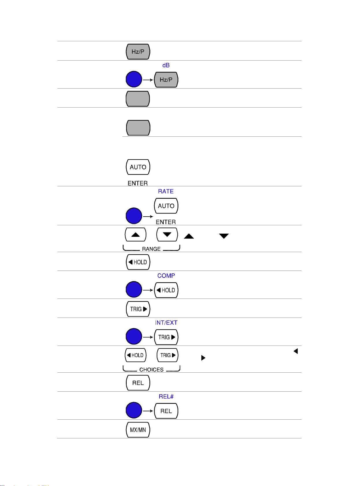
Hz/P (Frequency/ Period)
Measures Frequency or Period (page15).
SHIFT + Hz/P (dB)
Measures dB (page20).
(Temperature)
TEMP
Measures Temperature (page16).
SHIFT + TEMP
(SENSOR)
SENSOR
TEMP
Selects the type of thermocouple used in the
Temperature measurement (page17).
AUTO/ENTER
As the AUTO key, selects the measurement range
automatically.
As the ENTER key, confirms the entered value.
SHIFT → AUTO (RATE)
Selects the measurement update rate: Slow,
Medium, or Fast (page8).
Up/Down
Selects the parameter in various occasions: higher
( ) or lower ( ).
HOLD
Activates the Hold function (page22).
SHIFT → HOLD
(COMPare)
Activates the Compare measurement (page22).
TRIG (Trigger)
Triggers sample acquisition manually (page28).
SHIFT → TRIG (Int/Ext
Trigger)
Selects the Internal or the External trigger source
(page28).
Left/Right
Selects the parameter in various occasions: left ( )
or right ( ).
REL
Measures the Relative value (page21).
SHIFT → REL (RELative
base)
Manually sets the reference value for the Relative
value measurement (page21).
MX/MN
(MAX/ MIN)
Measures the Maximum or the Minimum value
(page21).
1-4. Measurement keys (Lower row)
4
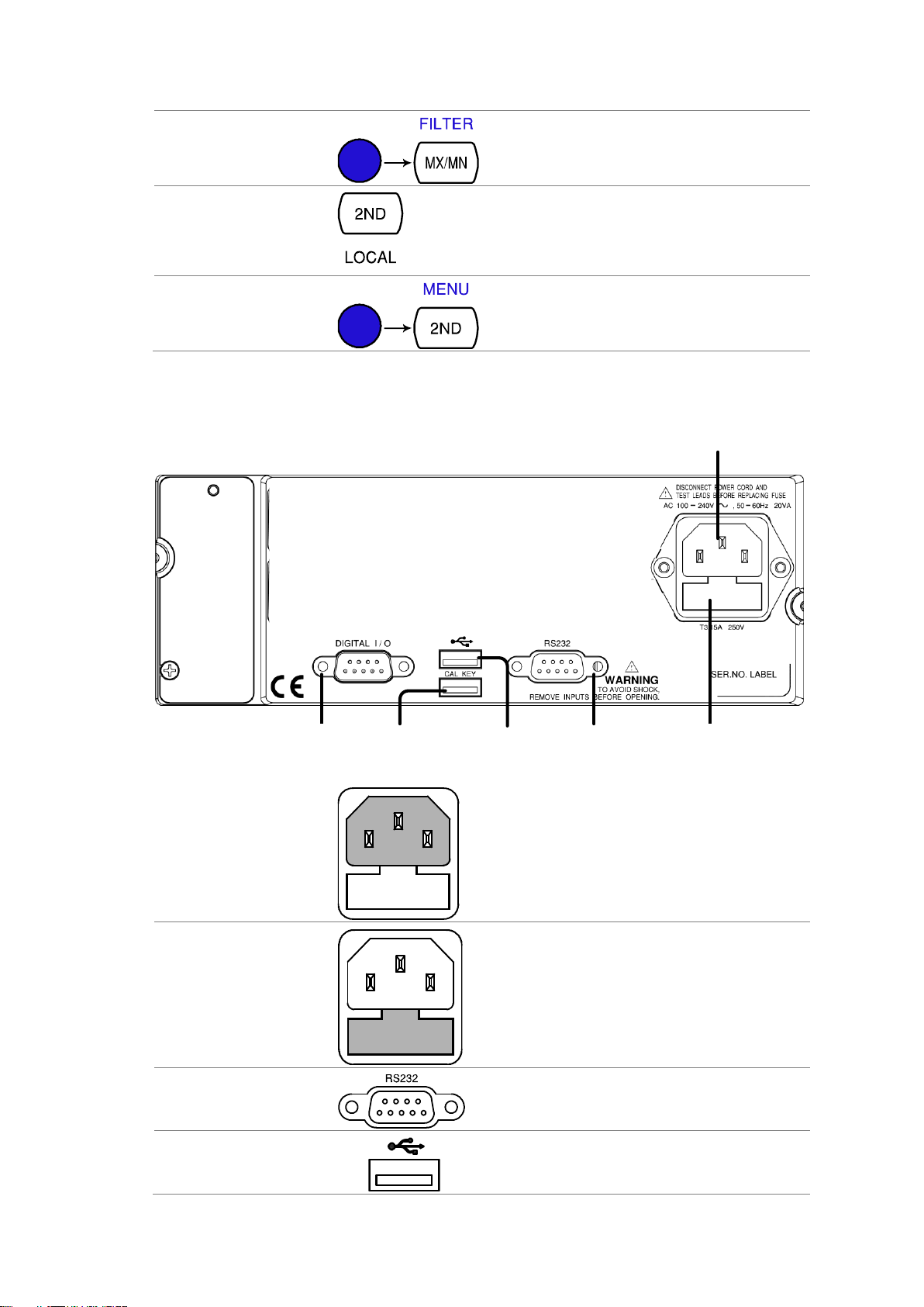
SHIFT → MX/MN
(FILTER)
Selects the digital filter type for the signal sampling
(page30).
2ND (Display) / LOCAL
As the 2nd key, selects the measurement item on
the 2nd display (page27). Pressing and holding for
more than 1 second turns off the 2nd display.
As the Local key, releases the remote control and
goes back to the local panel operation
SHIFT → 2ND (Menu)
Enters the configuration mode. Configures or
displays the following items: Display (page28),
Beep (page15), Continuity threshold (page14),
Digital I/O (page33), and System information
RS- 232 C
Port
Power Code
Socket
Fuse
T3.15A/ 250V
CAL Key
Port
Digital I/O
Port
USB Device
Port
Power Cord Socket
Accepts the power cord. AC 100–240V, 50–60Hz.
For power on sequence, see page7.
Fuse Socket
Holds the main fuse: T3.15A 250V, 20VA.
For fuse replacement details, see page46.
RS-232C port
Accepts an RS-232C cable for remote control; DB-9
male connector.
For remote control details, see page38.
USB device port
Accepts a USB device cable for remote control; Type
A, female connector.
For remote control details, see page37.
1-5. Rear Panel Overview
5
CAL key port
CAL KEY
Reserved for internal uses as in firmware update and
calibration.
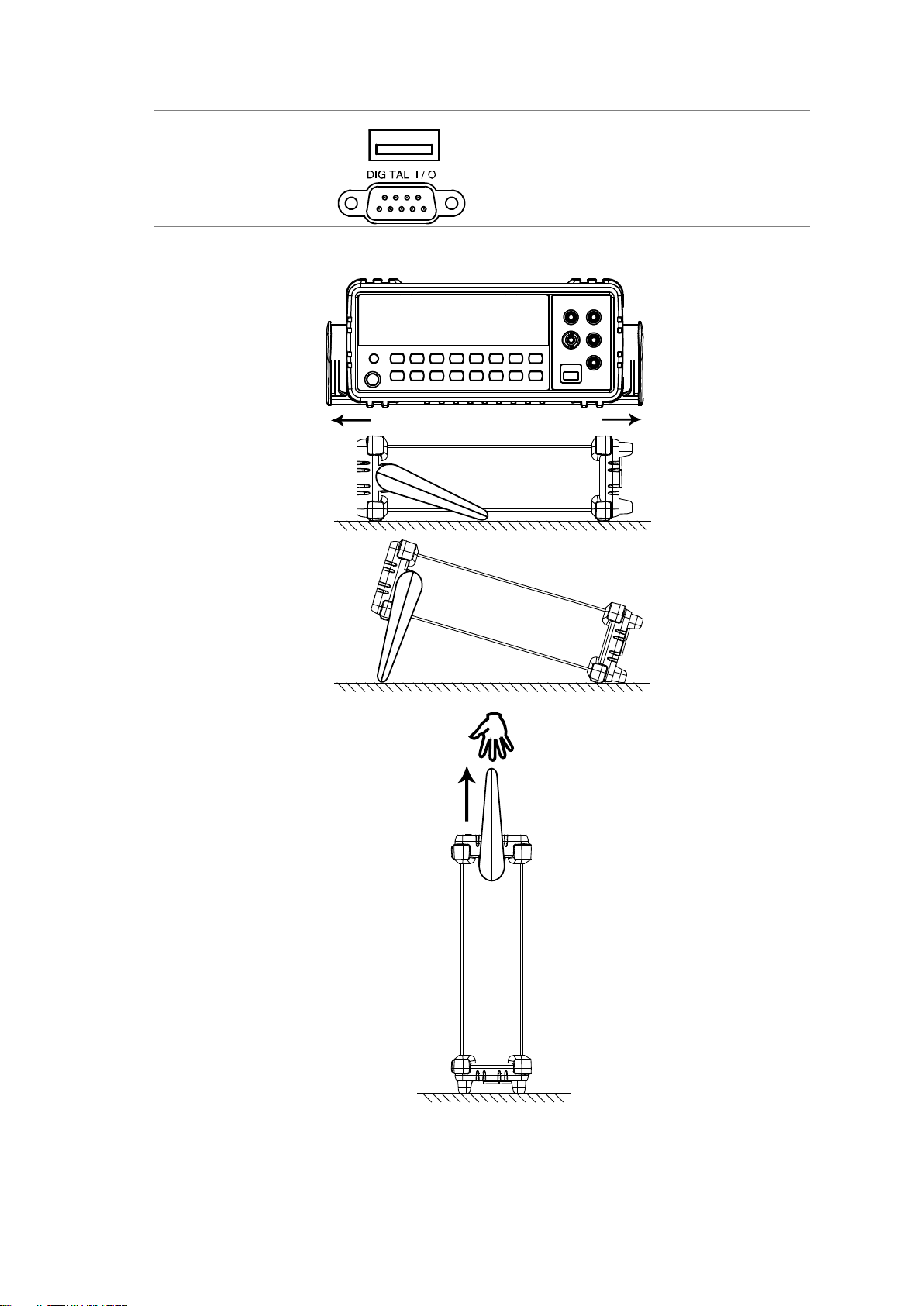
Digital I/O port
Accepts a digital I/O cable for the Hi/Lo limit test;
DB-9 pin, female connector.
For digital I/O details, see page34.
Tilt stand steps
Pull out the handle
sideways and rotate it.
Place the unit
horizontally,
Or in the tilt stand
position.
Place the handle
vertically for hand carry.
1-6. Set Up
6
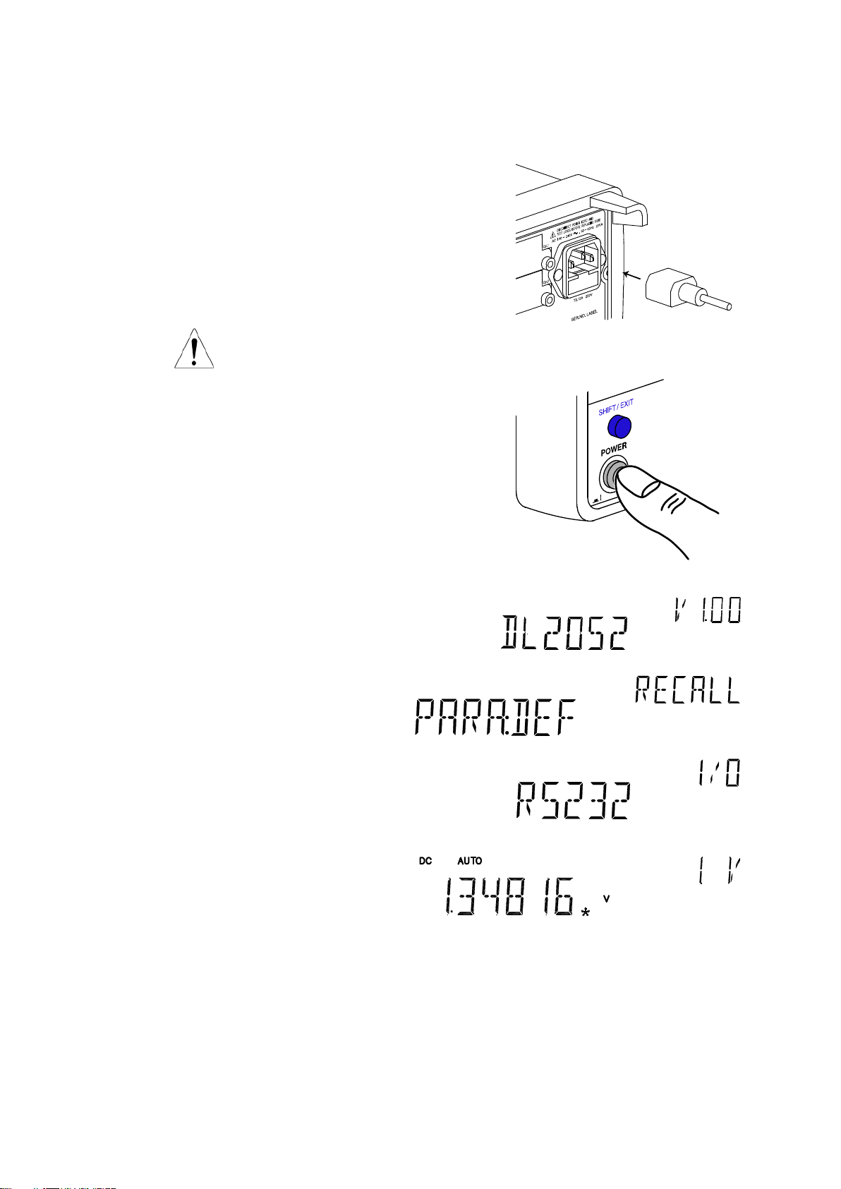
Power up steps
1. Connect the power cord to the
AC Voltage input.
Note
Make sure the ground connector of the power cord is connected to a
safety ground. This will affect the measurement accuracy.
2. Push to turn On the main
power switch on the front
panel.
3. The display shows the model name and the version for a few seconds.
Example: DL-2052, V1.00
4. Followed by the default measurement settings.
5. And the interface I/O settings.
6. Then the default setting appears.
Example: DCV, Auto, 1V range
1-7. Power Up
7
Background
Basic measurement refers to the eight types of measurements assigned to the
upper row keys on the front panel.
DCV ACI DCI
2/4W
/
ACV
Hz/P
TEMP
Measurement type
ACV
AC Voltage
DCV
DC Voltage
ACV+DCV
AC+DC Voltage
ACI
AC Current
DCI
DC Current
ACI+DCI
AC+DC Current
2/4W
2-wire and 4-wire Resistance
Diode/Continuity
Hz/P
Frequency/Period
TEMP
Celsius/Fahrenheit Temperature
Advanced
measurement
Advanced measurement (page19) mainly refers to the operation using the result
obtained from one or more of the basic measurement.
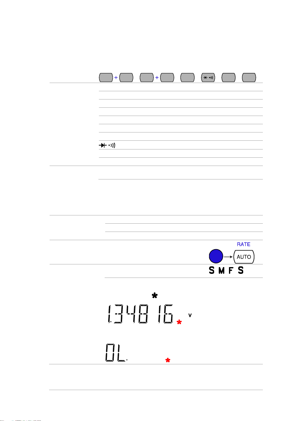
Background
Refresh rate defines how frequently the DL-2052 captures and updates the
measurement data. Faster refresh rate yields lower accuracy and resolution.
Slower refresh rate yields higher accuracy and resolution. Consider these
trade-offs when selecting the refresh rate.
Range
S
5 1/2 digits(119999 count)
M 4 1/2 digits
F 3 1/2 digits
Selection step
1. Press the Shift key followed by the AUTO
(RATE) key. The refresh rate switches to the
next.
2. The refresh rate indicator shows the current
status.
→ → →
Background
The reading indicator next to the 1st display flashes according to the
refresh rate setting.
When no data is captured
When there is no captured data, the reading indicator flashes once every two
seconds (slower than the normal refresh rate), indicating the DMM is in the
waiting mode.
Automatic triggering
(default)
The DL-2052 triggers according to the refresh rate. See the previous page for
refresh rate setting details.
2. BASIC MEASUREMENT
2-1. Basic Measurement Overview
2-2. Common attribute: refresh rate
2-3. Common attribute: reading indicator
2-4. Common attribute: manual/automatic triggering
8
Manual triggering
Press the TRIG key to trigger measurement
manually.
Voltage type
AC
0 ~ 750V
DC
0 ~ 1000V
AC+DC
0 ~ 1000V
AC2+DC
2
*AC+DC=
(AC = true RMS)
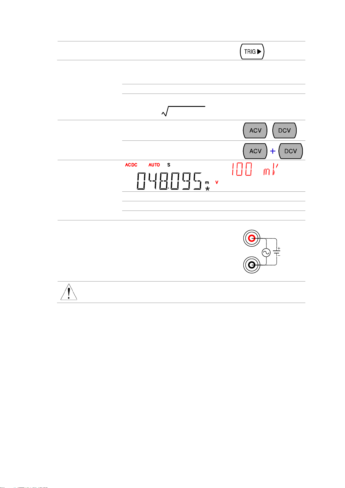
1. Activate ACV/ DCV
Press the ACV (AC Voltage) key or DCV (DC
Voltage) key.
or
For AC+DC Voltage, press the ACV key and the
DCV key together.
2. ACV/DCV mode
display appears
AC(DC) + V
Indicates AC, DC, AC+DC Voltage
AUTO
Indicates Automatic range selection
100mV
2nd display shows the Voltage range
3. Connect the test lead
and measure
Connect the test lead between the V and the COM
port. The display updates the reading.
V
COM
Note
When measuring in1000V (maximum) range immediately followed by 100mV
(minimum) range, an error might occur due to extreme range switching. In such
case, take at least one minute in between as an interval.
2-5. AC/DC/AC+DC Voltage Measurement
9

Auto range
To turn the automatic range selection On/Off, press
the AUTO key.
Manual range
Press the Up or the Down key to select the range.
AUTO indicator turns Off automatically. If the
appropriate range is unknown, select the highest
range.
Selection list
Range
Resolution / Full scale @ slow rate
Resolution
Full scale
100mV
1µV
120.000mV
1V
10µV
1.20000V
10V
100µV
12.0000V
100V
1mV
120.000V
750V (AC)
10mV
750.00V
1000V(DC, AC+DC)
10mV
1000.0V
Note
For more detailed parameters, see the specifications at page49.
Waveform
Peak to Peak
AC
(True RMS)
DC
AC + DC
(True RMS)
Sine
PK-PK
2.828
1.000
0.000
1.000
Rectified Sine (full
wave)
PK-PK
1.414
0.435
0.900
1.000
Rectified Sine (half
wave)
PK-PK
2.000
0.771
0.636
1.000
Square
PK-PK
2.000
1.000
0.000
1.000
Rectified Square
PK-PK
1.414
0.707
0.707
1.000
Rectangular Pulse
PK-PK
X
Y
2.000
2K
K=
)2
( DD
D=X/Y
2D
D=X/Y
2
D
D=X/Y
Triangle Sawtooth
PK-PK
3.464
1.000
0.000
1.000
2-6. Select Voltage range
2-7. Voltage conversion table
This table shows the relationship between AC, DC, and AC+DC reading in various waveforms.
10
Background
Crest factor is the ratio of the peak signal amplitude to the RMS value of the
signal. It determines the accuracy of AC measurement.
If the crest factor is less than 3.0, voltage measurement will not result in error due
to dynamic range limitations at full scale.
If the crest factor is more than 3.0, it usually indicates abnormal waveform as
seen from the below table.
Waveform
Shape
Crest factor
Square wave 1.0
Sine wave
1.414
Triangle sawtooth 1.732
Mixed frequencies
1.414 ~ 2.0
SCR output 100% ~
10%
1.414 ~ 3.0
White noise 3.0 ~ 4.0
AC Coupled pulse
train
3.0
Spike
>9.0
Current type
AC
0 ~ 10A
DC
0 ~ 10A
AC+DC
0 ~ 10A
AC2+DC
2
*AC+DC=
(AC = true RMS)
1. Activate ACI/ DCI
Press the ACI (AC Current) key or the DCI (DC
Current) key.
or
For AC+DC Current, press the ACI key and the
DCI key together.
2. ACI/DCI mode display
appears
AC(DC) + A
Indicates AC, DC, AC+DC Current
(Note: AC = true RMS)
2-8. Crest factor table
2-9. AC/DC/AC+DC Current Measurement
11
AUTO
Indicates Automatic range selection
10A
2nd display shows the Current range
3. Connect the test lead
and measure
Connect the test lead between the A
and COM port or LO to COM port,
depending on the current. For current ≤
2A use the LO port; For current up to
10A use the A port. The display
updates the reading.
A
COM
LO
MAX
2A
Auto range
To turn the automatic range selection On/Off, press
the AUTO key.
Manual range
Press the Up or the Down key to select the range.
AUTO indicator turns Off automatically. If the
appropriate range is unknown, select the highest
range.
Selection list
Range
Resolution / Full scale @ slow rate
Resolution
Full scale
10mA
0.1µA
12.0000mA
100mA
1µA
120.000mA
1A
100µA
1.2000A
10A
100µA
10.0000A
Note
*10A range is not available for AC+DC Current.
For more detailed range, see the specifications at page50.
Measurement type
2-wire
Uses the standard V-COM ports.
Recommended for measuring resistances larger than 1kΩ.
4-wire
Compensates the test lead effect using the 4W compensation
ports, in addition to the standard V-COM ports.
Recommended for measuring sensitive resistances smaller
than 1kΩ.
1. Activate resistance
measurement
For 2-wire resistance measurement, press the
2W/4W key once.
For 4-wire resistance measurement, press the
2W/4W key twice.
2. 2W resistance mode
display appears
2W(4W) + Ω
Indicates 2W(4W) Resistance mode
AUTO
Indicates Automatic range selection
10M
2nd display shows the Resistance range
3. Connect the test lead
and measure
Connect the test lead. For 2-wire resistance, use the Ω (V) and the COM port.
For 4-wire resistance, use the Ω (V) and the COM port, plus the 4W sense, and
LO port for sensing. The display updates the reading.
2-10. Select Current range
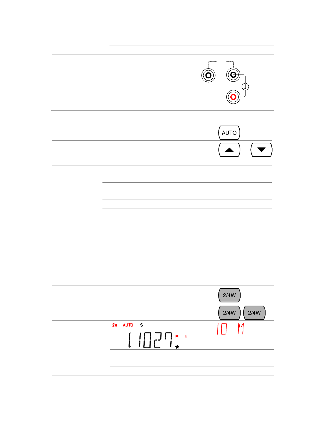
2-11. 2W/4W Resistance Measurement
12
 Loading...