

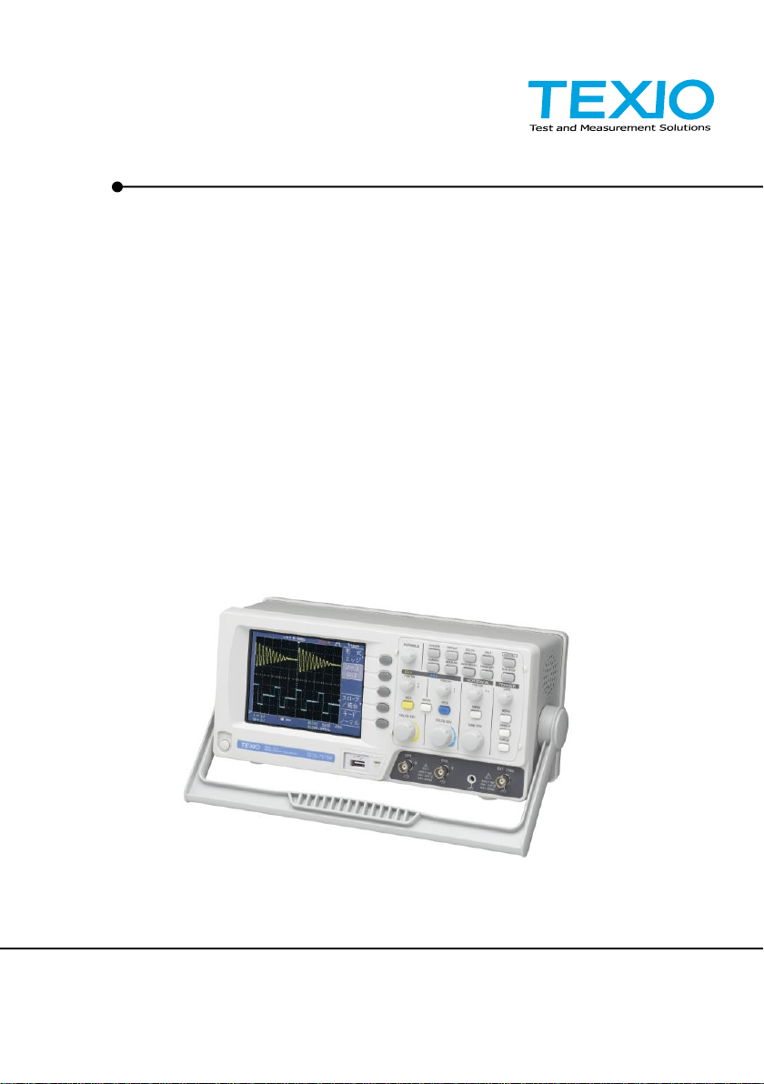
PROGRAMMING MANUAL
DIGITAL STORAGE OSCILLOSCOPE
DCS-7500A SERIES
DCS-7507A DCS-7510A DCS-7515A
B71-0048-01

■ About a trademark, a registered trademark
A company name and the brand name mentioned in this instruction
manual are the trademark or the registered trademark of each
company or group in each country and region.
■ About this instruction manual
When copying the part or all of contents of this instruction manual, seek
the copyright holder.
In addition, the specifications of the product and the contents of this
instruction manual are subject to change without notice for
improvement. Please check to our website for the latest version.

CONTENTS
1. INTERFACE OVERVIEW ........................ 1
1-1. Rear Panel Overview ........................................ 1
1-2. Configuring the USB Interface ........................... 1
2. COMMAND OVERVIEW ......................... 3
2-1. Command Syntax ............................................. 3
3. COMMAND DETAILS ............................. 4
3-1. System Command ............................................ 5
3-1-1. *IDN .......................................................................................... 5
3-1-2. *LRN ......................................................................................... 6
3-1-3. *RST ......................................................................................... 6
3-1-4. :SYSTem:ERRor ....................................................................... 7
3-1-5. SYSTem:VERSion .................................................................... 7
3-2. Acquisition Command ....................................... 8
3-2-1. :ACQuire:AVERage .................................................................. 8
3-2-2. :ACQuire:HDELay ..................................................................... 9
3-2-3. :ACQuire:MODe ........................................................................ 9
3-2-4. :ACQuire<X>:LMEMory .......................................................... 10
3-2-5. :ACQuire<X>:MEMory ............................................................ 12
3-3. Autoset Command .......................................... 13
3-3-1. :AUToset ................................................................................. 13
3-4. Channel / Math Command .............................. 14
3-4-1. :CHANnel<X>:BWLimit ........................................................... 14
3-4-2. :CHANnel<X>:COUPling ........................................................ 15
3-4-3. :CHANnel<X>:DISPlay ........................................................... 15
3-4-4. :CHANnel<X>:EXPand ........................................................... 16
3-4-5. :CHANnel<X>:INVert .............................................................. 16
3-4-6. :CHANnel<X>:MATH .............................................................. 17
3-4-7. :CHANnel<X>:OFFSet ............................................................ 18
3-4-8. :CHANnel<X>:PROBe:RATio ................................................. 19
3-4-9. :CHANnel<X>:PROBe:TYPE .................................................. 19
3-4-10. :CHANnel<X>:SCALe ........................................................... 20
3-5. Math Command .............................................. 21
3-5-1. :MATH:OPERator ................................................................... 21
3-5-2. :MATH:POSition ...................................................................... 22
3-5-3. :MATH:FFT:SOURce ................................ .............................. 22
3-5-4. :MATH:FFT:WINDow ................................ .............................. 23
3-5-5. :MATH:FFT:SCALe ................................................................. 23
3-5-6. :MATH:FFT:HORizontal:SCALe .............................................. 24
3-5-7. :MATH:FFT:HORizontal:POSition ........................................... 24

3-6. Cursor Command ........................................... 25
3-6-1. :CURSor:X<X>Position ........................................................... 25
3-6-2. :CURSor:Y<X>Position ........................................................... 26
3-6-3. :CURSor:<X>DELta ................................................................ 27
3-6-4. :CURSor:<X>DISplay ............................................................. 28
3-6-5. :CURSor:SOURce .................................................................. 28
3-7. Display Command .......................................... 29
3-7-1. :DISPlay:ACCumulate ............................................................. 29
3-7-2. :DISPlay:CONTrast ................................................................. 30
3-7-3. :DISPlay:GRATicule ................................................................ 30
3-7-4. :DISPlay:WAVeform ................................................................ 31
3-7-5. :REFResh ............................................................................... 31
3-8. Measure Command ........................................ 32
3-8-1. :MEASure:DELAY1 ................................................................. 33
3-8-2. :MEASure:DELAY2 ................................................................. 33
3-8-3. :MEASure:FALL ...................................................................... 34
3-8-4. :MEASure:FFFDelay ............................................................... 34
3-8-5. :MEASure:FFRDelay .............................................................. 35
3-8-6. :MEASure:FOVShoot .............................................................. 35
3-8-7. :MEASure:FPReshoot ............................................................. 36
3-8-8. :MEASure:FREQuency ........................................................... 36
3-8-9. :MEASure:FRFDelay .............................................................. 37
3-8-10. :MEASure:FRRDelay ............................................................ 37
3-8-11. :MEASure:LFFDelay ................................ ............................. 38
3-8-12. :MEASure:LFRDelay ............................................................. 38
3-8-13. :MEASure:LRFDelay ............................................................. 39
3-8-14. :MEASure:LRRDelay ............................................................ 39
3-8-15. :MEASure:NWIDth ................................................................ 40
3-8-16. :MEASure:PDUTy ................................................................. 40
3-8-17. :MEASure:PERiod ................................................................ 41
3-8-18. :MEASure:PWIDth ................................................................ 41
3-8-19. :MEASure:RISe ..................................................................... 42
3-8-20. :MEASure:ROVShoot ........................................................... 42
3-8-21. :MEASure:RPReshoot .......................................................... 43
3-8-22. :MEASure:SOURce .............................................................. 43
3-8-23. :MEASure:VAMPlitude .......................................................... 44
3-8-24. :MEASure:VAVerage ............................................................ 44
3-8-25. :MEASure:VHI ....................................................................... 45
3-8-26. :MEASure:VLO ..................................................................... 45
3-8-27. :MEASure:VMAX .................................................................. 46
3-8-28. :MEASure:VMIN .................................................................... 46
3-8-29. :MEASure:VPP ..................................................................... 47
3-8-30. :MEASure:VRMS .................................................................. 47
3-9. Go No-Go Command ...................................... 48
3-9-1. :GONogo:CLEar ...................................................................... 48
3-9-2. :GONogo:EXECute ................................................................. 49
3-9-3. :GONogo:FUNCtion ................................................................ 49

3-9-4. :GONogo:NGCount? ............................................................... 50
3-9-5. :GONogo:NGDefine ................................................................ 50
3-9-6. :GONogo:SOURce .................................................................. 51
3-9-7. :GONogo:VIOLation ................................................................ 51
3-9-8. :TEMPlate:MODe .................................................................... 52
3-9-9. :TEMPlate:MAX ...................................................................... 53
3-9-10. :TEMPlate:MIN ...................................................................... 54
3-9-11. :TEMPlate:POSition:MAX ..................................................... 55
3-9-12. :TEMPlate:POSition:MIN ...................................................... 56
3-9-13. :TEMPlate:SAVe:MAXimum.................................................. 57
3-9-14. :TEMPlate:SAVe:MINimum ................................................... 57
3-9-15. :TEMPlate:TOLerance .......................................................... 58
3-9-16. :TEMPlate:SAVe:AUTo ......................................................... 59
3-10. Data Logging Command ............................... 60
3-10-1. :DATALOG:STATE ............................................................... 60
3-10-2. :DATALOG:SOURce ............................................................. 60
3-10-3. :DATALOG:SAVe .................................................................. 61
3-10-4. :DATALOG:INTerval ............................................................. 61
3-10-5. :DATALOG:DURation ........................................................... 62
3-11. Save/Recall Command .................................. 63
3-11-1. :MEMory<X>:RECall:SETup ................................................. 63
3-11-2. :MEMory<X>:RECall:WAVeform ........................................... 64
3-11-3. :MEMory<X>:SAVe:SETup ................................................... 64
3-11-4. :MEMory<X>:SAVe:WAVeform ............................................. 65
3-11-5. *RCL ..................................................................................... 65
3-11-6. :REF<X>:DISPlay ................................................................. 66
3-11-7. :REF<X>:LOCate .................................................................. 66
3-11-8. :REF<X>:SAVe ..................................................................... 67
3-11-9. *SAV ..................................................................................... 67
3-12. Time (Horizontal) Command .......................... 68
3-12-1. :TIMebase:DELay ................................................................. 68
3-12-2. :TIMebase:SCALe ................................................................. 69
3-12-3. :TIMebase:SWEep ................................................................ 70
3-12-4. :TIMebase:WINDow:DELay .................................................. 70
3-12-5. :TIMebase:WINDow:SCALe.................................................. 71
3-13. Trigger Command ......................................... 72
3-13-1. :FORCe ................................................................................. 72
3-13-2. :RUN ..................................................................................... 72
3-13-3. :SINGle ................................................................................. 73
3-13-4. :STOP ................................................................ ................... 73
3-13-5. *TRG ..................................................................................... 73
3-13-6. :TRIGger:COUPle ................................................................. 74
3-13-7. :TRIGger:FREQuency ........................................................... 74
3-13-8. :TRIGger:HOLDoff ................................................................ 75
3-13-9. :TRIGger:LEVel ..................................................................... 75
3-13-10. :TRIGger:MODe .................................................................. 76
3-13-11. :TRIGger:NREJ ................................................................... 76

3-13-12. :TRIGger:PULSe:MODe ..................................................... 77
3-13-13. :TRIGger:PULSe:TIMe ........................................................ 78
3-13-14. :TRIGger:REJect ................................................................. 78
3-13-15. :TRIGger:SLOPe ................................................................. 79
3-13-16. :TRIGger:STATe ................................................................. 80
3-13-17. :TRIGger:SOURce .............................................................. 81
3-13-18. :TRIGger:TYPe ................................................................... 81
3-13-19. :TRIGger:VIDeo:FIELd ........................................................ 82
3-13-20. :TRIGger:VIDeo:LINe .......................................................... 83
3-13-21. :TRIGger:VIDeo:POLarity ................................................... 84
3-13-22. :TRIGger:VIDeo:TYPe ........................................................ 84
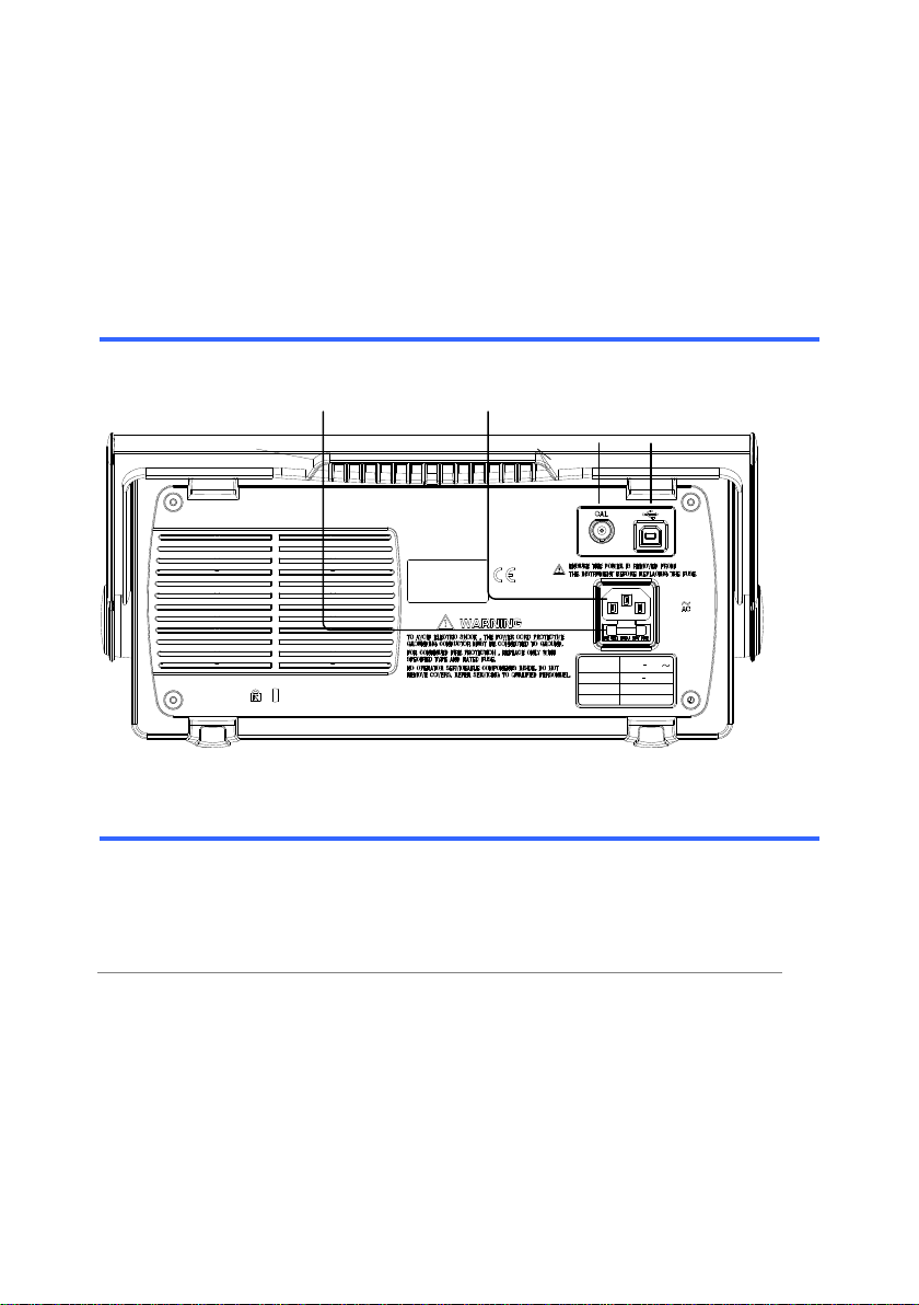
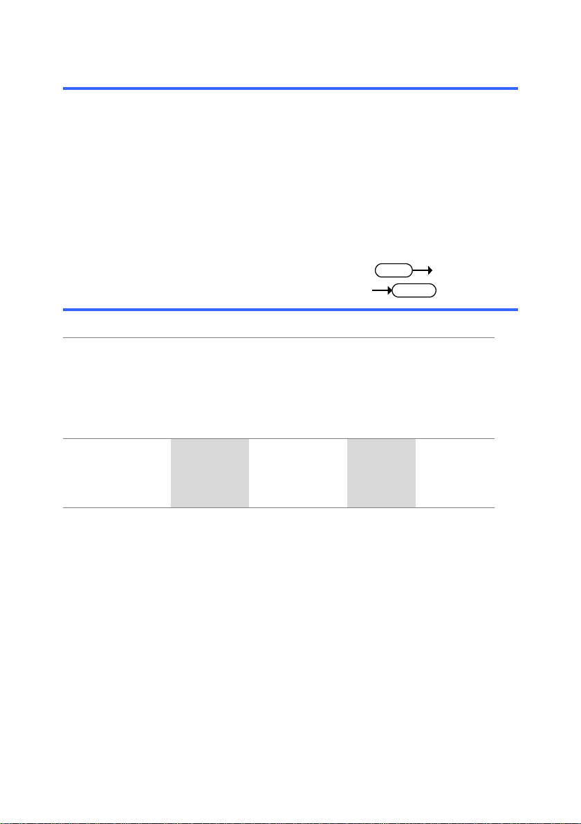
1
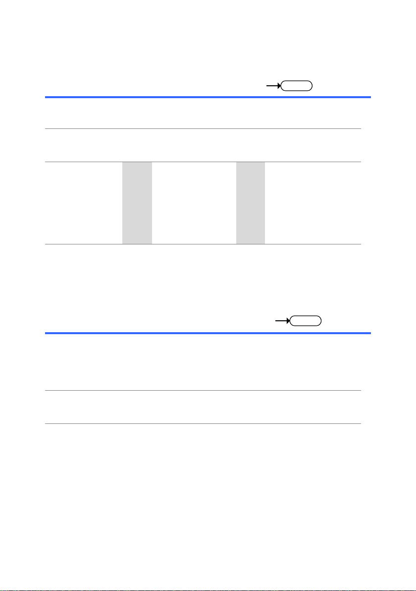
LINE VOLTAGE
AC 100 240V
FUSE RATING
RANGE
T1A 250V
FREQUENCY 50 60Hz
POWER MAX. 18W 40VA
USB portCAL outputPower cord socketFuse socket
USB connection
PC side
connector
Type A, host
DCS-7500A
side connector
Type B, device
Speed
1.1/2.0 (full speed)
1.INTERFACE OVERVIEW
This manual describes how to use the DCS-7500A series’ remote
command functionality and lists the command details. The Overview
chapter describes how to configure the DCS-7500A series USB remote
control interface.
1-1.Rear Panel Overview
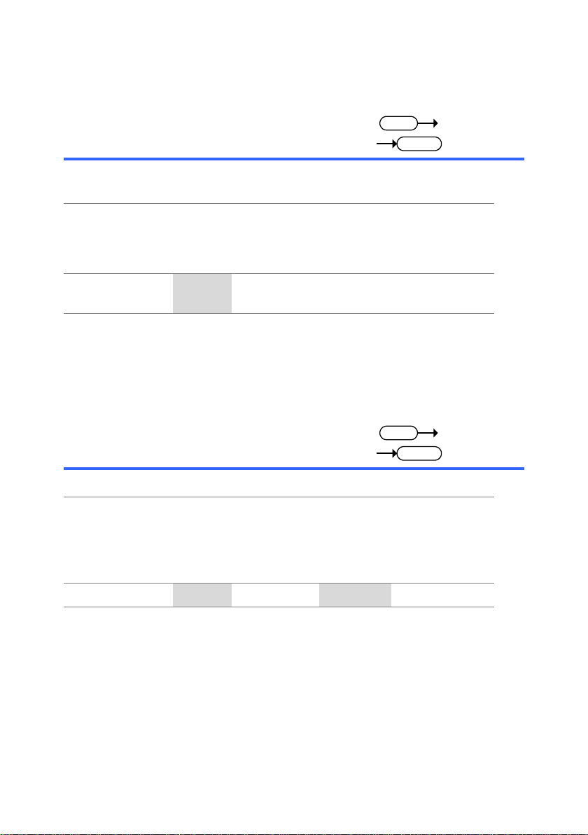
1-2.Configuring the USB Interface
2
USB driver
software
OS
Microsoft Windows 7 or higher
File name
TEXIO_CDC.inf (Attached CD)
DCS-7500A is allocated to the COM port when
installing it. The set is recognized as a serial
communications equipment on PC. You must have
administrator account to install.
Serial port setting:
Speed 12Mbps or less
Data-bits
: 8 bit
Parity
: none
Stop-bit
: 1 bit
Flow-control
: none
Panel operation
1. Connect the USB cable to the
USB device port on the rear.
2. When the PC asks for the USB driver or
‘Unknown device’ listed in Device Manager,
install TEXIO_CDC.inf attached CD.
3. On the PC, activate a terminal application such
as PuTTY. To check the COM port No., see the
Device Manager in the PC.
4. Run this query command via the terminal
application.
*idn?
This command should return the manufacturer,
model number, serial number, and firmware
version in the following format.
TEXIO, DCS-75XXA, XXXXXXX, V1.00
5. Configuring the command interface is completed.
Refer to the other chapters for more details.
CAUTION:
If there is no response, please confirm a device
driver, COM port number or the connection of the
cable and so on.
CAUTION:
If you change the setting of the USB port in the
connection with the PC, May not be able to
communicate. Please restart your PC in this case.
3
Compatible
standard
USB CDC_ACM compatible
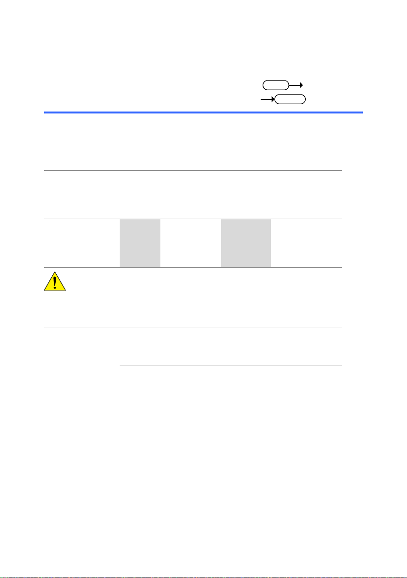
SCPI, 1994 (partially compatible)
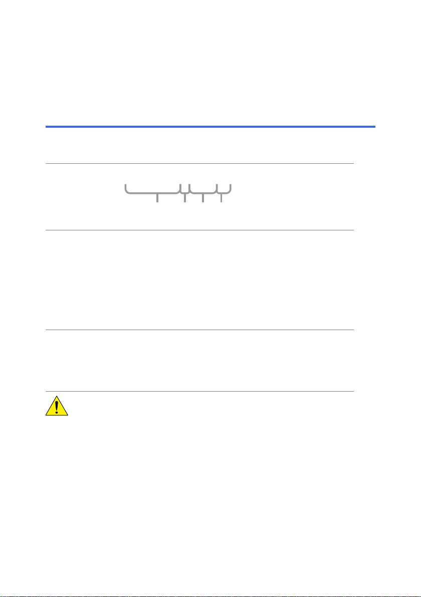
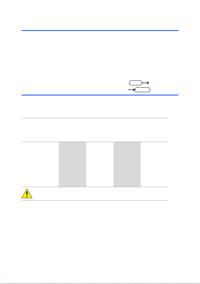
Command
format
trig:del:mod <NR1>LF
1 2 3 4
1: command header
2: single space
3: parameter
4: message terminator
Parameter
Type
Description
Example
<Boolean>
boolean logic
0, 1 <NR1>
Integers
0, 1, 2, 3
<NR2>
decimal numbers
0.1, 3.14, 8.5
<NR3>
floating point
4.5e-1, 8.25e+1
<NRf>
any of NR1, 2, 3
1, 1.5, 4.5e-1
Message
terminator
LF^END
line feed code (hexadecimal 0A)
with END message
LF
line feed code
<dab>^END
last data byte with END message
CAUTION:
Commands are non-case sensitive.
On the real input of the value to the parameter,
please do not use the symbol as “<”, “>”, “|”.
The above symbols are used to facilitate
distinction with this manual.
2.COMMAND OVERVIEW
The command syntax section shows you the basic syntax rules you have
to apply when using commands.
2-1.Command Syntax

4
3-1. System Command ............................................ 5
3-2. Acquisition Command ....................................... 8
3-3. Autoset Command .......................................... 13
3-4. Channel / Math Command .............................. 14
3-5. Math Command .............................................. 21
3-6. Cursor Command ........................................... 25
3-7. Display Command .......................................... 29
3-8. Measure Command ........................................ 32
3-9. Go No-Go Command ...................................... 48
3-10. Data Logging Command ............................... 60
3-11. Save/Recall Command .................................. 63
3-12. Time (Horizontal) Command .......................... 68
3-13. Trigger Command ......................................... 72
3.COMMAND DETAILS

5
3-1-1. *IDN .......................................................................................... 5
3-1-2. *LRN ......................................................................................... 6
3-1-3. *RST ......................................................................................... 6
3-1-4. :SYSTem:ERRor ....................................................................... 7
3-1-5. :SYSTem:VERSion ................................................................... 7
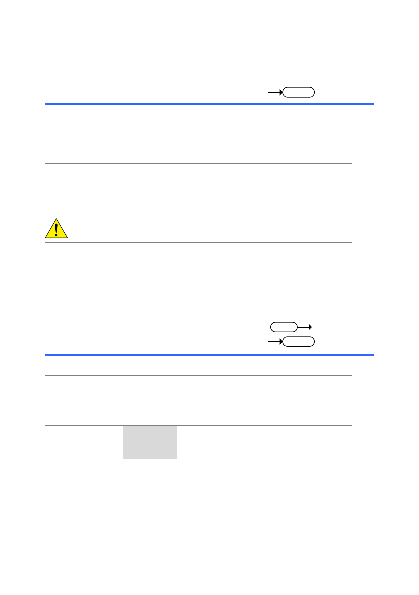
Query
Description
Returns the oscilloscope ID: manufacturer, model
name, serial number, and firmware version.
Same as: Utility key → F4
Syntax
*idn?
Example
*idn?
TEXIO, DCS-7515A, XXXXXXX, V1.00
Returns
the ID
A kind of Query or Set is
shown.
Query
: Query
Set
: Set
3-1.System Command
3-1-1.*IDN

6
Query
Description
Returns the oscilloscope settings as a data string.
Syntax
*lrn?
Example
*lrn?
:DISPlay:WAVeform 0;ACCumulate 0;CONTrast 0;GRATicule
0;:CHANnel1:DISPlay 1;BWLimit 0;COUPling 0;INVert
0;OFFSet 2.000e+00;PROBe 3;SCALe
2.000e+00;:CHANnel2:DISPlay 1;BWLimit 0;COUPling 0;INVert
0;OFFSet 2.000e+00;PROBe 3;SCALe
2.000e+00;:CHANnel1:MATH 0;:TIMebase:SWEep 0;SCALe
2.500e-06;DELay 0.000e+00;WINDow:SCALe
2.50000e-07;DELay 0.00000e+00;:ACQuire:MODe 0;AVERage
0;:TRIGger:TYPe 0;SOURce 0;MODe 1;SLOP 0;COUPle
1;REJect 0;NREJ 0;LEVel 0.00000e+00;PULSe:MODe: 0;TIMe
0.00000e+00;:VIDeo:TYPe 1;POLarity 0;FIELd 0;LINe
0;:CURSor:SOURce 1;XDISPlay 0;X1Position 75;X2Position
175;YDISPlay 0;Y1Position 54;Y2Position 154;:REF1:DISPlay
0;LOCate 50;:REF2:DISPlay 0;LOCate -50;:RUN
Set
Description
Resets the DCS-7500A (recalls the default panel
settings).
Same as: Save/Recall key → F1
Syntax
*rst
CAUTION:
In the help mode (the screen display of the function
explanation), the command is invalid.
CAUTION:
The saved content in the internal memory is not
initialized by the recall function of “Default Setup”.
3-1-2.*LRN
3-1-3.*RST
7
Query
Description
Returns the oscilloscope system error message, if
there is any.
Syntax
< Long >
< Short >
:system:error?
:syst:err?
Parameter
ID
Contents
ID
Contents
-100
command error
-102
syntax error
-220
parameter error
-221
settings conflict
-222
data out of range
-223
too much data
-224
illegal parameter
-232
invalid format
Example
:system:error?
-102
Indicates that the command
syntax is wrong.
Query
Description
Returns the SCPI version to which the oscilloscope
complies to. This is returned as the SCPI version
year and revision number (YYYY.V).
Syntax
< Long >
< Short >
:system:version?
:syst:vers?
Example
:syst:vers?
1992.0
Returns the SCPI version
as 1992.0
3-1-4.:SYSTem:ERRor
:
3-1-5.SYSTem:VERSion
8
3-2-1. :ACQuire:AVERage .................................................................. 8
3-2-2. :ACQuire:HDELay ..................................................................... 9
3-2-3. :ACQuire:MODe ........................................................................ 9
3-2-4. :ACQuire<X>:LMEMory .......................................................... 10
3-2-5. :ACQuire<X>:MEMory ............................................................ 12
Set
Query
Description
Selects or returns the average number of waveform
acquisition in the average acquisition mode.
Same as: Acquire key → F2
Syntax
< Long >
< Short >
:acquire:average <NR1>
:acquire:average?
:acq:aver <NR1>
:acq:aver?
Parameter
<NR1>
Average
No.
<NR1>
Average
No. 1 2 5
32
2 4 6
64
3 8 7
128
4 16 8 256
CAUTION:
Before using this command, select the average
acquisition mode. See the example below.
Example
:acquire:mode 2
:acquire:average 2
Selects the average
acquisition mode,
and select the average
number 4.
3-2.Acquisition Command
3-2-1.:ACQuire:AVERage
9
Set
Query
Description
Set or query Delay On or Delay Off.
Same as: Acquire key → F4
Syntax
< Long >
< Short >
:acquire:hdelay <Boolean>
:acquire:hdelay?
:acq:hdel <Boolean>
:acq:hdel?
Parameter
<NR1>
Delay
0 Off
1 On
Example
:acquire:hdelay 1
:acquire:hdelay?
1
Turns Delay On.
Returns the Delay as On.
Set
Query
Description
Selects or returns the acquisition mode.
Same as: Acquire key → F1 ~ F3
Syntax
< Long >
< Short >
:acquire:mode <NR1>
:acquire:mode?
:acq:mod <NR1>
:acq:mod?
Parameter
<NR1>
Mode
<NR1>
Mode
0 Normal
2
Average
1 Peak detect
Example
:acquire:mode 2
:acquire:average 2
Selects the average
acquisition mode,
and select the average
number 4.
3-2-2.:ACQuire:HDELay
3-2-3.:ACQuire:MODe
10
Query
Description
Returns the total waveform data in the acquisition
memory for long memory.
Syntax
< Long >
< Short >
:acquire<X>:lmemory?
:acq<X>:lmem?
Parameter
<X>
Channel
1/2
Channel1/2
CAUTION:
Please note that the number of points is limited to
4000 when the scope is running.
You can get the full memory depth when the
“Single” key is pressed with a triggered signal.
You can also get the full memory depth when the
“STOP” key is pressed,
However, the long memory may not fully fill up if a
slow time base is used with a fast sample rate
Also note that there are several time base settings
that don’t result in 100% of available memory, due
to a limited number of available sample rates.
Example
:acquire1:lmemory?
Returns the channel 1
long memory waveform
data
If both channels are
active up to 1M points
are returned. If only CH1
is active then up to 2M
points are returned.
Data format
Six data elements are concatenated to form one
data string.
# A B C D E F
A: Data size digit
B: Data size
C: Time interval
D: Channel indicator
E: Reserved data
F: Waveform data
3-2-4.:ACQuire<X>:LMEMory

11
# (1 byte)
The start of data transfer. The value is 0X23
(“#” in ASCII code).
Data size digit (1 byte)
Indicates the number of digits used for the data
string that follows. The data size digit is 4 for 4000
points, 7 for 1M or 2M points.
Data size (4 or 7 bytes)
Indicates the data size. The data size varies from
8008 (4000 points), 2000008 (1M points) or
4000008 (2M points).
8 bytes are total of Time interval, Channel indicator,
and Reserved data.
Time interval (4 bytes)
Indicates the time interval between two adjacent
sampling points in the floating point format,
compatible with IEEE 754 standards.
Note: The data is sorted in the little-endian format.
Channel indicator (1 byte)
Indicates the channel, 1 (0X01) or 2 (0X02).
Reserved data (3 bytes)
An unused data block, 3 bytes.
Waveform data
(8000, 2000000 or 4000000 bytes)
The waveform data comprised of 2M data points.
Each point is made up of 2 bytes (16 bits), two's
complement, high byte (MSB) first.
Example 1M points data
Data size digit(7) Time interval(0X31 09 70 5F)
# Data size(2000008) Channel indicator(0X01)
Reserved data
Waveform data after this(FF)
Reserved data

12
Query
Description
Returns the total waveform data in the acquisition
memory.
Syntax
< Long >
< Short >
:acquire<X>:memory?
:acq<X>:mem?
Parameter
<X>
Channel
1/2
Channel1/2
Example
:acquire1:memory?
Returns the channel 1
waveform data.
Data format
Six data elements are concatenated to form one
data string.
# A B C D E F
A: Data size digit
B: Data size
C: Time interval
D: Channel indicator
E: Reserved data
F: Waveform data
# (1 byte)
The start of data transfer. The value is 0X23
(“#” in ASCII code).
Data size digit (1 bytes)
Indicates the number of digits used for the data
string that follows. The data size digit is always 4.
Data size (4 bytes)
Indicates the data size. The data size is always
8008 (4000 points per channel).
8 bytes are total of Time interval, Channel indicator,
and Reserved data.
Time interval (4 bytes)
Indicates the time interval between two adjacent
sampling points in the floating point format,
compatible with IEEE 754 standards.
Note: The data is sorted in the little-endian format.
Channel indicator (1 byte)
Indicates the channel, 1 (0X01) or 2 (0X02).
Reserved data (3 bytes)
An unused data block, 3 bytes.
Waveform data (8000 bytes)
The waveform data comprised of 4000 data points.
Each point is made up of 2 bytes (16 bits), two's
complement, high byte (MSB) first.
3-2-5.:ACQuire<X>:MEMory

13
Example
Data size digit(4) Time interval(0X31 09 70 5F)
# Data size(8008) Channel indicator(0X01)
Reserved data
Waveform data after this(FF)
Set
Description
Runs the Autoset function to automatically
configure the horizontal scale, vertical scale, and
trigger according to the input signal.
Same as: Auto Set key
Syntax
< Long >
< Short >
:autoset
:aut
3-3.Autoset Command
3-3-1.:AUToset
14
3-4-1. :CHANnel<X>:BWLimit ........................................................... 14
3-4-2. :CHANnel<X>:COUPling ........................................................ 15
3-4-3. :CHANnel<X>:DISPlay ........................................................... 15
3-4-4. :CHANnel<X>:EXPand ........................................................... 16
3-4-5. :CHANnel<X>:INVert .............................................................. 16
3-4-6. :CHANnel<X>:MATH .............................................................. 17
3-4-7. :CHANnel<X>:OFFSet ............................................................ 18
3-4-8. :CHANnel<X>:PROBe:RATio ................................................. 19
3-4-9. :CHANnel<X>:PROBe:TYPE .................................................. 19
3-4-10. :CHANnel<X>:SCALe ........................................................... 20
Set
Query
Description
Selects or returns the bandwidth limit on/off.
Same as: Channel key → F3
Syntax
< Long >
< Short >
:channel<X>:bwlimit
<Boolean>
:channel<X>:bwlimit?
:chan<X>:bwl
<Boolean>
:chan:bwl?
Parameter
<X>
Channel
<NR1>
Limit
1/2
CH1/2
0
Off
1 On
Example
:channel1:bwlimit 1
Turns on the bandwidth
limit for Channel 1.
3-4.Channel / Math Command
3-4-1.:CHANnel<X>:BWLimit
15
Set
Query
Description
Selects or returns the coupling mode.
Same as: Channel key → F1
Syntax
< Long >
< Short >
:channel<X>:coupling
<NR1>
:channel<X>:coupling?
:chan<X>:coup
<NR1>
:chan:coup?
Parameter
<X>
Channel
<NR1>
Coupling mode
1/2
CH1/2
0
AC coupling
1 DC coupling
2 Ground
coupling
Example
:channel1:coupling 1
Selects the DC coupling
for Channel 1.
Set
Query
Description
Turns a channel on/off or returns its status.
Same as: Channel key
Syntax
< Long >
< Short >
:channel<X>:display
<Boolean>
:channel<X>:display?
:chan<X>:disp
<Boolean>
:chan<X>:disp?
Parameter
<X>
Channel
<NR1>
Channel on/off
1/2
CH1/2
0
Off 1
On
Example
:channel1:display 1
Turns on Channel 1.
3-4-2.:CHANnel<X>:COUPling
3-4-3.:CHANnel<X>:DISPlay
16
Set
Query
Description
Sets Expand from ground or from center for a
channel. Queries the Expand status of a channel.
Same as: Channel keyExpand
Syntax
< Long >
< Short >
:channel<X>:expand
<Boolean>
:channel<X>:expand?
:chan<X>:exp
<Boolean>
:chan<X>:exp?
Parameter
<X>
Channel
<NR1>
Expand
1/2
CH1/2
0
Ground
1 Center
Example
:channel1:expand 1
:channel1:expand?
1
Sets Channel 1 to
Expand from Center.
Returns expand from
center (1) as channel 1’s
Expand status.
Set
Query
Description
Inverts a channel or returns its status.
Same as: Channel key → F2
Syntax
< Long >
< Short >
:channel<X>:invert <Boolean>
:channel<X>:invert?
:chan<X>:inv
<Boolean>
:chan<X>:inv?
Parameter
<X>
Channel
<NR1>
Channel invert
1/2
CH1/2
0
Off 1
On
Example
:channel1:invert 1
Inverts Channel 1.
3-4-4.:CHANnel<X>:EXPand
3-4-5.:CHANnel<X>:INVert

17
Set
Query
Description
Selects or returns the math operation type.
Same as: Math key → F1
Syntax
< Long >
< Short >
:channel<X>:math <NR1>
:channel<X>:math?
:chan<X>:math <NR1>
:chan<X>:math?
Parameter
<X>
Channel
<NR1>
Math operation
1/2
CH1 or CH2
0
Math off
1 Add
2 Subtract
3 Multiply
4 FFT
5 FFTrms
Example1
:channel1:math 2
Channel 1 – Channel 2
Example2
:channel2:math 2
Channel 2 – Channel 1
Example3
:channel2:math 4
Runs FFT on Channel 2
3-4-6.:CHANnel<X>:MATH

18
Set
Query
Description
Sets or returns the offset level for a channel. The
offset level range depends on the vertical scale.
Unit: V
Syntax
< Long >
< Short >
:channel<X>:offset <NR3>
:channel<X>:offset?
:chan<X>:offs <NR3>
:chan<X>:offs?
Parameter
<X>
Channel
<NR3>
Offset level
1/2
CH1/2
±0.4
±0.4V
(2mV/div~20mV/div)
±4
±4V
(50mV/div~200mV/div)
±40
±40V
(500mV/div~2V/div)
±300
±300V
(5V/div~10V/div)
Example
:channel1:scale 1.00e–2
:channel1:offset 2.00e–2
Sets the Channel 1
scale to 10mV/div.
Sets the Channel 1
offset to 20mV.
3-4-7.:CHANnel<X>:OFFSet
19
Set
Query
Description
Sets or returns the probe attenuation factor.
Same as: Channel key → variable knob
Syntax
< Long >
< Short >
:channel<X>:probe:ratio<NR
f> <NRf>
:channel<X>:probe:ratio?
:chan<X>:prob:rat
<NRf>
:chan<X>:prob:rat?
Parameter
<X>
Channel
<NRf>
Probe
attenuation
factor
1/2
CH1/2
0.1/0.2/0.5
0.1x/0.2x/0.5x
1/2/5
1x/2x/5x
10/20/50
10x/20x/50x
100/200/500
100x/200x/500x
1000/2000
1000x/2000x
Example
:channel1:probe:ratio 1
Sets the Channel 1
probe attenuation
factor to 1x.
Set
Query
Description
Sets or returns the probe type (voltage/current).
Same as: Channel key →F4
Syntax
< Long >
< Short >
:channel<X>:probe:type
<boolean>
:channel<X>:probe:type?
:chan<X>:prob:type
<boolean>
:chan<X>:prob:type?
Parameter
<X>
Channel
<boolean>
Probe type
1/2
CH1/2
0
Voltage
1 Current
Example
:channel1:probe:type 1
Sets the Channel 1
probe type to Current.
3-4-8.:CHANnel<X>:PROBe:RATio
3-4-9.:CHANnel<X>:PROBe:TYPE

20
Set
Query
Description
Sets or returns the vertical scale. The scale
depends on the probe attenuation factor.
Same as: Volts/Div knob
Unit: V/div
Syntax
< Long >
< Short >
:channel<X>:scale <NR3>
:channel<X>:scale?
:chan<X>:scal <NR3>
:chan<X>:scal?
Parameter
<X>
Channel
<NR3>
Vertical scale
1/2
CH1/2
2e–3 ~ 1e+1
2mV ~ 10V
(Probe x1)
2e–2 ~ 1e+2
20mV ~ 100V
(Probe x10)
2e–1 ~ 1e+3
200mV ~ 1000V
(Probe x100)
Example
:channel1:probe:ratio 1
:channel1:scale 2.00e–3
Sets the Channel 1 probe
attenuation factor to x1.
Sets the Channel 1
vertical scale to 2mV/div.
3-4-10.:CHANnel<X>:SCALe
21
Set
Query
Description
Sets the math operator.
Syntax
< Long >
< Short >
:MATH:OPERator
{PLUS|0|MINUS|1|MUL|2|FF
T|3|FFTRMS|4}
:MATH:OPERator?
:MATH:OPER
{PLUS|0|MINUS|1|MU
L|2|FFT|3|FFTRMS|4}
:MATH:OPER?
Parameter
PLUS|0
Addition
MINUS|1
Subtraction
MUL|2
Multiplication
FFT|3
FFT
FFTRMS|4
FFTRMS
Example
:MATH:OPER PLUS
Sets the operator to
addition.
3-5.Math Command
3-5-1. :MATH:OPERator ................................................................... 21
3-5-2. :MATH:POSition ...................................................................... 22
3-5-3. :MATH:FFT:SOURce ................................ .............................. 22
3-5-4. :MATH:FFT:WINDow ................................ .............................. 23
3-5-5. :MATH:FFT:SCALe ................................................................. 23
3-5-6. :MATH:FFT:HORizontal:SCALe .............................................. 24
3-5-7. :MATH:FFT:HORizontal:POSition ........................................... 24
3-5-1.:MATH:OPERator
22
Set
Query
Description
Sets or vertical position (in grid divisions) of the
math output waveform.
Syntax
< Long >
< Short >
:MATH:POSition <NR3>
:MATH:POSition?
:MATH:POS <NR3>
:MATH:POS?
Parameters
<NR3>
-12.00 ~ +12.00, with 0.00 being the
center division.
Example
:MATH:POS 3.00
Sets the position to the
3rd division above the
center division.
Set
Query
Description
Sets the source channel for FFT math.
Syntax
< Long >
< Short >
:MATH:FFT:SOURce
{CH1|1|CH2|2}
:MATH:FFT:SOURce?
:MATH:FFT:SOUR
{CH1|1|CH2|2}
:MATH:FFT:SOUR?
Parameters
CH1|1
Channel 1
CH2|2
Channel 2
Example
:MATH:FFT:SOUR 1
Sets the source to
CH1
3-5-2.:MATH:POSition
3-5-3.:MATH:FFT:SOURce

23
Set
Query
Description
Sets FFT window type.
Syntax
< Long >
< Short >
:MATH:FFT:WINDow
{HANning|0|FLATtop|1|RECT
angular|2|BLAckman|3}
:MATH:FFT:WIND
{HAN|0|FLAT|1RECT
|2|BLA|3}
Parameters
HANning|0
Hanning window
FLATtop|1
Flattop window
RECTangular|2
Rectangular window
BLAckman|3
Blackman window
Example
:MATH:FFT:WIND HAN
Sets the window type
to Hanning.
Set
Query
Description
Sets the FFT scale in dB.
Syntax
< Long >
< Short >
:MATH:FFT:SCALe
{20|10|5|2|1}
:MATH:FFT:SCAL
{20|10|5|2|1}
Parameters
20
20 dB
2
2 dB
10
10 dB
1
1 dB
5 5 dB
Example
:MATH:FFT:SCAL 5
Sets the vertical scale
to 5 dB.
3-5-4.:MATH:FFT:WINDow
3-5-5.:MATH:FFT:SCALe

24
Set
Query
Description
Sets the horizontal zoom scale.
Syntax
< Long >
< Short >
:MATH:FFT:HORizontal:SCA
Le {20|10|5|2|1}
:MATH:FFT:HOR
:SCAL {20|10|5|2|1}
Parameters
20
20x zoom
2
2x zoom
10
10x zoom
1
1x zoom
5 5x zoom
Example
:MATH:FFT:HOR:SCAL 5
Sets the zoom to 5x.
Set
Query
Description
Sets or horizontal position (in Hz) of the FFT
waveform.
Syntax
< Long >
< Short >
:MATH:FFT:HORizontal
:POSition? <NR2>
:MATH:FFT:HORizontal
:POSition?
:MATH:FFT:HOR
:POS <NR2>
:MATH:FFT:HOR
:POS?
Parameters
<NR3>
Horizontal position in Hz.
Example
:MATH:FFT:HOR:POS
118000000
Sets the horizontal
position to 118 MHz.
3-5-6.:MATH:FFT:HORizontal:SCALe
3-5-7.:MATH:FFT:HORizontal:POSition

25
3-6-1. :CURSor:X<X>Position ........................................................... 25
3-6-2. :CURSor:Y<X>Position ........................................................... 26
3-6-3. :CURSor:<X>DELta ................................................................ 27
3-6-4. :CURSor:<X>DISplay ............................................................. 28
3-6-5. :CURSor:SOURce .................................................................. 28
Set
Query
Description
Sets or returns the horizontal (X axis) cursor
position.
Same as: Cursor key → F5 (X-Y) →F2 (X1) or F3
(X2) + Variable knob
Syntax
< Long >
< Short >
:cursor:x<X>position <NR3>
:cursor:x<X>position?
:curs:x<X>p <NR3>
:curs:x<X>p?
Parameter
<X>
Cursor 1 or 2
<NR3>
Cursor position
1 Cursor X1
2 Cursor X2
CAUTION:
The set and returned data format is <NR3> as
follows.
CH1, CH2, Math(except FFT/FFT rms): time (s)
Math (FFT/FFT rms): frequency (Hz)
Example
:cursor:xdisplay 1
:cursor:x1position 1.00E-06
Puts the horizontal
cursor X1 on the 1us
position.
:channel:math 4
:cursor:xdisplay 1
:cursor:x1position?
→ 2.500E+03
Returns the X1 cursor
position as 2500Hz in
the Math FFT mode.
3-6.Cursor Command
3-6-1.:CURSor:X<X>Position
26
Set
Query
Description
Selects or returns the vertical (Y axis) cursor
position.
Same as: Cursor key →F5 (X-Y) → F2(Y1) or
F3(Y2) + Vertical knob
Syntax
< Long >
< Short >
:cursor:y<X>position <NR3>
:cursor:y<X>position?
:curs:y<X>p <NR3>
:curs:y<X>p?
Parameter
<X>
Cursor 1 or 2
<NR3>
Cursor position
1 Cursor Y1
2 Cursor Y2
CAUTION:
The set and returned data format is <NR3> as
follows.
CH1, CH2, Math (except FFT):voltage/current(V/A)
Math (FFT): decibel (dB)
Example
:cursor:ydisplay 1
:cursor:y1position 10E-03
Puts the vertical cursor
Y1 on the 10mV
position.
:channel:math 4
:cursor:ydisplay 1
:cursor:y1position?
→ 2.500E+00
Returns the Y1 cursor
position as 2.5dB in
the Math FFT mode.
3-6-2.:CURSor:Y<X>Position

27
Query
Description
Returns the distance between two horizontal
(X axis) or vertical (Y axis) cursors.
Same as: Cursor key →F5 (X-Y) → F4
Syntax
< Long >
< Short >
:cursor:<X>delta?
:curs:<X>del?
Parameter
<X>
Horizontal or vertical cursor
x Horizontal cursor (X axis)
y Vertical cursor (Y axis)
CAUTION:
The returned data format is <NR3> as follows.
CH1, CH2, Math (CH1±CH2): time (s) for horizontal
cursor, voltage (V) for vertical cursor
Math (FFT): frequency (Hz) for horizontal cursor,
decibel (dB) for vertical cursor
Example
:channel:math 4
:cursor:xdisplay 1
:cursor:xdelta?
→ 2.500E+03
Returns the frequency
(2500Hz) between the
two horizontal cursors
in the Math FFT mode.
:channel:math 4
:cursor:ydisplay 1
:cursor:ydelta?
→ 2.500E+00
Returns the decibel
(2.5dB) between the
two vertical cursors in
the Math FFT mode.
3-6-3.:CURSor:<X>DELta

28
Set
Description
Turns the horizontal or vertical cursors on/off.
Same as: Cursor key
Syntax
< Long >
< Short >
:cursor:y<X>display
<Boolean>
:curs:y<X>dis
<Boolean>
Parameter
<X>
X or Y cursor
<NR1>
Cursor on/off
x X (horizontal)
0
Off
y Y (vertical)
1
On
Example
:cursor:ydisplay 1
Turn Y cursor on.
Set
Query
Description
Selects or returns the cursor source channel.
Same as: Cursor key →F1 (Source)
Syntax
< Long >
< Short >
:cursor:source <NR1>
:cursor:source?
:curs:sour <NR1>
:curs:sour?
Parameter
<NR1>
Cursor source channel
1 Channel 1
2 Channel 2
3 Math result
Example
:cursor:source 2
Selects Channel 2 as
the cursor source.
3-6-4.:CURSor:<X>DISplay
3-6-5.:CURSor:SOURce

29
3-7-1. :DISPlay:ACCumulate ............................................................. 29
3-7-2. :DISPlay:CONTrast ................................................................. 30
3-7-3. :DISPlay:GRATicule ................................................................ 30
3-7-4. :DISPlay:WAVeform ................................................................ 31
3-7-5. :REFResh ............................................................................... 31
Set
Query
Description
Turns the display accumulate mode on/off or
returns its status.
Same as: Display key → F2
Syntax
< Long >
< Short >
:display:accumulate
<Boolean>
:display:accumulate?
:disp:acc
<Boolean>
:disp:acc?
Parameter
<NR1>
Display accumulation
0 Off
1 On
Example
:display:accumulate 1
Turns on the
accumulation.
3-7.Display Command
3-7-1.:DISPlay:ACCumulate

30
Set
Query
Description
Sets or returns the display contrast level.
Same as: Display key → F4
Syntax
< Long >
< Short >
:display:contrast <NR1>
:display:contrast?
:disp:cont <NR1>
:disp:cont?
Parameter
<NR1>
Display contrast
0 ~ 20
Lowest (0) to the Highest (20)
Example
:display:contrast 10
Sets the display
contrast to the middle
(10).
Set
Query
Description
Sets or returns the display grid type.
Same as: Display key → F5
Syntax
< Long >
< Short >
:display:graticule <NR1>
:display:graticule?
:disp:grat <NR1>
:disp:grat?
Parameter
<NR1>
Grid type
<NR1>
Grid type
0 Full mode
2
Frame mode
1 Cross mode
Example
:display:graticule 0
Selects the full grid.
3-7-2.:DISPlay:CONTrast
3-7-3.:DISPlay:GRATicule

31
Set
Query
Description
Sets or returns the display waveform type.
Same as: Display key → F1
Syntax
< Long >
< Short >
:display:waveform <NR1>
:display:waveform?
:disp:wav <NR1>
:disp:wav?
Parameter
<NR1>
Display waveform type
0 Vectors
1 Dots
Example
:display:waveform 0
Selects the vectors
waveform.
Set
Description
Erases the existing waveform and draws a new
one.
Same as: Display key → F3
Syntax
< Long >
< Short >
:refresh
:refr
3-7-4.:DISPlay:WAVeform
3-7-5.:REFResh

32
3-8-1. :MEASure:DELAY1 ................................................................. 33
3-8-2. :MEASure:DELAY2 ................................................................. 33
3-8-3. :MEASure:FALL ...................................................................... 34
3-8-4. :MEASure:FFFDelay ............................................................... 34
3-8-5. :MEASure:FFRDelay .............................................................. 35
3-8-6. :MEASure:FOVShoot .............................................................. 35
3-8-7. :MEASure:FPReshoot ............................................................. 36
3-8-8. :MEASure:FREQuency ........................................................... 36
3-8-9. :MEASure:FRFDelay .............................................................. 37
3-8-10. :MEASure:FRRDelay ............................................................ 37
3-8-11. :MEASure:LFFDelay ................................ ............................. 38
3-8-12. :MEASure:LFRDelay ............................................................. 38
3-8-13. :MEASure:LRFDelay ............................................................. 39
3-8-14. :MEASure:LRRDelay ............................................................ 39
3-8-15. :MEASure:NWIDth ................................................................ 40
3-8-16. :MEASure:PDUTy ................................................................. 40
3-8-17. :MEASure:PERiod ................................................................ 41
3-8-18. :MEASure:PWIDth ................................................................ 41
3-8-19. :MEASure:RISe ..................................................................... 42
3-8-20. :MEASure:ROVShoot ........................................................... 42
3-8-21. :MEASure:RPReshoot .......................................................... 43
3-8-22. :MEASure:SOURce .............................................................. 43
3-8-23. :MEASure:VAMPlitude .......................................................... 44
3-8-24. :MEASure:VAVerage ............................................................ 44
3-8-25. :MEASure:VHI ....................................................................... 45
3-8-26. :MEASure:VLO ..................................................................... 45
3-8-27. :MEASure:VMAX .................................................................. 46
3-8-28. :MEASure:VMIN .................................................................... 46
3-8-29. :MEASure:VPP ..................................................................... 47
3-8-30. :MEASure:VRMS .................................................................. 47
3-8.Measure Command

33
Set
Query
Description
Sets or returns the first source channel for the
delay automatic measurement.
Same as: Measure key → F1~F5 → F3 →Select
delay measurement function→ F1 (Source1)
Syntax
< Long >
< Short >
:measure:delay1 <NR1>
:measure:delay1?
:meas:delay1 <NR1>
:meas:delay1?
Parameter
<NR1>
Channel for Source 1
1 / 2
Channel 1 / 2
CAUTION:
The display of screen menu and Delay time
measurement value are not update, but the setting
in the inside and measurement value by the
command reading are reflected.
Example
:measure:delay1 1
Select Channel1 as the
first source channel.
Set
Query
Description
Sets or returns the second source channel for the
delay automatic measurement.
Same as: Measure key → F1~F5 → F3 →Select
delay measurement function→ F2 (Source2)
Syntax
< Long >
< Short >
:measure:delay2 <NR1>
:measure:delay2?
:meas:delay2 <NR1>
:meas:delay2?
Returns
<NR1>
Channel for Source 2
1 / 2
Channel 1 / 2
CAUTION:
The display of screen menu and Delay time
measurement value are not update, but the setting
in the inside and measurement value by the
command reading are reflected.
Example
:measure:delay2 1
Select Channel1 as the
second source channel.
3-8-1.:MEASure:DELAY1
3-8-2.:MEASure:DELAY2

34
Query
Description
Returns the fall time measurement result.
Same as: Measure key → F1~F5 → F3 (Fall Time)
Syntax
< Long >
< Short >
:measure:fall?
:meas:fall?
Returns
<NR3>
Unit: s
CAUTION:
Before using this command, select the
measurement channel. See the example below.
Example
:measure:source 1
:measure:fall?
Selects Channel 1,
and then measures
the fall time.
Query
Description
Returns the delay between the first falling edge of
source1 and the first falling edge of source2.
Same as: Measure key → F1~F5 →Select delay
measurement function by VARIABLE knob
Syntax
< Long >
< Short >
:measure:fffdelay?
:meas:fffd?
Returns
<NR3>
Unit: s
CAUTION:
Select the two delay channels before entering this
command: :measure:delay1 <NR1>
and :measure:delay2 <NR1>.
Example
:measure:delay1 1
:measure:delay2 2
:measure:fffdelay?
Select channel 1 and 2
as delay source1/2,
then measure the FFF.
3-8-3.:MEASure:FALL
3-8-4.:MEASure:FFFDelay

35
Query
Description
Returns the delay between the first falling edge of
source1 and the first rising edge of source2.
Same as: Measure key → F1~F5 →Select delay
measurement function by VARIABLE knob
Syntax
< Long >
< Short >
:measure:ffrdelay?
:meas:ffrd?
Returns
<NR3>
Unit: s
CAUTION:
Select the two delay channels before entering this
command: :measure:delay1 <NR1>
and :measure:delay2 <NR1>.
Example
:measure:delay1 1
:measure:delay2 2
:measure:fffdelay?
Select channel 1 and 2
as delay source1/2, and
then measure FFR.
Query
Description
Returns the fall overshoot ratio for the waveform
amplitude.
Same as: Measure key → F1 ~ F5 → F3
(FOVShoot)
Syntax
< Long >
< Short >
:measure:fovshoot?
:meas:fovs?
Returns
<NR2> with % sign
CAUTION:
Before using this command, select the
measurement channel. See the example below.
Example
:measure:source 1
:measure:fovshoot?
Selects Channel 1,
and then measures
the fall overshoot ratio.
3-8-5.:MEASure:FFRDelay
3-8-6.:MEASure:FOVShoot

36
Query
Description
Returns fall preshoot ratio for the waveform
amplitude.
Same as: Measure key → F1 ~ F5 → F3
(FPREShoot)
Syntax
< Long >
< Short >
:measure:fpreshoot?
:meas:fpr?
Returns
<NR2> with % sign
CAUTION:
Before using this command, select the
measurement channel. See the example below.
Example
:measure:source 1
:measure:fpreshoot?
Selects Channel 1,
and then measures
the fall preshoot ratio.
Query
Description
Returns the frequency value.
Same as: Measure key → F1~F5 → F3
(Frequency)
Syntax
< Long >
< Short >
:measure:frequency?
:meas:freq?
Returns
<NR3>
Unit: Hz
CAUTION:
Before using this command, select the
measurement channel. See the example below.
Example
:measure:source 1
:measure:frequency?
Selects Channel 1,
and then measures
the frequency.
3-8-7.:MEASure:FPReshoot
3-8-8.:MEASure:FREQuency

37
Query
Description
Returns the delay between the first rising edge of
source1 and the first falling edge of source2.
Same as: Measure key → F1~F5 →Select delay
measurement function by VARIABLE knob
Syntax
< Long >
< Short >
:measure:frfdelay?
:meas:frfd?
Returns
<NR3>
Unit: s
CAUTION:
Select the two delay channels before entering this
command: :measure:delay1 <NR1>
and :measure:delay2 <NR1>.
Example
:measure:delay1 1
:measure:delay2 2
:measure:frfdelay?
Select channel 1 and 2
as delay source1/2, and
then measure FRF.
Query
Description
Returns the delay between the first rising edge of
source1 and the first rising edge of source2.
Same as: Measure key → F1~F5 →Select delay
measurement function by VARIABLE knob
Syntax
< Long >
< Short >
:measure:frrdelay?
:meas:frrd?
Returns
<NR3>
Unit: s
CAUTION:
Select the two delay channels before entering this
command: :measure:delay1 <NR1>
and :measure:delay2 <NR1>.
Example
:measure:delay1 1
:measure:delay2 2
:measure:frrdelay?
Select channel 1 and 2
as delay source1/2, and
then measure FRR.
3-8-9.:MEASure:FRFDelay
3-8-10.:MEASure:FRRDelay

38
Query
Description
Returns the delay between the first falling edge of
source1 and the last falling edge of source2.
Same as: Measure key → F1~F5 →Select delay
measurement function by VARIABLE knob
Syntax
< Long >
< Short >
:measure:lffdelay?
:meas:lffd?
Returns
<NR3>
Unit: s
CAUTION:
Select the two delay channels before entering this
command: :measure:delay1 <NR1>
and :measure:delay2 <NR1>.
Example
:measure:delay1 1
:measure:delay2 2
:measure:lffdelay?
Select channel 1 and 2
as delay source1/2, and
then measure LFF.
Query
Description
Returns the delay between the first falling edge of
source1 and the last rising edge of source2.
Same as: Measure key → F1~F5 →Select delay
measurement function by VARIABLE knob
Syntax
< Long >
< Short >
:measure:lfrdelay?
:meas:lfrd?
Returns
<NR3>
Unit: s
CAUTION:
Select the two delay channels before entering this
command: :measure:delay1 <NR1>
and :measure:delay2 <NR1>.
Example
:measure:delay1 1
:measure:delay2 2
:measure:lfrdelay?
Select channel 1 and 2
as delay source1/2, and
then measure LFR.
3-8-11.:MEASure:LFFDelay
3-8-12.:MEASure:LFRDelay

39
Query
Description
Returns the delay between the first rising edge of
source1 and the last falling edge of source2.
Same as: Measure key → F1~F5 →Select delay
measurement function by VARIABLE knob
Syntax
< Long >
< Short >
:measure:lrfdelay?
:meas:lrfd?
Returns
<NR3>
Unit:s
CAUTION:
Select the two delay channels before entering this
command: :measure:delay1 <NR1>
and :measure:delay2 <NR1>.
Example
:measure:delay1 1
:measure:delay2 2
:measure:lrfdelay?
Select channel 1 and 2
as delay source1/2, and
then measure LRF.
Query
Description
Returns the delay between the first rising edge of
source1 and the last rising edge of source2.
Same as: Measure key → F1~F5 →Select delay
measurement function by VARIABLE knob
Syntax
< Long >
< Short >
:measure:lrrdelay?
:meas:lrrd?
Returns
<NR3>
Unit:s
CAUTION:
Select the two delay channels before entering this
command: :measure:delay1 <NR1>
and :measure:delay2 <NR1>.
Example
:measure:delay1 1
:measure:delay2 2
:measure:lrrdelay?
Select channel 1 and 2
as delay source1/2, and
then measure LRR.
3-8-13.:MEASure:LRFDelay
3-8-14.:MEASure:LRRDelay

40
Query
Description
Returns the first negative pulse width timing.
Same as: Measure key → F1~F5 → F3 (–Width)
Syntax
< Long >
< Short >
:measure:nwidth?
:meas:nwid?
Returns
<NR3>
Unit :s
CAUTION:
Before using this command, select the
measurement channel. See the example below.
Example
:measure:source 1
:measure:nwidth?
Selects Channel 1,
and then measures
the negative pulse
width.
Query
Description
Returns the positive duty cycle ratio.
Same as: Measure key → F1~F5 → F3
(DutyCycle)
Syntax
< Long >
< Short >
:measure:pduty?
:meas:pdut?
Returns
<NR2> with % sign
CAUTION:
Before using this command, select the
measurement channel. See the example below.
Example
:measure:source 1
:measure:pduty?
Selects Channel 1,
and then measures
the positive duty cycle.
3-8-15.:MEASure:NWIDth
3-8-16.:MEASure:PDUTy

41
Query
Description
Returns the period.
Same as: Measure key → F1 ~ F5 → F3 (Period)
Syntax
< Long >
< Short >
:measure:period?
:meas:per?
Returns
<NR3>
Unit: s
CAUTION:
Before using this command, select the
measurement channel. See the example below.
Example
:measure:source 1
:measure:period?
Selects Channel 1,
and then measures
the period.
Query
Description
Returns the first positive pulse width.
Same as: Measure key → F1 ~ F5 → F3 (+Width)
Syntax
< Long >
< Short >
:measure:pwidth?
:meas:pwid?
Returns
<NR3>
Unit: s
CAUTION:
Before using this command, select the
measurement channel. See the example below.
Example
:measure:source 1
:measure:pwidth?
Selects Channel 1,
and then measures
the positive pulse
width.
3-8-17.:MEASure:PERiod
3-8-18.:MEASure:PWIDth

42
Query
Description
Returns the rise time measurement result.
Same as: Measure key → F1~F5 → F3 (RiseTime)
Syntax
< Long >
< Short >
:measure:rise?
:meas:ris?
Returns
<NR3>
Unit: s
CAUTION:
Before using this command, select the
measurement channel. See the example below.
Example
:measure:source 1
:measure:rise?
Selects Channel 1,
and then measures
the rise time.
Query
Description
Returns rise overshoot ratio for the waveform
amplitude in percentage.
Same as: Measure key → F1 ~ F5 → F3
(ROVShoot)
Syntax
< Long >
< Short >
:measure:rovshoot?
:meas:rovs?
Returns
<NR2> with % sign
CAUTION:
Before using this command, select the
measurement channel. See the example below.
Example
:measure:source 1
:measure:rovshoot?
Selects Channel 1,
and then measures
the rise overshoot
ratio.
3-8-19.:MEASure:RISe
3-8-20.:MEASure:ROVShoot
43
Query
Description
Returns rise preshoot ratio for the waveform
amplitude in percentage.
Same as: Measure key → F1 ~ F5 → F3
(RPReshoot)
Syntax
< Long >
< Short >
:measure:rpreshoot?
:meas:rpr?
Returns
<NR2> with % sign
CAUTION:
Before using this command, select the
measurement channel. See the example below.
Example
:measure:source 1
:measure:rpreshoot?
Selects Channel 1,
and then measures
the rise preshoot ratio.
Set
Query
Description
Selects the measurement channel.
Syntax
< Long >
< Short >
:measure:source <NR1>
:measure:source?
:meas:sour <NR1>
:meas:sour?
Parameter
<NR1>
1 / 2
Channel 1/2
Example
:measure:source 1
:measure:rise?
Selects Channel 1,
and then measures
the rise time.
3-8-21.:MEASure:RPReshoot
3-8-22.:MEASure:SOURce

44
Query
Description
Returns the voltage difference between the global
high voltage and the global low voltage.
Same as: Measure key → F1 ~ F5 → F3 (Vamp)
Syntax
< Long >
< Short >
:measure:vamplitude?
:meas:vamp?
Returns
<NR3>
Unit: V
CAUTION:
Before using this command, select the
measurement channel. See the example below.
Example
:measure:source 1
:measure:vamplitude?
Selects Channel 1,
and then measures
the Voltage amplitude.
Query
Description
Returns the average voltage.
Same as: Measure key → F1 ~ F5 → F3 (Vav)
Syntax
< Long >
< Short >
:measure:vaverage?
:meas:vav?
Returns
<NR3>
Unit: V
CAUTION:
Before using this command, select the
measurement channel. See the example below.
Example
:measure:source 1
:measure:vaverage?
Selects Channel 1,
and then measures
the average Voltage.
3-8-23.:MEASure:VAMPlitude
3-8-24.:MEASure:VAVerage

45
Query
Description
Returns the global high voltage.
Same as: Measure key → F1 ~ F5 → F3 (Vhi)
Syntax
< Long >
< Short >
:measure:vhi?
:meas:vhi?
Returns
<NR3>
Unit: V
CAUTION:
Before using this command, select the
measurement channel. See the example below.
Example
:measure:source 1
:measure:vhi?
Selects Channel 1,
and then measures
the global high
Voltage.
Query
Description
Returns the global low voltage.
Same as: Measure key → F1 ~ F5 → F3 (Vlo)
Syntax
< Long >
< Short >
:measure:vlo?
:meas:vlo?
Returns
<NR3>
Unit: V
CAUTION:
Before using this command, select the
measurement channel. See the example below.
Example
:measure:source 1
:measure:vlo?
Selects Channel 1,
and then measures
the global low Voltage.
3-8-25.:MEASure:VHI
3-8-26.:MEASure:VLO

46
Query
Description
Returns the maximum amplitude.
Same as: Measure key → F1 ~ F5 → F3 (Vmax)
Syntax
< Long >
< Short >
:measure:vmax?
:meas:vmax?
Returns
<NR3>
Unit: V
CAUTION:
Before using this command, select the
measurement channel. See the example below.
Example
:measure:source 1
:measure:vmax?
Selects Channel 1,
and then measures
the maximum
amplitude.
Query
Description
Returns the minimum amplitude.
Same as: Measure key → F1 ~ F5 → F3 (Vmin)
Syntax
< Long >
< Short >
:measure:vmin?
:meas:vmin?
Returns
<NR3>
Unit: V
CAUTION:
Before using this command, select the
measurement channel. See the example below.
Example
:measure:source 1
:measure:vmin?
Selects Channel 1,
and then measures
the minimum
amplitude.
3-8-27.:MEASure:VMAX
3-8-28.:MEASure:VMIN

47
Query
Description
Returns the peak-to-peak amplitude (difference
between maximum and minimum amplitude).
Same as: Measure key → F1 ~ F5 → F3 (Vpp)
Syntax
< Long >
< Short >
:measure:vpp?
:meas:vpp?
Returns
<NR3>
Unit: V
CAUTION:
Before using this command, select the
measurement channel. See the example below.
Example
:measure:source 1
:measure:vpp?
Selects Channel 1,
and then measures
the peak-to-peak
amplitude.
Query
Description
Returns the root-mean-square voltage.
Same as: Measure key → F1 ~ F5 → F3 (Vrms)
Syntax
< Long >
< Short >
:measure:vrms?
:meas:vrms?
Returns
<NR3>
Unit: V
CAUTION:
Before using this command, select the
measurement channel. See the example below.
Example
:measure:source 1
:measure:vrms?
Selects Channel 1, and
then measures the root
mean square voltage.
3-8-29.:MEASure:VPP
3-8-30.:MEASure:VRMS

48
Set
Description
Clears the Go No-Go test result ratio.
This is the equivalent to clearing the “failed” to “total
tests” result ratio as shown in the Go-NoGo menu.
Same as: Utility key → More (F5) →Go-NoGo
Menu(F1)→Ratio:(F5).
Note
Before any Go-NoGo command can be used,
please use the :GONogo:FUNCtion 1 command to
initialize the oscilloscope.
Syntax
< Long >
< Short >
:GONogo:CLEar
:GON:CLE
3-9.Go No-Go Command
3-9-1. :GONogo:CLEar ...................................................................... 48
3-9-2. :GONogo:EXECute ................................................................. 49
3-9-3. :GONogo:FUNCtion ................................................................ 49
3-9-4. :GONogo:NGCount? ............................................................... 50
3-9-5. :GONogo:NGDefine ................................................................ 50
3-9-6. :GONogo:SOURce .................................................................. 51
3-9-7. :GONogo:VIOLation ................................................................ 51
3-9-8. :TEMPlate:MODe .................................................................... 52
3-9-9. :TEMPlate:MAX ...................................................................... 53
3-9-10. :TEMPlate:MIN ...................................................................... 54
3-9-11. :TEMPlate:POSition:MAX ..................................................... 55
3-9-12. :TEMPlate:POSition:MIN ...................................................... 56
3-9-13. :TEMPlate:SAVe:MAXimum.................................................. 57
3-9-14. :TEMPlate:SAVe:MINimum ................................................... 57
3-9-15. :TEMPlate:TOLerance .......................................................... 58
3-9-16. :TEMPlate:SAVe:AUTo ......................................................... 59
3-9-1.:GONogo:CLEar

49
Set
Query
Description
Starts or stops the Go-NoGo testing.
Same as: Utility key → More (F5) →Go-NoGo
Menu(F1)→Go-NoGo(F4).
Note
Before any Go-NoGo command can be used,
please use the :GONogo:FUNCtion 1 command to
initialize the oscilloscope.
Syntax
< Long >
< Short >
:GONogo:EXECute {0|1}
:GONogo:EXECute?
:GON:EXEC {0|1}
:GON:EXEC?
Parameter/
Return
parameter
0
Off. Stop Go-NoGo testing.
1
On. Start Go-NoGo testing.
Example
:GON:EXEC 0
Turn Go-NoGo off.
Set
Query
Description
Initializes the oscilloscope for the Go-NoGo mode.
This command must be used to initialize the
oscilloscope for Go-NoGo mode before any
Go-NoGo commands can be executed. To exit from
Go-NoGo mode, use this function to un-initialize
Go-NoGo mode.
Syntax
< Long >
< Short >
:GONogo:FUNCtion {0|1}
:GONogo:FUNCtion?
:GON:FUNC {0|1}
:GON:FUNC ?
Parameter/
Return
parameter
0
Un-initialize the oscilloscope from
Go-NoGo mode.
1
Initialize the oscilloscope for Go-NoGo
mode.
Example
:GON:FUNC 1
Initialize the scope.
3-9-2.:GONogo:EXECute
3-9-3.:GONogo:FUNCtion

50
Query
Description
Returns the test result count ratio (failed count, total
count).
Syntax
< Long >
< Short >
:GON:NGC?
:GON:NGC?
Return
parameter
<NR1>,
<NR1>
<failed count>,<total count>
Example
:GON:NGC?
>2,128
2 fails from 128
Go-NoGo tests.
Set
Query
Description
Sets or queries the Go-NoGo boundary template
conditions.
Note
Before any Go-NoGo command can be used,
please use the :GONogo:FUNCtion 1 command to
initialize the oscilloscope.
Syntax
< Long >
< Short >
:GONogo:NGDefine {0|1}
:GONogo:NGDefine?
:GON:NGD {0|1}
:GON:NGD
Parameter/
Return
parameter
0
No-Go when the waveform doesn’t
exceed the boundary template.
1
No-Go when the waveform exceeds the
boundary template.
Example
:GON:NGD 1
NoGo conditions set to
when outside
template.
3-9-4.:GONogo:NGCount?
3-9-5.:GONogo:NGDefine

51
Set
Query
Description
Sets the Go-NoGo channel source.
Note
Before any Go-NoGo command can be used,
please use the :GONogo:FUNCtion 1 command to
initialize the oscilloscope.
Syntax
< Long >
< Short >
:GONogo:SOURce {1|2}
:GONogo:SOURce?
:GON:SOUR {1|2}
:GON:SOUR?
Parameter/
Return
parameter
1
Sets the source to channel 1
2
Sets the source to channel 2
Example
:GON:SOUR 1
Sets the source to
channel 1.
Set
Query
Description
Sets or queries the Go-NoGo violation conditions.
Note
Before any Go-NoGo command can be used,
please use the :GONogo:FUNCtion 1 command to
initialize the oscilloscope.
Syntax
< Long >
< Short >
:GONogo:VIOLation {0|1}
:GONogo:VIOLation?
:GON:VIOL {0|1}
:GON:VIOL?
Parameter/
Return
parameter
0
Violation condition = “Continue”
1
Violation condition = “Stop”
Example
:GON:VIOL 1
Sets the violation
condition to
“Continue”.
3-9-6.:GONogo:SOURce
3-9-7.:GONogo:VIOLation

52
Set
Query
Description
Sets or queries the Go-NoGo template mode.
When Auto mode is selected, CH1 or CH2 are used
as the template source. When Normal mode is
selected, the template source can be selected from
internal memory (W1~W15, RefA or RefB).
Note
Before any Go-NoGo command can be used,
please use the :GONogo:FUNCtion 1 command to
initialize the oscilloscope.
Syntax
< Long >
< Short >
:TEMPlate:MODe {0|1}
:TEMPlate:MODe?
:TEMP:MOD {0|1}
:TEMP:MOD?
Parameter/
Return
parameter
0
Select Normal template mode.
1
Select Auto template mode.
Example
:TEMP:MOD 1
Set to Auto mode.
3-9-8.:TEMPlate:MODe

53
Set
Query
Description
Sets or queries the template used for the MAX
boundary (W1~W15, RefA).
Note
A template can only be defined for the MAX or MIN
template, not both.
Before this command can be used, please set the
template mode to normal using
the :TEMPlate:MODe 0 command.
Before any Go-NoGo command can be used,
please use the :GONogo:FUNCtion 1 command to
initialize the oscilloscope.
Syntax
< Long >
< Short >
:TEMPlate:MAX <NR1>
:TEMPlate:MAX?
:TEMP:MAX <NR1>
:TEMP:MAX?
Parameter/
Return
parameter
0
Set RefA as the MAX template.
1~15
Set W1 ~ W15 as the MAX template
Example
:TEMP:MAX?
>1
RefA is the template.
3-9-9.:TEMPlate:MAX

54
Set
Query
Description
Sets or queries the template used for the MIN
boundary (W1~W15, RefB).
Note
A template can only be defined for the MAX or MIN
template, not both.
Before this command can be used, please set the
template mode to normal using
the :TEMPlate:MODe 0 command.
Before any Go-NoGo command can be used,
please use the :GONogo:FUNCtion 1 command to
initialize the oscilloscope.
Syntax
< Long >
< Short >
:TEMPlate:MIN <NR1>
:TEMPlate:MIN?
:TEMP:MIN <NR1>
:TEMP:MIN?
Parameter/
Return
parameter
0
Set RefB as the MIN template.
1~15
Set W1 ~ W15 as the MIN template
Example
:TEMP :MIN ?
>1
RefB is the template.
3-9-10.:TEMPlate:MIN

55
Set
Query
Description
Sets and queries the position of the MAX template
in grid divisions. 1 grid division = 25 on-screen
pixels.
Note
This command will not alter the position of the
waveform (RefA, W1~15) in memory, unless the
template is saved with the :TEMPlate:SAVe
:MAXimum command.
Before this command can be used, please set the
template mode to normal using
the :TEMPlate:MODe 0 command.
Before any Go-NoGo command can be used,
please use the :GONogo:FUNCtion 1 command to
initialize the oscilloscope.
Syntax
< Long >
< Short >
:TEMPlate:POSition:MAX
<NR2>
:TEMP:POS:MAX?
:TEMP:POS:MAX
<NR2>
:TEMP:POS:MAX?
Parameter/
Return
parameter
<NR2>
-12.00 ~ 12.00 Div. 0 represents the
center division.
Example
:TEMP:POS:MAX 2.00
Sets the template to
the 2nd grid division
above the center
division.
3-9-11.:TEMPlate:POSition:MAX

56
Set
Query
Description
Sets and queries the position of the MIN template
in grid divisions. 1 grid division = 25 on-screen
pixels.
Note
This command will not alter the position of the
waveform (RefA, W1~15) in memory, unless the
template is saved with the :TEMPlate:SAVe
:MINimum command.
Before this command can be used, please set the
template mode to normal using
the :TEMPlate:MODe 0 command.
Before any Go-NoGo command can be used,
please use the :GONogo:FUNCtion 1 command to
initialize the oscilloscope.
Syntax
< Long >
< Short >
:TEMPlate:POSition:MIN
<NR2>
:TEMP:POS:MIN?
:TEMP:POS:MIN
<NR2>
:TEMP:POS:MIN?
Parameter/
Return
parameter
<NR2>
-12.00 ~ 12.00 Div. 0 represents the
center division.
Example
:TEMP:POS:MIN 2.00
Sets the template to
the 2nd grid division
above the center
division.
3-9-12.:TEMPlate:POSition:MIN

57
Set
Description
Saves the maximum template.
Same as: Utility key → More (F5) →Go-NoGo
Menu(F1)→Template Edit(F1)→Save &
Create(F4).
Note
Before this command can be used, please set the
template mode to normal using
the :TEMPlate:MODe 0 command.
Before any Go-NoGo command can be used,
please use the :GONogo:FUNCtion 1 command to
initialize the oscilloscope.
Syntax
< Long >
< Short >
:TEMPlate:SAVe:MAXimum
:TEMP:SAV:MAX
Set
Description
Saves the minimum template.
Same as: Utility key → More (F5) →Go-NoGo
Menu(F1)→Template Edit(F1)→Save &
Create(F4).
Note
Before this command can be used, please set the
template mode to normal using
the :TEMPlate:MODe 0 command.
Before any Go-NoGo command can be used,
please use the :GONogo:FUNCtion 1 command to
initialize the oscilloscope.
Syntax
< Long >
< Short >
:TEMPlate:SAVe:MINimum
:TEMP:SAV:MIN
3-9-13.:TEMPlate:SAVe:MAXimum
3-9-14.:TEMPlate:SAVe:MINimum

58
Set
Query
Description
Sets or queries the tolerance (as a percentage) of
the auto template.
Note
Before this command can be used, please set the
template mode to auto using the
:TEMPlate:MODe 1 command.
Before any Go-NoGo command can be used,
please use the :GONogo:FUNCtion 1 command to
initialize the oscilloscope.
Syntax
< Long >
< Short >
:TEMPlate:TOLerance
<NR2>
:TEMPlate:TOLerance?
:TEMP:TOL <NR2>
:TEMP:TOL?
Parameter/
Return
parameter
<NR2>
0.4 ~ 40.0 (0.4% ~ 40.0%).
Example
:TEMP:TOL 10
Sets the tolerance to
10%.
3-9-15.:TEMPlate:TOLerance

59
Set
Description
Saves the auto template.
Same as: Utility key → More (F5) →Go-NoGo
Menu(F1)→Template Edit(F1)→Save &
Create(F4).
Note
Before this command can be used, please set the
template mode to auto using the
:TEMPlate:MODe 1 command.
Before any Go-NoGo command can be used,
please use the :GONogo:FUNCtion 1 command to
initialize the oscilloscope.
Syntax
< Long >
< Short >
:TEMPlate:SAVe:AUTo
:TEMP:SAV:AUT
3-9-16.:TEMPlate:SAVe:AUTo

60
3-10-1. :DATALOG:STATE ............................................................... 60
3-10-2. :DATALOG:SOURce ............................................................. 60
3-10-3. :DATALOG:SAVe .................................................................. 61
3-10-4. :DATALOG:INTerval ............................................................. 61
3-10-5. :DATALOG:DURation ........................................................... 62
Set
Query
Description
Turns the datalogging function on/off.
Same as: Utility key → More (F5) →Data Logging
Menu(F3)→Data Logging (F1).
Syntax
< Long >
< Short >
:DATALOG:STATE {0|1}
:DATALOG:STATE?
:DATALOG:STATE
{0|1}
:DATALOG:STATE?
Parameter/
Return
parameter
0
Off. Stop data logging function.
1
On. Start data logging function.
Example
:DATALOG:STATE 1
Turn data logging on.
Set
Query
Description
Sets or queries the data logging source channel.
Syntax
< Long >
< Short >
:DATALOG:SOURce{1|2}
:DATALOG:SOURce?
:DATALOG:SOUR{1|2}
:DATALOG:SOUR?
Parameter/
Return
parameter
1
Sets CH1 as the source channel
2
Sets CH2 as the source channel
Example
:DATALOG:SOUR 1
Set source as CH1.
3-10.Data Logging Command
3-10-1.:DATALOG:STATE
3-10-2.:DATALOG:SOURce

61
Set
Query
Description
Sets the save type as waveform or image.
Syntax
< Long >
< Short >
:DATALOG:SAVe {0|1}
:DATALOG:SAVe?
:DATALOG:SAV {0|1}
:DATALOG:SAV?
Parameter/
Return
parameter
0
Save as image
1
Save as waveform
Example
:DATALOG:SAVe 1
Set the save type to
waveform.
Set
Query
Description
Sets or queries the interval time between each
recording.
Syntax
< Long >
< Short >
:DATALOG:INTerval <NR1>
:DATALOG:INTerval?
:DATALOG:INT
<NR1>
:DATALOG:INT?
Parameter/
Return
parameter
<NR1>
Discrete time intervals in seconds:
{2|3|4|5|10|20|30|60|120|300|600|1200|
1800}
Example
:DATALOG:INT 2
Sets the interval time
to 2 seconds.
3-10-3.:DATALOG:SAVe
3-10-4.:DATALOG:INTerval

62
Set
Query
Description
Sets or queries the duration time of each recording.
Syntax
< Long >
< Short >
:DATALOG:DURation
<NR1>
:DATALOG:DURation?
:DATALOG:DUR
<NR1>
:DATALOG:DUR?
Parameter/
Return
parameter
<NR1>
Discrete recording time in minutes:
{5|10|15|20|25|30|60|90|120|150|180|210|
240|270|300|330|360|390|420|450|480|
510|540|570|600|1200|1800|2400|3000|
3600|4200|4800|5400|6000}
Example
:DATALOG:DUR 5
Sets the recording
time to 5 minutes.
3-10-5.:DATALOG:DURation

63
3-11-1. :MEMory<X>:RECall:SETup ................................................. 63
3-11-2. :MEMory<X>:RECall:WAVeform ........................................... 64
3-11-3. :MEMory<X>:SAVe:SETup ................................................... 64
3-11-4. :MEMory<X>:SAVe:WAVeform ............................................. 65
3-11-5. *RCL ..................................................................................... 65
3-11-6. :REF<X>:DISPlay ................................................................. 66
3-11-7. :REF<X>:LOCate .................................................................. 66
3-11-8. :REF<X>:SAVe ..................................................................... 67
3-11-9. *SAV ..................................................................................... 67
Set
Description
Recalls a panel setting from the internal memory.
Same as: Save/Recall key (recall) → F2
Syntax
< Long >
< Short >
:memory<x>:recall:setup
:mem<x>:rec:set
Parameter
<X>
Internal memory
1 ~ 15
S1 ~ S15
Example
:memory1:recall:setup
Recalls the settings from
the internal memory S1.
3-11.Save/Recall Command
3-11-1.:MEMory<X>:RECall:SETup

64
Set
Description
Recalls a waveform from the internal memory and
saves it to a reference waveform.
Same as: Save/Recall key (recall) → F3
Syntax
< Long >
< Short >
:memory<x>:recall:waveform
<NR1>
:mem<x>:rec:wav
<NR1>
Parameter
<X>
Internal memory
1 ~ 15
W1 ~ W15
<NR1>
Reference waveform
1, 2
RefA, RefB
Example
:memory1:recall:wavefor
m 1
Recalls a waveform
from the internal
memory W1 and saves
it to the reference
waveform A.
Set
Description
Saves the current panel settings to an internal
memory.
Same as: Save/Recall key (save) → F1
Syntax
< Long >
< Short >
:memory<x>:save:setup
:mem<x>:sav:set
Parameter
<X>
Internal memory
1 ~ 15
S1 ~ S15
Example
:memory1:save:setup
Save the current panel
settings to the memory S1.
3-11-2.:MEMory<X>:RECall:WAVeform
3-11-3.:MEMory<X>:SAVe:SETup

65
Set
Description
Saves a reference waveform to the internal
memory.
Same as: Save/Recall key (save) → F2
Syntax
< Long >
< Short >
:memory<x>:save:waveform
<NR1>
:mem<x>:sav:wav
<NR1>
Parameter
<X>
Internal memory
1 ~ 15
W1 ~ W15
<NR1>
Reference waveform
1
CH1
2
CH2
3
Math
4
RefA
5
RefB
Example
:memory1:save:waveform
1
Saves the reference
waveform A to the
internal memory W1.
Set
Description
Recalls a set of panel setting from one of the fifteen
internal memories, S1 to S15.
Same as: Save/Recall key (recall) → F3
Syntax
*rcl <NR1>
Parameter
<NR1>
Settings
1 to 15
S1 to S15
Example
*rcl 1
Recalls the panel
settings from S1.
3-11-4.:MEMory<X>:SAVe:WAVeform
3-11-5.*RCL

66
Set
Query
Description
Recalls a reference waveform into the display or
returns its status.
Same as: Save/Recall key (recall) → F5 → F2 or
F3
Syntax
< Long >
< Short >
:ref<x>:display <Boolean>
:ref<x>:display?
:ref<x>disp <Boolean>
:ref<x>disp?
Parameter
<X>
Reference
<Boolean>
Reference on/off
1 A 0 Off 2 B 1
On
Example
:ref1:display 1
Turns on the reference
waveform A.
Set
Query
Description
Moves or returns the position of a reference
waveform.
Same as: Save/Recall key → F5 → Variable knob
Value of position is; 0 as display center, 25 per 1div.
Syntax
< Long >
< Short >
:ref<x>:locate <NR1>
:ref<x>:locate?
:ref<x>:loc <NR1>
:ref<x>:loc?
Parameter
<X>
Reference
<NR1>
Position
1 A
–100 to +100
2 B
CAUTION:
Before using this command, turn on a reference
waveform. See the example below.
Example
:ref1:display 1
:ref1:locate 0
Turns on the reference
waveform A and move it
to ±0 position.
3-11-6.:REF<X>:DISPlay
3-11-7.:REF<X>:LOCate

67
Set
Description
Saves an input signal as a reference waveform.
Same as: Save/Recall key (save) → F2 → F2 → F3
Syntax
< Long >
< Short >
:ref<x>:save <NR1>
:ref<x>sav <NR1>
Parameter
<X>
Reference
<NR1>
Source
1 A 1 Channel 1
2 B 2 Channel 2
3 Math
Example
:ref1:save 1
Saves the Channel 1
signal as the reference
waveform A.
Set
Description
Saves the current panel settings into the internal
memory.
Same as: Save/Recall key → F1
Syntax
*sav
Parameter
<NR1>
Internal memory
1 to 15
S1 to S15
Example
*sav 1
Saves the current panel
settings into S1.
3-11-8.:REF<X>:SAVe
3-11-9.*SAV

68
3-12-1. :TIMebase:DELay ................................................................. 68
3-12-2. :TIMebase:SCALe ................................................................. 69
3-12-3. :TIMebase:SWEep ................................................................ 70
3-12-4. :TIMebase:WINDow:DELay .................................................. 70
3-12-5. :TIMebase:WINDow:SCALe.................................................. 71
Set
Query
Description
Sets or returns the horizontal delay time (sec).
Unit: s
Syntax
< Long >
< Short >
:timebase:delay <NR3>
:timebase:delay?
:tim:del <NR3>
:tim:del?
Example
:timebase:delay 0
Sets the horizontal
delay to 0 sec.
3-12.Time (Horizontal) Command
3-12-1.:TIMebase:DELay

69
Set
Query
Description
Selects or returns the horizontal scale.
Same as: Time/div knob
Unit: s/div
Syntax
< Long >
< Short >
:timebase:scale <NR3>
:tim:scal <NR3>
Parameter
s/div
<NR3>
s/div
<NR3>
s/div
<NR3>
1ns
1e
-9
5us
5e
-6
25ms
25e
-3
2.5ns
2.5e-9
10us
10e
-6
50ms
50e
-3
5ns
5e-9
25us
25e
-6
100ms
100e
-3
10ns
10e-9
50us
50e
-6
250ms
250e
-3
25ns
25e-9
100us
100e
-6
500ms
500e
-3
50ns
50e-9
250us
250e
-6
1s
1
100n
s
100e-9
500us
500e
-6
2.5s
2.5
250n
s
250e-9
1ms
1e
-3
5s
5
500n
s
500e-9
2.5ms
2.5e
-3
10s
10
1us
1e-6
5ms
5e
-3
25s
25
2.5us
2.5e-6
10ms
10e
-3
50s
50
Example
:timebase:scale 1
Selects 1s/div as the
horizontal scale.
3-12-2.:TIMebase:SCALe

70
Set
Query
Description
Selects or returns the horizontal sweep mode.
Same as: Horizontal menu key → F1 ~ F5
Syntax
< Long >
< Short >
:timebase:sweep <NR1>
:timebase:sweep?
:tim:swe <NR1>
:tim:swe?
Parameter
<NR1>
Sweep mode
<NR1>
Sweep mode
0 Main timebase
1
Window
2 Window zoom
3
Roll mode
4 XY mode
Example
:timebase:sweep 0
Selects the main
timebase as the
horizontal sweep mode.
Set
Query
Description
Sets or returns the zoomed swindow horizontal
position in seconds.
Same as: Horizontal menu key → F2 (Window) →
Horizontal Position knob
Unit: s
Syntax
< Long >
< Short >
:timebase:window:delay
<NR3>
:tim:wind:del
<NR3>
Example
:timebase:window:delay
1.0e-3
Sets the zoom window
position to 1ms.
3-12-3.:TIMebase:SWEep
3-12-4.:TIMebase:WINDow:DELay

71
Set
Query
Description
Sets or returns the display scale (length) of the
zoomed window.
Same as: Horizontal menu key → F2 (Window) →
Time/div knob
Unit: s/div
Syntax
< Long >
< Short >
:timebase:window:scale
<NR3>
:tim:wind:scal<NR3>
Example
:timebase:window:scale
100e-9
Sets the display range
of zoomed window to
100ns/div.
3-12-5.:TIMebase:WINDow:SCALe

72
3-13-1. :FORCe ................................................................................. 72
3-13-2. :RUN ..................................................................................... 72
3-13-3. :SINGle ................................................................................. 73
3-13-4. :STOP ................................................................ ................... 73
3-13-5. *TRG ..................................................................................... 73
3-13-6. :TRIGger:COUPle ................................................................. 74
3-13-7. :TRIGger:FREQuency ........................................................... 74
3-13-8. :TRIGger:HOLDoff ................................................................ 75
3-13-9. :TRIGger:LEVel ..................................................................... 75
3-13-10. :TRIGger:MODe .................................................................. 76
3-13-11. :TRIGger:NREJ ................................................................... 76
3-13-12. :TRIGger:PULSe:MODe ..................................................... 77
3-13-13. :TRIGger:PULSe:TIMe ........................................................ 78
3-13-14. :TRIGger:REJect ................................................................. 78
3-13-15. :TRIGger:SLOPe ................................................................. 79
3-13-16. :TRIGger:STATe ................................................................. 80
3-13-17. :TRIGger:SOURce .............................................................. 81
3-13-18. :TRIGger:TYPe ................................................................... 81
3-13-19. :TRIGger:VIDeo:FIELd ........................................................ 82
3-13-20. :TRIGger:VIDeo:LINe .......................................................... 83
3-13-21. :TRIGger:VIDeo:POLarity ................................................... 84
3-13-22. :TRIGger:VIDeo:TYPe ........................................................ 84
Set
Description
Manually triggers the DCS-7500A and displays the
input signals.
Same as: (Trigger) Force key
Syntax
<Long format>
<Short format>
:force
:forc
Set
Description
Starts waiting for a trigger condition.
Same as: Run key
Syntax
:run
3-13.Trigger Command
3-13-1.:FORCe
3-13-2.:RUN

73
Set
Description
Selects the single trigger mode and starts waiting
for a trigger condition.
Same as: (Trigger) Single key
Syntax
<Long format>
<Short format>
:single
:singl
Set
Description
Stops waiting for a trigger condition or acquiring
waveform.
Same as: Stop key
Syntax
:stop
Set
Description
Manually triggers the DCS-7500A and displays the
input signals.
Same as: (Trigger) Force key
Syntax
*trg
3-13-3.:SINGle
3-13-4.:STOP
3-13-5.*TRG

74
Set
Query
Description
Selects or returns the trigger coupling mode.
Same as: Trigger menu key → F4 → F2
Syntax
< Long >
< Short >
:trigger:couple <NR1>
:trigger:couple?
:trig:coup <NR1>
:trig:coup?
Parameter
<NR1>
Coupling mode
0 AC
1 DC
CAUTION:
Before using this command, select the edge or
pulse trigger. See the example below.
Example
:trigger:type: 0
:trigger:couple 1
Selects the edge trigger
and DC coupling mode.
Query
Description
Returns the trigger frequency readout.
Syntax
< Long >
< Short >
:trigger:frequency?
:trig:freq?
Returns
<NR3>
Unit: Hz
3-13-6.:TRIGger:COUPle
3-13-7.:TRIGger:FREQuency

75
Set
Query
Description
Selects or returns the holdoff time.
Unit: s
Syntax
< Long >
< Short >
:trigger:holdoff <NR3>
:trigger:holdoff?
:trig:hold <NR3>
:trig:hold?
Parameter
<NR3>
Returns the trigger holdoff time.
40ns ~ 2.5s
Example
:trigger:holdoff 1.00E-7
Sets the trigger holdoff
time to 100ns.
Set
Query
Description
Selects or returns the trigger level.
Same as: Trigger level knob
Unit: V
Syntax
< Long >
< Short >
:trigger:level <NR3>
:trigger:level?
:trig:lev <NR3>
:trig:lev?
Parameter
<NR3>
Trigger level in voltage
Example
:trigger:level 0
Sets the trigger level at
±0.
3-13-8.:TRIGger:HOLDoff
3-13-9.:TRIGger:LEVel

76
Set
Query
Description
Selects or returns the trigger mode.
Same as: Trigger key → F5
Syntax
< Long >
< Short >
:trigger:mode <NR1>
:trigger:mode?
:trig:mod <NR1>
:trig:mod?
Parameter
<NR1>
Trigger mode
1 Auto
2 Normal
CAUTION:
Before using this command, select the edge or
pulse trigger. See the example below.
Example
:trigger:type: 0
:trigger:mode 2
Selects the edge trigger
and normal trigger
mode.
Set
Query
Description
Turns the noise rejection mode on/off.
Same as: Trigger key → F4 → F4
Syntax
< Long >
< Short >
:trigger:nrej <Boolean>
:trigger:nrej?
:trig:nrej <Boolean>
:trig:nrej?
Parameter
<Boolean>
Noise rejection mode
0 Off 1
On
CAUTION:
Before using this command, select the edge or
pulse trigger. See the example below.
Example
:trigger:type 0
:trigger:nrej 0
Selects the edge trigger
and turns off the noise
rejection.
3-13-10.:TRIGger:MODe
3-13-11.:TRIGger:NREJ

77
Set
Query
Description
Selects the trigger mode in the pulse trigger.
Same as: Trigger key → F1(Pulse) → F3
Syntax
< Long >
< Short >
:trigger:pulse:mode <NR1>
:trigger:pulse:mode?
:trig:puls:mod <NR1>
:trig:puls:mod?
Parameter
<NR1>
Mode
<NR1>
Mode
0 < 2 = 1 > 3
≠
CAUTION:
Before using this command, select the pulse
trigger. See the example below.
Example
:trigger:type 2
:trigger:pulse:mode 0
Selects the pulse trigger
and < (smaller than) as
the trigger mode.
3-13-12.:TRIGger:PULSe:MODe

78
Set
Query
Description
Selects the trigger pulse time(width) in the pulse
trigger.
Same as: Trigger key → F1(Pulse) → F3 →
Variable knob
Unit: s
Syntax
< Long >
< Short >
:trigger:pulse:time <NR3>
:trigger:pulse:time?
:trig:puls:tim <NR3>
:trig:puls:tim?
Parameter
<NR3>
Trigger pulse time(width)
20e-9 ~ 10
20ns ~ 10s
CAUTION:
Before using this command, select the pulse
trigger. See the example below.
Example
:trigger:type 2
:trigger:pulse:time 1
Selects the pulse trigger
and sets the trigger
pulse time as 1sec.
Set
Query
Description
Selects the trigger rejection filter.
Same as: Trigger key → F4 → F3
Syntax
< Long >
< Short >
:trigger:reject <NR1>
:trigger:reject?
:trig:rej <NR1>
:trig:rej?
Parameter
<NR1>
Rejection filter
0 off 1
LF
2 HF
CAUTION:
Before using this command, select the edge or
pulse trigger. See the example below.
Example
:trigger:type 0
:trigger:reject 1
Selects the edge trigger
and LF rejection filter.
3-13-13.:TRIGger:PULSe:TIMe
3-13-14.:TRIGger:REJect

79
Set
Query
Description
Selects the trigger slope.
Same as: Trigger key → F4 → F1
Syntax
< Long >
< Short >
:trigger:slope <NR1>
:trigger:slope?
:trig:slop <NR1>
:trig:slop?
Parameter
<NR1>
Trigger slope
0 + (positive)
1 – (negative)
CAUTION:
Before using this command, select the edge or
pulse trigger. See the example below.
Example
:trigger:type 0
:trigger:slope 1
Selects the edge trigger
and negative trigger
slope.
3-13-15.:TRIGger:SLOPe

80
Query
Description
Queries the present trigger state.
Syntax
< Long >
< Short >
:trigger:state?
:trig:stat?
Return
Parameter
<NR1>
Trigger state
0
Un-triggered
1 Triggered
CAUTION:
This function is designed for triggering with slow
time-bases or for single shot events. This query will
return 0 before the trigger point and 1 after a trigger
point (if any).
However with quicker time-bases in auto mode, a
periodic waveform is constantly re-sampled and
thus re-triggered each time, resulting in the query
returning 0 before each trigger. Therefore with
quicker time bases, this will usually result in 0 being
returned, even if the waveform is shown as
triggered.
Example
:trigger:state?
0
Returns the current trigger
state as un-triggered.
3-13-16.:TRIGger:STATe

81
Set
Query
Description
Selects the trigger source channel.
Same as: Trigger key → F2
Syntax
< Long >
< Short >
:trigger:source <NR1>
:trigger:source?
:trig:sour <NR1>
:trig:sour?
Parameter
<NR1>
Trigger source
<NR1>
Trigger source
0 Channel 1
2
External
1 Channel 2
3
Line
Example
:trigger:source 0
Selects Channel 1 as
the trigger source.
Set
Query
Description
Selects the trigger type.
Same as: Trigger key → F1
Syntax
< Long >
< Short >
:trigger:type <NR1>
:trigger:type?
:trig:typ <NR1>
:trig:typ?
Parameter
<NR1>
Trigger type
<NR1>
Trigger type
0 Edge
2
Pulse
1 Video
Example
:trigger:type 0
Selects the edge trigger
type.
3-13-17.:TRIGger:SOURce
3-13-18.:TRIGger:TYPe

82
Set
Query
Description
Selects the trigger field in the video trigger.
Same as: Trigger key → F1(Video) → F5
Syntax
< Long >
< Short >
:trigger:video:field <NR1>
:trigger:video:field?
:trig:vid:fiel <NR1>
:trig:vid:fiel?
Parameter
<NR1>
Field
<NR1>
Field
0 Line
2
even
1 odd
CAUTION:
Before using this command, select the video
trigger. See the example below.
Example
:trigger:type 1
:trigger:video:field 1
Selects the video trigger
and odd trigger field.
3-13-19.:TRIGger:VIDeo:FIELd

83
Set
Query
Description
Selects the trigger field line in the video trigger.
Same as: Trigger key → F1(Video) → F5 →
Variable knob
Syntax
< Long >
< Short >
:trigger:video:line <NR1>
:trigger:video:line?
:trig:vid:lin <NR1>
:trig:vid:lin?
Parameter
<NR1>
Line range
<NR1>
Line range
1 ~ 263
NTSC odd
1 ~ 313
PAL/SECAM odd
1 ~ 262
NTSC even
1 ~ 312
PAL/SECAM even
CAUTION:
Before using this command, select the video
trigger, TV standard, and odd or even trigger field.
See the example below.
Example
:trigger:type 1
:trigger:video:type 0
:trigger:video:field 1
:trigger:video:line 313
Selects the video trigger,
PAL,
odd field triggering,
and line 313.
3-13-20.:TRIGger:VIDeo:LINe

84
Set
Query
Description
Selects the video trigger polarity.
Same as: Trigger key → F1(Video) → F4
Syntax
< Long >
< Short >
:trigger:video:polarity <NR1>
:trigger:video:polarity?
:trig:vid:pol <NR1>
:trig:vid:pol?
Parameter
<NR1>
Polarity
0 Positive
1 Negative
CAUTION:
Before using this command, select the video
trigger. See the example below.
Example
:trigger:type 1
:trigger:video:polarity 0
Selects the video trigger
and positive polarity.
Set
Query
Description
Selects the TV standard in the video trigger.
Same as: Trigger key → F1(Video) → F3
Syntax
< Long >
< Short >
:trigger:video:type <NR1>
:trigger:video:type?
:trig:vid:typ <NR1>
:trig:vid:typ?
Parameter
<NR1>
Type
<NR1>
Type
0 PAL
2
SECAM
1 NTSC
CAUTION:
Before using this command, select the video
trigger. See the example below.
Example
:trigger:type 1
:trigger:video:type 0
Selects the video trigger
and PAL standard.
3-13-21.:TRIGger:VIDeo:POLarity
3-13-22.:TRIGger:VIDeo:TYPe

7F Towa Fudosan Shin Yokohama Bldg., 2-18-13, Shin Yokohama, Kohoku-ku,
Yokohama, Kanagawa, 222-0033, Japan.
http://www.texio.co.jp
 Loading...