

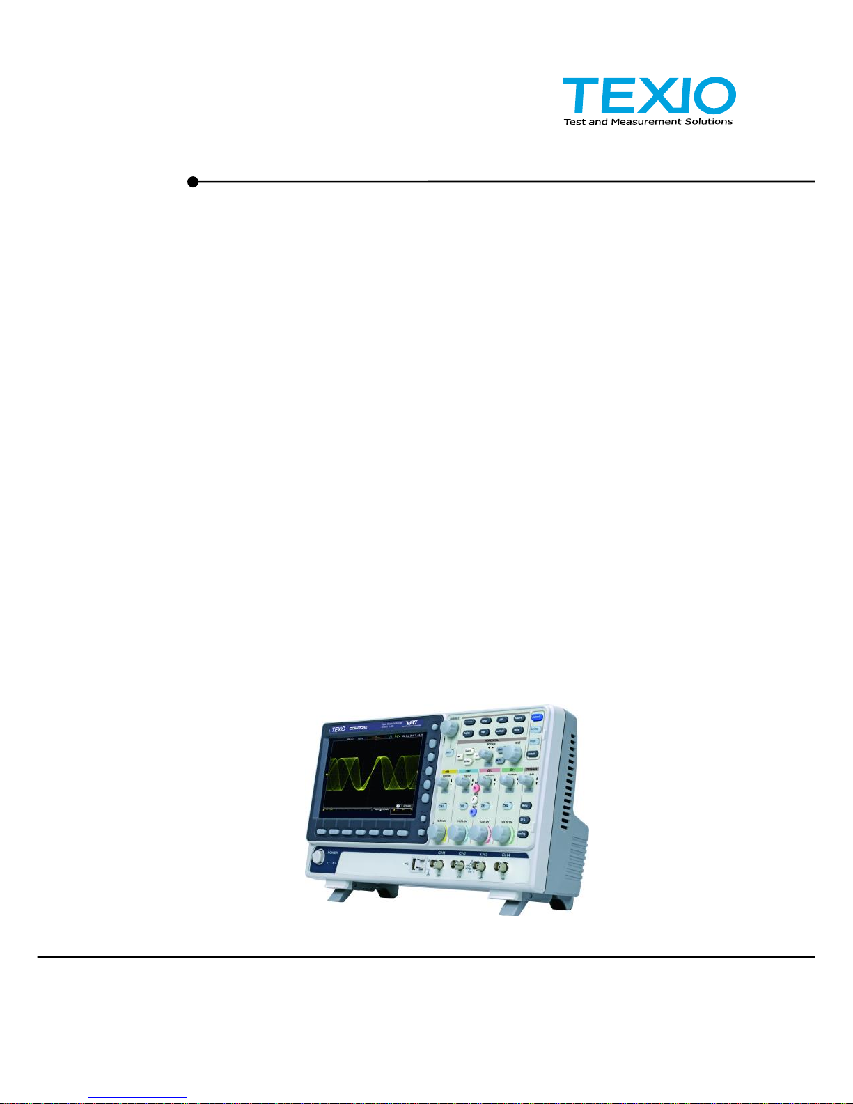
PROGRAMMING MANUAL
DIGITAL STORAGE OSCILLOSCOPE
DCS-2000E SERIES
B71-0461-01

■About a trademark, a registered trademark
A company name and the brand name mentioned in this
instruction manual are the trademark or the registered trademark
of each company or group in each country and region.
■About this instruction manual
When copying the part or all of contents of this instruction manual,
seek the copyright holder.
In addition, the specifications of the product and the contents of
this instruction manual are subject to change without notice for
improvement. Please check to our website for the latest version.

Contents
USING THE PRODUCT SAFELY.............................................................Ⅰ-Ⅴ
1. INTERFACE OVERVIEW ................................................. 1
1-1. Front Panel Overview ........................................................ 1
1-2. Interface Configuration ...................................................... 2
2. COMMAND OVERVIEW .................................................. 9
2-1. Command Syntax .............................................................. 9
3. COMMAND DETAILS..................................................... 10
3-1. Common Commands ......................................................... 11
3-2. Acquisition Commands ...................................................... 16
3-3. Autoscale Commands ....................................................... 21
3-4. Vertical Commands ........................................................... 22
3-5. Math Commands ............................................................... 26
3-6. Cursor Commands ............................................................ 33
3-7. Display Commands ................................ ........................... 41
3-8. Hardcopy Commands ........................................................ 44
3-9. Measure Commands ......................................................... 47
3-10. Measurement Commands ................................................ 68
3-11. Reference Commands ..................................................... 73
3-12. Run Command ................................................................ 75
3-13. Timebase Commands ...................................................... 76
3-14. Trigger Commands ......................................................... 78
3-15. System Commands ....................................................... 109
3-16. Save/Recall Commands ................................................ 110
3-17. Ethernet Commands ..................................................... 113
3-18. Time Commands ........................................................... 113
3-19. Bus Decode Commands ................................................ 114
3-20. Mark Commands ........................................................... 126
3-21. Search Commands ........................................................ 127
3-22. Label Commands ................................ .......................... 154
3-23. Segment Commands ..................................................... 158
3-24. DVM Commands ........................................................... 164
3-25. Go_NoGo Commands ................................................... 166
3-26. Data Logging Commands .............................................. 171
3-27. Remote DiskCommands ................................................ 173
4. APPENDX ................................................................ ....175
4-1. Error messages .............................................................. 175
1
1. INTERFACE OVERVIEW
This manual describes how to use the remote command functionality and
lists the command details. The Overview chapter describes how to
configure the USB remote control interface and Ethernet interface.
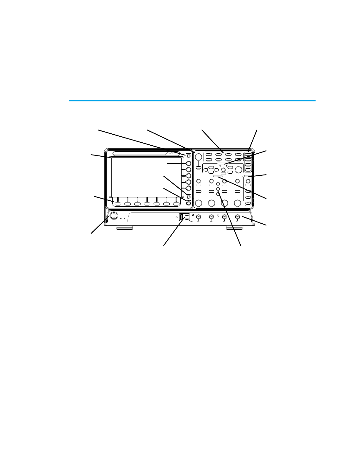
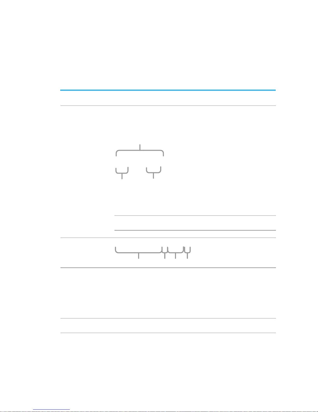
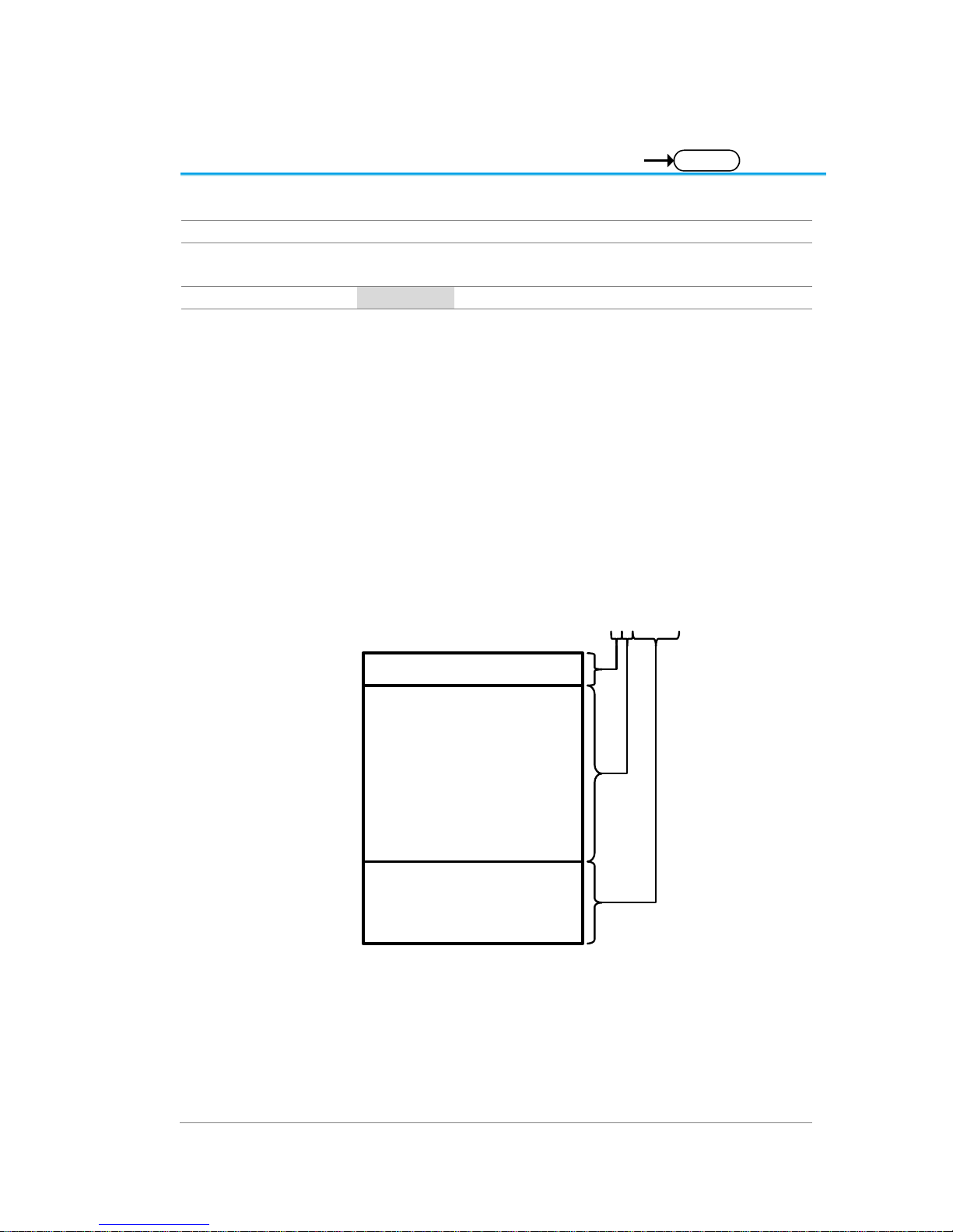
1-1. Front Panel Overview
VARIABLE
POSITION
HORIZONTAL
POSITION
POSITION
POSITION
POSITION
VERTICAL
MATH
REF
BUS
TRIGGER
LEVEL
PUSH TO
ZERO
PUSH TO
ZERO
PUSH TO
ZERO
PUSH TO
ZERO
PUSH TO
ZERO
PUSH TO
ZERO
SCALE
POWER
CH1 CH2 CH3 CH4
2V
1MW16pF
Digital Storage Oscilloscope
200 MHz 1 GS/s
Visual Persistence Oscilloscope
LCD
Variable knob
and Select key
Autoset, Run/Stop, Single
and Default settings
CH1~CH4
Trigger
controls
Function
keys
USB Host port, Probe
Compensation terminals
Power
button
Hardcopy key
Option key
Math, Reference
and Bus keys
Bottom
menu
keys
Horizontal
controls
Menu key
Vertical
controls
Side menu keys
2
1-2. Interface Configuration
1-2-1. Configure USB Interface
USB Configuration
PC side connector
Type A, host
DCS-2000E side
connector
Type B, device
Speed
1.1/2.0 (high speed)
USB Class
USB-CDC
OS
USB Driver
Windows7(32bit/64bit) or higher
TEXIO_CDC*.inf
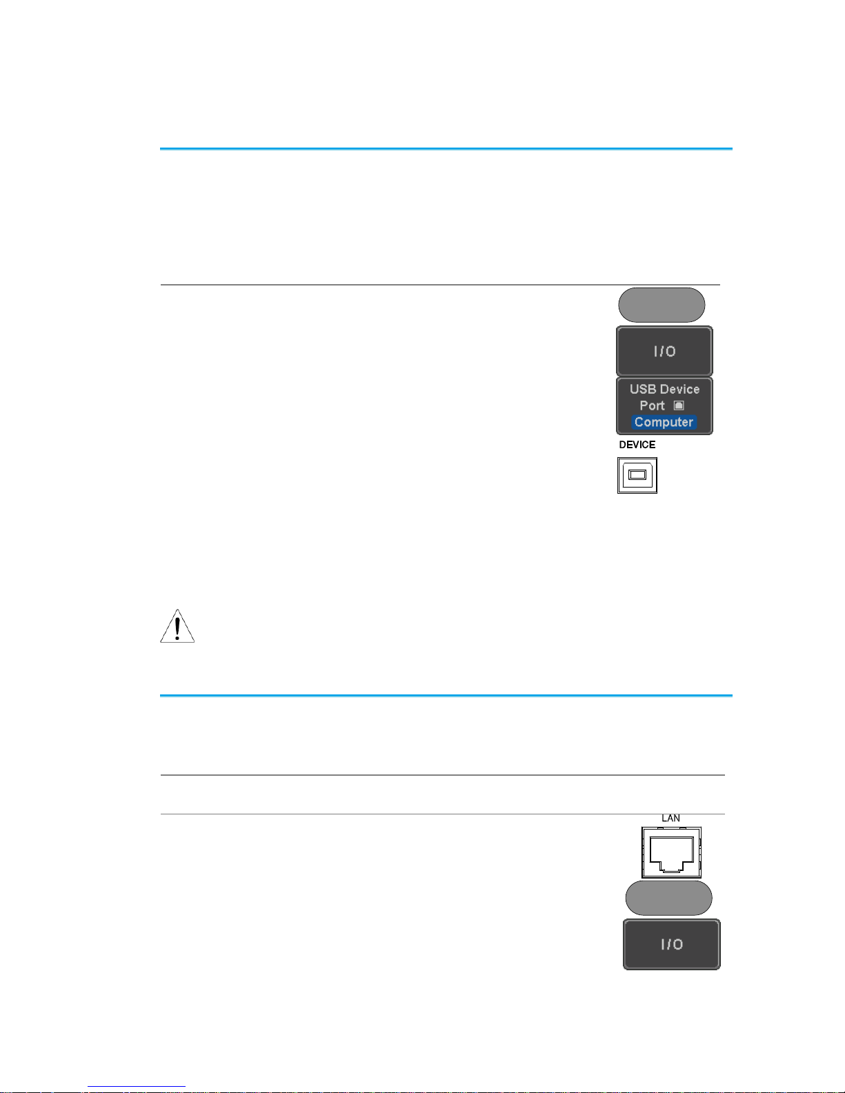
Panel Operation
1. Press the Utility key.
Utility
2. Press I/O from the bottom menu.
3. Press USB Device Port from the side
menu and select Computer.
4. Connect the USB cable to the rear
panel device port.
5. When the PC asks for the USB driver or ‘Unknown
device’ listed in Device Manager, install TEXIOCDC*.inf attached CD.
6. If the computer can not recognize the new hardware
due to the security, please go to update the driver
from the "Other devices" in the Device Manager.
Note
You must have administrator account to install driver.
1-2-2. Configure the Ethernet Interface
Ethernet
Configuration
MAC Address
Domain Name
Instrument Name
DNS IP Address
User Password
Gateway IP Address
Instrument IP Address
Subnet Mask
Background
The Ethernet interface is used for remote control using a
socket server connection.
Panel Operation
1. Connect the Ethernet cable to the LAN
port on the rear panel.
2. Press the Utility key.
Utility
3. Press I/O from the bottom menu.
3
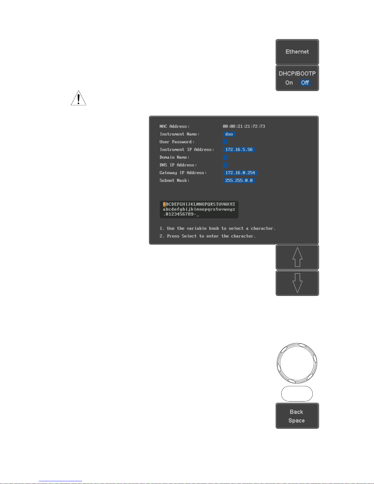
4. Press Ethernet from the side menu.
5. Set DHCP/BOOTP to On or Off from
the side menu.
Note
IP addresses will automatically be assigned with
DHCP/BOOTP set to on. For Static IP Addresses,
DHCP/BOOTP should be set to off.
6. Use the Up and Down arrows on the
side menu to navigate to each Ethernet
configuration item.
Items
MAC Address, Instrument Name, User
Password, Instrument IP Address,
Domain Name, DNS IP Address,
Gateway IP Address, Subnet Mask
7. Use the Variable knob to highlight a
character and use the Select key to
choose a character.
VARIABLE
Select
Press Backspace to delete a
character.
4
Press Save Now to save the
configuration. Complete will be
displayed when successful.
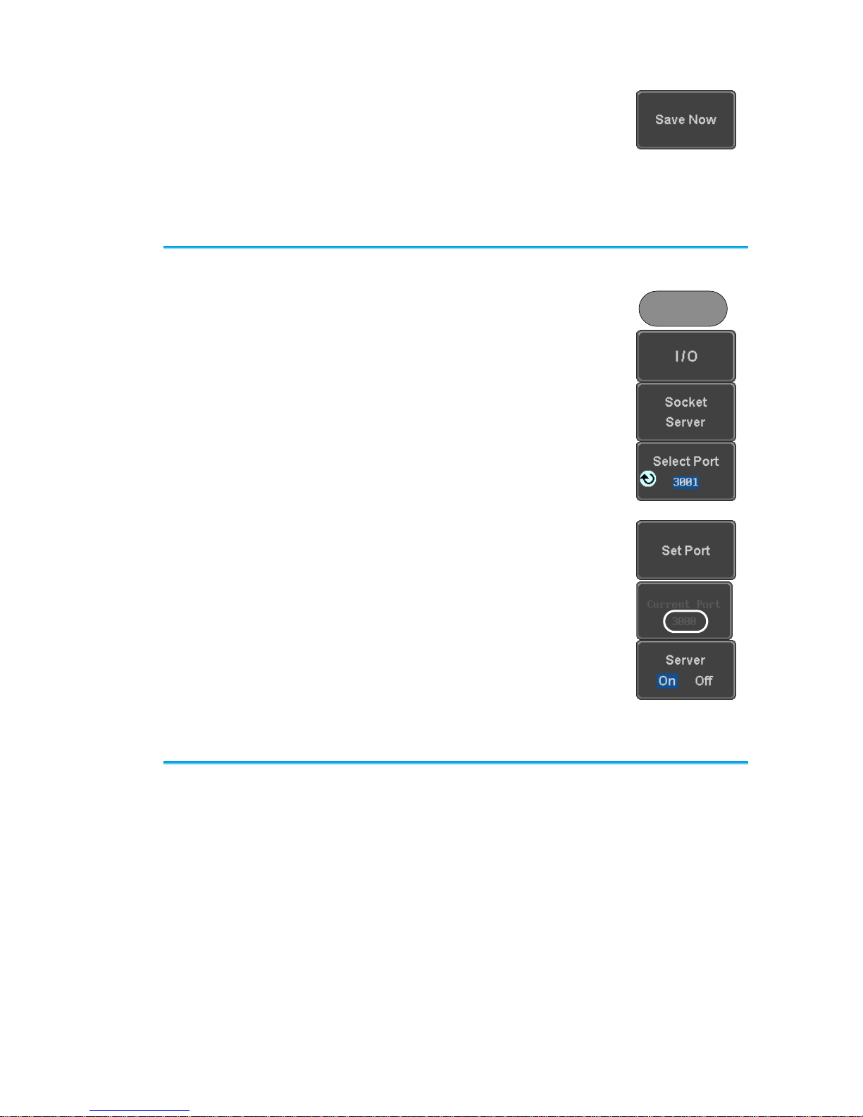
1-2-3. Configure Socket Server
The DCS-2000E supports socket server functionality for direct and full
duplex communication with a client PC or device over LAN. By default, the
Socket Server is off.
Configure Socket
Server
1. Configure the IP address for the DCS2000E.
2. Press the Utility key.
Utility
3. Press I/O from the bottom menu.
4. Press Socket Server from the side
menu.
5. Press Select Port and choose the port
number with the Variable knob.
Range
1024~65535
6. Press Set Port to confirm the port
number.
7. The Current Port icon will update to the
new port number.
8. Press Server and turn the socket
server On.
1-2-4. USB Functionality Check
Terminal
Application (USB)
Invoke the terminal application such as PuTTY or
RealTerm. For USB, set the COM port, baud rate, stop
bit, data bit, and parity accordingly.
To check the COM port number and associated port
settings, see the Device Manager in the PC. For
Windows:
Control panel → Hardware and Sound→ Device
Manager
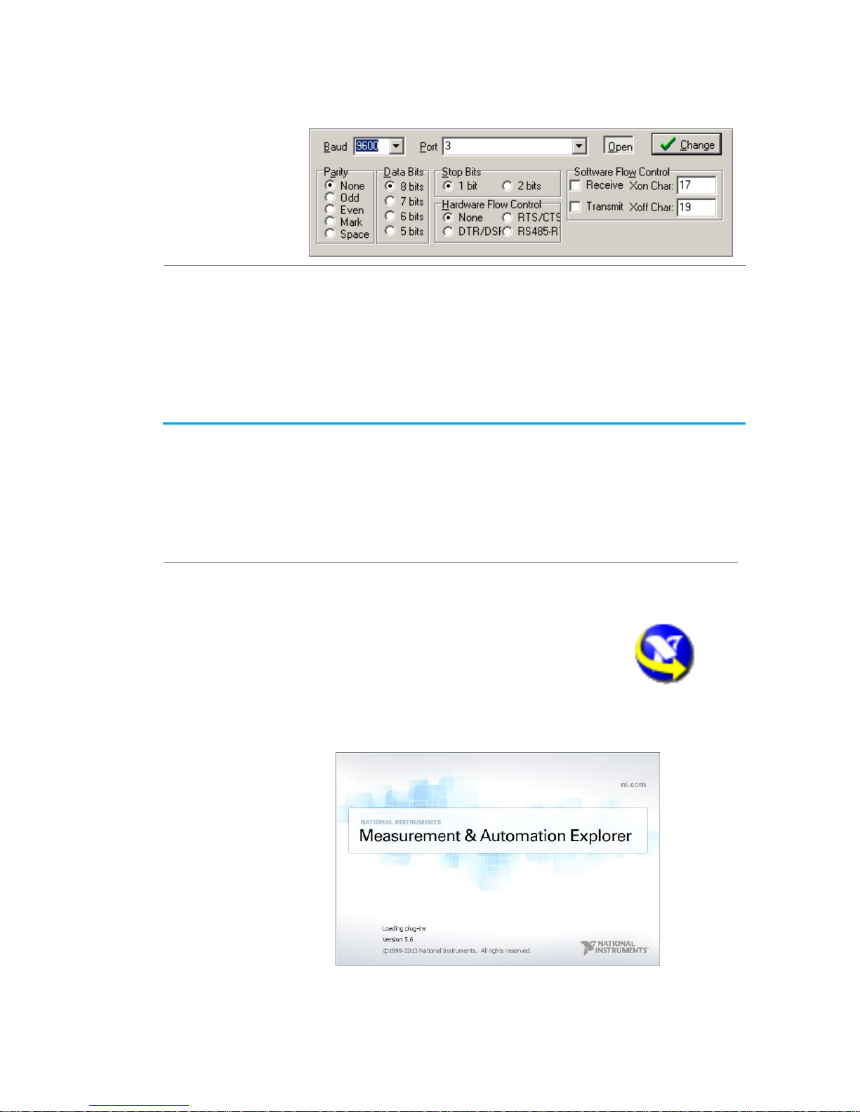
5
Example: Configuring RealTerm for RS-232C
communication.
Functionality
Check
Key in this query command via the terminal application.
*idn?
This should return the Manufacturer, Model number,
Serial number, and Firmware version in the following
format.
TEXIO, DCS-2204E, PXXXXXX, V1.00
1-2-5. Socket Server Functionality Check
NI Measurement
and Automation
Explorer
To test the socket server functionality, National
Instruments MAX (Measurement and Automation
Explorer) can be used. This program is available on the
NI website, www.ni.com.
The following display and operation will differ depending
on the version of MAX, Please use in accordance with
the display for your MAX.
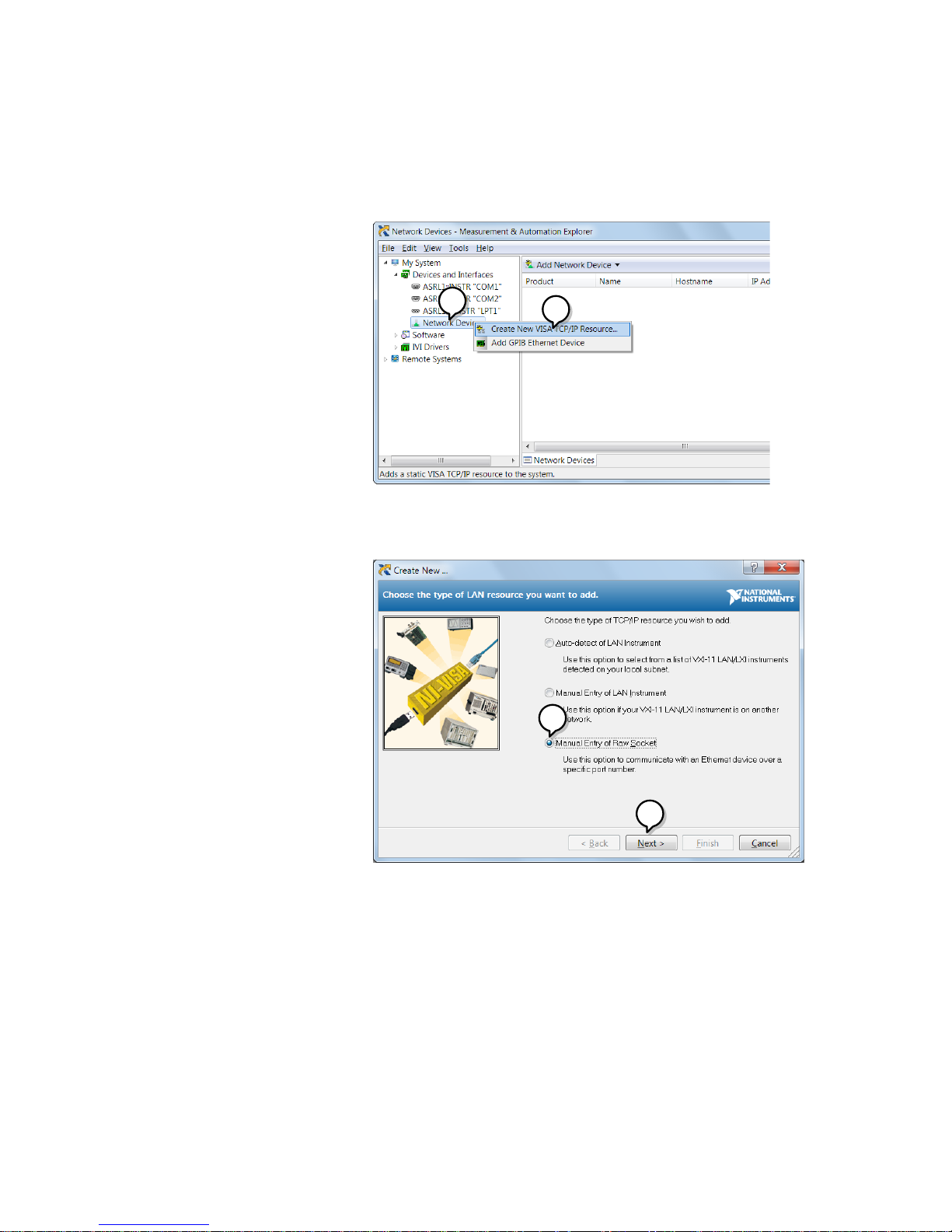
Operation
1. Configure the IP address for the DCS2000E.
2. Configure the socket port.
3. Start the NI Measurement and
Automation Explorer (MAX)
program. Using Windows, press:
Start>All Programs>National
Instruments>Measurement & Automation
6
4. From the Configuration panel access;
My System>Devices and Interfaces>Network
Devices
5. Right click Network Devices and select Create
New Visa TCP/IP Resource…
4
5
6. Select Manual Entry of Raw Socket from the
popup window.
7. Click Next.
6
7
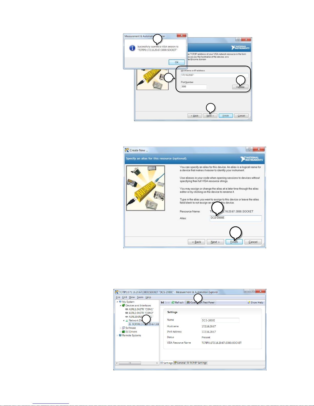
8. Enter the IP address and socket port number of
the DCS-2000E.
9. Click Validate.
10. A popup will appear to tell you if a VISA socket
session was successfully created.
11. Click Next.
7
10
11
8
9
12. Choose an alias for the socket connection if you
like.
13. Click Finish to finish the configuration.
12
13
14. The DCS-2000E will now appear under
Network Devices in the Configuration Panel.
Functionality
Check
15. Click the Open Visa Test Panel to send a
remote command to the DCS-2000E.
14
15
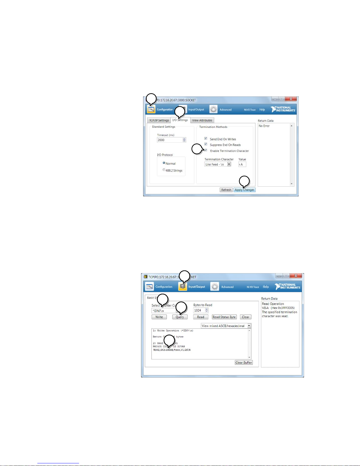
8
16. Click on the Configuration icon.
17. Select the I/O Settings tab.
18. Mark the Enable Termination Character
checkbox. Make sure the termination character
is a line feed (/n, value: xA).
19. Click Apply Changes.
16
17
18
19
20. Click the Input/Output icon.
21. Make sure *IDN? query is selected in the Select
or Enter Command drop box.
22. Click on Query.
23. The manufacturer, model number, serial
number and firmware version will be displayed
in the buffer. For example:
TEXIO,DCS-2202E,PXXXXXX,V1.00
20
21
22
23
9
2. COMMAND OVERVIEW
The Command overview chapter lists all DCS-2000E commands
in functional order as well as alphabetical order. The command
syntax section shows you the basic syntax rules you have to apply
when using commands.
2-1. Command Syntax
Compatible
standard
USB CDC_ACM compatible
SCPI, 1994 (partially compatible)
Command forms
Commands and queries have two different forms, long
and short. The command syntax is written with the short
form of the command in capitals and the remainder (long
form) in lower case.
:TIMebase:SCALe?
Short
Long
Short
The commands can be written in capitals or lower-case,
just so long as the short or long forms are complete. An
incomplete command will not be recognized. Below are
examples of correctly written commands.
LONG
:TIMebase:SCALe?
:TIMEBASE:SCALE?
:timebase:scale?
SHORT
:TIM:SCAL?
:TIM:SCAL?
Command format
:TIMebase:SCALe <NR3>LF
1 2 3 4
1: command header
2: single space
3: parameter
4: message terminator
Parameter
Type
Description
Example
<Boolean>
boolean logic
0, 1
<NR1>
Integers
0, 1, 2, 3
<NR2>
floating point
0.1, 3.14, 8.5
<NR3>
floating point with
an exponent
4.5e-1, 8.25e+1
<NRf>
any of NR1, 2, 3
1, 1.5, 4.5e-1
Message
terminator
LF
line feed code
Note
Commands are non-case sensitive.

10
3. COMMAND DETAILS
The Command details chapter shows the detailed syntax, equivalent
panel operation, and example for each command.
3-1. Common Commands ......................................................... 11
3-2. Acquisition Commands ...................................................... 16
3-3. Autoscale Commands ....................................................... 21
3-4. Vertical Commands ........................................................... 22
3-5. Math Commands ............................................................... 26
3-6. Cursor Commands ............................................................ 33
3-7. Display Commands ........................................................... 41
3-8. Hardcopy Commands ........................................................ 44
3-9. Measure Commands ......................................................... 47
3-10. Measurement Commands ................................................ 68
3-11. Reference Commands ..................................................... 73
3-12. Run Command ................................................................ 75
3-13. Timebase Commands ...................................................... 76
3-14. Trigger Commands ......................................................... 78
3-15. System Commands ....................................................... 109
3-16. Save/Recall Commands ................................................ 110
3-17. Ethernet Commands ..................................................... 113
3-18. Time Commands ........................................................... 113
3-19. Bus Decode Commands ................................................ 114
3-20. Mark Commands ........................................................... 126
3-21. Search Commands ........................................................ 127
3-22. Label Commands .......................................................... 154
3-23. Segment Commands ..................................................... 158
3-24. DVM Commands ........................................................... 164
3-25. Go_NoGo Commands ................................................... 166
3-26. Data Logging Commands .............................................. 171
3-27. Remote DiskCommands ................................................ 173

11
3-1. Common Commands
3-1-1. *IDN? ....................................................................................................... 11
3-1-2. *LRN? ...................................................................................................... 11
3-1-3. *SAV ................................................................ ................................ ........ 11
3-1-4. *RCL ................................ ................................................................ ........ 12
3-1-5. *RST ................................ ................................................................ ........ 12
3-1-6. *CLS ........................................................................................................ 12
3-1-7. *ESE ................................................................ ................................ ........ 12
3-1-8. *ESR ........................................................................................................ 13
3-1-9. *OPC ....................................................................................................... 13
3-1-10. *SRE ...................................................................................................... 14
3-1-11. *STB ...................................................................................................... 15
3-1-1. *IDN?
Query
Description
Returns the manufacturer, model, serial number and
version number of the unit.
Syntax
*IDN?
Example
*IDN?
TEXIO, DCS-2204E,P930116,V0.82b
3-1-2. *LRN?
Query
Description
Returns the oscilloscope settings as a data string.
Syntax
*LRN?
Example
*LRN?
:DISPlay:WAVEform VECTOR;PERSistence 2.400E01;INTensity:WAVEform 50;INTensity:GRATicule
50;GRATicule FULL;:CHANnel CH1:DISPlay ON;BWLimit
・
・
・
1.000e+00;PROBe:TYPe VOLTAGE;SCALe 5.000E-
02;IMPedance 1E+6;EXPand GROUND;:CHANnel OFF
3-1-3. *SAV
Set
Description
Saves the current panel settings to the selected
memory number.
Syntax
*SAV {1 | 2 | 3 |…. | 20}
Example
*SAV 1
Saves the current panel settings to Set 1
12
3-1-4. *RCL
Set
Description
Recalls a set of panel settings.
Syntax
*RCL {1 | 2 | 3 |…. | 20}
Example
*RCL 1
Recalls the selected setup from Set 1.
3-1-5. *RST
Set
Description
Resets the DCS-2000E (recalls the default panel
settings).
Syntax
*RST
3-1-6. *CLS
Set
Description
Clears the error queue.
Syntax
*CLS
3-1-7. *ESE
Set
Query
Description
Sets or queries the Standard Event Status Enable
register.
Syntax
Query Syntax
*ESE <NR1>
*ESE?
Return parameter
<NR1>
0~255
Bit Weight
Bit#
Weight
Event
Description
0 1 OPC
Operation Complete Bit
1 2 RQC
Not used
2 4 QYE
Query Error
3 8 DDE
Device Error
4
16
EXE
Execution Error
5
32
CME
Command Error
6
64
URQ
User Request
7
128
PON
Power On
Example
*ESE?
>4
Indicates that there is a query error.

13
3-1-8. *ESR
Query
Description
Queries the Standard Event Status (Event) register.
The Event Status register is cleared after it is read.
Query Syntax
*ESR?
Return parameter
<NR1>
0~255
Bit Weight
Bit#
Weight
Event
Description
0 1 OPC
Operation Complete Bit
1 2 RQC
Not used
2 4 QYE
Query Error
3 8 DDE
Device Error
4
16
EXE
Execution Error
5
32
CME
Command Error
6
64
URQ
User Request
7
128
PON
Power On
Example
*ESR?
>4
Indicates that there is a query error.
3-1-9. *OPC
Set
Query
Description
The *OPC command sets the OPC bit (bit0) of the
Standard Event Status Register when all current
commands have been processed.
The *OPC? Query returns 1 when all the outstanding
commands have completed.
Syntax
Query Syntax
*OPC
*OPC?
Return parameter
1
Returns 1 when all the outstanding
commands have completed.

14
3-1-10. *SRE
Set
Query
Description
Sets or queries the Service Request Enable register.
The Service Request Enable register determines which
registers of the Status Byte register are able to
generate service requests.
Syntax
Query Syntax
*SRE <NR1>
*SRE?
Parameter/
Return parameter
<NR1>
0~255
Bit Weight
Bit#
Weight
Event
Description
0 1
Not used
1 2
Not used
2 4
Not used
3 8
Not used
4
16
MAV
Message Available Bit
5
32
ESB
Event Status Bit
6
64
MSS
Master Summary Bit
6
64
RQS
Request Service Bit
7
128
Not used
Example
*SRE?
>48
Indicates that the MAVB and ESB bit are both set.

15
3-1-11. *STB
Query
Description
Queries the bit sum of the Status Byte register with
MSS (Master summary Status) replacing the RQS bit
(bit 6).
Query Syntax
*STB?
Return parameter
<NR1>
0 ~ 255
Bit Weight
Bit#
Weight
Event
Description
0 1
Not used
1 2
Not used
2 4
Not used
3 8
Not used
4
16
MAV
Message Available Bit
5
32
ESB
Event Status Bit
6
64
MSS
Master Summary Bit
6
64
RQS
Request Service Bit
7
128
Not used
Example
*STB?
>16
Indicates that the MAV bit is set.
16
3-2. Acquisition Commands
3-2-1. :ACQuire:AVERage.................................................................................. 16
3-2-2. :ACQuire:MODe ....................................................................................... 16
3-2-3. :ACQuire<X>:MEMory? ........................................................................... 17
3-2-4. :ACQuire:FILTer:SOURce ........................................................................ 18
3-2-5. :ACQuire:FILTer ....................................................................................... 19
3-2-6. :ACQuire:FILTer:FREQuency .................................................................. 19
3-2-7. :ACQuire:FILTer:TRACking ...................................................................... 19
3-2-8. :ACQuire<X>:STATe? .............................................................................. 20
3-2-9. :ACQuire:RECOrdlength .......................................................................... 20
3-2-10. :HEADer................................................................................................. 21
3-2-1. :ACQuire:AVERage
Set
Query
Description
Selects or returns the number of waveform acquisitions
that are averaged in the average acquisition mode.
Syntax
:ACQuire:AVERage {<NR1>| ?}
Related Commands
:ACQuire:MODe
Parameter
<NR1>
2, 4, 8 ,16, 32, 64, 128, 256
Note
Before using this command, select the average
acquisition mode. See the example below.
Example
:ACQuire:MODe AVERage
:ACQuire:AVERage 2
Selects the average acquisition mode, and sets the
average number to 2.
3-2-2. :ACQuire:MODe
Set
Query
Description
Selects or returns the acquisition mode.
Syntax
:ACQuire:MODe {SAMPle | PDETect | AVERage | ?}
Related Commands
:ACQuire:AVERage
Parameter
SAMPle
Sample mode sampling
PDETect
Peak detect sampling
AVERage
Average sampling mode
Example
:ACQuire:MODe PDETect
Sets the sampling mode to peak detection.
17
3-2-3. :ACQuire<X>:MEMory?
Query
Description
Returns the data in acquisition memory for the
selected channel as a header + raw data.
Syntax
:ACQuire<X>:MEMory?
Related Commands
ACQuire:RECOrdlength
:HEADer
Parameter
<X>
Channel number (1 to 4)
Return parameter
Returns acquisition settings followed by raw waveform
block data.
<string>
Returns the acquisition settings for the selected
channel.
Format:
parameter(1),setting(1);parameter(2),setting(2)…para
meter(n),setting(n);Waveform Data;
<waveform block data>
Header followed by the raw waveform data.
Format:
Header: The header (in ASCII) encodes the number of
bytes for the header followed by the number of data
points in bytes for the raw data.
#42000
Header identifier
Indicates the number
of characters that will
encode the number of
data points (ie. 2000
= 4 characters) after
which the raw data
will follow.
Indicates the number
of bytes that follow
(for the raw data).
ASCII
Raw Data:
Each two bytes (in hex) encodes the vertical data of a
data point. The data is signed hex data (2’s
complement, -32768 ~ 32767).
Waveform Raw Data Example:
Header raw data……….
Hex:
23 34 32 30 30 30 00 1C 00 1B 00 1A 00 1A 00 1B
18
………..
ASCII/Decimal:
#42000 28 27 26 26 27…….
The actual value of a data point can be calculated with
the following formula:
(Decimal value of hex data/AD Factor) * vertical scale.
Note: AD Factor is fixed as 25. The vertical scale is
returned with the acquisition settings that precede the
raw data.
For example if the raw data for a point is 001C (=28
decimal) then,
(28/25) x 0.5 = 0.56V
Example
:ACQuire1:MEMory?
Format,2.0E;Memory Length,10000;IntpDistance,0;
Trigger Address,4999;Trigger Level,1.160E+01;
Source,CH1;Vertical Units,V;Vertical Units
Div,0;Vertical Units Extend Div,15;Label,ACK ;Probe
Type,0;Probe Ratio,1.000e+01;Vertical
Scale,5.000e+00;Vertical Position,-
1.100e+01;Horizontal Units,S;Horizontal Scale,5.000E-
04;Horizontal Position,0.000E+00; Horizontal
Mode,Main;SincET Mode,Real Time;Sampling
Period,5.000e-07;Horizontal Old Scale,5.000E04;Horizontal Old Position,0.000E+00;
Firmware,V0.99b8;Time,02-Oct-14 17:00:43;
Waveform Data; #520000…follows waveform block
data in hex…………………..
Note:
On Windows 10, data loss may occur due to
insufficient CPU power. Adjust the transfer timing with
the ":USBDelay" command and use as fast a PC as
possible.
3-2-4. :ACQuire:FILTer:SOURce
Set
Query
Description
Returns the source of the filter.
Syntax
:ACQuire:FILTer:SOURce {CH1|CH2|CH3|CH4|?}
Parameter/
Return parameter
CH1 ~ CH4
Source channel
Example
:ACQuire:FILTer:SOURce?
CH1
Sets the filter source to CH1.
19
3-2-5. :ACQuire:FILTer
Set
Query
Description
Turns the filter on/off or queries its status.
Syntax
:ACQuire:FILTer {OFF | ON | ?}
Parameter/Return
parameter
OFF
Turns the digital filter off.
ON
Turns the digital filter on.
Example
:ACQuire:FILTer OFF
Turns the digital filter off.
3-2-6. :ACQuire:FILTer:FREQuency
Set
Query
Description
Sets or queries the filter frequency.
Syntax
:ACQuire:FILTer:FREQuency {DEFault|<NRf>|?}
Parameter/ Return
parameter
DEFault
Sets the filter frequency to the default.
<NRf>
Manually sets the filter frequency.
(1Hz ~ 500MHz)
Example
:ACQuire:FILTer:FREQuency 1
Sets the filter frequency to 1Hz.
3-2-7. :ACQuire:FILTer:TRACking
Set
Query
Description
Turns filter tracking on/off or queries its state.
Syntax
:ACQuire:FILTer:TRACking {ON|OFF|?}
Parameter/ Return
parameter
OFF
Tracking off
ON
Tracking on
Example
:ACQuire:FILTer:TRACking ON
Turns filter tracking on.
20
3-2-8. :ACQuire<X>:STATe?
Query
Description
Returns the status of waveform data.
Syntax
:ACQuire<X>:STATe?
Parameter
<X>
Channel number (1 to 4)
Return parameter
0
Raw data is not ready
1 Raw data is ready
Example
:ACQuire1:STATe?
0
Returns 0. The channel 1’s raw data is not ready.
Note: If the oscilloscope changes the acquisition status
from STOP to RUN, the status will be reset as zero.
3-2-9. :ACQuire:RECOrdlength
Set
Query
Description
Sets or queries the record length. Please see the user
manual for full details.
Syntax
:ACQuire:RECOrdlength {<NRf>| ?}
Parameter/Return
parameter
<NRf>
Record length. Settable record length: (1e+3 |
1e+4 | 1e+5 | 1e+6 | 1e+7)
Example
:ACQuire:RECOrdlength 1e+3
Sets the record length to 1000 points.
21
3-2-10. :HEADer
Set
Query
Description
Configures whether the :ACQuire:MEM
or :ACQuire:LMEM return data will contain header
information or not. It is set to ON by default.
Syntax
:HEADer {OFF | ON | ?}
Related Commands
:ACQuire<X>:MEMory?
Parameter
<X>
Channel number (1 to 4)
ON
Add header information.
OFF
Don’t add header information.
Return parameter
Returns the configuration (ON, OFF) for the selected
channel.
Example
:HEADer ON
3-3. Autoscale Commands
3-3-1. :AUTOSet
Set
Description
Runs the Autoset function to automatically configure
the horizontal scale, vertical scale, and trigger
according to the input signal.
Syntax
:AUTOSet
3-3-2. :AUTORSET:MODe
Set
Query
Description
Sets the Autoset mode or queries its state.
Syntax
:AUTORSET:MODe {FITScreen | ACPriority | ?}
Related Commands
:AUTOSet
Parameter/Return
parameter
FITScreen
Fit Screen mode
ACPriority
AC priority mode
Example
:AUTORSET?
FITSCREEN
22
3-4. Vertical Commands
3-4-1. :CHANnel<X>:BWLimit ................................................................ ............ 22
3-4-2. :CHANnel<X>:COUPling .......................................................................... 22
3-4-3. :CHANnel<X>:DESKew ........................................................................... 23
3-4-4. :CHANnel<X>:DISPlay ............................................................................. 23
3-4-5. :CHANnel<X>:EXPand ............................................................................ 23
3-4-6. :CHANnel<X>:IMPedance? ...................................................................... 24
3-4-7. :CHANnel<X>:INVert ............................................................................... 24
3-4-8. :CHANnel<X>:POSition ........................................................................... 24
3-4-9. :CHANnel<X>:PROBe:RATio ................................................................... 25
3-4-10. :CHANnel<X>:PROBe:TYPe ................................................................ .. 25
3-4-11. :CHANnel<X>:SCALe ............................................................................ 25
3-4-1. :CHANnel<X>:BWLimit
Set
Query
Description
Sets or returns the bandwidth limit on/off.
Syntax
:CHANnel<X>:BWLimit {FULL | <NR3> | ?}
Parameter
<X>
Channel 1,2,3,4
FULL
Full bandwidth
<NR3>
Sets the bandwidth limit to a pre-defined
bandwidth.
100E+6: 100MHz
20E+6: 20MHz
Return Parameter
<NR3>
Returns the bandwidth.
Full
Full bandwidth
Example
:CHANnel1:BWLimit 2.000E+07
Sets the channel 1 bandwidth 20MHz
3-4-2. :CHANnel<X>:COUPling
Set
Query
Description
Selects or returns the coupling mode.
Syntax
CHANnel<X>:COUPling {AC | DC | GND | ?}
Parameter
<X>
Channel 1,2,3,4
AC
AC coupling
DC
DC coupling
GND
Ground coupling
Return parameter
Returns the coupling mode.
Example
:CHANnel1:COUPling DC
Sets the coupling to DC for Channel 1.
23
3-4-3. :CHANnel<X>:DESKew
Set
Query
Description
Sets the deskew time in seconds.
Syntax
:CHANnel<X>:DESKew { <NR3> | ?}
Parameter
<X>
Channel 1,2,3,4
<NR3>
Deskew time:
-5.00E -11 to 5.00E-11
-50ns to 50 ns.
Return parameter
<NR3>
Returns the deskew time.
Example
:CHANnel1:DESKew 1.300E-9
Sets the deskew time to 1.3 nano seconds.
3-4-4. :CHANnel<X>:DISPlay
Set
Query
Description
Turns a channel on/off or returns its status.
Syntax
:CHANnel<X>:DISPlay {OFF | ON | ?}
Parameter
<X>
Channel 1,2,3,4
OFF
Channel off
ON
Channel on
Return Parameter
ON
Channel is on.
OFF
Channel is off
Example
:CHANnel1:DISPlay ON
Turns on Channel 1
3-4-5. :CHANnel<X>:EXPand
Set
Query
Description
Sets Expand By Ground or Expand By Center for a
channel or queries its status.
Syntax
:CHANnel<X>:EXPand {GND | CENTer | ?}
Parameter
<X>
Channel 1,2,3,4
GND
Ground
CENTer
Center
Return parameter
GND
Expand By Ground
CENTER
Expand By Center
Example
:CHANnel1:EXPand GND
Sets Channel 1 to Expand By Ground.
24
3-4-6. :CHANnel<X>:IMPedance?
Query
Description
Returns the impedance of the oscilloscope.
Syntax
:CHANnel<X>:IMPedance?
Parameter
<x>
Channel
1/2/3/4
CH1/2/3/4
Return parameter
<NR3>
Returns the impedance value.
Example
:CHANnel1:IMPedance?
1.000000E+06
The impedance is 1M ohms.
3-4-7. :CHANnel<X>:INVert
Set
Query
Description
Inverts a channel or returns its status.
Syntax
:CHANnel<X>:INVert {OFF | ON | ?}
Parameter
<X>
Channel 1, 2, 3, 4
OFF
Invert off
ON
Invert on
Return parameter
ON
Invert on
OFF
Invert off
Example
:CHANnel1:INVert ON
Inverts Channel 1
3-4-8. :CHANnel<X>:POSition
Set
Query
Description
Sets or returns the position level for a channel.
Note
The vertical position will only be set to closest allowed
value. The position level range depends on the vertical
scale.
The scale must first be set before the position can be
set.
Syntax
:CHANnel<X>:POSition { <NRf> | ?}
Parameter
<X>
Channel 1, 2, 3, 4
<NRf>
Position. Range depends on the vertical scale.
Return parameter
<NR3>
Returns the position value.
Example 1
:CHANnel1:POSition 2.4E–3
Sets the Channel 1 position to 2.4mV/mA
Example 2
:CHANnel1:POSition?
2.4E-3
Returns 2.4mV as the vertical position.
25
3-4-9. :CHANnel<X>:PROBe:RATio
Set
Query
Description
Sets or returns the probe attenuation factor.
Syntax
:CHANnel<X>:PROBe:RATio { <NRf> | ?}
Related Commands
:CHANnel<X>:PROBe:TYPe
Parameter
<X>
Channel 1, 2, 3, 4
<NRf>
Probe attenuation factor.
Return parameter
<NR3>
Returns the probe factor.
Example
:CHANnel1:PROBe:RATio 1.00E+0
Sets the Channel 1 probe attenuation factor to 1x
3-4-10. :CHANnel<X>:PROBe:TYPe
Set
Query
Description
Sets or returns the probe type (voltage/current).
Syntax
:CHANnel<X>:PROBe:TYPe { VOLTage | CURRent
| ?}
Related Commands
:CHANnel<X>:PROBe:RATio
Parameter
<X>
Channel 1, 2, 3, 4
VOLTage
Voltage
CURRent
Current
Return parameter
Returns the probe type.
Example
:CHANnel1:PROBe:TYPe VOLTage
Sets the Channel 1 probe type to voltage.
3-4-11. :CHANnel<X>:SCALe
Set
Query
Description
Sets or returns the vertical scale. The scale depends
on the probe attenuation factor.
Note the probe attenuation factor should be set before
the scale.
Syntax
:CHANnel<X>:SCALe { <NRf> | ?}
Parameter
<X>
Channel 1, 2, 3, 4
<NRf>
Vertical scale:
2e–3 to 1e+1
2mV to 10V (Probe x1)
Return parameter
<NR3>
Returns the vertical scale in volts or amps.
Example
:CHANnel1:SCAle 2.00E–2
Sets the Channel 1 vertical scale to 20mV/div
26
3-5. Math Commands
3-5-1. :MATH:DISP ............................................................................................ 26
3-5-2. :MATH:TYPe ............................................................................................ 26
3-5-3. :MATH:DUAL:SOURce<X> ...................................................................... 27
3-5-4. :MATH:DUAL:OPERator .......................................................................... 27
3-5-5. :MATH:DUAL:POSition ................................................................ ............ 27
3-5-6. :MATH:DUAL:SCALe ............................................................................... 28
3-5-7. :MATH:FFT:SOURce ............................................................................... 28
3-5-8. :MATH:FFT:MAG ..................................................................................... 28
3-5-9. :MATH:FFT:WINDow ............................................................................... 29
3-5-10. :MATH:FFT:POSition ............................................................................. 29
3-5-11. :MATH:FFT:SCALe ................................................................................ 29
3-5-12. :MATH:FFT:HORizontal:SCALe ............................................................. 30
3-5-13. :MATH:FFT:HORizontal:POSition .......................................................... 30
3-5-14. :MATH:DEFine ....................................................................................... 31
3-5-15. :MATHVAR? .......................................................................................... 31
3-5-16. :MATHVAR:VAR<X> .............................................................................. 32
3-5-17. :MATH:ADVanced:POSition ................................................................ ... 32
3-5-18. :MATH:ADVanced:SCALe ...................................................................... 32
3-5-1. :MATH:DISP
Set
Query
Description
Turns the math display on or off on the screen.
Syntax
:MATH:DISP {OFF|ON|?}
Parameter/ Return
parameter
OFF
Math is not displayed on screen
ON
Math is displayed on screen
Example
:MATH:DISP OFF
Math is off.
3-5-2. :MATH:TYPe
Set
Query
Description
Queries or sets the Math type to FFT, Advanced Math
or to dual channel math operations
Syntax
:MATH:TYPe { DUAL | ADVanced | FFT | ? }
Related Commands
:MATH:DISP
Parameter
DUAL
Dual channel operations
ADVanced
Advanced math operations
FFT
FFT operations
Return parameter
Returns the math type.
Example
:MATH:TYPe DUAL
Sets the Math type to dual channel math operation.
27
3-5-3. :MATH:DUAL:SOURce<X>
Set
Query
Description
Sets the dual math source for source 1 or 2.
Syntax
:MATH:DUAL:SOURce<X> { CH1 | CH2 | CH3 | CH4 |
REF1 | REF2 | REF3 | REF4 | ? }
Parameter
<X>
Source number 1 or 2
CH1~4
Channel 1 to 4
REF1~4
Reference waveforms 1 to 4
Return parameter
Returns the source for the source 1 or 2.
Example
:MATH:DUAL:SOURce1 CH1
Sets source1 as channel 1.
3-5-4. :MATH:DUAL:OPERator
Set
Query
Description
Sets the math operator for dual math operations.
Syntax
:MATH:DUAL:OPERator {PLUS | MINUS | MUL| DIV|?}
Parameter
PLUS
+ operator
MINUS
- operator
MUL
operator
DIV
÷ operator
Return parameter
Returns operator type.
Example
:MATH:DUAL:OPERator PLUS
Sets the math operator as plus (+).
3-5-5. :MATH:DUAL:POSition
Set
Query
Description
Sets the vertical position of the displayed math result
expressed by division.
Syntax
:MATH:DUAL:POSition {<NRf> | ? }
Parameter
<NRf>
Vertical position
Depends on the vertical scale (Unit/Div)
Return parameter
<NR3>
Returns the vertical position.
Example
:MATH:DUAL:POSition 1.0E+0
Sets the vertical position to 1.00 unit/div.

28
3-5-6. :MATH:DUAL:SCALe
Set
Query
Description
Sets the vertical scale of the displayed math result.
Syntax
:MA TH:DUAL:SCALe {<NRf> | ?}
Parameter
<NRf>
Vertical scale
Return parameter
<NR3>
Returns the scale.
Example
:MATH:DUAL:SCALe 2.0E-3
Sets the vertical scale to 2mV/2mA.
3-5-7. :MATH:FFT:SOURce
Set
Query
Description
Sets and queries the FFT math source.
Syntax
:MATH:FFT:SOURce { CH1 | CH2 | CH3 | CH4 | REF1
| REF2 | REF3 | REF4 | FUNCtion | ? }
Related commands
:MATH:ADVanced:EDIT:SOURce<X>
:MATH:ADVanced:EDIT:OPERator
Parameter
CH1~4
Channel 1 to 4
REF1~4
Reference waveform 1 to 4
FUNCtion
F(X) waveform
Return parameter
Returns the FFT source.
Example
:MATH:FFT:SOURce CH1
Sets the FFT math source as channel 1.
3-5-8. :MATH:FFT:MAG
Set
Query
Description
Sets FFT vertical units as linear or decibels.
Syntax
:MATH:FFT:MAG {LINEAR | DB | ?}
Parameter
LINEAR
Linear units (Vrms)
DB
Logarithmic units (dB)
Return parameter
Returns the FFT vertical units.
Example
:MATH:FFT:MAG DB
Sets FFT vertical units to dB.

29
3-5-9. :MATH:FFT:WINDow
Set
Query
Description
Sets the windowing filter used for the FFT function.
Syntax
:MATH:FFT:WINDow
{RECTangular|HAMming|HANning|BLAckman|?}
Parameter
RECTangular
Rectangular window
HAMming
Hamming window
HANning
Hanning window
BLAckman
Blackman window
Return parameter
Returns the FFT window.
Example
:MATH:FFT:WINDow HAMming
Sets the FFT window filter to hamming.
3-5-10. :MATH:FFT:POSition
Set
Query
Description
Sets the vertical position of the displayed FFT result.
Syntax
MATH:FFT:POSition { <NRf> | ? }
Parameter
<NRf>
Vertical position: -12e+0 to +12e+0
(12 units/division to +12 units/division.)
Return parameter
<NR3>
Returns the vertical position.
Example
:MATH:FFT:POSition -2e-1
Sets the FFT position to -0.2 divisions.
3-5-11. :MATH:FFT:SCALe
Set
Query
Description
Sets the vertical scale of the displayed FFT result.
Syntax
:MATH:FFT:SCALe {<NRf> | ?}
Parameter
<NRf>
Vertical scale:
Linear: 2e-3 to 1e+ (32mV~1kV)
dB: 1e+0 to 2e+1 (1~20dB)
Return parameter
<NR3>
Returns vertical scale.
Example
:MATH:FFT:SCAle 1.0e+0
Sets the scale to 1dB.

30
3-5-12. :MATH:FFT:HORizontal:SCALe
Set
Query
Description
Sets or queries the zoom scale for FFT math.
Syntax
:MATH:FFT:HORizonatal:SCALe {<NRf> | ?}
Parameter
<NRf>
Zoom scale: 1 to 20 times
Return parameter
<NR3>
Returns zoom scale.
Example
:MATH:FFT:HORizontal:SCALe 5
Sets the zoom scale to 5X.
3-5-13. :MATH:FFT:HORizontal:POSition
Set
Query
Description
Sets the horizontal position of the displayed FFT result.
Syntax
MATH:FFT:HORizontal:POSition { <NRf> | ? }
Parameter
<NRf>
Horizontal position: 0Hz ~ 999.9kHz
Return parameter
<NR3>
Returns the vertical position.
Example
:MATH:FFT:HORizontal:POSition 6.0e5
Sets the FFT horizontal position to 600kHz.

31
3-5-14. :MATH:DEFine
Set
Query
Description
Sets or queries the advanced math expression as a
string.
Syntax
:MATH:DEFine {<string>| ?}
Related
:MATH:DISP
:MATH:TYPe
Parameter
<string>
An expression enclosed in double quotes.
Note, ensure parentheses are used correctly
in the expression. The expression can contain
the following parts:
Source
CH1~CH4, Ref1~Ref4
Function
Intg(, Diff(, log(, ln(, Exp(, Sqrt(,
Abs(, Rad(, Deg(, sin(, cos(, tan(,
asin(, acos(, atan(
Variable
VAR1, VAR2
Operator
+, -, *, /, (, ), !(, <, >, <=, >=, ==, !=,
||, &&
Figure
0, 1, 2, 3, 4, 5, 6, 7, 8, 9, ., E
Measurement
Pk-Pk(, Max(, Min(, Amp(, High(,
Low(, Mean(, CycleMean(, RMS(,
CycleRMS(, Area(, CycleArea(,
ROVShoot(, FOVShoot(, Freq(,
Period(, Rise(, Fall(, PosWidth(,
NegWidth(, Dutycycle(, FRR(,
FRF(, FFR(, FFF(, LRR(, LRF(,
LFR(, LFF(, Phase(
Return parameter
Returns the expression as a string.
Example
:MATH:DISP ON
:MATH:TYPe ADVanced
:MATH:DEFine "CH1-CH2"
Sets the math expression to CH1-CH2.
3-5-15. :MATHVAR?
Query
Description
Returns the value of the VAR1 and VAR2 variables.
Syntax
:MATHVAR?
Related
Commands
:MATHVAR:VAR<X>
:MATH:DEFine
Return parameter
<string>
VAR1 <NR3>; VAR2 <NR3>
Example
:MATHVAR?
VAR1 1.000000E+06; VAR2 1.0E+1
Returns the value of both variables.

32
3-5-16. :MATHVAR:VAR<X>
Set
Query
Description
Sets or returns the VAR1 or VAR2 variables.
Syntax
:MATHVAR:VAR<x> {<NRf> | ?}
Related
Commands
:MATH:DEFine
Parameter
<X>
1, 2 (VAR1 or VAR2)
<NRf>
Value of VAR1/VAR2
Return parameter
<NR3>
Returns the value of VAR1/VAR2
Example
:MATHVAR:VAR1 6.0e4
Sets VAR1 to 60000.
3-5-17. :MATH:ADVanced:POSition
Set
Query
Description
Sets the vertical position of the advanced math result,
expressed in unit/div.
Syntax
:MATH:ADVanced:POSition { <NRf> | ? }
Parameter
<NRf>
Vertical position: -12e+0 to +12e+0
(12 units/division to +12 units/division.)
Return parameter
<NR3>
Returns the vertical position.
Example
:MATH:ADVanced:POSition 1.0e+0
Sets the position as 1.00 unit/div.
3-5-18. :MATH:ADVanced:SCALe
Set
Query
Description
Sets or queries the vertical scale the advanced math
result.
Syntax
:MATH:ADVanced:SCALe {<NRf> | ?}
Parameter
<NRf>
Vertical scale
Return parameter
<NR3>
Returns the vertical scale.
Example
:MATH:ADVanced:SCALe 2.0E-3
Sets the vertical scale to 2mV/S

33
3-6. Cursor Commands
3-6-1. :CURSor:MODe ....................................................................................... 33
3-6-2. :CURSor:SOURce ................................................................................... 34
3-6-3. :CURSor:HUNI ......................................................................................... 34
3-6-4. :CURSor:HUSE ........................................................................................ 34
3-6-5. :CURSor:VUNI ......................................................................................... 35
3-6-6. :CURSor:VUSE ........................................................................................ 35
3-6-7. :CURSor:DDT .......................................................................................... 35
3-6-8. :CURSor:H1Position ................................................................................ 36
3-6-9. :CURSor:H2Position ................................................................................ 36
3-6-10. :CURSor:HDELta ................................................................................... 36
3-6-11. :CURSor:V1Position ............................................................................... 37
3-6-12. :CURSor:V2Position ............................................................................... 37
3-6-13. :CURSor:VDELta ................................................................................... 37
3-6-14. :CURSor:XY:RECTangular:X:POSition<X> ............................................ 38
3-6-15. :CURSor:XY:RECTangular:X:DELta ...................................................... 38
3-6-16. :CURSor:XY:RECTangular:Y:POSition<X> ............................................ 38
3-6-17. :CURSor:XY:RECTangular:Y:DELta ...................................................... 39
3-6-18. :CURSor:XY:POLar:RADIUS:POSition<X> ............................................ 39
3-6-19. :CURSor:XY:POLar:RADIUS:DELta ....................................................... 39
3-6-20. :CURSor:XY:POLar:THETA:POSition<X> .............................................. 39
3-6-21. :CURSor:XY:POLar:THETA:DELta ........................................................ 40
3-6-22. :CURSor:XY:PRODuct:POSition<X> ...................................................... 40
3-6-23. :CURSor:XY:PRODuct:DELta ................................................................ 40
3-6-24. :CURSor:XY:RATio:POSition<X> ........................................................... 40
3-6-25. :CURSor:XY:RATio:DELta ..................................................................... 41
3-6-1. :CURSor:MODe
Set
Query
Description
Sets cursor mode to horizontal (H) or horizontal and
vertical (HV).
Note: When the cursor source is set to bus, then only the
horizontal cursor is available.
Syntax
:CURSor:MODe {OFF | H | HV | ? }
Parameter
OFF
Turns the cursors off.
H Turns the horizontal cursors on.
HV
Turns horizontal and vertical cursors on.
Return parameter
Returns the state of the cursors (H, HV, OFF).
Example
:CURSor:MODe OFF
Turns the cursors off.

34
3-6-2. :CURSor:SOURce
Set
Query
Description
Sets or queries the cursor source.
Syntax
:CURSor:SOURce {CH1 | CH2 |CH3 | CH4 | REF1 |
REF2 | REF3 | REF4 | MATH | BUS1 | ?}
Parameter
CH1~CH4
Channel 1 to 4
REF1~4
Reference waveform 1 to 4
MATH
Math source
BUS1
Bus source
Return parameter
Returns the cursor source.
Example
:CURSor:SOURce CH1
Turns the cursor source as channel 1.
3-6-3. :CURSor:HUNI
Set
Query
Description
Sets or queries the units for the horizontal bar cursors.
Syntax
:CURSor:HUNI {SEConds | HERtz | DEGrees |
PERcent | ?}
Related Commands
:CURSor:MODe
Parameter
SEConds
Sets the cursor units to time in seconds.
HERtz
Sets the cursor units to frequency.
DEGrees
Sets the cursor units to degrees.
PERcent
Sets the cursor units to percent.
Return parameter
Returns the unit type.
Example
:CURSor:HUNI SEConds
Sets the units to time in seconds.
3-6-4. :CURSor:HUSE
Set
Description
Sets the current cursor position as the phase or ratio
reference for the Percent or Degrees (horizontal)
cursors.
Note
This command can only be used when
:CURSor:HUNI is set to DEGrees or PERcent.
Syntax
:CURSor:HUSE {CURRent}
Related Commands
:CURSor:MODe
:CURSor:HUNI
Parameter
CURRent
Uses the current horizontal position
Example
:CURSor:HUSE CURRent.

35
3-6-5. :CURSor:VUNI
Set
Query
Description
Sets or queries the units for the vertical bar cursors.
Syntax
:CURSor:VUNI {BASE | PERcent | ?}
Related Commands
:CURSor:MODe
Parameter
BASE
Sets the vertical cursor units the same as
the scope units (V or A).
PERcent
Sets the displayed units to percent.
Return parameter
Returns the unit type.
Example
:CURSor:VUNI BASE
Sets the units to the base units.
3-6-6. :CURSor:VUSE
Set
Description
Sets the current cursor position as the ratio reference
for the Percent (vertical) cursors.
Note
This command can only be used when
:CURSor:VUNI is set to PERcent.
Syntax
:CURSor:VUSE {CURRent}
Related Commands
:CURSor:MODe
:CURSor:VUNI
Parameter
CURRent
Uses the current vertical position
Example
:CURSor:VUSE CURRent.
3-6-7. :CURSor:DDT
Query
Description
Returns the deltaY/deltaT (dy/dT) readout.
Syntax
:CURSor:DDT {?}
Related Commands
:CURSor:MODe
Return Parameter
<NR3>
Returns the readout in <NR3> format.
Example
:CURSor:DDT?
4.00E-05

36
3-6-8. :CURSor:H1Position
Set
Query
Description
Sets or returns the first horizontal cursor (H1) position.
Syntax
:CURSor:H1Position {<NRf>| ?}
Related Commands
:CURSor:H2Position
Parameter
<NRf>
Horizontal position
Return parameter
Returns the cursor position.
Example
:CURSor:H1Position?
-1.34E-3
Returns the H1 cursor position as -1.34ms.
3-6-9. :CURSor:H2Position
Set
Query
Description
Sets or returns the second horizontal cursor (H2)
position.
Syntax
:CURSor:H2Position {<NRf> | ?}
Related Commands
:CURSor:H1Position
Parameter
<NRf>
Horizontal Position
Return parameter
Returns the cursor position.
Example
:CURSor:H2Position 1.5E-3
Sets the H2 cursor position to 1.5ms.
3-6-10. :CURSor:HDELta
Query
Description
Returns the delta of H1 and H2.
Syntax
:CURSor:HDELta {?}
Return Parameter
<NR3>
Returns the distance between two
horizontal cursors.
Example
:CURSor:HDELta?
5.0E-9
Returns the horizontal delta as 5ns.

37
3-6-11. :CURSor:V1Position
Set
Query
Description
Sets the first vertical cursor (V1) position.
Syntax
:CURSor:V1Position {<NRf>| ?}
Parameter
<NRf>
Vertical position. Depends on the vertical
scale.
Return parameter
<NR3>
Returns the cursor position.
Example
:CURSor:V1Position 1.6E -1
Sets the V1 cursor position to 160mA.
3-6-12. :CURSor:V2Position
Set
Query
Description
Sets the first vertical cursor (V2) position.
Syntax
:CURSor:V2Position {<NRf> | ?}
Parameter
<NRf>
Vertical position. Depends on the vertical
scale.
Return parameter
<NR3>
Returns the cursor position.
Example
:CURSor:V2Position 1.1E-1
Sets the V2 cursor position to 110mA.
3-6-13. :CURSor:VDELta
Query
Description
Returns the delta of V1 and V2.
Syntax
:CURSor:VDELta {?}
Return Parameter
<NR3>
Returns the difference between two
vertical cursors.
Example
:CURSor:VDELta?
4.00E+0
Returns the vertical delta as 4 volts.

38
3-6-14. :CURSor:XY:RECTangular:X:POSition<X>
Set
Query
Description
Sets or queries the horizontal position in XY mode for
the X rectangular coordinates for cursor 1 or 2.
Syntax
:CURSor:XY:RECTangular:X:POSition<X> {NRf|?}
Parameter
<X>
Cursor 1, 2
<NRf>
Horizontal position co-ordinates
Return parameter
<NR3>
Returns the cursor position.
Example
:CURSor:XY:RECTangular:X:POSition1 4.0E-3
Sets the X-coordinate cursor 1 position to 40mV/mV.
3-6-15. :CURSor:XY:RECTangular:X:DELta
Query
Description
Returns the delta value of cursor 1 and 2 on the X
coordinate.
Syntax
:CURSor:XY:RECTangular:X:DELta {?}
Return Parameter
<NR3>
Returns the delta value of cursor 1 and 2
as <NR3>.
Example
:CURSor:XY:RECTangular:X:DELta?
80.0E-3
Returns the horizontal delta as 80mV.
3-6-16. :CURSor:XY:RECTangular:Y:POSition<X>
Set
Query
Description
Sets or queries the vertical position in XY mode for the Y
rectangular coordinates for cursor 1 or 2.
Syntax
:CURSor:XY:RECTangular:Y:POSition<X> {NRf|?}
Parameter
<X>
Cursor 1, 2
<NRf>
Vertical position co-ordinates
Return parameter
<NR3>
Returns the cursor position.
Example
:CURSor:XY:RECTangular:Y:POSition1 4.0E-3
Sets the Y-coordinate cursor 1 position to 40mV/mV.

39
3-6-17. :CURSor:XY:RECTangular:Y:DELta
Query
Description
Returns the delta value of cursor 1 and 2 on the Y
coordinate.
Syntax
:CURSor:XY:RECTangular:Y:DELta {?}
Return Parameter
<NR3>
Returns the delta value of cursor 1 and 2
as <NR3>.
Example
:CURSor:XY:RECTangular:Y:DELta?
80.0E-3
Returns the horizontal delta as 80mV.
3-6-18. :CURSor:XY:POLar:RADIUS:POSition<X>
Query
Description
Queries the polar radius position for the specified cursor
in XY mode, where X can be either cursor 1 or 2.
Syntax
:CURSor:XY:POLar:RADIUS:POSition <X>{?}
Parameter
<X>
1, 2 (cursor 1, cursor 2)
Return Parameter
<NR3>
Returns the polar radius position.
Example
:CURSor:XY:POLar:RADIUS:POSition?
80.0E-3
Returns the polar radius position as 80.0mV.
3-6-19. :CURSor:XY:POLar:RADIUS:DELta
Query
Description
Returns the radius delta value of cursor 1 and 2.
Syntax
:CURSor:XY:POLar:RADIUS:DELta {?}
Return Parameter
<NR3>
Returns the radius delta.
Example
:CURSor:XY:POLar:RADIUS:DELta?
31.4E-3
Returns the radius delta as 31.4mV.
3-6-20. :CURSor:XY:POLar:THETA:POSition<X>
Query
Description
Queries the polar angle for the specified cursor in XY
mode, where X can be either 1 or 2.
Syntax
:CURSor:XY:POLar:THETA:POSition<X> {?}
Parameter
<X>
1, 2 (Cursor 1, Cursor 2)
Return parameter
<NR3>
Returns the polar angle.
Example
:CURSor:XY:POLAR:RADIUS:POSition1?
8.91E+1
Returns the polar angle for cursor1 as 89.1˚.

40
3-6-21. :CURSor:XY:POLar:THETA:DELta
Query
Description
Queries the polar angle delta between cursor1 and
cursor2.
Syntax
:CURSor:XY:POLar:THETA:DELta {?}
Return parameter
<NR3>
Returns the theta delta between cursor1 and
cursor2.
Example
:CURSor:XY:POLar:THETA:DELta?
9.10E+0
Returns the delta as 9.1˚.
3-6-22. :CURSor:XY:PRODuct:POSition<X>
Query
Description
Queries the product in XY mode for the specified cursor,
where x can be either 1 or 2.
Syntax
:CURSor:XY:PRODuct:POSition<X> {?}
Parameter
<X>
1, 2 (Cursor 1, Cursor 2)
Return parameter
<NR3>
Returns the product value of the Cursor1 or
Cursor2.
Example
:CURSor:XY:PRODuct:POSition1?
9.44E-5
Returns the product of cursor1 as 94.4uVV.
3-6-23. :CURSor:XY:PRODuct:DELta
Query
Description
Queries the product delta in XY mode.
Syntax
:CURSor:XY:PRODuct:DELta {?}
Return parameter
<NR3>
Returns the product delta.
Example
:CURSor:XY:PRODuct:DELta?
1.22E-5
Returns the product delta as 12.2uVV.
3-6-24. :CURSor:XY:RATio:POSition<X>
Query
Description
Queries the ratio in XY mode for the specified cursor,
where x can be either cursor 1 or 2.
Syntax
:CURSor:XY:RATio:POSition<X> {?}
Parameter
<X>
1, 2 (Cursor 1, Cursor 2)
Return parameter
<NR3>
Returns the ratio.
Example
:CURSor:XY:RATio:POSition?
6.717E+1
Returns the ratio value as 6.717V/V.

41
3-6-25. :CURSor:XY:RATio:DELta
Query
Description
Queries the ratio delta in XY mode.
Syntax
:CURSor:XY:RATio:DELta {?}
Return parameter
<NR3>
Returns the ratio delta.
Example
:CURSor:XY:RATio:DELta?
5.39E+1
Returns the ratio delta as 53.9V/V.
3-7. Display Commands
3-7-1. :DISPlay:INTensity:WAVEform................................................................. 41
3-7-2. :DISPlay:INTensity:GRATicule ................................ ................................. 42
3-7-3. :DISPlay:INTensity:BACKLight ................................................................. 42
3-7-4. :DISPlay:INTensity:BACKLight:AUTODim:ENAble ................................... 42
3-7-5. :DISplay:INTENSITy:BACKLight:AUTODim:TIMe .................................... 42
3-7-6. :DISPlay:PERSistence ............................................................................. 43
3-7-7. :DISPlay:GRATicule ................................................................................. 43
3-7-8. :DISPlay:WAVEform ................................................................................ 43
3-7-9. :DISPlay:OUTPut ................................ ..................................................... 44
3-7-1. :DISPlay:INTensity:WAVEform
Set
Query
Description
Sets or queries the waveform intensity level.
Syntax
:DISPlay:INTensity:WAVEform {<NRf> | ?}
Parameter
<NRf>
0.0E+0 to 1.0E+2 (0% to 100%)
Return Parameter
<NR3>
Returns the display intensity.
Example
:DISPlay:INTensity:WAVEform 5.0E+1
Sets the waveform intensity to 50%.

42
3-7-2. :DISPlay:INTensity:GRATicule
Set
Query
Description
Sets or queries the graticule intensity level.
Syntax
:DISPlay:INTensity:GRATicule {<NRf> | ?}
Parameter
<NRf>
1.0E+0 to 1.0E+2 (10% to 100%)
Return Parameter
<NR3>
Returns the graticule intensity.
Example
:DISPlay:INTensity:GRATicule 5.0E+1
Sets the graticule intensity to 50%.
3-7-3. :DISPlay:INTensity:BACKLight
Set
Query
Description
Sets or queries the intensity of the backlight display.
Syntax
:DISPlay:INTensity:BACKLight {<NRf> | ?}
Parameter
<NRf>
1.0E+0 to 1.0E+2 (10% to 100%)
Return Parameter
<NR3>
Returns the backlight intensity.
Example
:DISPlay:INTensity:BACKLight 5.0E+1
Sets the backlight intensity to 50%.
3-7-4. :DISPlay:INTensity:BACKLight:AUTODim:ENAble
Set
Query
Description
Sets or queries the display auto-dim function.
Syntax
:DISPlay:INTensity:BACKLight:AUTODim:ENAble {OFF |
ON | ?}
Parameter/ Return
parameter
OFF
Turn auto-dim on.
ON
Turn auto-dim off.
Example
:DISPlay:INTensity:BACKLight:AUTODim:ENAble ON
Turns the auto-dim function on.
3-7-5. :DISplay:INTENSITy:BACKLight:AUTODim:TIMe
Set
Query
Description
Sets or queries the display auto-dim time.
Syntax
:DISPlay:INTensity:BACKLight:AUTODim:TIMe { <NR1>
| ? }
Parameter/ Return
parameter
<NR1>
1 ~ 180 minutes. Time in minutes.
Example
:DISPlay:INTensity:BACKLight:AUTODim:TIMe 10
Sets the auto-dim time to 10 minutes.

43
3-7-6. :DISPlay:PERSistence
Set
Query
Description
Sets or queries the waveform persistence level.
Syntax
:DISPlay:PERSistence { INFInite | OFF | <NRf> | ? }
Parameter
<NRf>
16E-3, 30E-3, 60E-3, 120E-3, 240E-3,
500E-3, 750E-3, 1, 1.5,2,...,9.5,10 (16mS to
10S)
INFInite
Infinite persistence
OFF
No persistence
Return Parameter
<NR3>
Returns the persistence time.
INFInite
Infinite persistence
OFF
No persistence
Example
:DISPlay:PERSistence 2.0E+0
Sets the persistence to 2 seconds.
3-7-7. :DISPlay:GRATicule
Set
Query
Description
Sets or queries graticule display type.
Syntax
:DISPlay:GRATicule {FULL | GRID|CROSs | FRAMe | ?}
Parameter
FULL
CROSs
FRAMe
GRID
Return parameter
Returns the graticule type.
Example
:DISPlay:GRATicule FULL
Sets the graticule to .
3-7-8. :DISPlay:WAVEform
Set
Query
Description
Sets or queries whether the waveforms are drawn as
vectors or dots.
Syntax
:DISPlay:WAVEform {VECTor | DOT | ?}
Parameter
VECTor
Vectors
DOT
Dots
Return parameter
Returns VECTOR or DOT.
Example
:DISPlay:WAVEform VECTor
Sets the waveform to vectors.

44
3-7-9. :DISPlay:OUTPut
Query
Description
Returns the screen image as a 16 bit RGB run length
encoded image.
Syntax
:DISPlay:OUTPut ?
Return parameter
Returns: header + data + LF
Example
For example assuming the image data size is 31649
bytes then the following would be returned:
#531649<[count] [color] [count] [color]….. ><LF> Where
#531649 is the header, each [count] and [color] data are
2 bytes and <LF> is a line feed character.
Note:
On Windows 10, data loss may occur due to insufficient
CPU power. Adjust the transfer timing with the
":USBDelay" command and use as fast a PC as
possible.
3-8. Hardcopy Commands
3-8-1. :HARDcopy:START.................................................................................. 44
3-8-2. :HARDcopy:MODe ................................................................................... 45
3-8-3. :HARDcopy:PRINTINKSaver ................................................................... 45
3-8-4. :HARDcopy:SAVEINKSaver ..................................................................... 45
3-8-5. :HARDcopy:SAVEFORMat ...................................................................... 46
3-8-6. :HARDcopy:ASSIGN ................................................................................ 46
3-8-1. :HARDcopy:START
Set
Description
Executing the HARDcopy:START command is the
equivalent of pressing the Hardcopy key on the front
panel.
Syntax
:HARDcopy:START
Related Commands
:HARDcopy:MODe
:HARDcopy:PRINTINKSaver
:HARDcopy:SAVEINKSaver
:HARDcopy:SAVEFORMat
:HARDcopy:ASSIGN

45
3-8-2. :HARDcopy:MODe
Set
Query
Description
Sets or queries whether hardcopy is set to print or
save.
Syntax
:HARDcopy:MODe { PRINT | SAVE | ? }
Related Commands
:HARDcopy:START
Parameter
PRINT
Print mode
SAVE
Save mode
Return parameter
Returns the mode.(PRINT/SAVE)
Example
:HARDcopy:MODe PRINT
Sets hardcopy to print.
3-8-3. :HARDcopy:PRINTINKSaver
Set
Query
Description
Sets Inksaver On or Off for printing.
Syntax
:HARDcopy:PRINTINKSaver { OFF | ON | ? }
Related Commands
:HARDcopy:START
:HARDcopy:MODe
Parameter
ON
Inksaver ON
OFF
Inksaver OFF
Return parameter
Returns the print Ink Saver mode.(ON/OFF)
Example
:HARDcopy:PRINTINKSaver ON
Sets Ink Saver to ON for printing.
3-8-4. :HARDcopy:SAVEINKSaver
Set
Query
Description
Sets Inksaver On or Off for saving screen images.
Syntax
:HARDcopy:SAVEINKSaver { OFF | ON | ? }
Related Commands
:HARDcopy:START
:HARDcopy:MODe
Parameter
ON
Inksaver ON
OFF
Inksaver OFF
Return parameter
Returns the screen image Ink Saver mode (ON/OFF).
Example
:HARDcopy:SAVEINKSaver ON
Sets Inksaver to ON for saving screen images.

46
3-8-5. :HARDcopy:SAVEFORMat
Set
Query
Description
Sets or queries the image save file type.
Syntax
:HARDcopy:SAVEFORMat { PNG | BMP | ? }
Related Commands
:HARDcopy:START
:HARDcopy:MODe
Parameter
PNG
PNG file format
BMP
BMP file format
Return parameter
Returns the image file format (PNG/BMP).
Example
:HARDcopy:SAVEFORMat PNG
Sets the file format to PNG.
3-8-6. :HARDcopy:ASSIGN
Set
Query
Description
Sets or queries what file type the hardcopy key has
been assigned to save.
Syntax
:HARDcopy:ASSIGN
{IMAGe | WAVEform | SETUp | ALL | ?}
Related Commands
:HARDcopy:START
:HARDcopy:MODe
Parameter
IMAGe
Save image files.
WAVEform
Save waveforms.
SETUp
Save the panel setup.
ALL
Save All (image, waveform,setup)
Return parameter
Returns the file type.
(IMAGE/WAVEFORM/SETUP/ALL)
Example
:HARDcopy:ASSIGN IMAGE.
Set the hardcopy key to save image files.

47
3-9. Measure Commands
3-9-1. :MEASure:GATing ................................................................................... 48
3-9-2. :MEASure:SOURce.................................................................................. 48
3-9-3. :MEASure:METHod.................................................................................. 48
3-9-4. :MEASUrement:REFLevel:PERCent:HIGH .............................................. 49
3-9-5. :MEASUrement:REFLevel:PERCent:LOW ............................................... 49
3-9-6. :MEASUrement:REFLevel:PERCent:MID................................................. 49
3-9-7. :MEASUrement:REFLevel:PERCent:MID2 ............................................... 49
3-9-8. :MEASure:FALL ....................................................................................... 50
3-9-9. :MEASure:FOVShoot ............................................................................... 50
3-9-10. :MEASure:FPReshoot ............................................................................ 50
3-9-11. :MEASure:FREQuency .......................................................................... 51
3-9-12. :MEASure:NWIDth ................................................................................. 51
3-9-13. :MEASure:PDUTy .................................................................................. 52
3-9-14. :MEASure:PERiod.................................................................................. 52
3-9-15. :MEASure:PWIDth ................................................................................. 53
3-9-16. :MEASure:RISe ...................................................................................... 53
3-9-17. :MEASure:ROVShoot ............................................................................. 54
3-9-18. :MEASure:RPReshoot ........................................................................... 54
3-9-19. :MEASure:PPULSE ................................................................................ 55
3-9-20. :MEASure:NPULSE ............................................................................... 55
3-9-21. :MEASure:PEDGE ................................................................................. 56
3-9-22. :MEASure:NEDGE ................................................................................. 56
3-9-23. :MEASure:AMPlitude ............................................................................. 57
3-9-24. :MEASure:MEAN ................................................................................... 57
3-9-25. :MEASure:CMEan .................................................................................. 58
3-9-26. :MEASure:HIGH ..................................................................................... 58
3-9-27. :MEASure:LOW ..................................................................................... 59
3-9-28. :MEASure:MAX ...................................................................................... 59
3-9-29. :MEASure:MIN ....................................................................................... 60
3-9-30. :MEASure:PK2PK .................................................................................. 60
3-9-31. :MEASure:RMS ...................................................................................... 61
3-9-32. :MEASure:CRMS ................................................................................... 61
3-9-33. :MEASure:AREa .................................................................................... 62
3-9-34. :MEASure:CARea .................................................................................. 62
3-9-35. :MEASure:FRRDelay ............................................................................. 63
3-9-36. :MEASure:FRFDelay .............................................................................. 63
3-9-37. :MEASure:FFRDelay .............................................................................. 64
3-9-38. :MEASure:FFFDelay .............................................................................. 64
3-9-39. :MEASure:LRRDelay ............................................................................. 65
3-9-40. :MEASure:LRFDelay .............................................................................. 65
3-9-41. :MEASure:LFRDelay .............................................................................. 66
3-9-42. :MEASure:LFFDelay .............................................................................. 66
3-9-43. :MEASure:PHAse .................................................................................. 67

48
3-9-1. :MEASure:GATing
Set
Query
Description
Sets or queries the measurement gating.
Syntax
:MEASure:GATing { OFF | SCREen | CURSor | ? }
Parameter
OFF
Full record
SCREen
Gating set to screen width
CURSor
Gating between cursors
Return parameter
Returns the gating. (OFF, SCREEN, CURSOR)
Example
:MEASure:GATing OFF
Turns gating off (full record).
3-9-2. :MEASure:SOURce
Set
Query
Description
Sets or queries the measurement source for source1
or source2.
Syntax
:MEASure:SOURce<X> { CH1 | CH2 | CH3 | CH4 |
MATH | ? }
Parameter
<X>
Source1 or source2
CH1~CH4
Channel 1 to 4
MATH
Math
Return parameter
Returns the source (CH1, CH2, CH3, CH4, MATH)
Example
:MEASure:SOURce1 CH1
Sets source1 to channel 1.
3-9-3. :MEASure:METHod
Set
Query
Description
Sets or queries the method used to determine the
High-Low measurement values.
Syntax
:MEASure:METHod { AUTo | HIStogram | MINMax | ? }
Parameter
AUTo
Set to auto.
HIStogram
Set to the Histogram method.
MINMax
Set to the Min-Max method.
Return parameter
Returns the measurement method (AUTO,
HISTOGRAM, MINMAX)
Example
:MEASure:METHod: AUTo
Set the measurement method to auto.

49
3-9-4. :MEASUrement:REFLevel:PERCent:HIGH
Set
Query
Description
Sets or queries the high reference level as a percentage.
Syntax
:MEASUrement:REFLevel:PERCent:HIGH {<NRf> | ?}
Parameter
<NRf>
0 - 100%
Return parameter
Returns the high reference level
Example
:MEASUrement:REFLevel:PERCent:HIGH 50.1
Set the high reference level to 50.1%.
3-9-5. :MEASUrement:REFLevel:PERCent:LOW
Set
Query
Description
Sets or queries the low reference level as a percentage.
Syntax
:MEASUrement:REFLevel:PERCent:LOW {<NRf> | ?}
Parameter
<NRf>
0 - 100%
Return parameter
Returns the low reference level.
Example
:MEASUrement:REFLevel:PERCent:LOW 40.1
Set the low reference level to 40.1%.
3-9-6. :MEASUrement:REFLevel:PERCent:MID
Set
Query
Description
Sets or queries the first mid reference level as a
percentage.
Syntax
:MEASUrement:REFLevel:PERCent:MID {<NRf> | ?}
Parameter
<NRf>
0 - 100%
Return parameter
Returns the mid reference level.
Example
:MEASUrement:REFLevel:PERCent:MID 50
Set the mid reference level to 50%.
3-9-7. :MEASUrement:REFLevel:PERCent:MID2
Set
Query
Description
Sets or queries the second mid reference level as a
percentage.
Syntax
:MEASUrement:REFLevel:PERCent:MID2 {<NRf> | ?}
Parameter
<NRf>
0 - 100%
Return parameter
Returns the mid reference level of the second source.
Example
:MEASUrement:REFLevel:PERCent:MID2 50
Set the mid reference level to 50%.

50
3-9-8. :MEASure:FALL
Query
Description
Returns the fall time measurement result.
Syntax
:MEASure:FALL{?}
Related Commands
:MEASure:SOURce<X>
Return parameter
<NR3>
Indicates the source channel is not
activated.
Chan Off
Note
Before using this command, select the measurement
channel. See the example below.
Example
:MEASure:SOURce1 CH1
:MEASure:FALL?
Selects Channel 1 as the source, and then measures
the fall time.
3-9-9. :MEASure:FOVShoot
Query
Description
Returns the fall overshoot amplitude.
Syntax
:MEASure:FOVShoot{?}
Related Commands
:MEASure:SOURce<X>
Return parameter
<NR3>
Returns the fall overshoot as a percentage
Chan Off
Indicates the source channel is not
activated.
Note
Before using this command, select the measurement
channel. See the example below.
Example
:MEASure:SOURce1 CH1
:MEASure:FOVShoot?
1.27E+0
Selects Channel 1, and then measures the fall
overshoot.
3-9-10. :MEASure:FPReshoot
Query
Description
Returns fall preshoot amplitude.
Syntax
:MEASure:FPReshoot{?}
Related Commands
:MEASure:SOURce<X>
Returns
Returns the fall preshoot as <NR3>.
Return parameter
<NR3>
Returns the fall preshoot as a percentage.
Chan Off
Indicates the source channel is not activated.
Note
Before using this command, select the measurement
channel. See the example below.
Example
:MEASure:SOURce1 CH1
:MEASure:FPReshoot?
Selects Channel 1, and then measures the fall
preshoot.

51
3-9-11. :MEASure:FREQuency
Query
Description
Returns the frequency value.
Syntax
:MEASure:FREQuency{?}
Related Commands
:MEASure:SOURce<X>
Return parameter
<NR3>
Returns the frequency in Hz.
Chan Off
Indicates the source channel is not
activated.
Note
Before using this command, select the measurement
channel. See the example below.
Example
:MEASure:SOURce1 CH1
:MEASure:FREQuency?
1.0E+3
Selects Channel 1, and then measures the frequency.
3-9-12. :MEASure:NWIDth
Query
Description
Returns the first negative pulse width timing.
Syntax
:MEASure:NWIDth{?}
Related Commands
:MEASure:SOURce<X>
Return parameter
<NR3>
Returns the negative pulse width in
seconds.
Chan Off
Indicates the source channel is not
activated.
Note
Before using this command, select the measurement
channel. See the example below.
Example
:MEASure:SOURce1 CH1
:MEASure:NWIDth?
4.995E-04
Selects Channel 1, and then measures the negative
pulse width.

52
3-9-13. :MEASure:PDUTy
Query
Description
Returns the positive duty cycle ratio as percentage.
Syntax
:MEASure:PDUTy{?}
Related commands
:MEASure:SOURce<X>
Return parameter
<NR3>
Returns the positive duty ratio.
Chan Off
Indicates the source channel is not
activated.
Note
Before using this command, select the measurement
channel. See the example below.
Example
:MEASure:SOURce1 CH1
:MEASure:PDUTy?
5.000E+01
Selects Channel 1, and then measures the positive
duty cycle.
3-9-14. :MEASure:PERiod
Query
Description
Returns the period.
Syntax
:MEASure:PERiod{?}
Related Commands
:MEASure:SOURce<X>
Return parameter
<NR3>
Returns the period.
Chan Off
Indicates the source channel is not
activated.
Note
Before using this command, select the measurement
channel. See the example below.
Example
:MEASure:SOURce1 CH1
:MEASure:PERiod?
1.0E-3
Selects Channel 1, and then measures the period.

53
3-9-15. :MEASure:PWIDth
Query
Description
Returns the first positive pulse width.
Syntax
:MEASure:PWIDth{?}
Related Commands
:MEASure:SOURce<X>
Return parameter
<NR3>
Returns the positive pulse width.
Chan Off
Indicates the source channel is not
activated.
Note
Before using this command, select the measurement
channel. See the example below.
Example
:MEASure:SOURce1 CH1
:MEASure:PWIDth?
5.0E-6
Selects Channel 1, and then measures the positive
pulse width.
3-9-16. :MEASure:RISe
Query
Description
Returns the first pulse rise time.
Syntax
:MEASure:RISe{?}
Related Commands
:MEASure:SOURce<X>
Return parameter
<NR3>
Returns the rise time.
Chan Off
Indicates the source channel is not
activated.
Note
Before using this command, select the measurement
channel. See the example below.
Example
:MEASure:SOURce1 CH1
:MEASure:RISe?
8.5E-6
Selects Channel 1, and then measures the rise time.

54
3-9-17. :MEASure:ROVShoot
Query
Description
Returns the rising overshoot over the entire waveform
in percentage.
Syntax
:MEASure:ROVShoot{?}
Related Commands
:MEASure:SOURce<X>
Return parameter
<NR3>
Returns the overshoot.
Chan Off
Indicates the source channel is not
activated.
Note
Before using this command, select the measurement
channel. See the example below.
Example
:MEASure:SOURce1 CH1
:MEASure:ROVShoot?
5.00E+00
Selects Channel 1, and then measures the rise
overshoot.
3-9-18. :MEASure:RPReshoot
Query
Description
Returns rising preshoot over the entire waveform in
percentage.
Syntax
:MEASure:RPReshoot{?}
Related Commands
:MEASure:SOURce<X>
Return parameter
<NR3>
Returns the rising preshoot.
Chan Off
Indicates the source channel is not
activated.
Note
Before using this command, select the measurement
channel. See the example below.
Example
:MEASure:SOURce1 CH1
:MEASure:RPReshoot?
2.13E-2
Selects Channel 1, and then measures the rise
preshoot.

55
3-9-19. :MEASure:PPULSE
Query
Description
Returns the number of positive pulses.
Syntax
:MEASure:PPULSE{?}
Related Commands
:MEASure:SOURce<X>
Return parameter
<NR3>
Returns the number of positive pulses.
Chan Off
Indicates the source channel is not
activated.
Note
Before using this command, select the measurement
channel. See the example below.
Example
:MEASure:SOURce1 CH1
:MEASure:PPULSE?
6.000E+00
Selects Channel 1, and then measures the number of
positive pulses.
3-9-20. :MEASure:NPULSE
Query
Description
Returns the number of negative pulses.
Syntax
:MEASure:NPULSE{?}
Related Commands
:MEASure:SOURce<X>
Return parameter
<NR3>
Returns the number of negative pulses.
Chan Off
Indicates the source channel is not
activated.
Note
Before using this command, select the measurement
channel. See the example below.
Example
:MEASure:SOURce1 CH1
:MEASure:NPULSE?
4.000E+00
Selects Channel 1, and then measures the number of
negative pulses.

56
3-9-21. :MEASure:PEDGE
Query
Description
Returns the number of positive edges.
Syntax
:MEASure:PEDGE{?}
Related Commands
:MEASure:SOURce<X>
Return parameter
<NR3>
Returns the number of positive edges.
Chan Off
Indicates the source channel is not
activated.
Note
Before using this command, select the measurement
channel. See the example below.
Example
:MEASure:SOURce1 CH1
:MEASure:PEDGE?
1.100E+01
Selects Channel 1, and then measures the number of
positive edges.
3-9-22. :MEASure:NEDGE
Query
Description
Returns the number of negative edges.
Syntax
:MEASure:NEDGE{?}
Related Commands
:MEASure:SOURce<X>
Return parameter
<NR3>
Returns the number of negative edges.
Chan Off
Indicates the source channel is not
activated.
Note
Before using this command, select the measurement
channel. See the example below.
Example
:MEASure:SOURce1 CH1
:MEASure:NEDGE?
1.100E+01
Selects Channel 1, and then measures the number of
negative edges.

57
3-9-23. :MEASure:AMPlitude
Query
Description
Returns the amplitude difference between the VhighVlow.
Syntax
:MEASure:AMPlitude{?}
Related Commands
:MEASure:SOURce<X>
Return parameter
<NR3>
Returns the amplitude.
Chan Off
Indicates the source channel is not
activated.
Note
Before using this command, select the measurement
channel. See the example below.
Example
:MEASure:SOURce1 CH1
:MEASure:AMPlitude?
3.76E-3
Selects Channel 1, and then measures the amplitude.
3-9-24. :MEASure:MEAN
Query
Description
Returns the mean voltage/current of one or more full
periods.
Syntax
:MEASure:MEAN{?}
Related Commands
:MEASure:SOURce<X>
Return parameter
<NR3>
Returns the mean.
Chan Off
Indicates the source channel is not
activated.
Note
Before using this command, select the measurement
channel. See the example below.
Example
:MEASure:SOURce1 CH1
:MEASure:MEAN?
1.82E-3
Selects Channel 1, and then measures the mean
value.

58
3-9-25. :MEASure:CMEan
Query
Description
Returns the mean voltage/current of one full period.
Syntax
:MEASure:CMEan{?}
Related Commands
:MEASure:SOURce<X>
Return parameter
<NR3>
Returns the cyclic mean.
Chan Off
Indicates the source channel is not
activated.
Note
Before using this command, select the measurement
channel. See the example below.
Example
:MEASure:SOURce1 CH1
:MEASure:CMEan?
9.480E-01
Selects Channel 1, and then measures the mean value
of the first period.
3-9-26. :MEASure:HIGH
Query
Description
Returns the high voltage/current.
Syntax
:MEASure:HIGH{?}
Related Commands
:MEASure:SOURce<X>
Return parameter
<NR3>
Returns the high value.
Chan Off
Indicates the source channel is not
activated.
Note
Before using this command, select the measurement
channel. See the example below.
Example
:MEASure:SOURce1 CH1
:MEASure:HIGH?
3.68E-3
Selects Channel 1, and then measures the high
voltage/current.

59
3-9-27. :MEASure:LOW
Query
Description
Returns the low voltage/current.
Syntax
:MEASure:LOW{?}
Related Commands
:MEASure:SOURce<X>
Return parameter
<NR3>
Returns the global low value.
Chan Off
Indicates the source channel is not
activated.
Note
Before using this command, select the measurement
channel. See the example below.
Example
:MEASure:SOURce1 CH1
:MEASure:LOW?
1.00E-0
Selects Channel 1, and then measures the low
current/voltage.
3-9-28. :MEASure:MAX
Query
Description
Returns the maximum amplitude.
Syntax
:MEASure:MAX{?}
Related Commands
:MEASure:SOURce<X>
Return parameter
<NR3>
Returns the maximum amplitude.
Chan Off
Indicates the source channel is not
activated.
Note
Before using this command, select the measurement
channel. See the example below.
Example
:MEASure:SOURce1 CH1
:MEASure:MAX?
1.90E-3
Selects Channel 1, and then measures the maximum
amplitude.

60
3-9-29. :MEASure:MIN
Query
Description
Returns the minimum amplitude.
Syntax
:MEASure:MIN{?}
Related Commands
:MEASure:SOURce<X>
Return parameter
<NR3>
Returns the minimum amplitude.
Chan Off
Indicates the source channel is not
activated.
Note
Before using this command, select the measurement
channel. See the example below.
Example
:MEASure:SOURce1 CH1
:MEASure:MIN?
-8.00E-3
Selects Channel 1, and then measures the minimum
amplitude.
3-9-30. :MEASure:PK2PK
Query
Description
Returns the peak-to-peak amplitude (difference
between maximum and minimum amplitude).
Syntax
:MEASure:PK2Pk{?}
Related Commands
:MEASure:SOURce<X>
Return parameter
<NR3>
Returns the voltage or current peak to
peak measurement.
Chan Off
Indicates the source channel is not
activated.
Note
Before using this command, select the measurement
channel. See the example below.
Example
:MEASure:SOURce1 CH1
:MEASure:PK2Pk?
2.04E-1
Selects Channel 1, and then measures the peak-topeak amplitude.

61
3-9-31. :MEASure:RMS
Query
Description
Returns the root-mean-square voltage/current of one
or more full periods.
Syntax
:MEASure:RMS{?}
Related Commands
:MEASure:SOURce<X>
Return parameter
<NR3>
Returns the RMS value.
Chan Off
Indicates the source channel is not
activated.
Note
Before using this command, select the measurement
channel. See the example below.
Example
:MEASure:SOURce1 CH1
:MEASure:RMS?
1.31E-3
Selects Channel 1, and then measures the RMS
voltage/current.
3-9-32. :MEASure:CRMS
Query
Description
Returns the root-mean-square voltage/current of one
full periods.
Syntax
:MEASure:CRMS{?}
Related Commands
:MEASure:SOURce<X>
Return parameter
<NR3>
Returns the CRMS value.
Chan Off
Indicates the source channel is not
activated.
Note
Before using this command, select the measurement
channel. See the example below.
Example
:MEASure:SOURce1 CH1
:MEASure:CRMS?
1.31E-3
Selects Channel 1, and then measures the CRMS
voltage/current.

62
3-9-33. :MEASure:AREa
Query
Description
Returns the voltage/current area over one or more full
periods.
Syntax
:MEASure:AREa{?}
Related Commands
:MEASure:SOURce<X>
Return parameter
<NR3>
Returns the area value.
Chan Off
Indicates the source channel is not
activated.
Note
Before using this command, select the measurement
channel. See the example below.
Example
:MEASure:SOURce1 CH1
:MEASure:AREa?
1.958E-03
Selects Channel 1, and then measures the area.
3-9-34. :MEASure:CARea
Query
Description
Returns the voltage/current area over one full period.
Syntax
:MEASure:CARea{?}
Related Commands
:MEASure:SOURce<X>
Return parameter
<NR3>
Returns the area value.
Chan Off
Indicates the source channel is not
activated.
Note
Before using this command, select the measurement
channel. See the example below.
Example
:MEASure:SOURce1 CH1
:MEASure:CARea?
1.958E-03
Selects Channel 1, and then measures the area.

63
3-9-35. :MEASure:FRRDelay
Query
Description
Returns the delay between the first rising edge of
source1 and the first rising edge of source2.
Syntax
:MEASure:FRRDelay{?}
Related Commands
:MEASure:SOURce<X>
Return parameter
<NR3>
Returns the delay.
Chan Off
Indicates the source channel is not
activated.
Note
Select the two source channels before entering this
command.
Example
:MEASure:SOURce1 CH1
:MEASure:SOURce2 CH2
:MEASure:FRRDelay?
-4.68E-6
Select channel 1 and 2 as source1/2, and then
measure FRR.
3-9-36. :MEASure:FRFDelay
Query
Description
Returns the delay between the first rising edge of
source1 and the first falling edge of source2.
Syntax
:MEASure:FRFDelay{?}
Related Commands
:MEASure:SOURce<X>
Return parameter
<NR3>
Returns the delay.
Chan Off
Indicates the source channel is not
activated.
Note
Select the two source channels before entering this
command.
Example
:MEASure:SOURce1 CH1
:MEASure:SOURce2 CH2
:MEASure:FRFDelay?
3.43E-6
Select channel 1 and 2 as source1/2, and then
measure FRF.

64
3-9-37. :MEASure:FFRDelay
Query
Description
Returns the delay between the first falling edge of
source1 and the first rising edge of source2.
Syntax
:MEASure:FRRDelay {?}
Related Commands
:MEASure:SOURce<X>
Return parameter
<NR3>
Returns the delay.
Chan Off
Indicates the source channel is not
activated.
Note
Select the two source channels before entering this
command.
Example
:MEASure:SOURce1 CH1
:MEASure:SOURce2 CH2
:MEASure:FRRDelay?
-8.56E-6
Select channel 1 and 2 as delay source1/2, and then
measure FFR.
3-9-38. :MEASure:FFFDelay
Query
Description
Returns the delay between the first falling edge of
source1 and the first falling edge of source2.
Syntax
:MEASure:FFFDelay{?}
Related Commands
:MEASure:SOURce<X>
Return parameter
<NR3>
Returns the delay.
Chan Off
Indicates the source channel is not
activated.
Note
Select the two source channels before entering this
command.
Example
:MEASure:SOURce1 CH1
:MEASure:SOURce2 CH2
:MEASure:FFFDelay?
-8.89E-6
Select channel 1 and 2 as delay source1/2, and then
measure FFF.

65
3-9-39. :MEASure:LRRDelay
Query
Description
Returns the delay between the first rising edge of
source1 and the last rising edge of source2.
Syntax
:MEASure:LRRDelay{?}
Related Commands
:MEASure:SOURce<X>
Return parameter
<NR3>
Returns the delay.
Chan Off
Indicates the source channel is not
activated.
Note
Select the two source channels before entering this
command.
Example
:MEASure:SOURce1 CH1
:MEASure:SOURce2 CH2
: MEASure:LRRDelay?
-8.89E-6
Select channel 1 and 2 as delay source1/2, and then
measure LRR.
3-9-40. :MEASure:LRFDelay
Query
Description
Returns the delay between the first rising edge of
source1 and the last rising edge of source2.
Syntax
:MEASure:LRFDelay{?}
Related Commands
:MEASure:SOURce<X>
Return parameter
<NR3>
Returns the delay.
Chan Off
Indicates the source channel is not
activated.
Note
Select the two source channels before entering this
command.
Example
:MEASure:SOURce1 CH1
:MEASure:SOURce2 CH2
:MEASure:LRFDelay?
-4.99E-6
Select channel 1 and 2 as delay source1/2, and then
measure LRF.

66
3-9-41. :MEASure:LFRDelay
Query
Description
Returns the delay between the first falling edge of
source1 and the last rising edge of source2.
Syntax
:MEASure:LFRDelay{?}
Related Commands
:MEASure:SOURce<X>
Return parameter
<NR3>
Returns the delay.
Chan Off
Indicates the source channel is not
activated.
Note
Select the two source channels before entering this
command.
Example
:MEASure:SOURce1 CH1
:MEASure:SOURce2 CH2
:MEASure:LFRDelay?
-9.99E-6
Select channel 1 and 2 as delay source1/2, and then
measure LFR.
3-9-42. :MEASure:LFFDelay
Query
Description
Returns the delay between the first falling edge of
source1 and the last falling edge of source2.
Syntax
:MEASure:LFFDelay{?}
Related Commands
:MEASure:SOURce<X>
Return parameter
<NR3>
Returns the delay.
Chan Off
Indicates the source channel is not
activated.
Note
Select the two source channels before entering this
command.
Example
:MEASure:SOURce1 CH1
:MEASure:SOURce2 CH2
:MEASure:LFFDelay?
-9.99E-6
Select channel 1 and 2 as delay source1/2, and then
measure LFF.

67
3-9-43. :MEASure:PHAse
Query
Description
Returns the phase between source 1 and source 2.
Syntax
:MEASure:PHAse{?}
Related Commands
:MEASure:SOURce<X>
Return parameter
<NR3>
Returns the phase difference.
Chan Off
Indicates the source channel is not
activated.
Note
Select the two source channels before entering this
command.
Example
:MEASure:SOURce1 CH1
:MEASure:SOURce2 CH2
:MEASure:PHAse?
4.50E+01
Select channel 1 and 2 as phase source1/2, and then
measure the phase in degrees.

68
3-10. Measurement Commands
3-10-1. :MEASUrement:MEAS<X>:SOURCE<X> .............................................. 68
3-10-2. :MEASUrement:MEAS<X>:TYPe ........................................................... 69
3-10-3. :MEASUrement:MEAS<X>:STATE ........................................................ 69
3-10-4. :MEASUrement:MEAS<X>:VALue ......................................................... 70
3-10-5. :MEASUrement:MEAS<X>:MAXimum ................................................... 70
3-10-6. :MEASUrement:MEAS<X>:MEAN.......................................................... 71
3-10-7. :MEASUrement:MEAS<X>:MINImum .................................................... 71
3-10-8. :MEASUrement:MEAS<X>:STDdev ....................................................... 72
3-10-9. :MEASUrement:STATIstics:MODe ......................................................... 72
3-10-10. :MEASUrement:STATIstics:WEIghting ................................................. 72
3-10-11. :MEASUrement:STATIstics .................................................................. 73
3-10-1. :MEASUrement:MEAS<X>:SOURCE<X>
Set
Query
Description
Sets or queries the measurement source for a selected
automatic measurement. This is a statistics related
command.
Syntax
:MEASUrement:MEAS<X>:SOURCE<X>
{CH1 | CH2 | CH3 | CH4 | MATH | ? }
Related commands
:MEASUrement:MEAS<X>:TYPe
Parameter
MEAS<X>
The automatic measurement number
from 1 to 8.
SOURCE<X>
SOURCE1: the source for all single
channel measurements.
SOURCE<X>
SOURCE2: the source for all delay or
phase measurements.
CH1 to CH4
Channel 1, 2, 3, 4
MATH
Math source
Return parameter
CH1 to CH4
Channel 1, 2, 3, 4
MATH
Math source
Example
:MEASUrement:MEAS1:SOURCE1
CH1
Returns the (first) source for measurement 1.

69
3-10-2. :MEASUrement:MEAS<X>:TYPe
Set
Query
Description
Sets or queries the measurement type for a selected
automatic measurement. This is a statistics related
command.
Syntax
:MEASUrement:MEAS<X>:TYPe
{PK2pk | MAXimum | MINImum | AMPlitude | HIGH |
LOW | MEAN | CMEan | RMS | CRMs | AREa | CARea |
ROVShoot | FOVShoot | RPReshoot | FPReshoot |
FREQuency | PERIod | RISe | FALL | PWIdth | NWIdth |
PDUTy | PPULSE | NPULSE | PEDGE | NEDGE
| FRRDelay | FRFDelay | FFRDelay | FFFDelay |
LRRDelay | LRFDelay | LFRDelay | LFFDelay | PHAse
| ?}
Related commands
:MEASUrement:MEAS<X>:SOURCE<X>
Parameter
MEAS<X>
The automatic measurement number from
1 to 8.
Return parameter
Returns the measurement type
Example
:MEASUrement:MEAS1:TYPe RMS
Sets measurement 1 to RMS measurement.
3-10-3. :MEASUrement:MEAS<X>:STATE
Set
Query
Description
Sets or queries the state of a selected measurement.
This is a statistics related command.
Syntax
:MEASUrement:MEAS<X>:STATE { ON | OFF | 1 | 0
| ? }
Related commands
:MEASUrement:MEAS<X>:SOUrce<X>
:MEASUrement:MEAS<X>:TYPe
Parameter
MEAS<X>
The automatic measurement number from
1 to 8.
ON/1
Turn the measurement on.
OFF/0
Turn the measurement off.
Return parameter
0
Measurement is off.
1 Measurement is on.
Example
:MEASUrement:MEAS1:STATE 1
Turns measurement 1 on.

70
3-10-4. :MEASUrement:MEAS<X>:VALue
Query
Description
Returns the measurement results for the selected
measurement. This is a statistics related command.
Syntax
:MEASUrement:MEAS<X>:VALue?
Related Commands
:MEASure:SOURce<X>
Return parameter
MEAS<X>
The automatic measurement number from
1 to 8.
Note
The measurement source(s), measurement number,
measurement type and measurement state must first
be set before a measurement result can be returned.
Example
:MEASUrement:MEAS1:SOUrce1 CH1
:MEASUrement:MEAS1:TYPe PK2PK
:MEASUrement:MEAS1:STATE ON
:MEASUrement:MEAS1:VALue?
5.000E+0
Selects channel 1 as the source for measurement 1,
sets measurement 1 to peak to peak measurement
and then turns on the measurement. The result returns
the peak to peak measurement.
3-10-5. :MEASUrement:MEAS<X>:MAXimum
Query
Description
Returns the maximum measurement results for the
selected measurement from the last time the statistics
were reset. This is a statistics related command.
Syntax
:MEASUrement:MEAS<X>:MAXimum?
Related Commands
:MEASUrement:STATIstics:MODe
Parameter
MEAS<X>
The automatic measurement number from
1 to 8.
Example
:MEASUrement:MEAS3:SOUrce1 CH1
:MEASUrement:MEAS3:TYPe PK2PK
:MEASUrement:MEAS3:STATE ON
:MEASUrement:STATIstics:MODe ON
:MEASUrement:MEAS3:MAXimum?
2.800E-02
Returns the maximum measurement result for
measurement number 3.

71
3-10-6. :MEASUrement:MEAS<X>:MEAN
Query
Description
Returns the mean measurement results for the
selected measurement from the last time the statistics
were reset. This is a statistics related command.
Syntax
:MEASUrement:MEAS<X>:MEAN?
Related Commands
:MEASUrement:STATIstics:MODe
Parameter
MEAS<X>
The automatic measurement number from
1 to 8.
Example
:MEASUrement:MEAS3:SOUrce1 CH1
:MEASUrement:MEAS3:TYPe PK2PK
:MEASUrement:MEAS3:STATE ON
:MEASUrement:STATIstics:MODe ON
:MEASUrement:MEAS3:MEAN?
2.090E-02
Returns the mean measurement result for
measurement number 3.
3-10-7. :MEASUrement:MEAS<X>:MINImum
Query
Description
Returns the minimum measurement results for the
selected measurement from the last time the statistics
were reset. This is a statistics related command.
Syntax
:MEASUrement:MEAS<X>:MINImum?
Related Commands
:MEASUrement:STATIstics:MODe
Parameter
MEAS<X>
The automatic measurement number from
1 to 8.
Example
:MEASUrement:MEAS3:SOUrce1 CH1
:MEASUrement:MEAS3:TYPe PK2PK
:MEASUrement:MEAS3:STATE ON
:MEASUrement:STATIstics:MODe ON
:MEASUrement:MEAS3:MINImum?
1.600E-02
Returns the minimum measurement result for
measurement number 3.

72
3-10-8. :MEASUrement:MEAS<X>:STDdev
Query
Description
Returns the standard deviation for the selected
measurement from the last time the statistics were
reset. This is a statistics related command.
Syntax
:MEASUrement:MEAS<X>:STDdev?
Related Commands
:MEASUrement:STATIstics:MODe
Parameter
MEAS<X>
The automatic measurement number from
1 to 8.
Example
:MEASUrement:MEAS3:SOUrce1 CH1
:MEASUrement:MEAS3:TYPe PK2PK
:MEASUrement:MEAS3:STATE ON
:MEASUrement:STATIstics:MODe ON
:MEASUrement:MEAS3:STDdev?
1.530E-03
Returns the standard deviation for measurement
number 3.
3-10-9. :MEASUrement:STATIstics:MODe
Set
Query
Description
Puts the statics measurement results on the display or
queries whether the statics are displayed.
Syntax
:MEASUrement:STATIstics:MODe {OFF | ON | ?}
Related commands
:MEASUrement:STATIstics
Parameter/ Return
parameter
ON
Display the statistics on the screen.
OFF
Remove the statistics from the screen
Example
:MEASUrement:STATIstics:MODe ON
Displays statistics on the screen.
3-10-10. :MEASUrement:STATIstics:WEIghting
Set
Query
Description
Sets and queries the number of samples used for the
statistics calculations.
Syntax
:MEASUrement:STATIstics:WEIghting { <NR1> | ? }
Parameter/ Return
parameter
<NR1>
Number of samples (2~1000)
Example
:MEASUrement:STATIstics:WEIghting 5
Sets the number of samples to 5.

73
3-10-11. :MEASUrement:STATIstics
Set
Description
Resets the statics calculations. This command will clear
all the currently accumulated measurements.
Syntax
:MEASUrement:STATIstics RESET
3-11. Reference Commands
3-11-1. :REF<X>:DISPlay .................................................................................. 73
3-11-2. :REF<X>:TIMebase:POSition................................................................. 73
3-11-3. :REF<X>:TIMebase:SCALe ................................................................... 74
3-11-4. :REF<X>:OFFSet ................................................................................... 74
3-11-5. :REF<x>:SCALe .................................................................................... 74
3-11-1. :REF<X>:DISPlay
Set
Query
Description
Sets or queries a reference waveform to be shown on
the display. A reference waveform must first be saved
before this command can be used.
Syntax
:REF<x>:DISPlay { OFF| ON| ? }
Parameter
<X>
Reference waveform 1, 2, 3 ,4.
OFF
Turns the selected reference waveform off
ON
Turns the selected reference waveform on
Return parameter
Returns the status of the selected reference waveform.
(OFF, ON)
Example
:REF1:DISPlay ON
Turns on reference1 (REF 1) on the display.
3-11-2. :REF<X>:TIMebase:POSition
Set
Query
Description
Sets or returns the selected reference waveform time
base position.
Syntax
:REF<X>:TIMebase:POSition { <NRf> | ?}
Related commands
:REF<X>:DISPlay
Parameter
<X>
Reference waveform 1, 2, 3 ,4.
<NRf>
Horizontal co-ordinates
Return parameter
<NR3>
Returns the reference waveform position
Example
:REF1:TIMebase:POSition -5.000E-5
Selects reference 1, and then sets the horizontal
position to -50us.

74
3-11-3. :REF<X>:TIMebase:SCALe
Set
Query
Description
Sets or returns the selected reference waveform time
base scale.
Syntax
:REF<X>:TIMebase:SCALe { <NRf> | ?}
Related commands
:REF<X>:DISPlay
Parameter
<X>
Reference waveform 1, 2, 3 ,4.
<NRf>
Horizontal scale
Return parameter
<NR3>
Returns the reference waveform scale.
Example
:REF1:TIMebase:SCALe 5.00E-4
Selects reference 1, and then sets the horizontal scale
to 500us/div.
3-11-4. :REF<X>:OFFSet
Set
Query
Description
Sets or returns the selected reference waveform
vertical position (offset).
Syntax
:REF<X>:OFFSet { <NRf> | ?}
Related commands
:REF<X>:DISPlay
Parameter
<X>
Reference waveform 1, 2, 3 ,4.
<NRf>
Vertical offset
Return parameter
<NR3>
Returns the reference waveform vertical
position.
Example
:REF1:OFFSet -5.000E-2
Selects reference 1, and then sets the vertical position
to -50mV/mA.
3-11-5. :REF<x>:SCALe
Set
Query
Description
Sets or returns the selected reference waveform
vertical scale.
Syntax
:REF<x>:SCALe { <NRf> | ?}
Related commands
:REF<X>:DISPlay
Parameter
<X>
Reference waveform 1, 2, 3 ,4.
<NRf>
Vertical scale
Return parameter
<NR3>
Returns the reference waveform vertical
scale.
Example
:REF1:SCALe 5.000E-2
Selects reference 1, and then sets the vertical scale to
50mV|mA/div.

75
3-12. Run Command
3-12-1. :RUN ...................................................................................................... 75
3-12-2. :STOP .................................................................................................... 75
3-12-3. :SINGle .................................................................................................. 75
3-12-4. :FORCe .................................................................................................. 75
3-12-1. :RUN
Set
Description
The run command allows the oscilloscope to continuously
make acquisitions (equivalent to pressing the Run key on
the front panel).
Syntax
:RUN
3-12-2. :STOP
Set
Description
The stop command stops the oscilloscope making further
acquisitions (equivalent to pressing the Stop key on the
front panel).
Syntax
:STOP
3-12-3. :SINGle
Set
Description
The single command allows the oscilloscope to capture a
single acquisition when trigger conditions have been
fulfilled (equivalent to pressing the Single key on the front
panel).
Syntax
:SINGle
3-12-4. :FORCe
Set
Description
The Force command forces an acquisition (equivalent to
pressing the Force-Trig key on the front panel).
Syntax
:FORCe

76
3-13. Timebase Commands
3-13-1. :TIMebase:EXPand ................................................................................ 76
3-13-2. :TIMebase:POSition ............................................................................... 76
3-13-3. :TIMebase:SCALe .................................................................................. 76
3-13-4. :TIMebase:MODe ................................................................................... 77
3-13-5. :TIMebase:WINDow:POSition ................................................................ 77
3-13-6. :TIMebase:WINDow:SCALe ................................................................... 77
3-13-1. :TIMebase:EXPand
Set
Query
Description
Sets or queries the horizontal expansion mode.
Syntax
:TIMebase:EXPand {CENTer|TRIGger|?}
Parameter/
Return parameter
CENTer
Expand from the center of the display.
TRIGger
Expand from the trigger point.
Example
:TIMebase:EXPand TRIGger
Sets the expansion point to the trigger point.
3-13-2. :TIMebase:POSition
Set
Query
Description
Sets or queries the horizontal position.
Syntax
:TIMebase:POSition {<NRf> | ?}
Parameter
<NRf>
Horizontal position
Return parameter
<NR3>
Returns the horizontal position.
Example
:TIMebase:POSition 5.00E-4
Sets the horizontal position as 500us.
3-13-3. :TIMebase:SCALe
Set
Query
Description
Sets or queries the horizontal scale.
Syntax
:TIMebase:SCALe {<NRf> | ?}
Parameter
<NRf>
Horizontal scale
Return parameter
<NR3>
Returns the horizontal scale.
Example
:TIMebase:SCALe 5.00E-2
Sets the horizontal scale to 50ms/div.

77
3-13-4. :TIMebase:MODe
Set
Query
Description
Sets or queries the time base mode. The time base
mode determines the display view window on the scope.
Syntax
:TIMebase:MODe {MAIN | WINDow | XY | ?}
Parameter
MAIN
Sets the time base mode to the main screen.
WINDow
Sets the time base mode to the zoom window.
XY
Sets the time base mode to the XY display.
Return parameter
Returns the time base mode (MAIN, WINDOW, XY)
Example
:TIMebase:MODe MAIN
Sets the time base mode to the main mode.
3-13-5. :TIMebase:WINDow:POSition
Set
Query
Description
Sets or queries the zoom horizontal position.
Syntax
:TIMebase:WINDow:POSition {<NRf> | ?}
Related commands
:TIMebase:MODe
Parameter
<NRf>
Horizontal position for zoom window
Return parameter
<NR3>
Returns the zoom horizontal position.
Example
:TIMebase:WINDow:POSition 2.0E-3
Sets the zoom horizontal position as 20ms.
3-13-6. :TIMebase:WINDow:SCALe
Set
Query
Description
Sets or queries the zoom horizontal scale.
Note
If the oscilloscope is under “ZOOM” mode, the main
timebase function will be disabled and cannot be
modified.
Syntax
:TIMebase:WINDow:SCALe {<NRf> | ?}
Related commands
:TIMebase:MODe
Parameter
<NRf>
Zoom horizontal scale. The range will
depend on the time base.
Return parameter
<NR3>
Returns the zoom horizontal scale.
Example
:TIMebase:WINDow:SCALe 2.0E-3
Sets the zoom horizontal scale to 2ms.

78
3-14. Trigger Commands
3-14-1. :TRIGger:FREQuency ............................................................................ 79
3-14-2. :TRIGger:TYPe ...................................................................................... 79
3-14-3. :TRIGger:SOURce ................................................................................. 80
3-14-4. :TRIGger:COUPle .................................................................................. 80
3-14-5. :TRIGger:NREJ ...................................................................................... 80
3-14-6. :TRIGger:MODe ..................................................................................... 81
3-14-7. :TRIGger:HOLDoff ................................................................................. 81
3-14-8. :TRIGger:LEVel ...................................................................................... 81
3-14-9. :TRIGger:HLEVel ................................................................................... 82
3-14-10. :TRIGger:LLEVel .................................................................................. 82
3-14-11. :TRIGger:EDGe:SLOP ......................................................................... 83
3-14-12. :TRIGger:DELay:SLOP ........................................................................ 83
3-14-13. :TRIGger:DELay:TYPe ......................................................................... 83
3-14-14. :TRIGger:DELay:TIMe.......................................................................... 84
3-14-15. :TRIGger:DELay:EVENt ....................................................................... 84
3-14-16. :TRIGger:DELay:LEVel ........................................................................ 84
3-14-17. :TRIGger:PULSEWidth:POLarity .......................................................... 85
3-14-18. :TRIGger:RUNT:POLarity ..................................................................... 85
3-14-19. :TRIGger:RUNT:WHEn ........................................................................ 85
3-14-20. :TRIGger:RUNT:TIMe .......................................................................... 86
3-14-21. :TRIGger:RISEFall:SLOP ..................................................................... 86
3-14-22. :TRIGger:RISEFall:WHEn ................................ .................................... 86
3-14-23. :TRIGger:RISEFall:TIMe ...................................................................... 87
3-14-24. :TRIGger:VIDeo:TYPe.......................................................................... 87
3-14-25. :TRIGger:VIDeo:FIELd ......................................................................... 88
3-14-26. :TRIGger:VIDeo:LINe ........................................................................... 88
3-14-27. :TRIGger:VIDeo:POLarity ..................................................................... 88
3-14-28. :TRIGger:PULSe:WHEn ....................................................................... 89
3-14-29. :TRIGger:PULSe:TIMe ......................................................................... 89
3-14-30. :TRIGger:TIMEOut:WHEn ................................................................ .... 89
3-14-31. :TRIGger:TIMEOut:TIMER ................................................................... 90
3-14-32. :TRIGger:ALTernate ............................................................................. 90
3-14-33. :TRIGger:STATe .................................................................................. 90
3-14-34. :TRIGger:EXTERnal:PROBe:TYPe ...................................................... 91
3-14-35. :TRIGger:EXTERnal:PROBe:RATio ..................................................... 91
3-14-36. :TRIGger:BUS:TYPe ............................................................................ 91
3-14-37. :TRIGger:BUS:THReshold:CH<x> ....................................................... 92
3-14-38. :TRIGger:BUS:B1:I2C:CONDition ........................................................ 92
3-14-39. :TRIGger:BUS:B1:I2C:ADDRess:MODe ............................................... 93
3-14-40. :TRIGger:BUS:B1:I2C:ADDRess:TYPe ................................................ 93
3-14-41. :TRIGger:BUS:B1:I2C:ADDRess:VALue .............................................. 94
3-14-42. :TRIGger:BUS:B1:I2C:ADDRess:DIRection ......................................... 94
3-14-43. :TRIGger:BUS:B1:I2C:DATa:SIZe ........................................................ 95
3-14-44. :TRIGger:BUS:B1:I2C:DATa:VALue ..................................................... 95
3-14-45. :TRIGger:BUS:B1:UART:CONDition .................................................... 96
3-14-46. :TRIGger:BUS:B1:UART:RX:DATa:SIZe .............................................. 96
3-14-47. :TRIGger:BUS:B1:UART:RX:DATa:VALue ........................................... 97
3-14-48. :TRIGger:BUS:B1:UART:TX:DATa:SIZe .............................................. 97
3-14-49. :TRIGger:BUS:B1:UART:TX:DATa:VALue ........................................... 98
3-14-50. :TRIGger:BUS:B1:SPI:CONDition ........................................................ 98
3-14-51. :TRIGger:BUS:B1:SPI:DATa:SIZe ........................................................ 99

79
3-14-52. :TRIGger:BUS:B1:SPI:DATa:MISO:VALue........................................... 99
3-14-53. :TRIGger:BUS:B1:SPI:DATa:MOSI:VALue......................................... 100
3-14-54. :TRIGger:BUS:B1:CAN:CONDition .................................................... 101
3-14-55. :TRIGger:BUS:B1:CAN:FRAMEtype .................................................. 101
3-14-56. :TRIGger:BUS:B1:CAN:IDentifier:MODe ............................................ 102
3-14-57. :TRIGger:BUS:B1:CAN:IDentifier:VALue ............................................ 102
3-14-58. :TRIGger:BUS:B1:CAN:IDentifier:DIRection ....................................... 103
3-14-59. :TRIGger:BUS:B1:CAN:DATa:QUALifier ............................................ 103
3-14-60. :TRIGger:BUS:B1:CAN:DATa:SIZe .................................................... 104
3-14-61. :TRIGger:BUS:B1:CAN:DATa:VALue ................................................. 104
3-14-62. :TRIGger:BUS:B1:LIN:CONDition ...................................................... 105
3-14-63. :TRIGger:BUS:B1:LIN:DATa:QUALifier .............................................. 106
3-14-64. :TRIGger:BUS:B1:LIN:DATa:SIZe ...................................................... 107
3-14-65. :TRIGger:BUS:B1:LIN:DATa:VALue ................................................... 107
3-14-66. :TRIGger:BUS:B1:LIN:ERRTYPE ....................................................... 108
3-14-67. :TRIGger:BUS:B1:LIN:IDentifier:VALue .............................................. 108
3-14-1. :TRIGger:FREQuency
Query
Description
Queries the trigger frequency.
Syntax
:TRIGger:FREQuency{?}
Return parameter
<NR3>
Returns the trigger frequency.
Example
:TRIGger:FREQuency?
1.032E+3
Returns the trigger frequency.
3-14-2. :TRIGger:TYPe
Set
Query
Description
Sets or queries the trigger type.
Syntax
:TRIGger:TYPe {EDGe | DELay | PULSEWidth | VIDeo |
RUNT | RISEFall | BUS | TIMEOut | ? }
Parameter
EDGE
Edge trigger
DELay
Delay trigger
PULSEWidth
Pulse width trigger
VIDeo
Video trigger
RUNT
Runt trigger
RISEFall
Rise and fall trigger
BUS
Bus trigger
TIMEOut
Timeout trigger
Return parameter
Returns the trigger type.
Example
:TRIGger:TYPe EDGE
Sets the trigger type to edge.

80
3-14-3. :TRIGger:SOURce
Set
Query
Description
Sets or queries the trigger source.
Syntax
:TRIGger:SOURce
{ CH1 | CH2 | CH3 | CH4 | EXT | LINe | ? }
Parameter
CH1 to CH4
Channel 1 to channel 4
EXT
External source
LINe
AC Line
Return parameter
Returns the trigger source.
Example
:TRIGger:SOURce CH1
Sets the trigger source to channel 1.
3-14-4. :TRIGger:COUPle
Set
Query
Description
Sets or queries the trigger coupling.
Note
Applicable for edge and delay triggers only.
Syntax
:TRIGger:COUPle {AC | DC | ?}
Parameter
AC
AC Mode
DC
HF
LF
DC Mode
High frequency rejection
Low frequency rejection
Return parameter
Returns the trigger coupling.
Example
:TRIGger:COUPle AC
Sets the trigger coupling to AC.
3-14-5. :TRIGger:NREJ
Set
Query
Description
Sets or queries noise rejection status.
Syntax
:TRIGger:NREJ {OFF| ON| ?}
Parameter
OFF
Turns noise rejection off
ON
Turns noise rejection on
Return parameter
Returns the noise rejection status (ON, OFF).
Example
:TRIGger:NREJ ON
Turns noise rejection on.

81
3-14-6. :TRIGger:MODe
Set
Query
Description
Sets or queries the trigger mode.
Syntax
:TRIGger:MODe {AUTo | NORMal | ?}
Parameter
AUTo
Auto trigger (Untriggered roll)
NORMal
Normal trigger
Return parameter
Returns the trigger mode.
Example
:TRIGger:MODe NORMal
Sets the trigger mode to normal.
3-14-7. :TRIGger:HOLDoff
Set
Query
Description
Sets or queries the holdoff time.
Syntax
:TRIGger:HOLDoff {<NRf> | ?}
Parameter
<NRf>
Holdoff time
Return parameter
<NR3>
Returns the trigger holdoff time.
Example
:TRIGger:HOLDoff 1.00E-8
Sets the trigger holdoff time to 10ns.
3-14-8. :TRIGger:LEVel
Set
Query
Description
Sets or queries the level.
Syntax
:TRIGger:LEVel {TTL | ECL | SETTO50 | <NRf> | ?}
Related commands
:TRIGger:TYPe
Parameter
<NRf>
Trigger level value
TTL
Sets the trigger level to TTL.
ECL
Sets the trigger level to ECL.
SETTO50
Sets the trigger level to the User level
(50% by default).
Return parameter
<NR3>
Returns the trigger level.
Example1
:TRIGger:LEVel TTL
Sets the trigger to TTL.
Example2
:TRIGger:LEVel 3.30E-1
Sets the trigger level to 330mV/mA.

82
3-14-9. :TRIGger:HLEVel
Set
Query
Description
Sets or queries the high trigger level.
Note
Applicable for Rise and Fall/Pulse Runt triggers.
Syntax
:TRIGger:HLEVel {TTL | ECL| | <NRf> | ?}
Related commands
:TRIGger:TYPe
Parameter
<NRf>
High level value.
TTL
Sets the high trigger level to TTL.
ECL
Sets the high trigger level to ECL.
Return parameter
<NR3>
Returns the trigger high level.
Example1
:TRIGger:HLEVel TTL
Sets the trigger high level to TTL.
Example2
:TRIGger:HLEVel 3.30E-1
Sets the trigger high level to 330mV/mA.
3-14-10. :TRIGger:LLEVel
Set
Query
Description
Sets or queries the low trigger level.
Note
Applicable for Rise and Fall/Pulse Runt triggers.
Syntax
:TRIGger:LLEVel {TTL | ECL| <NRf> | ?}
Related commands
:TRIGger:TYPe
Parameter
<NRf>
Low level value.
TTL
Sets the low trigger level to TTL.
ECL
Sets the log trigger level to ECL.
Return parameter
<NR3>
Returns the trigger low level.
Example1
:TRIGger:LLEVel TTL
Sets the trigger low level to TTL.
Example2
:TRIGger:LLEVel -3.30E-3
Sets the trigger low level to -330mV/mA.

83
3-14-11. :TRIGger:EDGe:SLOP
Set
Query
Description
Sets or queries the trigger slope.
Syntax
:TRIGger:EDGe:SLOP {RISe | FALL | EITher | ? }
Related commands
:TRIGger:TYPe
Parameter
RISe
Rising slope
FALL
Falling slope
EITher
Either rising or falling slope
Return parameter
Returns the trigger slope.
Example
:TRIGger:EDGe:SLOP FALL
Sets the trigger slope to falling.
3-14-12. :TRIGger:DELay:SLOP
Set
Query
Description
Sets or queries the trigger slope for the delay trigger.
Syntax
:TRIGger:DELay:SLOP {RISe | FALL | EITher | ? }
Related commands
:TRIGger:TYPe
Parameter
RISe
Rising slope
FALL
Falling slope
EITher
Either rising or falling slope
Return parameter
Returns the trigger slope.
Example
:TRIGger:DELay:SLOP FALL
Sets the trigger slope to falling.
3-14-13. :TRIGger:DELay:TYPe
Set
Query
Description
Sets or queries the trigger delay type.
Syntax
:TRIGger:DELay:TYPE {TIMe | EVENt | ?}
Related commands
:TRIGger:TYPe
Parameter
TIMe
Sets the delay type to time.
EVENt
Sets the delay type to event.
Return parameter
Returns the trigger delay type.
Example
:TRIGger:DELay:TYPe TIMe
Sets the delay type to time delay.

84
3-14-14. :TRIGger:DELay:TIMe
Set
Query
Description
Sets or queries the delay time value.
Syntax
:TRIGger:DELay:TIMe {<NRf> | ?}
Related commands
:TRIGger:DELay:TYPe
Parameter
<NRf>
Delay time (1.00E-8~1.00E+1)
Return parameter
<NR3>
Returns the delay time.
Example
:TRIGger:DELay:TIMe 1.00E-6
Sets the delay time to 1us.
3-14-15. :TRIGger:DELay:EVENt
Set
Query
Description
Sets or queries the number of events for the event
delay trigger.
Syntax
:TRIGger:DELay:EVENt {<NR1> | ?}
Related commands
:TRIGger:DELay:TYPe
Parameter
<NR1>
1~65535 events
Return parameter
<NR1>
Returns the number of events.
Example
:TRIGger:DELay:EVENt 2
Sets the number of events to 2.
3-14-16. :TRIGger:DELay:LEVel
Set
Query
Description
Sets or queries the trigger delay level.
Syntax
:TRIGger:DELay:LEVel {<NRf> | ?}
Parameter
<NRf>
Delay trigger level
Return parameter
<NR3>
Returns the delay trigger.
Example
:TRIGger:DELay:LEVel 5.00E-3
Sets the delay trigger to 5mV/mA.

85
3-14-17. :TRIGger:PULSEWidth:POLarity
Set
Query
Description
Sets or queries the pulse width trigger polarity.
Syntax
:TRIGger:PULSEWidth:POLarity
{POSitive | NEGative | ?}
Related commands
:TRIGger:TYPe
Parameter
POSitive
Positive polarity
NEGative
Negative polarity
Return parameter
Returns the pulse width polarity.
Example
:TRIGger:PULSEWidth:POLarity POSitive
Sets the pulse width polarity to positive.
3-14-18. :TRIGger:RUNT:POLarity
Set
Query
Description
Sets or queries the Pulse Runt trigger polarity.
Syntax
:TRIGger:RUNT:POLarity { POSitive | NEGative |
EITher | ? }
Related commands
:TRIGger:TYPe
Parameter
POSitive
Positive polarity
NEGative
Negative polarity
EITher
Positive or negative polarity
Return parameter
Returns the pulse runt trigger polarity.
Example
:TRIGger:RUNT:POLarity POSitive
Sets the Pulse Runt trigger polarity to positive.
3-14-19. :TRIGger:RUNT:WHEn
Set
Query
Description
Sets or queries the Pulse Runt trigger conditions.
Syntax
:TRIGger:RUNT:WHEn {THAN | LESSthan | EQual |
UNEQual | ? }
Related commands
:TRIGger:TYPe
:TRIGger:RUNT:TIMe
Parameter
THAN
> LESSthan
<
Equal
=
UNEQual
≠
Return parameter
Returns the pulse runt trigger condition.
Example
:TRIGger:RUNT:WHEn UNEQual
Sets the Pulse Runt trigger condition to unequal (≠).

86
3-14-20. :TRIGger:RUNT:TIMe
Set
Query
Description
Sets or queries the Pulse Runt trigger time.
Syntax
:TRIGger:RUNT:TIMe {<NRf> | ? }
Related commands
:TRIGger:TYPe
:TRIGger:RUNT:WHEn
Parameter
<NRf>
Pulse runt time (4nS to 10S)
Return Parameter
<NR3>
Returns the runt time in seconds.
Example
:TRIGger:RUNT:TIMe 4.00E-5
Sets the runt time to 40.0uS.
3-14-21. :TRIGger:RISEFall:SLOP
Set
Query
Description
Sets or queries the Rise & Fall slope.
Syntax
:TRIGger:RISEFall:SLOP {RISe | FALL | EITher | ?}
Parameter
RISe
Rising slope
FALL
Falling slope
EITher
Either rising or falling slope
Return parameter
Returns the rise & fall slope.
Example
:TRIGger:RISEFall:SLOP RISe
Sets the Rise & Fall slope to rising.
3-14-22. :TRIGger:RISEFall:WHEn
Set
Query
Description
Sets or queries the rise/fall trigger conditions
Syntax
:TRIGger:RISEFall:WHEn { THAN | LESSthan | EQual
| UNEQual | ? }
Related commands
:TRIGger:TYPe
:TRIGger:RISEFall:TIMe
Parameter
THAN
> LESSthan
< Equal
=
UNEQual
≠
Return parameter
Returns the rise/fall trigger condition.
Example
:TRIGger:RISEFall:WHEn UNEQual
Sets the Rise and Fall trigger condition to unequal (≠).

87
3-14-23. :TRIGger:RISEFall:TIMe
Set
Query
Description
Sets or queries the Rise and Fall time.
Syntax
:TRIGger:RISEFall:TIMe {<NRf> | ? }
Related commands
:TRIGger:TYPe
:TRIGger:RISEFall:WHEn
Parameter
<NRf>
Rise and Fall time (4nS to 10S)
Return Parameter
<NR3>
Returns the rise and fall time in seconds.
Example
:TRIGger:RISEFall:TIMe 4.00E-5
Sets the trigger rise & fall to 40.0us.
3-14-24. :TRIGger:VIDeo:TYPe
Set
Query
Description
Sets or queries the video trigger type.
Syntax
:TRIGger:VIDeo:TYPE {NTSC | PAL | SECam |
EDTV480P | EDTV576P | HDTV720P | HDTV1080I |
HDTV1080P | ? }
Related commands
:TRIGger:TYPe
Parameter
NTSC
NTSC
PAL
PAL
SECam
SECAM
EDTV480P
Extra definition TV 480P
EDTV576P
Extra definition TV 576P
HDTV720P
High definition TV 720P
HDTV1080I
High definition TV 1080i
HDTV1080P
High definition TV 1080P
Return parameter
Returns the video trigger type.
Example
:TRIGger:VIDeo:TYPe NTSC
Sets the video trigger to NTSC.

88
3-14-25. :TRIGger:VIDeo:FIELd
Set
Query
Description
Sets or queries the video trigger field.
Syntax
:TRIGger:VIDeo:FIELd { FIELD1 | FIELD2 | ALLFields |
ALLLines | ? }
Related commands
:TRIGger:TYPe
Parameter
FIELD1
Trigger on field 1
FIELD2
Trigger on field 2
ALLFields
Trigger on all fields
ALLLines
Trigger on all lines
Return parameter
Returns the video trigger field.
Example
:TRIGger:VIDeo:FIELd ALLFields
Sets the video trigger to trigger on all fields.
3-14-26. :TRIGger:VIDeo:LINe
Set
Query
Description
Sets or queries the video trigger line.
Syntax
:TRIGger:VIDeo:LINe {<NR1> | ?}
Related commands
:TRIGger:TYPe
Parameter
<NR1>
Video line
Return parameter
<NR3>
Returns the video trigger line.
Example
:TRIGger:VIDeo:LINe 1
Sets the video trigger to line 1.
3-14-27. :TRIGger:VIDeo:POLarity
Set
Query
Description
Sets or queries the video trigger polarity.
Syntax
:TRIGger:VIDeo:POLarity { POSitive | NEGative | ? }
Related commands
:TRIGger:TYPe
Parameter
POSitive
Positive polarity
NEGative
Negative polarity
Return parameter
Returns the video trigger polarity.
Example
:TRIGger:VIDeo:POLarity POSitive
Sets the video trigger polarity to positive.

89
3-14-28. :TRIGger:PULSe:WHEn
Set
Query
Description
Sets or queries the pulse width trigger conditions.
Syntax
:TRIGger:PULSe:WHEn { THAN | LESSthan | EQual
| UNEQual | ? }
Related commands
:TRIGger:TYPe
:TRIGger:PULSe:TIMe
Parameter
THAN
>
LESSthan
<
EQual
=
UNEQual
≠
Return parameter
Returns the pulse width trigger conditions.
Example
:TRIGger:PULSe:WHEn UNEQual
Sets the trigger pulse width conditions to not equal to
(≠).
3-14-29. :TRIGger:PULSe:TIMe
Set
Query
Description
Sets or queries the pulse width time.
Syntax
:TRIGger:PULSe:TIMe {<NRf> | ?}
Related commands
:TRIGger:TYPe
:TRIGger:PULSe:WHEn
Parameter
<NRf>
Pulse width time (4ns~10s)
Return parameter
<NR3>
Returns the pulse width time in seconds.
Example
:TRIGger:PULSe:TIMe 4.00E-5
Sets the trigger pulse width to 40.0us.
3-14-30. :TRIGger:TIMEOut:WHEn
Set
Query
Description
Sets or queries the timeout trigger condition.
Syntax
:TRIGger:TIMEOut:WHEn {HIGH|LOW|EITher|?}
Related
commands
:TRIGger:TIMEOut:TIMER
Parameter
HIGH
Signal is high.
LOW
Signal is low.
EITher
Signal is high or low.
Return parameter
Returns the timeout condition (HIGH, LOW, EITHER).
Example1
:TRIGger:TIMEOut:WHEn LOW
Sets the timeout condition to low.

90
3-14-31. :TRIGger:TIMEOut:TIMER
Set
Query
Description
Sets or returns timeout trigger time.
Syntax
:TRIGger:TIMEOut:TIMER {<NRf> | ? }
Related
commands
:TRIGger:TIMEOut:WHEn
Parameter
<NRf>
Timeout time. (4nS to 10S).
Return parameter
Returns the timeout time as <NR3>.
Example
:TRIGger:TIMEOut:TIMER?
8.960e-05
3-14-32. :TRIGger:ALTernate
Set
Query
Description
Sets alternating between source triggers on or off or
queries its state.
Syntax
:TRIGger:ALTernate {OFF | ON |?}
Parameter
OFF
Alternate off
ON
Alternate on
Return parameter
Returns the Alternate trigger status (ON, OFF).
Example
:TRIGger:ALTernate ON
Turns on alternating between source triggers.
3-14-33. :TRIGger:STATe
Query
Description
Returns the current state of the triggering system.
Syntax
:TRIGger:STATe?
Return parameter
*ARMED
Indicates that the oscilloscope is acquiring
pretrigger information.
*AUTO
Indicates that the oscilloscope is in the
automatic mode and acquires data even in
the absence of a trigger.
*READY
Indicates that all pretrigger information has
been acquired and that the oscilloscope is
ready to accept a trigger.
*SAVE
Indicates that the oscilloscope is in save
mode and is not acquiring data.
*TRIGGE
R
Indicates that the oscilloscope triggered
and is acquiring the post trigger
information.
Example
:TRIGger:STATe?
AUTO
The trigger is in auto mode.

91
3-14-34. :TRIGger:EXTERnal:PROBe:TYPe
Set
Query
Description
Sets or queries the external probe type.
Syntax
:TRIGger:EXTERnal:PROBe:TYPe { VOLTage |
CURRent | ? }
Related commands
:TRIGger:EXTERnal:PROBe:RATio
Parameter
VOLTage
Voltage
CURRent
Current
Return parameter
Returns the probe type.
Example
:TRIGger:EXTERnal:PROBe:TYPe?
CURRENT
3-14-35. :TRIGger:EXTERnal:PROBe:RATio
Set
Query
Description
Sets or queries the external probe ratio (attenuation).
Syntax
:TRIGger:EXTERnal:PROBe:RATio {<NRf> | ?}
Related commands
:TRIGger:EXTERnal:PROBe:TYPe
Parameter
<NRf>
External probe attenuation factor.
Return parameter
<NR3>
Returns the probe attenuation factor.
Example
:TRIGger:EXTERnal:PROBe:RATio?
5.000000e+01
3-14-36. :TRIGger:BUS:TYPe
Query
Description
Returns the current bus type.
Syntax
:TRIGger:BUS:TYPe?
Return parameter
I2C
I2C mode
SPI
SPI mode
UART
UART mode
PARALLEL
Parallel mode
Example
:TRIGger:BUS:TYPe?
UART

92
3-14-37. :TRIGger:BUS:THReshold:CH<x>
Set
Query
Description
Sets or queries the threshold level for the selected
channel.
Syntax
:TRIGger:BUS:THReshold:CH<X> {<NR3> | ?}
<X>
CH1 ~ CH4
<NR3>
Threshold level
Return Parameter
<NR3>
Returns the threshold level
Example
:TRIGger:BUS:THReshold:CH1 1
Sets the CH1 threshold to 1V.
3-14-38. :TRIGger:BUS:B1:I2C:CONDition
Set
Query
Description
Sets or queries the I2C trigger conditions.
Syntax
:TRIGger:BUS:B1:I2C:CONDition
{STARt | STOP | REPEATstart | ACKMISS | ADDRess |
DATA | ADDRANDDATA | ? }
Parameter
STARt
Set Start as the I2C trigger condition.
STOP
Set Stop as the I2C trigger condition.
REPEATstart
Set Repeat of Start as the I2C trigger
condition.
ACKMISS
Set Missing Acknowledgement as
the I2C trigger condition.
ADDRess
Set Address as the I2C trigger
condition.
DATA
Set Data as the I2C trigger condition.
ADDRANDDATA
Set Address and Data as the I2C
trigger condition.
Return parameter
Returns the I2C bus trigger condition.
Example
:TRIGger:BUS:B1:I2C:CONDition ADDRess
Set Address as the I2C trigger condition.

93
3-14-39. :TRIGger:BUS:B1:I2C:ADDRess:MODe
Set
Query
Description
Sets or queries the I2C addressing mode (7 or 10 bits).
Syntax
:TRIGger:BUS:B1:I2C:ADDRess:MODe {ADDR7 |
ADDR10 | ? }
Related commands
:TRIGger:BUS:B1:I2C:CONDition
Parameter
ADDR7
7 bit addressing
ADDR10
10 bit addressing
Return Parameter
0
7 bit addressing
1 10 bit addressing
Example
:TRIGger:BUS:B1:I2C:ADDRess:MODe?
0
The addressing mode is current set to 7 bits.
3-14-40. :TRIGger:BUS:B1:I2C:ADDRess:TYPe
Set
Query
Description
Sets the I2C bus address type, or queries what the
setting is.
Syntax
:TRIGger:BUS:B1:I2C:ADDRess:TYPe {GENeralcall |
STARtbyte | HSmode | EEPROM | CBUS | ?}
Related commands
:TRIGger:BUS:B1:I2C:CONDition
Parameter
GENeralcal
l
Set a general call address (0000 000 0).
STARtbyte
Set a start byte address. (0000 000 1)
HSmode
Set a high-speed mode address.
(0000 1xx x)
EEPROM
Set an EEPROM address.
(1010 xxx x)
CBUS
Set a CBUS address. (0000 001 x)
Return Parameter
Returns the address type
Example
:TRIGger:BUS:B1:I2C:ADDRess:TYPe?
CBUS

94
3-14-41. :TRIGger:BUS:B1:I2C:ADDRess:VALue
Set
Query
Description
Sets or queries the I2C bus address value when the I2C
bus is set to trigger on Address or Address/Data.
Syntax
:TRIGger:BUS:B1:I2C:ADDRess:VALue {string | ? }
Related commands
:TRIGger:BUS:B1:I2C:ADDRess:MODe
Parameter
<sting>
7/10 characters, must be enclosed in
double quotes, "string".
x = don’t care
1 = binary 1
0 = binary 0
Return Parameter
Returns the address value.
Example1
:TRIGger:BUS:B1:I2C:ADDRess:VALue "xxx0101"
Sets the address to XXX0101
Example 2
:TRIGger:BUS:B1:I2C:ADDRess:VALue?
XXX0101
3-14-42. :TRIGger:BUS:B1:I2C:ADDRess:DIRection
Set
Query
Description
Sets or queries the address bit as read write or don’t
care.
Note
This setting only applies when the I2C trigger is set to
trigger on Address or Address/Data
Syntax
:TRIGger:BUS:B1:I2C:ADDRess:DIRection { READ |
WRITE | NOCARE | ? }
Related commands
:TRIGger:BUS:B1:I2C:CONDition
Parameter
READ
Set read as the data direction.
WRITE
Set write as the data direction.
NOCARE
Set either as the data direction.
Return Parameter
Returns the direction (READ, WRITE, NOCARE).
Example
:TRIGger:BUS:B1:I2C:ADDRess:DIRection READ
Sets the direction to READ.

95
3-14-43. :TRIGger:BUS:B1:I2C:DATa:SIZe
Set
Query
Description
Sets or queries the data size in bytes for the I2C bus.
Note
This setting only applies when the I2C trigger is set to
trigger on Data or Address/Data
Syntax
:TRIGger:BUS:B1:I2C:DATa:SIZe {<NR1> | ? }
Related commands
:TRIGger:BUS:B1:I2C:CONDition
Parameter
<NR1>
Number of data bytes (1 to 5 ).
Return parameter
<NR1>
Returns the number of bytes.
Example
:TRIGger:BUS:B1:I2C:DATa:SIZe 3
Sets the number of bytes to 3.
3-14-44. :TRIGger:BUS:B1:I2C:DATa:VALue
Set
Query
Description
Sets or queries the triggering data value for the I2C bus
when the I2C bus is set to trigger on Data or
Address/Data.
Syntax
:TRIGger:BUS:B1:I2C:DATa:VALue {string | ? }
Related commands
:TRIGger:BUS:B1:I2C:DATa:SIZe
Parameter
<sting>
The number of characters in the string
depends on the data size setting. The
string must be enclosed in double quotes,
"string".
x = don’t care
1 = binary 1
0 = binary 0
Return Parameter
Returns the data value.
Example1
:TRIGger:BUS:B1:I2C:DATa:SIZe 1
:TRIGger:BUS:B1:I2C:DATa:VALue "1x1x0101"
Sets the value to XXX0101
Example 2
:TRIGger:BUS:B1:I2C:DATa:VALue?
1X1X0101

96
3-14-45. :TRIGger:BUS:B1:UART:CONDition
Set
Query
Description
Sets or queries the UART triggering condition.
Syntax
:TRIGger:BUS:B1:UART:CONDition { RXSTArt |
RXDATA | RXENDPacket | TXSTArt | TXDATA |
TXENDPacket | TXPARItyerr | RXPARItyerr | ? }
Parameter
RXSTArt
Set trigger on the RX Start Bit.
RXDATA
Set trigger on RX Data.
RXENDPack
et
Set trigger on the RX End of Packet
condition.
RXPARItyerr
Set trigger on RX Parity error condition.
TXSTArt
Set trigger on the TX Start Bit.
TXDATA
Set trigger on TX Data.
TXENDPacke
t
Set trigger on the TX End of Packet
condition.
TXPARItyerr
Set trigger on TX Parity error condition.
Return Parameter
Returns the triggering condition.
Example
:TRIGger:BUS:B1:UART:CONDition TXDATA
Sets the UART bus to trigger on Tx Data.
3-14-46. :TRIGger:BUS:B1:UART:RX:DATa:SIZe
Set
Query
Description
Sets or queries the number of bytes for UART data.
Note
This setting only applies when the UART trigger is set
to trigger on Rx Data
Syntax
:TRIGger:BUS:B1:UART:RX:DATa:SIZe {<NR1> | ?}
Related commands
:TRIGger:BUS:B1:UART:CONDition
Parameter
<NR1>
Number of bytes (1 to 10).
Return parameter
<NR1>
Returns the number of bytes.
Example
:TRIGger:BUS:B1:UART:RX:DATa:SIZe 5
Sets the number of bytes to 5.

97
3-14-47. :TRIGger:BUS:B1:UART:RX:DATa:VALue
Set
Query
Description
Sets or queries the triggering data value for the UART
bus when the bus is set to trigger on Rx Data.
Syntax
:TRIGger:BUS:B1:UART:RX:DATa:VALue {string | ? }
Related commands
:TRIGger:BUS:B1:UART:RX:DATa:SIZe
Parameter
<sting>
The number of characters in the string
depends on the data size setting. The
string must be enclosed in double quotes,
"string".
x = don’t care
1 = binary 1
0 = binary 0
Return Parameter
Returns the data value.
Example1
:TRIGger:BUS:B1:UART:CONDition RXDATA
:TRIGger:BUS:B1:UART:RX:DATa:SIZe 1
:TRIGger:BUS:B1:UART:RX:DATa:VALue "1x1x0101"
Sets the value to 1x1x0101
Example 2
:TRIGger:BUS:B1:UART:RX:DATa:VALue?
1X1X0101
3-14-48. :TRIGger:BUS:B1:UART:TX:DATa:SIZe
Set
Query
Description
Sets or queries the number of bytes for UART data.
Note
This setting only applies when the UART trigger is set
to trigger on Tx Data
Syntax
:TRIGger:BUS:B1:UART:TX:DATa:SIZe {<NR1> | ?}
Related commands
:TRIGger:BUS:B1:UART:CONDition
Parameter
<NR1>
Number of bytes (1 to 10).
Return parameter
<NR1>
Returns the number of bytes.
Example
:TRIGger:BUS:B1:UART:TX:DATa:SIZe 5
Sets the number of bytes to 5.
 Loading...