

Page 1

Operaon manual
Computer controlled direct drive
bon sewing machine
Texi X
Page 2

Page 3

Page 4

Page 5

CONTENTS
GENERAL SAFETY PRECAUTIONS………………………………………………………………………
TECHNICAL SPECIFICATIONS…………………………………………………………………………….
INSTALLATION OF MACHINE HEAD ……………………………………………………………………..
LUBRICATION ………………………………………………………………………………………………..
INSERTING THE NEEDLE ………………………………………………………………………………….
ATTACHING THE NEEDLE BAR GUARD………………………………………………………………….
ATTACHING THE BUTTON TRAY ASSEMBLY…………………………………………………………...
THREADING THE MACHINE………………………………………………………………………………...
THREAD TENSION ADJUSTMENT………………………………………………………………………….
ADJUSTMENT OF THE THREAD PULL-OFF LEVER……………………………………………………..
NEEDLE-TO-LOOPER RELATION…………………………………………………………………………...
ADJUSTMENT OF THE NIPPER……………………………………………………………………………..
POSITION OF THE NEEDLE GUIDE………………………………………………………………………...
HEIGHT OF THE BUTTON CLAMP…………………………………………………………………………..
WORK PRESSING FORCE……………………………………………………………………………………
ADJUSTMENT OF THE BUTTON CLAMP STOP LEVER………………………………………………...
TIMING OF THREAD TENSION RELEASE………………………………………………………………...
SETTING FOR 2- OR 4-HOLES BUTTONS………………………………………………………………...
AUTOMATIC THREAD TRIMMER…………………………………………………………………………...
STITCHES MODELS…………………………………………………………………………………………..
PARTS BOOK
BUTTON CLAMP MECHANISM COMPONENTS………………………………………………………...
ARM & MISCELLANEOUS COVERS COMPONENTS…………………………………………………...
LOOPER SHAFT MECHANISM COMPONENTS………………………………………………………….
NIPPER & THREAD TENSION PARTS COMPONENTS………………………………………………...
FEED PLATE COMPONENTS……………………………………………………………………………….
BUTTON CLAMP LIFTER COMPONENTS………………………………………………………………...
NEEDLE DRIVING PULLEY SHAFT COMPONENTS…………………………………………………….
CE DECLARATION OF CONFORMITY…………………………………………………………………….
1
3
3
3
4
4
4
5
5
5
6
6
7
7
7
7
8
8
8
9
11
13
16
19
22
25
28
30
32
Page 6

TEXI X operation manual
IMPORTANT!
This instruction manual contains important guidelines regarding correct, safe and economical method of use of the machine. Following
recommendations contained in this manual will decrease work down-time, increase machine reliability and durability, and will make work
safer.
This instruction manual must always be available at the workplace. The machine can be serviced only by an employee trained in Industrial Safety, after reading this instruction manual.
The supplier is not responsible for damages caused by improper use or by usage of this product for functions other than those it has been
designed for.
GENERAL SAFETY PRECAUTIONS
To minimize the risk of fire, electric shock, or injury, observe the following precautions:
- Keep the workplace clean.
- Pay attention to the machine’s work environment; do not subject it to atmospheric conditions.
- Do not install the machine in rooms that are dusty, where aerosols are sprayed, or to which oxygen is supplied.
- Keep the workplace well lit.
- Be careful of danger of electric shock.
- Pay attention to clothing. Let-down hair or loose clothing can be caught by the machine’s mobile elements.
- Take care not to damage the power supply cable.
- When the machine is not in use, disconnect it from the power grid.
- Take care not to turn-on the machine accidentally.
- In case of even the slightest damage, always check if the damaged part requires replacement.
- Never install on the machine attachments and accessories other than those recommended by the manufacturer and supplier.
- Do not perform machine modifications independently.
- Do not leave near the machine unattended bystanders or children.
A safety shut-off switch has been installed in the machine, which protects the tilted head from accidental activation (for example, pressing
the pedal).
Electric installation
Check if the supply voltage in the electric socket corresponds to the data on the machine’s rating plate 1-phase voltage 230V 50Hz.
Check the correctness of electric connections in the plug and electric socket, observing electric shock safety countermeasures.
Do not use extension power cords.
Apply the valid electrical and Industrial Safety norms.
ATTENTION – all work related to the electrical installation must be carried out by a qualified electrician.
Before starting work
Using machine without any of the safeguarding parts (finger guard, eye guard, etc.) is dangerous to an operator.
During work, only the items necessary for sewing should be found on the machine’s work table.
Before connecting the machine to the power grid, always release the pedal and the start button.
Do not use blunt or bent needles.
Do not touch any of the machine’s mobile elements, such as the needle, needle bar, thread tensioner or take-up, or hook, during its oper-
ation.
Turn machine off before: replacing needle, threading, installing attachments, changing the bobbin or bobbin case.
If you notice any abnormalities in the machine’s function, turn it off immediately and inform a mechanic or your superior. After finishing
work, turn the machine off and remove the plug from the electric socket. In case of power grid failure, disconnect the machine from the
power grid.
This machine is not a toy!
We hope that you will use this machine with pleasure for a long time.
1
Page 7

TEXI X operation manual
USER’S MANUAL
The computer controlled direct drive button sewing machine TEXI, model X, is a high speed sewing machine, designed for sewing woven or knitted materials or other textiles.
The machine is equipped with a closed oil circulation system, thanks to which the amount of used oil has been reduced to the
necessary minimum. The oil is located in a special closed container, instead of oil reservoir, thanks to which the risk of staining
of sewed elements is eliminated.
Attention!
The machine is not to be used for other materials than those for which it has been designed.
Non-observance of this rule places the user at risk and can cause irreversible damage to the machine.
Before use, the user should become acquainted with this instruction manual, general safety precautions and maintenance instructions.
1. Before starting work
1. After turning-on the machine and during its operation, do not touch the needle or put fingers into the thread take-up
guard.
2. During sewing, do not put fingers into the needle guard.
3. Before tilting the machine head or uninstalling guards, turn power off.
4. Turn machine off before leaving it unattended.
5. Do not allow hair, loose clothing, fingers or any objects to be in the vicinity of the pulley during machine run.
6. Do not clean the machine with paint thinner.
2
Page 8
TEXI Silence Matic Dry operation manual
TECHNICAL SPECIFICATIONS
Sewing speed
Number of stitches
Feed amount Lateral feed 2.5 to 6.5 mm Longitudinal feed 0, 2.5 to 6.5 mm
Button size 10 to 28 mm
Needle TQx1 #16 (#14 to #18) TQx7 #16 (#14 to #20)
Lubricating oil SPIRIT 2
TEXI X
Max. 1,600 rpm (Normal
1,500 rpm)
8, 16 and 32 stitches
(6, 12 and 24 by changing the cam)
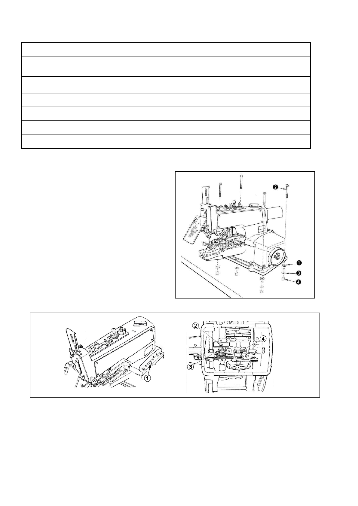
INSTALLATION OF MACHINE HEAD
Put rubber cushion (1) on the tableplace the machi-
ne head on the rubber cushion and fix it to the table
using screws (2) , plain washers (3) and nuts (4) .
LUBRICATION
Apply vaseline oil for sewing machines Spirit 2 to the components shown by the arrows. (Once or twice a week)
Loosen connecting screw (1) , tilt the head backward and apply some grease to driving worm gear (3) and gear (4).
Check, approximately once a week, that oil amount is sufficient to reach the top of the oil felt placed inside the bed mounting base. If the amount of oil is insufficient, add an adequate amount of oil. At this time, also apply oil to crank rod (2).
3
Page 9
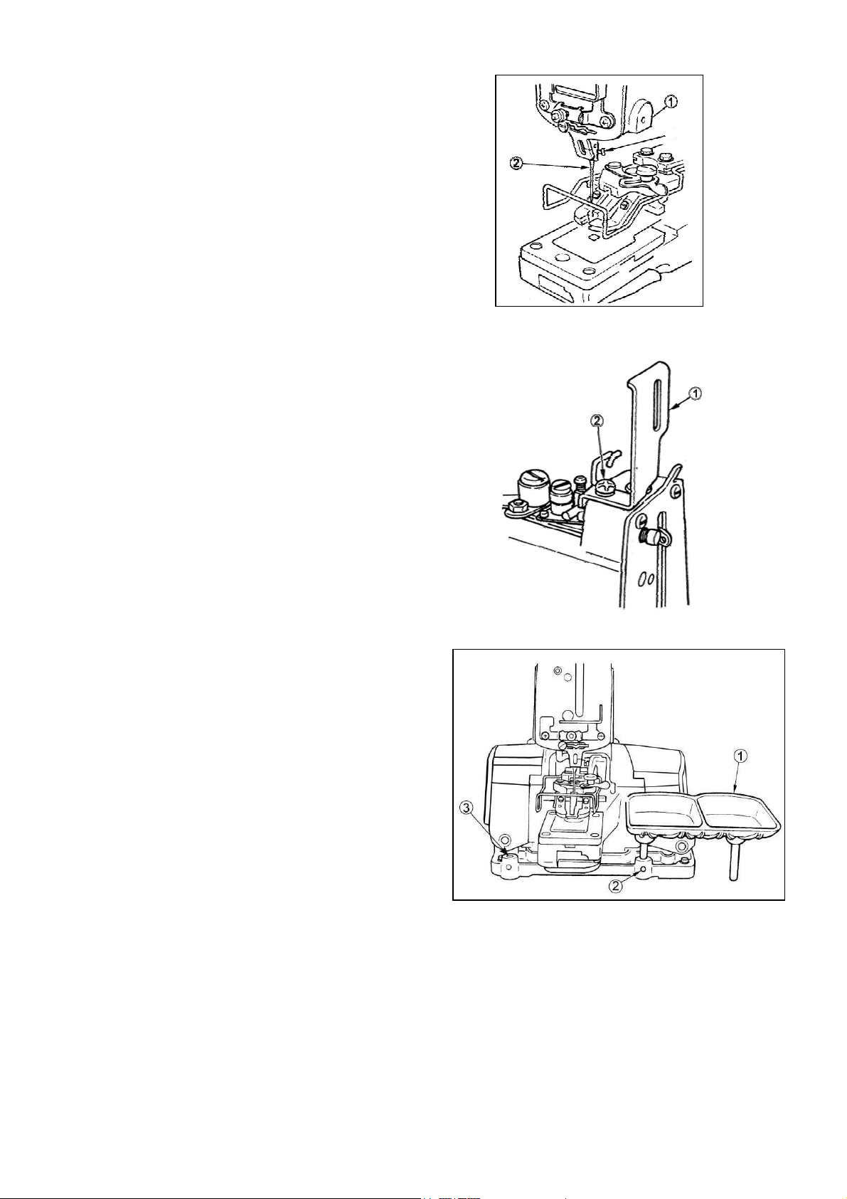
INSERTING THE NEEDLE
1. Loosen screw (1)
2. Insert needle (2) as far as possible.
3. Tighten screw (1).
ATTACHING THE NEEDLE BAR GUARD
1. Loosen screw (2) and remove the thread guide.
2. Place needle guard under the thread guide.
3. Fix the thread guide and needle guard together using screw (2).
TEXI X operation manual
ATTACHING THE BUTTON TRAY ASSEMBLY
Insert the posts of button tray (1) in hole on the right of the machine sub-base and tighten each sets crew (2) .
You may use also the installation hole on the left.
4
Page 10
TEXI Silence Matic Dry operation manual
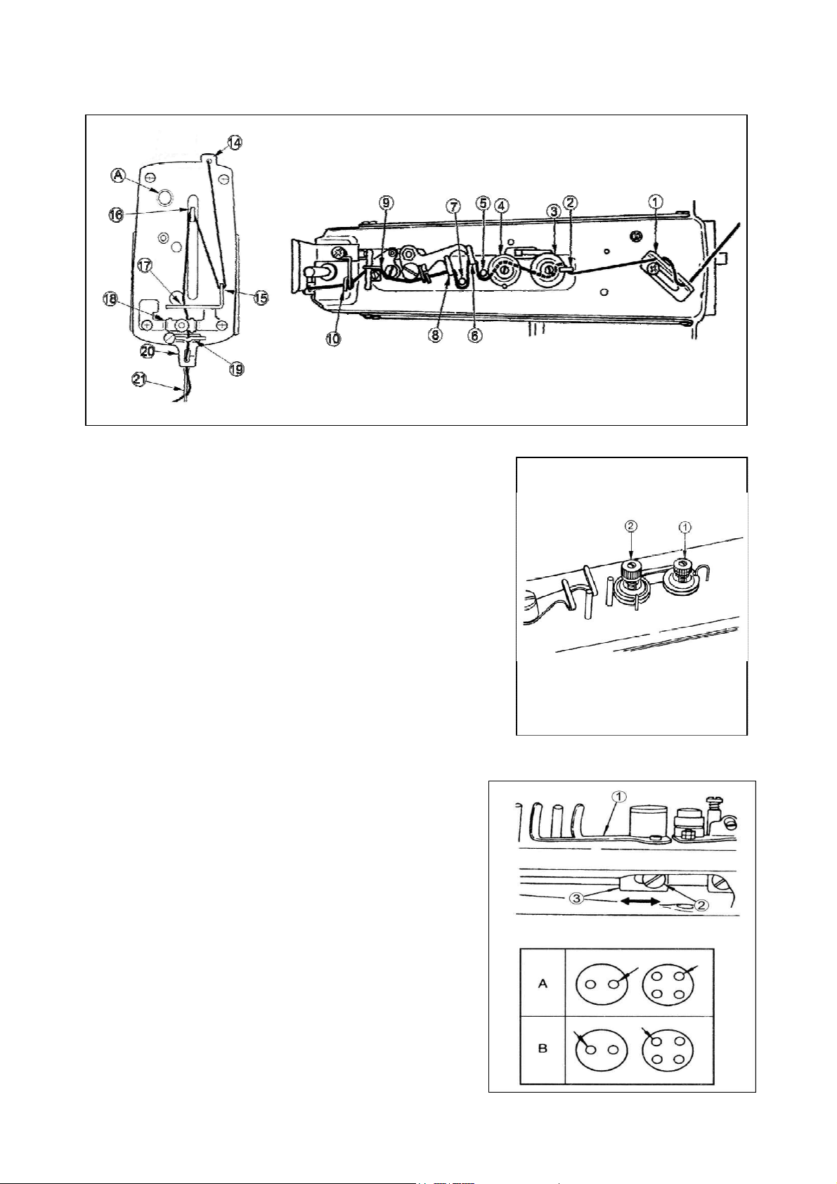
THREADING THE MACHINE
For threading the machine please check below drawing (thread the machine in order from 1-18).
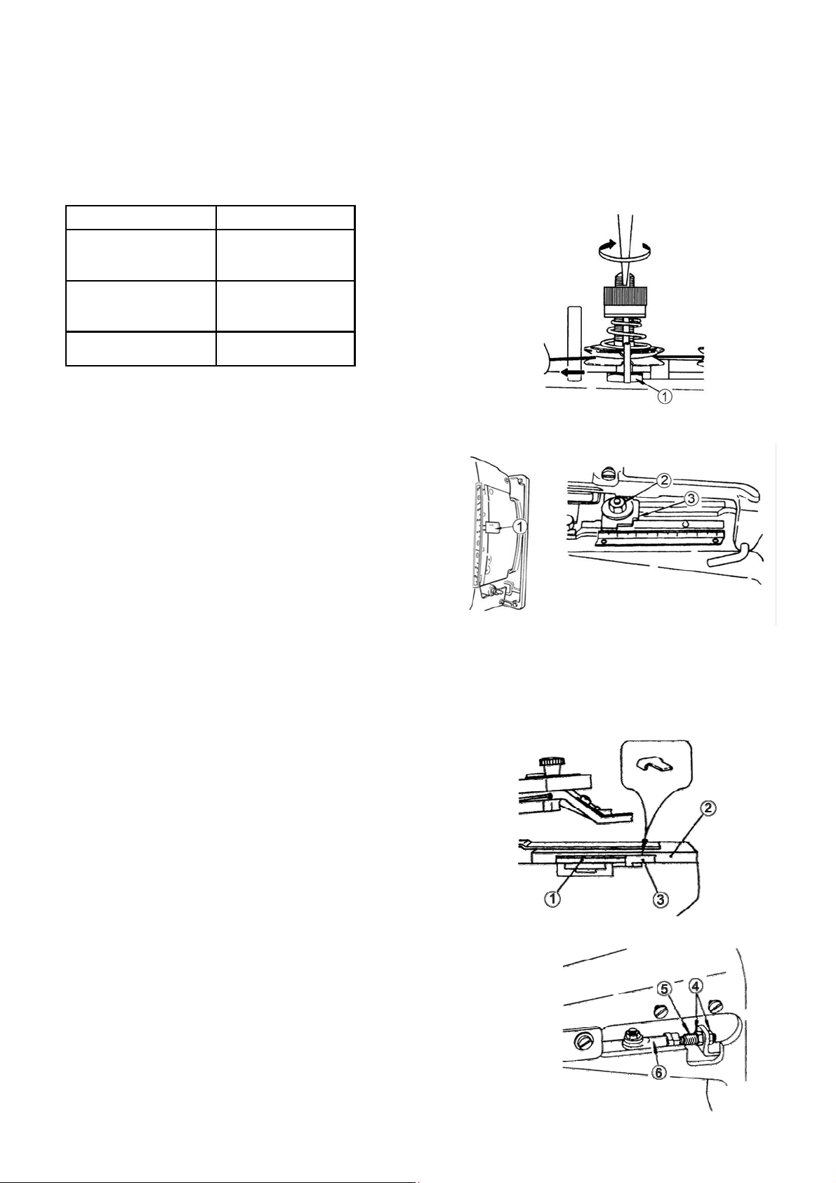
THREAD TENSION ADJUSTMENT
Tension post No.1 is used to adjust the thread tension to sew on the
button and a relatively low tension will be enough.
Tension post No.2 is used to adjust the thread tension applied to the
root of the button sewing stitches.
This tension must be determined according to the type of thread, fabric
and thickness of the button and must be higher than tension set on
post No.1 .
Turn the tension nuts clockwise to increase or counterclockwise to
reduce the thread tension.
ADJUSTMENT OF THE THREAD PULL-OFF LEVER
To adjust the thread pull-off lever (1), insert a screwdriver through an
opening in the machine arm side cover (left), loosen screw (2) and
adjust the position of nipper bar block (rear) (3) to the left or the
right.
If the end of thread is drawn from arrow hole A in the button after
sewing, change the position of nipper bar block (rear) (3) to the left.
Move the lever to the right when the thread end comes out from
arrow hole B.
5
Page 11
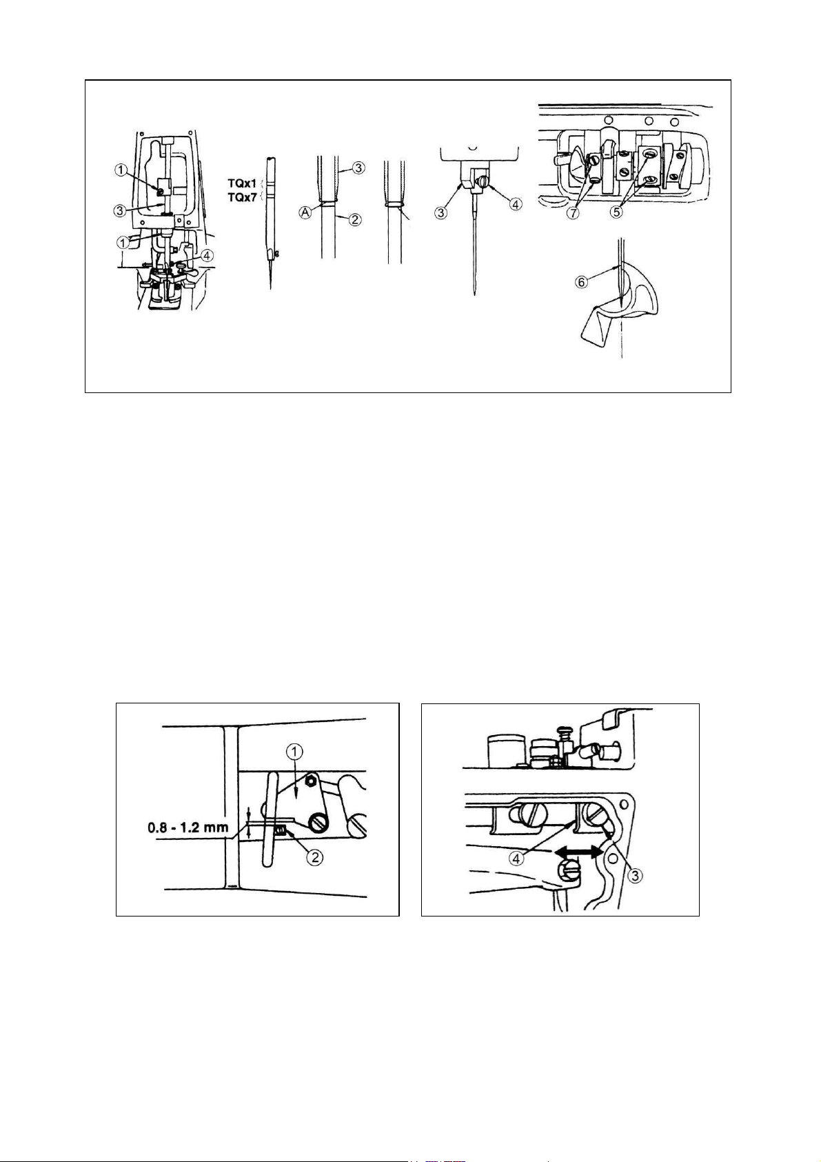
NEEDLE-TO-LOOPER RELATION
Adjust the needle-to-looper relation as follows:
TEXI X operation manual
1. Depress the pedal fully forward, turn the needle driving pulley in the normal sewing direction to bring down the needle bar
to the lowest point and loosen screw (1) .
(Adjusting the needle bar height)
2. Adjust the height of the needle bar using top two lines engraved on the needle bar for the TQxl needle and using the bottom two lines for the TQx7 needle.
Align the upper line A with the bottom end face of needle bar bushing (lower) (3) and tighten screw (1) in the way that needle
clamp screw (4) rests in the slot of the needle bar bushing (lower) (3).
(Looper position)
3. Loosen screws (5) and turn by hand the needle driving pulley until lower line B of two lines aligns with the bottom end face
of needle bar bushing (lower) (3).
4. By keeping the machine in this state, align looper blade (6) with the center of the needle and tighten screws (5).
5. Loosen screws (7) and provide a 0.01 to 0.1 mm clearance between the looper and the needle. Tighten screws (7).
ADJUSTMENT OF THE NIPPER
Provide 0.8 to 1.2 mm clearance between nipper (1) and nipper block (2) to prevent the nipper from nipping the thread
while stitching. Loosen screw (3) and move nipper bar block (4) to the left or the right.
6
Page 12
TEXI Silence Matic Dry operation manual
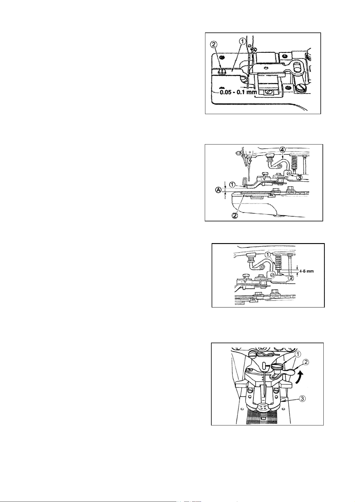
POSITION OF THE NEEDLE GUIDE
Loosen screw (2) and provide a 0.05 to 0.1 mm clearance between the needle guide (1) and the needle, by moving the needle guide (1) to the left or the right when the needle is in the
lowest position.
HEIGHT OF THE BUTTON CLAMP
The standard clearance (1) between the bottom face of button
clamp jaw lever (2) and the top face of feed plate A is 9 mm for
Texi X.
Loosen screw (3) and adjust the height of button clamp lifting
hook (4).
WORK PRESSING FORCE
The standard work pressing force is obtained by providing a 4 to 5 mm
clearance between the bottom face of nut (1) and the bottom end of the
screw of pressure adjusting bar (2).
ADJUSTMENT OF THE BUTTON CLAMP STOP LEVER
Set the machine for stop-motion state, loosen clamp screw (1), place a
button correctly in the sewing position and adjust button clamp stop
lever (2) to permit the button properly to rest on button clamp jaw levers
(3).
Tighten clamp screw after determining the distance
between the left and right jaw levers (1).
7
Page 13
TEXI X operation manual
TIMING OF THREAD TENSION RELEASE
Tum the needle driving pulley as you draw the thread in the direction of the arrow as illustrated and you will find a point at
which the tension disc on the tension post No. 2 release the thread. At this moment, the standard distance from the top end of
the needle bar to the top end of the needle bar bushing (upper) is 44 to 47 mm. Perform the following adjustments especially
when the undermentioned troubles occur frequently.
Loosen nut (1) , insert the blade of a screwdriver to the top slot of the tension post No. 2 and turn it in the direction of the
arrow to lower the needle bar, (to reduce the said distance), and vice versa.
Phenomenon
1. When the stch made
on the wrong side of the
workpiece is too loose;
2. When the thread is
broken at the me of
stop-moon;
3. When the thread is
broken frequently;
Height of needle bar
Make the needle bar
slightly higher.
Make the needle bar
slightly higher.
Make the needle bar
slightly lower.
SETTING FOR 2- OR 4-HOLES BUTTONS
Measure the distance between two holes in a button and set equally
crosswise and lengthwise feed regulators for 4-hole buttons.
Lengthwise feed
Push down lengthwise feed adjusting lever (1) and set it to 0 for 2-
holes buttons or the corresponding amount for 4-holes buttons
Crosswise feed
Loosen nut (2) and set pointer (3) to a corresponding amount indicated by the crosswise feed regulation plate. Tighten firmly nut
(2).
Before operang the machine, ensure that the needle enters the center of each hole in the buon.
AUTOMATIC THREAD TRIMMER
Position of the moving knife
When the machine stops in the state of ―stop-motion" and
its button clamp assembly rests in the highest position, there
must be a standard clearance of 12.5 mm between thread trimming connecting link (front) (1) and the end face of the slit in
throat plate (2). This clearance is determined by gauge (3) which
is stored in the accessory box; tilt the head backwards, remove
the bed oil shield, loosen two nuts (4) and adjust the clearance
by moving connecting screw (5) in the axial direction. When you
tighten two nuts (4), ensure that joint(6) stays in the horizontal
position.
8
Page 14
TEXI Silence Matic Dry operation manual
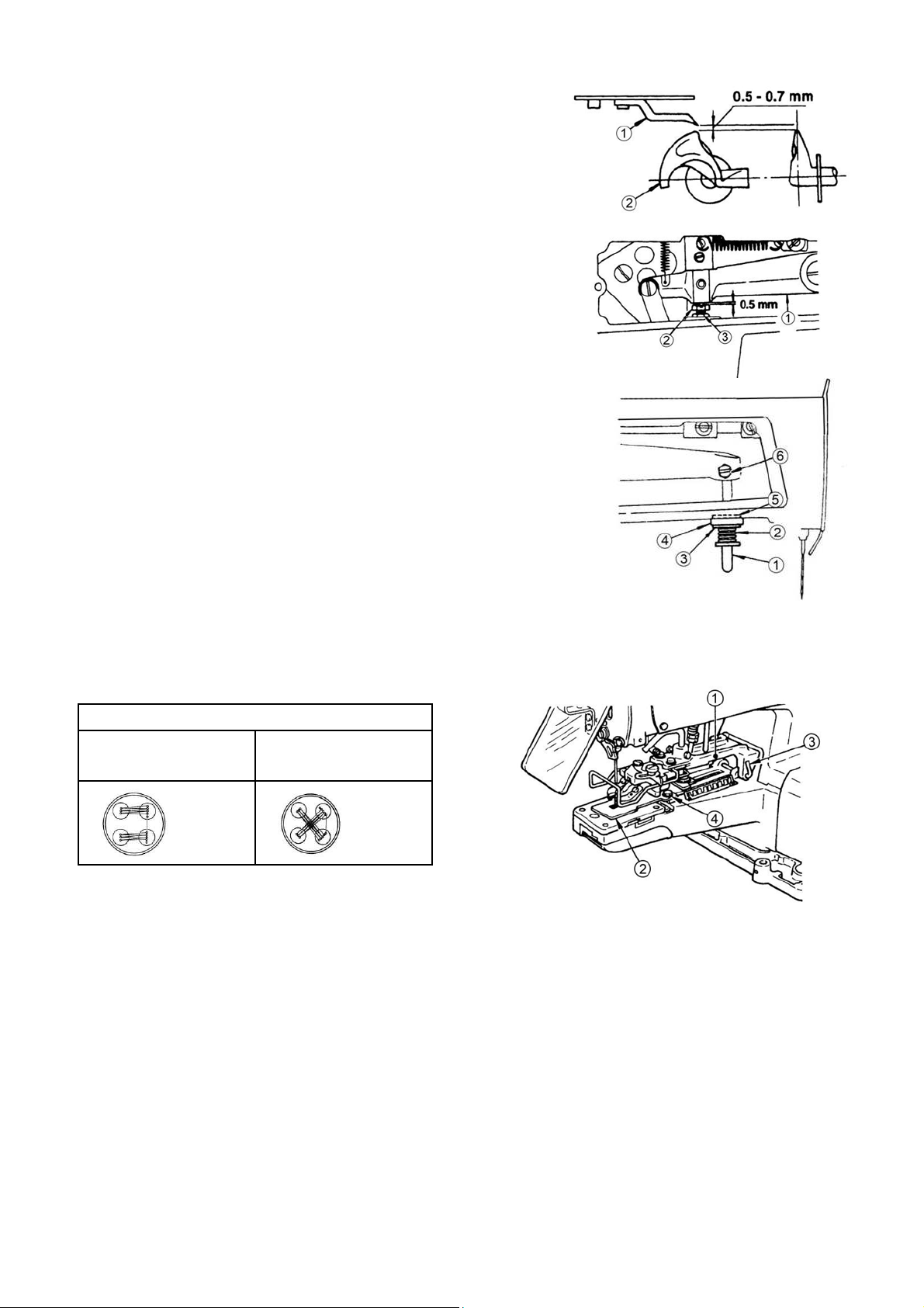
Height of the moving knife thread separation nail
There must be a 0.5 to 0.7 mm clearance between looper blade point (2)
and thread separation nail (1). If nail (1) does not provide the necessary
clearance, bend the nail slightly and adjust the clearance.
Clearance between the button clamp lifting lever and the adjusting screw
Provide a 0.5 mm clearance between button clamp
lifting lever (1) and adjusting screw (2) and then tighten nut 3).
How to set the L-shaped lifting rod
Put moving knife push-back spring (2), stop-motion rubber cushion washer
(3), stop-motion rubber cushion (4) and stop-motion rubber cushion washer
(5), in this order, to L-shaped lifting rod (1). After making sure that the stopmotion mechanism has engaged completely, fix the L-shaped lifting rod by
tightening screw (6) in the way that the end face of the stop-motion rubber
cushion washer come into close contact with the jaw of the machine arm.
STITCHES MODELS
TEXI X
8
16
32stitches
8
16
32 stitches
In order to install the attachment on the machine, you may have to remove the button clamp mechanism (1) or feed plate
(2). Dislocate a snap ring from button clamp installing stud (3)
assembly (1) Loosen sets crews (4)
and you can remove feed plate (2) .
and you will be able to remove button clamp mechanism
9
Page 15

TEXI X operation manual
TROUBLES CAUSES CORRECTIVE MEASURES
1.Thread breakage
2.Buttons are not sewn
tightly
3.The first stitch trails relatively Jong thread from
the right side of the button
The yoke slide does not move in the cor-
rect way.
The thread tension post No. 2 fails to rele-
ase the thread at correct timing,
The thread nipper catches the thread
The needle does not enter the center of
the holes in the button.
The needle is too thick for the diameter of
the hole in the button.
The yoke slide does not move in the cor-
rect way.
The thread tension post No. 2 fails to rele-
ase the thread at correct timing.
The thread tension post No. 2 does not
give sufficient tension.
The needle does not enter the center of
the holes in the button.
The work pressing force is too high or too
low.
The thread pull-off lever does not
work properly.
Adjust the timing of the motion of the yoke
slide at each end.
Make the thread release timing slightly
earlier.
Adjust the position of the nipper bar block.
Adjust the button clamp jaw lever holder.
Replace the needle by a thinner one.
Adjust the timing of the motion of the yoke
slide at each end.
Make the thread release timing slightly
later.
Tighten the tension nut of tension post
No.2.
Adjust the button clamp jaw lever holder.
Adjust the work pressing force
properly.
Ø Adjust the thread pull-off lever by the
nipper bar block (rear).
4.Thread trimming failure in
the state of stop- motion
5.Thread trimming failure
6.The needle thread is cut in
two places on the wrong
side of the fabric
The thread tension post No. 2 fails to rele-
ase the thread at correct timing.
The needle hits the edge of the holes in
the button.
The button clamp assembly does not rise
to the necessary height.
The thread nipper fails to press the thre-
ad.
The work pressing force is too high.
(1)he moving knife does not separate the
thread on the fabric with its separation nail`
(2) The needle does not enter the center
of the holes in the button.
(3)The last stitch skips.
(4)The moving knife thread separation
nail is too high or too low.
The moving knife is set in wrong place.
The moving knife thread separation nail is
too high or too low.
Make the thread release timing slightly
later to give more tension to the sti-
tches
Adjust the button clamp jaw lever holder.
Provide a 12 mm clearance between the
feed plate and the button clamp jaw
levers when rose.
Adjust the nipper bar block.
Adjust the work pressing force by the
pressure adjusting nut.
Adjust the position of the moving knife.
Adjust the button clamp jaw lever holders.
Adjust the looper.
Adjust the height of the moving knife thre-
ad separation nail.
Adjust the position of the moving knife
when the machine is in the stop-
motion state.
Adjust the height of the thread separation
nail.
7.Button traits too long thread after thread trimming
Timing of the moving knife motion is
wrong.
The button clamp assembly rises too
much.
10
Adjust the position of the moving knife.
Reduce the button clamp lift down to 9
mm.
Page 16
TEXI X parts book
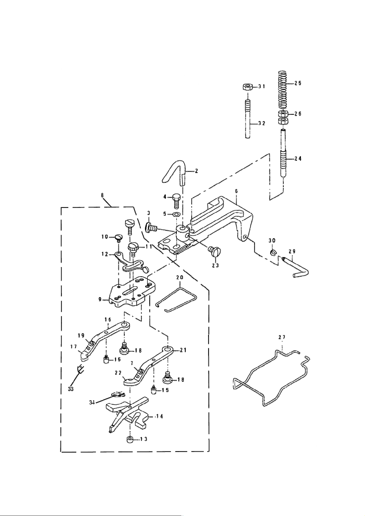
Parts Book
BUTTON CLAMP MECHANISM COMPONENTS
11
Page 17
code DESCRIPTION
1
1 PICK-UP DEVICE ASM.
2 40902001 1 BUTTON CLAMP LIFTING HOOK
3 402S14006 1 SCREW 15/64-28 L=9
4 409S12001 2 SCREW 3/16-32 L=13.5
5 40928001 2 WASHER 5×10.5×1
6 300145 1 BUTTON CLAMP HOULDER
7 409S11002 1 SCREW 9/64-40 L=3.5
8 4091600100 1 BUTTON CLAMP
9 40912002 1 JAW LEVER HOLDER
10 409S20002 1 HINGE SCREW D=5.5 H=1.8
11 409S20003 1 CLAMP SCREW A
12 40912003 1 SNAP FASTENER CLAMP STOP LEVER
13 409S16001 1 NUT
14 40901003 1 BUTTON CLAMP SLIDE
TEXI X parts book
15 409S20004 2 BUTTON CLAMP STOP PIN
16 40912005 1 BUTTON CLAMP LEVER JAW(LEFT)
17 40912006 1 BUTTON HOLDING SPRING LEFT
18 409S20005 2 HINGE SCREW D=6.35 H=3.9
19 409S11002 1 SCREW 9/64-40 L=3.5
20 40927001 1 BUTTON CLAMP SPRING
21 40912008 1 BUTTON CLAMP LEVER JAW RIGHT
22 40912009 1 BUTTON HOLDING SPRING RIGHT
23 402S14006 1 SCREW 15/64-28 L=9
24 409S30016 1 BUTTON CLAMP PRESSUER ADJUSTIN
25 40927002 1 PRESSUER ADJUSTING SPRING
26 409S16003 2 NUT M6
27 40927003 1 FINGER GUARD
29 40902002 1 HINGE PIN
30 H05007 1 SNAP PIN
31 401S16002 1 NUT 15/64-28
32
409S30001 1 PICK-UP DEVICE STOPPER PIN
12
Page 18
TEXI X parts book
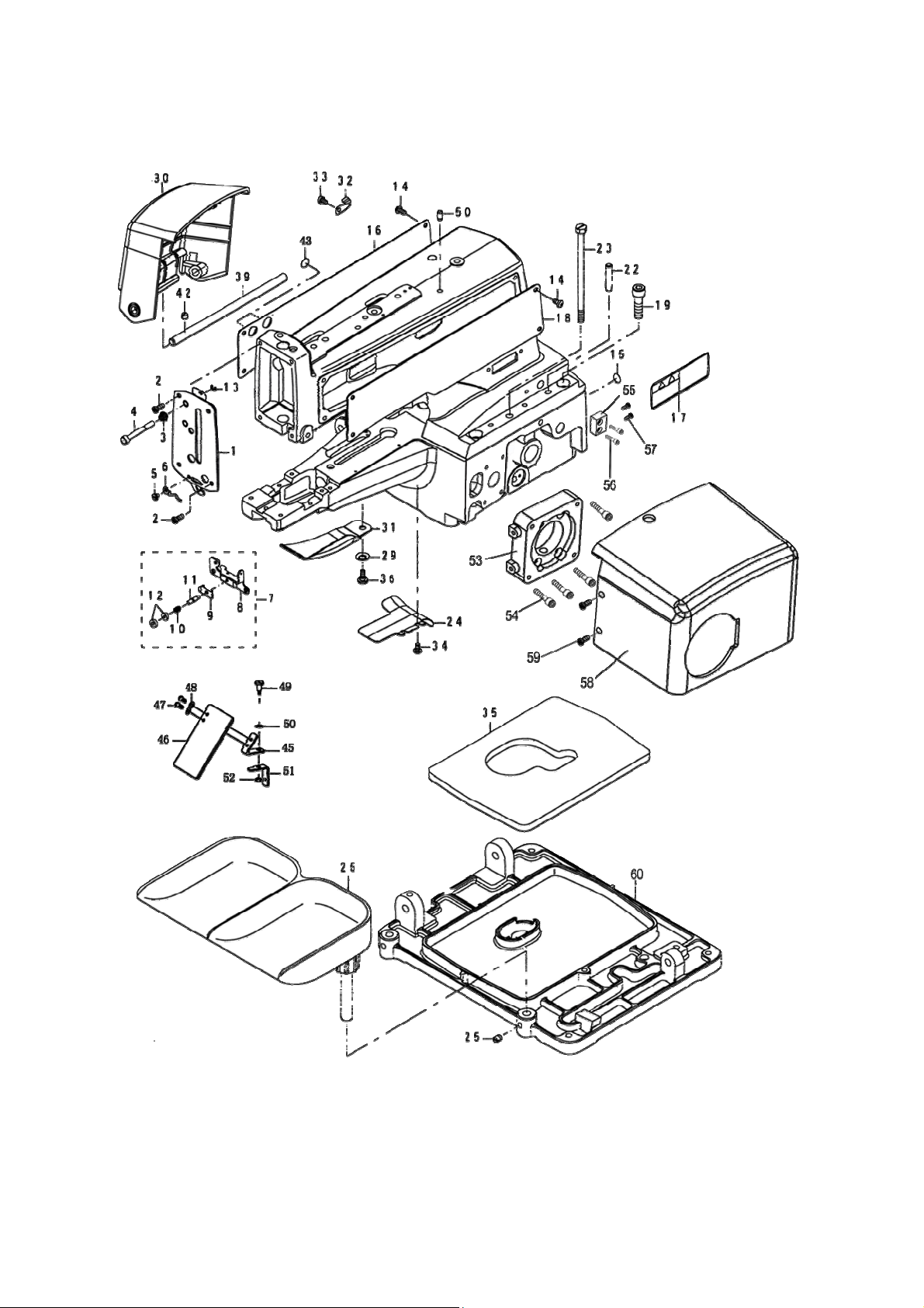
ARM & MISCELLANEOUS COVERS COMPONENTS
13
Page 19
ARM & MISCELLANEOUS COVERS COMPONENTS
DESCRIPTION
1 4091206200 1 FACE PLATE COMPL
2 406S11009 4 SCREW
3 40927004 1 TENSION SPRING
4 40902003 1 NIPPER RELEASING STOP
5 409S11003 1 SCREW
6 40913002 1 THREAD GUIDE NO.4
7 4091301400 1 THREAD TENSION NO.3 ASM.
8 40913015 1 TENSION ADJUSTING BASE NO.3
9 40913016 1 THREAD PRESSER PLATE
10 40927020 1 TENSION SPRING B
11 409S30017 1 THREAD TENSION STUD
12 409S16026 2 THREAD TENSION NUT
13 H05002 1 E-RING 3.2
TEXI X parts book
14 406S11009 8 SCREW
15 40922005 1 RUBBER PLUG
16 40912063 1 SIDE COVER RIGHT
17 40937008 1 SAFETY LABEL
18 40912064 1 SIDE COVER LEFT
19 S05024 4 SCREW M8 L=30
22 P02001 2 GUIDE PIN
23 409S30018 1 SET SCREW
24 40912016 1 BED OIL SHELD
25 402S14006 1 SCREW
26 4091100100 1 BUTTON TRAY ASM
29 40228001 1 SPRING WASHER 6.5×14.0×17
30 40911007 1 SIDE COVER LEFT
31 40912066 1 LOOPER COVER
32 40912067 2 SIDE COVER SPRING
33 409S11006 2 SCREW M4 L=6
34 409S11007 2 SCREW
35 40923013 1 OIL DRIP FELT
36 409S20006 1 SHOULDER SCREW D=6 H=2.7
39 40902019 1 SIDE COVER HINGE SHAFT LEFT
42 402S14006 1 SCREW M6 L=6
43 40122017 1 RUBBER PLUG
45 40112008 2 SAFETY PLATE
46 40911006 2 SAFETY PLATE
47 409S11008 2 SCREW M4 L=6
48 40928002 1 SPRING WASHER 5.0×110
14
Page 20

TEXI X parts book
49 402S20032 1 HINGE SCREW D=6 H=2.5
50 40128001 1 SPRING
51 40912020 1 SAFETY PLATE INSTALLING BASE
52 401S16004 1 NUT SM15/64-28
53 40901028 1 MORTOR BASE
54 413S13012 4 SCREW M5 L=20
55 40901032 1 FIXED SEAT
56 409S11003 2 SCREW SM3/16-28
57 406S11009 2 SCREW SM11/64-40
58 40911009 1 MOTOR COVER
59 409S11003 2 SCREW SM3/16-28
60
40901022 1 OIL RESERVOIR
15
Page 21
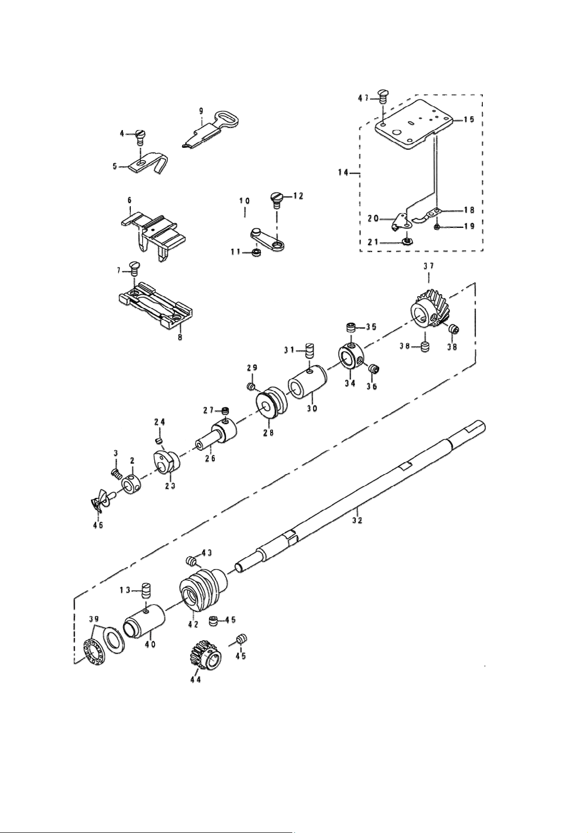
LOOPER SHAFT MECHANISM COMPONENTS
TEXI X parts book
16
Page 22
TEXI X parts book
DESCRIPTION
1
1 THRUST COLLAR .ASM
2 40908002 1 THRUST COLLAR D=7.94 W=7
3 409S11012 1 SCREW 9/64-40 L=6.1
4 409S11010 1 SCREW
5 40912021 1 NEEDLE GUARD
6 40909001 1 POSITONGNING FINGER YOKE SLIDE
7 409S17001 2 SCREW SM11/64-40 L=9
8 40909002 1 YOKE SLIDE INSERT
9 40912022 1 YOKE SLIDE
10 4090500100 1 ASSY LOOP POSITIONING FINGER L
11 40903003 1 LOOP POSITIONNING FINGER CAM RO
12 409S20008 1 HINGE SCREW D=6.35 H=2.4
13 401S14001 1 SCREW
14
1 THROAT PLATE SET
15 40901005 1 THROAT PLATE ASM.
18 40919003 1 COUNTER KNIFE
19 409S11011 2 SCREW1/8-44 L=3.0
20 4091900100 1 MOVING KNIFE ASM.
21 409S20009 1 HINGE SCREW D=6 H=0.85
22
1 ASSY LOOP POSITIONING FINGER C
23 40910001 1 LOOP POSITIONING FINGER CAM
24 409S14002 2 SCREW 11/64-40 L=3.5
25
1 ASSY CAM AND LOOPER SLEEVE
26 40902006 1 CAM AND LOOPER SLEEVE
27 409S15004 2 SCREW 15/64-28 L=4.0
28 40910001 1 LOOP POSITIONGNING FINGER CAM RE
29 409S14002 2 SCREW 11/64-40 L=2.8
30 40903004 1 LOOPER SHAFT BUSHING FRONT
31 401S14001 1 SCREW
32 40902026 1 LOOPER SHAFT
33
1 THRUST COLLAR ASM, D=11.11,W=1
34 40908001 1 THRUST COLLAR ASM, D=11.11,W=10
35 409S14003 1 SCREW 1/4-40 L=5
36 409S14004 1 SCREW 1/4-40 L=5
37 40925002 1 LOOPER SHAFT DRIVER GEAR ASM.
38 409S14001 2 SCREW 1/4-40 L=6
39 40928004 1 THRUST BALL BEARING
40 40903005 1 LOOPER SHAFT BUSHING REAR
41
1 WORM WHEEL ASM.
42 40925009 1 WORM
17
Page 23

43 409S14003 2 SCREW 1/4-40 L=7
44 40925001 1 CAM SHAFT ASM.
45 409S14003 2 SCREW 1/4-40 L=6
46 40917001 1 LOOPER
TEXI X parts book
47
409S11009 3 SCREW M11/64-40 L=9
18
Page 24
TEXI X parts book
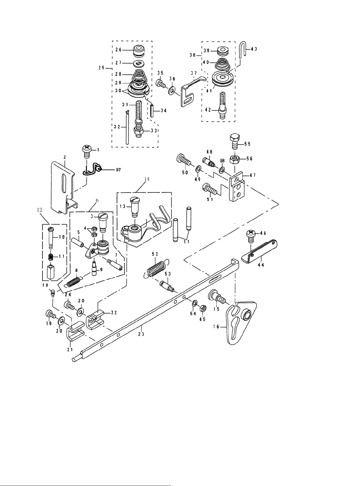
NIPPER & THREAD TENSION PARTS COMPONENTS
19
Page 25
DESCRIPTION
1 409S11013 1 SCREW SM15/64-28 L=12
2 40912024 1 NEEDLE BAR GUARD
3 409S20010 1 SHOULDER SCREW
4 409S16005 2 NUT
5 409S16006 1 NUT
6 4091202500 1 NIPPER COMPL
7 409S20011 1 LOOPER SHAFT BUSHING REAR
8 40927007 1 NIPPER BAR BLOCK SPRING
9 409S30004 1 NIPPER BAR BLOCK SPRING SCREW
10 409S20012 1 HINGE SCREW D=4 H=20
11 40927008 1 HIPPER SLIDE BLOCK SPRING
12 40909003 1 NIPPER BLOCK
13 409S20013 1 SHOULDER SCREW D=7.94 H=15
14 4091300400 1 THREAD PULL OFF LEVER ASM.
TEXI X parts book
15 409S20014 1 SHOULDER SCREW D=7.94 H=8
16 4091202700 1 NIPPER BAR ACTUATING LEVER ASM.
17 40926006 2 THREAD GUIDE PIN
18 40926007 1 NIPPER BAR BLOCK SPRING PIN
19 409S11014 1 SCREW
20 40928004 2 WASHER
21 40912029 1 NIPPER BAR BLOCK
22 40912030 1 TENSION LEVER ROCKING PIECE
23 40912031 1 NIPPER BAR
24 409S11014 1 SCREW
25 4091300600 1 TENSION POST ASM NO.2
26 409S16007 1 TENSION NUT
27 40912032 1 ROTATION STOPPER
28 40927009 1 THREAD TENSION SPRING
29 40912033 1 THREAD TENSION DISK PRESSER
30 40913007 2 THREAD TENSION NO.1
31 409S30006 1 TENSION POST NO.2
32 409S16008 1 TENSION RELEASE PIN
33 40926008 1 NUT M6
34 P03009 1 SPRING PIN 3×16
35 409S11014 1 SCREW
36 40928004 1 WASHER
37 40912034 1 THREAD TENSION RELEASING LEVER
38 4091300800 1 ASSY HTREAD RENSION NO.1
39 409S16009 1 THREAD TENSION NUT
40 40927010 1 FIRST THREAD TENSION SPRING
20
Page 26
TEXI X parts book
41 40913007 2 THREAD RENSION DISK NO.1
42 409S30007 1 THREAD RENSION POST NO.2
43 40913009 1 THREAD GUIDE
44 40913010 1 THREAD GUIDE NO.1
45 409S16010 1 NUT
46 409S11013 1 SCREW
47 40912100 1 NIPPER BAR BEARING BLOCK
48 409S30008 1 ADJUSTING SCREW
49 40928005 1 WASHER 5.5×10×0.8
50 409S11015 1 SCREW
51 409S11016 1 SCREW
52 40927011 1 THREAD TENSION SPRING
53 409S30009 1 NIPPER BAR SPRING SCREW
54 40928006 1 WASHER
55 409S12002 1 SCREW
56 409S16011 1 NUT
57 40913012 1 THREAD GUIDE
58
40928005 1 WASHER 5×10.5×1
21
Page 27
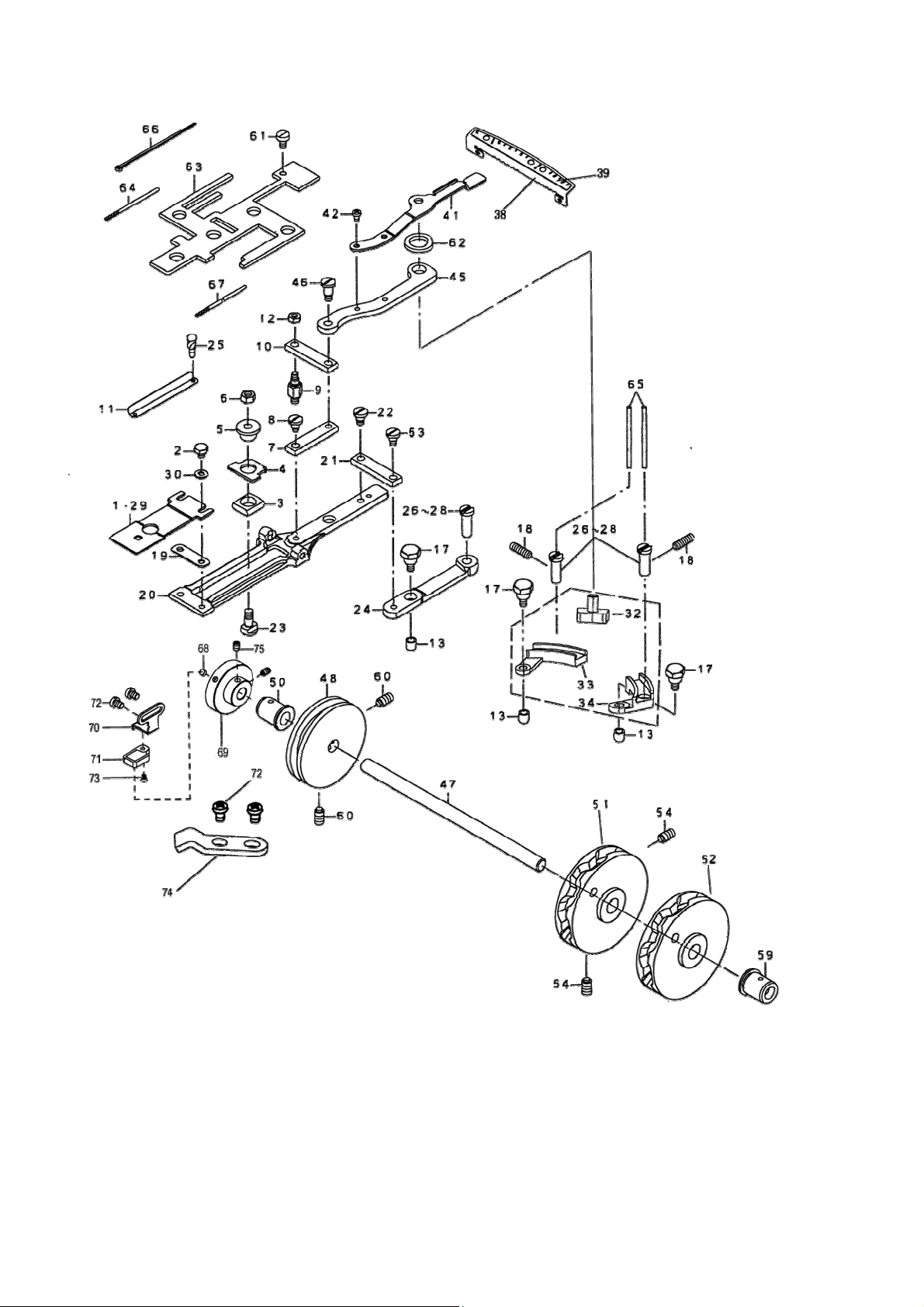
FEED PLATE COMPONENTS
TEXI X parts book
22
Page 28
TEXI X parts book
DESCRIPTION
1 40915001 1 FEED PLATE SMALL BUTTON
2 409S12003 2 SCREW 3/16-28 L=6
3 40909004 1 LNDICATOR PIN BEARING BLOCK
4 40912036 1 CROSSWISE FEED INDICATOR
5 40903010 1 CROSSWISE FEED INDICATOR PIN
6 409S16012 1 NUT M=6
7 400110 1 SLIDE PLATE CONNNECTING LINK
8 409S20015 1 HING SCREW D=6.35 H=4.8
9 409S30010 1 STUD
10 400111 1 INTERMEDI CONNECTING LINK
11 40937001 1 CROSSWISE FEED GRADVATED PLATE
12 409S16013 1 NUT M5
13 40903012 2 CAM ROLL
17 409S30011 2 CAM ROLL SCREW STUD
18 401S14001 1 SCREW SM15/64-28 L=12
19 40912040 1 SPACER PLATE
20 40901006 1 FEED PLATE
21 40909006 1 INTERMEDI CONNECTING LINK
22 409S20015 1 HING SCREW D=6.35 H=4.8
23 409S30012 1 HING SCREW FOR CROSSWISE FEED
24 40904003 1 CROSSWISE FEED LEVER
25 R01002 5 RIVET
26 40902021 1 FEED STUD A
27 40902021 1 FEED STUD B
28 40902021 1 FEED STUD C
29 40915001 1 FEEED PLATE SMALLBUTTON
30 40912068 2 WASHER 5×10.5×1
32 40909019 1 LENGTHWISE FEED LEVER SLIDE
33 40909020 1 FEED LEVER L
34 40909021 1 FEED LEVER R
35 40912069 2 FEED KNOB GUIDE PLATE
36 409S12006 1 SCREW M5×0.8 L=8
38 40912070 1 PLATE BASE
39 40911009 1 GRADUATE PLATE
41 40912071 1 HANDLE AND INDICATOR SPRING
42 409S11018 2 SCREW M4 L=6
43 409S11003 2 SCREE
45 40904004 1 INDICATOR SPRING CONNECTING LI
46 409S20016 2 SHOULDER SCREW D=6.35 H=9.7
47 40902022 1 CAM SHAFT
48 40910019 1 LENGRHWAISE FEED CAM(X)
23
Page 29
50 40903015 1 CAM SHAFT BUSHING LEFT
51 40910006 1 LATERAL FEED CAM
52 40910004 1 LONGITUDINAL FEED CAM
53 409S20015 1 SHOULDER SCREW D=6.35 H=4.8
54 401S14001 2 SCREW 9/32-28 L=13.5
59 40903013 1 CAM SHAFT BUSHING RIGHT
60 401S14001 4 SCREW 9/32-28 L=13.5
61 409S11005 1 SCREW M5 L=8
62 40923014 1 OIL RETAINING FELT
63 40923015 1 FEED SHOULDER SCREW FELT
64 40923008 0.06 OIL WICK
65 40923008 0.06 OIL FELT
66 40111005 4 CABLE BAND
67 40923008 0.3 OIL WICK
68 40930007 1 MAGNET
TEXI X parts book
69 40930003 1 SINGLE WHEEL
70
71
1 HALL SWITCH HOLDER
1 HALL SWITCH
72 409S11003 2 SCREE
73
2 SCREE
74 41312003 2 WIRE BUCKLE
75
402S14006 2 SCREW,15/64-28
24
Page 30
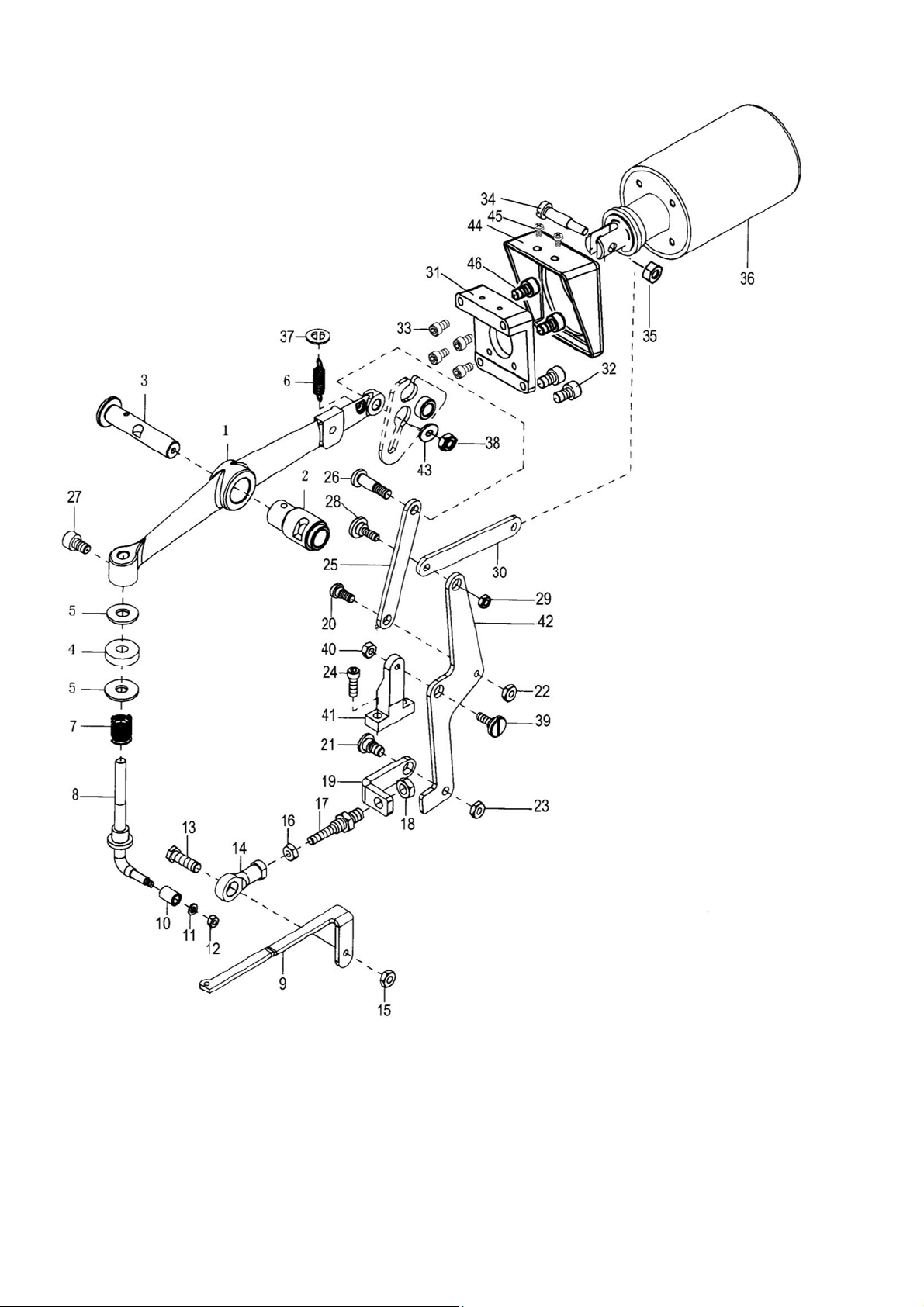
TEXI X parts book
BUTTON CLAMP LIFTER COMPONENTS
25
Page 31
DESCRIPTION
1 40901033 1 LIFTING LEVER
2 40903016 1 BUSHING
3 40902009 1 NDDELE BAR LEVER
4 40928014 1 WASHER 8.5×18.0×1.2
5 40922001 1 CUSHION
6 40927012 1 SPRING
7 40927013 1 SPRING
8 40912074 1 BUTTON CLAMP LIFTING ROD A
9 40912042 1 CONNECTING LINK FRONT
10 40903032 1 L TYPE LIFTING BAR ROLLER
11 40928021 1 WASHER
12 409S13003 1 NUT 9/64-40
13 L01002 1 JOINT STUD
14 4090500400 1 FEED ADJUSTING JOINT
TEXI X parts book
15 N01004 2 NUT M5
16 409S16015 2 NUT
17 409S30013 1 CONNECTING SCREW
18 409S16015 2 NUT
19 40912043 1 CONNECTING LINK REAR
20 409S20020 1 HINGE SCREW D=6.35 H=3.2
21 409S20021 1 HINGE SCREW D=7.94 H=4
22 409S16016 1 NUT 3/16-32
23 409S16017 1 NUT 15/64-28
24 409S11021 2 SCREW 11/64-40 L=14
25 40905006 1 THREAD TRIMMING LINK
26 409S20023 1 HINGE SCREW D=6.35 H
27 S05023 1 SCREW M6 L=10
28 409S20038 1 HINGE SCREW D=6.35 H
29 401s16002 1 NUT 3/16-32
30 40912091 1 Magnet connect pole
31 40912092 1 Magnet holder
32 413S13019 4 SCREW M5 L=12
33 413S13016 4 SCREW M4 L=8
34 409S20039 1 PIN
35 413S16003 2 NUT M4
36 40930005 1 ELECTROMAGNET
37 40912032 1 WASHER
38 401S16002 1 NUT
39 409S20040 1 SHOULDER SCREW D=7.94 H=3.1
26
Page 32

TEXI X parts book
40 409S16018 1 NUT M5
41 40901034 1 THREAD TRIMMING LEVER BASE
42 4091210000 1 CRANK ROD
43 40128034 1 WASHER
44 40911010 1 ECTROMAGNET COVER
45 403S11027 2 SCREW M4 L=7.5
46
S05035 2 SCREW M5 L=25
27
Page 33
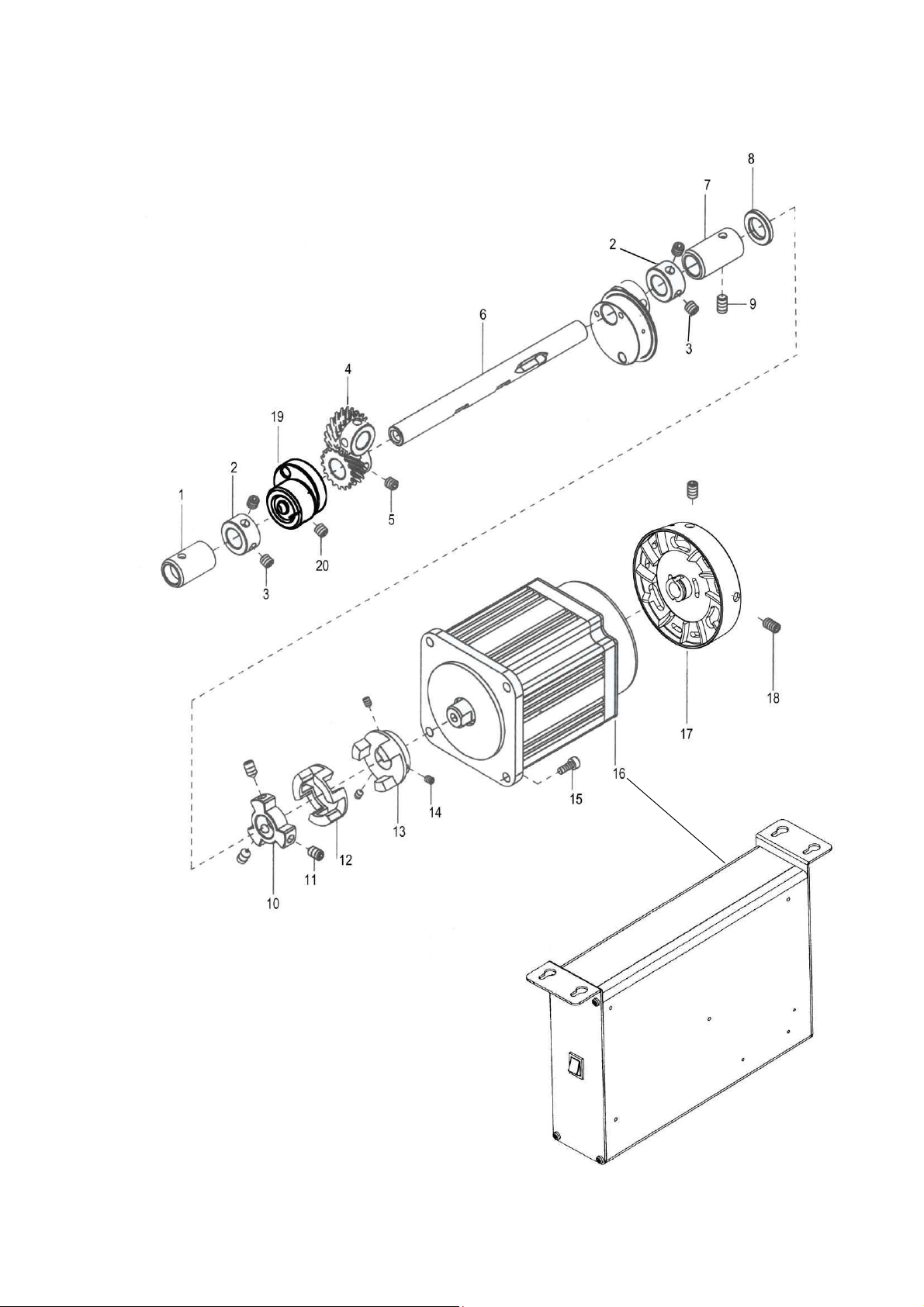
NEEDLE DRIVING PULLEY SHAFT COMPONENTS
TEXI X parts book
28
Page 34
TEXI X parts book
DESCRIPTION
1 40903034 1 PULLEY SHAFT BUSHING LEFT
2 40603020 2 THRUST COLLAR
3 403S14004 2 SCREW M6
4 40925004 1 DRIVING GEAR(A) ASM.
5 409S14001 2 SCREW 1/4-40 L=6
6 40902024 1 NEEDLE DRIVING PULLEY SHAFT
7 40903024 1 PULLEY SHAFT BUSHING RIGHT
8
1 SPACE
9 401S14001 1 SCREW 15/64-28
10 40901030 1 MAIN SHAFT CONNECTOR
11 403S14004 3 SCREW M6
12 40222040 1 MAIN SHAFT CONNCECTOR WASHER
13 40201069 1 MOTOR CONNECTOR
14 403S14004 3 SCREW M6
15 S05035 4 SCREW
16 40933001 1 MOTOR
17 302443 1 PULLEY
18 403S14004 3 SCREW M6
19 40910007 1 ECCENTRIC CAM
20
409S14003 2 SCREW
29
Page 35
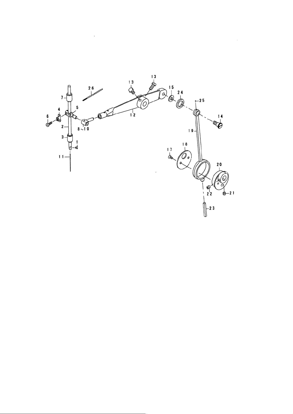
NEEDLE BAR DRIVING MECHANISM COMPONENTS
TEXI X parts book
30
Page 36
TEXI X parts book
DESCRIPTION
1 101S11006 1 SCREW,1/8-44,L=4.5
2 40902027 1 NEEDLE,ROD
3 40903026 1 NEEDLE,BAR,BUSHING,LOWER
4 40913013 1 NEEDLE,BAR,BALACE
5 40909016 1 NEEDLE,BAR,CLAMP
6 409S11024 1 SCREW,M4,L=12
7 40903035 1 NEEDLE,BAR,BUSHING,UPPER
8 40909016 1 NEEDLE,BAR,SLIDE,BLOCK,A
9 1 NEEDLE,BAR,SLIDE,BLOCK,B
10 1 NEEDLE,BAR,SLIDE,BLOCK,C
11 41017001 1 NEEDLE,TQ×1,#16
12 40905007 1 NEEDLE,BAR,DRIVING,LEVER
13 L02008 2 SCREW,M6,L=14
14 409S20025 1 SHOULDER,SCREW,D=9.53,H=8
15 40928013 1 WASHER
16 1 CRANK,ROD,ASM.
17 409S11009 2 SCREW,11/64-40,L=8.5
18 40912046 1 THRUST,HOLDER
19 40905009 1 CRANK,ROD
20 40910009 1 ECCENTRIC,CAM
21 40910009 1 SCREW,1/4-40,L=6
22 409S14001 1 SCREW,1/4-40,L=8.5
23 40923008 1 OIL,WICK
24 40923014 1 OIL,RETAINNING,FELT
25 40923008 0.01 OIL,WICK
26
40923008 0.1 OIL,WICK
31
Page 37

TEXI O operation manual
CE DECLARATION OF CONFORMITY
Distributor:
Strima Sp. z o.o.
Swadzim, st. Poznańska 54
62-080 Tarnowo Podgórne, Polska
We declare, that the following product:
Industrial button sewing machine
Texi X (JM-2377D)
which this declaration relates, complies with the following directives:
Machine directive 2006/42/WE
Low voltage directive 2006/95/WE
Harmonized norm used: EN 60204-1
32
Page 38

Page 39

Page 40

Dealer:
 Loading...