

Page 1
Installation Manual
Premier 640
Issue 1
Page 2

Contents Premier 640 Installation Manual
2 INS344
Contents
1. New Features....................................................... 4
Area Profiles ............................................................. 4
User Profiles ............................................................. 4
Access Profiles......................................................... 4
User Programming ................................................... 4
Default Settings ........................................................ 4
Mandatory Log.......................................................... 4
Alternative Wiring Configurations............................ 4
Additional Radio Devices......................................... 4
2. System Overview ................................................5
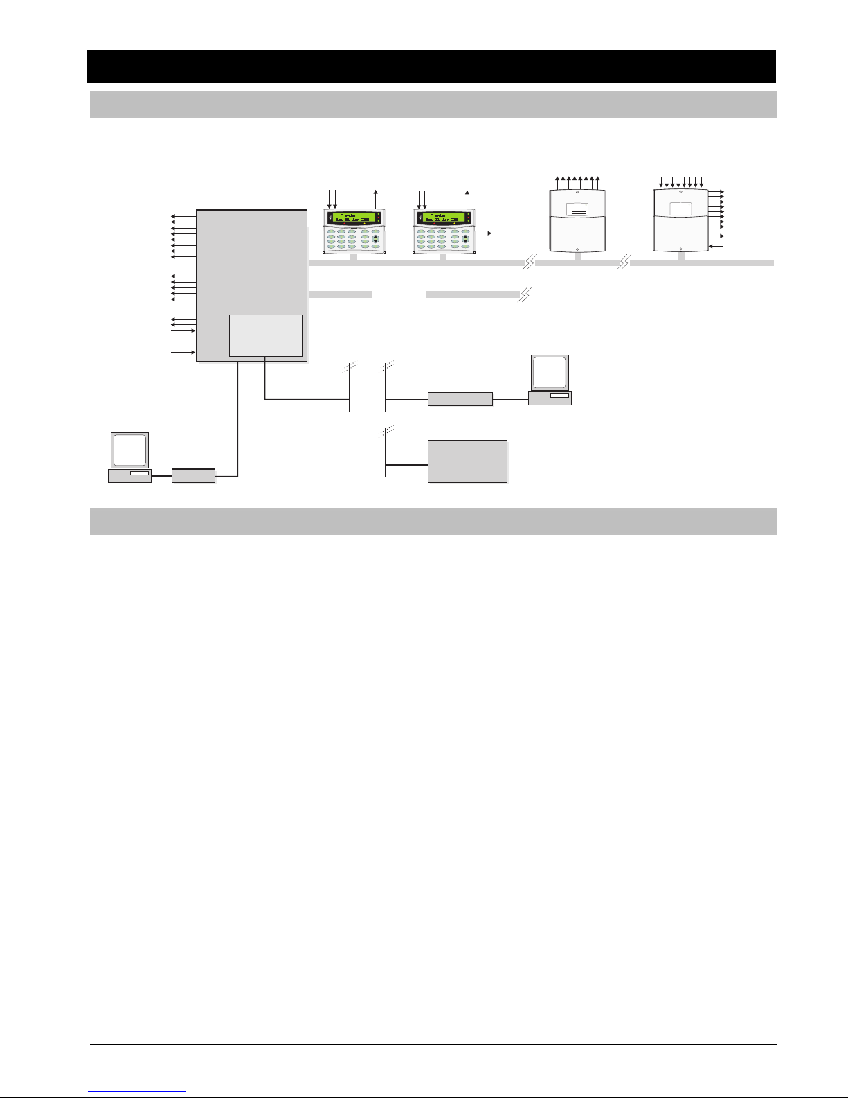
System Architecture................................................. 5
Control Panel............................................................ 5
Remote Keypads ...................................................... 6
Zone Expanders........................................................ 6
Output Expanders..................................................... 6
Communicators ........................................................ 6
Other Devices ........................................................... 7
3. Installation........................................................... 8
Installation Sequence............................................... 8
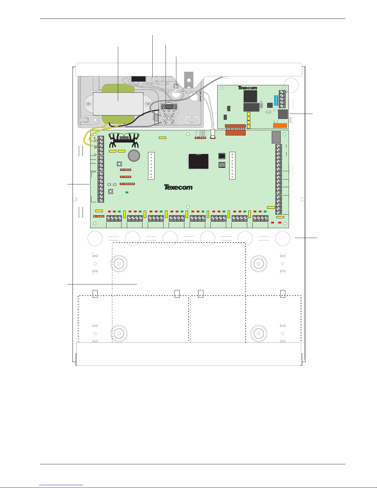
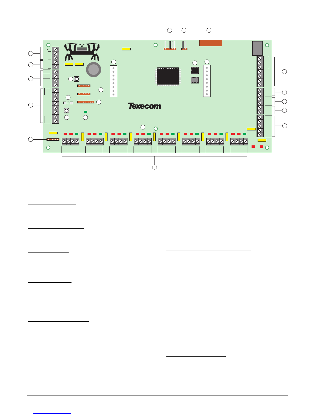
Control Panel............................................................ 8
Power Supply Ratings............................................ 12
Connecting AC Mains............................................. 12
Connecting Batteries.............................................. 12
Connecting Devices to the Network ...................... 13
Remote Keypads .................................................... 15
8XP Zone Expander ................................................ 16
4 XP Zone Expander ............................................... 17
iProx Module........................................................... 17
60IXD Zone Expander ............................................. 18
OP16 Output Expander........................................... 19
Zone and Output Numbering ................................. 20
Zone Connections .................................................. 21
Auxiliary Tamper Connections............................... 22
Speaker Connections............................................. 22
External Sounder Connections.............................. 22
Panel Outputs 1 - 5................................................. 23
Digicom Outputs 1 - 8............................................. 23
2-Wire Smoke Detector .......................................... 24
Expander Auxiliary Input ........................................ 24
Plug-on Communicators ........................................ 25
RP9 Radio-Pad........................................................ 26
GSM Module ........................................................... 26
AV Module............................................................... 26
ComIP Module........................................................ 26
PC-Com................................................................... 27
UNI-Com ................................................................. 27
PRINT-Com ............................................................. 27
RPD-Com ................................................................ 27
GSM-Com................................................................ 27
Connecting a Computer ......................................... 27
Connecting a Printer .............................................. 27
4. Commissioning and Troubleshooting ............. 28
Commissioning....................................................... 28
Trouble-Shooting.................................................... 28
Reset and Service Messages................................. 30
5 Programming the Control Panel ....................... 31
Introduction ............................................................ 31
Factory Defaults ..................................................... 31
Programming Menu Guide..................................... 32
Programming Text.................................................. 33
Copying and Pasting.............................................. 33
Log Off Engineer .................................................... 33
Resetting the Engineers Code (User 00)............... 33
Other Things to Know ............................................ 33
5.1 Zone Setup ...................................................... 34
Zone Types ............................................................. 35
Zone Attributes 1.................................................... 36
Zone Attributes 2.................................................... 36
Attributes for Moment or Latch Keys..................... 37
Attributes for Custom Zones.................................. 37
Zone Areas.............................................................. 37
Zone Text ................................................................ 37
Zone Chime ............................................................ 37
Remote Test Enable ............................................... 37
Zone Wiring ............................................................ 38
DD 243 .................................................................... 38
5.2. Area Programming......................................... 39
Timers ..................................................................... 39
Arming Modes ........................................................ 40
Area Arm Suites...................................................... 40
Area Suite Text ....................................................... 41
Suite Arm Modes.................................................... 41
Area Options........................................................... 42
Time Arm Area........................................................ 45
Area Text................................................................. 46
Area Profiles ........................................................... 46
5.3 Global Options ................................................47
System Timers........................................................ 47
System Config. ....................................................... 48
System Options ...................................................... 51
Monitor Hardware................................................... 52
Control Timers........................................................ 52
System Text ............................................................ 53
Part Arm Text.......................................................... 53
Holiday Dates ......................................................... 54
Speaker Tones........................................................ 54
PC Output Text ....................................................... 55
Custom O/P Text .................................................... 55
Page 3

Contents Premier 640 Installation Manual
INS344 3
5.4 Keypad Setup .................................................. 56
Keypad Areas..........................................................57
Keypad Zone Mapping............................................57
Keypad Options ......................................................57
Keypad Speaker Volume ........................................57
Keypad Sounder Options .......................................57
5.5 Expander Setup ............................................... 58
Expander Areas.......................................................59
Expander Location Text ..........................................59
Expander Auxiliary Input.........................................59
Expander Speaker Volume .....................................59
Expander Sounder Options ....................................59
5.6 System Outputs............................................... 60
Available Outputs....................................................61
Programming Outputs ............................................61
Output Group - Not Used........................................ 61
Output Group - System...........................................61
Output Group - Area................................................63
Output Group - Zone...............................................65
Output Group - User Code Entered........................65
Output Group - Control Timer ................................65
Output Group - PC Control.....................................65
Output Group - Door Control..................................65
Output Attributes.....................................................66
X-10 Outputs............................................................66
Custom Outputs......................................................66
5.7 UDL/Digi Options.............................................67
Reset Digi ................................................................67
Start Test Call..........................................................67
MSN/Pre-Dial No. .................................................... 67
Program Digi ...........................................................68
Digi Options ............................................................71
Area Accounts......................................................... 71
UDL Options............................................................72
Radio/SMS Options.................................................74
Com Port Setup.......................................................76
Zone Alarm Reporting Codes.................................78
5.8 Setup Users .....................................................84
Add/Edit Users ........................................................84
Programming New Users........................................85
User Name Text.......................................................85
Deleting Users.........................................................85
User Profiles............................................................86
User Profile Text......................................................87
User Options ...........................................................87
User Options 1 ........................................................87
User Options 2 ........................................................87
User Options 3. .......................................................87
User Options 4 ........................................................88
User Time Lock .......................................................88
Predefined User Profiles.........................................88
User Functions and Options For Predefined User
Profiles ....................................................................89
Access Profiles .......................................................90
5.9 Engineer Utilities.............................................91
View Event Log........................................................91
Do Bell Test............................................................. 94
Do Walk Test ........................................................... 94
View Zone Status ....................................................95
Do System Tests ..................................................... 95
Confirm Devices .....................................................96
View RKP Status .....................................................96
View Exp. Status .....................................................96
Set System Time ..................................................... 97
Set System Date......................................................97
Change Eng. Code.................................................. 97
Adjust Volumes ....................................................... 97
Default NVM Data.................................................... 98
Location Text........................................................... 98
Print Log Data .........................................................98
Soak Test Areas...................................................... 98
View iD Data ............................................................ 99
Configure Radio...................................................... 99
5.10 Programming Part Arms.............................100
Alter Part Arms...................................................... 100
6. Specifications..................................................101
Control Panel ........................................................101
Remote Keypads................................................... 102
Zone Expanders.................................................... 102
Output Expanders................................................. 103
Standards.............................................................. 103
Warranty ................................................................ 103
EN50131 Markings................................................ 103
Declaration of Conformity .................................... 104
Page 4

System Overview Premier 640 Installation Manual
4 INS344
1. New Features
With Version 8 Software, the capacity of the Premier 640
has been significantly enhanced.
The new panel can accommodate up to 500 users and 64
areas.
In order to manage the additional capacity, some changes
to the programming have been made which are briefly
described in this section.
Area Profiles
Area profiles are used to group areas together into suites
this is a useful way to identify any number of areas which
belong to a single entity such as a company or floor in a
multi-occupancy building.
80 Area profiles are provided each of which can be
programmed with any combination of 64 areas.
Each area profile can be named to relate it to the installation.
Each zone is then allocated to an area profile in the same
way as they were previously assigned to an area.
Area profiles can also be allocated to users, keypads and
expanders in the same way as was previously done with
areas.
User Profiles
The panel provides 32 user profiles for managing the
functions and features available to different types of users.
There are a number of predefined user profiles by default
which may well satisfy all the requirements of an installation.
Two profiles, Engineer and Master are required to have
particular features and are not editable, the remaining 30
can be customized by the Engineer or Various users
depending on the specific settings.
A user profile defines the functions and features available to
a particular type of user.
Once a user profile has been defined it can be allocated to
any number of individual users.
This approach simplifies the programming of users in a large
system as the profile only has to be set up once, then it is a
simple matter for the profile to be applied to a particular
group of users.
Using user profiles has the advantage that any changes can
be applied to the profile once and they will automatically be
applied to any user allocated to the profile.
Access Profiles
One of the functions provided by Texecom Alarm Panels is
door control, allowing electronic door locks to be activated
by designated outputs on keypads or proximity units.
The 640 provides 99 access profiles, each defining how
access is granted to any combination of up to 64 door
controls.
Access profiles are programmed and allocated in a similar
way to user profiles, but are allocated to individual users
independently of the user profile.
User Programming
To program a user it is necessary first to program the user,
area and access profiles.
Set up the user and program a user code, then allocate the
appropriate profiles.
If at some later stage it is necessary to make changes, either
change the appropriate profile, (which will effect all users
allocated to the profile) allocate different profile which
matches the new requirement or program a new profile and
allocate it to the user.
Each user can have any combination of user, area and
access profiles.
Default Settings
All users are assigned to Area Profile 80 (All System Areas).
Users are also set to ‘No Door Access’ by default.
Area Profiles 1-64 are each assigned to an individual area,
(Profile 01 to area A1, Profile 02 to area A2 and so on to
Profile 64 assigned to area H8.
Area Profile 00 is defaulted as no areas and Profile 80 is all
areas.
All zones are assigned to Area Profile 1 (Area A1).
Access Profiles 1 -64 are each assigned to an individual
door (Profile 01 to Network 1 Door 1, Profile 02 to Network 1
Door 2 and so on to Profile 64, assigned to Network 8 Door
8).
Mandatory Log
The component requirements for control equipment
TS50131-3 requires that mandatory log events are not
overwritten by non-mandatory events.
To satisfy this requirement an additional 500 mandatory
event log has been created which records only the
mandatory events.
Operation of the standard system log has not been changed
and mandatory events will be duplicated in the standard log.
The standard log has been extended to 5000 events.
Alternative Wiring Configurations
4 new EOL zone wiring options have been provided to allow
compatibility with other manufacturers products and to allow
the use of alternative anti-masking detection devices.
Normally open & normally closed contacts are catered for,
this is primarily for key switches
A warning device monitoring circuit type has been provided
to support remote testing of sounders.
Additional Radio Devices
The number of RadioPlus intelegent radio devices that can
be learnt to the system has been increased from 32 to 100.
This is mainly to accommodate the additional users and
allow more radio FOBs.
Page 5
Premier 640 Installation Manual System Overview
INS344 5
2. System Overview
System Architecture
8 Programmable
100mA Outputs
(Digi Outputs)
Bell Tamper Input
Auxiliary Tamper Input
5 Programmable
A & 1 Relay)
Outputs
(4 x 500m
Control
Panel
Premier LCD/LCDP
Premier LCDL/LCDLP
4 Wire Data Network 1
16 Programmable
100mA Outputs
64 Keypads
(Up to 8 per network)
Premier OP16
32 Output Modules
(Up to 4 per network)
Alarm Receiving
Centre
Modem
PC and Modem for
Remote Upload/Download
PC-Com
PC and for
Local Upload/Download
PC-Com
Plug on Digimodem
Plug on
(Com300, Com2400
or ComISDN)
Radio-Pad,
GSM Module
2 Zone
Inputs
1Programmable
100mA Output
2 Zone
Inputs
1Programmable
100mA Output
Speaker
Output
4 Wire Data Network 2-8
Speaker Output
8 Zone Inputs
Auxiliary Input
Premier 8XP
8 Programmable
100mA Outputs
64 Expanders
(Up to 8 per network)
Wire as Network 1
2 to 640 Zones
Via Expanders & Keypads
Bell/Strobe Outputs
Power
NetworkNo
Address
Zones
Power
NetworkNo
Address
Zones
Power
Info.
Ready
Service
Omit
Area
Yes
Part
Chime
Omit
Reset
Menu
2
abc
No
1
3
def
6
mno
9
wxyz
5
jkl
8
tuv
0
4
ghi
7
pqrs
640
7
Power
Info.
Ready
Service
Omit
Area
Yes
Part
Chime
Omit
Reset
Menu
2
abc
No
1
3
def
6
mno
9
wxyz
5
jkl
8
tuv
0
4
ghi
7
pqrs
640
7
Control Panel
• Expandable to 640 zones via keypads and zone expanders
• 8 x 4-wire data network (standard 7/0.2 alarm cable)
• Up to 64 keypads and 64 zone expanders (8 per network)
• Up to 32 output modules (4 per network)
• 64 independent areas each with 3 part arms
• 500 programmable User codes
• 5000 Event Log (time & date stamped)
• 500 Event Mandatory Log (time & date stamped).
• 32 Event Alarm Log (time & date stamped).
• 5 programmable panel outputs (4 x 1A & 3A relay)
• 2.0 Amp power supply
• 8 programmable digicom outputs (100mA each)
• 32 character zone text
• Facility for Plug-on Digimodem (Com300/2400/ComISDN)
• Facility for Plug-on Paknet RP9 Radio-Pad
• Facility for Plug-on GSM Module
• Facility for Plug-on IP Module (ComIP/Chiron/WebWayOne)
• Facility for a plug-on RedCARE/RM8 Relay Module
• Facility for a plug on Engineers Keypad.
• PC-Com/printer port
Page 6

System Overview Premier 640 Installation Manual
6 INS344
Remote Keypads
Premier LCD
• 32 character text display
• 2 fully programmable DP or EOL zones
• 1 fully programmable output (100mA -ve applied)
• Fully adjustable back-lighting, normally bright, dim or off,
changing to bright during entry or following a key press
• Built in piezo sounder
• Programmable ‘Info.’ LED
Premier LCDL
ALL the features of the Premier LCD plus:
• Larger 32 character text display
• Speaker output
Premier LCDP
• Premier LCD with a built in Proximity Tag Reader
Premier LCDLP
• Premier LCDL with a built in Proximity Tag Reader
Zone Expanders
Premier 4XP
• 4 fully programmable DP or EOL zones
• 2 fully programmable outputs (100mA -ve applied each)
• Remotely wired
Premier 8XP
• 8 fully programmable DP or EOL zones
• 8 fully programmable outputs (100mA -ve applied each)
• Speaker output
• Programmable auxiliary input
• Remotely wired
Premier PSU200XP
• Monitored Power Supply with integral Premier 8XP
Premier 60iXD
• 2 loops x 30 fully programmable iD zones
• iD biscuit technology
• Plug-on
“iD” is a registered trade mark of Chloride Safety System Limited
RadioPlus Intelligent Receiver
• Plug – 0n receiver for Texecom RadioPlus devices.
• Accepts 32 Devices
RadioPlus Network Receiver
• Network version of the Intelligent Radio Reciever..
Output Expanders
Premier OP16
• 16 fully programmable outputs (100mA each)
• 1 fault output (100mA -ve applied)
• Can be connected to mimic panels to give zone indication
• Can be connected to relays and sounders
Premier RM8 Relay Module
• Plug-on relay card (RedCARE footprint)
• 8 separate inputs for stand alone operation
• 8 x 3Amp relay outputs (n/o, n/c, com)
• Output ‘ON’ LED indication
Communicators
Com300
• Multi-protocol communicator supporting Fast Format,
Contact ID, SIA Level II and EasyCom Pager protocols
• 300-baud modem for remote uploading and
downloading using the Wintex UDL software and a PC
• For use with an analogue telephone line (REN = 1)
Com2400
• Multi-protocol communicator supporting Fast Format,
Contact ID, SIA Level II and EasyCom Pager and SMS
Messaging protocols
• 2400-baud modem for remote uploading and
downloading using the Wintex UDL software and a PC
• Sends SMS text messages to mobile phones
• For use with an analogue telephone line (REN = 1)
ComISDN
• Multi-protocol communicator supporting Fast Format,
Contact ID, SIA Level II and EasyCom Pager protocols
• 300-baud (analogue) or 19200-baud (digital) Modem for
remote uploading and downloading using the Wintex
UDL software and a PC
• For use with an ISDN telephone line
ComIP
• Multi-protocol communicator supporting Fast Format,
Contact ID and SIA Level II protocols via TCP/IP
• High speed modem for remote uploading and
downloading using the Wintex UDL software and a PC
• For use with ADSL/DSL/Broadband/WAN/LAN etc.
RP9 Radio-Pad
• Paknet radio communicator supporting Fast Format and
Contact ID protocols
• 4800-baud modem for remote uploading and
downloading using the Wintex UDL software and a PC
GSM Module
• Provides a GSM telephone path for Premier Digital
Communicators
• Sends SMS text messages to mobile phones
• Arm, Disarm, Reset the alarm, turn outputs on and off,
omit zones and send messages to the control panel
using SMS text messages
• 9600-baud modem for remote uploading and
downloading using the Wintex UDL software and a PC
Page 7

Premier 640 Installation Manual System Overview
INS344 7
Other Devices
PremieriProx
• Provides an alternative to Prox keypads for setting &
unsetting with a proximity FOB.
• Remote Prox readers available for external or internal
use.
• Interfaces with 26 bit Wiegand devices.
• Can be used as standalone door entry control
PC-Com
• For connecting a PC to the control panel via an RS232
Serial port allowing local uploading and downloading using
Wintex UDL software
USB-Com
• For connecting a PC to the control panel via a USB 1.0 or
2.0 port allowing local uploading and downloading using
Wintex UDL software
UNI-Com
• For connecting a serial device i.e. PC modem or mobile
phone to the control panel
PRINT-Com
• For connecting a serial printer to the control panel
RPD-Com
• For connecting a RP9 Radio-Pad to the control panel
GSM-Com
• For connecting a GSM Module to the control panel
Premier X10-Com
• For controlling X10 enabled devices on the ring main.
Premier Battery Splitter
• Allows two backup batteries to be connected to a single
set of battery terminals, and will provide appropriate
monitoring and charging for each.
External Sounders
• Texecom supply a range of external sounders
Page 8

Installation Premier 640 Installation Manual
8 INS344
3. Installation
Installation Sequence
Before attempting to install the alarm system, read this
section. Once you have an overall understanding of the
installation sequence, carefully work through each step.
1: Design the Layout
Make a rough sketch of the premises to get an idea of where
the alarm detection devices, keypads, zone expanders etc.
are to be located.
2: Mounting the Panel
The control panel should be mounted in a dry area close to
an unswitched AC power source and the incoming telephone
line (if using a communicator).
!
You must complete all wiring before connecting the
battery or applying AC mains to the control panel.
3: Install the Keypads and Zone Expanders
Mount and connect the keypads, zone expanders and output
modules to the control panel (see page 13 for wiring details).
4: Install the Alarm Detection Devices
Install the detection devices, PIR’s, Contacts, PA Buttons etc.
and connect them to the control panel (see page 21 for wiring
details).
5: Install the External Sounder
Install the external sounder and connect to the control panel
(see page 22 for wiring details).
6: Other Wiring
Complete all other wiring including speakers, telephone line
and output connections etc. (see pages 22 - 23 for details).
7: Applying Power to the Control Panel
Once steps 1 to 6 are completed, power can be applied to
the control panel.
When applying power for the first time, the factory default
settings must be loaded (see page 28 for details). Power
should always be connected in the following order:
• Connect the red battery lead to the positive terminal of
the battery and then connect the black battery lead to the
negative terminal
!
The panel will only become ‘live’ when the AC
Mains is connected or the ‘Battery Kick-start’
button is pressed.
• Connect the AC mains
8: Programming the Control Panel
Please refer to section 5 for instruction on programming the
control panel.
9: Testing the System
Test the system thoroughly to ensure that all features and
functions operate as required (see page 91 for details).
Control Panel
Mounting
Mount the control panel on a flat, plumb wall using at least
three screws of appropriate size.
!
It is essential to ensure that none of the fixing slots or
cable entries are accessible after fixing.
Mains cabling must be secured (e.g. with a cable tie) to
one of the anchor points provided.
Wiring the Control Panel
WARNING: ELECTRICITY CAN KILL
BEFORE connecting the control panel ALWAYS
disconnect the supply at the consumer unit.
If in ANY doubt consult a qualified electrician.
"
IMPORTANT SAFETY INFORMATION. HAZARDOUS
VOLTAGES INSIDE, NO USER SERVICEABLE PARTS,
NO USER ACCESS.
!
ONLY connect the mains supply to the mains terminal
block, NEVER connect the mains supply directly to the
PCB.
ALWAYS refer to National Wiring Regulations when
conducting installation.
An appropriate and readily accessible disconnection
device (e.g. an unswitched fused spur) MUST be
provided as part of the installation.
The disconnection device must NOT be fitted in a
flexible cord.
Where identification of the neutral in the mains supply
is NOT possible a two-pole disconnection device
MUST be used.
The building mains supply MUST incorporate
appropriate short-circuit backup protection (e.g. a fuse
or circuit breaker) of High Breaking Capacity (HBC, at
least 1500A).
Use mains cable of adequate carrying capacity for the
rated current (i.e. at least 0.75mm
2
).
Page 9
Premier 640 Installation Manual Installation
INS344 9
Control Panel Layout
2
79
Com 2
Com 1
Expansion
Load
Defaults
Engineer
Remote
Kick
Start
OP1-
Tamp
OP5
N/O COM N/C
+12v
Bell
Strb
0v
OP2-
OP3+
OP4+
Box
Tamp
BATT
A.C.
DC+
L/M
R/R
DC
-
2
3
5
6
7
8
4
1
DIGICOM OUTPUTS
+
-
V
1
00mA = 1 Amp
Heartbeat
Aux
Tamp
Aux 12v
-
+
Spk+
Spk
-
NETWORK 2NETWORK
1
+
- T R+- T R
NETWORK 3
+
- T R
NETWORK 4
+
- T R
NETWORK 5
+
- T R
NETWORK 6
+
- T R
NETWORK 7
+
- T R
NETWORK 8
+
- T R
Tx RxFault Tx RxFault Tx RxFau lt Tx RxFault Tx RxFault Tx RxFault Tx RxFau lt Tx RxFau lt
Com 3
F4
F13
F5
F6
F7
F8 F9 F10 F11 F12
F2
F3
F1
Bell/Spk
Fault
Aux12V
Fault
T
R
T1
R1
Back Tamper Screw
Mains Terminal Block & Fuse
Tamper Switch
Mains Transformer
Control Panel
Circuit Board
Space for
Batteries
Plug-on
Digimodem
Cable Enties
!
If back tamper is required, the back tamper screw must be fitted as indicated.
Page 10
Installation Premier 640 Installation Manual
10 INS344
Control Panel PCB Layout
1: AC Input
Connected to the 16.5V transformer.
DO NOT CONNECT THE MAINS SUPPLY TO THE AC
INPUT TERMINALS ON THE PCB.
2: Battery Connections
A 12V rechargeable battery must be connected to these
terminals in order to provide continuous system operation in
the event of an AC Mains failure (see page 12 for details).
3: Digicom Power & Inputs
These terminals provide unfused power; remote reset and line
fault inputs and are normally used for connecting a stand-alone
communicator to the control panel (see page 23 for details).
4: Digicom Outputs
Outputs 1 to 8 are low current (100mA ‘-ve’ applied) and
would normally be used when connecting a stand-alone
communicator to the control panel (see page 23 for details).
Each output is fully programmable (see page 61 for details).
5: Engineers Keypad
A portable Engineers keypad can be plugged on here to
allow easier access for programming and testing.
!
When using a keypad as an Engineers keypad, the
address must be set to ‘10’ (see page 15 for details).
The keypad zones and lid tamper are not monitored.
6: Network Data Connections
Networks provide connection for the keypads and zone
expanders. The ‘+’ and ‘–’ terminals provide power whilst
the ‘T’ transmits data and ‘R’ receives data (see page 13 for
details).
7: Auxiliary 12V Power
These terminals are for connecting devices that require 12V
power (protected by a 1A fuse).
8: External Sounder Connections
These terminals are used for connecting to an external
sounder unit (see page 22 for details).
9: Auxiliary Tamper Connections
These terminals can be used for monitoring the tamper loop of
an auxiliary device (see page 21 for details).
10: Loudspeaker Connections
These terminals can be used for connecting up to one 16Ω
or two 8Ω loudspeakers (see page 22 for details).
11: Panel Outputs
Outputs 1 & 2 are 500mA ‘-ve’ applied, outputs 3 & 4 are
500mA ‘+ve’ applied and output 5 is a clean contact relay
(see page 23 for wiring details). These outputs are all fully
programmable (see page 60 for details).
12: Plug-on Communicator Connections
This socket provides connection for Premier plug-on
communicator (see page 25 for details).
13: Box Tamper Connection
The box tamper micro switch is connected here. The micro
switch provides tamper protection for the main control panel in
case of unauthorised access. To disable the box tamper,
remove the micro switch lead and fit a jumper link across the
two pins.
14: Plug-on RedCARE/Dualcom Connections
These pins provide connections for a plug-on RedCARE,
Dualcom, Digicom or RM8 Relay module. Each output is fully
programmable (see page 61 for details).
!
When a device is plugged on to these pins, not all
outputs may be available, please refer to the relevant
documentation for details.
15: Battery Kick-start Button
When powering up the panel without AC Mains present, this
button must be pressed in order to connect the battery.
!
If AC Mains is present this button does not need to be
pressed.
Com 2
Com 1
Expansion
Load
Defaults
22
15
12
Engineer
Remote
5
17
14
16
13
Kick
Start
OP1-
Tamp
OP5
N/O COM N/C
+12v
Bell
Strb
0v
10
8
11
OP2-
OP3+
OP4+
6
7
19
18
Box
Tam p
BATT
A.C.
DC+
L/M
R/R
DC
-
2
3
5
6
7
8
4
1
DIGICOM OUTPUTS
1
3
4
2
+
-
V
1
00mA = 1 Amp
21
Heartbeat
20
Aux
Tamp
9
Aux 12v
-
+
Spk+
Spk
-
NETWORK 2NETWORK 1
+
-
T R
+
-
T R
NETWORK 3
+
-
T R
NETWORK 4
+
-
T R
NETWORK 5
+
-
T R
NETWORK 6
+
-
T R
NETWORK 7
+
-
T R
NETWORK 8
+
-
T R
14
Tx RxFault Tx RxFault Tx RxFault Tx RxFault Tx RxFault Tx RxFault Tx RxFault Tx RxFault
Com 3
F4
F13
F5
F6
F7
F8 F9 F10 F11 F12
F2
F3
F1
16
Bell/Spk
Fault
Aux12V
Fault
Page 11

Premier 640 Installation Manual Installation
INS344 11
16: Communication Ports
Com Port 1 is a serial communications port and can be used
for connecting a PC running Wintex or any supported serial
device to the control panel (see page 76 for details).
Com Port 2 is a serial communications port and can be used
for connecting a PC running Wintex or any supported serial
device to the control panel (see page 76 for details).
Com Port 3 is a serial communications port and can be used
for connecting a PC running Wintex or any supported serial
device to the control panel (see page 76 for details).
17: Network Data Indicators
The red LED indicates that data is flowing out of the control
panel and normally flashes very quickly. The green LED
indicates that data is flowing into the control panel and
normally flashes slowly, the green LED flashes faster as more
devices are connected (see page 13 for details).
18: Load Defaults Button
Press and hold this button whilst applying power to the
control panel to load the factory default settings. Press and
hold this button for 7 seconds with power already on the
panel to restore just the Engineer code to the factory setting
of
!"#$
.
!
Loading the factory defaults can take up to 60 seconds
to complete.
Loading defaults will only be possible if the NVM has
not been locked (see page 49 for details).
For a complete list of factory defaults, see the Factory
Defaults and Quick Reference Guide supplied separately
with the control panel.
.
19: Expansion
The Expansion Port can be used for connecting a 60XPiD
Zone Expander (see page 18 for details) or an AV Module
(see page 26 for details).
20: Heartbeat LED/Power Light
Flashes steadily to indicate that the control panel is
functioning correctly. If the light is ON or OFF all the time,
then there could be a problem (see page 28 for details).
21: Current Reading Pads
To calculate the current draw of the control panel, measure
the voltage across the two pads and multiply by 10 i.e.
Reading = 34mV (x10) = 340mV = 340mA.
22: NVM
All system programming data and the system & event logs
are stored in a removable non-volatile memory devices.
Page 12
Programming the Control Panel Premier 640 Installation Manual
12 INS344
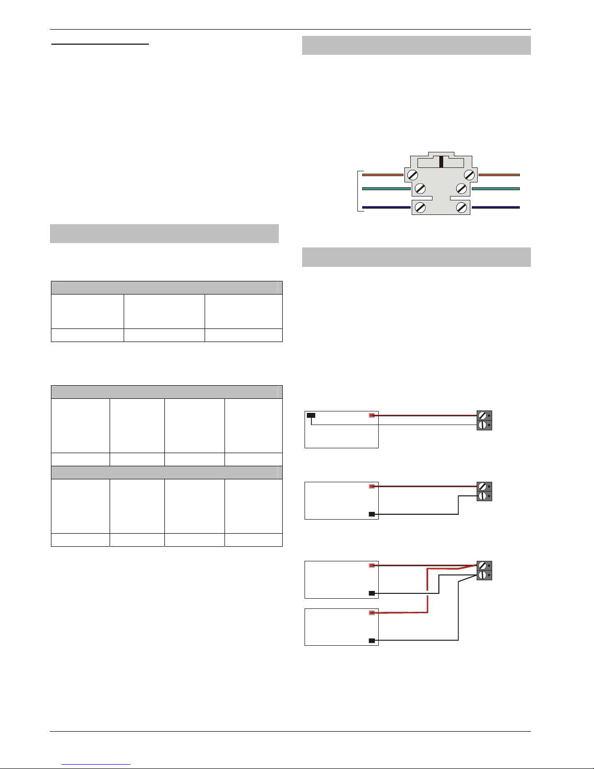
F1 - F5: Protection Fuses
The following electronic fuses are provided:
• F3 (1600 mA) Battery
• F4 (250mA) Speaker
• F5 (900mA) Network 1
• F6 (900mA) Bell/Strobe
• F7 (900mA) Network 2
• F8 (900mA) Network 3
• F9 (900mA) Network 4
• F10 (900mA) Network 5
• F11 (900mA) Network 6
• F12 (900mA) Network 7
• F13 (900mA) Network 8
• F14 (900mA) Auxiliary 12V
Power Supply Ratings
If installing to PD6662, the system standby times in the event
of a mains power failure vary depending on the grade and
how AC fail is signalled:
System Standby Times
Grade 2 Grade 3
AC Fail signalled
as AC Fail
Grade 3
AC Fail signalled
as Fault
12 Hours 12 Hours 24 Hours
The “Rated Power” of the control panel will depend on the
size of the standby battery, standby time and the installation
grade:
7 Ah Standby Battery
Max Power
Available
from control
panel
Grade 2 –
Rating
Grade 3 –
Rating
AC Fail
signalled as
AC Fail
Grade 3 –
Rating
AC Fail
signalled as
Fault
2 A 580mA 580mA 290mA
17 Ah Standby Battery
Max Power
Available
from control
panel
Grade 2 –
Rating
Grade 3 –
Rating
AC Fail
signalled as
AC Fail
Grade 3 –
Rating
AC Fail
signalled as
Fault
2 A 1.25A 1.25A 710mA
When calculating the current consumption of the system you
must include the current taken by the control panel and all
the devices that it powers. If the total current exceeds the
“Rated Output” for the grade you are installing to then an
additional power supply is required.
Connecting AC Mains
The AC Mains supply is connected to a 3 way ‘Euro Type’
fused terminal block, which is fitted with a 125mA or 500mA
fuse.
!
All other wiring MUST be carried out before AC mains
is connected to the control panel.
After connecting the AC Mains, fit the mains cover, this
can be found in the spares bag.
L
E
N
To t r an sf or m er
Connecting Batteries
If installing to PD6662: 2004 then only One 12V 7Ah battery
or 12V 17Ah battery can be fitted inside the control panel to
provide continued operation in the event of an AC mains
failure, otherwise, two 12V 7Ah batteries can be connected.
!
All other wiring MUST be carried out before the battery
is connected to the control panel.
Connect the red battery lead to the positive terminal of the
battery and then connect the black battery lead to the
negative terminal.
!
The panel will only become ‘live’ when the AC Mains is
connected or the ‘Battery Kick-start’ button is pressed.
+
-
Battery
12V 7Ah Battery
+
_
+
-
OR
Battery
12V 17Ah Battery
+
_
+
+
-
-
Battery
12V 7Ah Battery
12V 7Ah Battery
+
_
OR
If not installing to PD6662: 2004
!
Two batteries can be fitted and still comply with
PD6662:2004 if the Premier Battery Splitter is used.
Page 13
Premier 640 Installation Manual Installation
INS344 13
Connecting Devices to the Network
Before connecting keypads, zone expanders and output
modules, isolate ALL power from the control panel (AC Mains
& Battery). Do not continue if there is still power present on
the control panel.
!
Connecting devices with power still present on the
control panel may damage the device or control panel
and invalidate any warranty.
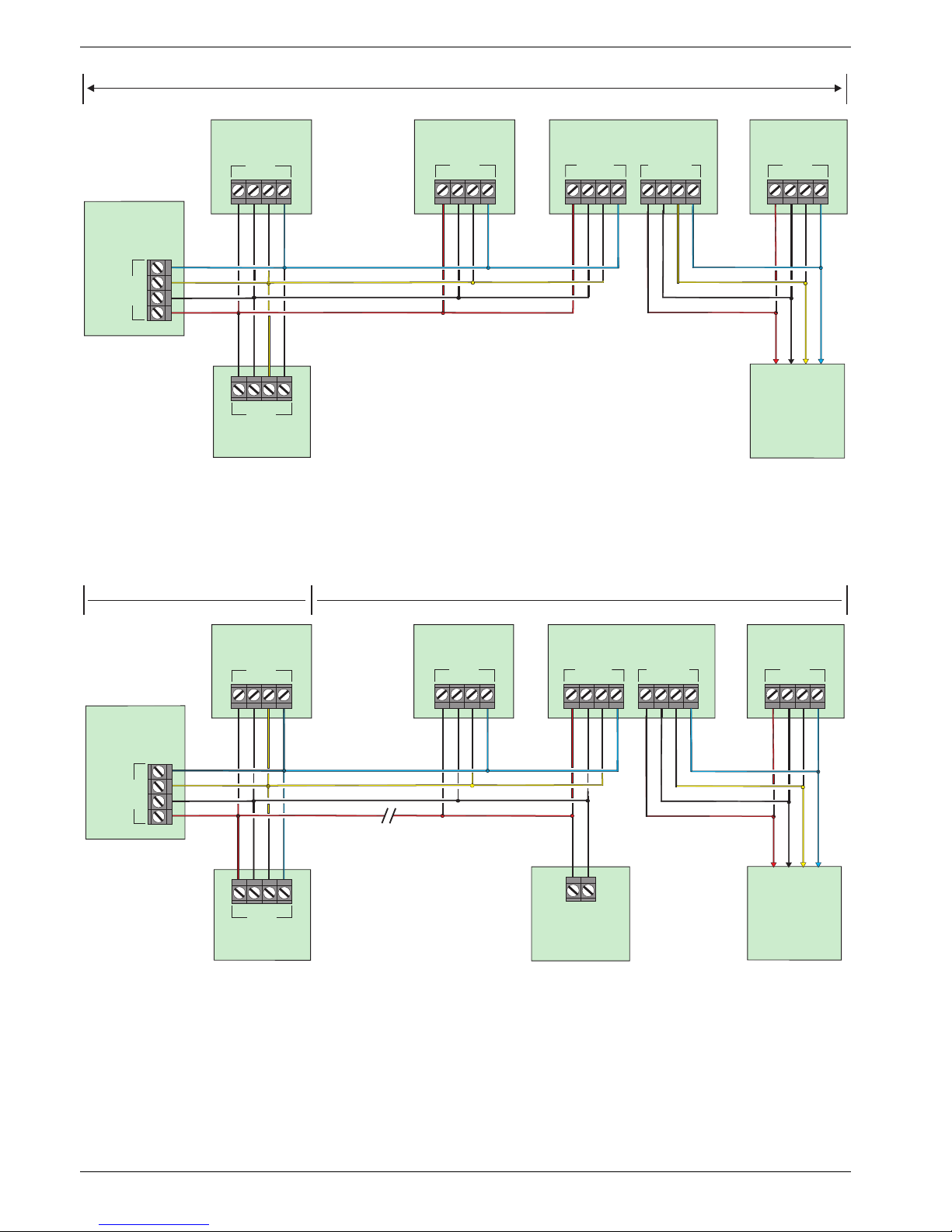
Keypads, zone expanders and output modules can all be
connected to any of the 8 sets of network terminals located at
the bottom of the control panel and may be connected serially
(daisy chain), in parallel (star) or any combination of the two (see
Figure 1, page 14 for details).
!
No more than 8 zone expanders, 8 keypads and 4 output
modules can be connected to each network.
Whenever new devices are connected to the networks, they
must be confirmed onto the system using the ‘Confirm
Devices’ menu option (see page 96 for details).
Wiring the Network
The networks are made up of four terminals incorporating
power and data. To ensure correct operation, all four
terminals on the device must be connected to the
corresponding terminals on the control panel, or previous
device (see Figure 1, page 14 for details). The table below
shows each terminal and its description:
Terminal Description
+ +12V Supply
- 0V Supply
T Transmit Data
R Receive Data
Devices can be connected using 4-core cable. However, it is
recommended that 6 or 8-core cable is used as the spare cores can
be used to ‘Double Up’ on the power connections if needed.
!
Standard 7/0.2 alarm cable can be used for most
installations. However, under certain conditions it may
be necessary to use screened cable.
Cable Distances
The maximum recommended distance for devices when
using standard 7/0.2 alarm cable is:
• 250m for each branch when using the star (parallel)
configuration
• When using a daisy chain (series) configuration the
maximum distance will depend on the number of devices
connected on the chain. The more devices that are
connected, the shorter the distance to the last device
(this is due to voltage drop in the cable)
Whichever method of wiring configuration is used, ensure
that the voltage between the ‘+’ and ‘–’ terminals at each
device is no lower than 10.0V when the system is running on
the standby battery.
The table below shows maximum cable runs when one
keypad or expander is installed using standard 7/0.2 alarm
cable with various loads:
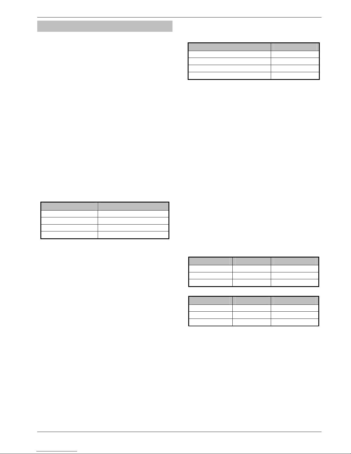
Configuration Max. Cable Run
1. Keypad + 2 PIR’s @15mA 250m
2. Expander + 2 PIR’s @15mA 250m
3. Expander + 8 PIR’s @15mA 100m
4. As No. 3 + 16Ω Speaker
30m
Distances of up to 1km can be achieved between the control
panel and a device. However, a power supply must be installed
close to the device to power it locally, this will help to
overcome voltage drop caused by the long cable run.
Overcoming Voltage Drop
There are several ways to overcome voltage drop:
• Use thicker lower resistance cable. Standard 7/0.2 alarm
cable has a resistance of 8Ω per 100m
• Double up on the power connections – this will require
using a 6 or 8-core cable rather than a 4-core cable
• Install a power supply to power the device locally,
remember to common the two negative connections
Installing a Power Supply
When a power supply is installed, the 0V connections on the
power supply must be connected through to 0V on the
control panel and the +12V connection between the control
panel and the device must be disconnected (see Figure 2,
page 14 for details).
Network Diagnostics
Each network has two LED’s to indicate data flow. The red
LED indicates data flowing out of the ‘T’ terminal and the
green LED indicates data flowing into the ‘R’ terminal. The
table below shows each LED status and its meaning:
LED Status ‘T’ Wire OUT ‘T’ Wire IN
Red LED Flashing Normal Normal
Red LED On Panel Fault Cable Short
Red LED Off Panel Fault Panel Fault
LED Status ‘R’ Wire OUT ‘R’ Wire IN
Green LED Flashing Panel Fault Normal
Green LED On Panel Fault Cable Short
Green LED Off Normal No Data From Devices
!
The LED’s are provided as an aid for fault finding and
therefore should not be completely relied upon to
indicate that there is a fault.
Page 14
Programming the Control Panel Premier 640 Installation Manual
14 INS344
Control Panel
Network 1 to 8
Premier
Keypad
+
TR
-
Network
Premier
Keypad
250 m
Premier
Zone Expander
+
TR
-
Network
+
TR
-
Network
+
TR
-
NETWORK IN
+
TR
-
NETWORK OUT
Premier
Output Module
+
TR
-
Network
Premier
Keypad
+
TR
-
Network
To additional
Keypads, Zone
Expanders or
Output Modules
Figure 1: Network Connections (250m without additional power supply).
250 m
Power
Supply
Disconnect
+12V from
control panel
+-
1 km
Control Panel
Network 1 to 8
+
TR
-
Network
+
TR
-
Network
+
TR
-
Network
+
TR
-
NETWORK IN
+
TR
-
NETWORK OUT
+
TR
-
Network
+
TR
-
Network
To additional
Keypads, Zone
Expanders or
Output Modules
Premier
Keypad
Premier
Keypad
Premier
Zone Expander
Premier
Output Module
Premier
Keypad
Figure 2: Network Connections (1km with additional power supply).
Page 15
Premier 640 Installation Manual Installation
INS344 15
Remote Keypads
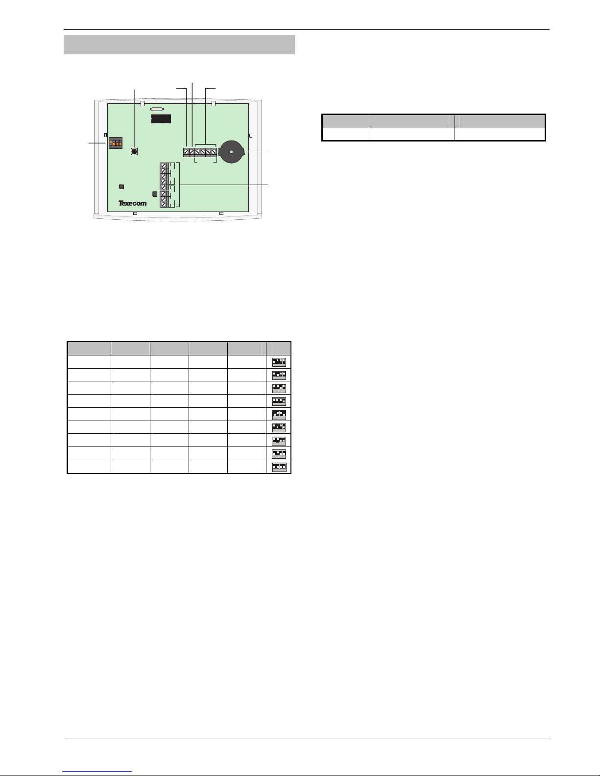
Keypad Layout
Zone 2
T
A
Zone 1
T
A
NETWORK
+
TR
-
O/P
Address
Switch
Output
Network
Terminals
Tamper
Switch
Speaker
Output
Zones
Piezo
Sounder
2431
On
SPK
Connecting Keypads
Keypads are connected to the network terminals located at
the bottom of the control panel (see pages 13 & 14 for
details).
Keypad Addressing
Each keypad must be assigned a different address using the
DIL switches located on the left hand side of the PCB. The
table below shows the keypad addressing:
Address DIL 1 DIL 2 DIL 3 DIL 4
1 On or off Off Off Off
2 431
2 Off On Off Off
2 431
3 Off Off On Off
2 431
4 Off Off Off On
2 431
5 On Off Off On
2 431
6 Off On Off On
2 431
7 Off Off On On
2 431
8 On Off On On
2 431
Engineers On On On On
2 431
!
Never set two keypads on the same network to the
same address.
When using a keypad as an Engineer’s keypad, the
DIL switches must all be ‘On’.
Keypad Zones
The keypad has two programmable zones (see page 21 for
details). Each zone is also fully programmable (see page 34
for details).
Keypad Output
The remote keypad has one programmable output, which
can be used to drive auxiliary devices such as LED’s,
sounders or relays etc. Wire as per Panel Outputs shown on
page 23 (see page 60 for details). The electrical
characteristics for the output are shown below:
Output Max Current Type
1 100mA Switched -ve
Keypad Speaker Output (LCDL/LCDLP Only)
The Premier LCDL and Premier LCDLP keypads have an
output that can be used for driving up to one 16Ω or two 8Ω
loudspeakers (see page 22 for details).
!
The speaker volume is also fully adjustable (see page
57 for details).
Programmable ‘Info.’ LED
The ‘Info.’ LED on the front of the keypad can be
programmed to mimic the keypad output or show the armed
status of an area (see page 57 for details).
Adjustable Backlighting
To adjust the keypad backlighting press the YES key for 5
seconds, then with the YES key still pressed use
%
to
increase or decrease the backlighting until the required
brightness is achieved, then release both keys.
!
The backlight can only be adjusted when the keypad is
not in a menu.
Keypad Lid Tamper
The lid tamper of each keypad can be disabled if required
using the relevant keypad option in the Keypad Setup menu
(see page 57 for details).
Page 16
Programming the Control Panel Premier 640 Installation Manual
16 INS344
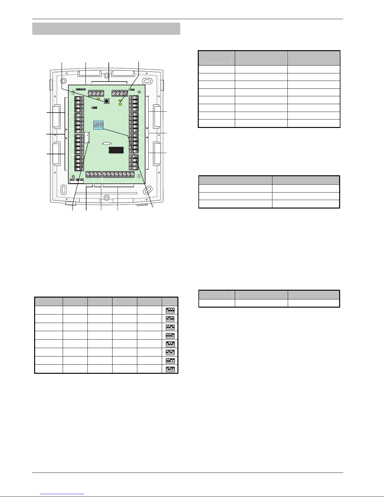
8XP Zone Expander
Expander Layout
Zones
5 & 6
Power LED
Tamper
Switch
Engineers
Keypad
Interface
Network
Terminals
Aux
12V
Aux
12V
Zones
7 & 8
Zones
1 & 2
Zones
3 & 4
Outputs
1 to 8
Speaker
Output
Aux
Input
Com Port
12
3
OUTPUTS
4
5
6
78
Zone 6
Zone 5
Aux 12v
-
Zone 8
Zone 7
T
A
T
A
T
A
T
A
NETWORK IN
+
-
TR
+
-
TR
NETWORK OUT
Remote
Power
Zone
2
Zone
1
TA
Aux 12v
-
+
Zone 4Zone 3
TATATA
Aux
Input
-
Spk
-
+
1ON2 3 4
PSU
D
S
YPE0123456
Tamper
Disable
Address
Switch
Connecting Expanders
Expanders are connected to the network terminals located at
the bottom of the control panel (see pages 13 & 14 for
details).
Expander Addressing
Each Expander must be assigned a different address using
the DIL switches located in the centre of the PCB. The table
below shows the expander addressing:
Address DIL 1 DIL 2 DIL 3 DIL 4
1 On or off Off Off Off
2 431
2 Off On Off Off
2 431
3 Off Off On Off
2 431
4 Off Off Off On
2 431
5 On Off Off On
2 431
6 Off On Off On
2 431
7 Off Off On On
2 431
8 On Off On On
2 431
!
Never set two expanders on the same network to the
same address.
Expander Zones
The expander has eight programmable zones (see page 21
for wiring details). Each zone is also fully programmable (see
page 34 for details).
Zone Numbering
The table below shows the zone allocation when the
expanders are installed:
Address
Zones
(Network 1)
Zones
(Network 2)
1 9 - 16 73 - 80
2 17 - 24 81 - 88
3 25 - 32 89 - 96
4 33 - 40 97 - 104
5 41 - 48 105 - 112
6 49 - 56 113 - 120
7 57 - 64 121 - 128
8 65 - 72 129 - 136
Expander Auxiliary Input
The expander has one programmable input. This auxiliary input
can be used to monitor auxiliary devices such as tamper loops
etc. Wire as per Aux Tamper shown on page 22 (see page 59
for details). The system will respond as follows:
Input Status System Response
0V Applied Input Secure
0V Removed Input Active
EOL Various *
!
For further details on how the input status affects the
system please refer to page 59.
* For wiring details, see page 24.
Expander Outputs
The zone expander has eight programmable outputs, which
can be used to drive auxiliary devices such as LED’s,
sounders or relays etc. Wire as per Panel Outputs shown on
page 23 (see page 60 for details). The electrical
characteristics for the outputs are shown below:
Outputs Max Current Type
1 to 8 100mA Switched -ve
Expander Speaker Output
The expander has an output that can be used for driving up to
one 16Ω or two 8Ω loudspeakers (see page 22 for details).
Expander Com Port
The Com Port can be used to connect a PSU200 montored
power supply or a RadioPlus Inteligent Receiver.
Expander Lid Tamper
The lid tamper of each expander can be disabled if required
by fitting a jumper link across the centre and right hand pins
of the ‘Enable Tamper’ pins (JP2) leaving the left hand pin
free. These pins are located to the left of the address DIL
switch just beneath the fuse.
Page 17
Premier 640 Installation Manual Installation
INS344 17
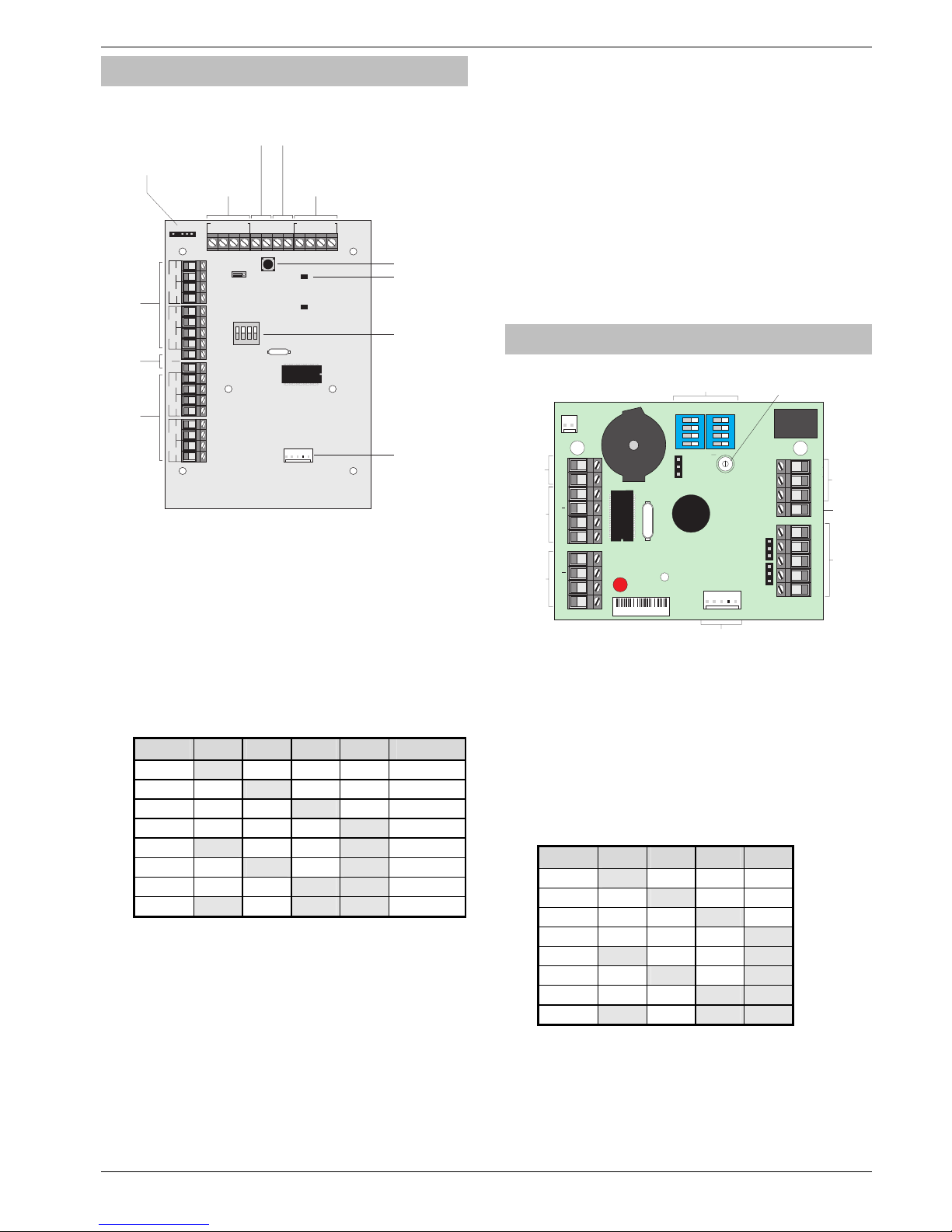
4 XP Zone Expander
Expander Layout
NETWORK IN
+
-
TR
+
-
TR
NETWORK OUT
JP1
Zone
2
Zone
1
TA
Aux 12v
-
+
Zone 4Zone 3
TATATA
1ON2 3 4
O/P
O/P
SPK+
SPK-
2- 1-
Engineers Keypad
JP4
D
S
JP2
Network IN
Terminals
Network OUT
Terminals
Outputs 1&2
Loud Speaker Terminals
Tamper Switch
Power LED
Address Switch
Zones
1 & 2
Zones
1 & 2
Aux 12V
Engineers Keypad
Interface
Com Port
Connecting Expanders
Expanders are connected to the network terminals located at
the bottom of the control panel (see pages 13 & 14 for
details).
Addressing
4XP expanders are addressed as one or (normally) two
keypads on the network. Each 4XP has to have a unique
address, which must not conflict with any keypad or any
other 4XP on the same network.
The following table shows the expander addresses & the
keypad slots that each would occupy.
Address
DIL 1 DIL 2 DIL 3 DIL 4 Keypads
1 On off off off 1 & 2
2 off On off off 2 & 3
3 off off On off 3 & 4
4 off off off On 4 & 5
5 On off off On 5 & 6
6 off On off On 6 & 7
7 off off On On 7 & 8
8 On off On On 8
Zones
The 4XP provides 4 alarm zones, 2 for each of the 2 keypad
slots it occupies. Each zone is fully programmable (see page
5.1 Zone Setup34) and has to be mapped to the system (see
Keypad Zone Mapping page 57).
Outputs
2 Programmable outputs are provided 1 for each of the 2
keypad slots occupied by the expander (see page 60 for
output programming)
Expander Speaker Output
One speaker output is provided for connecting one external
16Ω or 2 8Ω loudspeakers (see page 22 for details).
The speaker volume is programmed through the keypad setup
menu (see page 57)
!
The speaker is available on keypad 1 of the two
keypad slots the 4XP occupies. (ie if the 4XP address is
5, the speaker will programmed as belonging to
keypad 5).
Expander Com Port
The Com Port can be used to connect a RadioPlus
Inteligent Receiver.
iProx Module
iProx Layout
PIP0123456
Options
1
ON
2 3 4
1
ON
2 3 4
Address
RTE
N/C
N/O
Com
+
T
R
Spk
+
D0
D1
SW1 SW2
Internal
Sounder
Off
JP1
Ext
Int
Ext
Int
JP4
JP5
C1
L1-
C2
L2-
L+
Com1
Tamper
Option & Address Switches
Extension
Loudspeaker
Terminals
Wiegand
Interface
Connections
Network
Terminals
For Future Use
Remote
Prox Coil
Connections
Door Strike
Relay
Request to
Exit Input
Volume Adjustment
For Speaker
Connection
The iProx Module is connected to the network terminals
located at the bottom of the control panel (see pages 13 &
14 for details).
Addressing
The iProx Module is addressed as a keypad and will occupy
a keypad slot on the network. The unit must have a unique
address, which must not conflict with keypad or any other
iProx Module on the same network
The following table shows the addressing:
Address
DIL 1 DIL 2 DIL 3 DIL 4
1 On off off off
2 off On off off
3 off off On off
4 off off off On
5 On off off On
6 off On off On
7 off off On On
8 On off On On
Refer to the iProx Module manual for programming and
operating instructions.
Page 18
Programming the Control Panel Premier 640 Installation Manual
18 INS344
60IXD Zone Expander
The 60iXD expander provides the following facilities:
• Two iD loops each supporting up to 30 biscuits
• Fused 12V output for powering detectors
• Engineer’s keypad port for local iD diagnostics
!
The 60iXD expander module is only supported on Premier
640 control panels from version 1.0 onwards,
Installation
Before connecting the 60iXD expander module, isolate ALL
power from the control panel (AC mains and battery), do not
continue if there is still power present on the control panel.
1. Connect the iD expander to the control panel, see
60iXD installation manual (INS261) for details.
2. Connect the iD devices to the expander module, see
“iD Connections”.
3. Reapply power to the control panel and program the
necessary options on the panel see 60IXD
installation manual (INS261) for details.
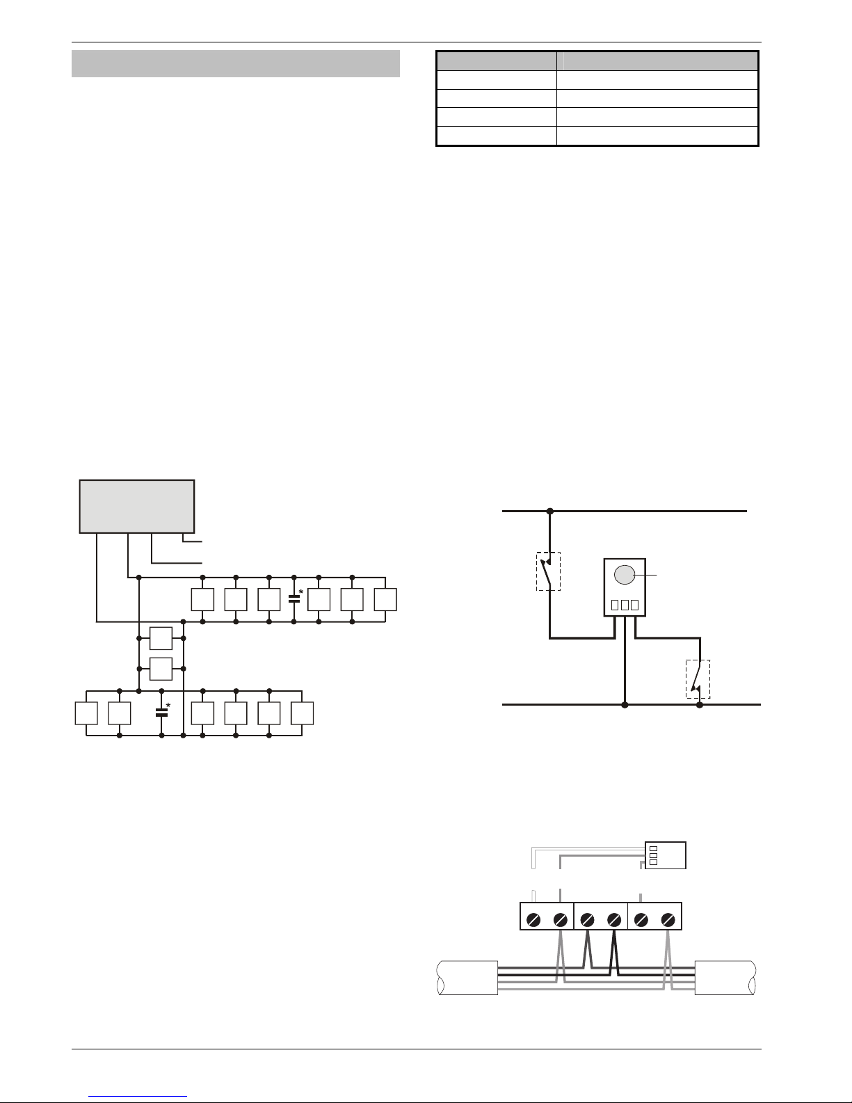
iD Connections
Each iD biscuit is connected across a two-wire detector loop.
Apart from observing the correct polarity, any wiring
configuration can be used, as shown in the diagram below:
60iXD
LOOP 1
+
-
09 10 11 12 13
03 04 05 0601 02
08
07
14
LOOP 2
+
-
As LOOP 1
* The 60iXD expander module is supplied with 4 off 10nF
capacitors in the spares pack. It is recommended that you
connect a 10nF capacitor approximately at the half way
point of each iD spur. It is especially important to do this on
iD spurs that are less than 30 metres.
Cabling Considerations
The iD loop can be wired using standard 4-core alarm cable,
this allows 2 cores to be used for the iD biscuit and 2 cores
for supplying 12V power for PIR's etc.
The number of biscuits that can be connected per cable run
is determined by the impedance of the cable used. Standard
4-core alarm cable (7/0.2mm) has a resistance of
approximately 8 Ohms per 100 metres. The following table
shows the maximum number of biscuits that can be
connected at the end of a single cable run using standard 4core alarm cable:
Cable Length Maximum Number of Biscuits
100m 30
200m 15
400m 7
800m 3
If a different type of cable is used, the distances should be recalculated. e.g., if 7/0.4mm cable is used, a single run of
200m would support 30 devices on the end as the resistance
of the cable is halved.
When installing the iD loop it is usually more practical to run
several cables from the expander module to the different
areas of protection. This effectively reduces any distance
problems and makes fault finding much easier.
To reduce the risk of induced interference and wherever
possible, cables should not be positioned along side mains
power, telephone or other data transmission cables, or run
within the same ducting or trunking as any other cables.
The wiring for the system’s internal sounders (loudspeakers)
should not be connected in the same multi-core as the iD
loop.
Biscuit Connections
Each iD biscuit is identified by its own number 01 to 30 and
contains its own internal sensor that is continuously
monitored by the expander module. The diagram below
shows the connections to the biscuit for monitoring both
tamper and alarm contacts.
iD Biscuit
Alarm
Ta m pe r
LOOP +
LOOP -
White
Ye ll ow
Blue
Biscuit iD
01
When the tamper switch is opened, the iD biscuit is taken
offline and a tamper condition is generated by the control
panel. If the alarm switch is opened the biscuit's internal
sensor changes state and the control panel will see this as an
active condition and will respond as appropriate.
The diagram below shows the typical wiring of a biscuit to a
standard PIR.
+12V
ALARM TAMPER
From Expander To next detector
Red
Black
Blue
Yellow
Red
Black
Blue
Yellow
White
Blue
Yellow
0V
“iD” is a registered trade mark of Chloride Safety System Limited.
Page 19
Premier 640 Installation Manual Installation
INS344 19
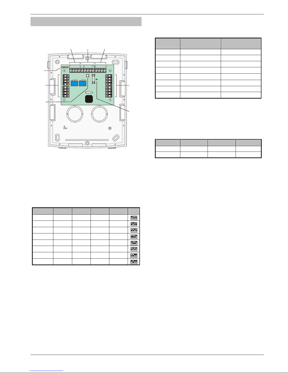
OP16 Output Expander
Output Module Layout
Powe r LED
Tam p er
Switch
Network
Ter m in a ls
A
ux 12V
and Tamper
Output
NETWORK IN
+
-
TR
+
-
TR
NETWORK OUT
Power
1Amp Aux 12v
1
A
mp
2431
BANK 1
Remote
Bank 2
Outputs
1 to 8
1
2
3
4
5
6
7
8
BANK 2
1
2
3
4
5
6
7
8
BANK 1
Bank 1
Outputs
1 to 8
Tmp
-
Aux 12V
++
-
2431
BANK 2
Network
Ter m in al s
Engineers
Keypad
Interface
Connecting Output Modules
Output modules are connected to the network terminals
located at the bottom of the control panel (see pages 13 & 14
for details).
Output Module Addressing
Each output module must be assigned a different address
using the DIL switches located in the centre of the PCB.
The table below shows the expander addressing:
Address DIL 1 DIL 2 DIL 3 DIL 4
1 On or off Off Off Off
2 431
2 Off On Off Off
2 431
3 Off Off On Off
2 431
4 Off Off Off On
2 431
5 On Off Off On
2 431
6 Off On Off On
2 431
7 Off Off On On
2 431
8 On Off On On
2 431
!
In order for an output module to mimic zone expander
outputs, the output module must be addressed the
same as the zone expander that it is mimicking.
Any combination of addresses can be used on each
output module i.e. Bank 1 can be addressed to mimic
expander 3 and Bank 2 can be addressed to mimic
expander 8.
Bank 1 switch sets the address of the device that Bank
1 outputs 1 to 8 will mimic.
Bank 2 switch sets the address of the device that Bank
2 outputs 1 to 8 will mimic.
Output Module Numbering
The table below shows the output allocation when the output
modules are installed:
Address
Outputs
(Network 1)
Outputs
(Network 2) **
1
Expander 1, 1 - 8 Expander 1, 1 - 8
2
Expander 2, 1 - 8 Expander 2, 1 - 8
3
Expander 3, 1 - 8 Expander 3, 1 - 8
4
Expander 4, 1 - 8 Expander 4, 1 - 8
5
Expander 5, 1 - 8 Expander 5, 1 - 8
6
Expander 6, 1 - 8 Expander 6, 1 - 8
7
Expander 7, 1 - 8 Expander 7, 1 - 8
8
Expander 8, 1 - 8 Expander 8, 1 - 8
Outputs
The output module has 16 programmable outputs, which can
be used to drive auxiliary devices such as LED’s, sounders or
relays etc. Wire as per Panel Outputs shown on page 23 (see
page 60 for details). The electrical characteristics for the
outputs are shown below:
Bank Outputs Max Current Type
1 1 to 8 100mA Switched -ve
2 1 to 8 100mA Switched -ve
Tamper Output
The tamper switch on the output module is connected to the
tamper output at the top of the module. If monitoring of the lid
tamper is required, this output must be connected to a
suitable input on the control panel or zone expander.
Page 20
Programming the Control Panel Premier 640 Installation Manual
20 INS344
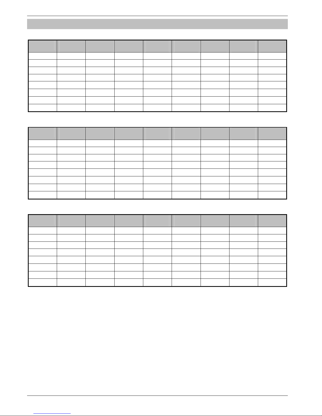
Zone and Output Numbering
Expander Zones
Address
Zones
Network 1
Zones
Network 2
Zones
Network 3
Zones
Network 4
Zones
Network 5
Zones
Network 6
Zones
Network 7
Zones
Network 8
1 1 - 8 65 - 72 129 - 136 193 - 200 257 - 264 321 - 328 385 - 392 449 - 456
2 9 - 16 73 - 80 137 - 144 201 - 208 265 - 272 329 - 336 393 - 400 457 - 464
3 17 - 24 81 - 88 145 - 152 209 - 216 273 - 280 337 - 344 401 - 408 465 - 472
4 25 - 32 89 - 96 153 - 160 217 - 224 281 - 288 345 - 352 409 - 416 473 - 480
5
33 - 40
97 - 104 161 - 168 225 - 232 289 - 296 353 - 360 417 - 424 481 - 488
6
41 - 48
105 - 112 169 - 176 233 - 240 297 - 304 361 - 368 425 - 432 489 - 496
7
49 - 56
113 - 120 177 - 184 241 - 248 305 - 312 369 - 376 433 - 440 497 - 504
8
57 - 64
121 - 128 185 - 192 249 - 256 313 - 320 377 - 384 441 - 448 505 - 512
Keypad Zones
Address
Zones
Network 1
Zones
Network 2
Zones
Network 3
Zones
Network 4
Zones
Network 5
Zones
Network 6
Zones
Network 7
Zones
Network 8
1 Unmapped Unmapped Unmapped Unmapped Unmapped Unmapped Unmapped Unmapped
2 Unmapped Unmapped Unmapped Unmapped Unmapped Unmapped Unmapped Unmapped
3 Unmapped Unmapped Unmapped Unmapped Unmapped Unmapped Unmapped Unmapped
4 Unmapped Unmapped Unmapped Unmapped Unmapped Unmapped Unmapped Unmapped
5
Unmapped Unmapped Unmapped Unmapped Unmapped Unmapped Unmapped Unmapped
6
Unmapped Unmapped Unmapped Unmapped Unmapped Unmapped Unmapped Unmapped
7
Unmapped Unmapped Unmapped Unmapped Unmapped Unmapped Unmapped Unmapped
8
Unmapped Unmapped Unmapped Unmapped Unmapped Unmapped Unmapped Unmapped
Expander/OP16 Outputs
Address
Outputs
Network 1
Outputs
Network 2
Outputs
Network 3
Outputs
Network 4
Outputs
Network 5
Outputs
Network 6
Outputs
Network 7
Outputs
Network 8
1 Exp. 1, 1-8 Exp. 1, 1-8 Exp. 1, 1-8 Exp. 1, 1-8 Exp. 1, 1-8 Exp. 1, 1-8 Exp. 1, 1-8 Exp. 1, 1-8
2 Exp. 2, 1-8 Exp. 2, 1-8 Exp. 2, 1-8 Exp. 2, 1-8 Exp. 2, 1-8 Exp. 2, 1-8 Exp. 2, 1-8 Exp. 2, 1-8
3 Exp. 3, 1-8 Exp. 3, 1-8 Exp. 3, 1-8 Exp. 3, 1-8 Exp. 3, 1-8 Exp. 3, 1-8 Exp. 3, 1-8 Exp. 3, 1-8
4 Exp. 4, 1-8 Exp. 4, 1-8 Exp. 4, 1-8 Exp. 4, 1-8 Exp. 4, 1-8 Exp. 4, 1-8 Exp. 4, 1-8 Exp. 4, 1-8
5
Exp. 5, 1-8 Exp. 5, 1-8 Exp. 5, 1-8 Exp. 5, 1-8 Exp. 5, 1-8 Exp. 5, 1-8 Exp. 5, 1-8 Exp. 5, 1-8
6
Exp. 6, 1-8 Exp. 6, 1-8 Exp. 6, 1-8 Exp. 6, 1-8 Exp. 6, 1-8 Exp. 6, 1-8 Exp. 6, 1-8 Exp. 6, 1-8
7
Exp. 7, 1-8 Exp. 7, 1-8 Exp. 7, 1-8 Exp. 7, 1-8 Exp. 7, 1-8 Exp. 7, 1-8 Exp. 7, 1-8 Exp. 7, 1-8
8
Exp. 8, 1-8 Exp. 8, 1-8 Exp. 8, 1-8 Exp. 8, 1-8 Exp. 8, 1-8 Exp. 8, 1-8 Exp. 8, 1-8 Exp. 8, 1-8
Page 21
Premier 640 Installation Manual Installation
INS344 21
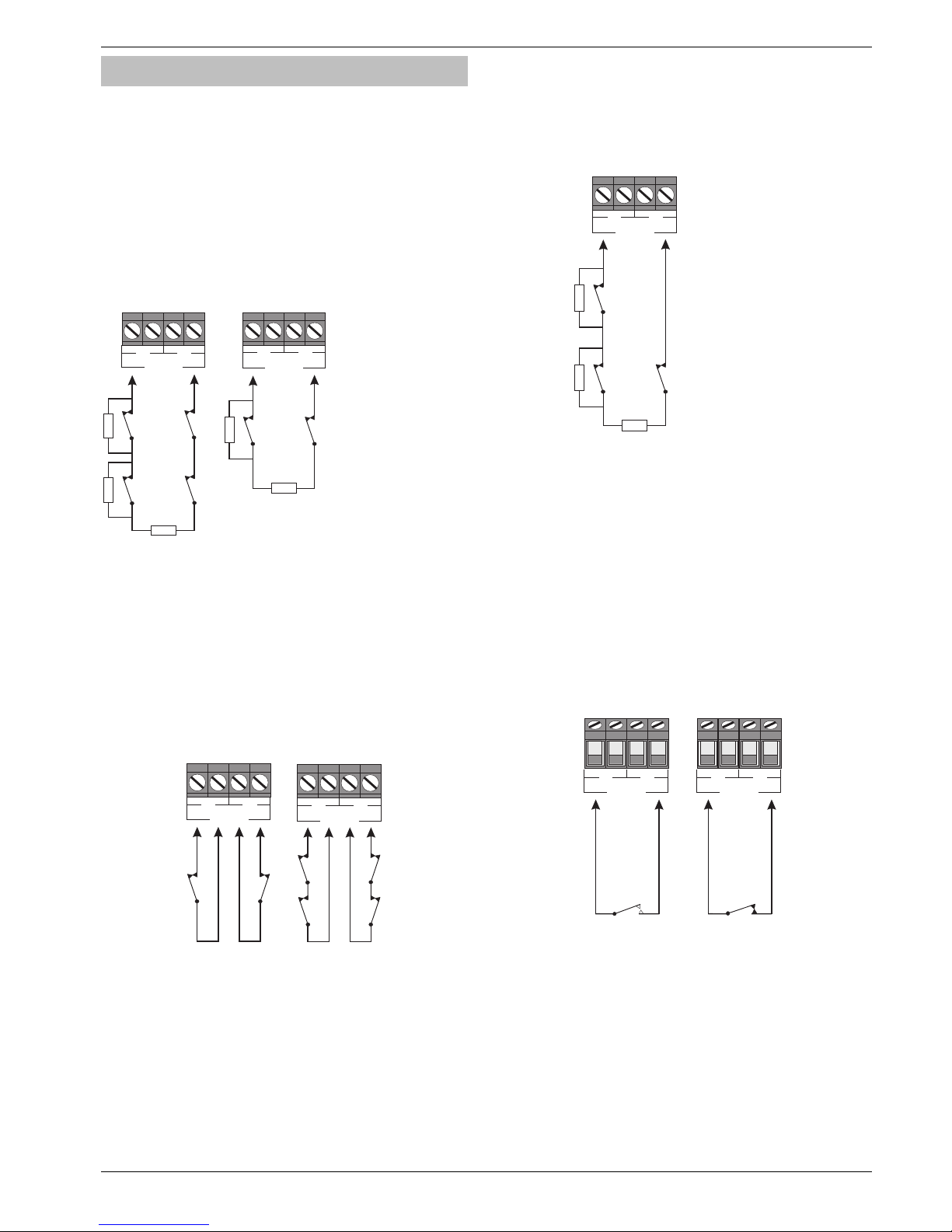
Zone Connections
Any zones that are not being used must be linked out or
programmed as ‘Not Used’ (see page 34 for details).
When using End Of Line wiring, only 1 device should
normally be connected to each zone.
A zone short can be programmed for ‘Active’ or ‘Tamper’
response (see page 50 for details).
End Of Line (EOL)
Use this wiring configuration when connecting normally
closed detection devices to the zone using 2-Wires. Zone
wiring should be programmed as Double Pole/EOL (see
Zone Wiring page 38)
Alarm
Tamper
E.O.L
2k2W
4k7W
Alarm
Tamper
2 Normally
Closed Devices
1 Normally
Closed Device
Tamper
E.O.L
Alarm
Zone 1
T
A
TA
Zone 1
4k7W
4k7W
2k2W
Alarm Contact Resistor = 4K7
EOL Resistor = 2K2
!
When using this configuration, no more than 3 detectors
can be connected to each zone.
Double Pole
Use this wiring configuration when connecting normally
closed or normally open detection devices to the zone using
4-Wires. Zone wiring should be programmed as Double
Pole/EOL (see Zone Wiring page 38)
!
When using this configuration, no more than 10
detectors can be connected to each zone.
Triple End Of Line (TEOL)
Use this wiring configuration when connecting PIR devices
with that require Anti Mask and Fault detection. Several zone
wiring programming options are available for this, Triple EOL
is illustrated below. See Zone Wiring on page 38.
!
When using this configuration, only 1 detector can be
connected to each zone.
!
Alternative resistor values are available – see Zone
Wiring on page 38 for more details.
Normally Open Or Normally Closed Circuits
This wiring configuration is normally used for key switches
with a N/O or N/C contact. Zone wiring options are provided
for each.
Testing Zones
To test zones prior to commissioning, use the View Zone
Status option in Engineers Utilities see page 95.
1 Normally
Closed Contact
Zone 1
T
A
2 Normally
Closed Contacts
TA
Zone 1
1 Normally Closed Device
with Fault and Mask
(Mask = Fault + Alarm)
E.O.L
Alarm
TA
Zone 1
4k7W
2k2W
Tamper
Fault
2k2W
Alarm contact resistor = 4K7
Fault contact resistor = 2K2
EOL resistor = 2K2
Normally Open
Contact
Zone 1
T
A
Normally Closed
Contact
Zone 1
T
A
Page 22
Programming the Control Panel Premier 640 Installation Manual
22 INS344
.
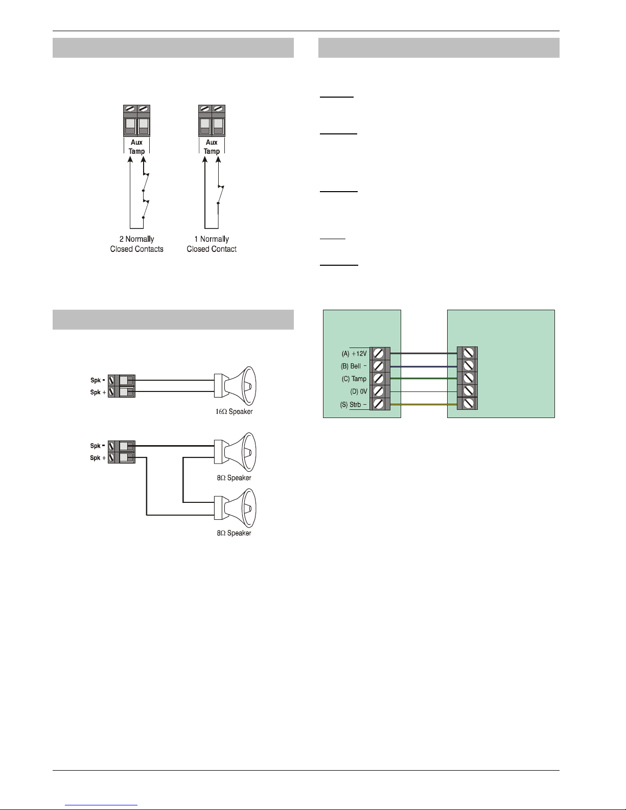
Auxiliary Tamper Connections
The Auxiliary Tamper terminals allow the control panel to
monitor the tamper loops of external devices such as power
supplies etc.
!
If the ‘Auxiliary Tamper’ terminals are not being used
they must be linked out.
Speaker Connections
This output can be used for driving up to one 16Ω or two 8Ω
loudspeakers as shown below:
!
For details on testing Speaker outputs, see page 94.
External Sounder Connections
The following terminals have been provided for connection to
an external sounder:
(A)
+
12V
12V supply (protected by a 1A fuse F4). Normally connected
to ‘+12V’ on the sounder.
(B) Bell –
Sounder output, switches to 0V in alarm (SAB) and is rated at
500mA. Normally connected to Trigger -ve on
the sounder. This output can also be programmed for SCB
operation (see page 48 for details).
(C) Tamp
Negative tamper return. Normally connected to ‘Tamper Out’
on the sounder. If this terminal is not being used, it ust be
connected to ‘0V’.
(D) 0V
0V supply. Normally connected to ‘0V’ on the sounder.
(S) Strb –
Strobe output, switches to 0V in alarm and is rated at 500mA.
Normally connected to strobe -ve on the sounder (where
applicable, connect the strobe +ve to +12V).
Te xec o m E xte r n a l
Sounder
Control
Panel
+12V (A)
0V (D)
Tam p e r ( C )
Strobe -ve (S)
Trigger -ve (B)
!
For details on testing the ‘Bell’ outputs, see page 94.
Page 23
Premier 640 Installation Manual Installation
INS344 23
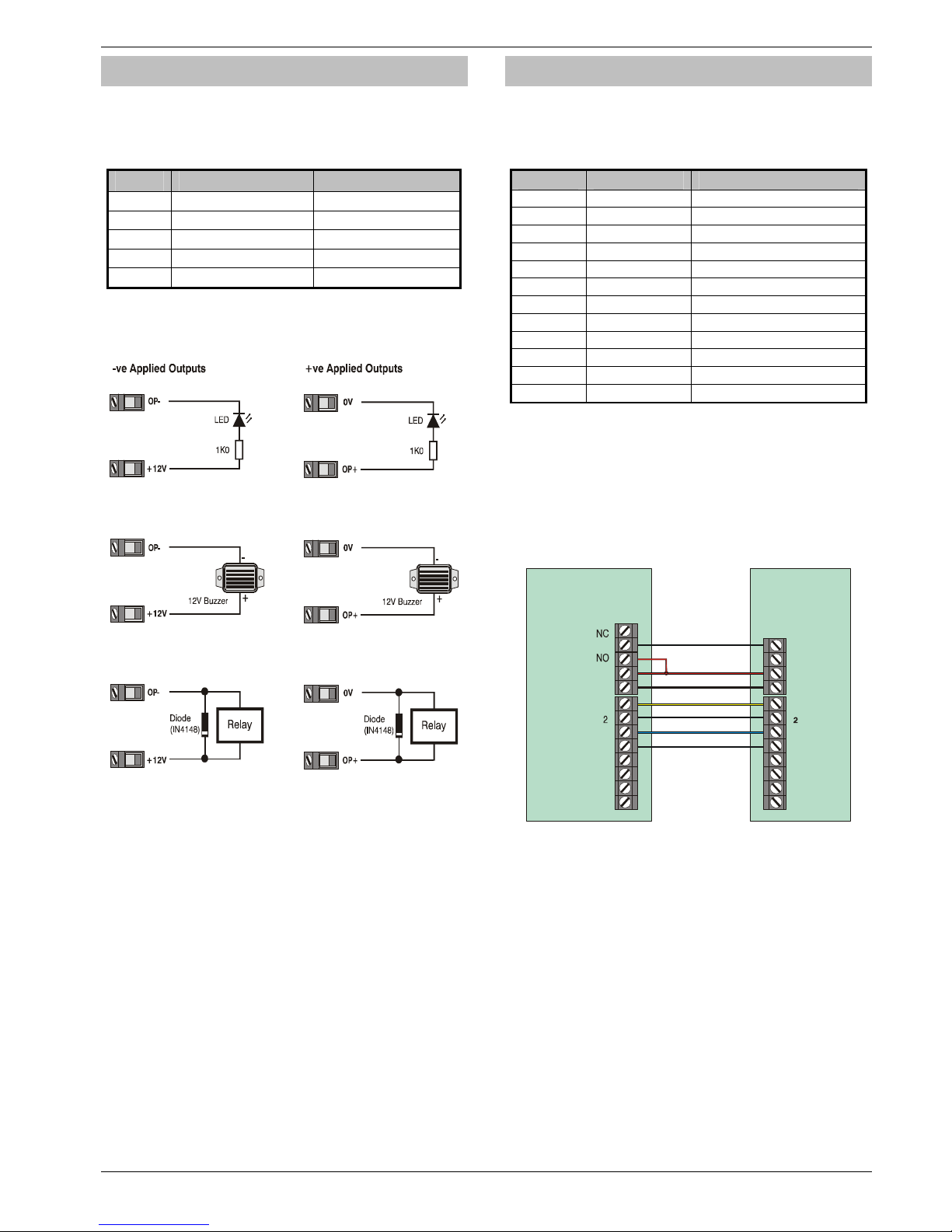
Panel Outputs 1 - 5
The control panel has five programmable outputs, which can
be used to drive auxiliary devices such as LED’s, sounders or
relays etc. (see page 60 for details). The table below shows
the electrical characteristics for each output:
No Max Current Type
1 1A Switched -ve
2 1A Switched -ve
3 1A Switched +ve
4 1A Switched +ve
5 3A Relay
Wiring Outputs
The diagram below shows some typical wiring examples:
!
For details on testing outputs, see page 94.
Digicom Outputs 1 - 8
The control panel has eight programmable outputs, which
can be used for connecting to a stand-alone communicator
(see page 61 for details). The table below shows the electrical
characteristics for each output:
Terminal Max Current Operation
1 100mA Switched 0V
2 100mA Switched 0V
3 100mA Switched 0V
4 100mA Switched 0V
5 100mA Switched 0V
6 100mA Switched 0V
7 100mA Switched 0V
8 100mA Switched 0V
L/M N/A 12V applied = Line Fault *
R/R N/A 0V applied to reset
DC+ N/A +12V Power (unfused)
DC- N/A 0V Power
* Control Panel Line Fault Input (L/M)
In accordance with BSIA form 175, the line fault input on the
control can detect a single or a dual line fault for use with the
ATS Remote Test output type
Wiring a Stand Alone Communicator
The diagram below shows a typical wiring example:
Control
Panel
Power
1
3
4
5
6
7
8
12V
0V
Stand Alone
Communicator
C
DC +
L / M
R / R
DC -
1
3
4
5
6
7
8
Channel Inputs
Programmed
as Positive
Removed
Line Fault
Digicom
Outputs
!
For details on testing the digicom outputs, see page
94.
Page 24
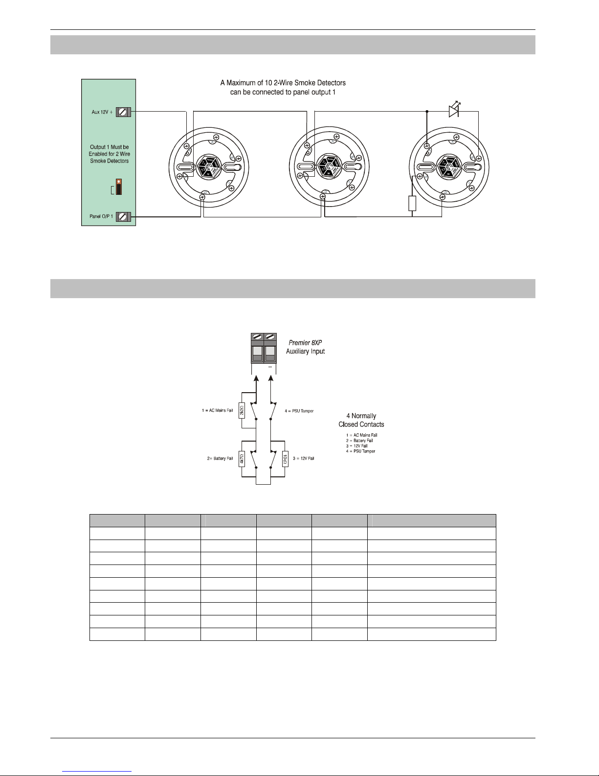
Programming the Control Panel Premier 640 Installation Manual
24 INS344
2-Wire Smoke Detector
Panel Output 1 can be used for connecting up to 10, 12V 2-Wire smoke detectors.
Enable
Smoke
+V In
+V Out
OV
-RLED
+V Out
OV
-RLED
+V In
+V Out
OV
-RLED
1k EOL
Remote LED
(Optional)
+V In
Control
Panel
To enable 2-Wire smoke detection on panel output 1, a jumper link must be fitted across the bottom two pins of JP6. The Area
Option ‘2-Wire Smoke’ also needs to be enabled (see page 45).
!
2-Wire smoke detectors can only be connected to panel output 1.
Expander Auxiliary Input
This input can be used for monitoring a remote power supply that has a voltage free output for the following three conditions: AC Mains
Fail, Battery Fail, 12V Fail and Tamper.
Aux
Input
When the Auxiliary Input is programmed as ‘PSU Monitor’ the system will respond as follows:
Tamper 12V Fail Battery Fail A/C Fail Resistance Response
Closed Closed Closed Closed 0R No Faults
Closed Closed Closed Open 2K2 AC Fail
Closed Closed Open Closed 4K7 Battery Fail
Closed Closed Open Open 6K9 Battery Fail + AC Fail
Closed Open Closed Closed 10K 12V Fail
Closed Open Closed Open 12K2 AC Fail + 12V Fail
Closed Open Open Closed 14K7 Battery Fail + 12V Fail
Closed Open Open Open 16K9 AC Fail + Battery Fail + 12V fail
Open - - - O/C Lid Tamper
Page 25
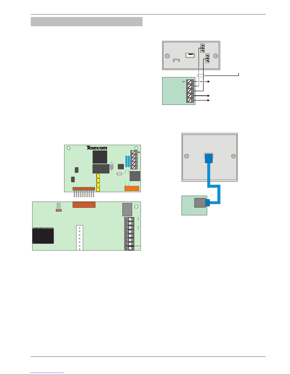
Premier 640 Installation Manual Installation
INS344 25
Plug-on Communicators
The Com300 is a multi format 8-channel digital
communicator/300-baud modem for use with a standard
analogue telephone line.
The Com2400 is a multi format 8-channel digital
communicator/2400-baud modem for use with a standard
analogue telephone line in addition, this modem can also send
Short Message Service (SMS) text messages to a mobile
phone.
The ComISDN is a multi format 8-channel digital
communicator/modem for use with an ISDN telephone line.
These Communicators can be used to report system events to
an Alarm Receiving Centre using Fast Format, Contact ID or
SIA Level II or to upload/download control panel information
using the Wintex UDL software and a PC.
Plugging on the Communicator
Ensure that the board is the correct way up (see below).
Locate the plug into the communicator socket on the control
panel and line up the mounting holes with the pillars in the
base. Once all the holes line up, press down gently until the
pillars snap into the holes.
OP1-
OP5
N/O COM N/C
Spk
-
Top Right Hand Corner Control PanelPremier 640
Box
Tamp
OP2-
OP3+
OP4+
T
R
T1
R1
Standard Telephone Line Connections
A standard telephone line must be connected to the Com300
or Com2400 communicator as shown below:
R1
R
T
T1
To other telephone
extension sockets
Com300
Com2400
or
Master
Socket
T = 5 or A - White/Blue ring
R = 2 or B - Blue/White ring
3
2
1
6
5
4
Telephone cable
Type 1/0.5mm CW1308
This terminal must be connected to
the incoming AC Mains earth supply
ISDN Telephone Line Connections
An ISDN telephone line must be connected to the ComISDN
communicator as shown below:
ComISDN
ISDN
Te rm i n al
RJ45
Lead
!
For details on testing the communicators, see page 67.
Page 26

Programming the Control Panel Premier 640 Installation Manual
26 INS344
RP9 Radio-Pad
Before connecting the Radio-Pad, isolate ALL power from the
control panel (AC mains and battery), do not continue if there
is still power present on the control panel.
To install the Radio-Pad onto the control panel:
• Connect the Molex connector of the RPD-Com lead to
Com2 on the control panel
• Connect the 25-Way D-Type connector of the RPD-Com
to the Radio-Pad
• Locate the power lead connector into the socket at the
bottom of the Radio-Pad
• Connect the Black lead to the DC- terminal on the control
panel
• Connect the lead with the White stripe to the DC+
terminal on the control panel
• Follow the procedure for Registering the Radio-Pad
Registering the Radio-Pad
Whenever a Paknet Radio-Pad is installed or moved, it must
be registered onto the network. To do this:
• Press and hold the test button on the front of the Paknet
Radio-Pad
• With the test button still pressed, connect power to the
control panel and wait for the yellow service light on the
Radio-Pad to flash
• Release the test button
Within 2 minutes the yellow service light should stop flashing
and remain steady. This means that the Paknet Radio-Pad
has now selected and locked on to the Base Station with the
strongest signal.
The Paknet Radio-Pad should be re-registered on every site
visit, this is to ensure that any new Vodafone Packet Radio
Service Base Stations in the vicinity are recorded by the
Paknet Radio-Pad.
Programming the Radio-Pad
• Program Com 2 for Radio-Pad operation (see page 76
for details)
• Refer to the Radio-Pad installation guide for full
programming details.
GSM Module
Before connecting the GSM Module, isolate ALL power from
the control panel (AC mains and battery), do not continue if
there is still power present on the control panel.
To install the GSM Module onto the control panel:
• Connect the Molex connector of the GSM-Com lead to
Com2 on the control panel
• Connect the RJ45 connector of the GSM-Com to the
GSM Module
• Locate the power Jack Plug into the socket at the bottom
of the GSM Module
• Insert a SIM card into the bottom of the GSM Module
• Connect power to the control panel
Programming the GSM Module
• Program Com 2 for GSM Module operation (see page 76
for details)
• Refer to the GSM Module installation guide for full
programming details.
AV Module
Before connecting the AV Module, isolate ALL power from the
control panel (AC mains and battery), do not continue if there
is still power present on the control panel.
To install the AV Module onto the control panel:
• Connect one end of the patch lead on to the Expansion
Port of the AV Module
• Connect one other end of the patch lead on to the
Expansion Port of the control panel
Programming the AV Module
• Program the Expansion Port for AV Module operation
(see page 76 for details)
• Refer to the AV Module installation guide for full
programming details.
ComIP Module
Before connecting the ComIP Module, isolate ALL power from
the control panel (AC mains and battery), do not continue if
there is still power present on the control panel.
To install the ComIP onto the control panel:
• Connect one end of the patch lead on to JP1 of the
ComIP
• Connect one other end of the patch lead on to Com1 or
2 of the control panel
Programming the ComIP Module
• Program Com1 or 2 for ComIP Module operation (see
page 76 for details)
• Refer to the ComIP Module installation guide for full
programming details.
Page 27
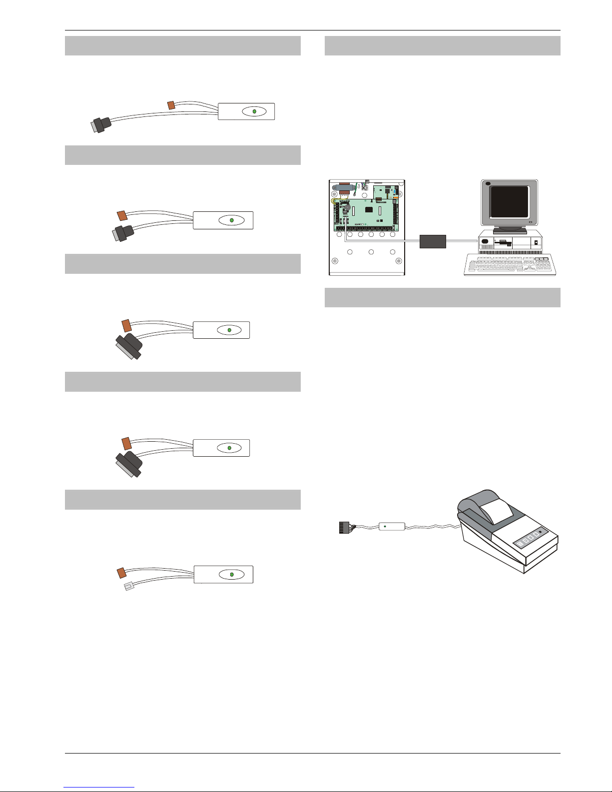
Premier 640 Installation Manual Installation
INS344 27
PC-Com
The PC-Com has two connectors. The 9-way D-type connector is
for connection to a serial port on a computer and the Molex
connector plugs onto Com 1 on the control panel.
UNI-Com
The UNI-Com has two connectors. The 9-way D-type
connector connects to any supported serial device, the Molex
connector plugs onto Com 1 on the control panel.
PRINT-Com
The PRINT-Com has two connectors. The 25-way D-type
connector connects to a Serial Printer and the Molex
connector plugs onto Com 1 on the control panel.
RPD-Com
The RPD-Com has two connectors. The 25-way D-type
connector connects to a Paknet Radio-Pad and the Molex
connector plugs onto Com 2 on the control panel.
GSM-Com
The GSM-Com has two connectors. The RJ45 connector connects
to a GSM Module, the Molex connector plugs onto Com 2 on the
control panel.
Connecting a Computer
The Premier 640 supports local uploading and downloading
between the control panel and a PC running Wintex UDL
software. Uploading and Downloading can be used to
program and interrogate the control panel.
In order for the computer to work correctly, ensure that it is
set to the following:
• UDL Password (see page 73 for details)
!
In order to upload and download to the control panel
locally, a PC-Com lead is required.
PC-Com
Com 2
F1
F2
F4
F5
Box
Tamp
JP7
Aux 12v 1Amp
Network 2
1Amp
Engineer Remo t e
Com 1
Heartbeat
JP2
JP5
Jp9
Load
Defaults
Expansion
JP6
F3
Network 1
1Amp
Connecting a Printer
The Premier 640 supports printer facilities. The printer is
connected to the Com 1 connector located on the control
panel and can be used to print the control panel event log.
In order for the printer to work correctly, ensure that it is set to
the following:
• Baud Rate = 4800
• Parity = None
• Start Bits = 1
• Stop Bits = 2
• Data Bits = 8
• DTR = Normal
• Columns = 40 or 80 (see page 50)
!
In order to connect a printer to the control panel, a
PRINT-Com lead is required.
DATAC or RS232 printer
RS232 Data
Connect to
COM1
PRINT-Com
Page 28
Commissioning and Troubleshooting Premier 640 Installation Manual
28 INS344
4. Commissioning and Troubleshooting
Commissioning
Once ALL connections have been made to the control panel
and power is ready to be applied, you should read this
section before continuing.
When applying power for the first time, the factory default
settings must be loaded. The default settings ensure that
the control panel software is reset and all programming
information is loaded into memory.
The factory default settings are loaded by applying power to
the control panel whilst at the same time, holding down the
Factory Default button.
To default the control panel, proceed as follows:
• Connect the black battery lead to the negative (–)
terminal of the standby battery and the red battery lead to
the positive (+) terminal of the standby battery
• Press and hold the Factory Default button
• Press the battery kick-start button to connect the battery
and ensure that the green heartbeat light illuminates
• After the heartbeat light has illuminated, let go of the
Factory Default button (the heartbeat light will continue
to flash whilst the factory default settings are being
loaded, this can take up to 30 seconds)
• If the system goes into alarm, enter the default
Engineer code
!"#$
, and the alarm
tone will stop
• To access the Engineer Programming Menu, enter the
default Engineer code
!"#$
• Program the system as described in section 6
(Programming the Control Panel)
• Perform a zone test as described on 94. Remember that
some powered detectors (e.g. PIR’s and combined
technology detectors) take several minutes to warm up
and become operational
• Test the internal sounder, external sounder and strobe as
described on page 95
• Replace the lid and secure with the lid screw supplied
• Press
&
followed by YES to leave the programming
menu, the system will return to normal
• The display will be showing that there is a ‘Mains Power
Off’ condition. Switch on the AC mains supply to the
control panel
• The normal banner message (if programmed) will now
be displayed
Installation is now complete and the system is
ready for use.
Trouble-Shooting
Control Panel
No Power to unit (mains only)
•
Check the mains block fuse and replace if blown
• Check for loose wires at the mains block, the transformer
and the AC terminals on the PCB
• Check the mains block is connected correctly; live to live
(brown), neutral to neutral (blue)
No Power to unit (battery only)
•
Don’t forget to press the battery kick-start button
• Check the battery fuse F2 and replace if blown
• Check for loose wires at the BATT terminals on the PCB
• Check that the battery wires are connected correctly; red
from BATT+ to the battery positive (+), black from BATTto the battery negative (-)
Heartbeat LED is not flashing
•
Remove ALL power (AC Mains and Battery) and then
reapply power again
Network Data LED’s are not flashing
•
Remove ALL power (AC Mains and Battery) and remove
ALL wires from the network terminals. Then
re-apply power again before referring to the Network
Diagnostics table on page 13
Keypads
Keypad does not operate
•
Check that the keypad is wired correctly from the control
panel (see page 13 for wiring details)
• Check the network fuses F3 and F5 and replace if blown
• Use the network diagnostics (see page 13 for details)
Keypad does not accept codes
•
If the system has more than one keypad check that each
keypad is addressed differently, see page 15 for details
• If the keypad is on a long cable run, check the voltage
between the ‘+’ and ‘–’ terminals at the keypad and
ensure that it measures no less than 10.0V
• Check that you are using the correct User codes. The
default Engineer code is
!"#$
and the
default Master User code is
'()*+
• Check that the User code you are using is not ‘Time
Locked’, if the User code is time locked then the access
code will only be accepted when the Control Timer is off
(see pages 52 and 88 for details)
Keypad zones do not operate
•
Each keypad zone has to be mapped onto the system
before it can be used (see page 57 for details)
• The zone is not programmed (see page 34 for details)
Keypad emergency keys do not operate
•
Each keypad can be configured so that the emergency
keys PA, FIRE and MEDICAL can be enabled or
disabled. Check that the keypad has been programmed
correctly (see page 57 for details)
Page 29

Premier 640 Installation Manual Commissioning and Troubleshooting
INS344 29
Expander
Expander does not operate at all
•
Check that the expander is wired correctly from the
control panel (see page 13 for wiring details)
• Check the network fuses F3 and F5 and replace if blown
System does not recognise zones
•
If the expander is on a long cable run, check the voltage
between the + and – terminals at the expander and
ensure that it measures no less than 10.0V
The speaker output does not work
•
The expander can be configured so that Alarm, Entry,
Exit, Chime tones etc. can be enabled or disabled. Check
that the expander has been programmed correctly (see
page 59 for details)
• The speaker volume on the expander is electronically
adjustable. Check the volume is set to the desired level
(see page 59 for details)
Zones
One or more zones show an alarm
•
Check that the zone is wired correctly (see page 21 for
wiring details)
Communicator
The Communicator will not dial
•
By default the communicator is disabled, check that the
communicator is enabled (see page 71 for details)
• Check that the telephone line has been correctly wired to
the communicator (see page 25 for wiring details)
• Check that the telephone numbers are programmed
correctly (see page 70 for details)
• Check that the account numbers are programmed
correctly (see page 70 for details)
• Check that the dial attempts are not programmed as zero
(see page 70 for details)
• Check that the reporting areas have been programmed
correctly (see page 70 for details)
• Check that the reporting options have been programmed
correctly (see page 70 for details)
Communicator dials but does not communicate
•
Check that the telephone numbers are programmed
correctly (see page 70 for details)
• Check that the correct protocol is programmed (see
page 70 for details)
Operation
The system will not allow me to arm
•
Check that there are no outstanding problems (see page
30 for details)
• Check that there are no outstanding alarms that require
resetting
• Check that the User code has been programmed to
allow arming (see page 86 for details)
• Check that the User code has been assigned to the
correct areas (see page 85 for details)
• If a ‘Local’ User code is being used (see page 86 for
details) ensure that the keypad being used is assigned to
the correct area (see page 56 for details)
The system will not allow me to disarm
•
Check that the User code has been programmed to
allow disarming (see page 86 for details)
• Check that the User code has been assigned to the
correct area(s) (see page 85 for details)
• If a ‘Local’ User code is being used (see page 86 for
details) ensure that the keypad being used is assigned to
the correct area (see page 56 for details)
Page 30
Factory Defaults Premier 640 Installation Manual
30 INS344
Reset and Service Messages
When the system requires attention because of a potential
problem, the display will show one of three service
messages. These messages can also be accessed at any
time, allowing the user to view installer information.
!
These messages would normally be programmed with
the telephone numbers of the installer or the Alarm
Receiving Centre (see page 53 for details).
To display the service messages, proceed as follows:
The display will normally show the time and date:
!!!!
!"#$!%&!'()!*%%+
Press
,
followed by ! for the Service message:
,(--!.-()/!,01
!!20)!3$)456$
Press
,
followed by " for the Reset message:
,(--!78958$$)!:0
!!;$<$:!3=<:$/
Press
,
followed by # for the Anti-code message:
,(--!.;,!:0
;$<$:!3=<:$/
Press
-
to exit from the message, the display will then
return to normal.
When alarm information is being displayed, pressing the
SCROLL key will slow down the display and also allow
manual scrolling through the events.
Fault Warning Tones
When a fault condition occurs i.e. mains fail, line fault etc.
the internal sounders will chime every 30 seconds for 3
minutes. The chiming will automatically stop when a valid
User code is entered, when - is pressed or after 3
minutes (whichever occurs first). The fault indication will only
be cleared from the display when the fault has been rectified
i.e. power, telephone line has been restored.
Fault Messages
!3>3"7'!.?7;"3@
!"#$!%&!'()!*%%A
There are system faults waiting to be
viewed, enter a valid user code to view
the faults. After entering a code faults will
be displayed for 30 seconds. If the fault is
not reset within 30 seconds, this
message will be displayed again.
,08B5)/!C$456$<
!"#$!%&!'()!*%%+
The number of devices connected to the
networks has changed from the last time
a ‘Confirm Devices’ was done.
>0#!8$$D!(!#<$)
:0!$8(E-$!(66$<<
Engineer access is programmed for
Engineer code + User code (see page
49 for details).
>0#!8$$D!(!#<$)
:0!#8()/!<=<:$/
The Engineers code was entered when the
system was fully armed (access to the
programming menu can only be gained
when the system is not fully armed.
.-()/!78958$$)
F0)G589!H8!35:$
The alarm engineer has logged into the
programming menu and is working on
site (this message will clear when the
engineer logs off or the system is armed).
'(58<!I0J$)!HBB
!"#$!%&!'()!*%%+
There has been an AC Mains failure.
."3!I(:K!2(#-:
!"#$!%&!'()!*%%+
There is a fault with the ATS (Alarm
Transmission System).
L0!I(:K!.4(5-(E-$
!"#$!%&!'()!*%%+
There are no ATS (Alarm Transmission
System) paths available.
!M!LH!N.""7;>!M
!"#$!%&!'()!*%%+
The Standby Battery has not been
connected,
N(::$)=!2(#-:
!"#$!%&!'()!*%%+
There is a fault with the control panel
standby battery or it is not connected.
.)$(!2(5-$D!"$<:
!"#$!%&!'()!*%%+
Zones that have been placed on test
have failed the test.
I(8$-!?5D!"(/O$)
!"#$!%&!'()!*%%+
There is a fault with the control panel lid
tamper.
N$--!"(/O$)
!"#$!%&!'()!*%%+
There is a fault with the bell tamper on
the control panel.
.#P5-5()=!"(/O$)
!"#$!%&!'()!*%%+
There is a fault with the auxiliary tamper
on the control panel.
N$--!2#<$!N-0J8
!"#$!%&!'()!*%%+
The bell fuse on the control panel has
blown.
.#P1!2#<$!N-0J8
!"#$!%&!'()!*%%+
The Auxiliary fuse on the control panel
has blown.
;QI!RSR!"(/O$)
!"#$!%&!'()!*%%+
There is a fault with the lid tamper of
Keypad X,X.
;QI!RSR!?0<:
!"#$!%&!'()!*%%+
Keypad X,X has been lost off of the
system.
7RI!RSR!"(/O$)
!"#$!%&!'()!*%%+
There is a fault with the lid tamper of
Expander X,X
7RI!RSR!?0<:
!"#$!%&!'()!*%%+
Expander X,X has been lost off of the
system.
7RI!RSR!?0!T0-:<
!"#$!%&!'()!*%%+
The voltage at expander X,X is very low.
7RI!N$--!"(/O!RR
!"#$!%&!'()!*%%+
The expander’s Auxiliary input (that is
programmed as bell tamper) is in fault.
7RI!.#P!"(/O!RR
!"#$!%&!'()!*%%+
The expander’s Auxiliary input (that is
programmed as aux tamper) is in fault.
3$)456$!;$U#5)$D
!"#$!%&!'()!*%%+
The service timer has expired indicating
that the system requires a service (the
system can normally still be used).
30))=S!,0D$!80:
(--0J$D!#<$!".V
The user code is locked out (normally
during entry). The system must be
disarmed using a Prox TAG.
;$/0:$!Q$=O(D!5<
80J!?H,Q7C!0#:
To many invalid code attempts have
caused the keypad to lock out. The
keypad will remain like this for 5 minutes.
M!.)$(!3$6#)$D!M
!"#$!%&!'()!*%%+
The keypad has been disabled to prevent
unauthorised access. The display will
automatically clear when it is re-enabled.
"5/$!.)/589!W
!!!!.1111111
Areas are being armed using one of the
control timers (enter a valid User code to
defer the arming for 30 minutes).
Page 31
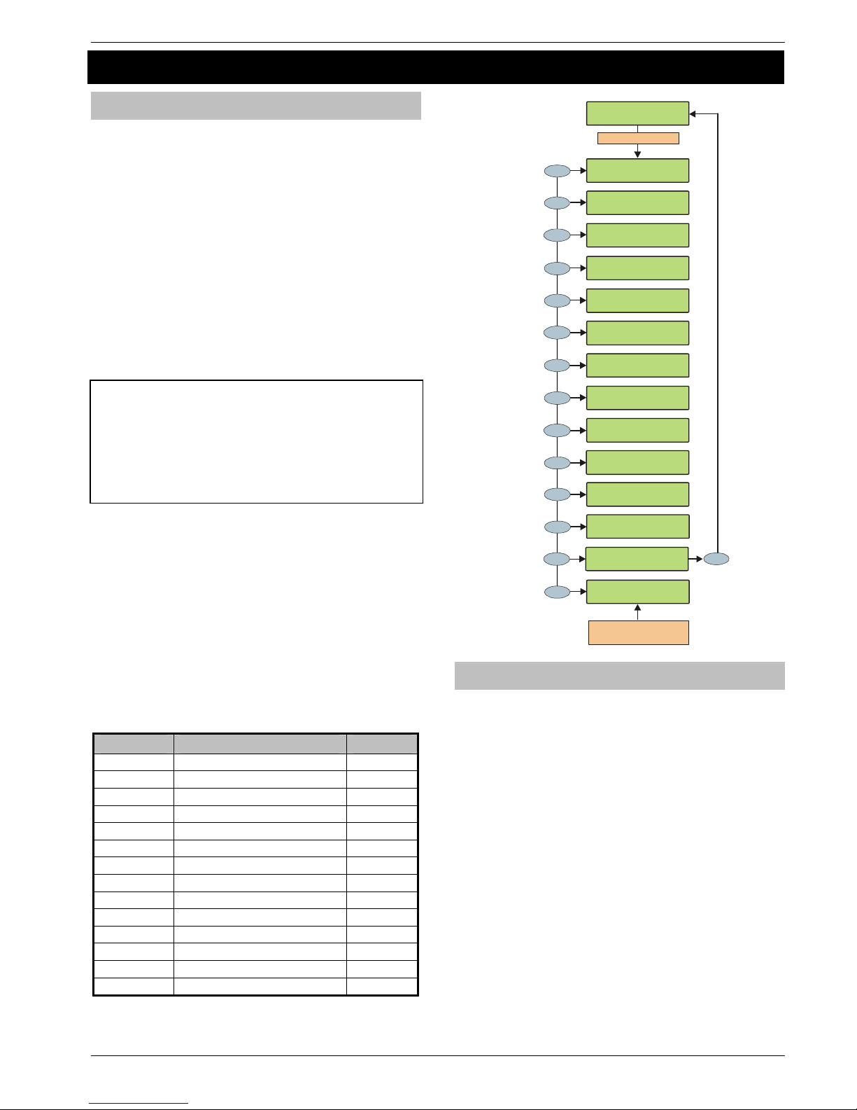
Premier 640 Installation Manual The Programming Menu
INS344 31
5 Programming the Control Panel
Introduction
All engineers should read this section carefully so as to
familiarise themselves with the programming of the control
panel.
Before attempting to program the panel, it is recommended
that the User Profiles and Area Profiles are carefully
defined.
It is strongly recommended that the Premier 640 is
programmed via a PC or Laptop using Wintex UDL software.
When using Wintex the programming menus are intuitive, so
the manual describes programming through the remote
keypad.
To access the Programming menu, enter the factory default
Engineer code
!"#$
.
If a mistake is made whilst entering the Engineer code, simply
re-enter the correct code.
WARNING
When an Engineers code is entered to gain
access to the Programming menu, by default
ALL zones and tampers are disabled.
A menu option can then be selected by pressing one of the
keys shown or by using the
%
key to search. Once
selected, press YES to access that option.
To leave the selected menu option and return to the main
programming menu, press
-
.
To exit from the Main Programming menu but still remain
‘Logged’ onto the system (zones and tampers still disabled),
press
-
and the display will show ‘Alarm Engineer
Working On Site’.
To log the Engineer off the system, press
&
followed by
YES and the system will revert to its normal condition.
The table below shows the menu options available:
Key Menu Option Page
!+
Zone Setup 34
"+
Area Programming 39
#+
Global Options 47
$+
Keypad Setup 56
'+
Expander Setup 58
(+
System Outputs 60
)+
UDL/Digi Options 67
*+
Setup Users 84
.+
Engineer Utils 91
/+
Alter Part Arms 100
,+
The Arming Menu -
,+
The User Menu -
&+
Log Off Engineer 33
-+
Exit programming mode 33
Enter Engineers Code
!!I)$/5$)!X+&X
3(:!%+!Y(8!*%%%
>73!:0!3$-$6:Z[
3$:#O!\<$)<
8
tuv
>73!:0!3$-$6:Z[
\C?]C595!HO:5
08<
7
pqrs
>73!:0!3$-$6:Z[
3=<:$/!H#:O#:<
6
mno
>73!:0!3$-$6:Z[
7PO(8D$)!3$:#O
5
jkl
>73!:0!3$-$6:Z[
Q$=O(D!3$:#O
4
ghi
1
>73!:0!3$-$6:Z[
^08$!3$:#O
2
abc
>73!:0!3$-$6:Z[
.
)$(!I)09)(//58
9
>73!:0!3$-$6:Z[
V-0E(-!HO:508<
3
def
>73!:0!3$-$6:Z[
78958$$)!\:5-<
9
wxyz
>73!:0!3$-$6:Z[
?09!0BB!7LV_L77;
0
_
Menu
C0!=0#!J(8:
.)/589!'$8#!`
Menu
C0!=0#!J(8:
\<$)!'$8#!`
Reset
!.-()/!78958$$)
F0)G589!H8!35:
$1
Yes
Out of P rogramming Menu
(Engineer Still Logged On)
Part
C
0!=0#!J(8:!:0
.-:
$)!I():!.)/<
`
Factory Defaults
The factory default programming is defined in the Factory
Defaults and Quick Reference Guide supplied separately
with the control panel.
Page 32
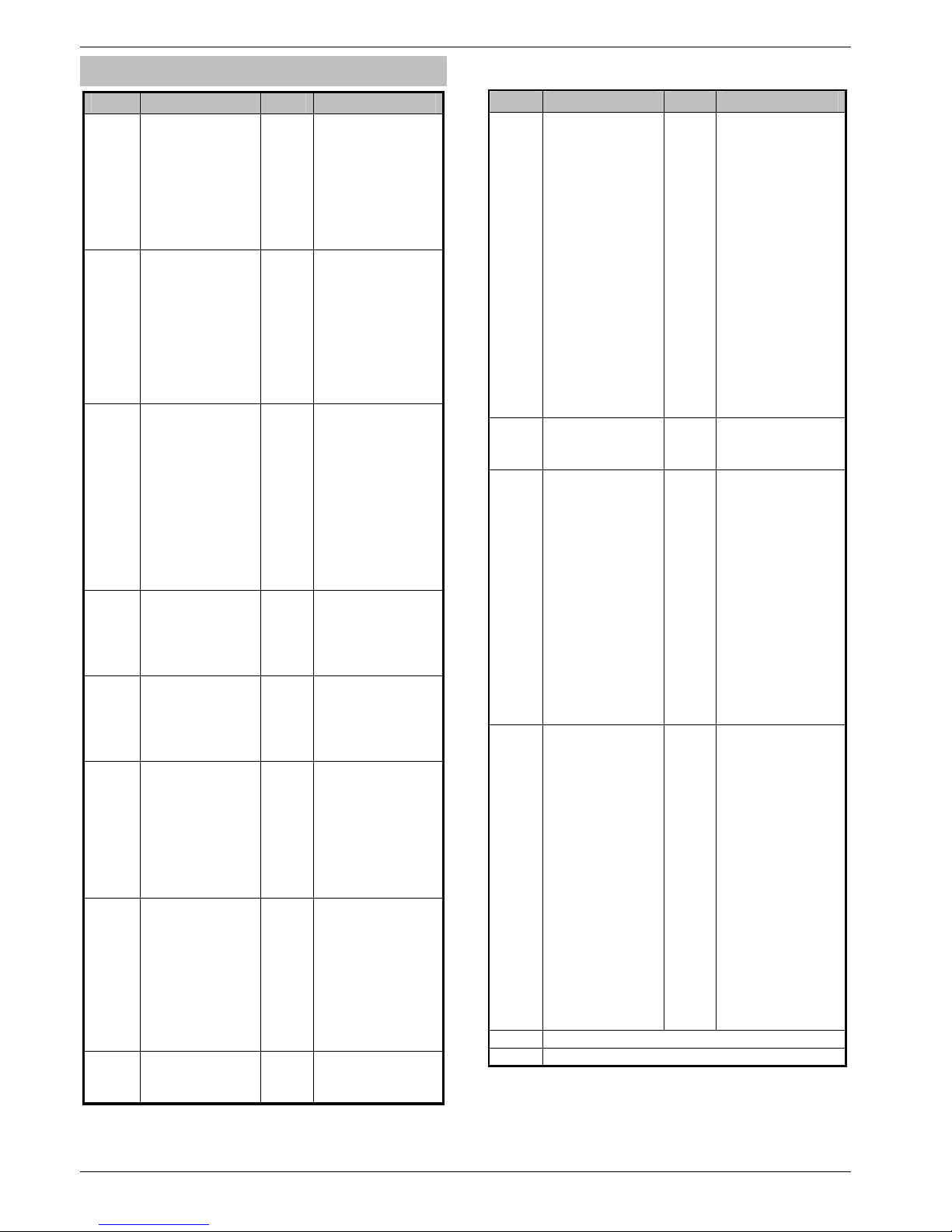
Programming the Control Panel Premier 640 Installation Manual
32 INS344
Programming Menu Guide
Key Main Menu Key Sub Menu
!+
Zone Setup
0
Zone Types
+
0
Zone Attributes 1
+
0
Zone Attributes 2
+
0
Zone Areas
+
0
Zone Text
+
0
Zone Chime
+
0
Zone Test
+
0
Zone Wiring
"+
Area Programming
&
Timers
+
!
Arming Modes
+
"
Area Arm Suites
+
#
Suite ArmText
+
$
Suite Arm Modes
+
'
Area Options
+
(
Time Arm Areas
+
)
Area Text
+
*
Area Profiles
#+
Global Options
&
System Timers
+
!
System Config.
+
"
System Options
+
#
Monitor Hardware
+
$
Control Timers
+
'
System Text
+
(
Part Arm Text
+
)
Holiday Dates
+
*
Speaker Tones
+
.
PC Output Text
+
%
Custom O/P Text
$+
Keypad Setup
0
Areas
+
0
Zone Mapping
+
0
Options
+
0
Speaker Volume
+
0
Sounder Options
'+
Expander Setup
0
Areas
+
0
Location Text
+
0
Auxiliary Input
+
0
Speaker Volume
+
0
Sounder Options
(+
System Outputs
&
Panel Outputs
+
!
Digi Outputs
+
"
Com? Channels
+
#
RedCARE Pins
+
$
Keypad Outputs
+
'
Expander Outputs
+
(
Custom Outputs
+
)
X-10 Outputs
)+
UDL/Digi Options
&
Reset Digi
+
!
Start Test Call
+
"
MSN Pre-Dial No
+
#
Program Digi
+
$
Digi Options
+
'
UDL Options
+
(
Area Accounts
+
)
Setup Modules
+
*
Com Port Setup
*+
Setup Users
&
Add/Edit Users
+
!
User Profiles
+
"
Access Profiles
Key Main Menu Key Sub Menu
.
Engineer Utils
&
View Event Log
+
!
Do Bell Test
+
"
Do Walk Test
+
##
View Zone Status
+
$
System Tests
+
'
Confirm Devices
+
(
View RKP Status
+
)
View Exp. Status
+
*
Set System Time
+
.
Set System Date
+
%#
Location Text
+
%#
Print Log Data
+
%#
Soak Test Areas
+
%#
Change Eng. Code
+
%#
Adjust Volumes
+
%#
Default NVM Data
+
%#
View iD Data
+
%#
Configure Radio
/
Part Arms
1#
Part Arm 1#
#
2#
Part Arm 2#
#
/#
Part Arm 3#
,
Arming Menu
&
Exit Menu#
+
!
Arm System#
+
"
Part Arm System
+
##
Silent Arming#
+
$#
Omit Zones#
+
'
Cancel Exit#
+
(
Disarm Areas#
+
)
Use Anti-code#
+
*
View Zone Status
+
.
Omit 24Hr Zones
+
%#
Set Chime Areas
+
%#
View Act. Faults#
+
%#
View Act. Counts
+
%#
Send SMS Text#
+
%#
Defer Arming#
,
User Menu
&
Exit Menu#
+
!
View Event Log#
+
"
Change Code#
+
#
Edit Chime Zones
+
$
System Tests#
+
'
Walk Test#
+
(
Enable Engineer#
+
)
Set System Time
+
*
Set System Date
#
.
Override Timers#
#
%#
Alter Timers#
#
%#
Setup Users#
#
%#
Alter Part Arms#
#
%#
Call Remote PC#
#
%#
Alter Hol. Dates#
#
%#
Adjust Volumes#
#
%#
Print Event Log#
#
%#
Edit Phone No’s#
-
Exit programming menu (engineer still logged on)#
&
Log Off Engineer
Page 33
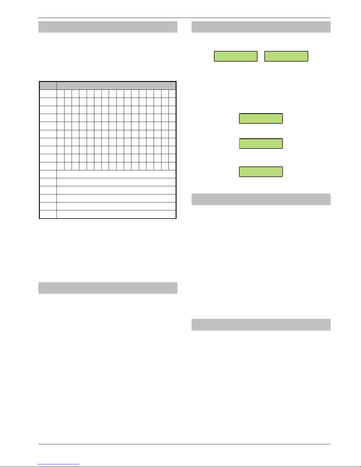
Premier 640 Installation Manual Programming the Control Panel
INS344 33
Programming Text
Text is programmed in a similar way to mobile phones.
Characters are selected by pressing the corresponding key
the appropriate number of times (to select a character on the
same key, press
%
to move the cursor along).
The table below shows the keys to use and the characters
that are assigned to them:
Key Character
&+
_ 0
!+
. , ? ! 1 @ “ - & % / + = $ : ;
"+
A B C 2 a b c
#+
D E F 3 d e f
$+
G H I 4 g h i
'+
J K L 5 j k l
(+
M N O 6 m n o
)+
P Q R S 7 p q r s
*+
T U V 8 t u V
.+
W X Y Z 9 w x y z
%+
Move Cursor
-+
Backspace (delete)
2+
Copy Text
/+
Paste Text
1+
Predictive Text
3+
Upper/Lowercase, Predictive text and Clear Screen
The control panel also features Predictive text. This can be
used to make inserting words easier, i.e. when spelling the
word PIR, instead of typing 7444777, all that you need to do
is type 747 and the word is automatically selected.
!
This feature can be turned on and off as required by
pressing the
1
key and can also be automatically
selected every time text mode is entered (see page 50
for details).
Copying and Pasting
When programming any items i.e. Zones, Timers, Options
etc. pressing CHIME at any point will ‘Copy’ the information
that has just been programmed into memory. To program
another item using the information in memory, select the item
and press PART to ‘Paste’ the information.
!
Copying and Pasting can only be performed whilst in the
same option i.e. if a zone has just been programmed as
Guard 1/Omit/Access/Areas-ABC, ALL of that
information can be copied into memory so that when
another zone is selected, the same information can then
be quickly pasted to the other zone.
The information held in memory after programming an item
can only be pasted into an item of the same type and cannot
be used once another option is selected i.e. Zone
programming information cannot be pasted into Timers etc.
Log Off Engineer
Whenever the Engineer Programming menu is exited by
pressing
-
twice, the display will look like this:
!.-()/!78958$$)
F0)G589!H8!35:$1
!!!!
!"#$!%&!'()!*%%+
This message will remain on the display until the Engineer
logs out of the Programming menu.
4 To log out of Engineer Programming menu, proceed as
follows:
Enter an Engineer code
5555
, the display
should look like this:
>73!:0!3$-$6:Z[
^08$!3$:#O
Press
&
or
-
, the display should look like this:
>73!:0!3$-$6:Z[
?09!0BB!7LV_L77;
Press
0
to return to normal, the display will look
something like this:
!!!!
!"#$!%&!'()!*%%+
The Engineer is now logged out of the Programming menu.
Resetting the Engineers Code (User 00)
If the Engineer code (User 00) has been lost or forgotten, it
can normally be reset back to the factory default of
!"#$
. However, this can only be done if the
NVM has not been locked (see page 49 for details).
To Reset the Engineer code (User 00):
ENSURE THAT THE LID TAMPER IS CLOSED
Hold down the ‘Factory Default’ button for 6 seconds (with
the control panel still powered), after 6 seconds, the
sounders/keypads will bleep to indicate that the Engineer
code has been reset.
!
NO other codes/programming will be affected, it is just
the User 00 Engineer code that will be reset.
The Engineer (User 00) code can only be reset, if the NVM
has not been locked (see page 49 for details).
Other Things to Know
The , key will always return to the previous menu level.
This is often the only way to exit an option after programming
it. Pressing , several times will always return to the top
level menu and the logout screen.
The
6, 1 and - keys often provide shortcuts or
extended functions, refer to individual programming options
for details.
Page 34
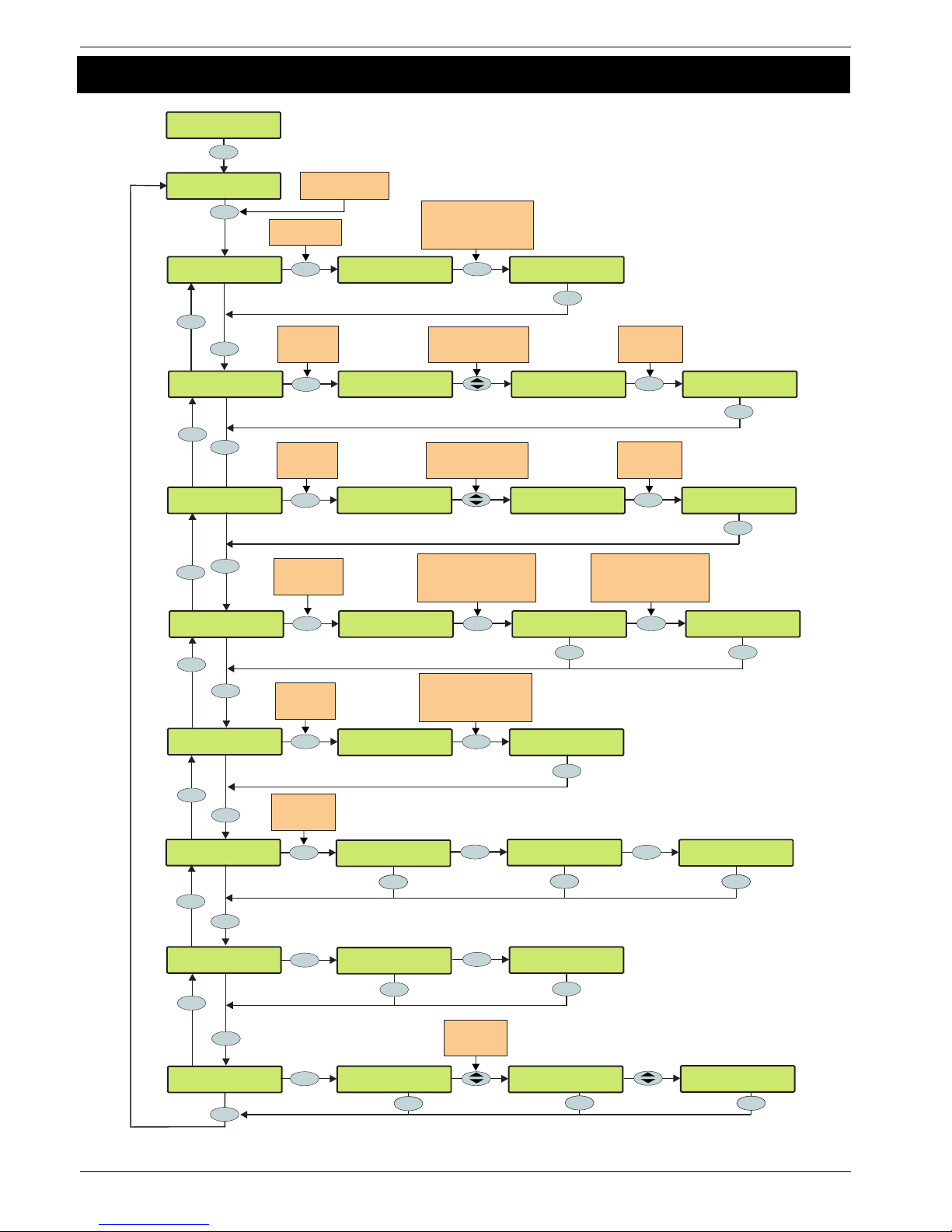
Programming the Control Panel Premier 640 Installation Manual
34 INS344
5.1 Zone Setup
YES to Select:Zone Setup
Zone 004 Attrib1
* * * * * * * *
Zone 004 Area:
* * Area 01 * *
Zone 004 Text:
Zone 004 N1,E1,4
Entry/Exit 1 <
Zone 004 N1,E1,4
Guard <
Use hotkeys 1 - 8 to select
a zone type or use the
SCROLL key to search
e.g. 3 = Guard
Use keys 1 - 8 to select
an attribute or use the
SCROLL key to search
OMITTABLE
>* * * * * * * *
ENTRY/EXIT 2
* * * * * *>* *
Uses Profile 04<
* * Area 04 * *
Enter area profile number
to select area profile
eg 04 = Profile 04
^
Use keys 0 - 9 to program
text the same way that a
mobile phone works
e.g. 7, 444, 777 = PIR
PIR
^
Zone 001 N1,E1,1
Entry/Exit 1
Zone 004 N1,E1,4
Entry/Exit 1
??
Yes
No
3
def
Yes
Yes
No
Yes
No
No
Yes
Yes
No
7
pqrs
Yes
Press NO to
change the zone
area profile
Press NO to
edit the
zone text
Press NO to
edit the zone
attributes 1
Enter zone number
e.g. 004 = Zone 004
???
Press NO to edit
the zone type
Uses Profile 01<
* * Area 01 * *
ENTRY/EXIT 2
* * * * * *>E *
Zone 004 Chime:
Silent
No
Yes
Press NO
to Change the
Chime type
Zone 004 Chime:
Chime 1
Yes
Zone 004 Attrib2
* * * * * * * *
Use keys 1 - 8 to select
an attribute or use the
SCROLL key to search
DOUBLE KNOCK
>* * * * * * * *
AUTO RE-ARM
* * * * *>* * *
Yes
No
Yes
No
Press NO to
edit the zone
attributes 2
AUTO RE-ARM
* * * * *>A * *
Press NO to
select/deselect
the attribute
Press NO to
select/deselect
the attribute
Reset
Reset
Reset
Reset
^
Yes
Zone 004 Test:
RemoteTest Off
No
Yes
Yes
Use scroll keys
to select
wiring type
Zone 004 Test:
RemoteTest On
Yes
Reset
Yes
Reset
No
Yes
Zone 004 Test:
RemoteTest Off
No
Yes
Zone 004 Chime:
Chime 2
^
Yes
No
Yes
Zone 004 Chime:
Chime 3
^
Yes
* * Area 04 * *
04: >A:...4....
Area
Yes
Use Area key to interrogate
area profile.
Then use to scroll
through included areas
U
Zone 004 Wiring:
Double Pole/EOL
Yes
Reset
No
Zone 004 Wiring:
Double Pole/EOL<
Zone 004 Wiring:
1K/1K/(3K) <
Zone 004 Wiring:
4K7/6K8/(12K) <
Yes
Yes
Yes
Yes
Yes
Yes
Page 35

Premier 640 Installation Manual Programming the Control Panel
INS344 35
Zone Types
Each zone must be programmed before it is recognised by
the system.
Zone numbers are entered as a three digit number i.e. Zone 1
would be entered as 001. Each zone consists of a zone type,
attributes, areas and zone text.
When programming zones, first select a zone type then select
any required attributes, assign the zone to an area and then
program any required zone text.
Zone Type + Zone Attributes + Zone Areas + Zone Text =
Zone Programmed.
The following zone types are available:
0 - Not used
A zone that is not monitored by the system, unused zones
should be programmed as ‘Not Used’ or linked out.
1 - Entry/Exit 1
Normally used for the main entry/exit door i.e. Front Door. The
zone can be activated during the exit mode without causing a
‘Fault’. Once the system/area is armed, activation of the zone
will start the ‘Entry 1 Delay’ timer for the selected area.
2 - Entry/Exit 2
Normally used for another entry/exit door that requires a
different entry delay i.e. Back Door, Garage Door etc. The
zone can be activated during the exit mode without causing a
‘Fault’. Once the system/area is armed, activation of the zone
will start the ‘Entry 2 Delay’ timer for the selected area.
!
If any Entry/Exit zone remains active at the end of the entry time, it will
automatically be omitted until the system has been unset and re-set.
If an Entry/Exit zone type is locked out, ‘Guard Access’ zones in the
same area as the omitted Entry/Exit zone will automatically become
‘Entry/Exit 1’ zones to allow access into the premises without causing
an alarm.
If an ‘Entry/Exit 1 or 2’ zone type is assigned the ‘Entry/Exit 2’ attribute (see
page 36), when a zone with the ‘Guard’ attribute activates and causes an
alarm (when the area is fully armed), the zone will become a ‘Guard’ zone
for the duration of the ‘Abort’ timer.
3 - Guard
Normally used for detection devices such as PIR’s, Door
Contacts etc. This zone type will cause an Intruder alarm if it is
activated when the system/area is armed. This zone type will
also activate any output programmed as ‘Guard Alarm’.
4 - Guard Access
Normally used for detection devices along the entry/exit route.
This zone type will allow the user to walk past the detector
without causing a ‘Fault’ during the exit mode or an Intruder
alarm during the entry mode, however, the zone will cause an
immediate Intruder alarm if activated at any other time. This
zone type will also start the entry mode when the system/area
is part armed and activate any output programmed as ‘Guard
Access Alarm’.
5 - 24Hr Audible
This zone type will cause an internal alarm if it is activated
when the system/area is disarmed and will cause an Intruder
alarm when the system/area is armed. The panel will also
report a ‘24-Hour’ alarm to the Alarm Receiving Centre when
using ‘Contact ID’ reporting.
6 - 24Hr Silent
This zone type will cause a silent alarm if it is activated when
the system/area is disarmed and will cause an Intruder alarm
when the system/area is armed. The panel will also report a
‘24-Hour’ Alarm to the Alarm Receiving Centre when using
‘Contact ID’ reporting.
7 - PA Audible
Normally used for monitoring Panic or hold-up alarms. This
zone type will cause a Panic alarm if it is activated when the
system/area is armed or disarmed.
8 - PA Silent
Normally used for monitoring Panic or hold-up alarms. This
zone type will cause a silent Panic alarm if it is activated when
the system/area is armed or disarmed.
9 - Fire
Normally used for monitoring smoke detectors. This zone
type will cause a Fire alarm with distinctive fire tone if it is
activated when the system/area is armed or disarmed. In
addition, the bell output will pulse.
10 - Medical
This zone type will cause a Silent alarm if it is activated when
the system/area is armed or disarmed. The panel will also
report a Medical alarm to the Alarm Receiving Centre when
using ‘Contact ID’ reporting.
11 - 24Hr Gas
This zone type will cause an Audible alarm if it is activated
when the system/area is armed or disarmed. The panel will
also report a 24-Hour Gas alarm to the Alarm Receiving
Centre when using ‘Contact ID’ reporting.
12 - Auxiliary
This zone type will cause a Silent alarm if it is activated when
the system/area is armed or disarmed. The panel will also
report an Auxiliary alarm to the Alarm Receiving Centre when
using ‘Contact ID’ reporting.
13 - Tamper
This zone type will cause an Internal alarm if it is activated
when the system/area is disarmed and will cause an Intruder
alarm when the system/area is armed.
14 - Exit Terminator
This zone type is used to finalise the arming procedure when
arming the system/area (see page 40 for details).
15 - Moment Key
This zone type can be used to arm and disarm one or more
areas. When the zone is activated and then secured the areas
assigned to the zone will arm. When the zone is subsequently
activated and then secured the system will disarm the areas
assigned to the zone. Tamper faults will not arm or disarm
anything, but will cause a Tamper alarm.
16 - Latch Key
This zone type can be used to arm and disarm one or more
areas. When the zone is activated, the areas assigned to the
zone will arm. When the zone is secured, areas assigned to
the zone will disarm. Tamper faults will not arm or disarm
anything, but will cause a Tamper alarm.
17 - Security
This zone type can be used to Lockout keypads. When the
zone is activated, keypads assigned to the same area will not
accept any key presses. When the zone is secured, all
keypads respond as normal.
18 - Omit Key
This zone type will isolate any zone assigned to the same
area as long as it has the ‘Omit’ attribute.
19 - Custom
This zone type can be programmed to operate as required
using its own set of attributes (see page 37 for details).
Page 36

Programming the Control Panel Premier 640 Installation Manual
36 INS344
Zone Attributes 1
Attributes can be assigned to a zone to alter its operation i.e. a
Guard zone with the ‘Access’ attribute will allow the user to
walk past the detector without causing a ‘Fault’ during the exit
mode or an Intruder alarm during the entry mode.
Select attributes by pressing keys 1 to 8 (a letter on the
display means the attribute is selected, a Dot on the display
means the attribute is not selected).
The following attributes are available:
O - OMITTABLE
Zones with this attribute can be manually omitted.
Zones without this attribute cannot be manually omitted.
F - FORCE OMIT
Zones with this attribute will be omitted if they are not secure
at the end of the exit mode.
Zones without this attribute will cause an ‘Arm Fail’ if they are
not secure at the end of the exit mode.
1 - PART 1 OMIT
Zones with this attribute will be omitted when ‘Part Arm 1’ is
selected.
Zones without this attribute will respond as normal.
2 - PART 2 OMIT
Zones with this attribute will be omitted when ‘Part Arm 2’ is
selected.
Zones without this attribute will respond as normal.
3 - PART 3 OMIT
Zones with this attribute will be omitted when ‘Part Arm 3’ is
selected.
Zones without this attribute will respond as normal.
A - ACCESS
Zones with this attribute will not cause a ‘Fault’ during the exit
mode or an Intruder alarm during the entry mode. However, if
the zone is activated at any other time an Intruder alarm will
occur.
Zones without this attribute will respond as normal.
E - ENTRY/EXIT 2
Zones with this attribute will start the ‘Entry Delay 2’ timer for
the selected area when the area is part armed.
!
‘Entry/Exit 1 or 2’ zones with this attribute will become a
‘Guard’ zone for the duration of the ‘Abort’ timer if a zone
with the ‘Guard’ attribute activates and cause an alarm
(when the area is fully armed).
Zones without this attribute will respond as normal.
G - GUARD
Zones with this attribute will cause an Intruder alarm when the
area is part armed (this would normally be used on ‘Entry/Exit
1 or 2’ zone types).
!
When the area is fully armed, activation of a zone with
this attribute will cause any ‘Entry/Exit 1 or 2’ zone with
the Entry/Exit 2 attribute to become a ‘Guard’ zone for
the duration of the ‘Abort’ timer.
Zones without this attribute will respond as normal.
Zone Attributes 2
Select attributes by pressing keys 1 to 8 (a letter on the
display means the attribute is selected, a Dot on the display
means the attribute is not selected).
The following attributes are available:
D - DOUBLE KNOCK
Zones with this attribute will only cause an alarm if it is
activated twice within the ‘Double Knock’ time window or for
the duration of the time window.
Zones without this attribute will respond as normal.
B - BEAM PAIR
Zones with this attribute will only cause an alarm if two zones
(assigned to the same area) with this attribute are activated
within the ‘Beam Pair’ time window.
Zones without this attribute will respond as normal.
T - ON TEST
Zones with this attribute will not cause an alarm if activated
during the ‘Soak Test Time’ (see page 47 for details).
However, the system will record the event in the log and
indicate to the user that the zone has failed the test. A test
failure will NOT prevent the user from arming and will clear
when an Engineer code is entered.
Zones without this attribute will respond as normal.
A - ACTIVITY
Zones with this attribute will cause an activity fault to be
displayed at the time of arming if they have not been
activated during the ‘Activity Delay’ period. If ‘Config. option
14’ (see page 49 for details) has been set to ‘Activity Fault
Bar’ the system/area cannot be armed until the zone has
been activated (forced walk test).
Zones without this attribute will respond as normal.
R - RESET
Zones with this attribute will not be monitored during the
‘Detector Reset’ period i.e. when the exit mode is started and
power is removed from certain detectors (to reset them) the
‘Fault’ on the zone is ignored.
Zones without this attribute will be monitored as normal.
A - AUTO RE-ARM
Zones with this attribute will only re-arm at the end of the bell
duration providing that the ‘Re-arm’ limit has not been
reached (see page 51 for details). Once this limit has been
reached, the zone will lock out and not cause any further
Intruder alarms.
Zones without this attribute will always re-arm at the end of
the bell duration.
Q - QUICK RESPONSE.
The response time of the zones with this attribute is governed
by the ‘Zone Loop’ response Timer (see page 47 for details).
The response time of a zone without this attribute is fixed at
250mS.
E – ENGINEER ALARM
Zones with this attribute will cause an Intruder alarm when
activated if the engineer arms the system/area.
Zones without this attribute will not cause an Intruder alarm
when activated if the engineer arms the system/area.
Page 37

Premier 640 Installation Manual Programming the Control Panel
INS344 37
Attributes for Moment or Latch Keys
Select attributes by pressing keys 1 to 8 (a letter on the
display means the attribute is selected, a Dot on the display
means the attribute is not selected).
The following attributes are only available for ‘Moment Key’ or
‘Latch Key’ zone types.
I - INSTANT ARM
When using a key switch, the area will arm instantly.
P - PART ARMING
When using a key switch, the area will ‘Part’ arm.
F – FULL ARM DISABLE
When using a key switch to ‘Full’ arm an area, the key switch
is disabled once the area is armed.
D - DISARM ONLY
The key switch cannot be used for ‘Arming’ (it can only be
used for ‘Disarming’).
F - SILENTARMING
When arming using a key switch, the selected areas will arm
silently.
T - TIME ARM DISABLE
Activation of the key switch will override the ‘Time Arming’
feature on the control panel and prevent it from operating
until the zone is reinstated.
K - KEY TUBE
A key switch zone type with this attribute will log when the
zone is activated and also when the zone is restored.
Attributes for Custom Zones
Select attributes by pressing keys 1 to 8 (a letter on the
display means the attribute is selected, a Dot on the display
means the attribute is not selected).
The following attributes are only available for ‘Custom’ zone
types.
I - INTERNAL
Activation of this zone (when armed) will cause the internal
sounders to activate.
B - BELL/STROBE
Activation of this zone (when armed) will cause the external
sounder/strobe to activate.
M - MONITOR 24Hr
The zone is armed at all times.
C - ENABLE COMS
Activation of this zone (when armed) will cause the area
‘Alarm’ output to activate.
!
Any Custom zone with this attribute will activate both
the internal and external sounders even if they are not
enabled above.
W - WARNING REQ.
If the zone remains Active for the duration of the ‘Warning
Delay’ timer (see page 48), a warning tone will occur every 30
seconds for 3 minutes (or until a code is entered or
-
is
pressed).
!
If MONITOR 24Hr is enabled, an internal alarm will
occur after the Warning Delay.
Zone Areas
The Premier 640 provides 80 Area Profiles. Each zone can be
allocated to an Area Profile which will determine which area(s) it
is assigned to.
See page 46 for Area Profile programming.
!
If a zone is assigned to an Area Profile that contains
more than one area, it will only be recognised by the
system when all areas it is assigned to, are armed.
Zone Text
Each zone can have up to 32 characters of descriptive text
assigned to it. Text is programmed in a similar way to mobile
phones. Select characters by pressing the corresponding key
the appropriate number of times (to select a character on the
same key, press
%
to move the cursor along).
For a more information, see page 33.
The control panel also features Predictive text. This can be
used to make inserting words easier, i.e. when spelling the
word PIR, instead of typing 7444777, all that you need to do
is type 747 and the word is automatically selected.
!
This feature can be turned off if required by pressing
the
1
key and can also be automatically selected
every time text mode is entered.
Zone Chime
Each zone can be programmed to chime the internal sounders
using one of the available chime tones when activated.
Remote Test Enable
Any zone with this attribute will be tested when the remote
test function is initiated from Wintex. Any detector on a zone
with the remote test attribute will be expected to go into alarm
during the remote test, if it does not go into alarm, the
detector will be reported as faulty.
!
This facility is only to be used in conjunction with
system output type 47 ‘Detector Test’ see page 63.
Page 38
Programming the Control Panel Premier 640 Installation Manual
38 INS344
Zone Wiring
Zone wiring connections are shown on page 21 the following
programming options are available.
0 - Normally Closed
For use on normally closed devices without tamper
protection. Normally used for keyswitches. See Normaly
Closed wiring diagram on page 21
1 - Normally Open
For use on normally closed devices without tamper
protection. Normally used for keyswitches. See Normaly
Open wiring diagram on page 21
2 - Double Pole/EOL
Default zone wiring configuration as shown on page 21
3 - Triple EOL
Standard Texecom TEOL as illustrated on page 21, use this
wiring type for all Texecom anti masking detectors.
4 - 1K/1K/(3K)
Alternative TEOL configuration with 1K alarm resistor, 3K fault
resistor and 1K EOL resistor
5 - 4K7/6k8/(12K)
Alternative TEOL configuration with 6K8 alarm resistor, 12K
fault resistor and 4K7 EOL resistor.
6 - 2K2/4K7/(6k8)
Alternative TEOL configuration with 4K7 alarm resistor, 6K8
fault resistor and 2K2 EOL resistor
7 - 4K7/4k7
Alternative EOL configuration with 4K7 alarm resistor and 4K7
EOL resistor.
8 - WD Monitor
Specialised wiring configuration for monitoring warning
devices with fault reporting capability. Only use this wiring
type on zones types programmed as Auxilliary. Normally
wired as a Normally Closed circuit.
DD 243
To comply with DD 243, during the normal entry delay, the
control panel must prevent a Confirmed Intruder Alarm from
being reported to the Alarm Receiving Centre.
WARNING
Owing to the ability to disable ALL of the
confirmation facilities, the customer should be
advised in writing by the alarm company that ALL
means of alarm confirmation are disabled when the
initial entry door is opened. The alarm company
should then obtain written acceptance from the
customer of the disabling of the means of alarm
confirmation.
Page 39
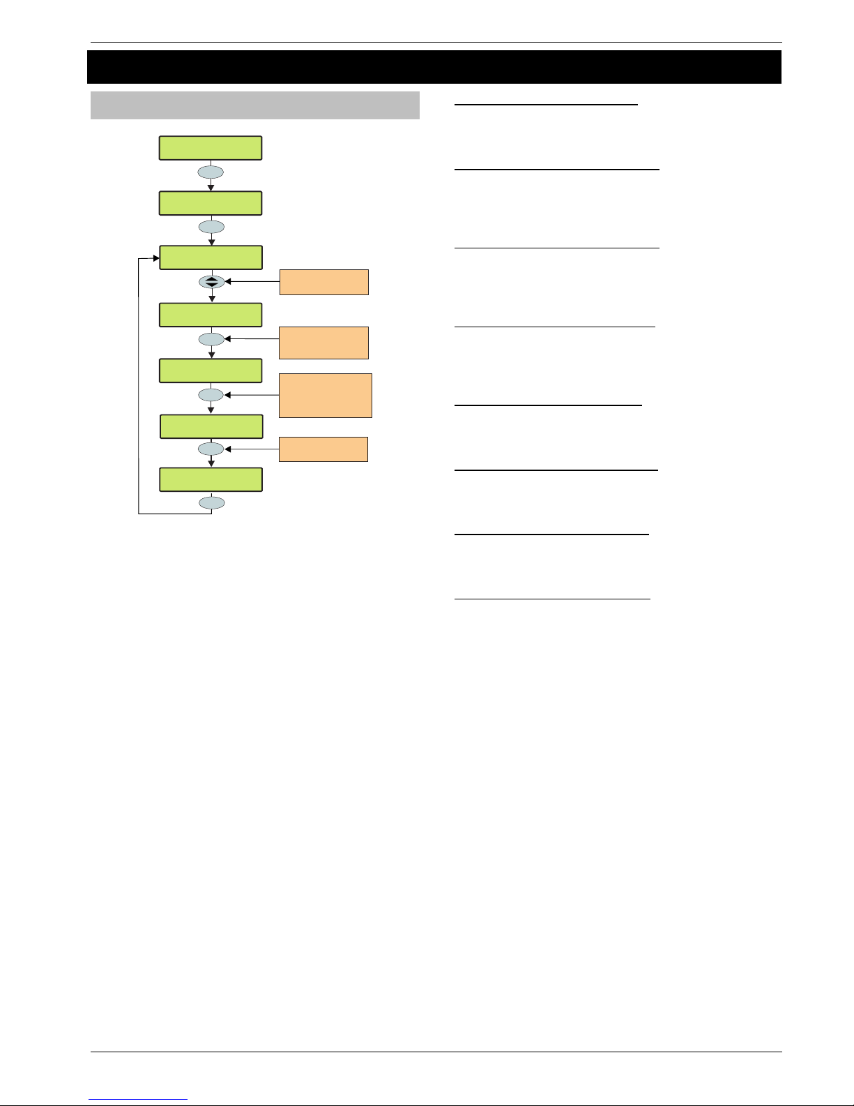
Premier 640 Installation Manual Programming the Control Panel
INS344 39
5.2. Area Programming
Timers
YES to Select:Area Programming
Yes
Yes
Area Programming
Timers
Use the AREA key to
Jump a block of 8 areas
(A2-B2, C1-D1 etc)
Yes
Enter a new timer value
e.g. 025 = 25 Seconds
???
Yes
P
ress YES to move to
the required timer group
or press RESET to move
backwards e.g. YES
A2> Exit Delay
030 Second(s)
B2> Exit Delay
030 Second(s)
B2> Entry 1 Delay
>025 Second(s)
B2> Entry 1 Delay
020 Second(s)
Use the SCROLL key to
select an area
A1> Exit Delay
030 Second(s)
Area
These groups of ‘Area’ timers control timing and delay
functions for areas A1 – H8. Each timer can be programmed
for any value between 000 and 999.
1 - Exit Delay- for Areas A1 to H8
When the area exit mode is programmed as ‘Timed’ this timer
controls the delay between the user initiating the exit mode
for the selected area and the area actually.
2 - Entry 1 Delay - for Areas A1 to H8
If the area is armed and an ‘Entry/Exit 1’ zone is activated,
this timer will start and the entry tone will be heard. If the area
is not disarmed before this timer expires, the ‘2nd Entry Delay’
timer will start.
3 - Entry 2 Delay - for Areas A1 to H8
If the area is armed and an ‘Entry/Exit 2’ zone is activated,
this timer will start and the entry tone will be heard. If the area
is not disarmed before this timer expires, the ‘2nd Entry Delay’
timer will start.
4 - 2
nd
Entry Dly - for Areas A1 to H8
When the area ‘Entry Delay 1 or 2’ timer expires, this timer will
start and an Internal alarm will occur. If the area is still not
disarmed before this timer expires, an Intruder alarm will then
occur.
5 - Bell Delay - for Areas A1 to H8
This timer controls the delay between an Intruder alarm
occurring in the selected area and the ‘Bell/Strobe’ output
activating.
6 - Bell Duration - for Areas A1 to H8
This timer controls the duration of the ‘Bell’ output after an
Intruder alarm has occurred in the selected area and any
programmed ‘Bell Delay’ has expired.
7 - Coms Delay. for Areas A1 to H8
This timer controls the delay between an Intruder alarm
occurring in the selected area and the communicator reporting to
the Alarm Receiving Centre.
8 - Part Bell Dly. for Areas A1 to H8
When the selected area is ‘Part Armed’ this timer controls the
delay between an Intruder alarm occurring in the selected
area and the ‘Bell/Strobe’ output activating, the internal
sounders will also sound during this time as a warning.
Page 40
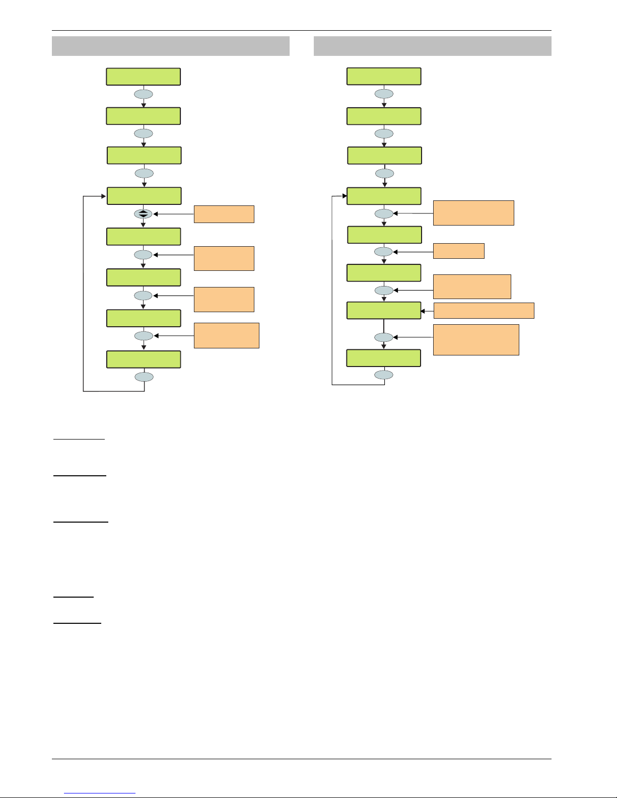
Programming the Control Panel Premier 640 Installation Manual
40 INS344
Arming Modes
YES to Select:Area Programming
Yes
Yes
Area Programming
Arming Modes
Area A1 Arm by:
Timed exit
1
Area B2 Arm by:
Entry/Exit <
Yes
Area A2 Arm by:
Timed exit
Use keys 1 - 5 to select
an arming mode
e.g. 1 = Entry/Exit
1
_
Area Programming
Timers
Use the SCROLL key
to select an area
Area B2 Arm by:
Timed exit
Use the AREA key
to jump 8 areas
(ie A2 - B2)
Area B2 Arm by:
Timed exit <
Press NO to edit the
arming method for the
selected area
Area
No
The way that an area arms can be configured for any of the
following options:
1 - Entry/Exit
The area will arm after the ‘Entry/Exit’ door has been closed
and the ‘Exit Settle’ timer has expired.
2 - Exit Term.
The area will arm after the ‘Entry/Exit’ door has been closed,
the ‘Exit Terminator’ button has been pressed and the ‘Exit
Settle’ timer has expired.
3 - Timed Exit
The area will arm after the programmed ‘Exit Time’ has
expired.
!
If an ‘Exit Terminator’ zone is activated at any point
during the exit mode, any remaining exit time is
cancelled and the area will arm immediately.
4 - Instant
The area will arm instantly.
5 - Deferred
The area will arm after the programmed ‘Exit Time’ has
expired. However, if any zones not on the exit route are
activated during the exit mode, the ‘Exit Time’ is restarted.
Area Arm Suites
YES to Select:Area Programming
Yes
Area Programming
Area Arm Suites
Yes
2
abc
Area Programming
Timers
Area Arm Suite01
* * No Areas * *
No
??
Area Arm Suite04
* * No Areas * *
Uses Profile 00<
* * No Areas * *
Use number keys or scroll to
select an
Area Arm Suite
e.g. 04 selects Arm Suite 04
??
Uses Profile 03<
* * Area 03 * *
Area
Press NO to edit
the Part Arm Suite
Use number keys or scroll to
select an Area Profile
e.g. 03 selects Area Profile 03
Top line
Bottom line
shows the profile number
shows the Area Profile text
Yes
* Area 03 * *
03: >A:..3.....
Use the AREA key to show the
configuration of the selected
Area Profile use to navigate
assigned areas
U
The Premier 640 has 16 Area Arm Suites. Any number of
areas can be assigned to each suite via Area Profiles.
Assigning an Area Profile to an Area Arm Suite will assign all
areas in the Area Profile to the Area Arm Suite. Areas
assigned to an Area Arm Suite will be armed when the suite is
selected, making it easier for the user to select multiple areas
if required.
!
Descriptive text may also be assigned to the Area Arm
Suite (see page 41 for details).
Area Arm Suite Controller
The suites can be assigned to keypads so that different
combinations of areas can be armed or disarmed depending
on which keypad is used (see page 57 for details) and
operates as follows:
• Keypad 1 = Area Arm Suite 1, Keypad 2 = Area Arm
Suite 2, Keypad 3 = Area Arm Suite 3 etc.
• When a User code is entered at a keypad, one of the
‘Area Arm Suites’ is selected (depending on which
keypad was used) and the areas contained within that
suite (via the Area Profile) will arm using the arming
mode for that suite, the keypad sounder will also follow
the areas defined by the suite.
Page 41
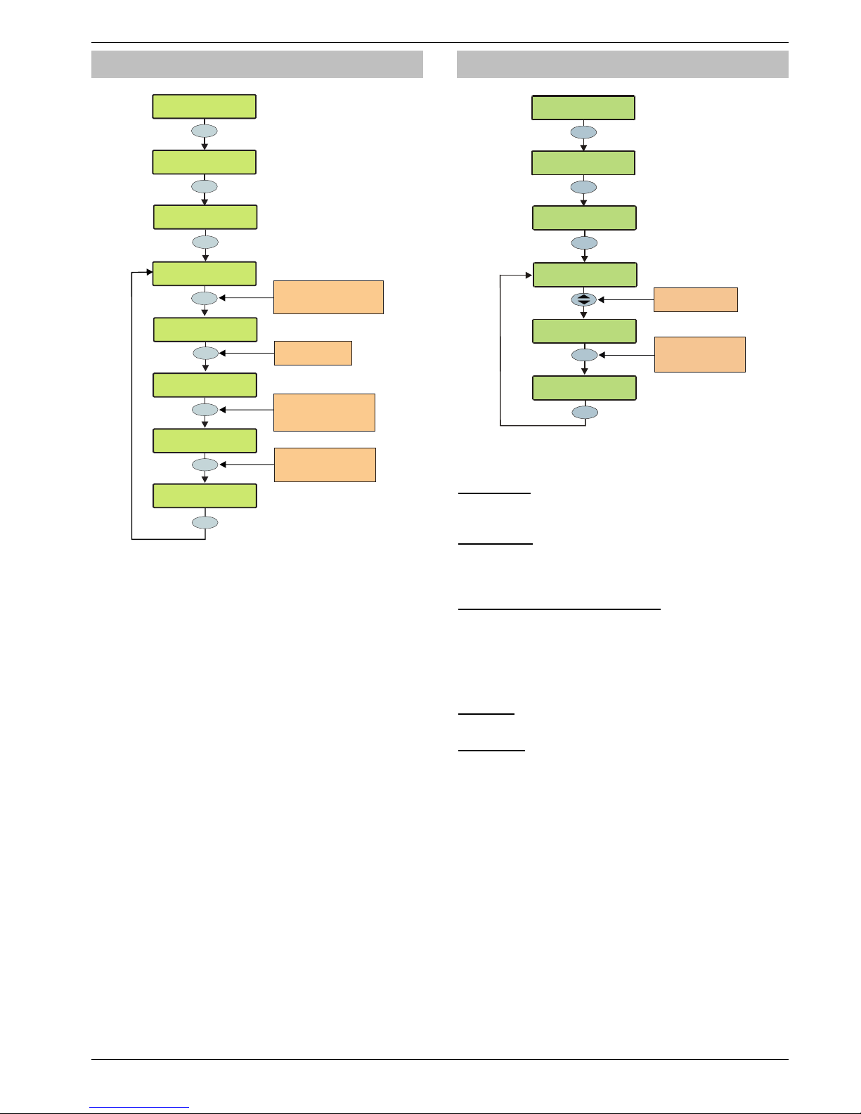
Premier 640 Installation Manual Programming the Control Panel
INS344 41
Area Suite Text
YES to Select:Area Programming
Yes
Area Programming
Area Suite Text
Yes
3
def
Area Programming
Timers
Arm Suite 1Area
No
Omit
^Edit Text >TXT
Use number keys or scroll to
select an
Area Arm Suite
e.g. 04 selects Arm Suite 04
??
Area Arm Suite 4
Yes
^Edit Text >ABC
Use keys 0 - 9 to program
text the same way that a
mobile phone works
Press NO to edit the
Area Arm Suite text
????
Bedtime Setting
Edit Text >A^C
Use Omit key to switch
between predictive text
(TXT) and character (ABC)
Entry
Text may be assigned to the Area Arm Suites to allow the user
to select the suites by description instead of number. Up to 16
characters of text can be programmed for each suite.
Text is programmed in a similar way to mobile phones. Select
characters by pressing the corresponding key the
appropriate number of times (to select a character on the
same key, press
%
to move the cursor along).
Suite Arm Modes
>73!:0!3$-$6:Z[
.)$(!I)09)(//589
Yes
.)$(!I)09)(//589
3#5:$!.)/!'0D$<
Yes
4
ghi
.)$(!I)09)(//589
"5/$)<
Yes
3#5:$!+!.)/!E=Z
!!!"5/$D!$P5:
1
3#5:$!*!.)/!E=Z
!W!78:)=]7P5:
3#5:$!*!.)/!E=Z
!!!"5/$D!$P5:
Use keys 1 - 5 to select
an arming mode
e.g. 1 = Entry/Exit
Use the SCROLL key
to select a suite
The way that an Area Arm Suite arms when selected, can be
configured for any of the following options:
1 - Entry/Exit
The suite will arm after the ‘Entry/Exit’ door has been closed
and the ‘Exit Settle’ timer has expired.
2 - Exit Term.
The suite will arm after the ‘Entry/Exit’ door has been closed,
the ‘Exit Terminator’ button has been pressed and the ‘Exit
Settle’ timer has expired.
3 - Timed Exit (Default for All Areas)
The suite will arm after the programmed ‘Exit Time’ has
expired.
!
If an ‘Exit Terminator’ zone is activated at any point
during the exit mode, any remaining exit time is
cancelled and the area will arm immediately.
4 - Instant
The suite will arm instantly.
5 - Deferred
The suite will arm after the programmed ‘Exit Time’ has
expired. However, if any zones not on the exit route are
activated during the exit mode, the ‘Exit Time’ is restarted.
Page 42
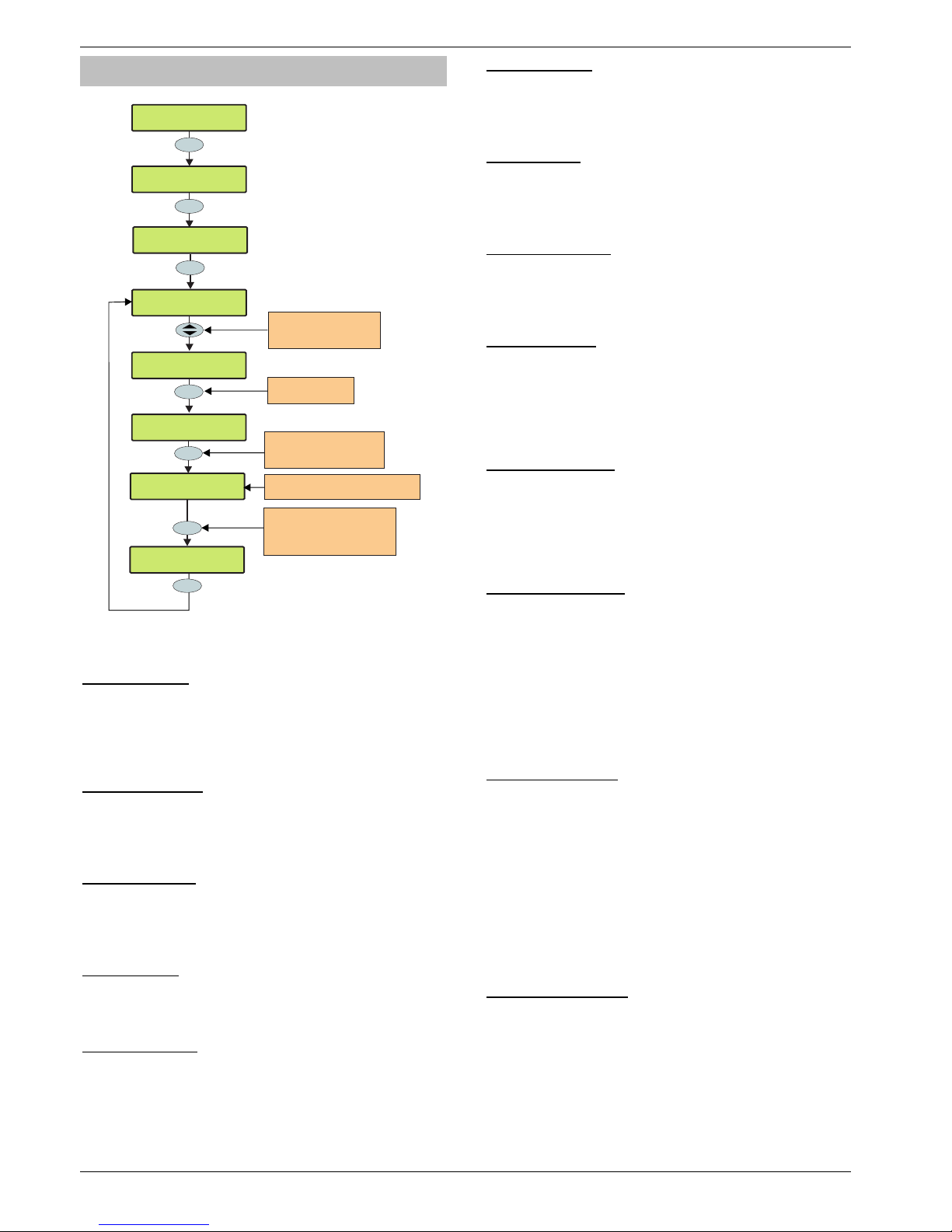
Programming the Control Panel Premier 640 Installation Manual
42 INS344
Area Options
YES to Select:Area Programming
Yes
Area Programming
Area Options
Yes
5
jkl
Area Programming
Timers
Auto Part Arm
No Areas
??
No
Use the SCROLL key
to select an area option
or enter the option number
Remote Arm
No Areas
Press NO to change
the area option
Uses Profile 00<
* * No Areas * *
Use number keys or scroll to
select an Area Profile
e.g. 03 selects Area Profile 03
Uses Profile 03<
* * Area 03 * *
Area
Top line shows
Bottom line shows
the profile number
the Area Profile text
Yes
* * Area 03 * *
03: >A:..3.....
Use the AREA key to show the
configuration of the selected
Area Profile use to navigate
assigned areas
U
These options control how various features affect each area.
Areas are assigned via Area Profiles.
1 - Auto Part Arm
Areas assigned to ‘Auto Part Arm’ will fully arm if an
‘Entry/Exit’ zone is activated during the exit mode and will
‘Part Arm 1’ if an ‘Entry/Exit’ zone is not activated during the
exit mode.
Areas not assigned to ‘Auto Part’ will always fully arm.
2 - Part Arm Instant
Areas assigned to ‘Part Arm Instant’ will arm instantly when
part arming.
Areas not assigned to ‘Part Arm Instant’ will use the area exit
timer when part arming.
3 - Part Arm Silent
Areas assigned to ‘Part Arm Silent’ will never generate Exit
tones when part arming.
Areas not assigned to ‘Part Arm Silent’ will always generate
Exit tones when part arming.
4 - Remote Arm
Areas assigned to ‘Remote Arm’ can be armed remotely
using the Wintex UDL software and a PC.
Areas not assigned cannot be armed remotely.
5 - Remote Disarm
Areas assigned to ‘Remote Disarm’ can be disarmed
remotely using the Wintex UDL software and a PC.
Areas not assigned to ‘Remote Arming’ cannot be disarmed
remotely.
6 - Panel Tamper
Areas assigned to ‘Panel Tamper’ will cause a Tamper alarm
when the control panel cover is removed.
Areas not assigned to ‘Panel Tamper’ will never cause a
Tamper alarm when the control panel cover is removed.
7 - Bell Tamper
Areas assigned to ‘Bell Tamper’ will cause a Tamper alarm
when the Bell tamper loop is broken.
Areas not assigned to ‘Bell Tamper’ will never cause a
Tamper alarm when the bell tamper loop is broken.
8 - Auxiliary Tamper
Areas assigned to ‘Auxiliary Tamper’ will cause a Tamper
alarm when the Auxiliary tamper loop is broken.
Areas not assigned to ‘Auxiliary Tamper’ will never cause a
Tamper alarm when the auxiliary tamper loop is broken.
9 - Panel Speaker
Areas assigned to ‘Panel Speaker’ will cause the control
panel speaker to activate when those areas are in alarm,
entry and exit etc.
Areas not assigned to ‘Panel Speaker’ will never cause the
control panel speaker to activate when those areas are in
alarm, entry and exit etc.
10 - Bell & Strobe op
Areas assigned to ‘Bell & Strobe op’ will cause the
‘Bell/Strobe’ output on the control panel to activate when an
alarm occurs in those areas.
Areas not assigned to ‘Bell & Strobe op’ will never cause the
‘Bell/Strobe’ output on the control panel to activate when an
alarm occurs in those areas.
11 - Alarms Eng Reset
Each area can be programmed for Engineer or User reset
following an Intruder alarm. Areas Assigned to ‘Alarms Eng
Reset’ will respond as follows:
• The assigned areas can only be reset using an Engineer
code
If ‘Anti-code Reset’ is enabled (option 14) the assigned
areas can also be reset using the Anti-code
Areas not assigned to ‘Alarms Eng Reset’ can be reset with
any User code that is valid for those areas.
12 - Confirmed Reset
Each area can be programmed for Engineer or User reset
following a Confirmed alarm. Areas Assigned to ‘Confirmed
Reset’ will respond as follows:
• The assigned areas can only be reset using an Engineer
code
If ‘Anti-code Reset’ is enabled (option 14) the assigned
areas can also be reset using the Anti-code
Areas not assigned to ‘Confirmed Reset’ can only be reset
with any User code that is valid for those areas providing that
‘Alarms Eng Reset’ (option 14) is also programmed for user
reset.
13 - Tamper Eng Reset
Each area can be programmed for Engineer or User reset
following a Tamper alarm (when the area is unarmed). Areas
assigned to ‘Tamper Eng Reset’ will respond as follows:
• The assigned areas can only be reset using an Engineer
code
• If ‘Anti-code Reset’ is enabled (option 14) the assigned
areas can also be reset using the Anti-code
Areas not assigned to ‘Tamper Eng Reset’ can be reset with
any User code that is valid for those areas.
Page 43

Premier 640 Installation Manual Programming the Control Panel
INS344 43
14 - Anti-code Reset
Each area can be programmed for Anti-code Reset following
an Intruder or Tamper alarm. Areas assigned to ‘Anti-code
Reset’ will respond as follows:
• The assigned areas can be reset using the Anti-code as
well as an Engineer code
Areas not assigned to ‘Anti-code Reset’ can only be reset
using an Engineer code or User code.
!
Areas can only be assigned to ‘Anti-code Reset’ if they
are also assigned to ‘Alarms Eng Reset’.
15 - ATS Path Faults
Areas assigned to ‘ATS Path Faults’ (ATS = Alarm
Transmission System) will respond as follows when an ATS
fault occurs.
• All keypads will display ‘ATS Path Fault’
• All keypads and speakers assigned to the same area as
the ‘ATS Path Fault’ will generate a Service tone every 30
Seconds until the fault is acknowledged by the User
entering a valid code for that area
• An assigned area can be armed, as long as ‘Arm With No
ATS’ is also assigned to that area (see option 16). However,
a warning will be given to indicate the problem
Areas not assigned to ‘ATS Path Faults’ will never be affected
by an ATS fault.
16 - Arm With No ATS
Areas assigned to ‘Arm With No ATS’ (ATS = Alarm
Transmission System) can be armed when an ATS fault
occurs in those areas (see option 15).
Areas not assigned to ‘Arm With No ATS’ can never be armed
when an ATS fault occurs in those areas (see option 15).
17 - AC Mains Fail
Areas assigned to ‘AC Mains Fail’ will respond as follows
when an AC mains failure occurs.
• All keypads will display ‘AC Mains Fail’
• All keypads and speakers assigned to the same area as
the ‘AC Mains Fail’ will generate a Service tone every
minute until the fault is acknowledged by the User
entering a valid code for that area
• An assigned area can be armed, as long as ‘Arm With AC
Fail’ is also assigned to that area (see option 18). However,
a warning will be given to indicate the problem
Areas not assigned to ‘AC Mains Fail’ will never be affected
by an AC mains failure.
18 - Arm with AC Fail
Areas assigned to ‘Arm With AC Fail’ can be armed when an AC
Mains fail occurs in those areas (see option 17).
Areas not assigned to ‘Arm With AC Fail’ can never be armed
when an AC Mains fail occurs in those areas (see option 17).
19 - Full Arm Coms
Areas assigned to ‘Full Arm Coms’ will respond as follows:
• If the selected area is fully armed and an Intruder alarm
occurs in that area, Intruder alarm events (for that area) are
reported to the Alarm Receiving Centre after any
programmed ‘Digi delay’ has expired
Areas not assigned to ‘Full Arm Coms’ will never report Intruder
alarm events to the Alarm Receiving Centre when they are fully
armed.
20 - Part Arm Coms
Areas assigned to ‘Part Arm Coms’ will respond as follows:
• If an assigned area is part armed and an Intruder alarm
occurs in that area, Intruder alarm events (for that area) are
reported to the Alarm Receiving Centre after any
programmed ‘Digi delay’ has expired
Areas not assigned to ‘Part Arm Coms’ will never report
Intruder alarm events to the Alarm Receiving Centre when the
area is Part armed.
21 - Unarm Fire Coms
Areas assigned to ‘Unarm Fire Coms’ will respond as follows:
• If an assigned area is unarmed and a Fire alarm occurs in
that area, Fire alarm events (for that area) will be reported
to the Alarm Receiving Centre
Areas not assigned to ‘Unarm Fire Coms’ will never report
Fire alarm events to the Alarm Receiving Centre when the
area is unarmed.
!
Fire alarm events are always reported to the Alarm
Receiving Centre when the area is armed regardless of
whether the area is assigned to this option or not.
22 - Unarm Tamp. Coms
Areas assigned to ‘Unarm Tamp. Coms’ will respond as follows:
• If an assigned area is unarmed and a 24Hr or Tamper
alarm or reportable fault occurs in that area, the event will
be reported to the Alarm Receiving Centre
Areas not assigned to ‘Unarm Tamp. Coms’ will never report
24Hr or Tamper alarm events or faults to the Alarm Receiving
Centre when the area is unarmed.
!
24Hr and Tamper alarm events are always reported to
the Alarm Receiving Centre when the area is armed
regardless of whether the area is assigned to this
option or not.
23 - Auto Arm Areas
Areas assigned to ‘Auto Arm Areas’ will respond as follows:
• When an assigned area is disarmed, the ‘Auto Arm
Delay’ timer will start (see page 47 for details)
• Every time a detector in that area is activated, the timer is
restarted
• If the timer is allowed to expire i.e. no detectors in the
assigned area are activated, the area will arm itself
Areas not assigned to ‘Auto Arm Areas’ will never try to arm
themselves.
24 - Area A Foyer
Area A1 can be used as a common area (automatically arms
last and disarms first). Areas assigned to ‘Area A Foyer’ will
cause the panel to respond as follows:
• When all assigned areas are armed, Area A1 will
automatically arm itself
• When any one assigned area is disarmed, Area A1 will
automatically disarm itself
Areas not assigned to ‘Area A Foyer’ will not affect the
automatic arming of area A1.
Page 44

Programming the Control Panel Premier 640 Installation Manual
44 INS344
25 - Log Part Omits
Areas assigned to ‘Log Part Omits’ respond as follows:
• When an assigned area is part armed, all the zones that
are omitted for that area are logged in the event log
Areas not assigned to ‘Log Part Omit’ will never log the zones
that are omitted in the event log when the area is part armed.
26 - Multi Knock Area
Areas assigned to ‘Multi Knock Area’ will respond as follows:
• Zones with the ‘Double Knock’ attribute will use the
multiple knock value set up in system options for zone
activations (see page 51 for details)
Areas not assigned to ‘Multi Knock Area’ will use the standard
2 knocks for zone activations.
For the ‘Multi Knock Area’ feature to work, the zone must be
programmed with the ‘Double Knock’ attribute (see page 36
for details).
27 - UDL Keypad
Areas assigned to ‘UDL Keypad’ can be controlled i.e. armed,
disarmed, reset etc. from the ‘On Line Keypad’ when using
the Wintex software and a PC.
Areas not assigned to ‘UDL Keypad’ cannot be controlled i.e.
armed, disarmed, reset etc. from the ‘On Line Keypad’ when
using the Wintex software and a PC.
28 - Auto Chime (C2A)
Areas assigned to ‘Auto Chime’ will respond as follows:
• Zones assigned to the selected areas that have been
programmed for ‘Chime’ will only chime when ‘Custom
Output 1, Stage A’ is on
Areas not assigned to ‘Auto Chime’ will only chime when
chime for that area is manually enabled by the user.
DD 243 Options
To comply with DD 243, during the normal entry delay, the
control panel must prevent a Confirmed Intruder Alarm from
being reported to the Alarm Receiving Centre.
If a Portable ACE i.e. Electronic Keyswitch, Key Fob, Tag, Swipe
Card etc is being used for disarming, it is permissible for the
Confirmed Intruder Alarm signal to be re-enabled after the entry
delay has expired.
The following two options have been provided to ensure that
the control panel can be programmed to comply with this
standard if required.
WARNING
Owing to the ability to disable ALL of the
confirmation facilities, the customer should be
advised in writing by the alarm company that ALL
means of alarm confirmation are disabled when the
initial entry door is opened. The alarm company
should then obtain written acceptance from the
customer of the disabling of the means of alarm
confirmation.
29 - Confirm in Entry
Areas assigned to ‘Confirm in Entry’ will respond as follows:
• If the entry mode is started for the selected area and a
Confirmed Intruder alarm occurs in that area, Confirmed
Intruder alarm events (for that area) are reported to the
Alarm Receiving Centre
Areas not assigned to ‘Confirm in Entry’ will never report
Confirmed Intruder alarm events to the Alarm Receiving
Centre during the entry mode.
!
To comply with DD 243, areas must NOT be assigned
to this option, thus preventing Confirmed Intruder
Alarms from being reported to the Alarm Receiving
Centre during the entry mode.
30 - Conf. after Entry
Areas assigned to ‘Conf. After Entry’ will respond as follows:
• Alarm confirmation is ONLY disabled for the duration of the
Entry Time and is RE-ENABLED once the Entry Time has
expired, after which activation of a further two zones that are
not on the entry route must occur before the Alarm
Confirmation output will activate
Areas not assigned to ‘Conf. After Entry’ will never report
Confirmed Intruder alarm events to the Alarm Receiving
Centre after the entry delay has expired.
!
To comply with DD 243, areas must NOT be assigned
to this option, thus preventing Confirmed Intruder
Alarms from being reported to the Alarm Receiving
Centre after the entry delay has expired.
If a Portable ACE i.e. Electronic Keyswitch, Key fob, Tag,
Swipe Card etc. is used to disarm the system, it is
permissible for the Confirmed Intruder Alarm signal to
be re-enabled after the entry delay has expired. In this
case, areas CAN be assigned to ‘Conf. After Entry’.
31 - Part Arm Enabled
Areas assigned to ‘Part Arm Enabled’ can be Part Armed.
Areas not assigned to ‘Part Arm Enabled’ cannot be Part
Armed.
32 - Bell Squawk
Areas assigned to ‘Bell Squawk’ will respond as follows:
• When all of the assigned areas are fully armed, the bell will
activate once for 2 seconds, when any one of the assigned
areas are disarmed, the bell will activate twice for 2 seconds
and when any one of the assigned areas are disarmed
following an alarm, the bell will activate five times for 2
seconds.
Areas not assigned to ‘Bell Squawk’ will not activate the Bell
output when arming or disarming.
33 - FOB After Entry
Areas assigned to ‘FOB After Entry’ can only be disarmed
with a Radio FOB once the Entry procedure has been started.
Areas not assigned to ‘FOB After Entry’ can be disarmed with
a Radio FOB at any time.
Page 45
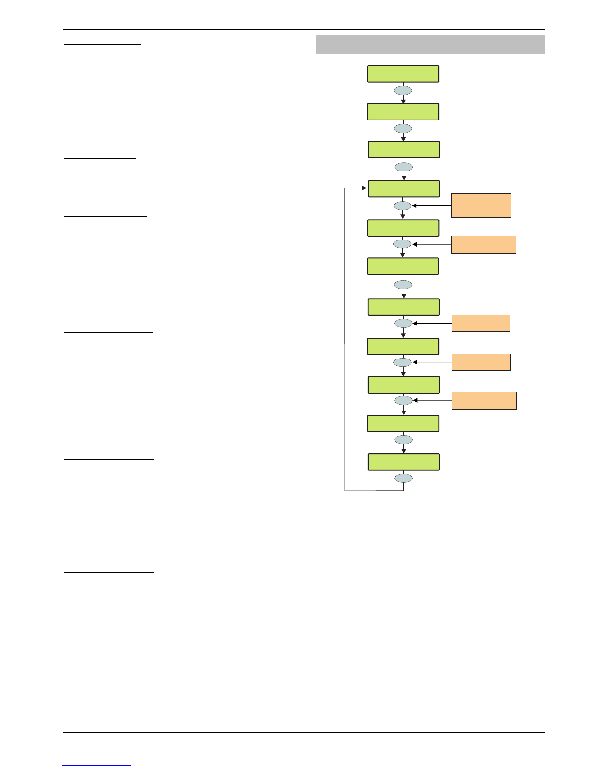
Premier 640 Installation Manual Programming the Control Panel
INS344 45
34 - Armed = Coms
When Areas are assigned to ‘Armed = Coms’ the system will
respond as follows:
• Communications and outputs (Alarm, Confirmed etc.) for
ALL areas will only operate when all of the assigned areas
are armed.
When No Areas are assigned to ‘Armed = Coms’ the system
will respond as follows:
• Communications and outputs (Alarm, Confirmed etc.) for
ALL areas will operate as normal.
35 - 2-Wire Smoke
Areas assigned to ‘2-Wire Smoke’ will register a Fire Alarm
when any 2-Wire Smoke detector activates.
Areas not assigned to ‘2-Wire Smoke’ will not register a Fire
Alarm when a 2-Wire Smoke detector activates.
36 - Faults Eng Reset
Each area can be programmed for Engineer or User reset
following any Fault. Areas Assigned to ‘Faults Eng Reset’ will
respond as follows:
• The assigned areas can only be reset using an Engineer
code
If ‘Anti-code Reset’ is enabled (option 11) the assigned
areas can also be reset using the Anti-code
Areas not assigned to ‘Faults Eng Reset’ can be reset with
any User code that is valid for those areas.
37 - No ATS Eng Reset
Each area can be programmed for Engineer or User reset
following a “No ATS Available” fault (ATS = Alarm
Transmission System). Areas Assigned to ‘No ATS Eng
Reset’ will respond as follows:
• The assigned areas can only be reset using an Engineer
code
If ‘Anti-code Reset’ is enabled (option 11) the assigned
areas can also be reset using the Anti-code
Areas not assigned to ‘No ATS Eng Rst’ can be reset with any
User code that is valid for those areas.
38 - AC Fail Eng Reset
Each area can be programmed for Engineer or User reset
following an AC Mains Fail. Areas assigned to ‘AC Fail Eng
Reset’ will respond as follows:
• The assigned areas can only be reset using an Engineer
code
If ‘Anti-code Reset’ is enabled (option 11) the assigned
areas can also be reset using the Anti-code
Areas not assigned to ‘AC Fail Eng Reset’ can be reset with
any User code that is valid for those areas.
39 - Mask When Armed
Areas assigned to ‘Mask When Armed’ will register a Masking
fault when the selected areas are armed and a Masking Fault
occurs.
Areas not assigned ‘Mask When Armed’ will never register a
Masking fault when the selected areas are armed and a
Masking Fault occurs
Time Arm Area
YES to Select:Area Programming
Yes
Yes
Area Programming
Time Arm Areas
Arm Profile01 by
timer
5
jkl
Yes
Press NO to change
timer number
6 mno
Area Programming
Timers
Arm Profile03 by
timer
Yes
Arm Profile03 by
timer 5
and Disarm 03 by
timer
Arm Profile03 by
timer > 5
3 def
Yes
Use keys 1 - 8 to select
a timer e.g. 3 = Timer 3
Press YES again to
confirm
and Disarm 03 by
timer > 3
Yes
and Disarm 03 by
timer 3
Enter the Area Profile or
Use the key
ie 03 selects Profile 03
U
??
No
Arm Profile03 by
timer >
Press YES to select
the disarmed by timer
The alarm system as a whole or any number of individual
areas can be automatically armed or disarmed using the built
in control timers.
The Premier 640 has 8 independent control timers that may
be configured to switch on and off at different points of the
day and operate on different days of the week (see page 52
for programming details).
Page 46
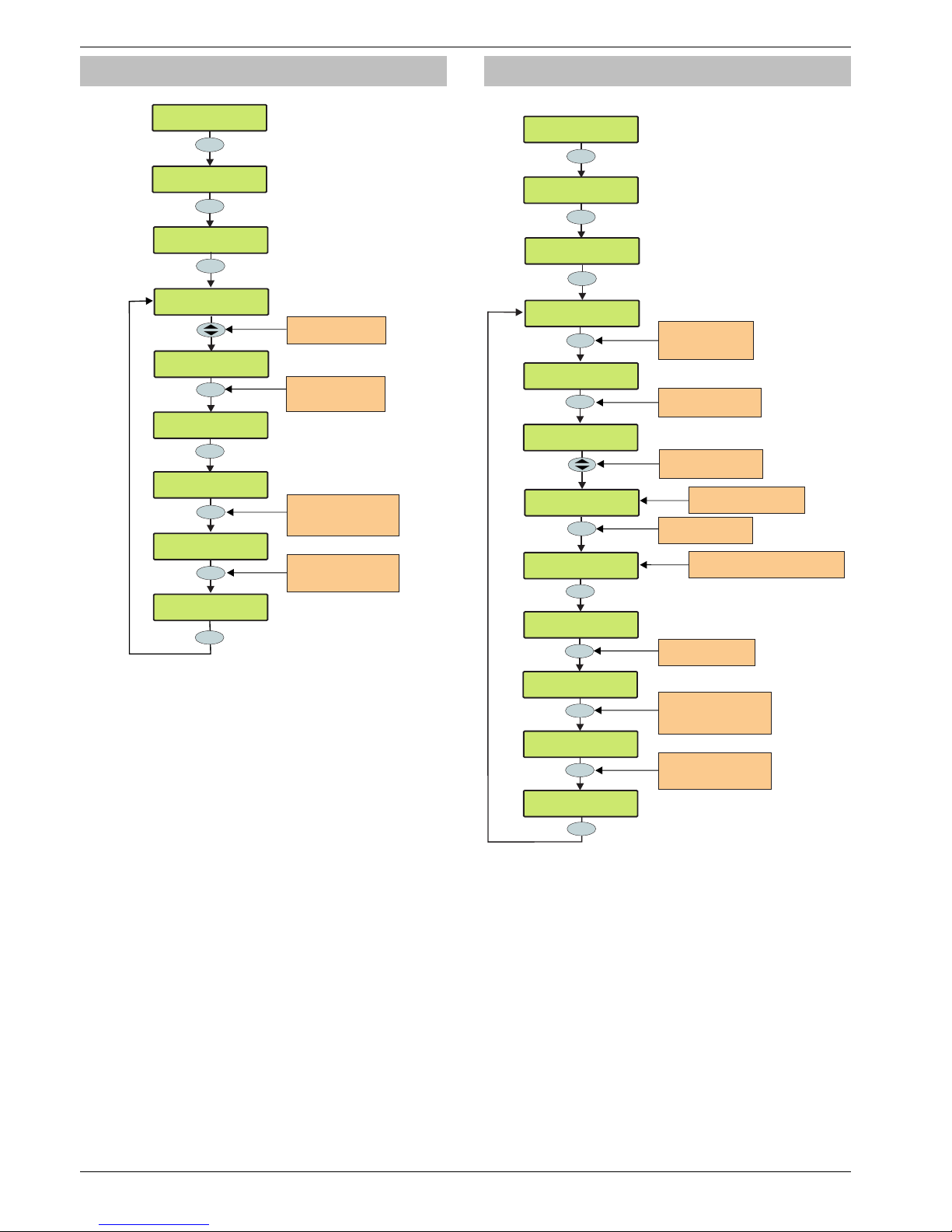
Programming the Control Panel Premier 640 Installation Manual
46 INS344
Area Text
YES to Select:Area Programming
Yes
Area Programming
Area Text
No
7 pqrs
Area Programming
Timers
Text for Area A1
Text for Area B2
Yes
Use the AREA key to
Jump a block of 8 areas
(A2-B2, C1-D1 etc)
Use the SCROLL key to
select an area
Area
Text for Area A1
Omit
^Edit Text >TXT
^Edit Text >ABC
Use keys 0 - 9 to program
text the same way that a
mobile phone works
????
Reception
Edit Tex^ >ABC
Use Omit key to switch
between predictive text
(TXT) and character (ABC)
Entry
Yes
Text may be assigned to each of the areas on the system.
This allows the user to select the areas by description instead
of a letter. A maximum of 16 characters can be programmed
for each of the areas.
Text is programmed in a similar way to mobile phones. Select
characters by pressing the corresponding key the
appropriate number of times (to select a character on the
same key, press
%
to move the cursor along).
Area Profiles
YES to Select:Area Programming
Yes
???
Area Programming
Area Profiles
* * Area 01 * *
01:<A:1.......
Yes
Press NO to change
Profile setup
8
tuv
Area Programming
Timers
* * Area 03 * *
03:<A:..3.....
Yes
Main Warehouse
03:>C:1.3....8
* * Area 03 * *
03:>C:........
Enter the Area Profile or
Use the key
ie 03 selects Profile 03
U
??
No
* * Area 03 * *
03:>A:..3.....
Use keys 1-8 to select
the areas in the group
Use the key to
change the area group
U
Top line=Profile text
Bottom line=included areas
Top line=Area text for area just added
Bottom line=included areas
* * Area 03 * *
03:>C:........
Omit
* * Area 03 * *
^Edit Text >TXT
Omit
* * Area 03 * *
^Edit Text >ABC
???
Lower Floor
Edit Text ^ >ABC
Yes
Press OMIT at any time
to edit Profile text
Use keys 0 - 9 to program
text the same way that a
mobile phone works
Use Omit key to switch
between predictive text
(TXT) and character (ABC)
Entry
Area profiles are used to define homogeonous groups of
areas that belong to an entity such as a company,
department or floor of a building.
Each profile can be annotated with a 16 character name.
80 Area profiles are provided. Profile number 00 and 80 are
special and cannot be edited (00-No Areas, 80-All Areas)
All other areas can be programmed with any combination of
up to 64 Areas.
When an area profile is assigned to a User, Keypad or
Expander, all of the areas assigned to the profile will are also
assigned to the User, Keypad or Expander. Any changes to
the profile will then be automatically carried through to all of
its associations.
Page 47
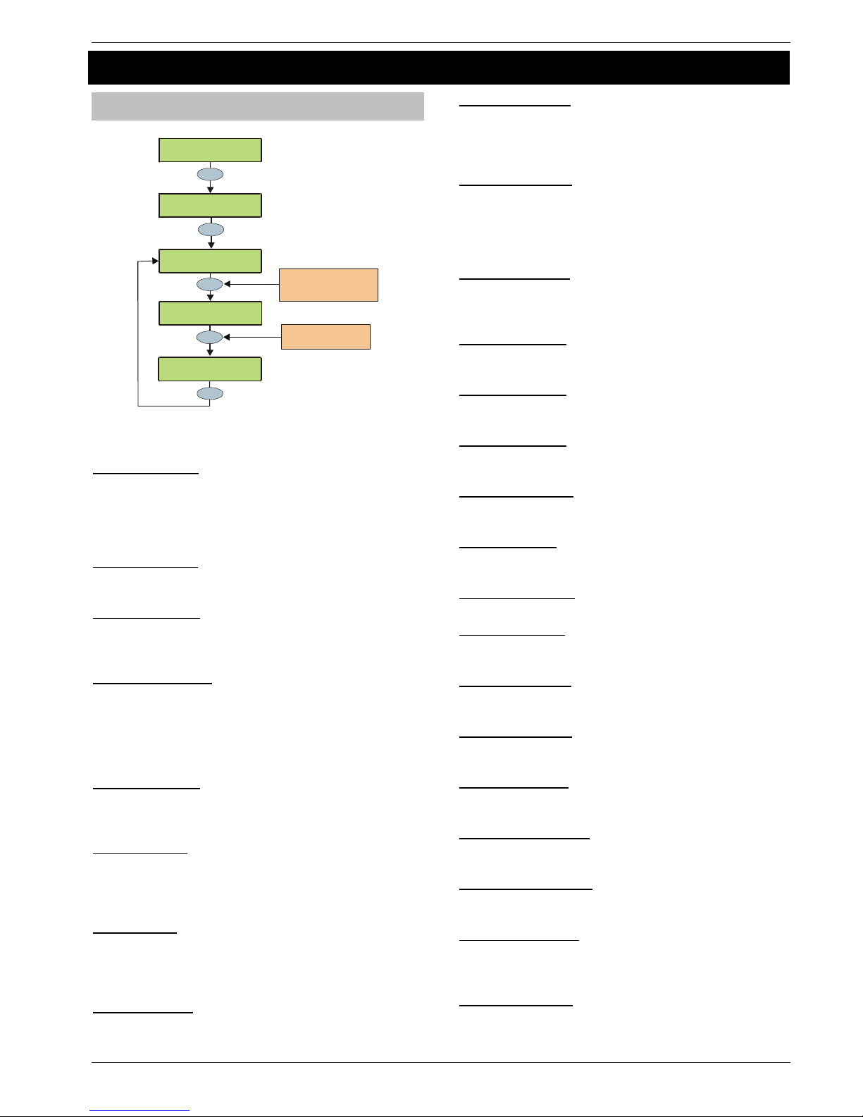
Premier 640 Installation Manual Programming the Control Panel
INS344 47
5.3 Global Options
System Timers
>73!:0!3$-$6:Z[
V-0E(-!HO:508<
Yes
Yes
V-0E(-!HO:508<
3=<:$/!"5/$)<
7P5:!3$::-$!"5/$
!!!%%A!3$608Da<b
V-0E(-!N$--!C-=1
!!!%%%!'58#:$a<b
Yes
V-0E(-!N$--!C-=1
!W!%%A!'58#:$a<b
Use the YES key to move
to the next timer or use
the SCROLL key to search
Yes
Enter a new timer value
e.g. 005 = 5 Minutes
???
These timers control various timing and delay functions. Each
timer can be programmed for any value between 000 and 999.
1 - Exit Settle Time
When using the ‘Entry/Exit’ or ‘Exit Terminator’ arming mode,
some detectors along the exit route can remain active for a
number of seconds following activation. This timer ensures that
the detectors are given time to deactivate before the
system/area arms.
2 - Global Bell Dly.
This timer controls the delay between an Intruder
alarm occurring and the ‘Bell/Strobe’ output activating.
3 - Global Bell Dur.
This timer controls the duration of the ‘Bell’ output after an
alarm has occurred and any programmed ‘Global Bell Delay’
time has expired.
4 - Double Knock Dly
If a zone has the ‘Double Knock’ attribute an alarm will only occur
if the zone activates twice within this time window or once for the
duration of this time window.
!
If multi knocks has been set up (see page 51 for details)
the zone may have to be activated more than twice.
5 - Beam Pair Time
If a zone has the ‘Beam Pair’ attribute, an alarm will only
occur if another zone with the ‘Beam Pair’ attribute (assigned
to the same area) is activated within this time window.
6 - Activity Delay
If a zone has the ‘Activity’ attribute and it is not activated during
this timer and ‘Config. option 14’ has been set to ‘View Act. Fault’
(see page 49 for details), it will be indicated to the user when
they try to arm the system/area.
7 - Abort Delay
When an Intruder alarm occurs this timer is started, if the area
is disarmed within this time window an ‘Abort’ event will be
reported to the Alarm Receiving Centre. If the system is
disarmed after this period the ‘Abort’ event is not reported.
8 - Courtesy Time
This timer controls the duration of the ‘Courtesy’ output type.
The courtesy output activates whenever a keypad is being
used and during the entry mode.
9 - Defer Arming By
If an area tries to ‘Time Arm’ and a valid User code is entered,
this timer is started and the ‘Time Arming’ procedure is
postponed. When this timer expires, the system/area will try to
arm itself again.
10 - Auto Arm Delay
When an area assigned to ‘Auto Arm Areas’ is disarmed (see
page 43 for details) this timer is started. Every time a detector in
that area is activated, the timer is restarted. If the timer is allowed
to expire i.e. no detectors in the assigned area are activated, the
area will arm itself.
11 - Menu Time Out
This timer controls the length of time that a user can remain
in a menu before the system automatically returns to the
normal day mode.
12 - Pulse Period 1
This timer controls how long any output with the
‘Pulse Period 1’ attribute assigned to it will activate for.
13 - Pulse Period 2
This timer controls how long any output with the
‘Pulse Period 2’ attribute assigned to it will activate for.
14 - Pulse Period 3
This timer controls how long any output with the
‘Pulse Period 3’ attribute assigned to it will activate for.
15 - ATS Fault Delay
This timer controls the delay between a line fault occurring
and an audible indication being generated by the system.
16 - AC Off Delay
This timer controls the delay between an AC Mains failure
occurring and an audible indication being generated by the
17 - Batt Test Period
This timer controls the frequency of the dynamic battery test.
18 - Batt Test Time
This timer controls how long the dynamic battery test is
carried out for.
19 - Soak Test Time
This timer controls the number of days a zone with the ‘Test’
attribute will remain on test for.
20 - Service Interval
This timer controls the frequency of the ‘Service Required’
condition occurring.
21 - Test Call Every
This timer controls how often a test call is made to the
monitoring station. 024 = daily etc.
22 - Min. Random Time
This timer controls the minimum length of time
that the ‘Random’ output attribute will activate for.
23 - Max. Random Time
This timer controls the maximum length of time that the
‘Random’ output attribute will activate for.
24 - Door Strike Time
This timer controls the length of time that the ‘Door Strike’
output will activate for whenever a code with the ‘Door Strike’
attribute is entered.
25 - Zone Response
This timer controls the length of time that a zone with the
‘Quick Resp.’ attribute, has to be activated for, in
order to be recognised by the control panel.
Page 48
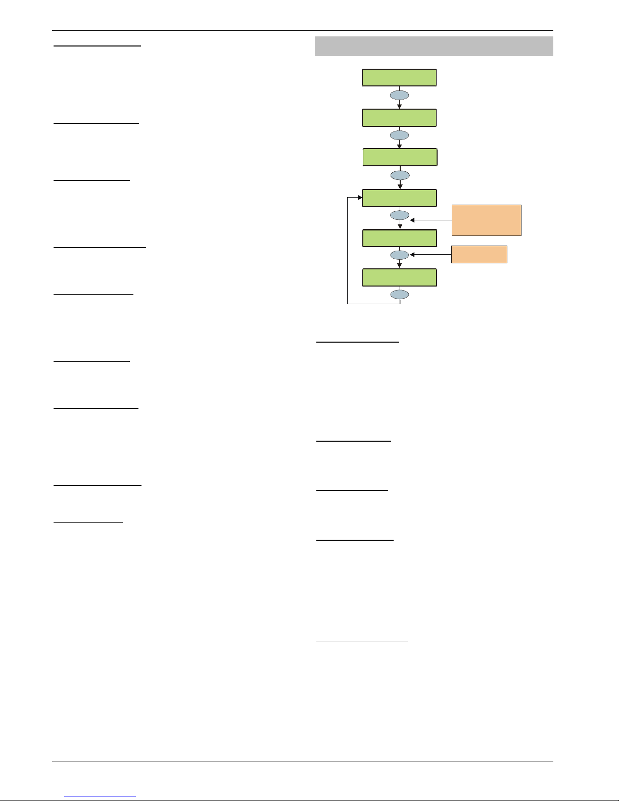
Programming the Control Panel Premier 640 Installation Manual
48 INS344
26 - Keypad PA Delay
When keypad ‘option 6’ is programmed as ‘PA Delayed’ (see
page 57 for details), and a keypad PA alarm (1 & 3) is
activated, this timer starts. If a User code is entered before
this timer expires, no PA alarm will occur. However, if a User
code is not entered before this timer expires, a PA alarm will
occur.
27 - Confirmation Dly
When an Intruder alarm occurs, this timer starts. If a second
(different) zone is activated within this time window, the
‘Confirmed’ output will activate. When this timer
expires, the ‘Confirmed’ output will no longer activate.
28 - Warning Delay
When a Custom zone with the ‘Warning Req’ attribute (see
page 37 for details) activates, this timer is started. If the zone
is still active when this timer expires a warning tone or alarm
will occur and the Warning Output (see page 64 for details)
will activate.
29 - Keypad Lock Time
When code tampers are programmed to lockout the keypad
(see page 49 for details), the keypad will lock out for the
duration of this timer.
30 - Eng. log off Dly
This timer starts when an Engineers code is entered. When the
timer expires the engineer is automatically logged out of
engineer’s mode. This timer is suspended if there are tamper
faults on the system allowing the engineer to remain in
engineer’s mode indefinitely whilst on site.
31 - Fire Bell Delay
This timer starts when a fire alarm is generated in a particular
area. When the timer expires sounders are activated in ALL
areas.
32 - Forced Entry Dly
When a zone with the ‘Guard’ attribute (see page 36 for
details) activates, this timer is started. For the duration of this
timer, any ‘Entry/Exit 1 or 2’ zone with the ‘Entry/Exit 2’
attribute (see page 36 for details) will become a ‘Guard’ zone.
When this timer expires, the ‘Entry/Exit 1 or 2’ zone will revert
back to its normal mode of operation.
33 - Supervision Time
This timer controls the frequency at which the RadioPLUS
detectors are required to report in to the control panel.
34 - Poll IP Every
This timer controls the frequency that the ComIP Polls the
ARC.
System Config.
>73!:0!3$-$6:Z[
V-0E(-!HO:508<
Yes
Yes
1
V-0E(-!HO:508<
3=<:$/!"5/$)<
V-0E(-!HO:508<
3=<:$/!,08B591
Yes
,08B59#)(:508!%%
L0!N$--!3$:!2(5-
Press NO to change
the config. option
No
Yes
,08B59#)(:508!%c
LT'!5<!\8-06G$D
Enter a configuratio n
number or use the
SCROLL key to search
e.g. 09 = NVM Unlocked
,08B59#)(:508!%c
LT'!5<!?06G$D
??
These options control how various system functions work.
00 - No Bell Arm Fail
If an area fails to arm, an Internal alarm will occur and the
‘Strobe’ output will activate.
Bell on Arm Fail
If an area fails to arm, an Internal alarm will occur and the
‘Bell’ output will activate for 10 seconds.
!
The ‘Strobe’ output will also activate for 5 seconds to
indicate that the system has armed/disarmed.
01 - Bell is an SAB
The ‘Bell’ output on the control panel applies 0V when active.
Bell is an SCB
The ‘Bell' output on the control panel removes 0V when active.
02 - Clock is 24Hr
The system time is displayed in the 24-Hour format.
Clock is 12Hr (Default)
The system time is displayed in the 12-Hour format.
03 - Auto BST/GMT
The system clock will adjust itself at the beginning and the
end of the summer (the clock will automatically gain 1Hr on
the last Sunday in March and lose 1Hr on the last Sunday in
October.
Manual BST/GMT
The system clock will not adjust itself at the beginning and
the end of the summer (the clock will have to be adjusted
manually).
04 - View Armed Areas
When the system is part armed, the areas that are armed are
displayed and alarm information is displayed before a valid
User code is entered.
Hide Armed Areas
When the system is part armed, the areas that are armed are
not displayed and alarm information is only displayed after a
valid User code has been entered.
Page 49

Premier 640 Installation Manual Programming the Control Panel
INS344 49
05 Global Bell Time
When all areas are armed, the system uses the ‘Global Bell
Delay’ and ‘Global Bell Duration’ timers (see page 47 for details).
Area Bell Time
When all areas are armed, the system uses the ‘Area Bell
Delay’ and ‘Area Bell Duration’ timers (see page 39 for details).
06 - 24Hr Omit Global
‘24-Hour’ type zones can be omitted from any keypad.
24Hr Omit Local
Only keypads assigned to the same area as the
‘24-Hour’ type zones can be used to omit the zone.
07 - Remove Omits
When zones have been ‘Omitted’ by a user, the zones will be
automatically reinstated by the system when the area they
are assigned to is next disarmed.
Leave Omits
When zones have been ‘Omitted’ by a user, the zones will
remain omitted until the user reinstates them.
08 - Override Com Dly
If an area is ‘Fully’ armed and an Intruder alarm occurs in that
area, Intruder alarm events (for that area) are reported to the
Alarm Receiving Centre immediately.
Enforce Com Dly
If an area is ‘Fully’ armed and an Intruder alarm occurs in that
area, Intruder alarm events (for that area) are reported to the
Alarm Receiving Centre after any programmed ‘Coms delay’
has expired (see page 39 for details).
09 - NVM is Unlocked
The factory default settings can be reloaded by pressing the
Factory Restart button during power up.
NVM is Locked
The factory default settings cannot be reloaded by pressing
the factory default button during power up.
!
If the NVM is locked and the Engineer User code has
been lost or forgotten, the control panel will have to be
returned to Texecom to be unlocked.
10 - Engineer Only
Access to the Engineers Programming menus can be
obtained by just entering the Engineer User code.
User + Engineer
Access to the Engineers Programming mode can only be
obtained, if a User (with the ‘Engineer Access’ attribute) has
authorised engineer access (see page 86 for details).
11 - Chime Audible
Zones programmed with the ‘Chime 2 or 3’ attribute will only
generate a Chime tone.
Chime Visible (Default)
Zones programmed with the ‘Chime 2 or 3’ attribute will
generate a Chime tone. The keypad will also display the
number of the zone that was activated.
12 - Omit Tampers No
A user cannot omit Tamper faults on a zone.
Omit Tampers Yes
A user can omit Tamper faults on a zone.
13 - Offline Printing
If a printer is plugged onto the control panel, nothing will be
printed unless a printout is requested (see page 98 for
details).
Online Printing
If a printer is plugged onto the control panel, anything that is
logged in the event log is also printed at the same time.
14 - Hide Act. Fault
If a zone with the ‘Activity’ attribute is not activated during the
‘Activity Delay’ time window, the area that the zone is
assigned to can still be armed. However, this fault will be
indicated to the user when they try to arm the area.
View Act. Fault
If a zone with the ‘Activity’ attribute is not activated during the
‘Activity Delay’ time window, the area that the zone is
assigned to cannot be armed. This situation can only be
overcome by activating the zone.
15 - Hide Exit Errors
If a user tries to arm an area and there are zones activated,
the exit mode will continue (giving a visual and audible
indication that there is a problem).
View Exit Error
If a user tries to arm an area and there are zones activated,
the exit mode is suspended until all of the zones are secure.
16 - Enable Code Tampers
24 invalid key presses on a keypad will cause a Code Tamper
condition (see option 17).
No Code Tampers
A Code Tamper condition will never occur when the keys on
a keypad are pressed more than 24 times.
17 - Code Tamper Alarm
A Code Tamper condition will cause a Tamper alarm in the
areas that the keypad is assigned to.
Code Tamper Lockout
A Code Tamper condition will cause the keypad to lockout for
5 minutes.
18 - Areas A-H & I-P
The first 8 areas will be displayed as letters A through to H and
the last 8 areas will be displayed as letters I through to P.
Areas 1-8 & I-P
The first 8 areas will be displayed as numbers
1 through to 8 and the last 8 areas will be displayed as letters
I through to P.
19 - Auto Area Select
When an Engineers code is entered to gain access to the
programming mode, ALL Zones and Tampers are disabled
i.e. if any Tampers, PA, Fire or Medical Alarms are activated NOTHING WILL HAPPEN.
Man. Area Select
When an Engineers code is entered to gain access to the
programming mode, the Engineer will have to select which
areas are going to be worked on.
!
Zones and Tampers are only disabled for the selected
areas all other areas will respond to zone activations
and tampers as normal.
Page 50

Programming the Control Panel Premier 640 Installation Manual
50 INS344
20 - Predictive Text
When in text editing mode, the control panel will
automatically select predictive text.
Manual Text Edit
When in text editing mode, the control panel will
automatically select normal text.
21 - Short = Tamper
The control panel will see a zone that is in the short circuit
condition as a ‘Tamper’.
Short = Active
The control panel will see a zone that is in the short circuit
condition as ‘Active’.
22 - R/R=Reset Only
When 0V is applied to the control panel R/R input, any areas
programmed for anti-code reset (see page 43 for details) that
are in alarm, will be reset.
R/R=Silence/RST
When 0V is applied to the control panel R/R input any areas
programmed for anti-code reset (see page 43 for details) that
are in alarm, will be silenced. When 0V is applied to the R/R
input a second time, the areas will be reset (this would
normally be used when Audio Verification is required).
23 - User Code Pulse
The control panel will see a zone that is in the short circuit
condition as ‘Active’.
User Code Latch
The control panel will see a zone that is in the short circuit
condition as a ‘Tamper’.
24 - Timed Test Call
A test call to the Alarm Receiving Centre will occur every time
the ‘Test Call Every’ timer expires.
Test Call = CT7
A test call to the Alarm Receiving Centre will occur every time
‘Control Timer 7’ activates.
25 - Batt Test Timed
A battery test will occur every time the ‘Batt Test Period’ timer
expires.
Batt Test = Disarm
A battery test will occur every time the system is disarmed or
after the ‘Batt Test Period’ timer has expired (whichever
occurs first).
26 - Bell = 1st Alarm
The ‘Bell’ and ‘Strobe’ outputs will activate after an Intruder
alarm (1st Alarm) occurs.
Bell = 2nd Alarm
The ‘Bell’ and ‘Strobe’ outputs will activate after a Confirmed
alarm (2nd Alarm) occurs.
27 - SNDR = 1st Alarm
The internal sounders will sound after an Intruder alarm (1st
Alarm) occurs.
SNDR = 2nd Alarm
The internal sounders will sound after a Confirmed alarm
(2nd Alarm) occurs.
28 - Conf. = Instant
Following the arming of the system/area, if two zones activate
(causing a Confirmed alarm), the signal will be reported to the
Alarm Receiving Centre immediately.
Conf. = Delayed
Following the arming of the system/area, if two zones activate
(causing a Confirmed alarm), the signal will only be reported
to the Alarm Receiving Centre after the ‘Abort’ time has
expired.
29 - Abort=Eng.Reset
An Intruder alarm that is aborted can only be reset by an
Engineer/Anti-code.
Abort=User Reset
An Intruder alarm that is aborted can be reset by any User.
30 – Auto AV Output
When using the AV Module, if a microphone is remotely
selected, the corresponding output automatically activates.
Manual AV Output
When using the AV Module, if a microphone is remotely
selected, the corresponding output must be activated
manually.
31 - Clock = 50Hz
The internal clock on the control panel runs from the 50Hz
main frequency.
Clock = Crystal
The internal clock on the control panel runs from the built-in
crystal.
32 - 80 Column Print
Select this option when connecting an 80 Column printer to
the control panel.
40 Column Print
Select this option when connecting an 40 Column printer to
the control panel.
33 - Disable Text
Areas that are armed are displayed as letters on the bottom
line of the display i.e. ‘Armed: AB.D…’
Enable Text
Areas that are armed are displayed using their assigned text
on the bottom line of the display i.e. ‘Armed: Garage’, ‘Office’
etc. (a different area is displayed every second).
34 - EN50131 Disabled
The Control Panels EN50131 options are disabled.
EN50131 Enabled
Keypad display ‘blanking’ is enabled i.e. the keypad will only
display the time, date and the banner message. If information
is available to be viewed i.e. AC Mains Fail, Line Fault,
System Faults etc. the keypad will bleep every 30 seconds
and display ‘System Alerts’, this information can only be
viewed after a valid user code has been entered. The keypad
display will then ‘blank’ again 30 seconds after.
The bell output will not activate, if an alarm occurs during the
entry mode.
Duress Codes can only be programmed by an engineer
35 - 2nd Zone = Confirm
After the entry timer has expired, activation of 2 more zones is
required to generate a Confirmed alarm
1st Zone = Confirm
After the entry timer has expired, activation of 1 more zone is
required to generate a Confirmed alarm
36 - Keypads Global
Keypads show information for all areas.
Keypads Local
Keypads only show information that is relative to the area that
the keypad is assigned to.
37 - Panel Grade 3
All options relating to PD6662: 2004/EN 50131-1 Grade 3 are
enabled automatically. Also, the Premier Anti-code reset
becomes a 6-digit number and all user codes can only be
programmed as 5 or 6 digits.
Page 51
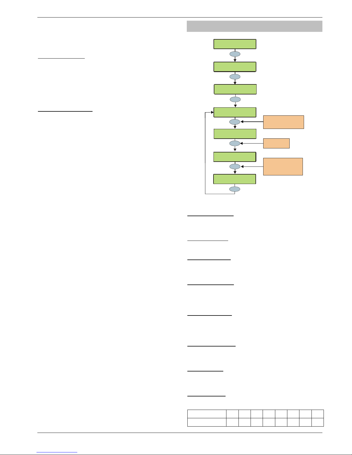
Premier 640 Installation Manual Programming the Control Panel
INS344 51
Panel Grade 2
All options relating to PD6662: 2004/EN 50131-1 Grade 3 that
are not required for Grade 2 are disabled automatically. Also, the
Premier Anti-code reset becomes the standard 4 digit number
and all user and engineer codes can be 4, 5 or 6 digits.
38 - Disable FOB PA
When a ‘RadioPlus’ Transmitter FOB is being used with the
alarm system, the Panic Alarm (PA) function i.e. Pressing
buttons 1 and 2 together, is disabled.
Enable RF FOB PA
When a ‘RadioPlus’ Transmitter FOB is being used with the
alarm system, the Panic Alarm (PA) function i.e. Pressing
buttons 1 and 2 together, is enabled.
39 - Armed Mask=Fault
If an Anti-masking signal is detected when the system is
armed, the control panel will generate a Fault response.
Armed Mask=Alarm
If an Anti-masking signal is detected when the system is
armed, the control panel will generate an Alarm response.
System Options
>73!:0!3$-$6:Z[
V-0E(-!HO:508<
Yes
Yes
2
abc
V-0E(-!HO:508<
3=<:$/!"5/$)<
.D45<0)=!T0-#/$
!!!!?$4$-!d!A
Yes
V-0E(-!HO:5
08<
3=<:
$/!HO:508<
Use the YES key to move
to the next option or use
the SCROLL key to search
Yes
No
,K5
/$!T0-#/$
!!!!?$4$-!d!*
,K5/$!T0-#/$
!!!!?$4$-!d!X
Press NO to edit
the volum e lev el
Enter a value or use the
SCROLL key to increase
or decrease the value
e.g. 8 = Full Volume
7
pqrs
,K5
/$!T0-#/$
!!!!?$4$-!dW*
These options control various system functions.
1 - Advisory Volume
Controls the volume of advisory tones (entry/exit etc.) from
loudspeakers connected to the control panel (Alarm tones are
always full volume). 1 = min, 8 = max.
2 - Chime Volume
Controls the volume level of Chime tones from ALL
loudspeakers. 1 = min, 8 = max.
3 - No. Of Re-Arms
Controls the number of times that a zone will re-arm. Once the rearm limit has been reached, the zone is ‘Locked Out’ and will not
cause any further Intruder alarms.
4 - Anti-code Resets
Limits how many times a user can perform an Anti-code reset.
Once this limit is been reached, the system can only be reset
using an Engineer code. This counter is reset every month or
whenever an Engineers code is entered.
5 - Multiple Knocks
Controls how many times, a zone with the ‘Double Knock’
attribute, must be activated, before an alarm occurs. The
multiple knock count can be applied to zones on an area
basis, see page 44 for details.
6 - Clock Adjustment
Adjusts the accuracy of the clock by subtracting or adding
time in seconds at midnight every night. 0 = -50, 50 = 0 (no
correction), 100 = +50.
7 - Quick Count
Set the number of 10milli Second pulses that are required
within 30 Seconds in order for a zone with the ‘Quick
Response’ attribute to activate.
8 - Modem Level
When using a Com2400 this option allows adjustment to the
attenuation of the modem.
Modem Level 2 1 0 7 6 5 4 3
Attenuation (dB) +4 +2 0 -2 -4 -6 -8 -10
Page 52
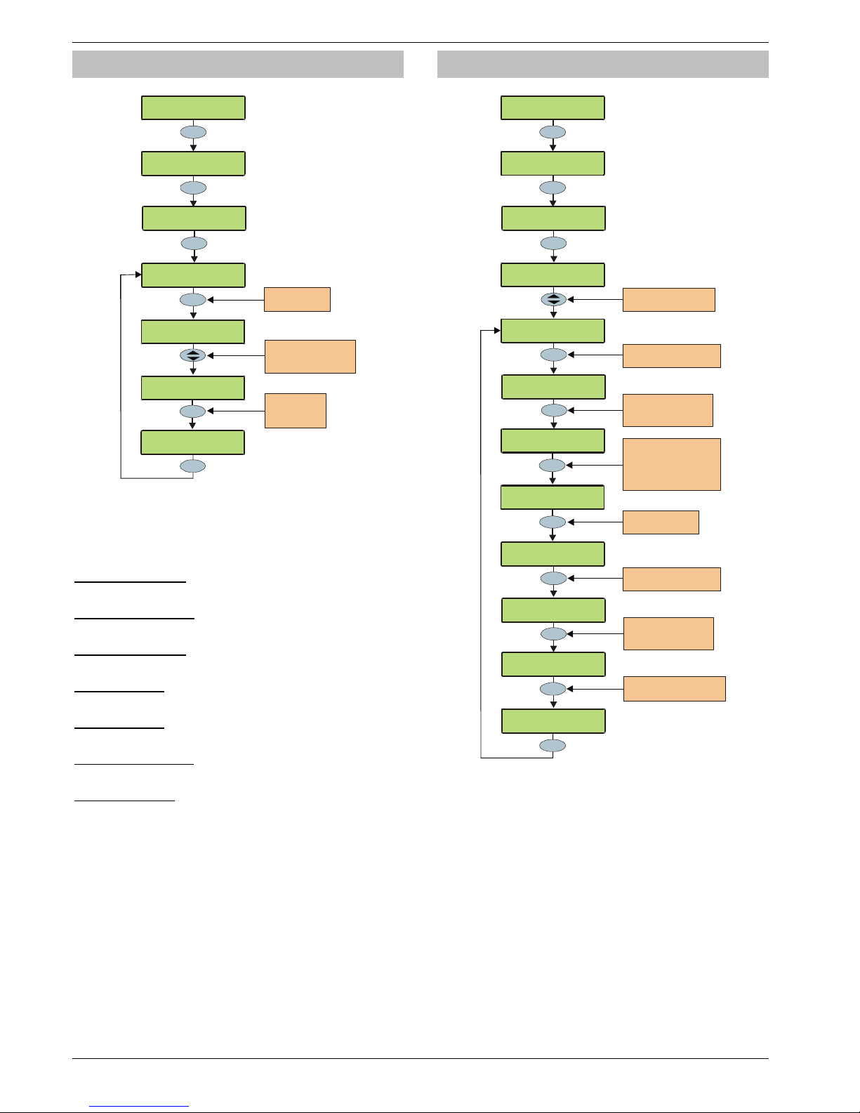
Programming the Control Panel Premier 640 Installation Manual
52 INS344
Monitor Hardware
>73!:0!3$-$6:Z[
V-0E(-!HO:508<
Yes
V-0E(-!HO:508<
'085:0)!e()DJ()$
Yes
3
def
V-0E(-!HO:508<
3=<:$/!"5/$)<
No
Yes
'085:
0)!e()DJ()$
!.!.!2!N!.!?!M
No
Press NO to edit
the options
Use keys 1 - 8 to select
an attribute or use the
SCROLL key to search
Press NO to
select/deselect
the option
."3!I(:K!2(#-:<
W.!.!2!N!.!?!M
N$--!"(/O$)
!I!.!2WN!.!?!M
N$--!"(/O$)
!I!.!2WM!.!?!M
The control panel monitors many inputs for fault conditions
i.e. the panel lid tamper, bell tamper, aux fuse etc.
Each one of these options can be disabled to overcome
problems related to the devices being monitored.
P - ATS Path Faults
The Alarm Transmission System is monitored for faults.
A - AC Power Failure
The AC Mains is monitored for faults.
F - Aux Fuse Blown
The Auxiliary Fuse/PTC is monitored for faults.
B - Bell Tamper
The external sounder tamper loop is monitored for faults.
A - Aux Tamper
The auxiliary tamper loop is monitored for faults.
L - Panel Lid Tamper
The control panel lid tamper is monitored for faults.
B - Battery Faults
The battery is monitored for faults.
Control Timers
>73!:0!3$-$6:Z[
V-0E(-!HO:508<
Yes
Yes
4
ghi
V-0E(-!HO:508<
3=<:$/!"5/$)<
,08:)0-!"5
/$)!+(
5<!H8!(:!W+fZ%%
Yes
V-0E(-!HO:5
08<
,08:)0-!"5
/$)<
Yes
Use keys 1 - 8 to select
the days 1 = Sunday
through to 7 = Saturday
(8 = Holi day Date)
e.g. 1 = Sunday
1
,08:)0-!"5
/$)!*(
5<!H8!(:!W+fZ%%
Use the SCROLL key to
select control timer 1 - 8
,08:)0-!"5/$)!*(
5<!H8!(:!W++ZA*
Enter the ‘a’ On time
for e.g. 1152 = 11:52 am
Press YES to select
the ‘a’ On Tim e
‘DAYS OF OPERATION’
"5/$)!*(!H8!C(=<
1111111111111111
"5/$)!*(!H8!C(=<
3#11111111111111
Yes
Yes
Use keys 1 - 8 to select the
days e.g. 3 = Tuesday
1
,08:)0-!"5
/$)!*(
5<!HBB!(:!W+*Z%%
Enter the ‘a’ Off Time
for e.g. 2134 = 9:34 pm
Press YES to select
the ‘a’ Off Time
‘DAYS OF OPERATION’
"5/$)*(!HBB!C(=<
1111111111111111
"5/$)*(!HBB!C(=<
1111"#1111111111
Press YES to select
the ‘a’ Off Time
,08:)0-!"5/$)!*(
5<!HBB!(:!W*+Zfg
????
????
The Premier 640 has 8 control timers. Each timer has two ON
and OFF times (a & b), and can be programmed to operate on
any day of the week. Once configured, the timers can be used to
arm or disarm areas, lockout users and control outputs.
!
When programming the Control Timers ON time,
pressing 2 will bring a ‘*’ up on the display. This ‘*’
indicates that the internal sounders will chime every
time the Control Timers ON time is reached.
When programming the Control Timers DAYS of
operation, pressing * will bring ‘HO’ up on the
display. This ‘HO’ indicates that the control timer will
operate on any programmed Holiday date.
Page 53
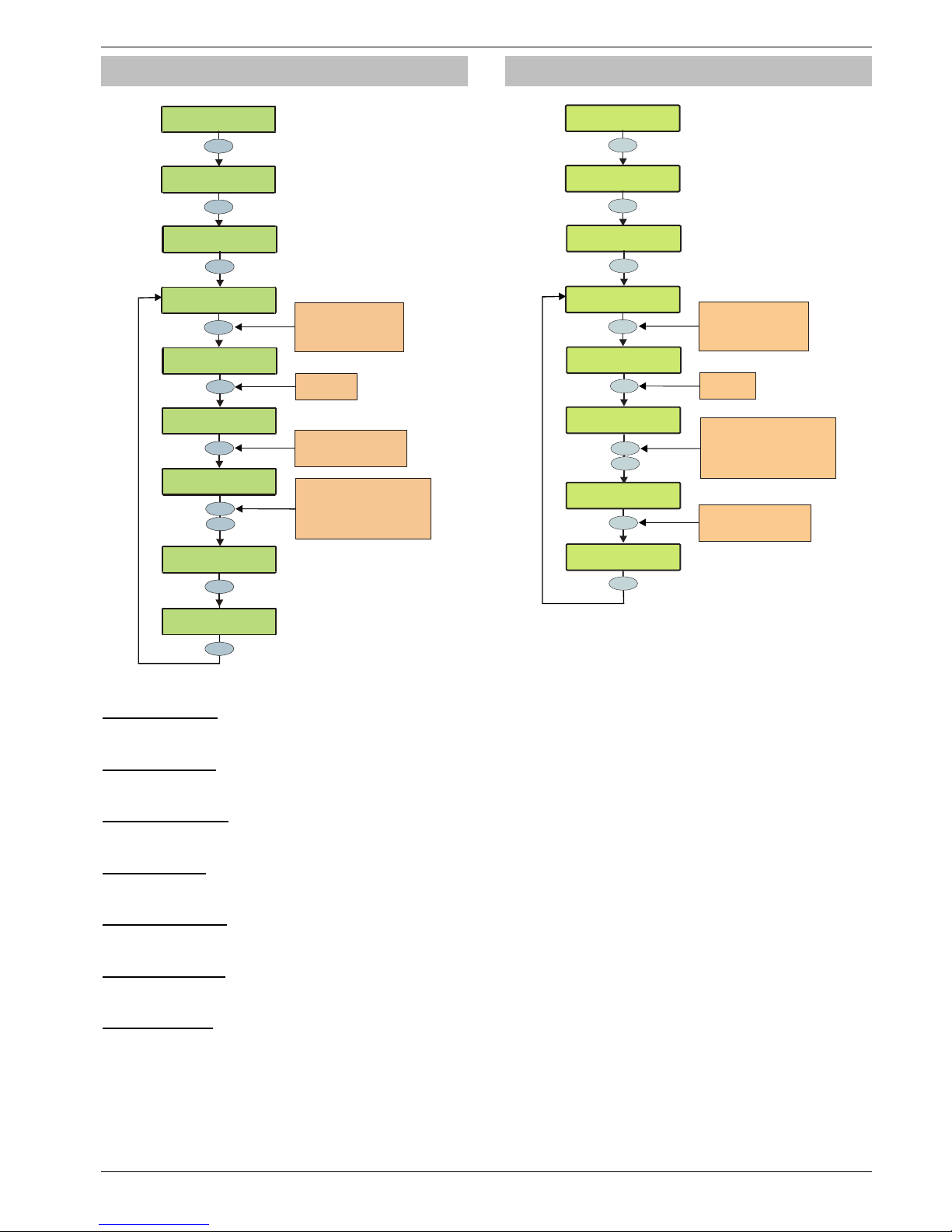
Premier 640 Installation Manual Programming the Control Panel
INS344 53
System Text
>73!:0!3$-$6:Z[
V-0E(-!HO:508<
Yes
Yes
5
jkl
V-0E(-!HO:508<
3=<:$/!"$P:
!>73!!:0!7C_"Z
;$<$:!'$<<(9$
Yes
h7D5:!"$P:!!W.N,
Use keys 1 - 6 to select
a text option or use the
SCROLL key to search
i.e. 5 = Banner Me ssage
4
ghi
No
!!!
.N,!.
!
7D5:!"hP:!!h.N,
Use keys 0 - 9 to program
text the same way that a
mobile phone works
Press YES to
edit the text
V-0E(-!HO:508<
3=<:$/!"5/$)<
!>73!!:0!7C_"Z
N(88$)!'$<<(9$
Press NO followed by YES
to clear the screen or keep
pressing NO to change between
upper case , lower ca se,
numerical and predictive text
Yes
????
????
!
!
7D5:!"$P:!!W,?;
Yes
.N,!.-()/<!*%%+
!
7D5:!"$P:!!W+*h
The system has 7 programmable messages.
1 - Reset Message
This 32-character message is displayed whenever the control
panel requires an Engineer reset.
2 - Anti-code Msg.
This 32-character message is displayed whenever the control
panel requires a Anti-code Reset.
3 - Service Message
This 32-character message is displayed whenever the control
panel requires Daytime reset.
4 - Location Text
This 32-character message is displayed whenever the
engineer views the location text in ‘Engineer Utils’.
5 - Banner Message
This 16-character message is displayed above the time and
date whenever the control panel is unarmed or fully armed.
6 - Part Arm Banner
This 16-character message is displayed above the time and
date whenever the control panel is part armed.
7 - Printer Header
This 16-character header will be printed whenever a log
printout is taken from the control panel or a Short Message
Service (SMS) text message is sent to a mobile phone.
Part Arm Text
YES to Select:Global Options
Yes
Yes
6
mno
Global Options
Part Arm Text
Evening Arm
Text for Part 1
No
^Edit Text >TXT
Bedtime Arm 2
Use keys 1 - 3 to select a
stay arm group or use the
SCROLL key to search
e.g. 3 = Stay Arm 3
3
def
Press No to
edit the text
Global Options
System Timers
Nightime setting
Edit Text >ab^
^Edit Text >ABC
Use keys 0 - 9 to program
text the same way that a
mobile phone works
Yes
????
Bedtime Arm 2
Text for Part 3
No
Press NO followed by YES
to clear the screen then keep
pressing NO to change between
upper case, lower case,
numerical and predictive text
Yes
Text may be assigned to Part Arm 1, 2 or 3 to allow the user
to select the correct Part Arm by description instead of
number. A maximum of 16 characters can be programmed
for each of the Part Arms.
!
The 3 Part Arm messages are global messages and will
appear whenever one of the part arms are selected
regardless of which area is being part armed.
Text is programmed in a similar way to mobile phones.
Select characters by pressing the corresponding key the
appropriate number of times (to select a character on the
same key, press
%
to move the cursor along).
Page 54
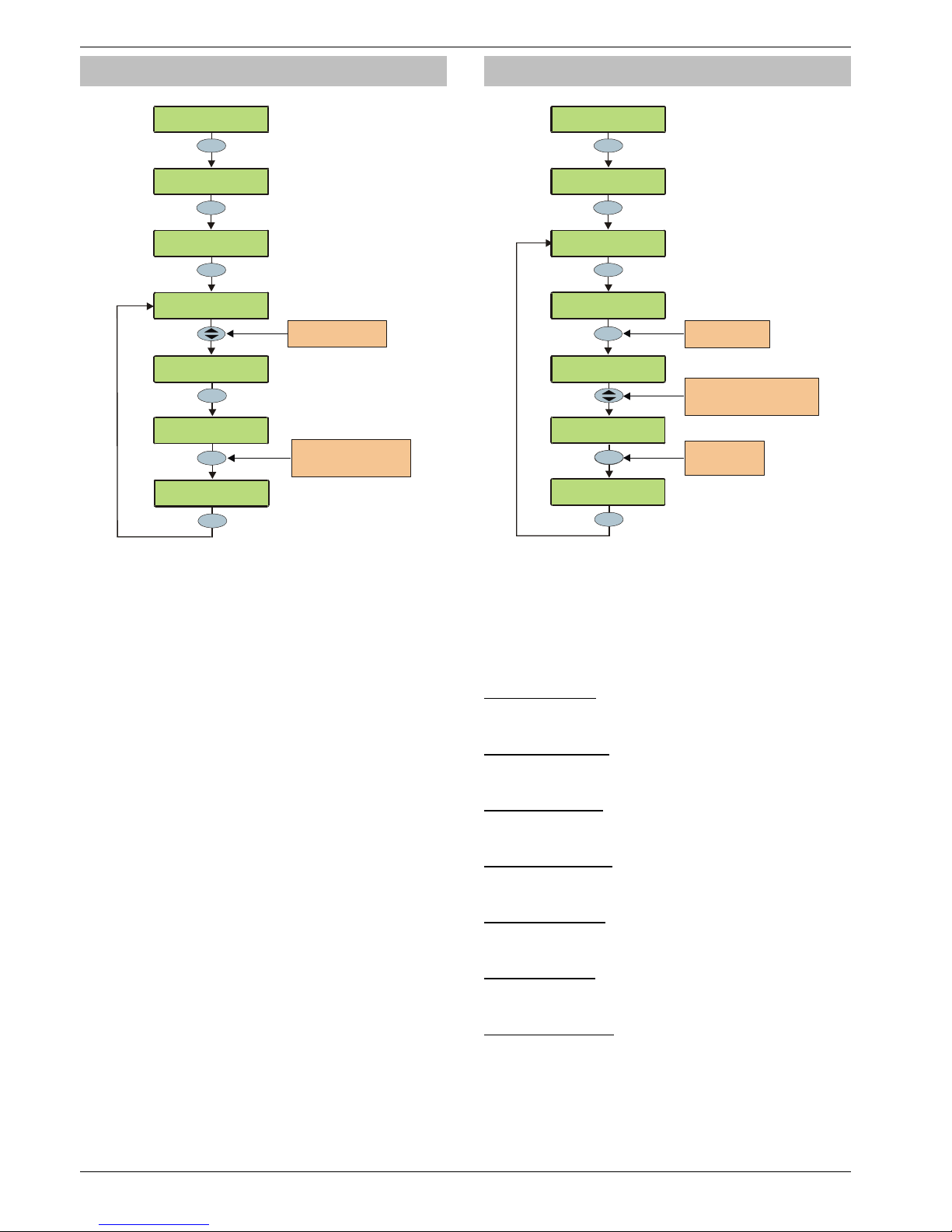
Programming the Control Panel Premier 640 Installation Manual
54 INS344
Holiday Dates
>73!:0!3$-$6:Z[
V-0E(-!HO:508<
Yes
V-0E(-!HO:5
08<
3=<:$/!"5/$)<
Yes
e0-5D(=!C(:$!fW
!!W!%%]%%]%%
Yes
Use keys 0 - 9 to enter the
new date DD/MM/YY
e.g. 030501 = 3r d May 2001
??????
78:
$)!8$J!D(:$!
W
!!!!%f]%A]%+
e0-5D(=!C(:$!fW
!!!!%%]%%]%%
Yes
V-0E(-!HO:508<
e0-5D(=!C(:$<
7
pqrs
e0-5D(=!C(:$!+W
!!!!%%]%%]%%
Use the SCROLL key
to select a Holiday Date
The system has 8 programmable holiday dates.
The holiday dates are pre-defined dates on which the Control
Timers will not operate.
Example
Control Timer 1 is programmed to operate between the hours
of 8pm and 8am on Monday through to Friday (for the
purpose of arming the control panel).
Because Bank Holidays normally fall on Mondays the panel
would disarm itself leaving the premises unprotected.
• Christmas day 2001 falls on a Tuesday
• Under normal conditions the Control Timer will operate
on a Tuesday
• The 25/12/01 is programmed as a Holiday Date
• The Control Timer does not operate on Tuesday 25
th
December 2001 and the premises remains protected at
all times
Speaker Tones
>73!:0!3$-$6:Z[
V-0E(-!HO:508<
V-0E(-!HO:5
08<
3=<:$/!"5/$)<
Yes
Yes
V-0E(-!HO:508<
3O$(G$)!"08$<
8
tuv
3O$(G$)!"08$<
2!.!2!3!7!R!,
Press No to edit
the sounder option
78:)=!"08$<
2!.!2!3W7!R!,
25)$!"08$<
W2!.!2!3!7!R!,
No
Yes
78:)=!"08$<
2!.!2!3WM!R!,
Press No to
select/deselect
the sounder option
No
Use keys 1 - 8 to select/deselect
the sounder option or us e the
SCROLL key to search
The speaker output on the control panel can be programmed
so that certain types of tones are not generated. When
deselected, Fire, Alarms, Fault, Service, Entry, Exit and
Chime tones will not be heard.
Select tones by pressing keys 1 to 8 (a letter on the display
means the tone is selected, a Dot on the display means the
tone is not selected).
F - Fire Tones On
Fire alarm tones will be generated by the control panel
sounder/speaker.
A - Alarm Tones On
Intruder alarm, Tamper alarm and PA alarm tones will be
generated by the control panel sounder/speaker.
F - Fault Tones On
Fault tones will be generated by the control panel
sounder/speaker.
S - Service Tone On
Service and Warning tones will be generated by the control
panel sounder/speaker.
E - Entry Tones On
Entry tones will be generated by the control panel
sounder/speaker.
X - Exit Tones On
Exit tones will be generated by the control panel
sounder/speaker.
C - Chime Tones On
Chime 1, 2 and 3 tones will be generated by the control panel
sounder/speaker.
Page 55
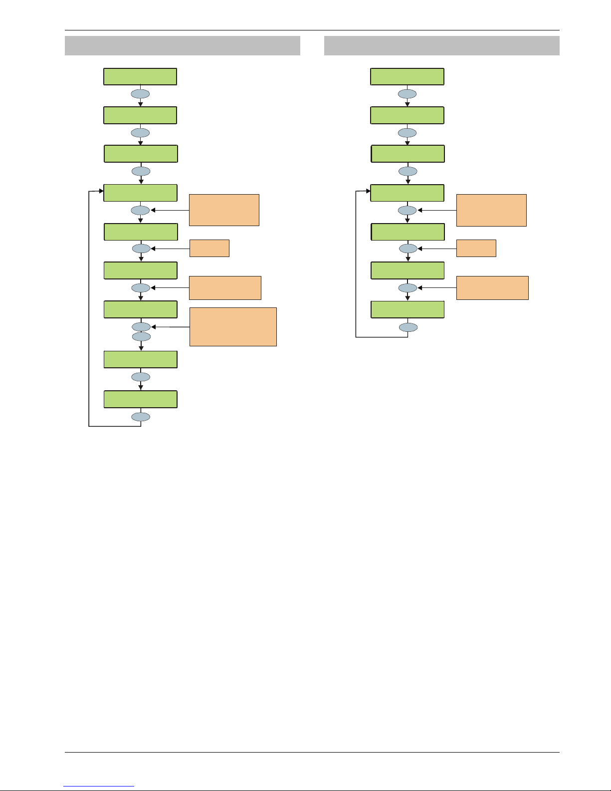
Premier 640 Installation Manual Programming the Control Panel
INS344 55
PC Output Text
>73!:0!3$-$6:Z[
V-0E(-!HO:508<
Yes
Yes
9
wxyz
V-0E(-!HO:508<
I,!H#:O#:!"$P:
!
I,!H#:O#:!+!"$P:
No
h7D5:!"$P:!!W.N,
Use keys 1 - 8 to select
a text option or use the
SCROLL key to search
i.e. 4 = PC Output 4 Text
4
ghi
No
,$8:)(-!e$(:589
!
7D5:!"$P:!!h.Nh
Use keys 0 - 9 to program
text the same way that a
mobile phone works
Press NO to
edit the text
V-0E(-!HO:508<
3=<:$/!"5/$)<
!
I,!H#:O#:!g!"$P:
Press NO followed by YES
to clear the screen or keep
pressing NO to change between
upper ca se, lower case,
numerical and predictive text
Yes
????
????
!
!
7D5:!"$P:!!W,?;
Yes
,$8:)(-!e$(:589
!
7D5:!"$P:!!W+*h
Text may be assigned to PC Control Outputs 1 to 8 to allow
the user to select the correct Output by description instead of
number. A maximum of 16 characters can be programmed
for each of the PC Outputs.
Text is programmed in a similar way to mobile phones.
Select characters by pressing the corresponding key the
appropriate number of times (to select a character on the
same key, press
%
to move the cursor along).
Custom O/P Text
>73!:0!3$-$6:Z[
V-0E(-!HO:508<
Yes
Yes
9
wxyz
V-0E(-!HO:508<
,#<:0/!H]I!"$P:
!
,#<:
0/!
H]I+!"$P:
No
h7D5:!"$P:!!W.N,
Use keys 1 - 4 to select
a text option or use the
SCROLL key to search
i.e. 3 = Custom O/P 3 Text
3
def
,
0//i<!.6:54$
7D5:!"$P:!!h.Nh
Use keys 0 - 9 to program
text the same way that a
mobile phone works
Press NO to
edit the text
V-0E(-!HO:508<
3=<:$/!"5/$)<
!
,#<:0/!H]If!"$P:
Yes
????
Text may be assigned to Custom Outputs 1 to 4 to allow
indication on the keypads display when the output is active
(see page 66 for details).
!
Outputs 1 & 2 are silent and outputs 3 & 4 give an
audible warning every 30 seconds for 3 minutes or until
a code is entered or RESET is pressed.
Text is programmed in a similar way to mobile phones.
Select characters by pressing the corresponding key the
appropriate number of times (to select a character on the
same key, press
%
to move the cursor along).
Page 56
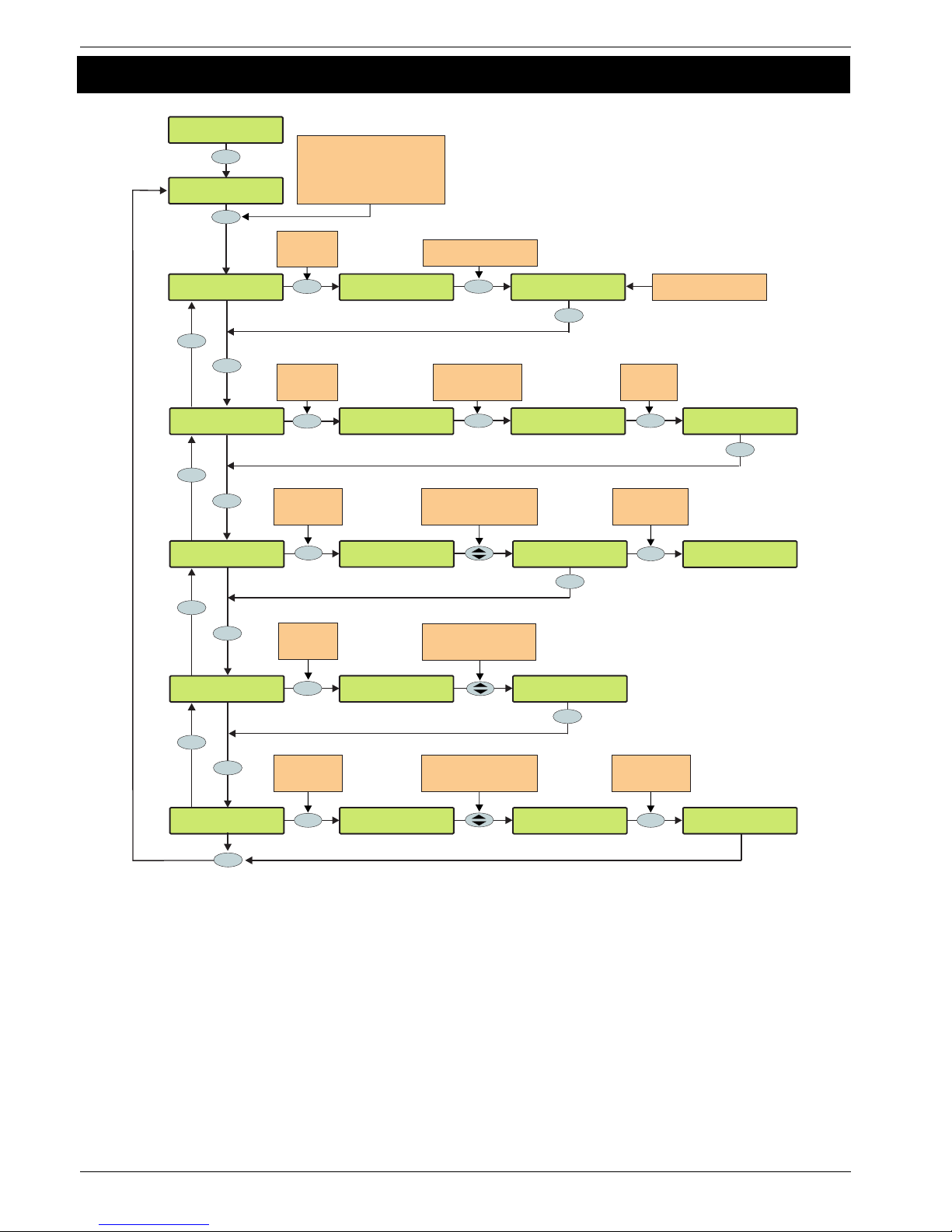
Programming the Control Panel Premier 640 Installation Manual
56 INS344
5.4 Keypad Setup
YES to Select:Keypad Setup
RKP*2,3 Options:
* * * T * * * *
RKP*1,1 Areas:
* * All Areas *
RKP*2,3 Mapping
Z1- 000, Z2- 000
Yes
No
??
Yes
Yes
No
Yes
Yes
Yes
Yes
No
Use keys 1 - 8 to select a
keypad and press 0 to
toggle between networks e.g.
0, 3 = Network 2, Keypad 3
(a * to the left of the device number
indicates that the device is fitted)
RKP*2,3 Areas:
* * All Areas *
Uses Profile 80<
* * All Areas *
Uses Profile 64<
* * Area 64 * *
RKP*2,3 Mapping
Z1->000, Z2- 000
Enter a zone number
or press YES
to move to zone B
RKP*2,3 Mapping
Z1- 000, Z2->000
Enter a zone
number
e.g. 011
RKP*2,3 Mapping
Z1- 000, Z2->011
Yes
PA Disabled
>* * * T * * * *
PA is Silent
* * * T>* * * *
RKP*2,3 Volume:
Level = 4
RKP*2,3 Volume:
Level =>4
RKP*2,3 Volume:
Level =>5
Use the SCROLL key
to adjust the volume level
up & down or enter a value
Press NO
to map the
keypad zones
Press NO
to edit the
volume level
Press NO
to edit the
keypad areas
??
RKP*2,3
F A F S E X C *
Sounds:
Yes
Yes
Enter Profile Number
ie 64=Profile64
???
Press No
to edit the
sounder options
Entry Tones
F A F S>E X C *
Fire Tones
>F A F S E X C *
Entry Tones
F A F S>* X C *
No No
Press No
to edit the
keypad options
PA is Silent
* * * T>S * * *
No No
Press No to
select/deselect
the keypad option
Use keys 1 - 8 to select
a sounder option or use the
SCROLL key to search
Use keys 1 - 8 to select
a keypad option or use the
SCROLL key to search
Press No to
select/deselect
the sounder option
Reset
Reset
Reset
Reset
Yes
Top Line = Profile Number
Bottom Line = Profile Text
Page 57

Premier 640 Installation Manual Programming the Control Panel
INS344 57
Keypad Areas
Keypads are assigned to areas via area profiles. A keypad is
assigned to all areas associated with its assigned area profile.
Assigning areas to a keypad determines:
• Which areas the sounder and speaker output in the
keypad will generate tones for i.e. if the keypad is assigned
to areas A and C, the sounder/speaker will only operate
when areas A or C are in alarm, entry, exit etc.
• Which areas can be armed or disarmed from that
keypad when using codes that have the ‘Local Arming’ or
‘Local Disarming’ attributes (see page 87 for details)
• Which areas will cause a Tamper alarm when the keypad
cover is removed
Keypad Zone Mapping
The zones in the keypad need to be mapped to a valid zone
number (1 to 640) before they can be used as part of the
system i.e. Keypad 1 Zone 1 could be mapped to Zone 5
(panel) and Zone 2 could be mapped to Zone 25 (expander
3) etc.
!
Until mapped, the zones in the keypads will not work.
A keypad zone can be mapped to any zone number on
the system, however, when mapped to a zone number
that already exists i.e. Zone 5 (panel), that zone can no
longer be used.
If a zone is mapped to a zone number not already on
the system i.e. Zone 25 (expander 3) and expander 3 is
then added, that zone on the expander (Zone 25)
cannot be used. If you wish to use the zone on the
expander, the keypad zone must be remapped to a
different number.
If a zone is remapped to a different number, the new
zone number must be treated as a new zone on the
system and therefore needs to be programmed
accordingly (the zone programming will NOT
automatically follow the mapping).
Keypad Options
These 8 options control various keypad functions:
Select options by pressing keys 1 to 8 (a letter on the display
means the option is selected, a Dot on the display means the
option is not selected).
P - PA Enabled
Pressing keys 1 & 3 together will cause a PA alarm.
F - Fire Enabled
Pressing keys 4 & 6 together will cause a Fire alarm.
M - Medical Enabled
Pressing keys 7 & 9 together will cause a Medical alarm.
T - Tamper Enabled
Removing the keypad cover will cause a Tamper alarm.
A - PA is Audible
A keypad PA (1 & 3) will cause an audible PA alarm.
D - PA is Delayed
When the keypad PA buttons (1 & 3) are pressed, the
‘Keypad PA Delay’ timer starts, if a User code is entered
before the timer expires, no PA alarm will occur. If a User
code is not entered before the timer expires, a PA alarm will
occur (see page 48 for details).
Q - Quick Arm is Enabled
Pressing the Area or Part keys will Arm or Part Arm the areas
that the keypad is assigned to without the need to enter a
User code first.
O - Info.LED> Output
The ‘Info.’ LED on the keypad comes on when the keypad
output activates and goes off when the keypad output
deactivates.
Keypad Speaker Volume
This option controls the volume level of advisory tones from
loudspeakers connected to the keypads. Advisory tones
consist of ‘Entry/Exit’ and ‘Warning’ type tones. 1 =
minimum; 8 = maximum.
!
Alarm tones are always full volume.
Keypad Sounder Options
The sounder and speaker output in the keypad can be
programmed so that certain types of tones are not generated.
When deselected, Fire, Alarms, Fault, Service, Entry, Exit and
Chime tones will not be heard.
Select tones by pressing keys 1 to 8 (a letter on the display
means the tone is selected, a Dot on the display means the
tone is not selected).
F - Fire Tones On
Fire alarm tones will be generated by the keypad
sounder/speaker.
A - Alarm Tones On
Intruder alarm, Tamper alarm and PA alarm tones will be
generated by the keypad sounder/speaker.
F - Fault Tones On
Fault tones will be generated by the keypad
sounder/speaker.
S - Service Tone On
Service and Warning tones will be generated by the keypad
sounder/speaker.
E - Entry Tones On
Entry tones will be generated by the keypad
sounder/speaker.
X - Exit Tones On
Exit tones will be generated by the keypad sounder/speaker.
C - Chime Tones On
Chime 1, 2 and 3 tones will be generated by the keypad
sounder/speaker.
K - Use Keypad Areas
When selected, the keypad sounder and arming control is
determined by the area that the keypad is assigned to.
When deselected, the keypad becomes an ‘Area Arm Suite’
controller (see page 40 for details). This allows different
combinations of areas to be armed or disarmed depending on
which keypad is used and operates as follows:
• Keypad 1 = Area Arm Suite 1, Keypad 2 = Area Arm
Suite 2, Keypad 3 = Area Arm Suite 3 etc.
• When a User code is entered at a keypad, one of the ‘Area
Arm Suites’ is selected (depending on which keypad was
used) and the areas contained within that suite arm using
the arming mode for that suite, the keypad sounder will also
follow the areas defined by the suite.
Page 58
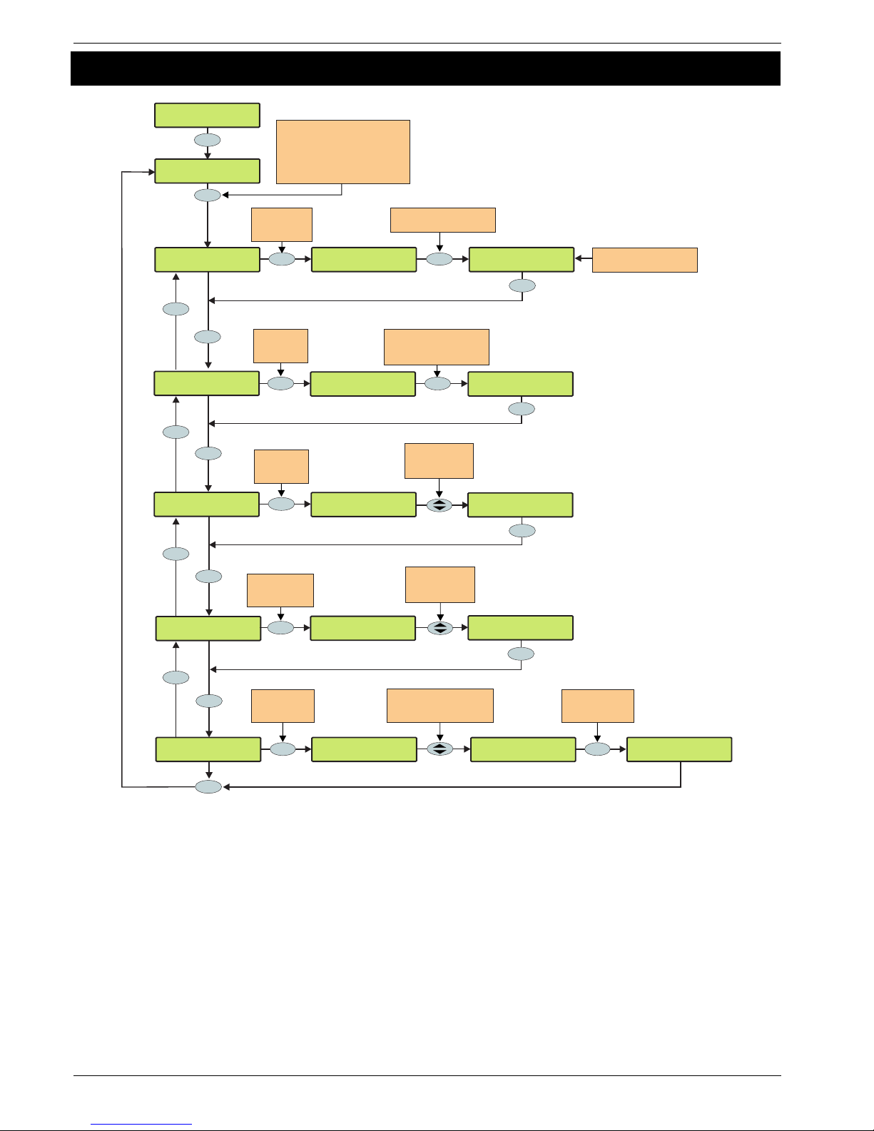
Programming the Control Panel Premier 640 Installation Manual
58 INS344
5.5 Expander Setup
YES to Select:Expander Setup
^Edit Text >ABC
Use the keypad to program
text the same way that a
mobile phone works
In Reception
Edit Text ^>ABC
Exp.*1,1 Areas:
* * All Areas *
Exp. >Aux I/P
Not Used
*2,3
Yes
No
??
Yes
Yes
Yes
Yes
Yes
No
Use keys 1 - 8 to select an
expander and press 0 to
toggle between networks e.g.
0 , 3 = Network 2, Expander 3
(a * to the left of the device number
indicates that the device is fitted)
Exp.*2,3 Areas:
* * All Areas *
Uses Profile 80<
* * All Areas *
Uses Profile 64<
* * Area 64 * *
Exp. >Aux I/P
Auxiliary Tamper
*2,3
Use the SCROLL
key to select
an input type
Exp. Volume:
Volume = 4
*2,3
Exp. Text:*2,3
????
Press NO to
edit the
expander text
Press NO
to edit the
expander areas
??
Use the SCROLL
key to adjust
the volume level
Exp. Volume:
Volume =>5
*2,3
No
Press NO to
edit the
Auxiliary Input
Exp. >Aux I/P
Not Used
*2,3
Yes
No
Press NO to edit
the expander
Volume level
Yes
Exp. Volume:
Volume =>4
*2,3
Exp.
F A F S E X C
Sounds:*2,3
Yes
Press No
to edit the
sounder options
Entry Tones
F A F S>E X C
Fire Tones
>F A F S E X C
Entry Tones
F A F S>* X C
No No
Press No to
select/deselect the
sounder option
Use keys 1 - 8 to select
a sounder option or use the
SCROLL key to search
Yes
Reset
Reset
Reset
Reset
Enter Profile Number
ie 64=Profile 64
Top Line = Profile Number
Bottom Line = Profile Text
Page 59

Premier 640 Installation Manual Programming the Control Panel
INS344 59
Expander Areas
Expanders are assigned to areas via area profiles. An
expander is assigned to all areas associated with its assigned
area profile. Assigning areas to an expander determines:
• Which areas the speaker output on the expander will
generate tones for i.e. if the expander is assigned to
areas A and C, the speaker will only operate when areas
A or C are in alarm, entry, exit etc.
• Which areas will cause a Tamper alarm when the
expander cover is removed
Expander Location Text
Each expander can be assigned up to 16 characters of text.
This text can be used to describe where the expander is
located within the building.
Text is programmed in a similar way to mobile phones. Select
characters by pressing the corresponding key the
appropriate number of times (to select a character on the
same key, press the
%
key to move the cursor along).
Expander Auxiliary Input
Each expander has an input that can be programmed for one
of the following options. If not being used, the input must be
programmed as ‘Not Used’ (Default = Not Used).
Not Used
Never monitored by the system.
Auxiliary Tamper
Normally used for monitoring the box tamper of auxiliary
devices such as power supplies etc (remove 0V for Tamper
alarm).
Bell Tamper
Normally used for monitoring Bell Tamper returns (remove 0V
for Tamper alarm).
Remote Reset
Normally used to reset the system/area following an Intruder
alarm (the area must also be programmed for Anti-code
reset) see page 43 for details (apply 0V to reset).
Line Fault +ve
Normally used to indicate a telephone line fault (remove 0V
for Line Fault).
Line Fault -ve
Normally used to indicate a telephone line fault (apply 0V for
Line Fault).
Silence Sounders
Normally used to silence the Internal sounders following an
Intruder alarm and would be used in conjunction with Audio
Verification units (apply 0V to silence).
Global Omit Key
Normally wired to a key switch. When the key switch is activated,
all zones (with the ‘Omit’ attribute) assigned to the same area as
the expander, will be omitted (apply 0V for omit).
Local Omit Key
Normally wired to a key switch. When the key switch is
activated, all zones (with the ‘Omit’ attribute) wired to the
expander, will be omitted (apply 0V for omit).
PSU Monitor
Normally used to monitor a Power Supply for faults, see page
24 for wiring details.
Defer Auto Arming
Normally used to defer the automatic arming of an area
(apply 0V to defer).
Expander Speaker Volume
This option controls the volume level of advisory tones from
loudspeakers connected to the expanders. Advisory
tones consist of ‘Entry/Exit’ and ‘Warning’ type tones.
1 = minimum; 8 = maximum.
!
Alarm tones are always full volume.
Expander Sounder Options
The speaker output on the expander can be programmed so
that certain types of tones are not generated. When
deselected, Fire, Alarms, Fault, Service, Entry, Exit and
Chime tones will not be heard.
Select tones by pressing keys 1 to 8 (a letter on the display
means the tone is selected, a Dot on the display means the
tone is not selected).
F - Fire Tones On
Fire alarm tones will be generated by the expander
sounder/speaker.
A - Alarm Tones On
Intruder alarm, Tamper alarm and PA alarm tones will be
generated by the expander speaker.
F - Fault Tones On
Fault tones will be generated by the expander speaker.
S - Service Tone On
Service and Warning tones will be generated by the expander
speaker.
E - Entry Tones On
Entry tones will be generated by the expander speaker.
X - Exit Tones On
Exit tones will be generated by the expander speaker.
C - Chime Tones On
Chime 1, 2 and 3 tones will be generated by the expander
speaker.
Page 60
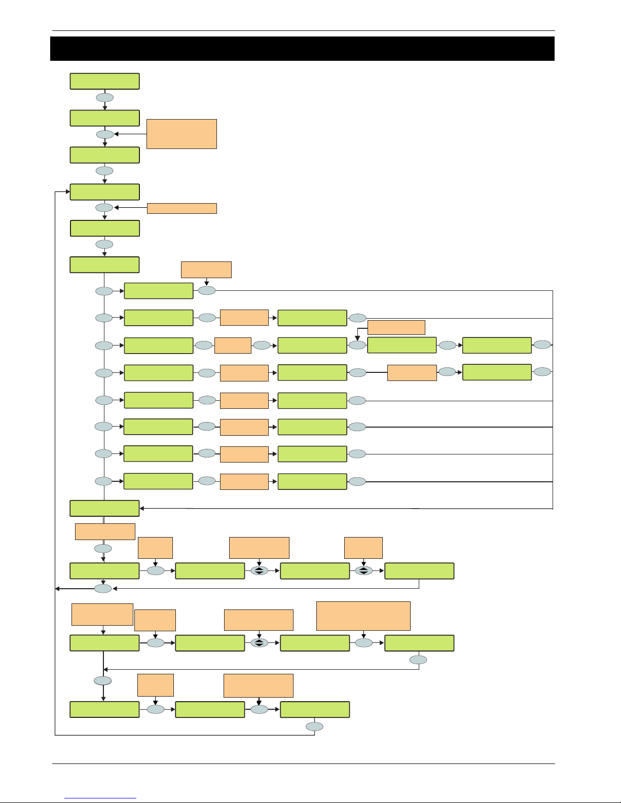
Programming the Control Panel Premier 640 Installation Manual
60 INS344
5.6 System Outputs
YES to Select:System Outputs
System Outputs
Panel Outputs
Yes
Use keys 1 - 8 to select an
output type or use the
SCROLL key to search
e.g. 1 = Digi Outputs
1
Yes
System Outputs
Digi Outputs
Digi Output 1
Not Used (off)
Use keys 1 - 8 to select
an attribute or use the
SCROLL key to search
Digi Output 3
Not Used (off)
User Test
>* * * * * * * *
No
Inverted
*>* * * * * * *
Digi Output 3
> Not Used
Digi Output 3
> Not Used
Digi Output
> System Type
Digi Output 3
> Area Type
Yes
Yes
Yes
Yes
Yes
System output>13
System Open
Area:06>All Areas
24Hr Silent
Digi Output 3
24Hr Silent
Digi Output 3
> Zone Type
Digi Output 3
> User Type
Digi Output 3
> Control Timer
Digi Output 3
> PC Control
Yes
Yes
Yes
Yes
Digi Output 3
PC 4<Control
Digi Output 3
TimerControl 7<
Digi Output 3
Code Entered016<
Yes
Yes
Yes
Yes
Digi Output 3
Zone011<Mimic
Yes
Digi Output 3
Zone011>alarm
No
Enter Output
Type e.g. 13
Enter Output
Type e.g. 06
Enter Zone
Number e.g. 011
Enter User Code
Number e.g. 016
Enter Timer
Number e.g. 7
Enter PC Control
Number e.g. 4
Enter Zone Type
e.g. 2 (alarm)
??
0 _
2
abc
1
6
mno
5
jkl
4
ghi
3
def
Press YES to edit
the selected option
Press NO to
edit the
attributes
3
def
Digi Output 3
> Door Control
Yes
Digi Output 3
Door Control>1,4
Yes
Enter Door Control
Number e.g. 4
7
pqrs
Digi Output 3
System Open
Digi O/P 3 Att:
* * * * * * * *
Yes
Press No to
select/deselect
the attribute
Inverted
*>I * * * * * *
To Program the Output
Attributes (if Required)
Use keys 0 - 9 to select
a House Number or use the
SCROLL key to search
X-10 Output 3
House >A Unit 01
No
X-10 Output 3
House >F Unit 01
Press NO to
edit the House
& Unit Numbers
X-10 Output 3
House A Unit 01
Press YES to Accept and move to
the Unit Number, Then use keys 0 - 9
to select a House Number or use the
SCROLL key to search
Yes
X-10 Output 3
House F Unit>14
If X-10 Outputs are
being programmed
(System outputs option7)
Yes
No
Yes
^Edit Text >ABC
Use the keypad to program
text the same way that a
mobile phone works
Yes
X-10 Output 3
????
Press NO to
edit the
expander text
Yes
In Reception
Edit Text ^>ABC
Yes
Enter Output Number e.g. 3
Area:06>Area 64
* * Area 64 * *
Enter Profile number
ie 64 = Profile 64
Yes
Yes
Yes
Page 61

Premier 640 Installation Manual Programming the Control Panel
INS344 61
Available Outputs
Various sets of programmable outputs can be found on the
control panel, keypads, expanders and output modules.
Panel Outputs
Panel outputs 1 - 5 are located on the top right hand corner
of the control panel and can be programmed to any of the
output types listed (see page 23 for wiring details).
Digi Outputs
Digi outputs 1 - 8 are located on the left hand side of the
control panel and can be programmed to any of the output
types listed (see page 23 for wiring details).
Digi Channels
Digi channels 1 - 8 are for the Com300, Com2400 and
ComISDN plug-on communicators and can be programmed
to any of the output types listed.
RedCARE/Relay Pins
RedCARE or Relay Pins 1 - 8 are for a plug on RedCARE or
RM8 Relay module and can be programmed to any of the
output types listed.
Keypad Outputs
Keypad outputs are for the outputs on the remote keypads
(see page 15 for details) and can be programmed to any of
the output types listed. Wire as per Panel Outputs shown on
page 23.
Expander Outputs
Expander outputs are for the outputs on the zone/output
expanders (see page 16 for details) and can be programmed
to any of the output types listed. Wire as per Panel Outputs
shown on page 23.
Custom Outputs
Custom outputs are NOT physical outputs they are ‘Software’
outputs that can be configured to operate under certain
conditions (see page 66 for details). Once configured these
outputs can then be assigned to a physical output (see
system outputs 22-27).
X-10 Outputs
X-10 outputs are NOT physical outputs they are ‘Software’
outputs that can be configured to operate devices that are
connected to an X-10 controller. These outputs can also be
assigned a house and unit number along with descriptive
text. (see page 66 for details).
Programming Outputs
When programming outputs, select an output group and an
output type from that group’s list (each output group has its
own output types) then select attributes (if required).
!
Output Group + Output Type + Output Attributes
= Output Programmed.
Output Group - Not Used
Only the following output type is available:
Not Used (off)
This output type never activates.
Output Group - System
Select an output type from the following options:
00 - ATS Path Fault
This output type activates when a fault is detected with the Alarm
Transmission System and deactivates when the fault is cleared.
01 - Mains Power Off
This output type activates when no AC Mains is detected on
the control panel and deactivates when mains is detected.
02 - Aux Fuse Blown
This output type activates when the Auxiliary fuse (F1) fails
and deactivates when the system is reset.
03 - Bell Tamper
This output type activates when the control panel Bell tamper
or an expander input (programmed as Bell tamper) is
activated, causing a Tamper alarm on the system, and
deactivates when the Tamper alarm is reset.
04 - Auxiliary Tamper
This output type activates when the control panel Aux tamper
or an expander input (programmed as Auxiliary tamper) is
activated, causing a Tamper alarm on the system, and
deactivates when the Tamper alarm is reset.
05 - Panel Lid Tamper
This output type activates whenever the panel cover is
removed, causing a Tamper alarm on the system, and
deactivates when the Tamper alarm is reset.
06 - Engineer Working
This output type activates whenever an Engineer code is
entered to access the programming menu and deactivates
when the engineer logs off.
07 - Confirm Devices
This output type activates when the control panel requires
devices to be confirmed and deactivates when the devices
are confirmed (see page 96 for details).
08 - Service Required
This output type activates when the ‘Service Interval’ timer
expires and deactivates when an Engineer code is entered
(see page 47 for details).
09 - Bell Fuse Blown
This output type activates when the control panel bell fuse
(F4) fails and deactivates when the system is reset.
10 - Battery Fault
This output type activates when the system detects a fault with
the stand-by battery, and deactivates when the fault clears.
11 - Battery Test On
This output type activates when the ‘Battery Test’ starts, and
deactivates when the test expires (see page 47 for details).
12 - Courtesy Light
This output type activates when the ‘Courtesy’ timer starts, and
deactivates when the timer expires (see page 47 for details).
13 - System Open
This output type activates when all areas are unarmed, and
deactivates when any area is armed.
14 - Fully Arm
This output type activates when the system is fully armed and
deactivates when the system is disarmed.
15 - Digi Failed
This output type activates when the plug-on communicator fails
to report to the Alarm Receiving Centre (after 3 dialling
attempts), and deactivates the next time the communicator
successfully reports to the Alarm Receiving Centre.
Page 62

Programming the Control Panel Premier 640 Installation Manual
62 INS344
16 - Digi Successful
This output type activates when the plug-on communicator
successfully reports to the Alarm Receiving Centre and
deactivates the next time the communicator is triggered.
17 - Digi Active
This output type activates when the plug-on communicator is
triggered and deactivates when the communicator shuts down.
18 - UDL Lockout
This output type activates when an attempt is made to
upload/download with incorrect site details more than three times
and deactivates after 4 hours or after a valid User code is entered.
19 - UDL Call Active
This output type activates when an upload/download is started
and deactivates when the upload/download finishes.
20 - UDL Enabled
This output type activates when ‘Enable UDL/Engineer’ is
enabled and deactivates when ‘Enable UDL/Engineer’ is
disabled .
21 - Confirmed Alarm
If the system is already in alarm, this output type activates
when a different zone (not on the entry route) is activated and
deactivates at the end of the ‘Confirmation’ time, when a code
is entered within the ‘Abort’ time or when the alarm is reset.
22 - Custom1 Stage A
This output type operates when ‘Custom Output 1’ Stage A
activates and deactivates when ‘Custom Output 1’ Stage A
deactivates.
23 - Custom1 Stage B
This output type operates when ‘Custom Output 1’ Stage B
activates and deactivates when ‘Custom Output 1’ Stage B
deactivates.
24 - Custom1 Stage AB
This output type operates when ‘Custom Output 1’ Stage A or
B activates and deactivates when ‘Custom Output 1’ Stage A
deactivates.
25 - Custom2 Stage A
This output type operates when ‘Custom Output 2’ Stage A
activates and deactivates when ‘Custom Output 2’ Stage A
deactivates.
26 - Custom2 Stage B
This output type operates when ‘Custom Output 2’ Stage B
activates and deactivates when ‘Custom Output 2’ Stage B
deactivates.
27 - Custom2 Stage AB
This output type operates when ‘Custom Output 2’ Stage A or
B activates and deactivates when ‘Custom Output 2’ Stage A
deactivates.
28 - Radio-Pad Failed
This output type activates when the radio pad fails to
communicate with the Alarm Receiving Centre and
deactivates when the radio pad successfully communicates.
29 - Radio Successful
This output type activates when the radio pad successfully
communicates with the Alarm Receiving Centre and deactivates
when the radio pad fails to successfully communicate.
30 - No Radio Signal
This output type activates when the Radio-Pads forward signal is
lost and deactivates when the signal is regained.
31 - Radio-Pad Lost
This output type activates when the Radio-Pad stops
communicating with its base station or the control panel and
deactivates when communication starts again.
32 – Custom3 Stage A
This output type operates when ‘Custom Output 3’ Stage A
activates and deactivates when ‘Custom Output 3’ Stage A
deactivates.
33 - Custom3 Stage B
This output type operates when ‘Custom Output 3’ Stage B
activates and deactivates when ‘Custom Output 3’ Stage B
deactivates.
34 - Custom3 Stage AB
This output type operates when ‘Custom Output 3’ Stage A or
B activates and deactivates when ‘Custom Output 3’ Stage A
deactivates.
35 - Custom4 Stage A
This output type operates when ‘Custom Output 4’ Stage A
activates and deactivates when ‘Custom Output 4’ Stage A
deactivates.
36 - Custom4 Stage B
This output type operates when ‘Custom Output 4’ Stage B
activates and deactivates when ‘Custom Output 4’ Stage B
deactivates.
37 - Custom4 Stage AB
This output type operates when ‘Custom Output 4’ Stage A or
B activates and deactivates when ‘Custom Output 4’ Stage A
deactivates.
38 - Com 1 Fault
This output type activates when whatever is connected to
Com Port 1 stops communicating with the control panel and
deactivates when communication starts again.
39 - Com 2 Fault
This output type activates when whatever is connected to
Com Port 2 stops communicating with the control panel and
deactivates when communication starts again.
40 - Com 3 Fault
This output type activates when whatever is connected to
Com Port 3 stops communicating with the control panel and
deactivates when communication starts again.
41 - Com 1 No Signal
This output type activates when whatever is connected to
Com Port 1 loses its signal and deactivates when its signal is
regained.
42 - Com 2 No Signal
This output type activates when whatever is connected to
Com Port 2 loses its signal and deactivates when its signal is
regained.
43 - Com 3 No Signal
This output type activates when whatever is connected to
Com Port 3 loses its signal and deactivates when its signal is
regained.
44 - Coms Fault
This output type activates whenever any type of
communication fault occurs i.e. No Signal, Com Port Fault, line
fault etc. and deactivates when communication starts again.
45 - Radio Jamming
This output type activates whenever the wireless radio
receiver detects a jamming signal and deactivates when the
jamming signal is removed.
46 - Radio RX Tamper
This output type activates when the wireless radio receiver lid
is removed, causing a Tamper alarm on the system, and
deactivates when the Tamper alarm is reset.
Page 63

Premier 640 Installation Manual Programming the Control Panel
INS344 63
47 - Detector Test
This output type is activated via remote maintenance software
to initiate a diagnostics check on a PD6662: 2004/EN 50131-1
Grade 3 detector and deactivates after 10 seconds.
48 - ATS Remote Test
This output type conforms to the BSIA Form 175 Specification.
When a Line Fault is not present it can be activated remotely by
Wintex, or by using the ‘Test Call Timer’ or ‘Start Test Call’ option
on the control panel to initiate a test on ATE equipment that have
an ATS test input. NOTE: Only the RedCare Line Fault and
Control panel Line Fault inputs can be used with the output type.
49 - No ATS Available
This output type activates when no Alarm Transmission paths
are available and deactivates when the fault is cleared.
50 - CIE Fault
This output type activates when a fault occurs on the CIE and
deactivates when the fault is cleared.
51 - PSU Fuse Blown
This output type activates when the Auxiliary input type ‘PSU
Monitor’ detects a 12V failure and deactivates when the fault
is reset.
52 - PSU Battery Flt
This output type activates when the Auxiliary input type ‘PSU
Monitor’ detects a battery fault and deactivates when the fault
is reset.
53 – WD Test Active
This output is activated via remote maintenance software to
initiate a diagnostics check on an external sounder with
remote test capability and will deactivate after 1 minute.
Output Group - Area
Any Area Profile can be assigned to each output type. All
areas assigned to the area Profile will activate the output.
Select an output type from the following options:
00 - Alarm
This output type activates when any type of Intruder alarm occurs in
the selected area, and deactivates when the Intruder alarm is reset.
01 - Guard Alarm
This output type activates when a zone programmed as
‘Guard’ causes an Intruder alarm in the selected area and
deactivates when the alarm is reset.
02 - Guard Access Alarm
This output type activates when a zone programmed as
‘Guard Access’ causes an Intruder alarm in the selected area
and deactivates when the alarm is reset.
03 - Entry Alarm
This output type activates when a zone programmed as
‘Entry/Exit 1 or 2’ causes an Intruder alarm in the selected
area and deactivates when the alarm is reset.
04 - Confirmed Alarm
If an area is already in alarm, this output type activates when a
different zone (not on the entry route) is activated in the selected
area and deactivates at the end of the ‘Confirmation’ time, when a
code is entered within the ‘Abort’ time or when the alarm is reset.
05 - 24Hr Audible
This output type activates when a zone programmed as ‘24Hr
Audible’ causes an Internal alarm or Intruder alarm in the
selected area and deactivates when the alarm is reset.
06 - 24Hr Silent
This output type activates when a zone programmed as ‘24Hr
Silent’ causes a silent alarm or Intruder alarm in the selected
area and deactivates when the alarm is reset.
07 - 24Hr Gas
This output type activates when a zone programmed as ‘24Hr
Gas’ causes a Silent alarm or Intruder alarm in the selected
area and deactivates when the alarm is reset.
08 - PA Alarm
This output type activates when any type of ‘PA alarm’ i.e. PA
audible, PA silent or Duress causes a PA alarm in the
selected area and deactivates when the alarm is reset.
09 - PA Silent
This output type activates when a zone programmed as ‘PA
Silent’ or a keypad PA (1 & 3) causes a silent PA alarm in the
selected area and deactivates when the alarm is reset.
10 - Duress
This output type activates when a User code with the ‘Duress’
attribute causes a silent PA alarm in the selected area and
deactivates when the alarm is reset.
11 - Fire Alarm
This output type activates when a zone programmed as ‘Fire’
or a keypad Fire (4 & 6) causes a Fire alarm in the selected
area and deactivates when the alarm is reset.
12 - Medical
This output type activates when a zone programmed as ‘Medical’
or a keypad Medical (7 & 9) causes a Medical alarm in the
selected area and deactivates when the alarm is reset.
13 - Auxiliary Alarm
This output type activates when a zone programmed as
‘Auxiliary’ causes a Silent alarm in the selected area and
deactivates when the alarm is reset.
14 - Tamper Alarm
This output type activates when any type of Tamper alarm
occurs in the selected area and deactivates when the alarm is
reset.
15 - Alarm Abort
If the selected area is in alarm, this output type activates
when a User code is entered to cancel the alarm in the
selected area and deactivates after 10 seconds.
16 - Ready
This output type activates when all zones in the selected area
are secure and deactivates when any zone in the selected
area is activated.
17 - Entry Mode
This output type activates when the selected area is in the entry
mode and deactivates when the area is not in the entry mode.
18 - 2
nd
Entry Mode
This output type activates when the 2nd entry timer for the
selected area starts and deactivates when the 2
nd
entry timer
expires.
19 - Exit Mode
This output type activates when the selected area is in the exit
mode and deactivates when the area is not in the exit mode.
20 - Entry/Exit Mode
This output type activates when the selected area is in the
entry or exit mode and deactivates when the area is no longer
in the entry or exit mode.
21 - Armed
This output type activates when the selected area is armed
and deactivates when the selected area is disarmed.
22 - Full Armed
This output type activates when the selected area is fully armed
and deactivates when the selected area is disarmed.
Page 64

Programming the Control Panel Premier 640 Installation Manual
64 INS344
23 - Part Armed
This output type activates when the selected area is part armed
and deactivates when the selected area is disarmed.
24 - Part Arming
This output type activates when the selected area is part
arming and deactivates when the selected area arms.
25 - Force Armable
This output type activates when the selected area has at least
one zone with the ‘Force Omit’ attribute, and the area is able
to be force armed. It will deactivate when the area cannot be
force armed.
26 - Force Armed
This output type activates when the selected area is forced to
arm with zones active, and deactivates when the all zones are
reinstated.
27 - Arm Failed
This output type activates when the selected area fails to arm
because a zone is in fault, and deactivates when a valid User
code is entered.
28 - Bell SAB
This output type activates when an External alarm occurs in the
selected area, and deactivates when area is disarmed or the
‘Bell Duration’ timer expires.
29 - Bell SCB
This output type deactivates when an External alarm occurs in
the selected area, and activates when area is disarmed or the
‘Bell Duration’ timer expires.
30 - Strobe
This output type activates when an External alarm (or Arm Fail)
occurs in the selected area, and deactivates when area is
disarmed (or a valid User code is entered).
31 - Detector Latch
This output type activates for 5 seconds when the selected
area is in the exit mode then activates again when the area
arms and deactivates when an Intruder alarm occurs or the
selected area is disarmed.
32 - Detector Reset
This output type is normally active, and deactivates for 5
seconds when the selected area is in the exit mode.
33 - Walk Test Active
This output type activates when the ‘Walk Test’ procedure is
selected, and deactivates when the ‘Walk Test’ procedure is
cancelled.
34 - Zones Omitted
This output type activates when a zone in the selected area
with the ‘Omit’ attribute, is omitted by the user, and
deactivates when the zone is reinstated.
35 - 24Hr Zones Omit
This output type activates when a zone programmed as ‘24Hr
Audible’ or ‘24Hr Silent’ (with the ‘Omit’ attribute) is omitted by
the user, and deactivates when the zone is reinstated.
36 - Reset Required
This output type activates when the selected area requires a
reset following an alarm, and deactivates when the alarm is
reset.
37 - Door Strike
This output type activates for the 4 seconds when a User code
with the ‘Door Strike’ attribute is entered for the selected area.
38 - Chime Mimic
This output type activates for 2 seconds when a zone in the
selected area with the ‘Chime’ attribute is activated.
39 - Chime Enabled
This output type activates when ‘Chime’ is enabled for the
selected area, and deactivates when ‘Chime’ is disabled for
the selected area.
40 - DK First Knock
This output type activates when a zone in the selected area
with the ‘Double Knock’ attribute is activated for the first time,
and deactivates when the zone causes an alarm or the
‘Double Knock Delay’ timer expires.
41 - BP First Knock
This output type activates when a zone in the selected area
with the ‘Beam Pair’ attribute is activated for the first time and
deactivates when another zone with the ‘Beam Pair’ attribute,
causes an alarm or the ‘Beam Pair Time’ expires.
42 - On Test
This output type activates when a zone in the selected area
with the ‘Test’ attribute is placed on test and deactivates when
the ‘Soak Test Time’ expires.
43 - Test Fail
This output type activates when a zone in the selected area with
the ‘Test’ attribute is placed on test (and fails) and deactivates
when an Engineer code is entered or the ‘Soak Test Time’ expires.
44 - Internal Alarm
This output type activates when an Internal alarm occurs in the
selected area, and deactivates when the alarm is cancelled.
45 - Auto Arming
This output type activates when the selected area ‘Auto
Arms’, and deactivates when the selected area is disarmed.
46 - Time Arming
This output type activates for 5 minutes prior to the selected
area being armed using the ‘Control Timers’.
47 - 1st Code Entered
This output type activates for 30 seconds when a User code
with the ‘Dual Code’ attribute is entered for the selected area.
48 - 2nd Code Entered
This output type activates for 30 seconds when two User
codes with the ‘Dual Code’ attribute are entered for the
selected area.
49 - Area Secured
This output type activates whenever a ‘Security Key’ zone
type is used to lock keypads out and deactivates when the
keypads are unlocked again.
50 - Part Armed 1
This output type activates when a Part Arm 1 is selected for
the selected area and deactivates when part arm 1 is
disarmed.
51 - Part Armed 2
This output type activates when a Part Arm 2 is selected for
the selected area and deactivates when part arm 2 is
disarmed.
52 - Part Armed 3
This output type activates when a Part Arm 3 is selected for
the selected area and deactivates when part arm 3 is
disarmed.
53 - Custom Alarm
This output type activates when any ‘Custom’ zone type
causes an alarm in the selected area and deactivates when a
valid user code is entered.
Page 65

Premier 640 Installation Manual Programming the Control Panel
INS344 65
54 - Zone Warning
This output type activates when ‘Custom’ zone type in the
selected area with the ‘Warning Req’ attribute (see page 37 for
details) is activated for the duration of the ‘Warning Delay’
timer (see page 48 for details) and deactivates when the zone
activity is cleared.
55 - Arm Fail Warning
This output type activates when the selected area fails to arm
after a period of time (controlled by the area exit time) when
using ‘Entry/Exit’ or ‘Exit Term.’ arming and deactivates when
the area arms.
56 - Forced Entry
This output type activates for the duration of the ‘Forced
Entry’ timer (see page 48 for details) when any ‘Guard’ or
‘Custom’ zone with the ‘Guard’ attribute is activated (see
page 36 for details),.
57 - Zones Locked Out
This output type activates when any zone is locked out
following an Intruder Alarm activation and deactivates when
all zones are clear and reinstated.
58 - All Areas Armed
This output type activates when all of the selected areas are
armed and deactivates when any one of those areas is
disarmed.
59 - Time Arm Disabled
This output type activates when the timed arming procedure
is disabled (see page 37 for details) and deactivates when
timed arming is reinstated.
60 - Armed/Alarm
This output type activates when the selected area is armed
and deactivates when the selected area is disarmed
This output type also pulses when an Intruder alarm occurs in the
selected area, and deactivates when the selected area is
disarmed.
61 - Intruder Alarm
This output type activates when an Intruder alarm occurs, and
deactivates when the Intruder alarm is cancelled.
!
Tamper alarms will not activate this output.
62 - Speaker Mimic
This output type activates whenever the internal speaker
output is on, and deactivates when the speaker output is off.
63 - Full Armed/Exit
This output type activates when the selected area is in the full arm
exit mode and then arms and deactivates when the area is
disarmed.
64 - Detector Fault
This output type activates when a detector fault occurs and
deactivates when the fault is reset.
65 - Detector Masked
This output type activates when a detector mask occurs and
deactivates when the mask is reset.
66 - Fault Present
This output type activates when a general fault occurs i.e.
Line Fault, AC Mains Fail, Detector Fault etc. and deactivates
when the fault is cleared.
67 - LED Control
This output type is always activate and deactivates when a
User or Engineers code is entered to gain access to a menu.
The output activates again 30 seconds after the
user/engineer exits the menu. This output type is for use with
detectors that require 0V applied to disable their LED’s.
68 - Full Arm Entry
This output type activates when the entry mode is started and
deactivates when the entry mode finishes whenever the
system in Full Armed.
Output Group - Zone
Any zone can be assigned to this output type. Select a zone
number from 1 to 168 then select an output type from the
following options:
Mimic
This output type activates when the selected zone is activated
and deactivates when the zone is secure. This output will
work if the zone is armed or disarmed.
MimicArm
This output type activates when the selected zone is activated
and deactivates when the zone is secured. This output will
only work if the zone is armed.
Alarm
This output type activates when the selected zone causes an
alarm and deactivates when the alarm is reset. This output
will only work if the zone is armed.
Tamper
This output type activates when the selected zone causes a
Tamper alarm and deactivates when the tamper is reset. This
output will work if the zone is armed or disarmed.
MimicLat
This output type activates when the selected zone is activated
and deactivates when the next time the zone is activated. This
output will work if the zone is armed or disarmed.
Omitted
This output type activates when the selected zone is omitted
and deactivates when the zone is reinstated.
Output Group - User Code Entered
Any user can be assigned to this output type. Select a user
number from 1 to 99 ).
This output type activates for 5 seconds when the selected
User code is entered.
Output Group - Control Timer
Select a Control Timer from 1 to 8.
These output types activate when the respective control timer
turns on and deactivate when the timer turns off.
Output Group - PC Control
Select a PC Control from 1 to 8.
These output types can be activated and deactivated using a
PC running the Wintex UDL software.
Output Group - Door Control
Select a Door Control from 1,1 to 8,8.
These output types activate for the duration of the ‘Door
Strike’ timer when a valid User code (assigned to the same
door) is entered and deactivates when the timer expires.
These output types are used in conjunction with the ‘Door
Control’ User option (see page 90 for details).
Page 66
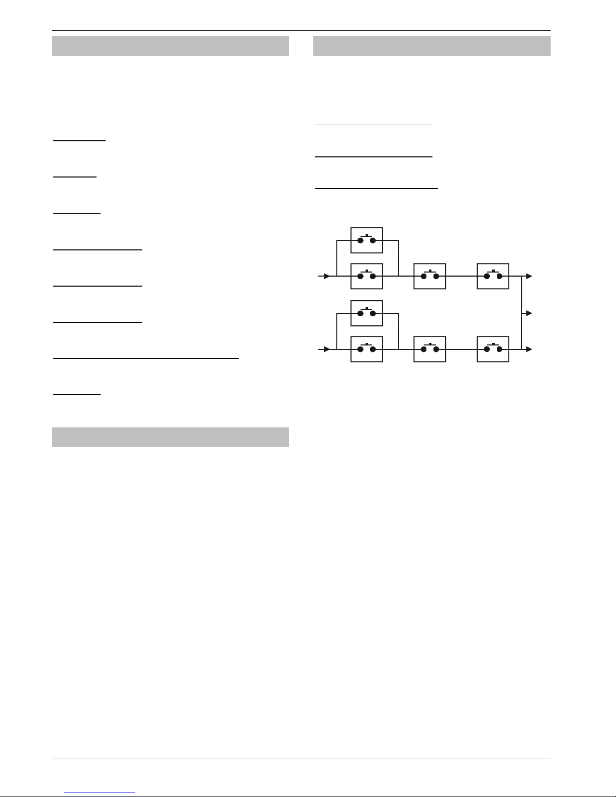
Programming the Control Panel Premier 640 Installation Manual
66 INS344
Output Attributes
Assigning an attribute to an output will alter how the output
works. The following attributes can be assigned to any of the
various types listed.
Select attributes by pressing keys 1 to 8 (a letter on the
display means the attribute is selected, a ‘Dot’ on the display
means the attribute is not selected).
U - User Test
The output will activate when a user performs a User test (see
page 95 for details).
I - Inverted
The output is inverted (an output that applies 0V when active
will become an output that applies 12V when active).
L - Latching
When activated, the output will remain on until a valid User
code is entered.
1 - Use Pulse Period 1
When activated, the output will remain on for the duration of
the ‘Pulse Period 1’ timer (see page 47 for details).
2 - Use Pulse Period 2
When activated, the output will remain on for the duration of
the ‘Pulse Period 2’ timer (see page 47 for details).
3 - Use Pulse Period 3
When activated, the output will remain on for the duration of
the ‘Pulse Period 3’ timer (see page 47 for details).
C - Only Active With Custom Output 1 Stage A
The output will only operate whilst ‘Custom Output Stage A’
is ‘On’ (see page ‘Custom Outputs’ for details).
R - Random
The output will activate randomly. A minimum and maximum
‘On’ time can also be programmed (see page 47 for details).
X-10 Outputs
X-10 Outputs are outputs that can be configured to operate
devices that are connected to an X-10 controller. These
outputs can be assigned a house and unit number.
To Program an output for X-10, proceed as follows:
Program the output type to ensure correct operation when
the programmed condition occurs i.e. an output programmed
as ‘Entry/Exit’ will activate when the selected area is in the
entry or exit mode and deactivate when the area is no longer
in the entry or exit mode.
Assign any attributes i.e. ‘Pulsed 1’ would cause the output to
be timed for the duration of the ‘Pulse 1’ timer.
Assign a House and Unit number i.e. this is the physical
address of the X-10 Unit and ensures that the correct unit in
the correct area operates when the output condition is met i.e
the correct unit switches on and off during Entry/Exit.
Custom Outputs
Custom outputs are NOT physical outputs they are ‘Software
outputs that can be configured to operate under certain
conditions. Once configured these outputs can then be
assigned to a physical output (see system outputs 22-27 and
32-37, page 62 for details).
Custom Output 1 - 4, Stage A
Will activate when switches 1 or 2 and 3 and 4 are active.
Custom Output 1 - 4, Stage B
Will activate when switches 5 or 6 and 7 and 8 are active.
Custom Output 1 - 4, Stage AB
Will activate when switches 1 or 2 and 3 and 4 are active OR
switches 5 or 6 and 7 and 8 are active.
2
1
34
6
5
78
A
B
A
B
Example
Switch 1 is programmed as: Zone 1 Mimic
Switch 2 is programmed as: Zone 2 Mimic
Switch 3 is programmed as: Armed
Switch 4 is programmed as: Never Active (and inverted)
!
Custom Output 1 Stage A will only activate when
switches 1 OR 2 AND 3 AND 4 are closed.
i.e. if ZONE 1 or ZONE 2 ACTIVATES whilst the system
is ARMED (switch 4 is always closed).
Assign up to 16 Characters of text to each unit to allow easy
identification when the output needs to be manually triggered
directly from the keypad using the
,.
command i.e.
‘Entrance Light’.
Page 67
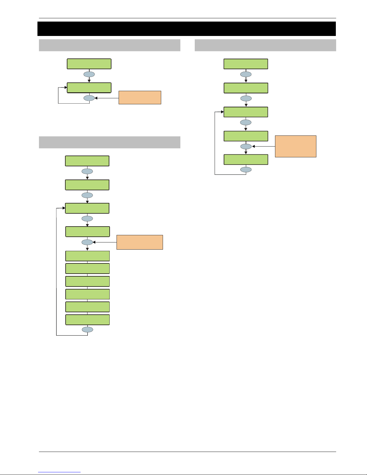
Premier 640 Installation Manual Programming the Control Panel
INS344 67
5.7 UDL/Digi Options
Reset Digi
>73!:0!3$-$6:Z[
\C?]C595!HO:508<
Yes
Yes
Press RESET to reset the
digimodem - a confimation
tone will be heard
\C?]C595!HO:508<
;$<$:!C595
This option should be used whenever a Premier plug-on
communicator is plugged on or removed from the control
panel.
Start Test Call
>73!:0!3$-$6:Z[
\C?]C595!HO:5
08<
Yes
Yes
Press 0 to send a test call
or 1, 2 or 3 to initiate an
upload to a remote computer
\C?]C595!HO:508<
3:():!"$<:!,(--
0 _
1
\C?]C595!HO:508<
;$<$:!C595
C0! %!
+S*!0)!f!!
"$<:!,(--!d!
,(--!I,d
,0/f%%!!5<!_D-$
F(5:!C5(-!"08$
?00G589!+<:!e]3
3$8D589!C(:(
F(5:!C5(-!"
08$
C5(--589!L01!+I
3$8D589!C(:(
F(5:!,-
$()!C$-(=
C5(--589!L01!+I
?00G589!+<:!e]3
Menu
F(5:!,-
$()!C$-(=
,0/f%%!5<!_D-$
When a Premier plug-on communicator has been fitted to the
control panel. This option can be used to send a test call to
the Alarm Receiving Centre or to initiate a remote
Upload/Download call to one of the programmed callback
numbers.
MSN/Pre-Dial No.
>73!:0!3$-$6:Z[
\C?]C595!HO:5
08<
Yes
!
h!!!!!!!!!!!W+*f
Yes
Use keys 0 - 9 to
enter numbers,
Omit = *, Chime = #
Part = 3 second Pause
A
rea = 10 Se cond Pause
Yes
????
Mggj!
!!
h
!!!!!!!!
W+*f
\C?]C595!HO:508<
;$<$:!C595
2
abc
\C?]C595!HO:508<
'3L]I)$[C5(-!L01
When a ComISDN is connected to an extension of an ISDN line
with more than 1 number, the direct dial number should be
programmed in here, this ensures that the ComISDN will only
answer a call when the direct dial number is dialled. This
number can be up to 24 digits.
!
The Use MSN/Pre-Dial option must also be enabled
(see page 71 for details).
When entering the telephone number the following extra keys
can be used:
Page 68
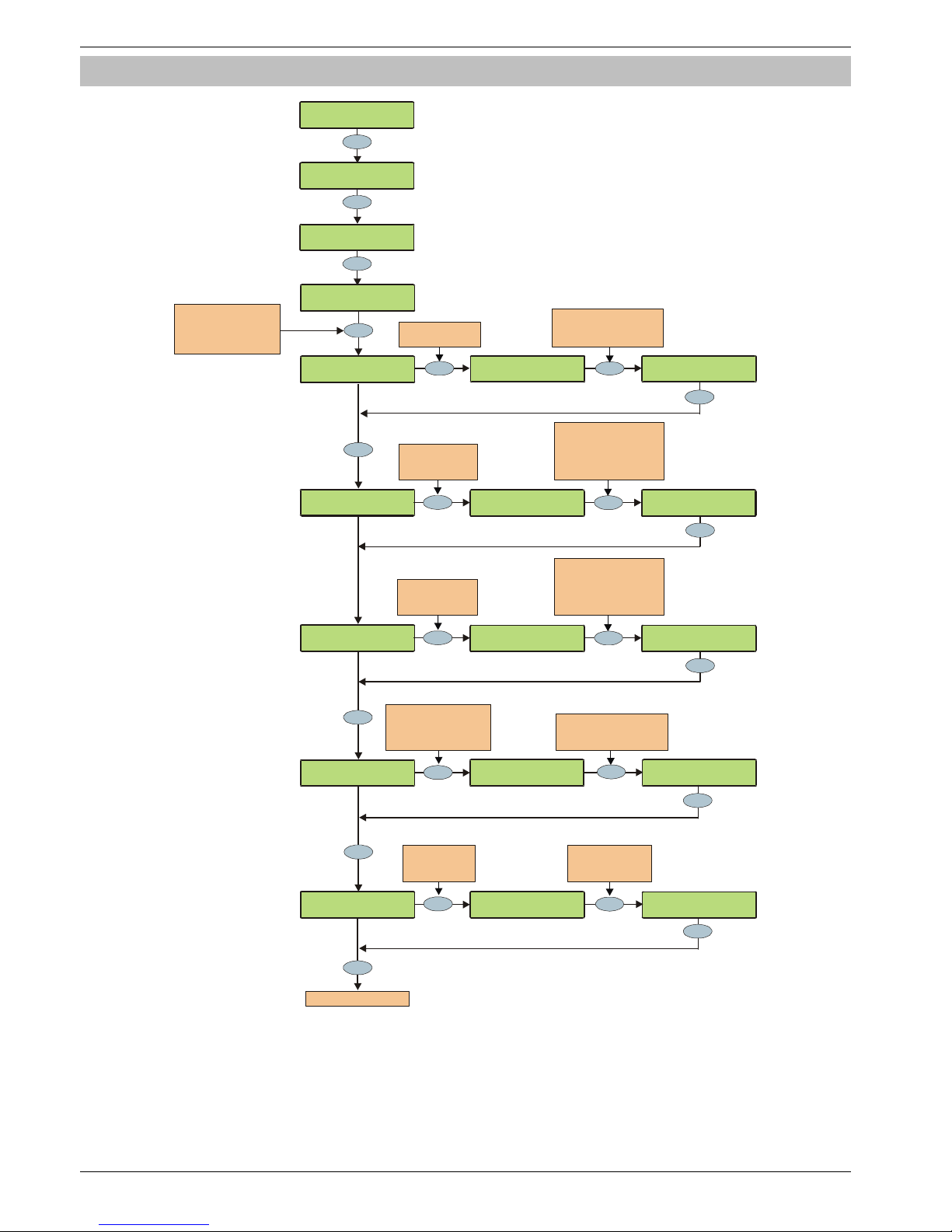
Programming the Control Panel Premier 640 Installation Manual
68 INS344
Program Digi
>73!:0!3$-$6:Z[
\C?]C595!HO:508<
3$608D()=!L01Z
\C?]C595!HO:508<
;$<$:!C595
Yes
2
abc
2
abc
Yes
Yes
No
.;,!+!I)0:060-Z
!!C5<(E-$D
.660#8:!L#/E$)Z
!!!
Press NO to edit the
account numbe r or press
AREA to edit the area
account numbe rs
C5(--589!.::
$/O:<
!!!!!!!!%%
Yes
3
def
Enter the number
of dialling attempts
e.g. 3 = 3 attempts
Yes
3
def
.;,!*!I)0:
060-Z
W!C5<(E-$D
.;,!*!I)0:
060-Z
W!2(<:!20)/(:
No
.;,!*!I)0:060-Z
!!C5<(E-$D
Yes
Yes
h
!!!!!!!!!!!
W+*f
No
????
Press NO to edit
the Secondary
telephone number
Use keys 0 - 9 to enter
the telephone numb er
Omit = *, Chime = #
Part = 3 second Pause
Area = 10 Se con d Pause
cS%Xk%+*fgA&k!
!!!h!!!!!!!!W+*f
????
Use keys 0 - 9 to enter
the account numb er
e.g. 1234 = Account 1234
.660#8:!L#/E$)Z
+*fg
No
Press NO to edit
the number of
dialling attempts
C5(--589!.::
$/O:<
!!!!!!W!%%
C5(--589!.::
$/O:<
!!!!!!W!%f
Yes
Yes
Please refer to next page
Press NO to select
the protocol
Use keys 0 - 4 to
select a protocol or use
the SCROLL key to search
\C?]C595!HO:508<
I)09)(/!C595
Yes
Start
Select the required Alarm
Receiving Centre ‘Set’
e.g. 2 = ‘Set’ 2
!
h!!!!!!!!!!!W+*f
I)5
/()=!L01Z
Yes
h
!!!!!!!!!!!
W+*f
No
????
Press NO to edit
the Primary
telephone number
Use keys 0 - 9 to enter
the telephone numb er
Omit = *, Chime = #
Part = 3 second Pause
Area = 10 Se con d Pause
cS%Xk%+*fgA&k!
!!!h!!!!!!!!W+*f
Page 69
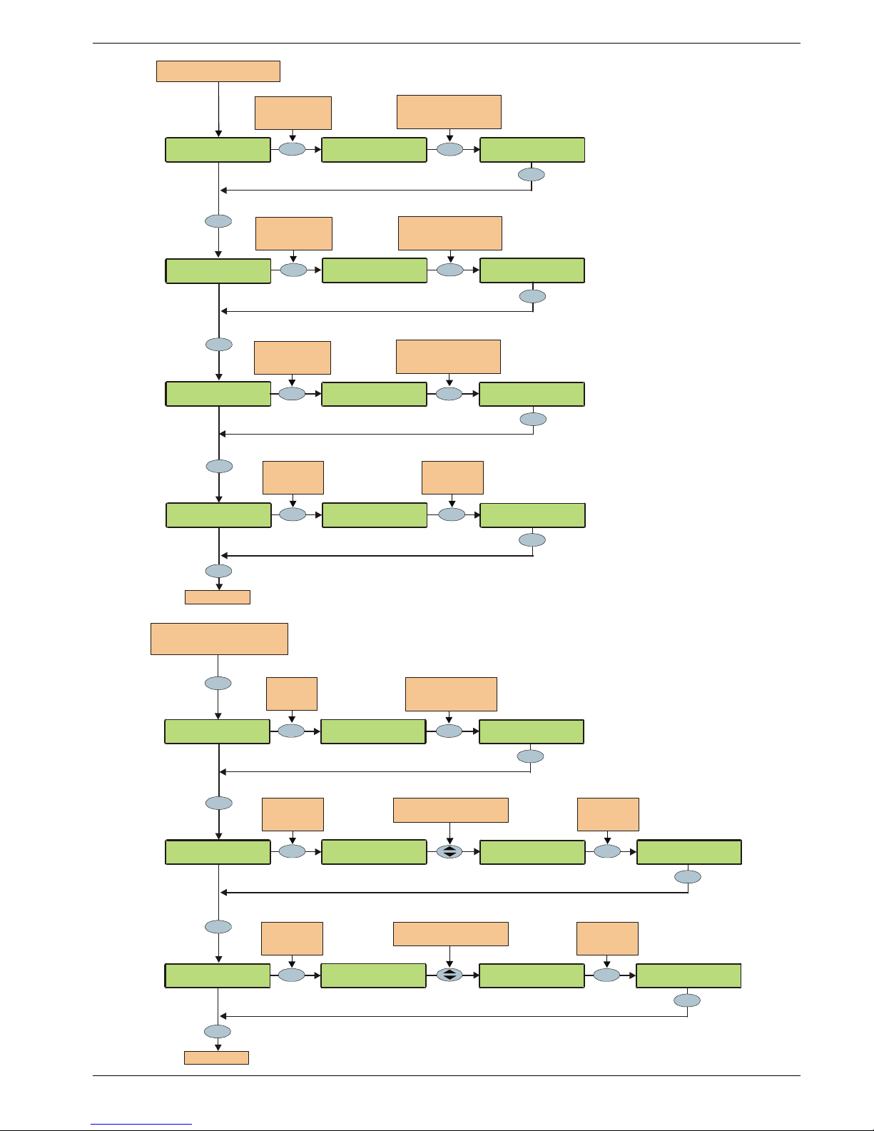
Premier 640 Installation Manual Programming the Control Panel
INS344 69
2, 3
Yes
No
Yes
Yes
No
4
ghi
;$O0):589!08Z
!!!!11111111
2, 3
No
Yes
Yes
;
$O0):589!08Z
!!W!1*f11111
;$O0):589!08Z
!!W!11111111
From previous page if
Fast Form at protocol i s sele cted
;$<:0)589!08Z
!!!!11111111
;$<:0)589!08Z
!!W!1*f11111
;$<:0)589!08Z
!!W!11111111
Use keys 1 - 8 to select
the Reporting channels
e.g. 2 & 3 = channels 2, 3
Press NO to edit
the reporting
channels
Press NO to edit
the repo rting
channels
HO$8]6-0<$!08Z
!!!!11111111
HO$8]6-0<$!08Z
!!W!111g1111
HO$8]6-0<$!08Z
!!W!11111111
Use keys 1 - 8 to select
the Restoring channels
e.g. 2 & 3 = channels 2, 3
Press NO to edit
the Open/Close
channels
Use keys 1 - 8 to select
the Open/Close channels
e.g. 2 & 3 = channels 2, 3
,08B59Z
!1!1!1!1!1!1!1!
No
Yes
\
<$!.)$(!.66
W
1!1!1!1!1!1!1
Press NO to
edit the
reports options
\<$!.)$(!.66
W.!1!1!1!1!1!1
No
Press NO to
change the
reports o ption
Yes
Back to the start
Yes
;$O0):<Z
!1!1!1!1!1!1!1!1
No
Yes
I)50)5:=!.-/
W1!1!1!1!1!1!1!1
From pr evio us pag e if C ontact ID,
SIA Level II, EasyCom Pager or SMS
Messaging protocols a re select ed
Press NO to
edit the
reports o ptions
Use the SCROLL key to select
the required Reports option
L0)/(-!.-()/
!1W1!1!1!1!1!1!1
No
L
0)/(-!.-()/
!1
W.
!1!1!1!1!1!1!
Press NO to
change the
reports option
;$O0):!.)$(<!Z
!!!!11111111
Yes
1
No
Press NO to
edit the
report areas
;$O0):!.)$(<!Z
!!W!11111111!l
;$O0):!.)$(<!Z
!!W!.1111111!l
Yes
Use keys 1 - 8 to select
the Report areas
e.g. 1 = area A
Yes
,08B59Z
!1!1!1!1!1!1!1!
No
Yes
\
<$!.)$(!.66
W
1!1!1!1!1!1!1!
Press NO to
edit the
reports o ptions
Use the SCROLL key to select
the required Reports option
\<$!3_.!_
!1W1!1!1!1!1!1!
No
\
<$!
3_.!_
!1W3!1!1!1!1!1!
Press NO to
change the
reports option
Yes
Back to the start
Yes
Page 70
Programming the Control Panel Premier 640 Installation Manual
70 INS344
The plug-on communicator can be programmed to dial up to
3 sets of Alarm Receiving Centre (ARC) information. Each ‘Set’
consists of the following options:
Protocol
This is the reporting protocol that is used to communicate
with the Alarm Receiving Centre. The following 4 protocols
are supported:
• Fast Format: The panel will report using Fast Format. If
this option is selected the ‘Reporting Channels’ must be
programmed (see below)
• Contact ID: The panel will report using Contact ID. If this
option is selected, the ‘Reporting Areas’ must be
programmed (see below)
• SIA Level II: The panel will report using SIA Level II
• EasyCom Pager: The panel will report to an EasyCom
type pager
• SMS Messaging: The panel will send Short Message
Service (SMS) text messages to a mobile phone
Primary Telephone Number
This is the first telephone number that the communicator will
dial for the Alarm Receiving Centre or the first mobile
telephone number to send SMS to. Each telephone number
can be up to 24 digits.
Secondary Telephone Number
This is the second telephone number that the communicator
will dial for the Alarm Receiving Centre or the second mobile
telephone number to send SMS to. Each telephone number
can be up to 24 digits.
Account Number
This is the account number that will be reported to the Alarm
Receiving Centre. Each account number can be up to 6 digits.
!
Each area can also have its own account number (see
page 71 for details).
Dialling Attempts
This is the number of times the communicator will try to dial the
Alarm Receiving Centre or Pager telephone number.
!
The number of dialling attempts is limited to 9. If this value
is set to 0, the communicator will never dial out.
The following option is only displayed if the
Fast Format protocol is selected
Reporting on
This option defines which channels report to the selected
Alarm Receiving Centre.
Restoring on
This option defines which channels report a restore to the
selected Alarm Receiving Centre.
Open/Close on
This option defines which channels report Open/Close to the
selected Alarm Receiving Centre.
The following option is only displayed if Contact ID
or SIA Level II protocols are selected
Reporting Areas
This option defines which areas report events to the
selected Alarm Receiving Centre.
The following option is only displayed if Contact ID,
SIA Level II or EasyCom Pager protocols are selected
Reports
This option defines which events report to the Alarm
Receiving Centre when using Contact ID or SIA Level II.
P - Priority Alarm and Cancel Events
The system will report Priority alarm and cancel events to
the selected Alarm Receiving Centre.
A - Normal Alarm and Cancel Events
The system will report alarm and cancel events to the
selected Alarm Receiving Centre.
O - Open and Close Events
The system will report open and close events to the
selected Alarm Receiving Centre.
B - Omit and Reinstate Events
The system will report omit and reinstate events to the
selected Alarm Receiving Centre.
M - Maintenance Alarm Events
The system will report maintenance alarm events to the
selected Alarm Receiving Centre.
T - Tamper Alarm Events
The system will report tamper alarm events to the
selected Alarm Receiving Centre.
C - Test Call Events
The system will report test call events to the selected
Alarm Receiving Centre.
R - Restore Events
The system will report restore events to the selected
Alarm Receiving Centre.
The following option is only displayed if Fast Format
Contact ID or SIA Level II protocols are selected
Config.
This option defines which secondary options are enabled.
A - Area Account
Events are reported to the Alarm Receiving Centre using
the area account numbers (see page 71 for details).
S - SIA Level I / UCP
Events are reported to the Alarm Receiving Centre using
SIA Level I or or to an SMS Messaging Server using UCP.
R - Enable Radio-Pad
The system will use the Paknet radio-pad to report events
to the selected Alarm Receiving Centre.
G - Enable GSM Module
The system will use the GSM Module to report events to
the selected Alarm Receiving Centre.
A - AV Module
The AV Module will dial the Alarm Receiving Centre.
F - Use GSM First
The GSM module is the primary path when this is enabled
I - Connect Via IP
The system will use the IP Module to report events to the
selected Alarm Receiving Centre.
T - Send SIA Text
Text is sent to the Alarm Receiving Centre when using
SIA II (this makes the protocol SIA III)
Page 71
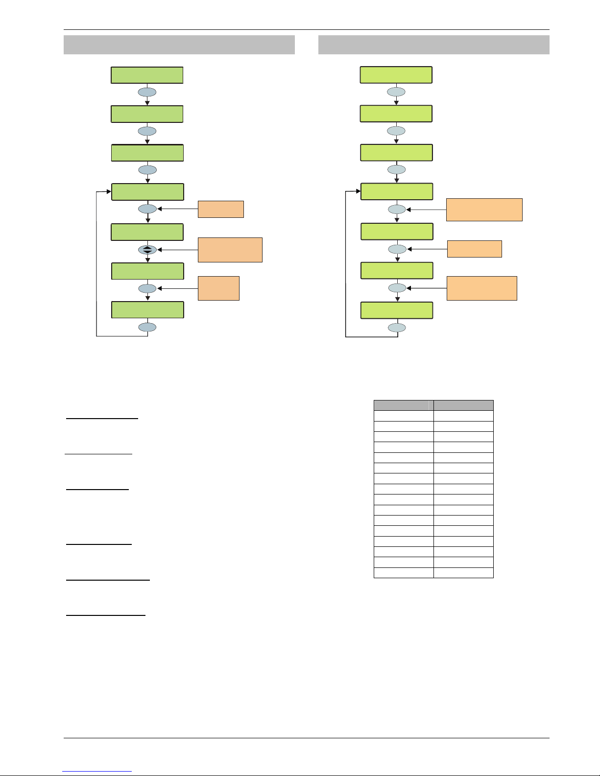
Premier 640 Installation Manual Programming the Control Panel
INS344 71
Digi Options
>73!:0!3$-$6:Z[
\C?]C595!HO:5
08<
Yes
\C?]C595!HO:508<
;$<$:!C595
C595!HO:508<
!1!1!1!1!1!1
Press NO to edit
the Digi option
No
4
ghi
C595!5<!78(E-$D
W1!1!1!1!1!1
No
N-58D!C5(--589
!1!1!1W1!1!1!
\C?]C595!HO:5
08<
C595!HO:508<
Yes
Use keys 1 - 8 to select
an opti on or use the
SCROLL key to search
Yes
N-58D!C5(--589
!1!1!1WN!1!1!
Press NO to
select/deselect
the option
There are 6 options that control how the plug-on
communicator works.
Select options by pressing keys 1 to 8 (a letter on the display
means the option is selected, a Dot on the display means the
option is not selected).
E - Digi is Enabled
The plug-on communicator will report all system events to the
Alarm Receiving Centre.
P - Pulse Dialling
The plug-on communicator will always dial telephone
numbers using pulse dialling.
3 - Pulse After 3
The plug-on communicator will always dial telephone
numbers using tone dialling. However, if the Communicator
fails to dial the number three times in a row, it will revert to
pulse dialling for the remaining attempts.
B - Blind Dialling
The plug-on communicator will not look for a dial tone before
dialling a telephone number.
U - Use MSN/Pre-Dial
The ComISDN will only answer a call when the programmed
MSN/Pre-Dial telephone number is dialled.
A - Dial All Numbers
If the communicator is acknowledged by the first ARC, it will
continue to dial any other programmed ARC. This is normally
used when a second or third ARC is programmed with SMS
Messaging.
Area Accounts
YES to Select:UDL/Digi Options
Yes
UDL/Digi Options
Reset Digi
Area 01 Account:
Press NO to edit
the account number
????
No
6
mno
UDL/Digi Options
Area Accounts
Yes
Area 02 Account:
^ >123
Use keys 0 - 9 to enter
the account number
e.g. 1234 = Account 1234
Area 02 Account:
--1234
Yes
Enter Area number (01-16)
ie 02 = Area 02
(Area No. 01= Area A1)
??
When using Fast Format, Contact ID or SIA, areas A1 to B8
can have their own account number to identify events.
Accounts are selected as account numbers 01 to 16 and they
refer to the system areas as follows.
Selected Panel Area
01 A1
02 A2
03 A3
04 A4
05 A5
06 A6
07 A7
08 A8
09 B1
10 B2
11 B3
12 B4
13 B5
14 B6
15 B7
16 B8
The programmed account number will be reported to the
Alarm Receiving Centre when any reportable event occurs.
Each account number can be up to 6 digits.
!
In order for the control panel to use the area account
numbers, the area account Config. option must be
enabled (see page 70 for details).
Page 72
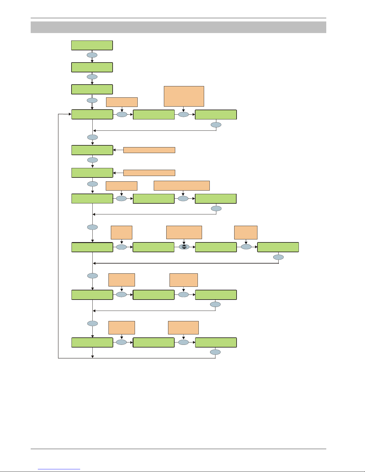
Programming the Control Panel Premier 640 Installation Manual
72 INS344
UDL Options
>73!:0!3$-$6:Z[
\C?]C595!HO:508<
\C?]C595!HO:508<
;$<$:!C595
Yes
Yes
Yes
No
,(--!N(6G!L01!+
!!
Press NO to
edit the
UDL Options
;589<!)$U#5)$DZ
!!!!!!!%%%
Yes
Enter the number
of rings require d
e.g. 3 = 6 rings
Yes
5
jkl
Yes
No
????
Use keys 0 - 9 to enter
the telephone num ber
Omit = *, Chime = #
Part = 3 second Pause
Area = 10 Second Pause
No
Press NO to
edit the
Rings required
Yes
\C?]C595!HO:508<
\C?!HO:508<
Yes
????
No
Yes
Press NO to edit the
Call Back number
h!!!!!!!!!!!W+*f
cS%Xk%+*fgA&k!
!!!h!!!!!!!!W+*f
,(--!N(6G!L01!*
!!
\C?!I(<<J0)D!5<Z
Press NO to edit the
UDL Password
Yes
,(--!N(6G!L01!f
!!
Yes
Follow Call Back No .1 Instructions
Follow Call Back No .1 Instructions
Use keys 0 - 9 to program text the
same way that a mobil e phone works
h7D5:!"$P:!!W.N,
.N,+*f
!7D5:h"$P:!!W+*f
No
;589<!)$U#5)$DZ
!!!!!W!%%%
;589<!)$U#5)$DZ
!!!!!W!%%&
6
mno
C5(--589!.::$/O:<
!!!!!!!!%%
Yes
3
def
Enter the number
of dialling attempts
e.g. 3 = 3 attempts
No
Press NO to
edit the
Dialling Attempts
C5(--589!.::$/O:<
!!!!!!W!%%
C5(--589!.::$/O:<
!!!!!!W!%f
Yes
\C?!HO:508<
!1!'!C!1!1!1
Use keys 1 - 8 to select
an opti on or use the
SCROLL key to search
Press NO to
select /desele ct
the option
C?!.::$8D$D
W1!'!C!1!1!1
,(--!C$B$(:!HL
!1!'WC!1!1!1
,(--!C$B$(:!H8
!1!'W1!1!1!1
Page 73

Premier 640 Installation Manual Programming the Control Panel
INS344 73
The system has the following UDL download options:
Download Call Back Number 1
This is the telephone number that is dialled by the modem
when ‘Call-back Number 1’ is requested by the remote UDL
computer. This telephone number can be up to 24 digits.
Download Call Back Number 2
This is the telephone number that is dialled by the modem
when ‘Call-back Number 2’ is requested by the remote UDL
computer. This telephone number can be up to 24 digits.
Download Call Back Number 3
This is the telephone number that is dialled by the modem
when ‘Call-back Number 3’ is requested by the remote UDL
computer. This telephone number can be up to 24 digits.
UDL Password is:
When the remote downloading computer dials into the system,
the control panel compares the UDL password sent by the
computer with UDL password stored in the control panel. If the
passwords match, access to the control panel is granted, if
they don’t match, access is denied.
!
If more than three attempts at reporting are made with
a wrong password, the modem will lock out for 4 hours
or until a Master User code is entered.
The UDL password programmed in this option must
also be programmed in the customer account on the
remote downloading computer. This password can be
up to 16 characters (numbers and letters).
If no UDL Password has been programmed, access to
the control panel can be gained by using the engineers
code as the UDL Password.
UDL Options
There are 6 UDL options that affect how and when access to
the control panel via the Wintex UDL software is allowed.
Select options by pressing keys 1 to 6 (a letter on the display
means the option is selected, a Dot on the display means the
option is not selected).
The following UDL options are available:
A - DL Attended
The system will not allow the remote downloading computer
access without user authorisation first.
M - Man Call-Back
The system will not use the automatic call back feature. The
user must instruct the panel to call back the remote
downloading computer.
The Auto Call-Back feature operates as follows:
• The remote downloading computer calls the control
panel and establishes a connection
• The UDL password is verified and the remote
downloading computer instructs the panel to call it
back using one of the 3 call back numbers
• The panel hangs up and dials the requested number
and re-establishes the connection with the remote
downloading computer
D - Call Defeat
The modem will answer incoming calls as follows:
• The modem must detect one or more rings and the
number of rings must NOT exceed the value set up in
‘Rings Required’
• When the ringing stops, the panel will start a 30
second delay timer
• If the modem detects ringing before the timer expires
it will answer the call immediately
L - Armed DL Limited
The panel will not allow download access when the system is
armed (also see below).
A - Any Area Armed
The panel will not allow download access when any areas are
armed.
K - Online RKP = Off
The control panel cannot be accessed using the ‘On-line’
keypad feature of the Wintex UDL software.
Rings Required
This counter controls the number of rings the modem needs
to see before it will answer the call (Default = 003).
UDL Dial Attempt
If a ‘Call-Back’ is started, this option controls how many times
the modem will try to call the remote downloading computer
before giving up (Default = 003).
!
Enter the number of dialling attempts. This number is
limited to 9. If this value is set to 0, the communicator will
never dial out.
This only affects the modem for download access and
does not affect the operation of the communicator in
any way.
Page 74
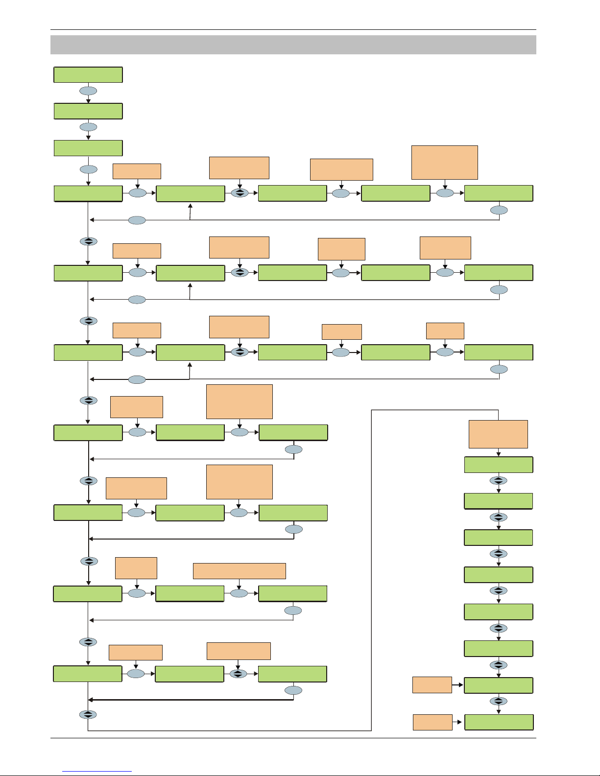
Programming the Control Panel Premier 640 Installation Manual
74 INS344
Radio/SMS Options
>73!:0!3$-$6:Z[
\C?]C595!HO:508<
\C?]C595!HO:508<
;$<$:!C595
Yes
7
pqrs
\C?]C595!HO:508<
;(D50]3'3!HO:508
I(D!.;,!+!I)5!L0!
h
!!!!!! !!!! !
W+*f
Yes
+*f
!!!h!!!!!!!!
W+*f
Use keys 0 - 9 to enter
the telephone number
Omit = *, Chim e = #
Part = 3 seco nd Pau se
Area = 10 Second Pause
????
3$:#O!;(D50[I(D`
Yes
Press YES to setup
the Radio-Pad
Yes
Use keys 0 - 9 to select
an option or use the
SCROLL key to search
I(D!.;,!f!I)5!L0
No
Press NO to edit the ARC
Primary
telephone number
Radio-Pad
.T!L01+W!
.T!C5(-!.::
$/O:<
!!!!!W!%f
Yes
+*f
!!!h!!!!!!!!
W+*f
5
jkl
3$:#O!.T!'0D#-$`
Yes
Press YES to setup
the Radio-Pad
Use keys 0 - 9 to select
an option or use the
SCROLL key to search
.T!C5(-!.::$/O:<
!!!!!!!%f
No
Press NO to enter
the number of
dialling attempts
Enter the number
of dialling attempts
e.g. 5 = 5 attempts
No
3'3!,$8:)$!I)51!
Yes
3'3!,$8:)$!3$61
Yes
h
!!!!!! !!!!!
W+*f
No
????
Use keys 0 - 9 to enter
the telephone number
Omit = *, Chime = #
Part = 3 seco nd Pau se
Area = 10 Second Pause
Press NO to edit the
SMS Centre Primary
telephone number
Press NO to edit the
SMS Centre Secondary
telephone number
h!!!!!!!!!!!W+*f
%kXc%+*fgA&
!!!!!!!!!! W+*fh!
Use keys 0 - 9 to enter
the telephone number
Omit = *, Chime = #
Part = 3 seco nd Pau se
Area = 10 Second Pause
????
No
'0D
$/!3$:#O!
3:9
1
Yes
'0D
$/!3O$$DZ
!!!!!!*g%%!
Yes
No
Press NO to
edit the Modem
setup string
Press NO to change
the Modem s peed
h!!!!!!!!!!!W+*f
m,e3LdfS%S%S%
!!!!!!!!!!!! +*fh
????
%kXc%+*fgA&
!!!!!! !!!
W+*f
h!
'0D$/!3O$$DZ
!!!!W!gX%%!
'0D$/!3O$$DZ
!!!!W!c&%%!
I(D!3$)5(-!L
01Z
!!!%%%%%+*fgA&
I(D!L\.Z!+*fgA&k
233Z%+&!aWd%fb
;33Z%Xc!aWdA%b
3598(-
Z
Premier 640 Installation Manual Programming the Control Panel
INS344 75
The following options are used when a Paknet Radio-Pad is
connected to the control panel in order to achieve DUAL
SIGNALLING to an Alarm Receiving Centre, when a MODEM
(External PC or Com2400) is used to connect to the control
panel or send SMS messages to mobile phones, when an AV
Module is connected to the control panel in order to achieve
AUDIO VERIFICATION to an Alarm Receiving Centre or when
a TCP/IP Module is connected for communications over a
Broadband/ADSL/DSL Line.
Setup Radio-Pad
Pad ARC 1 Pri No
This is the first number that is used by the Radio-Pad for
reporting events to ARC 1.
Pad ARC 1 Sec No
This is the second number that is used by the Radio-Pad for
reporting events to ARC 1.
Pad ARC 1 Prefix
This number will prefix the account number for ARC 1.
Pad ARC 2 Pri No
This is the first number that is used by the Radio-Pad for
reporting events to ARC 2.
Pad ARC 2 Sec No
This is the second number that is used by the Radio-Pad for
reporting events to ARC 2.
Pad ARC 2 Prefix
This number will prefix the account number for ARC 2.
Pad ARC 3 Pri No
This is the first number that is used by the Radio-Pad for
reporting events to ARC 3.
Pad ARC 3 Sec No
This is the second number that is used by the Radio-Pad for
reporting events to ARC 3.
Pad ARC 3 Prefix
This number will prefix the account number for ARC 3.
Radio-Pad Attempts
This is the number of times the Radio-Pad will try to dial the
Alarm Receiving Centre telephone number before giving up.
!
The number of dialling attempts is limited to 9. If this
value is set to 0, the Radio-Pad will never dial out.
Setup AV Module
AV No. 1>
This is the first number that is dialled by the AV Module.
AV No. 3>
This is the second number that is dialled by the AV Module.
AV No. 3>
This is the third number that is dialled by the AV Module.
AV Dial Attempts
This is how many times the AV Module will attempt to dial
before giving up.
!
The number of dialling attempts is limited to 9. If this
value is set to 0, the AV Module will never dial out.
AV Re-Dial Delay
This is the amount of delay that the AV Module uses between
re-dialling telephone numbers.
Setup IP Module
ComIP Address
This is the IP Address of the IP Module.
ComIP Port
This is the Port number of the IP Module.
ComIP Gateway
This is the Gateway IP Address that the IP Module
communicates through.
ComIP Mask
This is the Subnet Mask number for the IP Module.
Polling/SMG Address
This is the IP address of a dedicated Polling or SMG Server
that the IP Module might need to connect to.
Name/SMG Port
This is a descriptive name for the IP Module or SMG Port and
might be used for authentication purposes.
SMS Centre Pri.
This is the first SMS centre telephone number that is used by
for sending SMS to mobile phones. (Default = 07860
980480).
SMS Centre Sec.
This is the second SMS centre telephone number that is used
by for sending SMS to mobile phones.
Modem Setup Stg.
If a standard PC modem is connected to Com1 or Com2, it
may require a configuration string to make it work properly
(please refer to instruction manual of modem being used for
details of required AT commands).
!
The Setup string is programmed the same way that
TEXT would be programmed and has a maximum
length of 16 characters.
The setup string does NOT require AT to be entered at
the beginning as this is done automatically.
Modem Speed
This option allows the speed of a standard PC modem
connected to Com1 or Com2 to be adjusted.
Pad Serial No.
This screen displays the Serial number of the Radio-Pad that
is connected.
Pad NUA
This screen displays the NUA number of the Radio-Pad that is
connected.
Last Call From
This screen displays the NUA number of the last Radio-Pad
that communicated with the Radio-Pad that is connected to
the control panel.
FSS:??? (>=004), Forward Signal Strength
RSS:??? (>=050), Reverse Signal Strength
This screen displays the Radio-Pad Forward (FSS) and
Reverse (RSS) Signal Strength of the Radio-Pad that is
connected to the control panel.
!
The FSS value should be greater than or equal to 4 and
the RSS value should be greater than or equal to 50.
Page 76
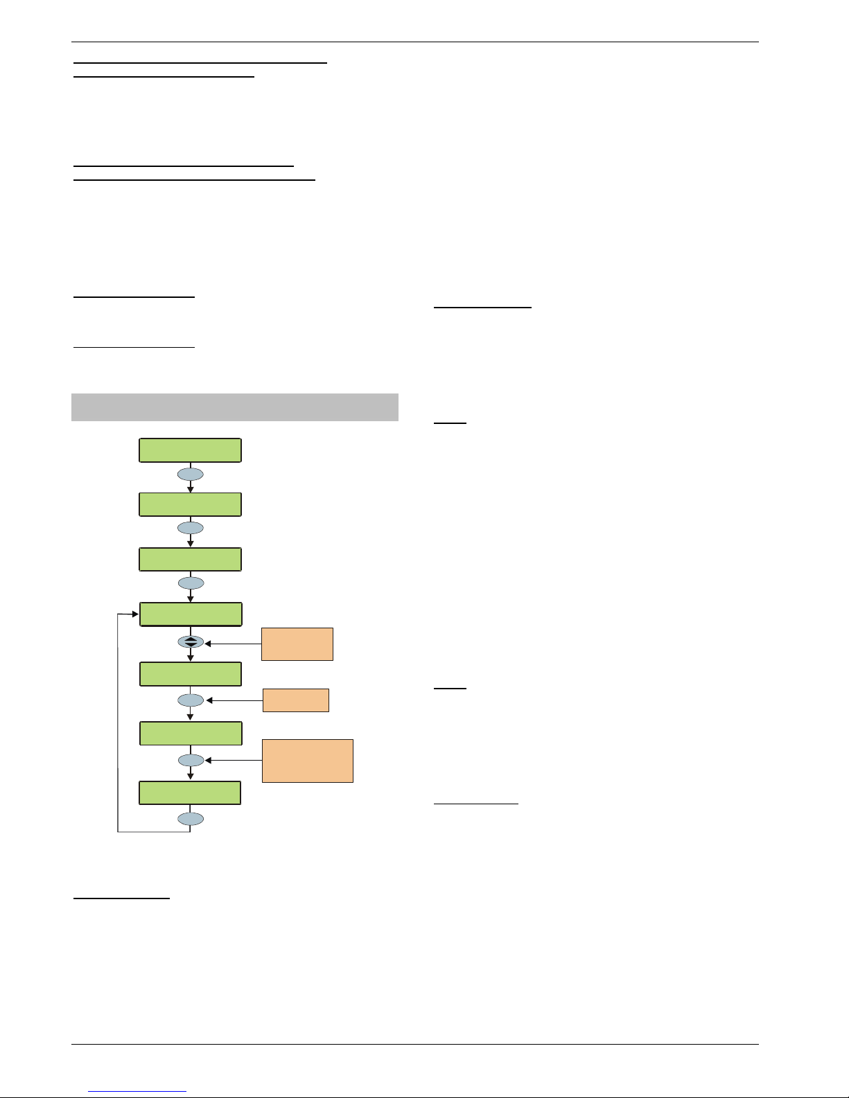
Programming the Control Panel Premier 640 Installation Manual
76 INS344
CRC:??? (<=009), Cyclic Redundancy Check
BER:??? (<=009), Bit Error Rate
This screen displays the Cyclic Redundancy Check (CRC)
and Bit Rate Error (BER) of the Radio-Pad that is connected
to the control panel.
!
The CRC and BER values should be less than 10.
Signal =??? dBm (<=080), GSM Signal
GSM BER:??? (<=004), GSM Bit Error Rate
This screen displays the signal strength (GSM) and Bit Rate
Error (BER) of a GSM Module that is connected to the control
panel.
!
The GSM value should be greater than or equal to 80
and the BER value should be less than 9.
Com1 Monitor Screen
This screen allows you to view the data activity of Com1.
Press RESET to reset the device connected to this port.
Com2 Monitor Screen
This screen allows you to view the data activity of Com2.
Press RESET to reset the device connected to this port.
Com Port Setup
>73!:0!3$-$6:Z[
\C?]C595!HO:508<
\C?]C595!HO:508<
;$<$:!C595
Yes
8
tuv
H8E0()D!C59560/
,0/f%%!'0D#-$
\C?]C595!HO:508<
,0/!I0):!3$:#O
,
0/!I0):!
+
L0!'0D#-$!25::$D
No
,
0/!I0):!
+
L0!'0D#-$!25::$l
,0/!I0):!+
V3'!'0D#-
$!!!!!
l
7
pqrs
Yes
Press NO to edit
the Com Port
Use the SCROLL
key to select the
requi red Com Port
Yes
Use keys 0 - 8 to select
an device or use the
SCROLL key to search
e.g. 7 = GSM Module
The control panel must be programmed with the type of
device that are connected to each of its coms ports.
Com Port 1 and 2
Available Device Types:
0: No Module Fitted - No Devices/PC-Com/ USB-Com
1: Com300 - Com300 Communicator.
2: Com2400 - Com2400 Communicator.
3: ComISDN - ComISDN Communicator.
4: ComIP - ComIP TCP/IP Communication Module.
5: Modem Unit - Standard Serial PC Modem.
6: Radio Pad - Paknet RP9 Radio-Pad.
7: GSM Module - GSM Module/Mobile Phone.
8: Crestron System - Crestron Home Automation System.
9: SIP - Serial IP Protocol.
10: RadioPlus - Premier Serial Wireless Receiver.
11: Inovonics Radio - Inovonics Serial Wireless Receiver.
12: WebWayOne - WebWayOne UDP Module.
13: X-10 Control - X-10 Home Automation Module.
14: IRIS IP - Chiron IRIS Serial TCP/IP Module.
Onboard Digicom
This option determines what type of device is connected to
the plug-on digmodem connector on the top right hand
corner of the control panel. (Default = Com300).
Available Device Types:
0 / 1 / 2 / 3
Com1
This option determines what type of device is connected to
the Com1 connector on the left hand side of the control
panel. (Default = No Module Fitted).
Available Device Types:
0 / 2 / 3 / 4 / 5 / 7 / 8 / 9 / 10 / 12 / 13 / 14
!
If any of the above devices are connected to the
control panel on Com1 and a PC needs to be
connected (for uploading/downloading) the device
must be disconnected from Com 1 and the ‘Factory
Default’ button pressed for 3 seconds to allow the PC
to talk to the control panel.
If the PC is not connected to the control panel (or is
removed) the Com port will automatically revert back to
normal operation after 1 minute.
Com2
This option determines what type of device is connected to
the Com2 connector on the left hand side of the control
panel. (Default = No Module Fitted).
Available Device Types:
0 / 2 / 3 / 4 / 5 / 6 / 7 / 8 / 9 / 10 / 11 / 12 / 13 / 14
Expansion Port
This option determines what type of device is connected to the
Expansion Port connector (Default = No Module Fitted).
Available Device Types:
0: No Module Fitted - No Devices
1: AV Module - Premier Audio Verification Module
2: iD Module - Premier 60IXD iD Module
3: X10 Module - X10 Controller
4: Premier OP8 - Premier Output Module (8 Outputs)
Page 77

Premier 640 Installation Manual Programming the Control Panel
INS344 77
Page 78
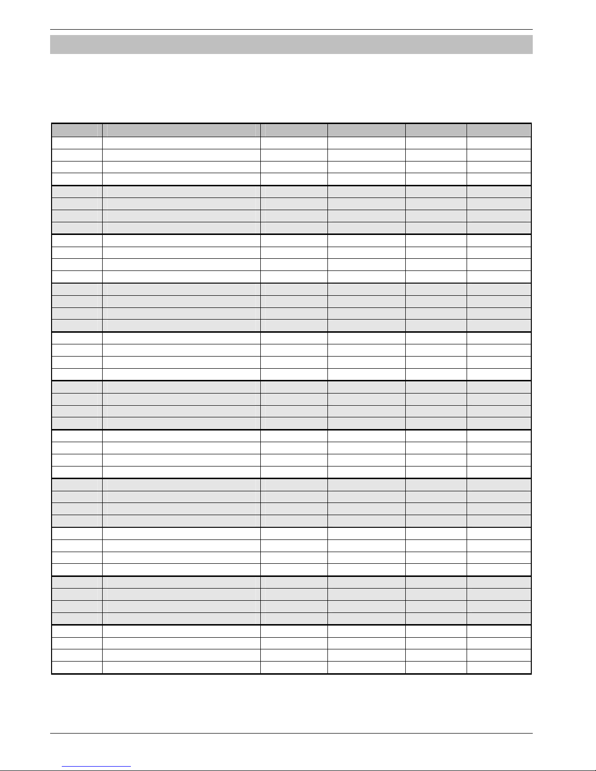
Programming the Control Panel Premier 640 Installation Manual
78 INS344
Zone Alarm Reporting Codes
The Reporting codes for Contact ID and SIA are fully configurable, however these codes can only be changed using Wintex
downloading software.
The following tables show the default codes for each event on the system:
Default Zone Event Codes
No Zone Type Event Reporting Group Contact ID SIA
00 Entry/Exit 1 Alarm Alarm 134 BA
Alarm Restore Restore 134 BH
Omit Omit/Reinstate 573 BB
Reinstate Omit/Reinstate 573 BU
01 Entry/Exit 2 Alarm Alarm 134 BA
Alarm Restore Restore 134 BH
Omit Omit/Reinstate 573 BB
Reinstate Omit/Reinstate 573 BU
02 Guard Alarm Alarm 132 BA
Alarm Restore Restore 132 BH
Omit Omit/Reinstate 573 BB
Reinstate Omit/Reinstate 573 BU
03 Guard Access Alarm Alarm 132 BA
Alarm Restore Restore 132 BH
Omit Omit/Reinstate 573 BB
Reinstate Omit/Reinstate 573 BU
04 24Hr Audible Alarm Tamper 133 BA
Alarm Restore Restore 133 BH
Omit Omit/Reinstate 572 BB
Reinstate Omit/Reinstate 572 BU
05 24Hr Silent Alarm Tamper 133 BA
Alarm Restore Restore 133 BH
Omit Omit/Reinstate 572 BB
Reinstate Omit/Reinstate 572 BU
06 Audible PA Alarm Priority Alarm 123 PA
Alarm Restore Restore 123 PH
Omit Omit/Reinstate 573 PB
Reinstate Omit/Reinstate 573 PU
07 Silent PA Alarm Priority Alarm 122 HA
Alarm Restore Restore 122 HH
Omit Omit/Reinstate 573 HB
Reinstate Omit/Reinstate 573 HU
08 Fire Alarm Alarm Priority Alarm 110 FA
Alarm Restore Restore 110 FH
Omit Omit/Reinstate 571 FB
Reinstate Omit/Reinstate 571 FU
09 Medical Alarm Priority Alarm 100 MA
Alarm Restore Restore 100 MH
Omit Omit/Reinstate 572 MB
Reinstate Omit/Reinstate 572 MU
10 24Hr Gas Alarm Alarm Tamper 151 GA
Alarm Restore Restore 151 GH
Omit Omit/Reinstate 572 GB
Reinstate Omit/Reinstate 572 GU
Page 79
Premier 640 Installation Manual Programming the Control Panel
INS344 79
No Zone Type Event Reporting Group Contact ID SIA
11 Auxiliary Alarm Alarm Tamper 150 UA
Alarm Restore Restore 150 UH
Omit Omit/Reinstate 572 UB
Reinstate Omit/Reinstate 572 UU
12 24Hr Tamper Alarm Alarm Tamper 137 TA
Alarm Restore Restore 137 TR
Omit Omit/Reinstate 572 TB
Reinstate Omit/Reinstate 572 TU
13 Exit Terminator Alarm Open/Close --- --
Alarm Restore Open/Close --- --
Omit Omit/Reinstate 570 UB
Reinstate Omit/Reinstate 570 UU
14 Keyswitch - Momentary Alarm Open/Close 409 OP
Alarm Restore Open/Close 409 CL
Omit Omit/Reinstate 570 UB
Reinstate Omit/Reinstate 570 UU
15 Keyswitch - Latching Alarm Open/Close 409 OP
Alarm Restore Open/Close 409 CL
Omit Omit/Reinstate 570 UB
Reinstate Omit/Reinstate 570 UU
16 Security Key Alarm Open/Close 421 DK
Alarm Restore Open/Close 421 DG
Omit Omit/Reinstate 570 UB
Reinstate Omit/Reinstate 570 UU
17 Omit Key Alarm Omit/Reinstate --- --
Alarm Restore Omit/Reinstate --- --
Omit Omit/Reinstate 570 UB
Reinstate Omit/Reinstate 570 UU
17 Custom Alarm Not Reported --- --
Alarm Restore Not Reported --- --
Omit Not Reported --- --
Reinstate Not Reported --- --
Non-Zone Event Types
The default Non-Zone Event codes are as follows:
No Type Event Reporting Group Contact ID SIA ID
00 Keypad Medical Alarm Priority Alarm 100 MA Keypad No *
Restore Restore 100 MH Keypad No *
01 Keypad Fire Alarm Priority Alarm 115 FA Keypad No *
Restore Restore 115 FH Keypad No *
02 Keypad Audible PA Alarm Priority Alarm 120 PA Keypad No *
Restore Restore 120 PH Keypad No *
03 Keypad Silent PA Alarm Priority Alarm 122 PA Keypad No *
Restore Restore 122 PH Keypad No *
04 Duress Code Alarm Alarm Priority Alarm 121 HA User No
Restore Restore - 122 HH User No
05 Alarm Active Alarm Not Reported - - -
Restore Not Reported - - -
06 Bell Active Alarm Not Reported - - -
Restore Not Reported - - -
07 Zones Locked Out Alarm Alarm 130 BA Zone No
Restore Not Reported - - -
08 Verified Cross Zone Alarm Alarm Alarm 130 BV 00
Restore Not Reported - - -
Page 80

Programming the Control Panel Premier 640 Installation Manual
80 INS344
No Type Event Reporting Group Contact ID SIA ID
09 User Code Alarm Not Reported - - User No
Restore Not Reported - - -
10 Exit Started Alarm Not Reported - - Keypad No
Restore Not Reported - - -
11 Exit Error (Arming Failed) Alarm Open/Close 457 EE 00
Restore Not Reported - - -
12 Entry Started Alarm Not Reported - - -
Restore Not Reported - - -
13 Area Arm Suite Alarm Open/Close - - Suite No 1 - 8
Restore Open/Close - - -
14 Armed with Line Fault Alarm Not Reported - - User No
Restore Not Reported - - -
15 Open/Close (Full Arm) Alarm Open/Close 401 OP User No
Restore Open/Close 401 CL User No
16 Open/Close (Part Arm) Alarm Open/Close 401 OP User No
Restore Open/Close 401 CL User No
17 Auto Open/Close Alarm Open/Close 403 OA 00
Restore Open/Close 403 CA 00
18 Auto Arm Deferred Alarm Open/Close 405 CE User No
Restore Open/Close - - -
19 Open After Alarm (Alarm Abort) Alarm Open/Close 406 OR 00
Restore Not Reported - - -
20 Remote Open/Close Alarm Open/Close 407 OP 00
Restore Open/Close 407 CL 00
21 Quick Arm Alarm Not Reported - - -
Restore Open/Close 408 CL Keypad No *
22 Recent Closing Alarm Open/Close 459 CR 00
Restore Not Reported - - -
23 Reset After Alarm Alarm Restore - - Reset ID ****
Restore Not Reported - - -
24 Auxiliary 12V Fuse Fail Alarm Maintenance 300 YP Device ID **
Restore Restore 300 YQ Device ID **
25 AC Fail Alarm Maintenance 301 AT 00
Restore Restore 301 AR 00
26 Low Battery Alarm Maintenance 302 YT 00
Restore Restore 302 YR 00
27 System Power Up Alarm Maintenance 305 RR 00
Restore Not Reported - - -
28 Bell Fuse Failure Alarm Maintenance 321 YA 00
Restore Restore 321 YH 00
29 ATS Path Fault Alarm Maintenance 351 LT Line Fault ID ***
Restore Restore 351 LR Line Fault ID ***
30 Fail to Communicate Alarm Maintenance 354 YC 00
Restore Not Reported - - -
31 Download Start Alarm Maintenance 411 RB 00
Restore Not Reported - - -
32 Download End Alarm Maintenance 412 RS -
Restore Not Reported - - -
33 Log Capacity Alert (80%) Alarm Maintenance 623 JL 00
Restore Not Reported - - -
34 Date Changed Alarm Maintenance 625 JD User No
Restore Not Reported - - -
35 Time Changed Alarm Maintenance 625 JT User No
Restore Not Reported - - -
Page 81

Premier 640 Installation Manual Programming the Control Panel
INS344 81
No Type Event Reporting Group Contact ID SIA ID
36 Installer Programming Start Alarm Maintenance 627 LB User No
Restore Not Reported - - -
37 Installer Programming End Alarm Maintenance 628 LS User No
Restore Not Reported - - -
38 Panel Box Tamper Alarm Tamper 145 TA 00
Restore Restore 145 TR 00
39 Bell Tamper Alarm Tamper 145 TA Device ID **
Restore Restore 145 TR Device ID **
40 Auxiliary Tamper Alarm Tamper 145 TA Device ID **
Restore Restore 145 TR Device ID **
41 Expander Tamper Alarm Tamper 145 TA Device ID **
Restore Restore 145 TR Device ID **
42 Keypad Tamper Alarm Tamper 145 TA Keypad No *
Restore Restore 145 TR Keypad No *
43 Expander Trouble (Network Error) Alarm Tamper 333 ET Device ID **
Restore Restore 333 ER Device ID **
44 Keypad Trouble (Network Error) Alarm Tamper 333 ET Keypad No *
Restore Restore 333 ER Keypad No *
45 Fire Zone Tamper Alarm Tamper 373 FT Zone No
Restore Restore 373 FJ Zone No
46 Zone Tamper Alarm Tamper 383 TA Zone No
Restore Restore 383 TR Zone No
47 Keypad Lockout Alarm Tamper 421 JA Keypad No *
Restore Not Reported - - -
48 Code Tamper Alarm Alarm Tamper 421 JA Keypad No *
Restore Not Reported - - -
49 Soak Test Alarm Alarm Test - - Zone No
Restore Restore - - Zone No
50 Manual Test Call Alarm Test 601 RX 00
Restore Not Reported - - -
51 Automatic Test Call Alarm Test 602 RP 00
Restore Not Reported - - -
52 User Walk Test Start/End Alarm Test 607 TS User No
Restore Restore 607 TE User No
53 NVM Defaults Loaded Alarm Not Reported - - Zone No
Restore Not Reported - - Zone No
54 First Knock Alarm Not Reported - - -
Restore Not Reported - - -
55 Door Access Alarm Not Reported - - -
Restore Not Reported - - -
56 Part Arm 1 Alarm Not Reported - - -
Restore Close 401 CL User No
57 Part Arm 2 Alarm Not Reported - - -
Restore Close 401 CL User No
58 Part Arm 3 Alarm Not Reported - - -
Restore Close 401 CL User No
59 Auto Arming Start Alarm Not Reported - - -
Restore Close 401 CL 000
60 Confirmed Alarm Alarm Alarm 139 BV Zone No
Restore Not Reported - - -
61 Prox TAG Alarm Not Reported - - -
Restore Not Reported - - -
62 Access Code Changed/Deleted Alarm Not Reported - - -
Restore Not Reported - - -
Page 82

Programming the Control Panel Premier 640 Installation Manual
82 INS344
No Type Event Reporting Group Contact ID SIA ID
63 Arm Failed Alarm Not Reported - - -
Restore Not Reported - - -
64 Log Cleared Alarm Maintenance - - -
Restore Not Reported 401 CL 000
65 iD Loop Shorted Alarm Tamper 145 TA 000
Restore Restore 145 TR -
66 Communication Port Alarm Maintenance - - 000
Restore Restore - - 000
67 TAG System Exit (Batt. OK) Alarm Not Reported - - Zone No
Restore Not Reported - - Zone No
68 TAG System Exit (Batt. LOW) Alarm Not Reported - - -
Restore Not Reported - - -
69 TAG System Entry (Batt. OK) Alarm Not Reported - - -
Restore Not Reported - - -
70 TAG System Entry (Batt. LOW) Alarm Not Reported - - -
Restore Not Reported - - -
71 Microphone Activated Alarm Not Reported - - -
Restore Not Reported - - -
72 AV Cleared Doen Alarm Not Reported - - -
Restore Not Reported - - -
73 Monitored Alarm Alarm Alarm 220 BA Zone No
Restore Restore 220 BH Zone No
74 Expander Low Voltage Alarm Maintenance 143 ET Device No
Restore Restore 143 ER Device No
75 Supervision Fault Alarm Maintenance 355 UT Zone No
Restore Restore 355 UJ Zone No
76 PA From Remote FOB Alarm Priority Alarm 121 121 Zone No
Restore Restore HA HH Zone No
77 RF Device Low Battery Alarm Maintenance 384 XT Zone/User No
Restore Restore 384 XR Zone/User No
78 Site Data Changed Alarm Maintenance - - -
Restore Restore - - -
79 Radio Jamming Alarm Maintenance 344 XQ 000
Restore Restore 344 - 000
80 Test Call Passed Alarm Not Reported - - -
Restore Not Reported - - -
81 Test Call Failed Alarm Not Reported - - -
Restore Not Reported - - -
82 Zone Fault Alarm Maintenance 380 UT Zone No
Restore Restore 380 UJ Zone No
83 Zone Masked Alarm Alarm 380 UT Zone No
Restore Restore 380 UJ Zone No
84 Faults Overridden Alarm Maintenance - - 000
Restore Not Reported - - 000
85 PSU AC Fail Alarm Maintenance 301 AT Device No
Restore Restore 301 AR Device No
86 PSU Low Battery Fail Alarm Maintenance 302 YT Device No
Restore Restore 302 YR Device No
87 PSU Low Output Fail Alarm Maintenance 300 YP Device No
Restore Restore 300 YQ Device No
88 PSU Tamper Alarm Tamper 333 TA Device No
Restore Restore 333 TR Device No
Page 83
Premier 640 Installation Manual Programming the Control Panel
INS344 83
Tamper Fault ID ***
Panel ID is transmitted as follows:
Device ID
Panel 000
Keypad ID is transmitted as follows:
Network
RKP 1 2 3 4 5 6 7 8
1 11 21 31 41 51 61 71 81
2 12 22 32 42 52 62 72 82
3 13 23 33 43 53 63 73 83
4 14 24 34 44 54 64 74 84
5 15 25 35 45 55 65 75 85
6 16 26 36 46 56 66 76 86
7 17 27 37 47 57 67 77 87
8 18 28 38 48 58 68 78 88
Expander ID is transmitted as follows:
Network
EXP 1 2 3 4 5 6 7 8
1 11 21 31 41 51 61 71 81
2 12 22 32 42 52 62 72 82
3 13 23 33 43 53 63 73 83
4 14 24 34 44 54 64 74 84
5 15 25 35 45 55 65 75 85
6 16 26 36 46 56 66 76 86
7 17 27 37 47 57 67 77 87
8 18 28 38 48 58 68 78 88
ATS Path Fault ID ***
Line Fault ID is transmitted as follows:
Device ID
Panel 00
RedCARE 01
Com300 03
Expander ID is transmitted as follows:
Network
EXP 1 2 3 4 5 6 7 8
1 11 21 31 41 51 61 71 81
2 12 22 32 42 52 62 72 82
3 13 23 33 43 53 63 73 83
4 14 24 34 44 54 64 74 84
5 15 25 35 45 55 65 75 85
6 16 26 36 46 56 66 76 86
7 17 27 37 47 57 67 77 87
8 18 28 38 48 58 68 78 88
Reset ID ****
Reset ID is transmitted as follows:
Device ID
Panel (RR) 00
Engineer 01
Anti-Code 02
RedCARE 03
Keyswitch 04
User 05
Wintex 07
Expander ID is transmitted as follows:
Network
EXP 1 2 3 4 5 6 7 8
1 11 21 31 41 51 61 71 81
2 12 22 32 42 52 62 72 82
3 13 23 33 43 53 63 73 83
4 14 24 34 44 54 64 74 84
5 15 25 35 45 55 65 75 85
6 16 26 36 46 56 66 76 86
7 17 27 37 47 57 67 77 87
8 18 28 38 48 58 68 78 88
Page 84
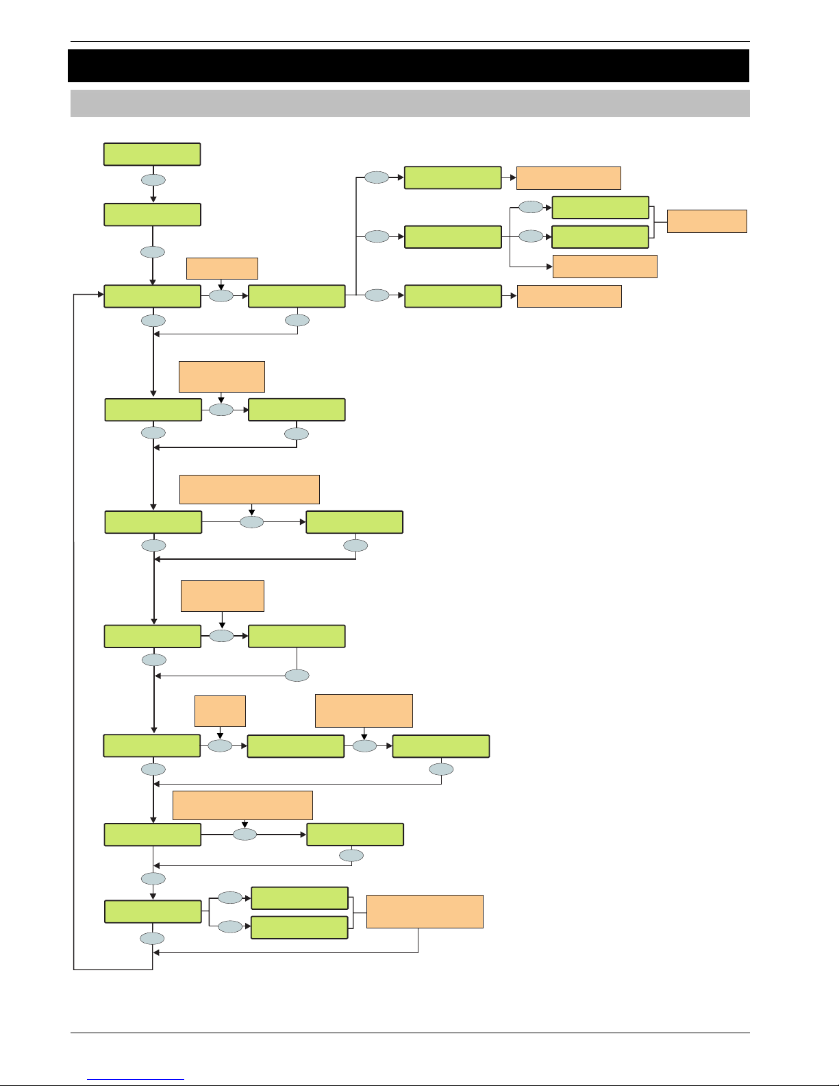
Programming the Control Panel Premier 640 Installation Manual
84 INS344
5.8 Setup Users
Add/Edit Users
??
Yes
Yes
????
Yes
Yes
Yes
Yes
Yes
Yes
Yes
Setup Users
Add/Edit Users
Setup Users
User002:
Enter User Code>
------
Enter User Number
i.e. 010 = User 10
User010 Area:
* * All Areas * *
User010 Area:
* * Area 01 * *
Setup Users
User010:
Enter User Code>
--1234
??
User 010 Type >
Manager
Enter the user profile
number
e.g. 03 = Manager
User 010 Type >
Standard
Enter User code number
4, 5 or 6 digits long
e.g. 1234 = 1234
^Edit Text >ABC
Use the keypad to program
text the same way that a
mobile phone works
Claire
Edit Text ^>ABC
Yes
No
User 10 Name is:
????
Press NO to
edit the User
name text
Yes
Yes
Present the Proximity TAG
to the ‘Prox’ symbol on the
keypad and a beep will be heard
No
Do You Want to
DELETE User 010?
Reset
Press YES to delete the
User from ths system
User 010 Remote >
Activate Device
Omit
Activate the Radio FOB to
assign it to the user
Press NO to exit ‘Add TAG’
Routine
Add TAG to User?
1=New, 2=Import
Area
YES to Select:Setup Users
ASSIGNING TAG
Present TAG Now!
IMPORTING TAG
Present TAG Now!
1
2
Present TAG to
assign it to user
Yes
Add TAG to User?
1=New, 2=Import
ASSIGNING TAG
Present TAG Now!
IMPORTING TAG
Present TAG Now!
1
2
User 010 Access:
No Door Access
Yes
User010 Access:
* * Area 01 * *
Use or enter Access Profile number
to select the Access Profile for this user
ie 01=Access Area 01
U
??
Use or enter Area Profile number
to select the Area Profile for this user
ie 01=Area Profile 01
U
??
Page 85
Premier 640 Installation Manual Programming the Control Panel
INS344 85
This section covers the alteration of existing users and the
addition of new users to the system. The Premier 640 can be
assigned up to 499 users (plus Engineer).
Default User Codes
When the control panel is first powered up and the factory
default settings are loaded (see page 28 for details), only the
Engineer code and the Master User code exist.
The Factory default Engineer User code is
!"#$.+
!
The Engineer is always User 000.
If the Engineer code has been lost or forgotten, it can
normally be reset back to the factory default without
having to reprogram the entire system (see page 33 for
details).
Resetting the Engineer code is only possible if the
NVM has not been locked (see page 49 for details).
+
The Factory default Master User code is
'()*.+
!
The Master User is always User 001.
+
If the Master User code has been lost or forgotten, it can
be reprogrammed by the Engineer in this menu.
+
Programming New Users
Each User code on the system is made up of the following
elements. Items 1, 2 or 7, 3 , 4 and 6 which are essential for the
code to function correctly and items 5, 7 and 8 which are
optional.
1. User Number
When users are assigned to the system, they need to be
identified by the control panel. Each user is identified as
Users 001, 002, 003 etc. User 001 is always the Master User.
2. User Code
This is a unique 4, 5 or 6 digit code number that is assigned to
a user. The system will allow a mixture of different length User
codes. The User code must be entered at a keypad to operate
the alarm system.
3. User Areas (Area Profile)
Any number of areas can be assigned to the selected user via
area profiles. Assigning areas to a user determines which areas
can be armed, disarmed, reset etc. by that user
When an Area Profile is assigned to a user, they are
automatically given access to all Areas assigned to the Area
Profile. Any subsequent changes to the Area Profile will
automatically change the areas available to all users assigned
to the profile..
4. User Types (User Profile)
The User type determines which functions are available to the
user , user types are setup as User Profiles and then allocated
to individual users.
When a User Profile is assigned to a user, the user is
automatically granted all of the functions set in the User
Profile. Any subsequent changes to the User Profile will
automatically carry through to all users assigned to the profile.
5. User Name Text
Each user can be assigned up to 8 characters of name text.
The name text is displayed whenever a code is entered and
also when reading the log, making identification of people
using the alarm easier.
6. Door Access (Access Profile)
Door control is assigned via Access Profiles which
determine which door strikes the user can control.
7. Proximity TAG
As well as or instead of operating the alarm system with a
code number, it is also possible to operate it by presenting a
Proximity TAG to the keypad (this requires a Proximity
keypad).
8. Radio FOB
As well as or instead of operating the alarm system with a
code number or Proximity TAG, it is also possible to operate
it Using a Wireless Radio Transmitter (this requires a Wireless
Radio Receiver keypad).
User Name Text
Each user can be assigned up to 8 characters of name text.
This can be beneficial when reading the log, as identification
of people is made easier.
See page 33 for details on programming text.
Text is programmed in a similar way to mobile phones. Select
characters by pressing the corresponding key the
appropriate number of times (to select a character on the
same key, press the
%
key to move the cursor along).
Deleting Users
If a User code needs to be deleted from the system, this must
be done, by a user that has access to the ‘Setup Users’
menu.
To delete User codes proceed as follows:
Ensure that Setup Users is selected, the display should
look like this:
C0!=0#!J(8:!:0
3$:#O!\<$)<`
Press 0, the display should look like this:
3$:#O!\<$)<!
78:$)!\<$)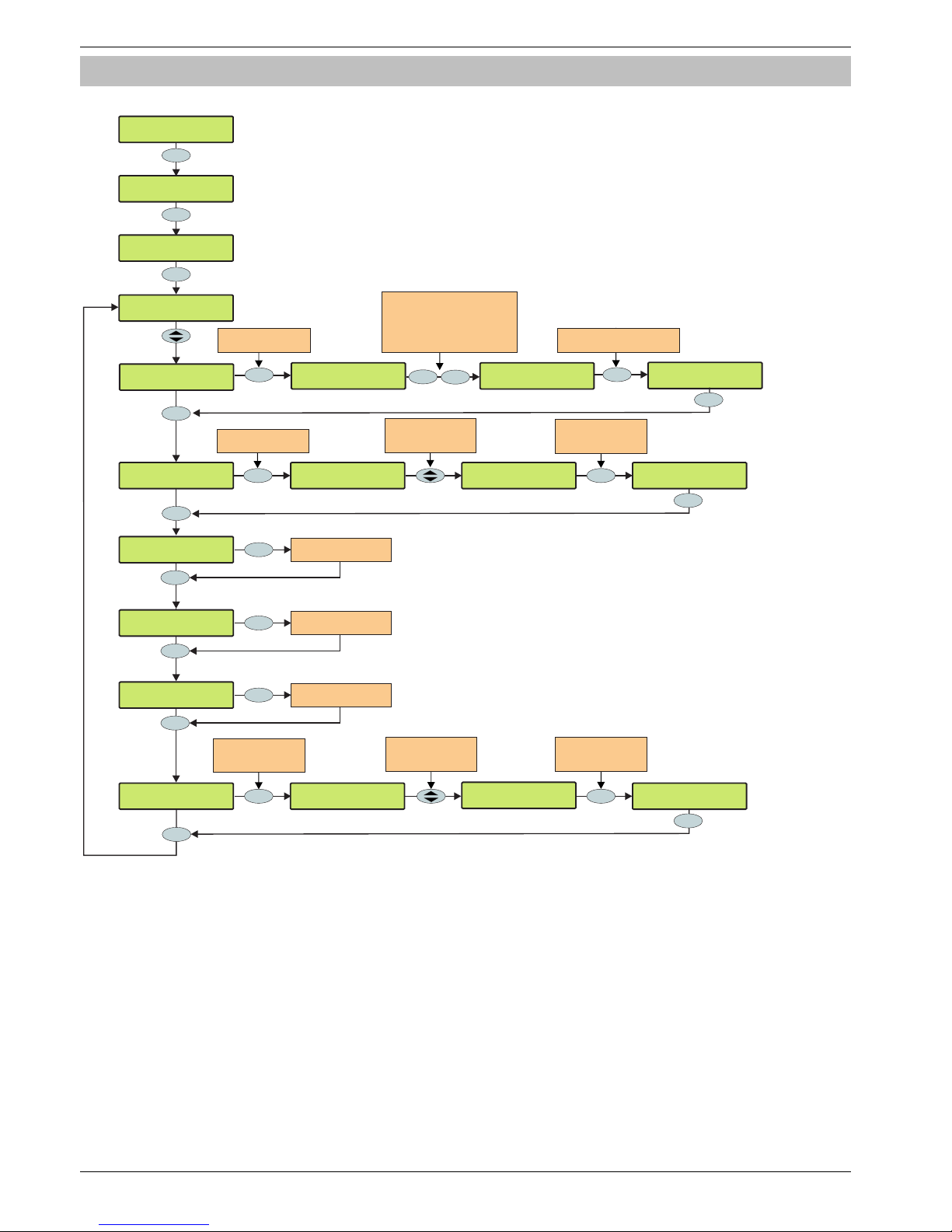
Programming the Control Panel Premier 640 Installation Manual
86 INS344
User Profiles
Yes
Yes
No
Setup Users
Add/Edit Users
Setup Users
User Profiles
01: Text:
Engineer
YES to Select:Setup Users
Yes
10: Text:
Custom 01
Custom 01
^Edit Text >TXT
Press NO to edit the
User Profile name text
Press NO followed by YES
to clear the screen or keep
pressing NO to change between
upper case, lower case,
numerical and predictive text
^Edit Text >CLR
No
Accounts Office
Edit Text >a^c
????
Use keys 2-9 to enter text as
you would on a mobile phone
Yes
Yes
10: Options1:
* * * * * * * *
Arming
>* * * * * * * *
Select user options
with keys 1 - 8
or use to searchU
No
No
Press NO to edit the
User Profile name text
Auto ?Yes?/Reset
A D O * * *>* *
Auto ?Yes?/Reset
A D O * * *>Y *
Pres NO to
select/deselect
the indicated option
Yes
Yes
10: Options2:
* * * * * * * *
No
Program user options 2
as per options 1 above
Yes
10: Options3:
* * * * * * * *
No
Program user options 3
as per options 1 above
Yes
10: Options4:
* * * *
No
Program user options 4
as per options 1 above
Yes
10: Locked by:
* * * * * * * *
No
Control Timer 1
>* * * * * * * *
Press NO to select
the timers that lock
this user out
No
Select Tmers
with keys 1 - 8
or use to searchU
Control Timer 6
1 * * 4 *>* * *
No
Control Timer 6
1 * * 4 *>6 * *
Pres NO to
select/deselect
the indicated timer
Yes
Yes
!
A number of preset User Profiles are provided as defaults (See Default User Profiles on page 88). These are equivalent to the
preset user types provided in previous versions of the 640. User Profiles 01 and 02 cannot be altered.
Page 87

Premier 640 Installation Manual Programming the Control Panel
INS344 87
User Profile Text
Each User Profile can be given a 16 character text name to
identify it. See page 33 for details of how to program text.
User Options
The user option menus define which options are available to
the users assigned to the User Profile when their code is
entered. There are 4 screens of user options, all are
programmed in the same way
Press
3 to edit options then either:
• Press
%
to scroll through the options and press
3
to toggle the selected option on and off, or:.
• use keys
!
-
*
(‘Letter’ = option IS selected,
‘Star’ = option is NOT selected).
User Options 1
A - Arming
Areas assigned to the selected user can be armed.
D - Disarming
Areas assigned to the selected user can be disarmed.
O - Omitting
Zones assigned to the same areas as the selected user can
be omitted, providing that they have the ‘omit’ attribute
assigned to them.
R - Eng. Reset (Engineers only)
Areas programmed as ‘Engineer reset’ can be reset after an
Alarm has occurred.
a - Local Arming
The User can only arm areas that the keypad is assigned to.
d - Local Disarm
The User can only disarm areas that the keypad is assigned to,
or areas that are in entry or alarm (provided that the code has
that area assigned to it).
Y - Auto ‘YES’
After a User code has been entered, pressing the 0 key to
confirm the next action is not required.
F - Disarm First
If an area is already armed and the selected user enters their
code, the ‘Disarm’ option is displayed.
User Options 2
U - User Menu
The selected user has access to the User menu. However,
the selected user will only have access to options assigned in
‘User Options 3’.
E - Eng. Program (Engineers only)
Only Available to Engineers.
D - Dual Code
The selected user can only access an area when a second
User code (with the ‘Dual Code’ attribute and also assigned
to the same area) is entered. Dual Code users will also
activate the ‘1
st
and 2nd Code’ output type.
V - Vacation
The selected user is enabled the first time it is used to disarm
the system and can be used as many times as required.
However, it will be automatically deleted the first time that the
User 01 code is used to disarm. Vacation users will only be
deleted by the Master user, once they have been used on the
system.
S - Door Strike
The selected user will activate any outputs programmed as
‘Door Strike’, whenever their codes are entered.
!
The ‘Door Strike’ output works independently of any
Access Profile assigned to the user.
R - Call Rem. PC
The selected user has access to the ‘Call Remote PC’ option,
allowing them to initiate a call to a remote upload/download
PC.
C - Duress Code
The selected user will activate any outputs programmed as
‘Duress’, whenever their codes are entered.
O - Open/Close
The selected user will report open (disarm) and close (arm)
events to an Alarm Receiving Centre every time they arm or
disarm.
User Options 3.
C - Change Code
The selected user can change their own User code.
Z - Chime Zones
The selected user can access the ‘Edit Chime Zones’ option,
allowing them to select which zones chime when activated.
T - Change Timers
The selected user can access the ‘Override Timers’, ‘Alter
Timers’, ‘Alter Part Arms’, ‘Alter Hol. Dates’ and ‘Edit Phone
No.’ menu options.
S - System Tests
The selected user can access the ‘System Tests’ option,
allowing them to walk test zones, activate the external
sounder etc..
U - Setup Users
The selected user can access the ‘Setup Users’ option,
allowing them to alter existing users or assign new users.
However, users cannot assign User types to the system that
have a higher access level than themselves. Also, if a user
assigns a Custom User type, functions that are not available
to them cannot be assigned to the Custom user.
E - Eng. Access
The selected user can access the ‘Enable Engineer’ option,
allowing them to authorise Engineer access or Remote UDL
access to the system.
A - Add Eng. Code (Engineers only)
Only Available to Engineers.
N - NVM Locking (Engineers only)
Only Available to Engineers.
Page 88

Programming the Control Panel Premier 640 Installation Manual
88 INS344
User Options 4
T - Custom2A=No Tag
When Custom Output2A is active the user cannot use their
TAG to access the system, access to setting, unsetting and
user menus can only be gained via the user code.
C - Custom2B=No Code
When Custom Output2B is active the user cannot enter their
user code, they must use a TAG..
Custom Output2B is normally programmed to operate during
the entry time when the panel is fully armed. This is conform
with the requirements for a EN50131 Grade 3 panel. Users
will only be able to unset the panel during entry with a TAG.
D - Tag+Code Needed
Users are required to enter their user code and present their
TAG in order to set or unset the system or gain access to
user menus.
S - Fob PA is Silent
Operation of the users Radio FOB PA generates a silent PA
alarm.
User Time Lock
The Premier 640 provides 8 Custom timers, each with 2 on
and 2 off controls.
Setting the User Locked by attributes to any combination of
these timers allows the selected User Profile to be disabled
at certain times and on certain days.
When a timer selected in User Locked by switches on, the
selected User Profile is disabled and all users assigned to
the profile will be unable to enter their codes or use TAGs or
FOBs to set, unset or access user menus.
See page 52 for details on programming control timers.
Predefined User Profiles
There are a number of preset user profiles available by default
User profiles 1 & 2 cannot be altered.
01: Engineer
Engineers can arm, disarm, omit zones, silence alarms and
reset their assigned areas. In addition, Engineers can access
the Programming Menu and all User menu options.
Engineers can also change their own User codes and assign
new users to the system.
!
The default Engineer User type (User 00) can assign
any User types to the system.
Engineers can only disarm areas that were armed
using an Engineer code. They cannot disarm any areas
that were armed with another User code.
02: Master
Master users can arm, disarm, omit zones, silence alarms
and reset their assigned areas. In addition, Master users can
access all User menu options. Master users can also change
their own User codes and assign new users to the system.
The Master user will also activate any output programmed as
‘Door Strike’.
03: Manager
Manager users can arm, disarm, omit zones, silence alarms
and reset their assigned areas. In addition, Manager users
can access all User menu options except Setup Users.
Manager users can also change their own User codes.
04: Standard
Standard users can arm all the areas assigned to the code
and disarm all the areas assigned to the code (even if only
one area is in entry or alarm) from any keypad, omit zones,
silence alarms and reset their assigned areas. In addition,
Standard users can access all User menu options except for
Setup Users, System Tests, and Change Timers. Standard
users can also change their own User codes.
05: Local
Local users behave the same way as Standard users. However,
Local users will only arm the area that the keypad is assigned
to and disarm the area that is in entry or alarm (provided that
the code has that area assigned to it
06: Duress
Duress users behave the same way as Standard users.
However, Duress users will activate any outputs programmed
as ‘Panic Alarm’ or ‘Duress’ whenever their code is entered.
!
Duress users can only be set up by an Engineer if system
is set to Grade 3 – see configuration option 37.
07: Arm Only
Arm Only users can only arm or reset their assigned areas
and view the event log.
08: Door Strike
Door Strike users have no access to User functions or Menu
options. However, Door Strike users will activate any outputs
programmed as ‘Door Strike’ whenever their code is entered
(see page 64 for details).
09: Vacation
Vacation users behave the same way as Standard users.
However, Vacation users will automatically be deleted the first
time that the Master User code (User 01) is used to disarm
the system.
!
Vacation user can only be deleted by the Master user
after it has been used to disarm the system at least
once.
10-32: Custom User Profiles
Custom User Profiles can be programmedenable users to
access any functions and User menu options.
!
User Profiles 1 and 2 cannot be altered, all others can
be programmed.
Page 89
Premier 640 Installation Manual Programming the Control Panel
INS344 89
User Functions and Options For Predefined User Profiles
The table below shows the options that are available to each of the predefined User Profiles..
!
All users that have access to the ‘Arming Menu’ have the ability to ‘View Zone Status’, ‘Set Chime Areas’, ‘View Act.
Faults’ and ‘View Act. Counts’.
All users have access to the ‘User Menu’ have the ability to ‘View Event Log’, ‘Adjust Volumes’ and ‘Print Event Log’.
User Options 1
Engineer Master Manager Standard Local Duress Arm Only Door Strike Vacation Custom 01-23
Arming Arming Arming Arming Arming Arming Arming - Arming -
Disarming Disarming Disarming Disarming Disarming Disarming - - Disarming -
Omitting Omitting Omitting Omitting Omitting Omitting - - Omitting -
Eng. Reset - - - - - - - - -
- - - - Local Arming - - - - -
- - - - Local Disarm - - - - -
- - - - - - - - - -
Disarm First Disarm First Disarm First Disarm First Disarm First Disarm First - - Disarm First -
User Options 2
Engineer Master Manager Standard Local Duress Arm Only Door Strike Vacation Custom 01-23
User Menu User Menu User Menu User Menu User Menu - User Menu - User Menu -
Eng. Program - - - - - - - - -
- - - - - - - -
-
-
- - - - - - - -
Vacation
-
Door Strike Door Strike - - - - - Door Strike - -
Call Rem. PC Call Rem. PC Call Rem. PC - - - - -
-
-
- - - - - Duress Code - - - -
Open/Close Open/Close Open/Close Open/Close Open/Close Open/Close Open/Close - Open/Close -
User Options 3.
Engineer Master Manager Standard Local Duress Arm Only Door Strike Vacation Custom 01-23
Change Code Change Code Change Code Change Code Change Code - - - - -
Chime Zones Chime Zones Chime Zones Chime Zones Chime Zones - - - - -
Change Timer Change Timer Change Timer - - - - - - -
System Tests System Tests System Tests - - - - - - -
Setup Users Setup Users - - - - - - - -
Eng. Access Eng. Access Eng. Access Eng. Access Eng. Access - Eng. Access - Eng. Access -
Add Eng. code - - - - - - - - -
NVM Locking - - - - - - - - -
User Options 4.
Engineer Master Manager Standard Local Duress Arm Only Door Strike Vacation Custom 01-23
Page 90
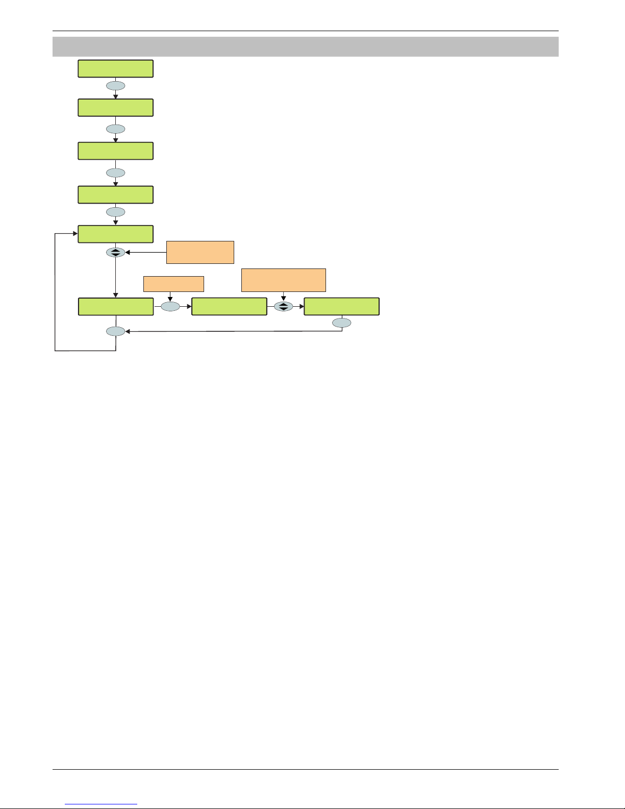
Programming the Control Panel Premier 640 Installation Manual
90 INS344
Access Profiles
Yes
No
Setup Users
Add/Edit Users
Setup Users
Access Profiles
Access Profile01
01:<N1:K1.......
YES to Select:Setup Users
Yes
Access Profile10
10:<N2:K.2......
Yes
Access Profile10
10:>N2:K.2......
Use to Alter the Network
shown & Keys 1-8 to toggle
specific door controls on or off
U
No
Press NO to edit the
Access Profile
Access Profile10
10:>N3:K.2..4...
Yes
No
Setup Users
User Profiles
Use or enter
Access Profile number
(ie 10=Access Profile 10)
U
An Access Profile determines the doors that a user assigned to the specified Access Profile can control. An Access Profile can
be assigned to any number of users.
Once an Access Profile has been assigned, any subsequent changes will automatically be applied to all users assigned to the
profile.
Page 91

Premier 640 Installation Manual Programming the Control Panel
INS344 91
5.9 Engineer Utilities
View Event Log
YES to Select:Engineer Utils
Yes
Engineer Utils
View Event Log
Yes
Use the SCROLL key to move up and
down through the log. DOWN moves to
the previous event (backwards in time)
and UP moves forwards again. Or
use one of the otkeysavailable h
PROG. START
12:28.04 06/03
Press AREA. to toggle the
display between the Area
information and the time/date
Code 01 David
12:28.04 06/03
Area
1
1=Event,2=Alarm
3=Mandatory Log
Use keys 1, 2 or 3 to select the
System, Alarm or Madatory
log i.e. 1= System Log
Menu
Press CHIME. to find any
preceding events relating to
the displayed event i.e.
User codes being entered
Code 01 David
Area: A.......
Code 12 John
12:28.04 06/03
Part
Press PART to display any
programmed zone text etc.
Code 01 David
Area: A.......
Chime
The control panel has three Event Logs, which are time and
date stamped. The first log which is a system log, records all
events that occur on the system, i.e. Users entering their
codes to arm or disarm areas, alarm events, failures to arm
etc.
The second log which is an alarm log, only records alarm
events that occur on the system.
The third log is the Mandatory Event log which records only
events defined as ‘mandatory’ by EN50131.
The System Log records the last 5000 events.
The Alarm Log records the last 32 alarm events.
The Mandatory Log records the last 500 mandatory events.
Event Log Hotkeys
When viewing the system log there are 8 hotkeys available.
These hotkeys allow certain events to be found easier without
the need for searching.
The following hotkeys are available:
!
= Priority Alarms (PA, Fire etc.)
"
= Normal Alarms (Guard, 24hr, Entry/Exit etc.)
#
= Opens and Closings (Arm, Disarm etc.)
$
= Omits and Reinstates (Zone Omits etc.)
'
= Maintenance (System Tests, Engineer Program etc.)
(
= Tampers (Zone, Bell, Aux etc.)
)
= Test Calls (Communicator Active, successful etc.)
*
= Entry/Exit (Entry and Exit Procedures)
&
= User Codes (User codes being used)
Page 92

Programming the Control Panel Premier 640 Installation Manual
92 INS344
Event Log Descriptions
Log Event Description
### ARM FAILED An exit fault from Zone ### has caused the system to fail to arm
### Flt Alarm Zone ### has detected a Fault condition
### Mask Alarm Zone ### has detected a Mask condition
### Test Failed Zone ### has activated whilst it has been on soak test
### Tested OK Zone ### has activated during the walk test
#,# RESET AREAS - Area have been reset using keypad #,# following an Intruder alarm
AC Off Alarm The control panel has detected an AC Mains failure
ALARM ABORT An Open After Alarm-Abort has occurred for area ?
ALARM Active An Intruder alarm signal has been activated for area ?
Anti-Code Reset A reset has been performed using the Anti-code reset procedure
AREA Armed Area ? has been armed
AREA Disarmed Area ? has been disarmed
ARMED WITH L/F The system has been armed with a Line Fault condition present
ARMING FAILED A Exit Error-Arm Fail has occurred on area ?
ARMING SUITE # Area Arm Suite # was used to arm the system
ATS FAILED The Comunicator has failed to report to the Alarm Receiving Centre
ATS FLT Alarm There is a problem with the telephone line
AUTO TEST CALL An Automatic test call has been initiated
AUX #,# Tamper An Auxiliary Tamper input from device #,# has been activated
AV CLEARED by ## The Audio Verification unit has been cleared down by user ##
BELL #,# Tamper A Bell Tamper input from device #,# has been activated
BELL Active The Bell output has been activated for area ?
BELL FUSE Alarm The control panel Bell Fuse has failed
BOX LID Tamper The control panel lid has been removed causing a Tamper alarm
CODE #,# Tamper Too many invalid key presses have caused a tamper alarm from keypad #,#
Com??? Line Fault The Com300, 2400 or ISDN has detected a line fault
COM PORT Alarm A com port has generated an alarm
CONFIRMED ALARM Two or more detectors have activated, resulting in a confirmed alarm condition
CORRUPT EVENT No event has been stored in memory
CROSS ### Alarm A Verified Cross Zone (Beam Pair) Alarm has occurred from zone ###
DATA CHANGED Programming data has been changed
DATE CHANGED The control panel Time has been changed
DEFAULTS LOADED The factory default values have been loaded into memory
DEFERRED The arming mode was deferred for area ?
DOOR #,# Door #,# has been opened by a user with Door Control
DOWNLOAD START An Upload/Download has been initiated
DOWNLOAD END The Upload/Download has finished
DURESS User ## has entered a Duress Code at a keypad
Engineer Reset A reset has been performed using an Engineers code
ENTRY Area ## The Entry mode has been started for area ?
EXIT Area ## The Exit mode has been started for area ?
EXP #,# Reset A reset has been performed using the input on expander #,# (programmed as reset)
EXP #,# Line Fault The Input on expander #,# (programmed as line fault) has been activated
EXP #,# LOST Expander ## has been lost from the network
EXP #,# Tamper The cover of expander #,# has been removed
F_PA ## A Panic Alarm from a Radio FOB has been generated
Fault Override The system has been armed with a Fault condition present by a user
FIRE ### Active Zone ### (programmed as Fire Alarm) has caused an alarm
FIRE ### Tamper Zone ### (programmed as Fire Alarm) has caused an Tamper alarm
FIRST KNOCK ### Zone ### (which is programmed as double knock) has activated for the first time
FUSE #,# Alarm The Auxiliary 12V Fuse in device #,# has failed
GSM MODULE LOST The GSM Module has lost communications with the control panel
iD Loop# Tamper There is a short circuit on iD loop # on the iD expander
Key switch Reset A reset has been performed using a key switch
KSW ### Disarmed A Keyswitch zone type has been activated (zone number ###)
LOG ALERT 80% of the Event Log has filled (since the last Upload/Download)
LOG CLEARED The event log has been erased
LOW BAT Alarm The control panel has registered a low battery condition
LOW V #,# Alarm Expander #,# has detected that’s its supply voltage is low
Page 93

Premier 640 Installation Manual Programming the Control Panel
INS344 93
Log Event Description
MANUAL TEST CALL A Manual test call has been initiated
MIC ## TESTED Microphone ## on the Audio Verification Module has been tested
No RF Signal ### The Wireless receiver has detected a signal loss from zone ###
Panel Line Fault The control panel line fault input has been activated
PART Armed Area ? has been Part Armed
PART 1 Armed Part Arm 1 has been selected
PART 2 Armed Part Arm 2 has been selected
PART 3 Armed Part Arm 3 has been selected
POWERED UP System Power Up (without doing a factory restart)
PROG. END The Engineer has logged out of the Programming menu
PROG. START An Engineer code has been entered
PSUac ## Alarm An expander input programmed as PSU Monitor control panel has detected an AC Mains failure
PSUbat## Alarm An expander input programmed as PSU Monitor control panel has detected a Battery fault
PSUvol## Alarm An expander input programmed as PSU Monitor control panel has detected a 12V Output failure
PSUTam## Alarm An expander input programmed as PSU Monitor control panel has detected a Tamper condition
QUICK Armed Quick Arm from keypad #,#
R/Bat ## Alarm The Wireless receiver has detected a low battery signal from device ##
Radio Jammed The Wireless receiver has detected an attempt to jam its radio signal
RADIO PAD LOST The Radio-Pad has no signal or has lost communications with the control panel
REARM LOCK ### Zone ### has locked out after reaching its re-arm limit (after causing an alarm)
RECENT Armed Area ? has been armed recently
Redcare Line Fault The Redcare has detected a line fault
REMOTE Armed Area ? was armed using the Wintex UDL software
REMOTE Disarmed Area ? was disarmed using the Wintex UDL software
Remote PC Reset A reset has been performed by the remote download PC
Remote Reset A reset has been performed using the ‘Remote Reset’ input
Redcare Reset A reset has been performed by the Redcare
RKP #,# MEDICAL A Medical alarm (7 & 9) has occurred from keypad number #,#
RKP #.# FIRE A Fire alarm (4 & 6) has occurred from keypad number #,#
RKP #,# AUD PA An Audible PA alarm (1 & 3) has occurred from keypad number #,#
RKP #,# SIL PA A Silent PA alarm (1 & 3) has occurred from keypad number #,#
RKP #,# Tamper The cover of keypad #,# has been removed
RKP #,# LOST Keypad ## has been lost from the network
RKP LOCKED #,# Keypad #,# has been locked out from too many invalid key presses
TAG ## User ## has presented their Prox TAG
TESTED ### Zone ### has been tested
TEST FAIL ###) Zone ### has failed its Soak test
TIME Armed Area ? was armed automatically using one of the control timers
TIME CHANGED The control panel Date has been changed
TIME Disarmed Area ? was disarmed automatically using one of the control timers
TUBE ### Alarm Zone ### (programmed as Tube Key) has caused an alarm
USER ## User ## has entered their code
USER CODE CHANGED A User code has been altered or added
USER CODE DELETED A User code has been deleted
User Reset A reset has been performed using a User code
WALK Tst start The Walk Test mode has been initiated
Zone ### Alarm Zone ### has been activated
Zone ### Tamper Zone ### has caused a Tamper alarm
Zone ### Restore Zone ### has restored to its normal condition
Zone ### Omitted Zone ### has been omitted
Zone ### Un-Omit Zone ### has been reinstated
Zone ### Test Start Zone ### has been put on test
Zone ### Test End Zone ### has been removed from test
Page 94
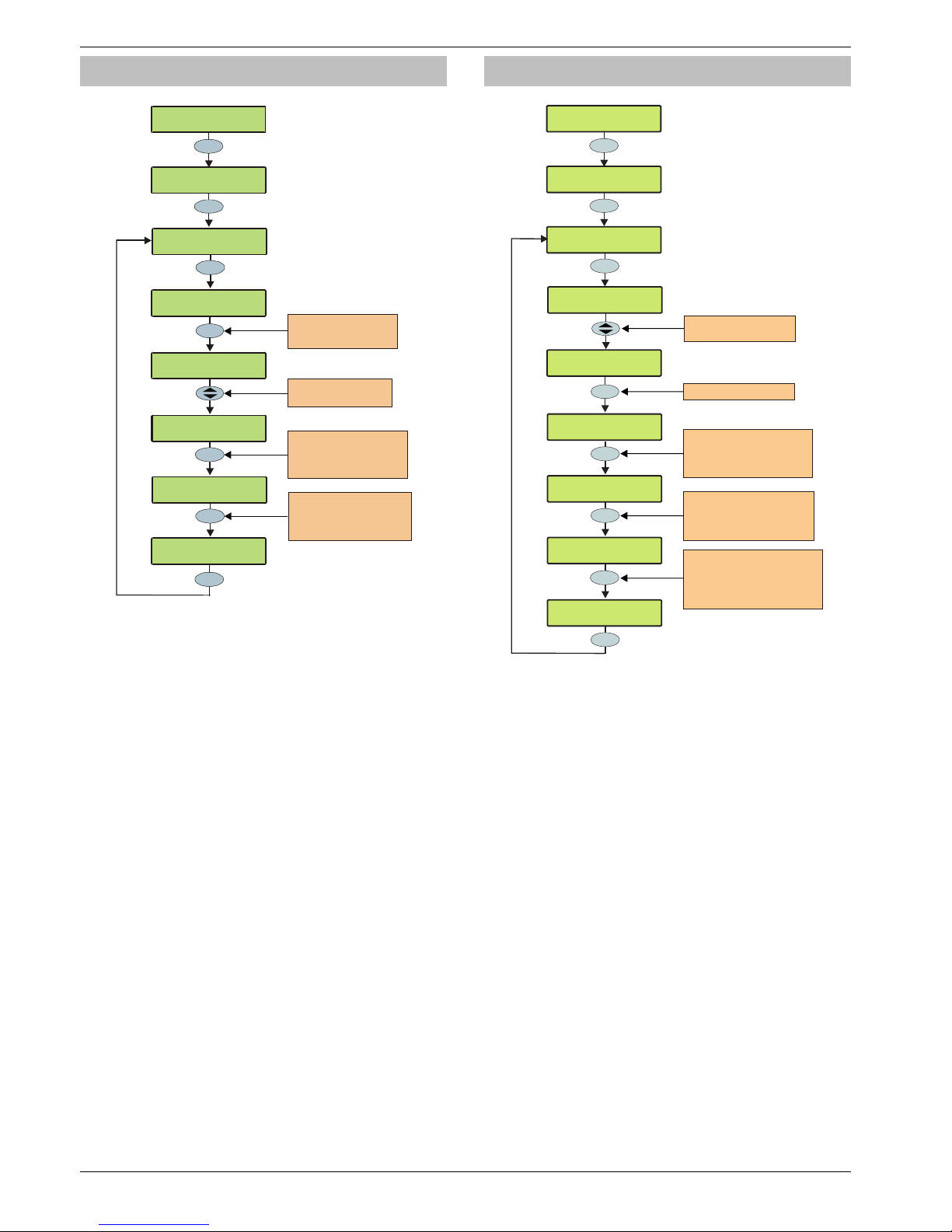
Programming the Control Panel Premier 640 Installation Manual
94 INS344
Do Bell Test
Yes
78958$$)!\:5-<
C0!N$--!"$<:
I#<K!>73!:0!:$<:
N$--!C5<(E-$D
Menu
3
def
I#<K!>73!:0!:$<:
C595!W
!!MMMMMMMM
Press YES to test ALL
channels or use keys 0 - 8
to select individual channels
e.g. 3 = Channel 3
I#<K!>73!:0!:$<:
C595!W!!MMMMMMMM
3
def
I#<K!>73!:0!:$<:
C595!W
!!MMMMMMMM
Press YES again to clear ALL
channels or use key s 0 - 8
to clear individual ch annels
e.g. 3 = Channel 3
Use the SCROLL key to
select the required test
Yes
2
abc
>73!:0!3$-$6:Z[
78958$$)!\:5-<
78958$$)!\:5-<
T5$J!74$8:!?09
I#<K!>73!:0!:$<:
N$--!5
<!!!!!
WHBB
Press OMIT to invoke the
Engineers Hold Off mode
of a Texecom Bellbox
Omit
This option allows Allows the Bell, Speaker and various
control panel outputs to be tested.
The following outputs can be individually tested:
Test Bell The Bell output
Test Strobe The Strobe output
Test Speaker The Speaker output
Test Digi The Hardwired digicom outputs
Test Panel The panel outputs
Test RedCARE The plug on RedCARE outputs
Test Com???? The plug on digi outputs
LCD Display The LCD keypad display
User Outputs Any outputs that have the ‘User Test’
attribute (see page 66 for details).
!
Pressing OMIT at the Bell or Strobe Test will cause the
Strobe output to pulse 3 times, invoking Engineers
Hold Off mode if a Texecom bell box is connected.
Do Walk Test
Yes
Engineer Utils
Do walk test
Yes
1
Walk test Areas>
* * Area 01 * *
* NONE *
Yes
Press YES to walk test
Menu
???
Chime
Press CHIME to select:
Chime Once then lockout zone
No Chime at all
Chime on every activation
or
Zones that need
testing are :
Zone 001 >007
Front Door
Press AREA. to toggle the
display between the zones
that have been tested and
the zones that still need testing
Area
To view zones that have not
activated recently, e
i.e. 007 will show zones that have
not activated in the last 7 days
nter the
number of days required
Zone 005
Lounge PIR
YES to Select:Engineer Utils
Engineer Utils
View Event Log
Walk test Areas>
* * Area 01 * *
Use Key or enter the
Area number to walk test
U
Any of the zones on the system can be walk tested to ensure
that they operate correctly. A walk test can only be performed
when the system or area is disarmed.
!
Once a zone has been activated it will not generate a
chime tone again. If however the
2
key is pressed, a
zone will chime every time it is activated.
The Walk test menu also includes a last activation log that
can be recalled when doing a walk test. This log shows zones
that have NOT been activated over a period of days.
Pressing the
6
key will firstly show the zones that still need
testing, pressing the 6 key a second time will display the
zones that have not been activated that day, to view zones
that have not been activated for 3 days, type in 003 the
maximum number of days that can be recalled is 255,
pressing the
6
key a third time will revert back to the
standard walk test display.
Page 95
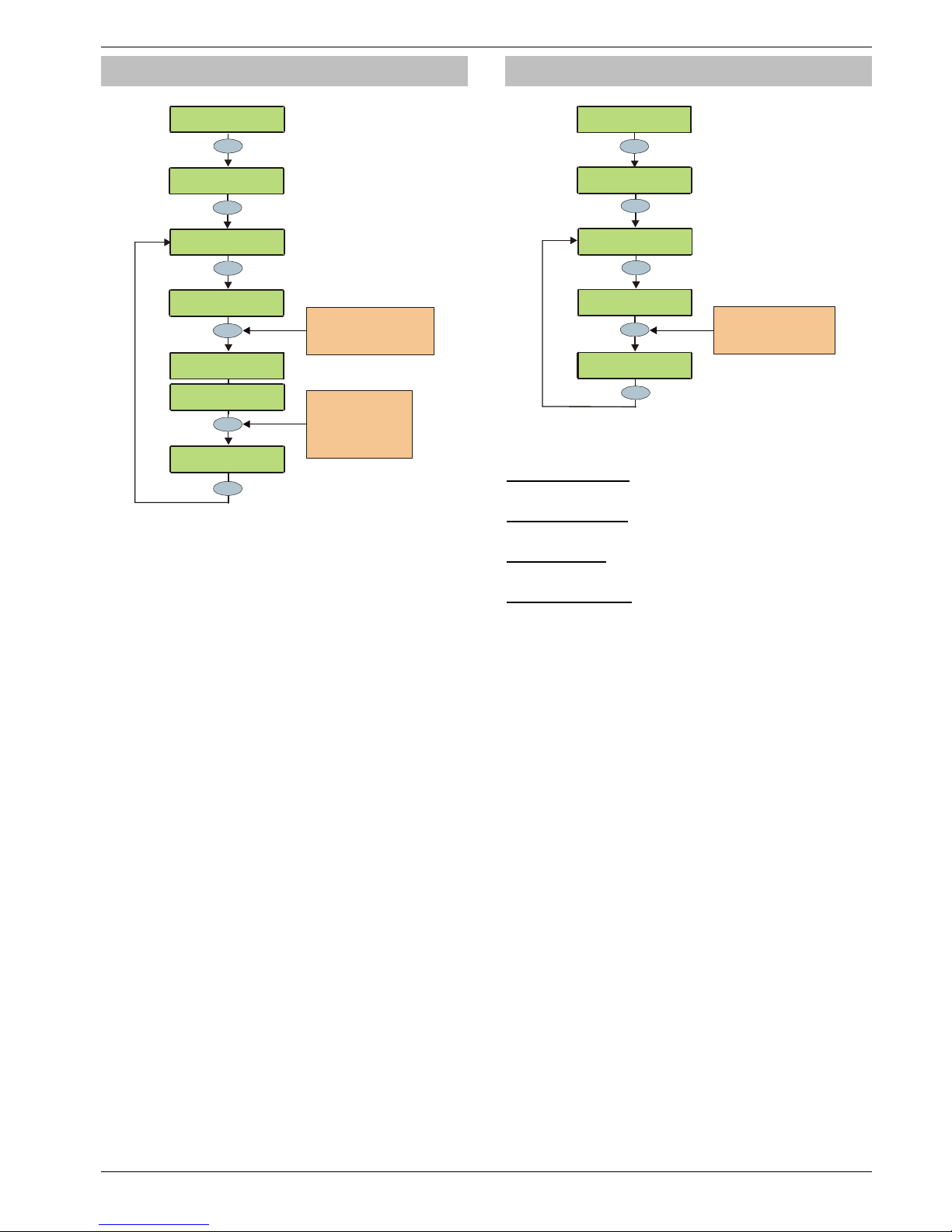
Premier 640 Installation Manual Programming the Control Panel
INS344 95
View Zone Status
>73!:0!3$-$6:Z[
78958$$)!\:5-<
Yes
3
def
Omit
Use keys 0 - 9 to enter the
required zone number or
use th e SCR OLL k ey to s earch
e.g. 064 = Zone 64
???
^
08$!
%%+!I
(8$-!
+
3
$6#)$!!!!!!!
*G*
^
08$
R%&g!L+S7kSX
^08$!C5<(E-$D
Menu
To disable the zone,
Press OMIT.
To make the zone Chime,
Press CHIME
To view the zone text,
Press AREA
^08$!%&g!L+S7kSX
3$6#)$!!!!!!!*G*
^08$!%&g!L+S7kSX
.6:54$!!!!!!!&Gc
Yes
78958$$)!\:5-<
T5$J!74$8:!?09
78958$$)!\:5-<
T5$J!^08$!3:(:#<
This option can be used to view the status of any zone on the
system to see whether it is ‘Active’, ‘Secure’, ‘Tampered’ or
‘Shorted’. The selected zone can also be temporarily disabled
(zone and tamper) to allow the zone to be worked on or made
to chime every time it is activated.
!
When leaving the View Zone Status menu, all zones
will be automatically reinstated and cleared of Chime.
Do System Tests
Yes
78958$$)!\:5-<
3=<:$/!"$<:<
C0!=0#!J(8:!:0
T5$J!3=<1!3:(:#<
4
ghi
3=<!T0-:(9$W+f1k
3=<!,#))$8:W%&Xc
Use keys 1 - 4 to select
an opti on or use the
SCROLL k ey to search
e.g. YES = View Sys. Status
Yes
Menu
Yes
>73!:0!3$-$6:Z[
78958$$)!\:5-<
78958$$)!\:5-<
T5$J!74$8:!?09
This option allows various control panel features to be tested
or reviewed.
1 - View Sys. Status
Allows the system voltage and current to be viewed.
2 - View Batt Status
Allows the battery voltage and charging status to be viewed.
3 - Test Outputs
Allows the Bell, Speaker and system outputs to be tested.
4 - View Version No.
This option allows the control panel software version and
serial number to be viewed.
Page 96
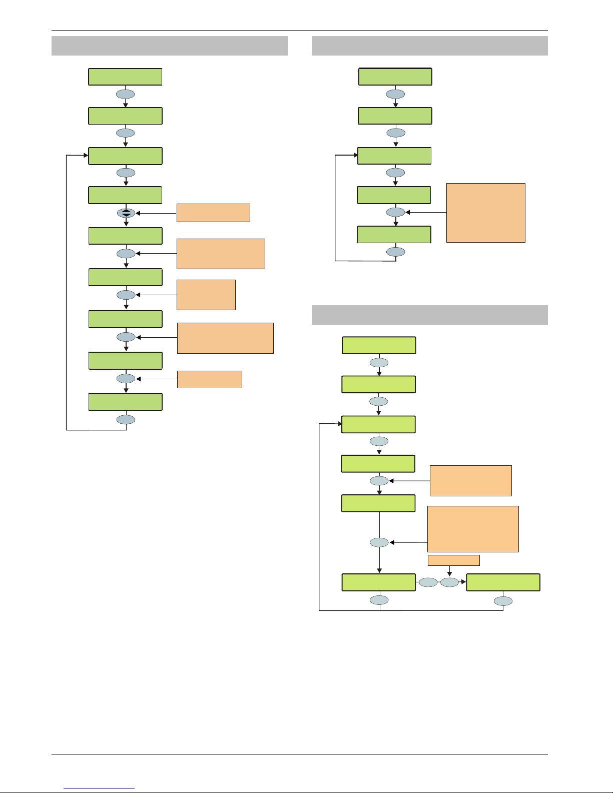
Programming the Control Panel Premier 640 Installation Manual
96 INS344
Confirm Devices
Yes
78958$$)!\:5-<
,08B5)/!C$456$<
5
jkl
Menu
L$:!;QIW+
1111111
!
+!!7POW
11111111
Press YES if the number
of devices fitted is correct.
A
n ‘X’ on th e displa y indica tes
that a device was previous fitted
L$:!;QIW+*f11111
!*!!7POW+1111111
Yes
L$:!;QIW+*f
11111
!
*!!7POW+
1111111
Use the SCROLL key to
select the required network
A
rea
L$:!7
))0)<W!
%%%%
!*!!?(<:!;QIW!+
Press AREA to view the network
errors (the total number of errors
on the network and the last de vice
to cause an error is being displayed)
Reset
Press RESET to
clear the network errors
L$:!7))0)<W!%%Ag
!*!!?(<:!;QIW!+
Press YES to c onfirm
the devices fitted
(a confirmation tone
will be heard)
I)$<<!>73!(9(58
:0!,08B5)/1
Yes
Yes
>73!:0!3$-$6:Z[
78958$$)!\:5-<
78958$$)!\:5-<
T5$J!74$8:!?09
This option allows the networks to be viewed to see what
devices are connected and whether there are any problems.
Whenever new devices are added to the system, the
networks must be checked and confirmed.
!
If any devices are removed from the system, the networks
must be rechecked and reconfirmed.
An ‘X’ on the display indicates that device that was
previous fitted is no longer being seen by the control
panel.
View RKP Status
Yes
??
7895
8$$)!
\:5-
<
T5$J!;QI!3:(:#<
6
mno
Menu
L+S;+!!^+
d1!^*d1
!!MLH"!25::$DM
Use keys 1 - 8 to select a
keypad and press 0 to
toggle between networ ks e.g.
0, 3 = Network 2, Keypad 3
Press AREA to display errors
Press NO to test output
Press OMIT to test sounder
L*S;f!!^+de!^*de
"(/Ode!!H#:O#:d%
Yes
>73!:0!3$-$6:Z[
78958$$)!\:5-<
78958$$)!\:5-<
T5$J!74$8:!?09
This option allows the status of the keypad, the zones and the
output to be viewed.
View Exp. Status
Yes
??
Engineer Utils
View Exp. Status
7 pqrs
Press AREA to change between
zones/voltage/outputs/errors
(and PSU status if PSU200XP fitted)
Press CHIME to test zones
Press OMIT to test sounder
Press 1 - 8 to test outputs
N1,E1 12345678
*Not Fitted*
Use keys 1 - 8 to select an
expander and press 0 to
toggle between networks e.g.
0 , 2 = Network 2, Expander 2
N2,E2 12345678
Zones HHHHHHHH
Area
Menu
N2,E2 12345678
Outputs ........
Yes
YES to Select:Engineer Utils
Engineer Utils
View Event Log
N2,E2-PSU V:13.5
I:0656mA: S:.....
Area Area
Menu
If PSU200XP Fitted
This option allows the status of the expander, the zones,
voltage/inputs and outputs and any monitored power supply
to be viewed.
!
The PSU status shows the following codes:.
A: AC Mains Fail
1: Battery 1 Fault
2: Battery 2 Fault
F: Mains Fuse Blown
T: PSU Box Tamper
Page 97
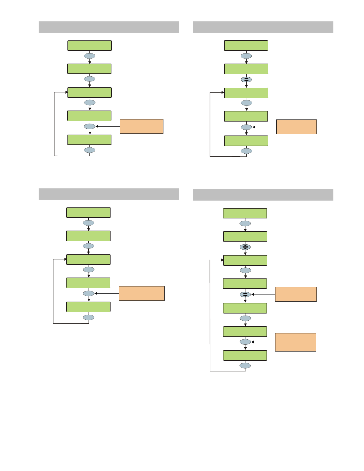
Premier 640 Installation Manual Programming the Control Panel
INS344 97
Set System Time
Yes
78958$$)!\:5-<
3$:!3=<:
$/!"5/$
`
8
tuv
Yes
78:
$)!8$J!:5/$!
W
!!!!!%%Z%%
Use keys 0 - 9 to enter the
new time (24-Hour format)
e.g. 1645 = 4:45 pm
????
78:
$)!8$J!:5/$!
W
!!!!!+&ZgA
Yes
>73!:0!3$-$6:Z[
78958$$)!\:5-<
78958$$)!\:5-<
T5$J!74$8:!?09
The control panel has a real time clock that is used to date
and time stamp events that are recorded within the system
log. The option allows you to set the control panel time.
Set System Date
Yes
78958$$)!\:5-<
3$:!3=<:
$/!C(:$
`
9
wxyz
78:
$)!8$J!D(:$!
W
!!!!%+]%+]%+
Yes
Use keys 0 - 9 to enter the
new date DD/MM/YY
e.g. 030501 = 3rd May 2001
??????
78:
$)!8$J!D(:$!
W
!!!!%f]%A]%+
Yes
>73!:0!3$-$6:Z[
78958$$)!\:5-<
78958$$)!\:5-<
T5$J!74$8:!?09
The control panel has a real time clock that is used to date
and time stamp events that are recorded within the system
log. The option allows you to set the control panel date.
Change Eng. Code
>73!:0!3$-$6:Z[
78958$$)!\:5-<
Yes
78958$$)!\:5-<
,K(89$!7891!,0D$
Yes
78:$)!L$J!,0D$!W
!!!!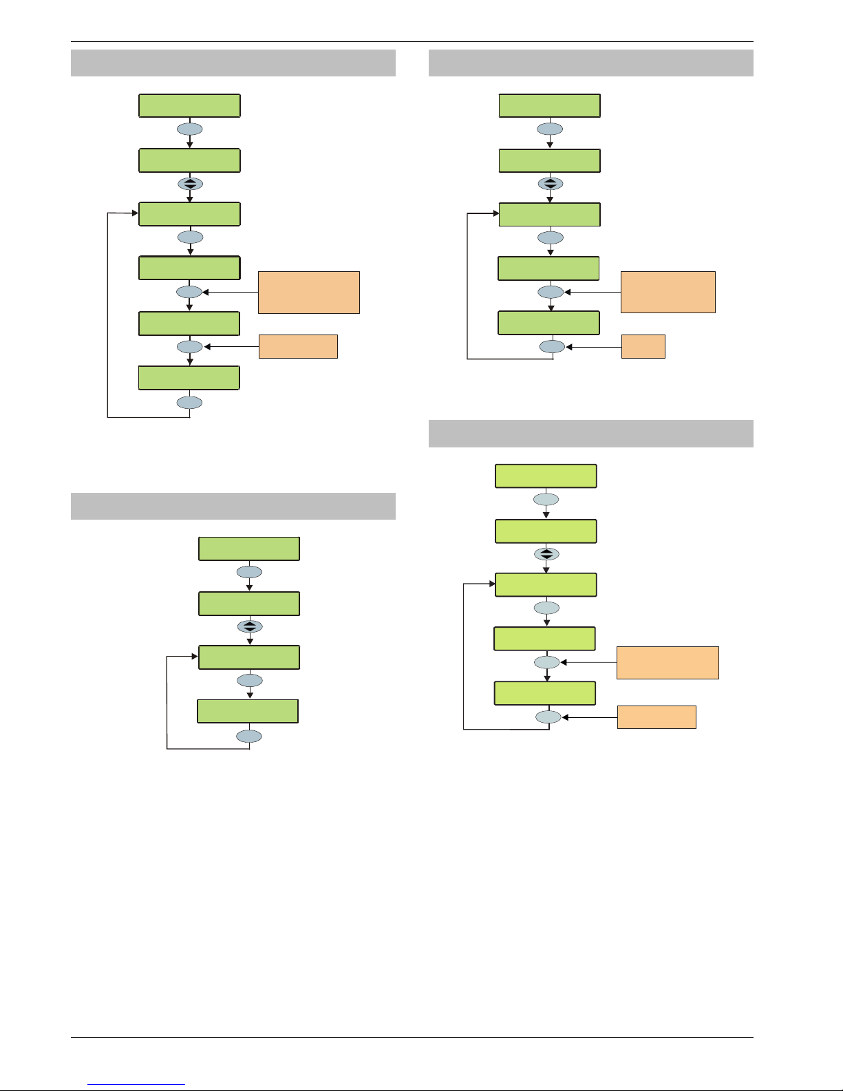
Programming the Control Panel Premier 640 Installation Manual
98 INS344
Default NVM Data
>73!:0!3$-$6:Z[
78958$$)!\:5-<
Yes
Menu
78958$$)!\:5-<
C$B(#-:!LT'!C(:(
I)$<<!>73!;$<$:Z
I(8$-!H#:O#:<
3
def
Yes
3
def
I)$<<!>73!;$<$:Z
Q$=O(D!H#:O#:<
Q$=O(D!H#:O#:<
M!I-$(<$!F(5:@!M
Use keys 0 - 9 to select
an option or use the
SCROLL key to search
e.g. 3 = Keypad Outputs
Press YES to default
the option
78958$$)!\:5-<
T5$J!74$8:!?09
This option allows various parts of the NVM to be defaulted
without having to ‘Factory Default’ the system.
Location Text
>73!:0!3$-$6:
Z[
78958$$)!\:5-<
Yes
Yes
7895
8$$)!
\:5-
<
?06(:508!"$P:
L0!?
06(:508!"$P
:
!e(<!N$$8!3$:#O
Yes
7895
8$$)!
\:5-
<
T5
$J!74$8:!?0
9
This option allows the ‘Panel Location’ text that has been
programmed in ‘System Text’ to be displayed (see page 53
for programming details).
!
The display will automatically clear after 5 seconds.
Print Log Data
>73!:0!3$-$6:Z[
78958$$)!\:5-<
Yes
????
7895
8$$)!
\:5-
<
I)58:!?09!C(:
(
L#/E$)!0B!74$8:<Z
!!!!!W!%%%%
Yes
Press YES
to print
Yes
L#/E$)!0B!74$8:<Z
!!!!!W!%%A%
Enter a value or use the
SCROLL key to increase
or decrease the value
e.g. 50 = Last 50 Events
78958$$)!\:5-<
T5$J!74$8:!?09
This option allows the ‘Event Log’ to be printed to a standard
RS232 printer (see page 27 for details).
Soak Test Areas
YES to Select:Engineer Utils
Yes
??
Engineer Utils
Soak Test Areas
Soak Test Areas:
* * No Areas * *
Yes
Press YES start
Soak test
Enter Area Profile to be
tested
ie 01=Area Profile 01
Soak Test Areas:
* * Area 02 * *
Yes
Engineer Utils
View Event Log
This option allows zones with the ‘Soak Test’ attribute to be
tested by starting the ‘Zone Soak Test’ timer.
Page 99
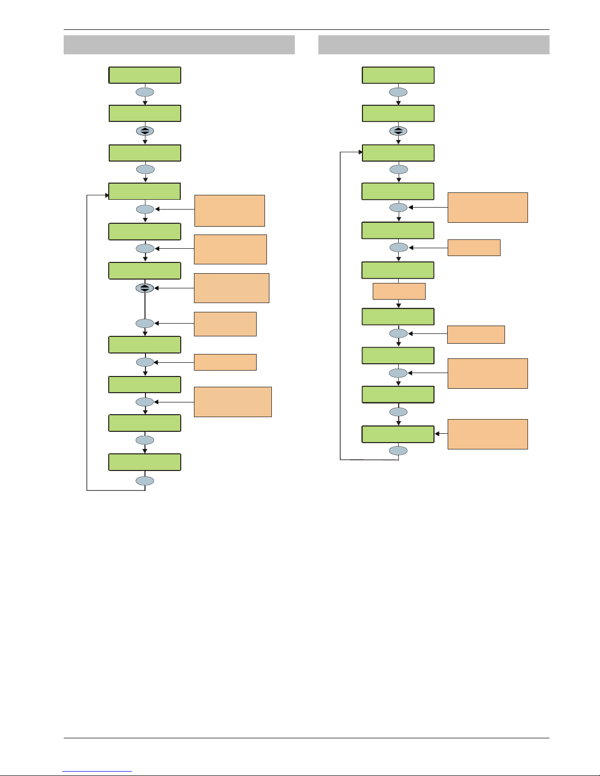
Premier 640 Installation Manual Programming the Control Panel
INS344 99
View iD Data
Yes
78958$$)!\:5-<
T5$J!5C!C(:(
Menu
+++++%+%+%+%%%++
11111111111111
+L
A
REA
5C!?
00O!+S
%+
'(OO$D!^08$!%%%
>73!:0!3$-$6:Z[
78958$$)!\:5-<
Yes
78958$$)!\:5-<
T5$J!74$8:!?09
0
????
No
Use keys 0 - 9 to enter
the zone number
5C!?
00O!+S
%+
'(OO$D!^08$W%%%
5C!?00O!+S%+
'(OO$D!^08$W%+%
5C!?00O!+S%+
'(OO$D!^08$!%+%
Press to toggle between
iD Loop and
The status of th e zones
will be displayed
0
12
%%%%+++%%++%%+++
11111111111111*L
Press to to ggle
between ormal loop scan
uick loop scan and
Biscuit Mapping
Area
N
Q
Press to edit
No
the zone mapping and
wiring options.
5C!?00O!+S%+
'(OO$D!^08$!%+%M
Press to toggle between
iD Loop and
Use keys to select the
required iD biscuit.
0
12.
Scroll
Press to toggle between
Normally Open and Normally
Closed wiring.
* = Normally Open.
Omit
Omit
Menu
Viewing the iD Data
This option allows the
60IXD
expander the iD biscuit data to
be viewed to diagnostic purposes. There are two way of
viewing the data from the expander:
Normal Scan Mode
This is the normal operation mode of the expander and the
data being displayed is the average result of 4 successive
scans of the iD loop.
Quick Scan Mode
In this mode the data being displayed is the result of each
scan of the iD loop. This mode is useful for identifying
problems with biscuits due to interference, high resistance
connections etc.
“iD” is a registered trade mark of Chloride Safety System Limited.
Configure Radio
78958$$)!\:5-<
,08B59#)$!;(D50
Menu
No
*fZ!_C*g*c%%!!HQ
3?Z%XA!!^
08$
W%%%
>73!:0!3$-$6:Z[
78958$$)!\:5-<
Yes
78958$$)!\:5-<
T5$J!74$8:!?09
*fZ!_C%%%%%%!!HQ
3?Z%%%!!^08$!%%%
Yes
???
Yes
Press YES to learn
Radio Device
*fZ!_C*g*c%%!!HQ
3?Z%XA!!^
08$
W%&g
*fZ!_C*g*c%%!!HQ
3?Z%XA!!^
08$!
%&g
??
Use keys 0 - 9 to enter the
required device number or
use th e SCR OLL ke y to s earc h
e.g. 23 = Device 23
Press NO to map the
device to a zone/user
Use keys 0 - 9 to enter the
required zone/user number or
use th e SCR OLL ke y to s earc h
e.g. 64 = Zone 64
Yes
%+Z!_C%%%%%%!!HQ
3?Z%%%!!^08$!%%%
*fZ!_C111111!".'I
.6:54(:$!C$456$
Activate the Tamper
on the Device
*fZ!_C*g*c%%!!HQ
3?Z%XA!!^
08$!
%%%
Top Line = Serial number
of device
Bottom
and status
Line = Signal strength
and zone/user number
Configuring Radio devices
Up to 100 wireless devices can be leant on to the system this
can be any combination of detectors, mag contacts and
remote FOBs.
Wireless devices can then be mapped on to the system along
with conventional detectors.
The top line on the display shows the serial number of the
device and also the status i.e. Active, Tamper etc.
The bottom line of the display shows the signal strength and
also which zone/user the device is mapped to.
!
Signal strength should be greater than 30.
The signal range is between 0 and 90.
See Radio-Plus installation manual for full details.
Page 100
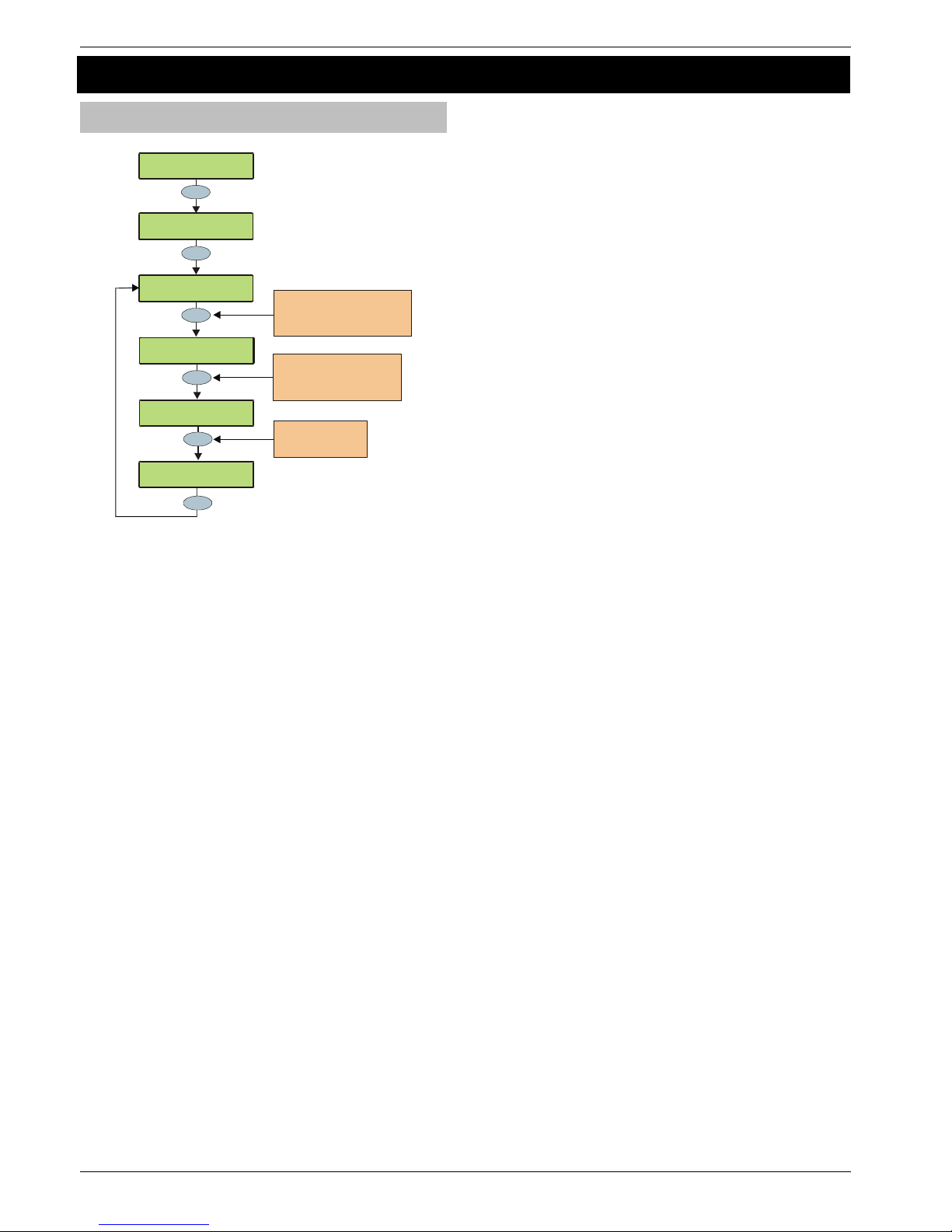
Programming the Control Panel Premier 640 Installation Manual
100 INS344
5.10 Programming Part Arms
Alter Part Arms
>73!:0!3$-$6:Z[
.-:$)!I():!.)/<
>73!:0!3$-$6:Z[
^08$!3$:#O
Part
Press NO to turn the
zone On or Off for the
selecte d Part Arm
???
No
Chime
Yes
20)!I():!.)/!+
^08$!%%+!5<!W!HL
20)!I():!.)/!*
^08$!%%+!5<!W!HL
20)!I():!.)/!*
^08$!%+%!5<!W!HL
20)!I():!.)/!*
^08$!%+%!5<!WH22
Yes
Press OMIT to select Part Arm 1
e.g. CHIME = Par t Arm 2
Press CHIME to select Part Arm 2
Press PART to select Part Arm 3
Use keys 0 - 9 to enter the
required zone number or
use the SCROLL key to search
e.g. 064 = Zone 10
Each area on the system can have up to 3 Part Arms.
When Part Arm 1, 2 or 3 is selected, pre-programmed zones
are omitted to allow access to certain parts of the building.
 Loading...