

Page 1

MSP-EXPCC430RFx Experimenter Kit
ECCN 5A002A1A
User's Guide
Literature Number: SLAU460
November 2012
Page 2

Contents
1 MSP-EXPCC430RFx Experimenter Kit Overview ...................................................................... 4
1.1 Overview .................................................................................................................. 4
1.2 Kit Contents .............................................................................................................. 8
2 Getting Started With the MSP-EXPCC430RFx Experimenter Kit ................................................ 8
2.1 Hardware Preparation .................................................................................................. 8
2.2 Software Preparation ................................................................................................... 9
2.3 MSP-EXPCC430RFx User Experience ............................................................................. 10
2.4 MSP-EXPCC430RFx Firmware Applications ...................................................................... 10
2.5 CC430 Wireless Network GUI ........................................................................................ 11
3 MSP-EXPCC430RFx Experimenter Kit Hardware .................................................................... 12
3.1 MSP-EXP430F6137Rx Hardware Description ..................................................................... 12
3.2 MSP-EXP430F5137Rx Hardware Description ..................................................................... 12
3.3 Schematics ............................................................................................................. 13
3.4 PCB Layout ............................................................................................................. 17
4 MSP-EXPCC430RFx Experimenter Kit Firmware .................................................................... 19
4.1 Import Project in Code Composer Studio ........................................................................... 19
4.2 Open Project in IAR Embedded Workbench ....................................................................... 19
4.3 SimpliciTI™ RF Protocol .............................................................................................. 19
4.4 SimpliciTI Configuration for the MSP-EXPCC430RFx User Experience ....................................... 19
4.5 5xx/6xx Core Libraries ................................................................................................ 20
5 MSP-EXPCC430RFx Experimenter Kit Software ..................................................................... 20
5.1 Requirements ........................................................................................................... 20
6 References ....................................................................................................................... 20
7 Bills of Materials (BOM) ...................................................................................................... 21
2
Table of Contents SLAU460–November 2012
Copyright © 2012, Texas Instruments Incorporated
Submit Documentation Feedback
Page 3

www.ti.com
1 MSP-EXPCC430RFx Experimenter Kit – MSP-EXP430F6137Rx Base Board (Front)............................ 5
2 MSP-EXPCC430RFx Experimenter Kit – MSP-EXP430F6137Rx Base Board (Back)............................ 6
3 MSP-EXPCC430RFx Experimenter Kit – MSP-EXP430F5137Rx Satellite Board (Front) ........................ 7
4 MSP-EXPCC430RFx Experimenter Kit – MSP-EXP430F5137Rx Satellite Board (Back) ........................ 7
5 MSP-EXP430F6137Rx Base Board Hardware........................................................................ 12
6 MSP-EXP430F5137Rx Satellite Board Hardware .................................................................... 12
7 MSP-EXP430F6137Rx Base Board Schematic – Page 1 ........................................................... 13
8 MSP-EXP430F6137Rx Base Board Schematic – Page 2 ........................................................... 14
9 MSP-EXP430F6137Rx Base Board Schematic – Page 3 ........................................................... 15
10 MSP-EXP430F5137Rx Satellite Board Schematic.................................................................... 16
11 MSP-EXP430F6137Rx Base Board Layout ........................................................................... 17
12 MSP-EXP430F5137Rx Satellite Board Layout........................................................................ 18
1 MSP-EXP430F6137R9 Base Board (HW-V2.1) BOM................................................................ 21
2 MSP-EXP430F5137R9T Satellite Board (HW-V2.0) BOM........................................................... 25
3 MSP-EXP430F6137R4 Base Board (HW-V2.1) BOM................................................................ 26
4 MSP-EXP430F5137R4T Satellite Board (HW-V2.0) BOM........................................................... 30
List of Figures
List of Tables
SLAU460–November 2012 List of Figures
Submit Documentation Feedback
Copyright © 2012, Texas Instruments Incorporated
3
Page 4

MSP-EXPCC430RFx Experimenter Kit User’s Guide
1 MSP-EXPCC430RFx Experimenter Kit Overview
1.1 Overview
The MSP-EXPCC430RFx Experimenter Kit is the complete sub-GHz development platform for the CC430
devices from the MSP430™ family. The kit provides two sub-GHz wireless modules: the MSPEXP430F6137Rx Base Board with the CC430F6137, and the MSP-EXP430F5137Rx Satellite Board with
the CC430F5137. Out of the box, the two modules enable demonstration of a SimpliciTI™ wireless sensor
network and take full advantage of a highly-integrated LCD and PC connection. Additionally, the kit also
enables a complete development and prototyping environment to design a wireless application.
User's Guide
SLAU460–November 2012
MSP430, SimpliciTI are trademarks of Texas Instruments.
All other trademarks are the property of their respective owners.
4
MSP-EXPCC430RFx Experimenter Kit User’s Guide SLAU460–November 2012
Copyright © 2012, Texas Instruments Incorporated
Submit Documentation Feedback
Page 5
www.ti.com
MSP-EXPCC430RFx Experimenter Kit Overview
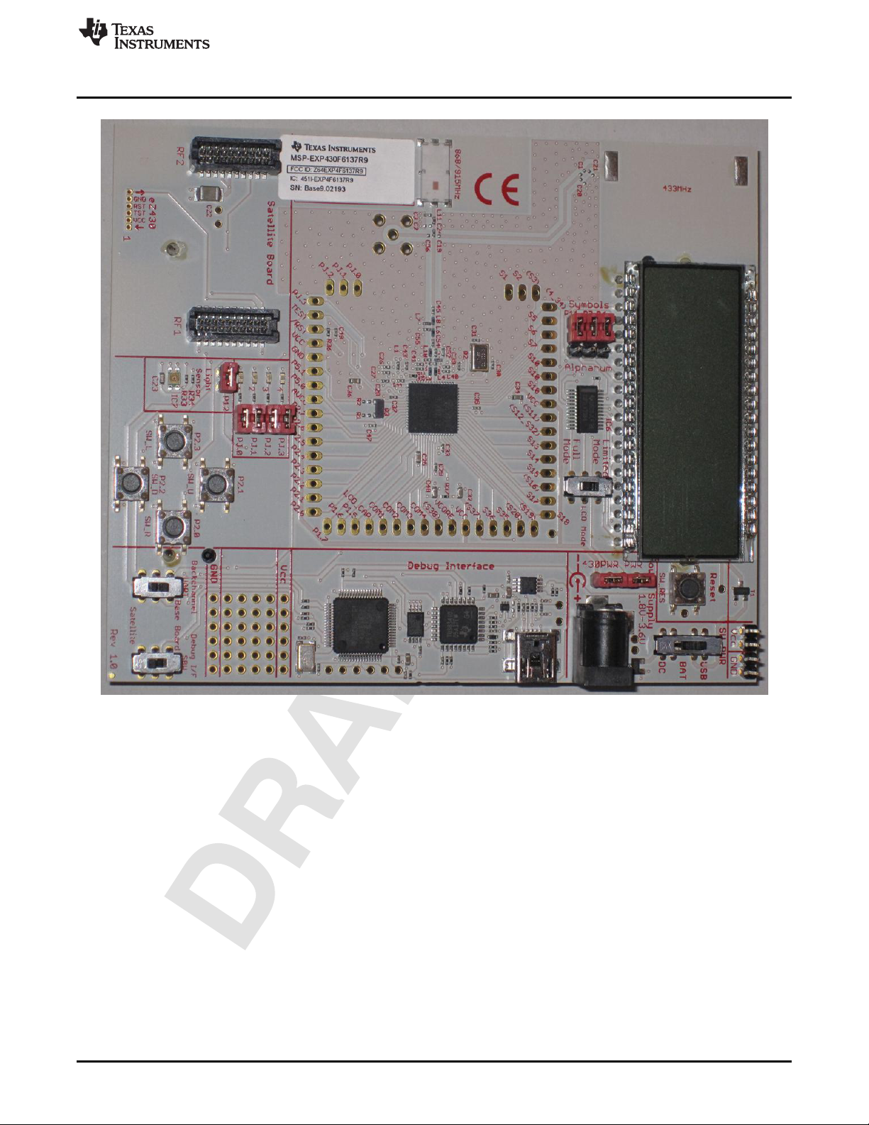
Figure 1. MSP-EXPCC430RFx Experimenter Kit – MSP-EXP430F6137Rx Base Board (Front)
SLAU460–November 2012 MSP-EXPCC430RFx Experimenter Kit User’s Guide
Submit Documentation Feedback
Copyright © 2012, Texas Instruments Incorporated
5
Page 6
MSP-EXPCC430RFx Experimenter Kit Overview
www.ti.com
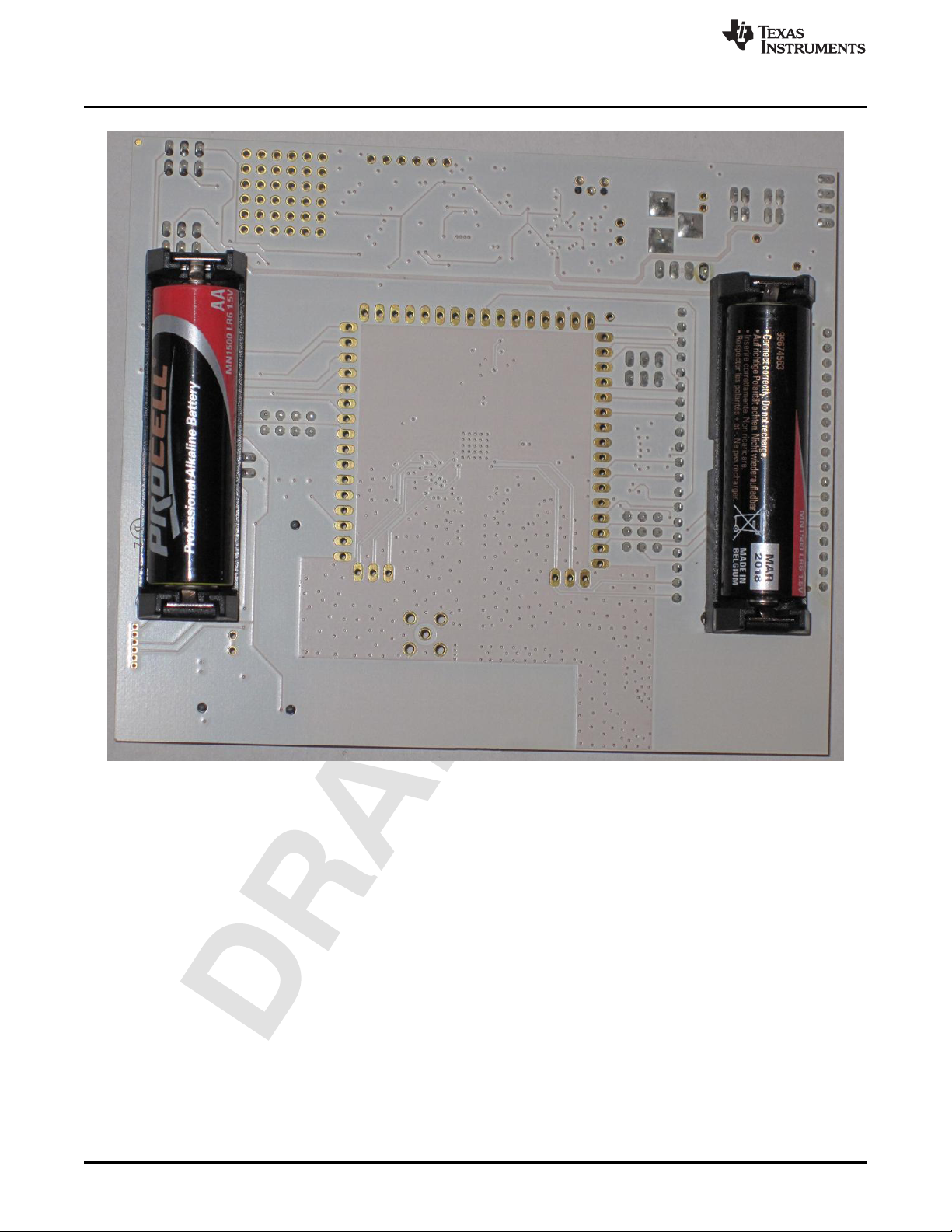
Figure 2. MSP-EXPCC430RFx Experimenter Kit – MSP-EXP430F6137Rx Base Board (Back)
6
MSP-EXPCC430RFx Experimenter Kit User’s Guide SLAU460–November 2012
Copyright © 2012, Texas Instruments Incorporated
Submit Documentation Feedback
Page 7
www.ti.com
MSP-EXPCC430RFx Experimenter Kit Overview
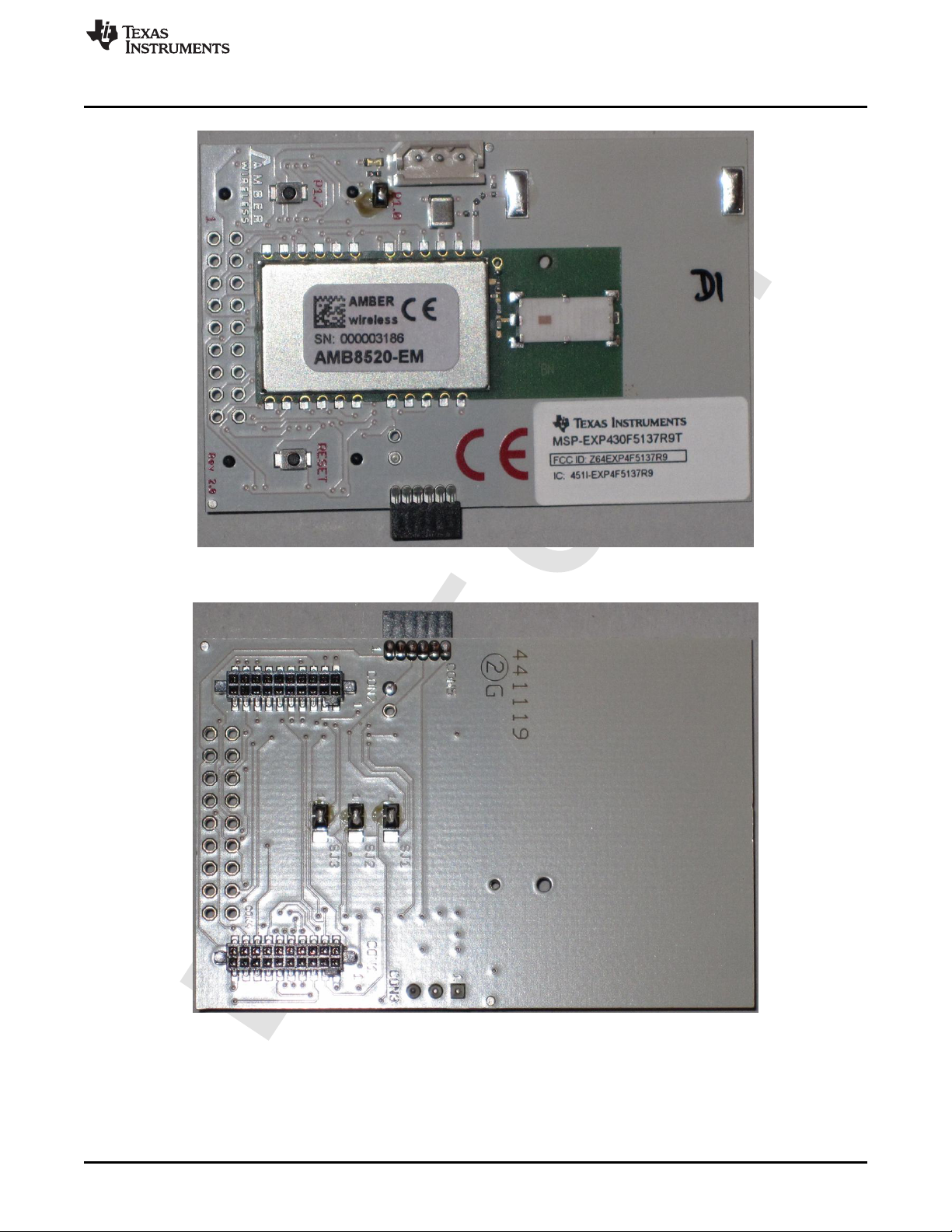
Figure 3. MSP-EXPCC430RFx Experimenter Kit – MSP-EXP430F5137Rx Satellite Board (Front)
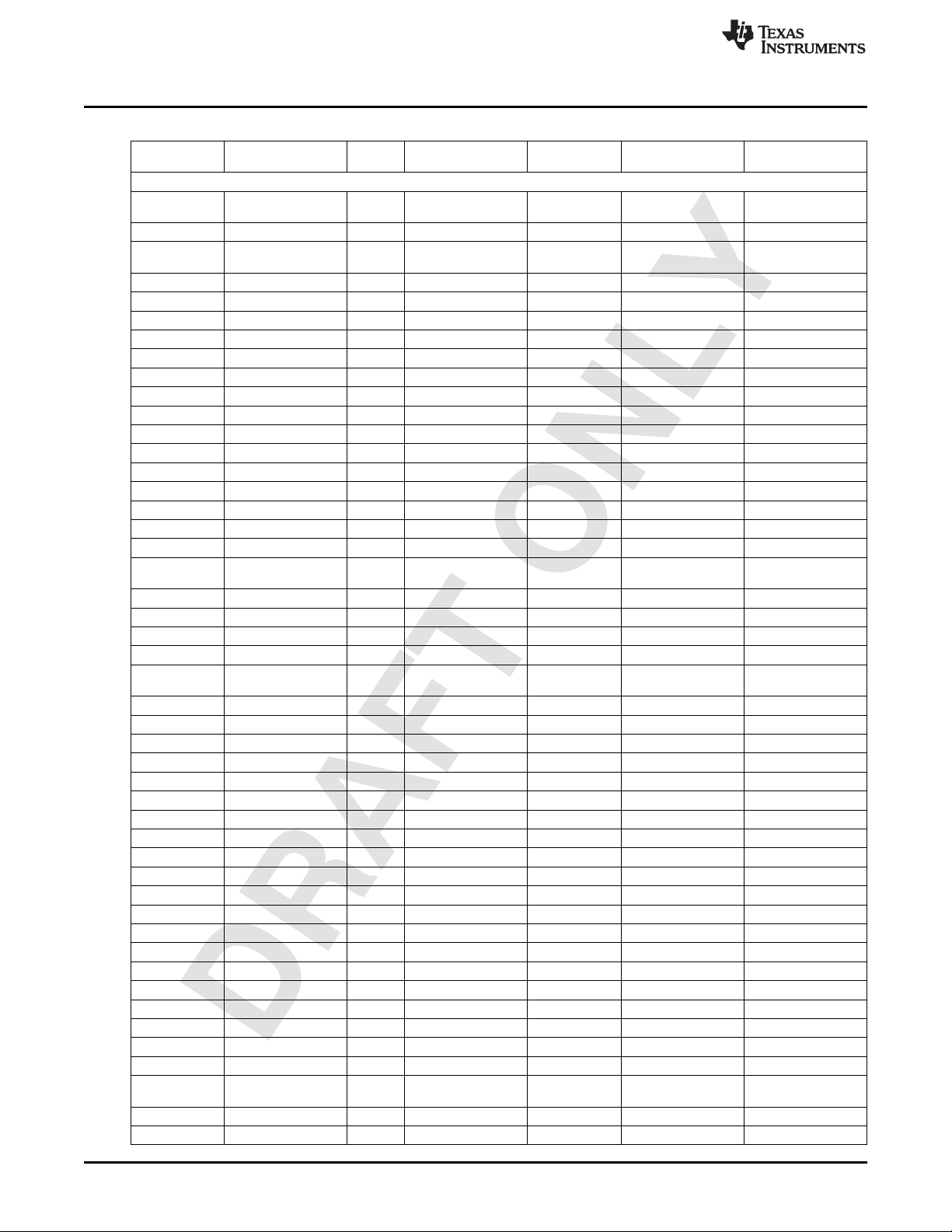
Figure 4. MSP-EXPCC430RFx Experimenter Kit – MSP-EXP430F5137Rx Satellite Board (Back)
The MSP-EXPCC430RFx Experimenter Kit is available for purchase from the TI eStore.
SLAU460–November 2012 MSP-EXPCC430RFx Experimenter Kit User’s Guide
Submit Documentation Feedback
Copyright © 2012, Texas Instruments Incorporated
7
Page 8

Getting Started With the MSP-EXPCC430RFx Experimenter Kit
The MSP-EXPCC430RFx Experimenter Kit features the RF System-on-Chip CC430 devices,
CC430F6137 with LCD driver and CC430F5137. This combination of devices enables sub-GHz RF
communication on the ultra-low-power MCU platform. The CC430 devices allow for high-performance
radio with high sensitivity and excellent blocking, while minimizing the number of external components by
integrating the solution into a single-chip MCU platform.
1.2 Kit Contents
The MSP-EXPCC430RFx Experimenter Kit includes two components:
• One MSP-EXP430F6137Rx Based Board with CC430F6137, RF front end with sub-GHz chip antenna
and options for wire antenna and SMA connector, 96-segment alphanumeric LCD, on-board integrated
debugging and programming emulator, four push buttons, four LEDs, and a light sensor.
• One MSP-EXP430F5137Rx Satellite Board with CC430F5137, RF front end with sub-GHz chip
antenna, one push button, and one LED.
The CC430 devices feature an ultralow-power 16-bit microcontroller with an integrated radio core, an
optional 96-segment LCD controller, 12-bit ADC, comparator, universal serial interface (supports UART,
SPI and I2C), 32KB flash memory, and 4KB RAM memory.
2 Getting Started With the MSP-EXPCC430RFx Experimenter Kit
The following sections describe the preparation necessary to run the user experience application demo
and to start developing applications with the MSP-EXPCC430RFx Experimenter Kit
2.1 Hardware Preparation
www.ti.com
The MSP-EXPCC430RF9 (868 MHz or 915 MHz) version of the kit is preprogrammed with firmware
operating at the 868-MHz frequency band. To comply with local regulations, ensure that the 915-MHz
version of the firmware images are programmed onto both the MSP-EXP430F6137 Base Board and the
MSP-EXP430F5137 Satellite Board before using the kits in North America (USA or Canada).
Programming of the firmware can be done using the firmware loader or the IAR or CCS software projects
included in the MSP-EXPCC430RFx User Experience Software Package (MSP-EXPCC430RFx Software
Download).
2.1.1 Program the MSP-EXP430F6137RFx Base Board
1. Set the "Debug (SBW)" switch and the "UART" switch to the "Base Board" position.
2. Set the"SW PWR" (power selector) switch to the "USB" position.
3. Connect the USB cord from the PC to the MSP-EXP430F6137RFx.
4. On the PC, browse to the folder that contains the firmware:
C:\ti\msp430\MSP-EXPCC430_UE_1_00_00_01\bin\firmware
5. Double click on the appropriate .bat file for the version of the firmware that is required (433, 868, or
915 MHz). The MSP430 Flasher tool programs the device with this firmware.
2.1.2 Program the MSP-EXP430F5137RFx Satellite Board
1. Make sure that the MSP-EXP430F5137RFx Satellite Board is connected to the Base Board.
2. Set the "Debug (SBW)" switch and the "UART" switch to the "Satellite" position.
3. Set the"SW PWR" (power selector) switch to the "USB" position.
4. Connect the USB cord from the PC to the MSP-EXP430F6137RFx.
5. On the PC, browse to the folder that contains the firmware:
C:\ti\msp430\MSP-EXPCC430_UE_1_00_00_01\bin\firmware
6. Double click on the appropriate .bat file for the version of the firmware that is required (433, 868, or
915 MHz). The MSP430 Flasher tool programs the device with this firmware.
8
MSP-EXPCC430RFx Experimenter Kit User’s Guide SLAU460–November 2012
Copyright © 2012, Texas Instruments Incorporated
Submit Documentation Feedback
Page 9

www.ti.com
Getting Started With the MSP-EXPCC430RFx Experimenter Kit
2.1.3 Prepare the MSP-EXPCC430RFx Experimenter Kit for Operation
2.1.3.1 Base Board MSP-EXP430F6137Rx
1. Select the power switch configuration to match the power supply in use (an external DC power supply,
batteries, or the USB connector).
2. If the batteries option is selected, insert the two AA batteries provided with the kit into the sockets on
the back on the MSP-EXP430F6137Rx base board. Observe the correct polarity (see the markings
inside the battery compartment).
3. If the USB power option is selected, connect the board to a PC using the included USB to mini-USB
cable. The USB connection also enables the PC GUI functionality.
2.1.3.2 Satellite Board MSP-EXP430F5137Rx
1. Insert the two AAA batteries that are provided with the kit into the provided battery pack. Observe the
correct polarity (see the markings inside the battery holder).
NOTE: If the board is powered by batteries or through the DC connector, the emulator is not
powered and keeps the connected target device in RESET. Therefore, the Debug (SBW)
selector must be set to the "Satellite" board for the User Experience software to operate.
2. Connect the included battery pack to the MSP-EXP430F5137Rx via the 3-pin connector CON3.
2.2 Software Preparation
The steps described in the following sections are not required for the MSP-EXPCC430RFx Experimenter
Kit stand-alone demo. For all other purposes that require PC software interaction, proper installation of the
hardware driver and the software is required. To develop applications, it is also necessary to install one of
the IDEs shown in the Tools and Software section of the MSP430 landing page www.ti.com/msp430. More
information on how to start developing applications on the MSP-EXPCC430RFx platform or with the
CC430 RF SoC devices can be found on the www.ti.com/msp-expcc430rfx.
All of the MSP-EXPCC430RFx User Experience firmware and software that is described in the following
sections is provided in both binary (executable) and source code forms, along with drivers and supporting
documentation. An installation package can be downloaded from MSP-EXPCC430RFx Software
Download. The same software package link and updates can also be found in the MSP-EXPCC430RFx
tool folder, http://www.ti.com/tool/msp-expcc430rfx. When this package is installed, all user experience
application demos are stored in the Software folder in the selected installation directory (the default
directory is C:\ti\msp430\), and the source code for the projects is installed to the src folder.
2.2.1 USB Driver
The USB driver must be installed for the PC to communicate with the MSP-EXP430F6137Rx based board
through USB. If this is the first time the MSP-EXP430F6137Rx based board is connected to the PC, install
the USB serial COM port driver located at [INSTALL_PATH]\USB_Driver\USB_Driver.exe.
NOTE: The USB drivers are integrated into the installer packages for the Code Composer Studio
IDE (version 5+) or IAR Embedded Workbench IDE (version 5.20+) and do not require a
second installation if one of these IDEs has already been installed.
2.2.2 Software Package Installation
Open the MSP-EXPCC430RFx Software Package to start the installation (MSP-EXPCC430RFx Software
Download). Accept the license agreement and specify the install path (the default path is C:\ti\msp430).
The installer populates the folder with the source code and binaries for the kit's User Experience firmware
and the PC GUI, the hardware design files, and the USB driver files.
SLAU460–November 2012 MSP-EXPCC430RFx Experimenter Kit User’s Guide
Submit Documentation Feedback
Copyright © 2012, Texas Instruments Incorporated
9
Page 10

Getting Started With the MSP-EXPCC430RFx Experimenter Kit
2.3 MSP-EXPCC430RFx User Experience
The MSP-EXPCC430RFx User Experience includes two projects:
1. Firmware applications that are pre-loaded on the MSP-EXP430F6137Rx Base Board and the MSPEXP430F5137Rx Satellite Board to demonstrate a stand-alone wireless network using the SimpliciTI
protocol.
2. When the Base Board is connected to the PC, the CC430 Wireless Network GUI program can be used
to enable visualization of the wireless sensor network.
2.4 MSP-EXPCC430RFx Firmware Applications
The MSP-EXPCC430RFx User Experience application forms a star network using the SimpliciTI protocol.
The Satellite Board acts as the End Device, and the Base Board acts as the Access Point. The Base
Board can connect to a PC via the USB cable and transmit information back to the CC430 Wireless
Network GUI running on the PC.
2.4.1 Access Point (AP or Hub)
The MSP-EXP430F6137Rx Base Board functions as the Access Point (also called the Hub), to create and
broadcast the star network using the SimpliciTI protocol. It allows compatible End Devices (EDs) to join
the network. The Base Board displays the status and sensor information of the devices on the network on
its LCD. The Base Board also provides its own status and sensor (temperature and light sensors)
information to the display. The Base Board captures more detailed network and device information and
provides that information to the PC GUI through the UART-USB bridge if the USB connection is enabled
between the board and the PC.
To start and operate the MSP-EXP430F6137Rx Base Board:
1. The MSP-EXP430F6137Rx Base Board displays "Access Point Up" on the LCD and starts accepting
connections from the Satellite Boards.
2. When a new ED successfully joins the network, the LCD briefly displays "Added New Device" and
resumes displaying network information.
3. When the network is active, the LCD displays the information of the AP and connected EDs. The first
digit on the LCD indicates the address of the device (a number for an ED, 'H' for the Hub or AP).
Subsequent digits show the temperature or RSSI value of the device.
4. The UP and DOWN buttons on the Base Board can be used to cycle through the device list.
5. The LEFT and DOWN buttons on the Base Board can be used to toggle the LCD to show the
temperature or the received signal strength indicator (RSSI) value from the EDs. If the AP (Hub) is
currently selected, the LCD switches between the temperature of the AP and the analog reading of the
light sensor.
www.ti.com
2.4.2 End Device (ED)
The MSP-EXP430F5137Rx Satellite Board functions as an End Device on the star network that is created
using the SimpliciTI protocol.
1. When supplied with power, the Satellite Board seeks out compatible network broadcasts from an AP
and attempts to join the network. During this phase, the on-board LED slowly toggles on and off to
indicate each attempt.
2. After it successfully joins the network, the Satellite Board periodically measures its temperature and
transmits its heartbeat message to the AP. Each transmission is indicated by the brief pulse of the
LED.
3. Additionally, the push button can be used to transmit an Alert message, which causes the AP to show
this ED's information on the LCD. The exclamation mark (!) on the LCD also briefly turns on, further
highlighting the Alert message to the user.
10
MSP-EXPCC430RFx Experimenter Kit User’s Guide SLAU460–November 2012
Copyright © 2012, Texas Instruments Incorporated
Submit Documentation Feedback
Page 11

www.ti.com
2.5 CC430 Wireless Network GUI
The included CC430 Wireless Network GUI is designed to provide more detailed information as well as
visual presentation of the network and device information. The GUI requires a PC USB connection from
the MSP-EXPF6137Rx Base Board. The Base Board captures all status and sensor information from the
devices (including the AP itself) and relays the prepared packets to the PC GUI. The GUI displays the
wireless network in the star topology, showing the connected and disconnected devices along with their
status information such as RSSI (relative distance from the AP), temperature, and remaining battery life.
Getting Started With the MSP-EXPCC430RFx Experimenter Kit
SLAU460–November 2012 MSP-EXPCC430RFx Experimenter Kit User’s Guide
Submit Documentation Feedback
Copyright © 2012, Texas Instruments Incorporated
11
Page 12

MSP-EXPCC430RFx Experimenter Kit Hardware
3 MSP-EXPCC430RFx Experimenter Kit Hardware
3.1 MSP-EXP430F6137Rx Hardware Description
www.ti.com
Figure 5. MSP-EXP430F6137Rx Base Board Hardware
3.2 MSP-EXP430F5137Rx Hardware Description
Figure 6. MSP-EXP430F5137Rx Satellite Board Hardware
12
MSP-EXPCC430RFx Experimenter Kit User’s Guide SLAU460–November 2012
Copyright © 2012, Texas Instruments Incorporated
Submit Documentation Feedback
Page 13

www.ti.com
3.3 Schematics
MSP-EXPCC430RFx Experimenter Kit Hardware
Figure 7. MSP-EXP430F6137Rx Base Board Schematic – Page 1
SLAU460–November 2012 MSP-EXPCC430RFx Experimenter Kit User’s Guide
Submit Documentation Feedback
Copyright © 2012, Texas Instruments Incorporated
13
Page 14

MSP-EXPCC430RFx Experimenter Kit Hardware
www.ti.com
Figure 8. MSP-EXP430F6137Rx Base Board Schematic – Page 2
14
MSP-EXPCC430RFx Experimenter Kit User’s Guide SLAU460–November 2012
Copyright © 2012, Texas Instruments Incorporated
Submit Documentation Feedback
Page 15

www.ti.com
MSP-EXPCC430RFx Experimenter Kit Hardware
Figure 9. MSP-EXP430F6137Rx Base Board Schematic – Page 3
SLAU460–November 2012 MSP-EXPCC430RFx Experimenter Kit User’s Guide
Submit Documentation Feedback
Copyright © 2012, Texas Instruments Incorporated
15
Page 16

MSP-EXPCC430RFx Experimenter Kit Hardware
www.ti.com
Figure 10. MSP-EXP430F5137Rx Satellite Board Schematic
16
MSP-EXPCC430RFx Experimenter Kit User’s Guide SLAU460–November 2012
Copyright © 2012, Texas Instruments Incorporated
Submit Documentation Feedback
Page 17

www.ti.com
3.4 PCB Layout
MSP-EXPCC430RFx Experimenter Kit Hardware
Figure 11. MSP-EXP430F6137Rx Base Board Layout
SLAU460–November 2012 MSP-EXPCC430RFx Experimenter Kit User’s Guide
Submit Documentation Feedback
Copyright © 2012, Texas Instruments Incorporated
17
Page 18

MSP-EXPCC430RFx Experimenter Kit Hardware
www.ti.com
18
Figure 12. MSP-EXP430F5137Rx Satellite Board Layout
MSP-EXPCC430RFx Experimenter Kit User’s Guide SLAU460–November 2012
Copyright © 2012, Texas Instruments Incorporated
Submit Documentation Feedback
Page 19

www.ti.com
4 MSP-EXPCC430RFx Experimenter Kit Firmware
This section describes the firmware applications provided with the project. Detailed information on the
project construction, the use of the 5xx/6xx Core Library, the use of the TI's SimpliciTI RF stack, and how
to set up and import the projects is included. Source code for the CC430F6137 and the CC430F5137
firmware application is installed to the [INSTALL_PATH]\src\ folder as described in Section 2.2.
4.1 Import Project in Code Composer Studio
To import the project into CCS:
1. Open CCS.
2. Select a new project workspace outside of the project folder.
3. Select Project-->Import Existing Project.
4. Browse to the [PROJECT_ROOT]\CCS folder.
5. Click Finish
NOTE: For CCS, while the project root is in the outer directory, the CCS project files are located
inside the CCS folder. To enable the portability of the project, the file macros.ini is created to
define the root. Additionally, all project code files (.c, .h) are added as linked resources with
their relative path to the project root.
4.2 Open Project in IAR Embedded Workbench
MSP-EXPCC430RFx Experimenter Kit Firmware
To open the project in IAR Embedded Workbench:
1. Open IAR.
2. Select Project → Add Existing Project
3. Browse to the [PROJECT_ROOT]\IAR folder
4. Select the project file *.ewp to open the project
4.3 SimpliciTI™ RF Protocol
The SimpliciTI protocol is a simple low-power RF network protocol designed for small RF networks. Such
networks typically contain battery-operated devices that require long battery life, low data rate, low duty
cycle, and have a limited number of nodes talking directly to each other or through an access point or
range extenders. Access point and range extenders are not required but provide extra functionality such
as store and forward messages. The SimpliciTI protocol requires minimal MCU resource requirements,
which results in low system cost.
The SimpliciTI protocol was designed for easy implementation and deployment out-of-the-box on several
TI RF platforms such as the MSP430 family of low-power MCUs and the CC1xxx, CC25xx, and CC430
transceivers and SoCs.
For more information on the SimpliciTI protocol, visit www.ti.com/simpliciti.
4.4 SimpliciTI Configuration for the MSP-EXPCC430RFx User Experience
The MSP-EXPCC430RFx User Experience application uses the SimpliciTI protocol in its star network
configuration to enable a sensor hub with the MSP-EXP430F6137Rx Base Board and multiple sensor
nodes (End Devices) with the MSP-EXP430F5137Rx Satellite Board. Minor configuration changes were
made to the stack to support CC430F6137 and CC430F5137 devices on SimpliciTI.
The SimpliciTI network is configured to accept up to 16 end devices. In the radio configuration, the
frequency settings are configured specifically for the frequency bands regulated by the geographical
locations. Specifically they are 915-MHz band for the US, 868-MHz band for Europe, and 433-MHz for
most other locations.
SLAU460–November 2012 MSP-EXPCC430RFx Experimenter Kit User’s Guide
Submit Documentation Feedback
Copyright © 2012, Texas Instruments Incorporated
19
Page 20

MSP-EXPCC430RFx Experimenter Kit Software
On the MSP-EXP430F5137Rx Satellite Board, two types of packets, heartbeat and alert, are prepared for
SimpliciTI transmissions. The MSP-EXP430F6137Rx Base Board running the AP stack is configured to
expect and process these two types of packets accordingly.
4.5 5xx/6xx Core Libraries
The CC430 devices are a member of the MSP430 5xx/6xx family devices. The 5xx/6xx family architecture
introduces several new core peripherals to enhance the device performance, optimize power consumption,
and allow for high flexibility and fine control of various aspects of the device core. These peripherals
include the Power Management Module (PMM), Unified Clock System (UCS), Port Map (PMAP), and
Flash modules. The 5xx/6xx core libraries provide a simple and efficient way of configuring and handling
these modules. The MSP-EXPCC430RFx User Experience utilizes the 5xx/6xx core libraries to properly
configure and start the CC430 core peripherals in the right sequence. The 5xx/6xx Core Libraries are
incorporated into the MSP430Ware DriverLib. More information and download links for MSP430Ware and
DriverLib can be found at http://software-
dl.ti.com/msp430/msp430_public_sw/mcu/msp430/MSP430ware/latest/index_FDS.html.
5 MSP-EXPCC430RFx Experimenter Kit Software
The MSP-EXPCC430RFx software package (MSP-EXPCC430RFx Software Download) includes the
CC430 Wireless Network GUI, which interfaces with the MSP-EXPCC430F6137Rx Base Board through
USB to display the wireless network based on the data received through the USB connection. In addition
to displaying the network topology, the GUI also offers vital information for the Access Point and the End
Devices including the supply voltage (VCC), temperature, and the End Devices' Received Signal Strength
Indicator (RSSI).
www.ti.com
5.1 Requirements
When modifying the CC430 Wireless Network GUI source code, Microsoft Visual C++ and Qt package are
required.
• Microsoft Visual C++ is part of the Microsoft Visual Studio suite, which can be downloaded at
http://www.microsoft.com/visualstudio/en-us/products/2010-editions/express.
• Qt is a cross-platform application framework provided by Nokia, which can be downloaded at
http://qt.nokia.com/downloads/.
6 References
1. MSP-EXPCC430RFx Experimenter Kit Product folder (www.ti.com/tool/msp-expcc430rfx)
2. MSP-EXPCC430RFx User Experience Software Package: MSP-EXPCC430RFx Software Download
3. CC430F6137 product folder: http://www.ti.com/product/cc430f6137
4. CC430F5137 product folder: http://www.ti.com/product/cc430f5137
5. CC430 User's Guide (SLAU259)
6. eZ430-Chronos Wiki: http://processors.wiki.ti.com/index.php/EZ430-Chronos
7. eZ430-Chronos product folder: http://www.ti.com/tool/ez430-chronos
8. MSP430 home page: http://www.ti.com/msp430
9. SimpliciTI product page folder: http://www.ti.com/simpliciti
20
MSP-EXPCC430RFx Experimenter Kit User’s Guide SLAU460–November 2012
Copyright © 2012, Texas Instruments Incorporated
Submit Documentation Feedback
Page 21

www.ti.com
7 Bills of Materials (BOM)
Table 1. MSP-EXP430F6137R9 Base Board (HW-V2.1) BOM
Part Value Toleran Package Manufacturer Details Distributor Part No.
Capacitors
C1 n.m. C0402 Johanson 500R07S2R2BV4T
C2 n.m. C0402
C3 2.2pF C0402 Johanson 500R07S2R2BV4T
C4 100nF 10% C0402
C5 1uF 10% C0603
C6 10nF 10% C0402
C7 33pF ±0,25pF C0402
C8 33pF ±0,25pF C0402
C9 22pF ±0,25pF C0402
C10 22pF ±0,25pF C0402
C11 1uF 10% C0603
C12 100nF 10% C0402
C13 100nF 10% C0402
C14 1uF 10% C0603
C15 100nF 10% C0402
C16 100nF 10% C0402
C17 100nF 10% C0402
C18 1nF 10% C0402
C19 n.m. C0402
C20 n.m. C0402
C21 n.m. C0402
C22 100uF 20% C-POLB/3528
C23 100nF 10% C0603
C24 68pF C0402
C25 10uF 20% C0603
C26 2pF ±0,25pF C0402
C27 2pF ±0,25pF C0402
C28 2pF ±0,25pF C0402
C29 470nF 10% C0402
C30 27pF ±0,25pF C0402
C31 27pF ±0,25pF C0402
C32 10uF 10% C0603
C33 100nF 10% C0402
C34 10uF 20% C0603
C35 100nF 10% C0402
C36 10uF 20% C0603
C37 100nF 10% C0402
C38 100nF 10% C0402
C39 2pF ±0,25pF C0402
C40 100nF 10% C0402
C41 2pF ±0,25pF C0402
C42 100nF 10% C0402
C43 100nF 10% C0402
C44 100nF 10% C0402
C45 1.5pF C0402
C47 100nF 10% C0402
C48 10uF 20% C0603
Bills of Materials (BOM)
ce
Technology
Technology
SLAU460–November 2012 MSP-EXPCC430RFx Experimenter Kit User’s Guide
Submit Documentation Feedback
Copyright © 2012, Texas Instruments Incorporated
21
Page 22

Bills of Materials (BOM)
Part Value Toleran Package Manufacturer Details Distributor Part No.
C49 2.2nF ±0,25pF C0402
C50 1pF ±0,25pF C0402
C51 1.5pF ±0,25pF C0402
C52 100pF 10% C0402
C53 1.5pF ±0,25pF C0402
C54 1.5pF ±0,25pF C0402
C55 6.8pF ±0,25pF C0402
C56 n.m. C0402
Diodes
D1 1N4148WT SOD523
D2 n.m. SOD523 (PESD5V0U1UB)
Inductors
L1 BLM15HG102SN1D L0402 Murata Ferrit, SMT, 250mA BLM15HG102SN1D
L2 BLM15AX700SN1 L0402 Murata Ferrit, SMT, 780mA BLM15AX700SN1
L4 12nH 5% L0402 Johanson L-07W12NJV4S
L5 18nH 5% L0402 Johanson L-07W18NJV4S
L6 15nH 5% L0402 Johanson L-07W15NJV4S
L7 2,2nH ±0,2nH L0402 Johanson L-07W2N2JV4S
L8 15nH 5% L0402 Johanson L-07W15NJV4S
L9 12nH 5% L0402 Johanson L-07W12NJV4S
L10 18nH 5% L0402 Johanson L-07W18NJV4S
L11 15nH L0402 Johanson L-07C15NJV6T / L-
Resistors
R1 n.m. 1% R0402
R2 n.m. 1% R0402
R3 470R 1% R0402
R4 750R 1% R0402
R5 47kR 1% R0402
R6 100R 1% R0402
R7 100R 1% R0402
R8 47kR 1% R0402
R9 47kR 1% R0402
R10 100R 1% R0402
R11 100R 1% R0402
R12 33kR 1% R0402
R13 33R 1% R0402
R14 33R 1% R0402
R15 1.5kR 1% R0402
R16 6.8kR 1% R0402
R17 3.3kR 1% R0402
R18 1.5kR 1% R0402
R19 1.5kR 1% R0402
R20 100R 1% R0402
R21 15kR 1% R0402
R22 47kR 1% R0402
www.ti.com
Table 1. MSP-EXP430F6137R9 Base Board (HW-V2.1) BOM (continued)
ce
Technology
Technology
Technology
Technology
Technology
Technology
Technology
Technology 07W15NJV6T
22
MSP-EXPCC430RFx Experimenter Kit User’s Guide SLAU460–November 2012
Submit Documentation Feedback
Copyright © 2012, Texas Instruments Incorporated
Page 23

www.ti.com
Bills of Materials (BOM)
Table 1. MSP-EXP430F6137R9 Base Board (HW-V2.1) BOM (continued)
Part Value Toleran Package Manufacturer Details Distributor Part No.
ce
R23 47kR 1% R0402
R24 3.3kR 1% R0402
R25 3.3kR 1% R0402
R26 100kR 1% R0402
R27 100kR 1% R0402
R28 33kR 1% R0402
R29 10kR 1% R0402
R30 47kR 1% R0402
R31 100R 1% R0402
R32 270R 1% R0402
R33 56kR 1% R0402
R34 0R 1% R0402
R35 56kR 1% R0402
R36 47kR 1% R0402
R37 0R 1% R0402
IC
IC1 CC430F6137IRGC S-PQFP-N64 TI CC430F6137
IC2 TUSB3410VF VF32 TI TUSB3410VF
IC3 AT24C12810-TU TSSOP8 Atmel AT24C12810-TU
IC4 TPS77301DGK MSO8 TI TPS77301DGK
IC5 TPD2E001DRL SOT533-5 TI TPD2E001DRL
IC6 SN74CBTLV3384D 24-SSOP TI SN74CBTLV3384
BQR
IC7 SFH5711 SFH5711 Osram SFH5711
IC8 MSP430F1612IPM PM/PAG64 TI MSP430F16x
Miscellaneous
SW1 JS203011CQN JS203011CQN C&K JS203011CQN
Components
SW2 J202011CQN JS202011CQN C&K JS203011CQN
Components
SW3 J202011CQN JS202011CQN C&K JS203011CQN
Components
SW4 J202011CQN JS202011CQN C&K JS203011CQN
Components
SW_D FSM2JSMA B3FS-1002P Omron B3FS-1002P
SW_L FSM2JSMA B3FS-1002P Omron B3FS-1002P
SW_R FSM2JSMA B3FS-1002P Omron B3FS-1002P
SW_RES FSM2JSMA B3FS-1002P Omron B3FS-1002P
SW_U FSM2JSMA B3FS-1002P Omron B3FS-1002P
ANT1 0920AT50A080 Johanson 868/915MHz 0920AT50A080
Technology
ANT2 n.m. Johanson 433MHz 0433AT62A0020
Technology
BAT1 1028_KEYSTONE Keystone 1028
BAT2 1028_KEYSTONE Keystone 1028
LCD1 FH-1138H TI FH-1138H
LED1 APT1608QBC/D(blu LED0603 Kingbright blue APT1608QBC/D
e)
LED2 APT1608MGC(gree LED0603 Kingbright green APT1608MGC
n)
LED3 APT1608SYCK(yello LED0603 Kingbright yellow APT1608SYCK
w)
LED4 APT1608SRCPRV(r LED0603 Kingbright red APT1608SRCPRV
ed)
SLAU460–November 2012 MSP-EXPCC430RFx Experimenter Kit User’s Guide
Submit Documentation Feedback
Copyright © 2012, Texas Instruments Incorporated
23
Page 24

Bills of Materials (BOM)
Part Value Toleran Package Manufacturer Details Distributor Part No.
Q1 FT10A-12,0/16-30- 5032-4PIN Coftech 12MHz, 16pF,
30/27 30ppm
Q2 CTA531-26.000-16- NX5032 Compotek hf crystal CTA531-26.000-16-
10/10/A 10/10/A
Q3 CC7V- ±20ppm 3216 Micro Crystal watch crystal CC7V-
T1A_32,768kHz_12, T1A_32,768kHz_12,
5pF 5pF
T1 SI2323DS SOT23-3 Vishay P-Channel 20-V
T2 SI2323DS SOT23-3 Vishay P-Channel 20-V
P1 n.m. 1X16 provided separately
P2 n.m. 1X16 provided separately
P3 n.m. 1X16 provided separately
P4 n.m. 1X3 provided separately
P5 n.m. 1X3 provided separately
P6 PINHD-1X3 1X3 or identical in MPE Garry 0871-1-003-0-T-xso-
P7 PINHD-1X3 1X3 or identical in MPE Garry 0871-1-003-0-T-xso-
P8 PINHD-1X2 1X2 or identical in MPE Garry 0871-1-002-0-T-xso-
P9 PINHD-1X2 1X2 or identical in MPE Garry 0871-1-002-0-T-xso-
P10 PINHD-1X2 1X2 or identical in MPE Garry 0871-1-002-0-T-xso-
P11 PINHD-1X3 1X3 or identical in MPE Garry 0871-1-003-0-T-xso-
P12 PINHD-1X2 1X2 or identical in MPE Garry 0871-1-002-0-T-xso-
P13 PINHD-2X4 2X4 or identical in MPE Garry 0871-2-004-0-T-xso-
P14 PINHD-1X2 1X2 or identical in MPE Garry 0871-1-002-0-T-xso-
CON1 n.m. BU-SMA-V SMA Female
CON2 USB-MINI_2486_01 USB-MINI_2486_01 LUMBERG 2486 01
CON3 NEB21R DC_BUCHSE_2, LUMBERG NEB 21 R
CON4 TFM-110-02-S-D-A- 10X2_SAMTEC_M SAMTEC TFM-110-02-S-D-A-
K K
CON5 TFM-110-02-S-D-A- 10X2_SAMTEC_M SAMTEC TFM-110-02-S-D-A-
K K
CON6 n.m. STL_31-06 SGU MPE STL_31-06 SGU
PCB
www.ti.com
Table 1. MSP-EXP430F6137R9 Base Board (HW-V2.1) BOM (continued)
ce
MOSFET
MOSFET
by EMS
by EMS
by EMS
by EMS
by EMS
construction 1260
construction 1260
construction 1260
construction 1260
construction 1260
construction 1260
construction 1260
construction 1260
construction 1260
Connector
1MM
1,283mm x 100mm FR4, TG150, see
x 120mm CC-EXP-
4306137RF9-HWV1-PCB.pdf
24
MSP-EXPCC430RFx Experimenter Kit User’s Guide SLAU460–November 2012
Submit Documentation Feedback
Copyright © 2012, Texas Instruments Incorporated
Page 25

www.ti.com
Bills of Materials (BOM)
Table 2. MSP-EXP430F5137R9T Satellite Board (HW-V2.0) BOM
Part Value Tolerance Package Manu- Details Distributor Part No.
facturer
Capacitors
C1 100uF C1210
C2 n.m. C0402
C3 n.m. C0402
C4 n.m. C0402
Resistors
R1 470 R0402
Miscellaneous
SW1 B3U-1000P B3U-1000P Omron M66210110
SW2 B3U-1000P B3U-1000P Omron M66210110
MODUL1 A85200101 AMBER wireless AMB8520 -
ungeprüft
CON1 10X2_SAMTEC_F Samtec 10x2, female SFM-110-02-S-D-
A-K
CON2 10X2_SAMTEC_F Samtec 10x2, female SFM-110-02-S-D-
A-K
CON3 22-03-5035 1x3, 2.5mm Molex male 22-03-5035
CON4 n.m. 2x9, 2.54mm Pinhead
CON5 BL31-006U 1x6, 1.27mm MPE MPE BL31-006U
LED1 APT1608SRCPRV 0603 Kingbright red
ANT1 n.m. Johanson 433MHz, SMD Johanson 0433AT62A0020
PCB
SLAU460–November 2012 MSP-EXPCC430RFx Experimenter Kit User’s Guide
Submit Documentation Feedback
Copyright © 2012, Texas Instruments Incorporated
25
Page 26
Bills of Materials (BOM)
Part Value Tol. Package Manufacturer or Comments Part No.
Capacitors
C1 2.2pF ±0,25pF C0402 Johanson specific for 433MHz 500R07S2R2BV4T
C2 n.m. C0402
C3 n.m. C0402 Johanson specific for 433MHz 500R07S2R2BV4T
C4 100nF 10% C0402
C5 1uF 10% C0603
C6 10nF 10% C0402
C7 33pF 5% C0402
C8 33pF 5% C0402
C9 22pF 5% C0402
C10 22pF 5% C0402
C11 1uF 10% C0603
C12 100nF 10% C0402
C13 100nF 10% C0402
C14 1uF 10% C0603
C15 100nF 10% C0402
C16 100nF 10% C0402
C17 100nF 10% C0402
C18 1nF 10% C0402
C19 220pF 10% C0402 specific for 433MHz
C20 n.m. C0402
C21 n.m. C0402
C22 100uF 20% C-POLB/3528
C23 100nF 10% C0603
C24 n.m. C0402 specific for 433MHz
C25 10uF 20% C0603
C26 2pF ±0,25pF C0402
C27 2pF ±0,25pF C0402
C28 2pF ±0,25pF C0402
C29 470nF 10% C0402
C30 27pF 5% C0402
C31 27pF 5% C0402
C32 10uF 10% C0603
C33 100nF 10% C0402
C34 10uF 20% C0603
C35 100nF 10% C0402
C36 10uF 20% C0603
C37 100nF 10% C0402
C38 100nF 10% C0402
C39 2pF ±0,25pF C0402
C40 100nF 10% C0402
C41 2pF ±0,25pF C0402
C42 100nF 10% C0402
C43 100nF 10% C0402
C44 100nF 10% C0402
C45 220pF 10% C0402 specific for 433MHz
C47 100nF 10% C0402
C48 10uF 20% C0603
www.ti.com
Table 3. MSP-EXP430F6137R4 Base Board (HW-V2.1) BOM
Distributor
Technology var ***R4
Technology var ***R4
var ***R4
var ***R4
var ***R4
26
MSP-EXPCC430RFx Experimenter Kit User’s Guide SLAU460–November 2012
Submit Documentation Feedback
Copyright © 2012, Texas Instruments Incorporated
Page 27

www.ti.com
Bills of Materials (BOM)
Table 3. MSP-EXP430F6137R4 Base Board (HW-V2.1) BOM (continued)
Part Value Tol. Package Manufacturer or Comments Part No.
Distributor
C49 2.2nF 10% C0402
C50 2,7pF ±0,25pF C0402 specific for 433MHz
var ***R4
C51 3,9pF ±0,25pF C0402 specific for 433MHz
var ***R4
C52 220pF 10% C0402 specific for 433MHz
var ***R4
C53 3,9pF ±0,25pF C0402 specific for 433MHz
var ***R4
C54 220pF 10% C0402 specific for 433MHz
var ***R4
C55 4,7pF ±0,25pF C0402 specific for 433MHz
var ***R4
C56 n.m. C0402
Diodes
D1 1N4148WT SOD523
D2 n.m. SOD523 (PESD5V0U1UB)
Inductors
L1 BLM15HG102SN1D L0402 Murata Ferrit, SMT, 250mA BLM15HG102SN1D
L2 BLM15AX700SN1 L0402 Murata Ferrit, SMT, 780mA BLM15AX700SN1
L4 16nH 5% L0402 Johanson specific for 433MHz L-07W16NJV4S
Technology var ***R4
L5 27nH 5% L0402 Johanson specific for 433MHz L-07W27NJV4S
Technology var ***R4
L6 47nH 5% L0402 Johanson specific for 433MHz L-07W47NJV4S
Technology var ***R4
L7 n.m. L0402 Johanson specific for 433MHz
Technology var ***R4
L8 51nH 5% L0402 Johanson specific for 433MHz L-07W51NJV4S
Technology var ***R4
L9 16nH 5% L0402 Johanson specific for 433MHz L-07W16NJV4S
Technology var ***R4
L10 27nH 5% L0402 Johanson specific for 433MHz L-07W27NJV4S
Technology var ***R4
L11 n.m. L0402 Johanson specific for 433MHz
Technology var ***R4
Resistors
R1 n.m. 1% R0402
R2 n.m. 1% R0402
R3 470R 1% R0402
R4 750R 1% R0402
R5 47kR 1% R0402
R6 100R 1% R0402
R7 100R 1% R0402
R8 47kR 1% R0402
R9 47kR 1% R0402
R10 100R 1% R0402
R11 100R 1% R0402
R12 33kR 1% R0402
R13 33R 1% R0402
R14 33R 1% R0402
R15 1.5kR 1% R0402
R16 6.8kR 1% R0402
R17 3.3kR 1% R0402
R18 1.5kR 1% R0402
SLAU460–November 2012 MSP-EXPCC430RFx Experimenter Kit User’s Guide
Submit Documentation Feedback
Copyright © 2012, Texas Instruments Incorporated
27
Page 28

Bills of Materials (BOM)
Part Value Tol. Package Manufacturer or Comments Part No.
R19 1.5kR 1% R0402
R20 100R 1% R0402
R21 15kR 1% R0402
R22 47kR 1% R0402
R23 47kR 1% R0402
R24 3.3kR 1% R0402
R25 3.3kR 1% R0402
R26 100kR 1% R0402
R27 100kR 1% R0402
R28 33kR 1% R0402
R29 10kR 1% R0402
R30 47kR 1% R0402
R31 100R 1% R0402
R32 270R 1% R0402
R33 56kR 1% R0402
R34 0R 1% R0402
R35 56kR 1% R0402
R36 47kR 1% R0402
R37 0R 1% R0402
IC
IC1 CC430F6137IRGC S-PQFP-N64 TI CC430F6137
IC2 TUSB3410VF VF32 TI TUSB3410VF
IC3 AT24C12810-TU TSSOP8 Atmel AT24C12810-TU
IC4 TPS77301DGK MSO8 TI TPS77301DGK
IC5 TPD2E001DRL SOT533-5 TI TPD2E001DRL
IC6 SN74CBTLV3384DBQ 24-SSOP TI SN74CBTLV3384
IC7 SFH5711 SFH5711 Osram SFH5711
IC8 MSP430F1612IPM PM/PAG64 TI MSP430F16x
Miscellaneous
SW1 JS203011CQN JS203011CQN C&K JS203011CQN
SW2 J202011CQN JS202011CQN C&K JS203011CQN
SW3 J202011CQN JS202011CQN C&K JS203011CQN
SW4 J202011CQN JS202011CQN C&K JS203011CQN
SW_D FSM2JSMA B3FS-1002P Omron B3FS-1002P
SW_L FSM2JSMA B3FS-1002P Omron B3FS-1002P
SW_R FSM2JSMA B3FS-1002P Omron B3FS-1002P
SW_RES FSM2JSMA B3FS-1002P Omron B3FS-1002P
SW_U FSM2JSMA B3FS-1002P Omron B3FS-1002P
ANT1 n.m. Johanson 868/915MHz Antenna 0920AT50A080
ANT2 0433AT62A0020 Johanson 433MHz Antenna 0433AT62A0020
BAT1 1028_KEYSTONE Keystone 1028
BAT2 1028_KEYSTONE Keystone 1028
LCD1 FH-1138H TI FH-1138H
LED1 APT1608QBC/D(blue) LED0603 Kingbright blue APT1608QBC/D
LED2 APT1608MGC(green) LED0603 Kingbright green APT1608MGC
LED3 APT1608SYCK(yellow) LED0603 Kingbright yellow APT1608SYCK
www.ti.com
Table 3. MSP-EXP430F6137R4 Base Board (HW-V2.1) BOM (continued)
Distributor
R
Components
Components
Components
Components
Technology
Technology
28
MSP-EXPCC430RFx Experimenter Kit User’s Guide SLAU460–November 2012
Submit Documentation Feedback
Copyright © 2012, Texas Instruments Incorporated
Page 29

www.ti.com
Bills of Materials (BOM)
Table 3. MSP-EXP430F6137R4 Base Board (HW-V2.1) BOM (continued)
Part Value Tol. Package Manufacturer or Comments Part No.
Distributor
LED4 APT1608SRCPRV(red LED0603 Kingbright red APT1608SRCPRV
)
Q1 FT10A-12,0/16-30- 5032-4PIN Coftech 12MHz, 16pF, 30ppm
30/27
Q2 CTA531-26.000-16- NX5032 Compotek hf crystal CTA531-26.000-16-
10/10/A 10/10/A
Q3 CC7V- ±20ppm 3216 Micro Crystal watch crystal CC7V-
T1A_32,768kHz_12,5p T1A_32,768kHz_12,5p
F F
T1 SI2323DS SOT23-3 Vishay P-Channel 20-V
MOSFET
T2 SI2323DS SOT23-3 Vishay P-Channel 20-V
MOSFET
P1 n.m. 1X16 provided separately by
EMS
P2 n.m. 1X16 provided separately by
EMS
P3 n.m. 1X16 provided separately by
EMS
P4 n.m. 1X3 provided separately by
EMS
P5 n.m. 1X3 provided separately by
EMS
P6 PINHD-1X3 1X3 MPE Garry or identical in 0871-1-003-0-T-xso-
construction 1260
P7 PINHD-1X3 1X3 MPE Garry or identical in 0871-1-003-0-T-xso-
construction 1260
P8 PINHD-1X2 1X2 MPE Garry or identical in 0871-1-002-0-T-xso-
construction 1260
P9 PINHD-1X2 1X2 MPE Garry or identical in 0871-1-002-0-T-xso-
construction 1260
P10 PINHD-1X2 1X2 MPE Garry or identical in 0871-1-002-0-T-xso-
construction 1260
P11 PINHD-1X3 1X3 MPE Garry or identical in 0871-1-003-0-T-xso-
construction 1260
P12 PINHD-1X2 1X2 MPE Garry or identical in 0871-1-002-0-T-xso-
construction 1260
P13 PINHD-2X4 2X4 MPE Garry or identical in 0871-2-004-0-T-xso-
construction 1260
P14 PINHD-1X2 1X2 MPE Garry or identical in 0871-1-002-0-T-xso-
construction 1260
CON1 n.m. BU-SMA-V SMA Female
Connector
CON2 USB-MINI_2486_01 USB-MINI_2486_01 LUMBERG 2486 01
CON3 NEB21R DC_BUCHSE_2, 1MM LUMBERG NEB 21 R
RF1 TFM-110-02-S-D-A-K 10X2_SAMTEC_M SAMTEC TFM-110-02-S-D-A-K
RF2 TFM-110-02-S-D-A-K 10X2_SAMTEC_M SAMTEC TFM-110-02-S-D-A-K
CON6 n.m. STL_31-06 SGU MPE STL_31-06 SGU
PCB
1,283 mm x 100mm x FR4, TG150, see CC120mm, EXP-4306137RF9-
HW-V2-PCB.pdf
SLAU460–November 2012 MSP-EXPCC430RFx Experimenter Kit User’s Guide
Submit Documentation Feedback
Copyright © 2012, Texas Instruments Incorporated
29
Page 30

Bills of Materials (BOM)
Part Value Tol. Package Manufacturer Details Distributor Part No.
Capacitors
C1 100uF C1210
C2 3,3pF C0402
C3 n.m. C0402
C4 n.m. C0402
Resistors
R1 470 R0402
Miscellaneous
SW1 B3U-1000P B3U-1000P Omron M66210110
SW2 B3U-1000P B3U-1000P Omron M66210110
MODUL1 A45201101 AMBER AMB4520-1,
CON1 10X2_SAMTEC_F Samtec 10x2, female SFM-110-02-S-D-A-
CON2 10X2_SAMTEC_F Samtec 10x2, female SFM-110-02-S-D-A-
CON3 22-03-5035 1x3, 2.5mm Molex male 22-03-5035
CON4 n.m. 2x9, 2.54mm Pinhead
CON5 BL31-006U 1x6, 1.27mm MPE MPE BL31-006U
LED1 APT1608SRCPRV 0603 Kingbright red
ANT1 0433AT62A0020 Johanson 433MHz, SMD Johanson 0433AT62A0020
PCB
www.ti.com
Table 4. MSP-EXP430F5137R4T Satellite Board (HW-V2.0) BOM
wireless ungeprüft
K
K
30
MSP-EXPCC430RFx Experimenter Kit User’s Guide SLAU460–November 2012
Copyright © 2012, Texas Instruments Incorporated
Submit Documentation Feedback
Page 31

EVALUATION BOARD/KIT/MODULE (EVM) ADDITIONAL TERMS
Texas Instruments (TI) provides the enclosed Evaluation Board/Kit/Module (EVM) under the following conditions:
The user assumes all responsibility and liability for proper and safe handling of the goods. Further, the user indemnifies TI from all claims
arising from the handling or use of the goods.
Should this evaluation board/kit not meet the specifications indicated in the User’s Guide, the board/kit may be returned within 30 days from
the date of delivery for a full refund. THE FOREGOING LIMITED WARRANTY IS THE EXCLUSIVE WARRANTY MADE BY SELLER TO
BUYER AND IS IN LIEU OF ALL OTHER WARRANTIES, EXPRESSED, IMPLIED, OR STATUTORY, INCLUDING ANY WARRANTY OF
MERCHANTABILITY OR FITNESS FOR ANY PARTICULAR PURPOSE. EXCEPT TO THE EXTENT OF THE INDEMNITY SET FORTH
ABOVE, NEITHER PARTY SHALL BE LIABLE TO THE OTHER FOR ANY INDIRECT, SPECIAL, INCIDENTAL, OR CONSEQUENTIAL
DAMAGES.
Please read the User's Guide and, specifically, the Warnings and Restrictions notice in the User's Guide prior to handling the product. This
notice contains important safety information about temperatures and voltages. For additional information on TI's environmental and/or safety
programs, please visit www.ti.com/esh or contact TI.
No license is granted under any patent right or other intellectual property right of TI covering or relating to any machine, process, or
combination in which such TI products or services might be or are used. TI currently deals with a variety of customers for products, and
therefore our arrangement with the user is not exclusive. TI assumes no liability for applications assistance, customer product design,
software performance, or infringement of patents or services described herein.
REGULATORY COMPLIANCE INFORMATION
As noted in the EVM User’s Guide and/or EVM itself, this EVM and/or accompanying hardware may or may not be subject to the Federal
Communications Commission (FCC) and Industry Canada (IC) rules.
For EVMs not subject to the above rules, this evaluation board/kit/module is intended for use for ENGINEERING DEVELOPMENT,
DEMONSTRATION OR EVALUATION PURPOSES ONLY and is not considered by TI to be a finished end product fit for general consumer
use. It generates, uses, and can radiate radio frequency energy and has not been tested for compliance with the limits of computing
devices pursuant to part 15 of FCC or ICES-003 rules, which are designed to provide reasonable protection against radio frequency
interference. Operation of the equipment may cause interference with radio communications, in which case the user at his own expense will
be required to take whatever measures may be required to correct this interference.
General Statement for EVMs including a radio
User Power/Frequency Use Obligations: This radio is intended for development/professional use only in legally allocated frequency and
power limits. Any use of radio frequencies and/or power availability of this EVM and its development application(s) must comply with local
laws governing radio spectrum allocation and power limits for this evaluation module. It is the user’s sole responsibility to only operate this
radio in legally acceptable frequency space and within legally mandated power limitations. Any exceptions to this are strictly prohibited and
unauthorized by Texas Instruments unless user has obtained appropriate experimental/development licenses from local regulatory
authorities, which is responsibility of user including its acceptable authorization.
For EVMs annotated as FCC – FEDERAL COMMUNICATIONS COMMISSION Part 15 Compliant
Caution
This device complies with part 15 of the FCC Rules. Operation is subject to the following two conditions: (1) This device may not cause
harmful interference, and (2) this device must accept any interference received, including interference that may cause undesired operation.
Changes or modifications not expressly approved by the party responsible for compliance could void the user's authority to operate the
equipment.
FCC Interference Statement for Class A EVM devices
This equipment has been tested and found to comply with the limits for a Class A digital device, pursuant to part 15 of the FCC Rules.
These limits are designed to provide reasonable protection against harmful interference when the equipment is operated in a commercial
environment. This equipment generates, uses, and can radiate radio frequency energy and, if not installed and used in accordance with the
instruction manual, may cause harmful interference to radio communications. Operation of this equipment in a residential area is likely to
cause harmful interference in which case the user will be required to correct the interference at his own expense.
Page 32

FCC Interference Statement for Class B EVM devices
This equipment has been tested and found to comply with the limits for a Class B digital device, pursuant to part 15 of the FCC Rules.
These limits are designed to provide reasonable protection against harmful interference in a residential installation. This equipment
generates, uses and can radiate radio frequency energy and, if not installed and used in accordance with the instructions, may cause
harmful interference to radio communications. However, there is no guarantee that interference will not occur in a particular installation. If
this equipment does cause harmful interference to radio or television reception, which can be determined by turning the equipment off and
on, the user is encouraged to try to correct the interference by one or more of the following measures:
• Reorient or relocate the receiving antenna.
• Increase the separation between the equipment and receiver.
• Connect the equipment into an outlet on a circuit different from that to which the receiver is connected.
• Consult the dealer or an experienced radio/TV technician for help.
For EVMs annotated as IC – INDUSTRY CANADA Compliant
This Class A or B digital apparatus complies with Canadian ICES-003.
Changes or modifications not expressly approved by the party responsible for compliance could void the user’s authority to operate the
equipment.
Concerning EVMs including radio transmitters
This device complies with Industry Canada licence-exempt RSS standard(s). Operation is subject to the following two conditions: (1) this
device may not cause interference, and (2) this device must accept any interference, including interference that may cause undesired
operation of the device.
Concerning EVMs including detachable antennas
Under Industry Canada regulations, this radio transmitter may only operate using an antenna of a type and maximum (or lesser) gain
approved for the transmitter by Industry Canada. To reduce potential radio interference to other users, the antenna type and its gain should
be so chosen that the equivalent isotropically radiated power (e.i.r.p.) is not more than that necessary for successful communication.
This radio transmitter has been approved by Industry Canada to operate with the antenna types listed in the user guide with the maximum
permissible gain and required antenna impedance for each antenna type indicated. Antenna types not included in this list, having a gain
greater than the maximum gain indicated for that type, are strictly prohibited for use with this device.
Cet appareil numérique de la classe A ou B est conforme à la norme NMB-003 du Canada.
Les changements ou les modifications pas expressément approuvés par la partie responsable de la conformité ont pu vider l’autorité de
l'utilisateur pour actionner l'équipement.
Concernant les EVMs avec appareils radio
Le présent appareil est conforme aux CNR d'Industrie Canada applicables aux appareils radio exempts de licence. L'exploitation est
autorisée aux deux conditions suivantes : (1) l'appareil ne doit pas produire de brouillage, et (2) l'utilisateur de l'appareil doit accepter tout
brouillage radioélectrique subi, même si le brouillage est susceptible d'en compromettre le fonctionnement.
Concernant les EVMs avec antennes détachables
Conformément à la réglementation d'Industrie Canada, le présent émetteur radio peut fonctionner avec une antenne d'un type et d'un gain
maximal (ou inférieur) approuvé pour l'émetteur par Industrie Canada. Dans le but de réduire les risques de brouillage radioélectrique à
l'intention des autres utilisateurs, il faut choisir le type d'antenne et son gain de sorte que la puissance isotrope rayonnée équivalente
(p.i.r.e.) ne dépasse pas l'intensité nécessaire à l'établissement d'une communication satisfaisante.
Le présent émetteur radio a été approuvé par Industrie Canada pour fonctionner avec les types d'antenne énumérés dans le manuel
d’usage et ayant un gain admissible maximal et l'impédance requise pour chaque type d'antenne. Les types d'antenne non inclus dans
cette liste, ou dont le gain est supérieur au gain maximal indiqué, sont strictement interdits pour l'exploitation de l'émetteur.
SPACER
SPACER
SPACER
SPACER
SPACER
SPACER
SPACER
SPACER
Page 33

【【Important Notice for Users of this Product in Japan】】
This development kit is NOT certified as Confirming to Technical Regulations of Radio Law of Japan
If you use this product in Japan, you are required by Radio Law of Japan to follow the instructions below with respect to this product:
1. Use this product in a shielded room or any other test facility as defined in the notification #173 issued by Ministry of Internal Affairs and
Communications on March 28, 2006, based on Sub-section 1.1 of Article 6 of the Ministry’s Rule for Enforcement of Radio Law of
Japan,
2. Use this product only after you obtained the license of Test Radio Station as provided in Radio Law of Japan with respect to this
product, or
3. Use of this product only after you obtained the Technical Regulations Conformity Certification as provided in Radio Law of Japan with
respect to this product. Also, please do not transfer this product, unless you give the same notice above to the transferee. Please note
that if you could not follow the instructions above, you will be subject to penalties of Radio Law of Japan.
(address) 24-1, Nishi-Shinjuku 6 chome, Shinjuku-ku, Tokyo, Japan
http://www.tij.co.jp
【ご使用にあたっての注】
本開発キットは技術基準適合証明を受けておりません。
本製品のご使用に際しては、電波法遵守のため、以下のいずれかの措置を取っていただく必要がありますのでご注意ください。
1. 電波法施行規則第6条第1項第1号に基づく平成18年3月28日総務省告示第173号で定められた電波暗室等の試験設備でご使用いただく。
2. 実験局の免許を取得後ご使用いただく。
3. 技術基準適合証明を取得後ご使用いただく。
なお、本製品は、上記の「ご使用にあたっての注意」を譲渡先、移転先に通知しない限り、譲渡、移転できないものとします。
上記を遵守頂けない場合は、電波法の罰則が適用される可能性があることをご留意ください。
日本テキサス・インスツルメンツ株式会社
東京都新宿区西新宿6丁目24番1号
西新宿三井ビル
http://www.tij.co.jp
Texas Instruments Japan Limited
SPACER
SPACER
SPACER
SPACER
SPACER
SPACER
SPACER
SPACER
SPACER
SPACER
SPACER
SPACER
SPACER
SPACER
SPACER
SPACER
Page 34

EVALUATION BOARD/KIT/MODULE (EVM)
WARNINGS, RESTRICTIONS AND DISCLAIMERS
For Feasibility Evaluation Only, in Laboratory/Development Environments. Unless otherwise indicated, this EVM is not a finished
electrical equipment and not intended for consumer use. It is intended solely for use for preliminary feasibility evaluation in
laboratory/development environments by technically qualified electronics experts who are familiar with the dangers and application risks
associated with handling electrical mechanical components, systems and subsystems. It should not be used as all or part of a finished end
product.
Your Sole Responsibility and Risk. You acknowledge, represent and agree that:
1. You have unique knowledge concerning Federal, State and local regulatory requirements (including but not limited to Food and Drug
Administration regulations, if applicable) which relate to your products and which relate to your use (and/or that of your employees,
affiliates, contractors or designees) of the EVM for evaluation, testing and other purposes.
2. You have full and exclusive responsibility to assure the safety and compliance of your products with all such laws and other applicable
regulatory requirements, and also to assure the safety of any activities to be conducted by you and/or your employees, affiliates,
contractors or designees, using the EVM. Further, you are responsible to assure that any interfaces (electronic and/or mechanical)
between the EVM and any human body are designed with suitable isolation and means to safely limit accessible leakage currents to
minimize the risk of electrical shock hazard.
3. You will employ reasonable safeguards to ensure that your use of the EVM will not result in any property damage, injury or death, even
if the EVM should fail to perform as described or expected.
4. You will take care of proper disposal and recycling of the EVM’s electronic components and packing materials.
Certain Instructions. It is important to operate this EVM within TI’s recommended specifications and environmental considerations per the
user guidelines. Exceeding the specified EVM ratings (including but not limited to input and output voltage, current, power, and
environmental ranges) may cause property damage, personal injury or death. If there are questions concerning these ratings please contact
a TI field representative prior to connecting interface electronics including input power and intended loads. Any loads applied outside of the
specified output range may result in unintended and/or inaccurate operation and/or possible permanent damage to the EVM and/or
interface electronics. Please consult the EVM User's Guide prior to connecting any load to the EVM output. If there is uncertainty as to the
load specification, please contact a TI field representative. During normal operation, some circuit components may have case temperatures
greater than 60°C as long as the input and output are maintained at a normal ambient operating temperature. These components include
but are not limited to linear regulators, switching transistors, pass transistors, and current sense resistors which can be identified using the
EVM schematic located in the EVM User's Guide. When placing measurement probes near these devices during normal operation, please
be aware that these devices may be very warm to the touch. As with all electronic evaluation tools, only qualified personnel knowledgeable
in electronic measurement and diagnostics normally found in development environments should use these EVMs.
Agreement to Defend, Indemnify and Hold Harmless. You agree to defend, indemnify and hold TI, its licensors and their representatives
harmless from and against any and all claims, damages, losses, expenses, costs and liabilities (collectively, "Claims") arising out of or in
connection with any use of the EVM that is not in accordance with the terms of the agreement. This obligation shall apply whether Claims
arise under law of tort or contract or any other legal theory, and even if the EVM fails to perform as described or expected.
Safety-Critical or Life-Critical Applications. If you intend to evaluate the components for possible use in safety critical applications (such
as life support) where a failure of the TI product would reasonably be expected to cause severe personal injury or death, such as devices
which are classified as FDA Class III or similar classification, then you must specifically notify TI of such intent and enter into a separate
Assurance and Indemnity Agreement.
Mailing Address: Texas Instruments, Post Office Box 655303, Dallas, Texas 75265
Copyright © 2012, Texas Instruments Incorporated
 Loading...