

Page 1
TI Proprietary Information - Strictly Private
2014
CC3200-LAUNCHXL User’s Guide, Ver 1.0
ABSTRACT
This document describes the CC3200-LAUNCHXL (CC3200 Launchpad). It details the features of the
hardware and also explains the correct usage of the board.
1
Page 2

CC3200-LAUNCHXL User’s Guide
Contents
Introduction............................................................................................................................................. 2
Board overview ................................................................................................................................ 2
Features .......................................................................................................................................... 3
Hardware description ............................................................................................................................... 4
Connector description ....................................................................................................................... 4
1.1.1.1 P1 connector assignment ....................................................................................................................................... 4
1.1.1.2 P2 connector assignment ....................................................................................................................................... 5
1.1.1.3 P3 connector assignment ....................................................................................................................................... 5
1.1.1.4 P4 connector assignment ....................................................................................................................................... 5
1.1.1.5 Jumper settings ..................................................................................................................................................... 6
1.1.2 Power selection ............................................................................................................. 7
1.1.3 USB connections ............................................................................................................ 7
1.1.4 JTAGsignals ................................ ................................................................................... 7
1.1.5 User LEDs and push-buttons ........................................................................................... 8
1.1.6 On-board sensors .......................................................................................................... 8
Hardware documents ............................................................................................................................... 8
LP V2.0 RevA- PG 1.11 ....................................................................................................................... 8
Software Information ................................................................................................................................ 8
1.1.7 USB driver (For BP/LP) .................................................................................................... 8
Introduction
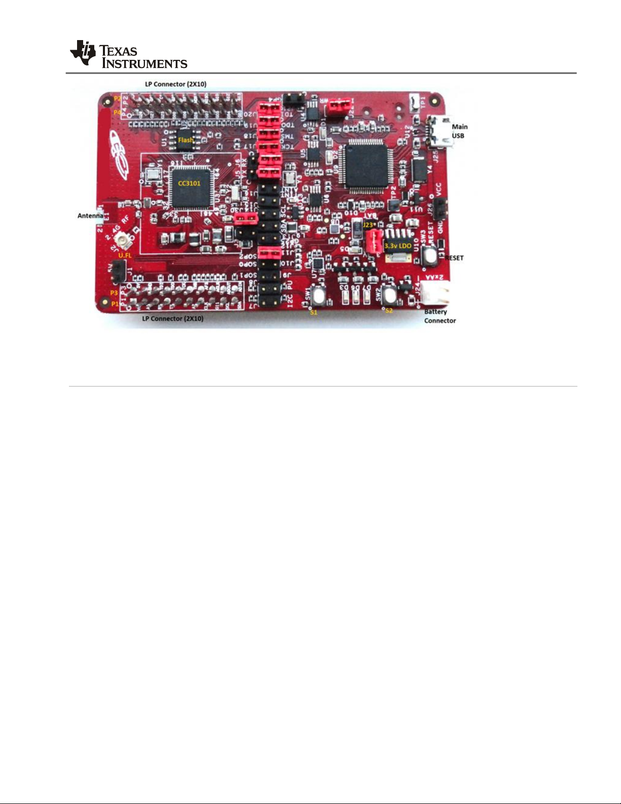
Board overview
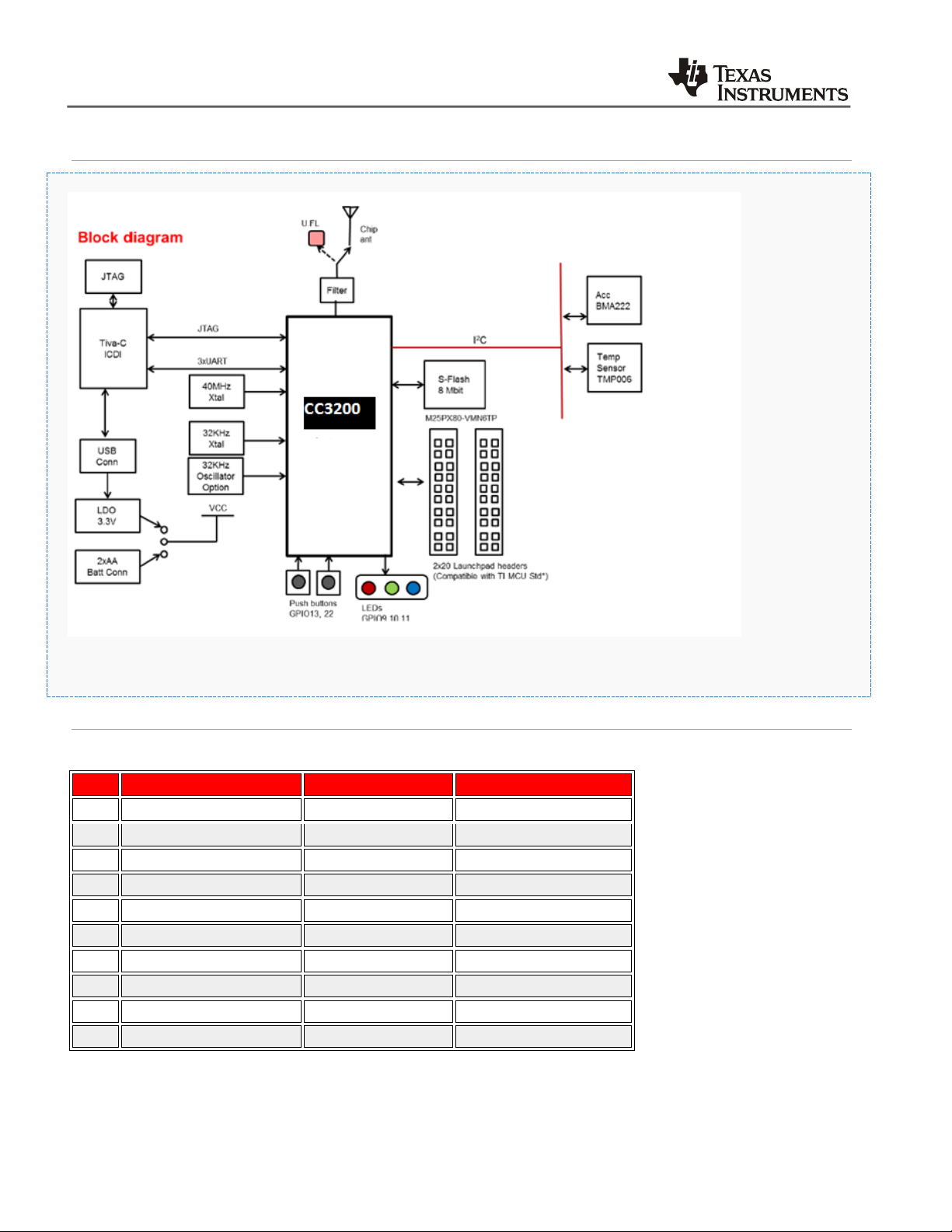
This board is designed to be used as a standalone development platform for application development using the CC3200
device. It can be also used in conjunction with compatible booster-packs to enhance the peripherals available in the
system. The board features on-board emulation using FTDI device and has an array of sensors for an out of the box
experience. This board can be directly connected to the PC using software development platforms including CCS and IAR.
2
CC3200-LAUNCHXL User’s Guide
Page 3
CC3200-LAUNCHXL User’s Guide
Features
CC3200 WIFI application processor
USB interface to PC for CCS/IAR using XDS ICDI USB drivers
Flash update over the USB using Simple Link Programmer.
2x20 pin Connectors : Compatible to TI MCU Launch Pads with added functions.
Standalone development platform featuring sensors, LEDs and push-buttons
Power from USB for the launchpad as well as external boosterpack
Operates from 2xAA alkaline battery.
Push buttons for RESET
3 user LEDs
On-board antenna and U.FL connector selectable using a capacitor re-work.
Sensors including temperature, 3-axis accelerometer.
CC3200-LAUNCHXL User’s Guide
3
Page 4
CC3200-LAUNCHXL User’s Guide
Pin No
Signal name
Direction w.r.t CC3200
Comments
P1.1
VCC(3.3V)
OUT
Max 100mA for peripherals
P1.2
GPIO03/ADC_CH2
IN P1.3
GPIO_02/UART1_RX
IN P1.4
GPIO_01/UART1_TX
OUT
P1.5
OUT
UNUSED
P1.6
GPIO_04/ADC_CH3
IN
P1.7
GPIO_14/SPI_CLK
OUT
P1.8
GPIO_11
P1.9
GPIO_10/GPIO_12/I2C_SCL
BD
2.2K pull-ups on board
P1.10
GPIO_11/GPIO_13/I2C_SDA
BD
2.2K pull-ups on board
Hardware description
Connector description
1.1.1.1 P1 connector assignment
4
CC3200-LAUNCHXL User’s Guide
Page 5
Pin No
Signal name
Direction w.r.t CC3200
Comments
P2.1
GND
PWR
P2.2
GPIO_22
OUT
P2.3
GPIO_17/SPI_CS
OUT
P2.4
GPIO_28
OUT
P2.5
RESET
OUT
Reset output from board
P2.6
GPIO_16/SPI_DOUT
OUT
P2.7
GPIO_15/SPI_DIN
IN
P2.8
GPIO_10
BD P2.9
GPIO_12
BD P2.10
GPIO_13
BD
Pin No
Signal name
Direction w.r.t CC3200
Comments
P3.1
5V
P3.2
GND
P3.3
GPIO_23/TDI
IN
P3.4
GPIO_24/TDO
OUT
P3.5
GPIO_28/TCK
IN
P3.6
GPIO_29/TMS
IN
P3.7
GPIO_08/AUD_SYNC
OUT
P3.8
GPIO_30/AUD_CLK
OUT
P3.9
GPIO_09/AUD_DOUT
OUT
P3.10
GPIO_00/AUD_DIN
IN
Pin No
Signal name
Direction w.r.t CC3200
Comments
P4.1
GPIO_26
OUT
P4.2
GPIO_27
OUT
P4.3
GPIO_25
OUT
P4.4
GPIO_00/GPIO_07/UART1_RTS
OUT
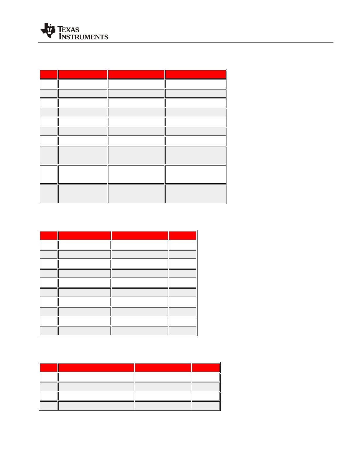
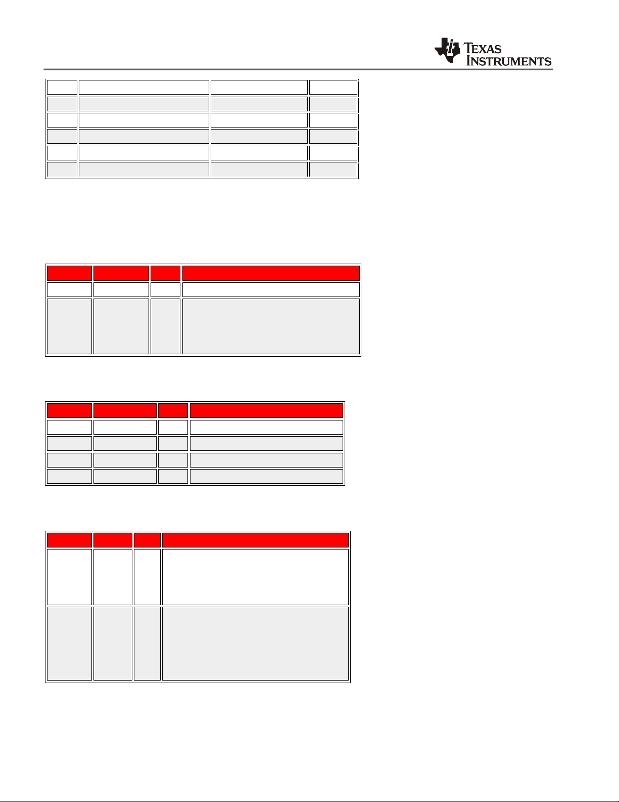
1.1.1.2 P2 connector assignment
CC3200-LAUNCHXL User’s Guide
1.1.1.3 P3 connector assignment
1.1.1.4 P4 connector assignment
CC3200-LAUNCHXL User’s Guide
5
Page 6
CC3200-LAUNCHXL User’s Guide
P4.5
GPIO_06/UART1_CTS
IN
P4.6
GPIO_28
I/O P4.7
GPIO_07/NWP_LOGGER
OUT
P4.8
GPIO_05/WLAN_LOGGER
OUT
P4.9
GPIO_04/WL_RS232_RX
IN P4.10
GPIO_03/WL_RS232_TX
OUT
Reference
Function
Value
Comments
J22
ICDI Power
Closed
Supplies 3.3V to the ICDI
J23
Board power
2-3
1-2
Supplies 3.3V to the board from USB
Supplies power to the board from battery
Reference
Function
Value
Comments
J7
Pull-up on SDA
Closed
Enable 3.3K pull-ups on the SDA
J8
Pull-up on SCL
Closed
Enable 3.3K pull-ups on the SDA
J13
SDA
Closed
Connect on-board sensors to I2C bus
J14
SCL
Closed
Connect on-board sensors to I2C bus
Reference
Function
Value
Comments
J5
UART TX
1-2
2-3
Routes UART to 2x20 pin for Booster pack
Routes UART to ICDI for flash programming.
J6
UART RX
1-2
2-3
Routes UART to 2x20 pin for Booster pack
Routes UART to ICDI for flash programming
1.1.1.5 Jumper settings
1.1.1.5.1 Power
1.1.1.5.2 I2C
1.1.1.5.3 UART
6
CC3200-LAUNCHXL User’s Guide
Page 7
Mode
SOP2
J11
SOP1
J9
SOP0
J10
Functional mode with 4 Wire JTAG
0 0 0
Functional Mode with 2 Wire SWD
0 0 1
Flash programming mode over UART
1 0 0
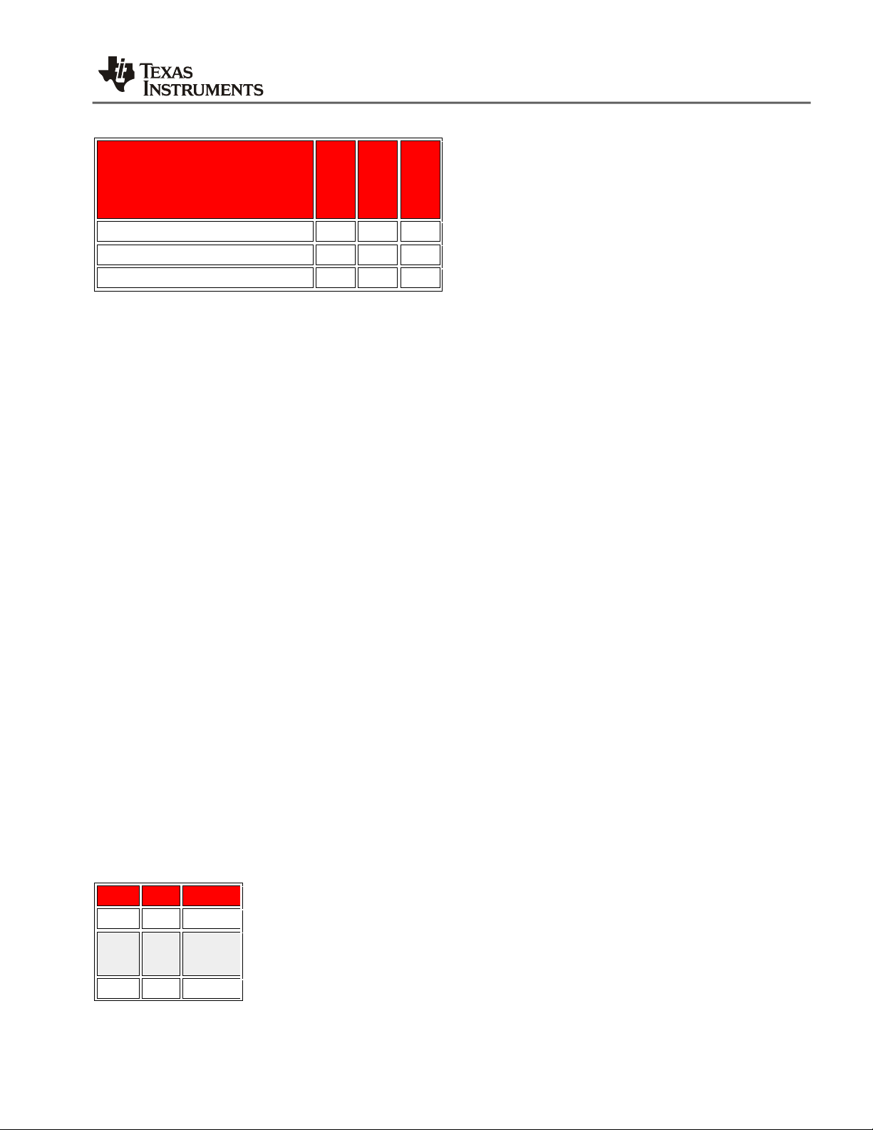
Pin No
Signal
Direction
J17
TCK
In
J18
TMS
In
J19
TDO
Out
1.1.1.5.4 Operating modes (Debug)
Note : '0' indicates jumper is open
CC3200-LAUNCHXL User’s Guide
1.1.2 Power selection
The board can be powered from the USB connector using the on-board LDO (3.3V) or using an external battery (2xAA). The
battery is connected to J24. There is built-in reverse polarity protection for the battery connector.
The selection between the battery and USB power is performed using the jumper J23.
J23(1-2) [Battery powered]
J23(2-3) [USB powered]
1.1.3 USB connections
The Launchpad features an USB connector labelled J25.
J25 is used to power the board and also for the JTAG emulation and UART ports. Currently only one UART port for the
flash programming is provided on the board. The board requires the installation of Stellaris ICDI Drivers to be installed for
proper operation. This is provided as part of the SDK release.
1.1.4 JTAGsignals
The JTAG lines are brought out on separate headers on the PCB. The jumpers are shorted to connect the CC3200 JTAG to
the ICDI device on-board. To use an external emulator, these jumpers have to be un-installed and the JTAG signals to be
connected on the jumpers below.
JTAG connector
CC3200-LAUNCHXL User’s Guide
7
Page 8

CC3200-LAUNCHXL User’s Guide
J20
TDI
In
Reference
Colour
GPIO maping
comment
D7
GREEN
GPIO_11
Glows when GPIO = 1.
D6
YELLOW
GPIO_10
Glows when GPIO = 1.
D3
RED
GPIO_09
Glows when GPIO = 1
SW1
NA
GPIO_13
High when pressed.
SW2
NA
GPIO_22
High when pressed.
Reference
Part No
Type
Address
U8
TMP006
Temperature sensor
0x41
U7
BMA222
3-Axis Accelerometer
0X18
Schematics
Schematics
Assembly diagram
Placement diagram
Bill of materials
Bill of materials
ECO List (Changes made to the sch/bom )
Gerber Files
pcb (Gerber) files
1.1.5 User LEDs and push-buttons
There are 3 user LEDs on the board along with 2 push buttons. The usage can be controlled by the application program.
Signal mapping
1.1.6 On-board sensors
There are two sensors on the board which are connected to the I2C bus. The sensors can be isolated from the I2C bus
using the jumpers J14 and J13. By default the pull-ups on the I2C are not enabled. To enable these install jumpers J7 and
J8.
The sensors available on the board are listed below with their address
Hardware documents
LP V2.0 RevA- PG 1.11
Software Information
1.1.7 USB driver (For BP/LP)
For Windows (XP, Win7) Link
8
CC3200-LAUNCHXL User’s Guide
Page 9
CC3200-LAUNCHXL User’s Guide
CC3200-LAUNCHXL User’s Guide
9
Page 10

CC3200-LAUNCHXL User’s Guide
10
CC3200-LAUNCHXL User’s Guide
Page 11

CC3200-LAUNCHXL User’s Guide
CC3200-LAUNCHXL User’s Guide
11
Page 12

CC3200-LAUNCHXL User’s Guide
12
CC3200-LAUNCHXL User’s Guide
Page 13

CC3200-LAUNCHXL User’s Guide
CC3200-LAUNCHXL User’s Guide
13
 Loading...