

Page 1

1 General Description
The LM3549 is a high power LED driver with up to 700mA output current. It has three constant current
LED drivers and a buck boost SMPS for driving RGB LEDs with high efficiency. LED drivers are designed
for sequential drive so only one driver can be enabled at a time.
LED driver output current settings can be stored to integrated non-volatile memory which allows standalone operation without I2C interface. Non-volatile memory is re-writable so current setting can be changed
if needed.
LM3549 has a fault detection feature that can detect several different fault conditions. In case of a fault
error flags are set and FAULT output sends interrupt to control logic. Error flags can be read through I2C
interface.
Total brightness can be controlled with PWM input or with master fader register if I2C interface is used.
LM3549 evaluation board is designed to help getting familiarized with the LM3549. It can be used to
measure key parameters of the LM3549 and to speed up design in of the device. The evaluation board
has a microcontroller that acts as an USB to I2C interface. Microcontroller is also used to manipulate the
digital control signals of the LM3549. LM3549 evaluation board can be powered from the USB interface or
from external power supply. If evaluation board is used to measure the electrical parameters of the
LM3549 or used with high output currents external power supply needs to be used. If evaluation board is
used to check the functionality of the LM3549 with small output currents or to support software
development it can be powered directly from USB interface. This document describes how to get the
LM3549 evaluation board up and running and how to use evaluation software.
User's Guide
SNVA443A–August 2010–Revised April 2013
AN-2062 LM3549 Evaluation Kit
2 What Is Needed
To get started you will need:
• LM3549 evaluation board
• LM3549 evaluation software (LM3549.exe)
• USB cable
• PC with one free USB port
All trademarks are the property of their respective owners.
SNVA443A–August 2010–Revised April 2013 AN-2062 LM3549 Evaluation Kit
Submit Documentation Feedback
Copyright © 2010–2013, Texas Instruments Incorporated
1
Page 2
What Is Needed
www.ti.com
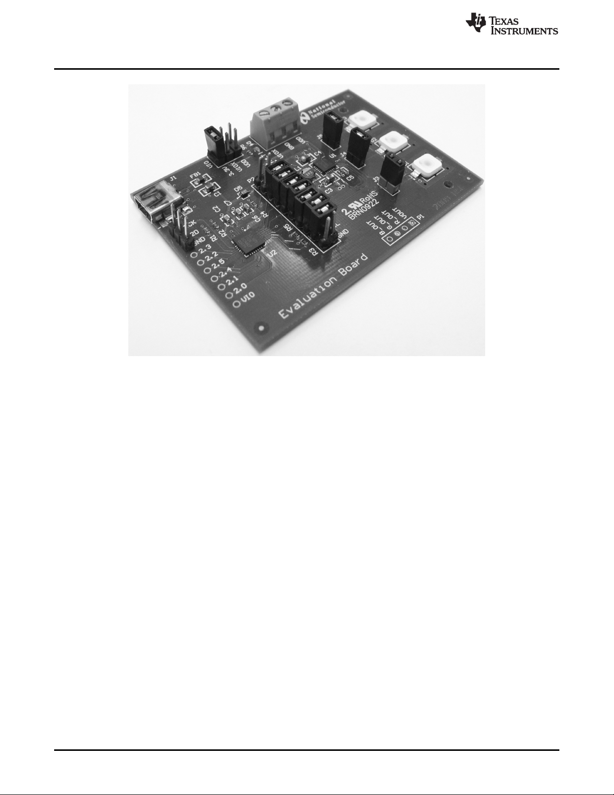
Figure 1. Evaluation Board
2
AN-2062 LM3549 Evaluation Kit SNVA443A–August 2010–Revised April 2013
Copyright © 2010–2013, Texas Instruments Incorporated
Submit Documentation Feedback
Page 3
www.ti.com
3 Hardware Set-Up
Hardware Set-Up
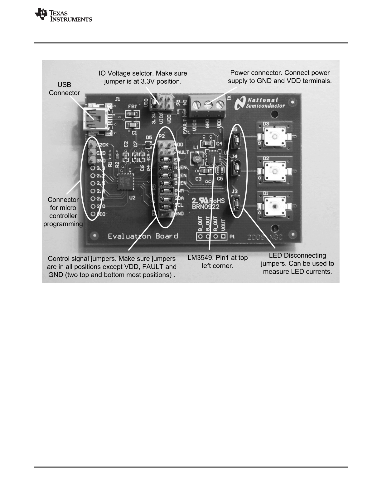
Figure 2. LM3549 Evaluation Board Setup
The LM3549 evaluation kit is based on a one board system, where the USB communication and
evaluation related components are assembled onto one board, (see Figure 2). The evaluation board was
designed especially for evaluation and, therefore, is not optimized for the smallest layout size. The
components are physically large to make changing component values easier.
LM3549 input voltage VDD can be supplied from the USB port or by connecting an external power supply
to the X1 connector. If voltage is supplied from USB port shunt needs to be placed on the VDD position of
P2 pin rail. If external power supply is used this shunt needs to be removed. USB port's maximum output
current is 500mA. This is not enough to drive the LEDs with maximum output current but can be used to
test functionality of the LM3549.
Figure 2 shows how to setup the LM3549 evaluation board. This configuration uses onboard
microcontroller to control the LM3549’s logic inputs. If one wishes to use external source to drive the
control signals, control signal jumpers needs to be removed and external control signals needs to be
connected to the right side of the P2 pin rail. Control signals are labeled for easy connection.
I2C interface pull-up resistors are placed on the microcontroller side of the control signal jumpers. If
external I2C interface is connected to the board it needs to have pull-up resistors. LM3549 I2C ID is 36h
(in 7bit format) -> write = 6Ch (8-bit format) and read = 6Dh (8-bit format)
SNVA443A–August 2010–Revised April 2013 AN-2062 LM3549 Evaluation Kit
Submit Documentation Feedback
Copyright © 2010–2013, Texas Instruments Incorporated
3
Page 4

Connecting the Evaluation Board to a Computer
The onboard microcontroller has USB interface to communicate with PC. Connect evaluation board to PC
with USB cable. Evaluation software is used to control LM3549’s logic inputs and to use the I2C interface.
Evaluation software setup and use are described in the following sections
LM3549 evaluation board has three high current LEDs. These LED's are very bright even with minimum
current setting. Never look straight into the LEDs. This can damage your eyes! It is good practice to
always cover the LEDs with something to avoid looking straight into them.
3.1 Connector Listing
• J1 - USB connector. Use this to connect the LM3549 to your PC.
• VIO - selector for digital logic levels. There should be a shunt in 3.3V position.
• X1- power supply connector. VDD terminal can be used to supply LM3549 input voltage from external
power supply. VIOX terminal can be used to connect external voltage for the digital signals.
• Connector for microcontroller programming is used to program the on-board microcontroller. This has
no user functions and needs to always be unconnected.
• P2 - P2 pin rail is used to connect on-board microcontroller to LM3549 digital lines. If you want to
connect LM3549 to your own system, shunts can be removed and your system can be connected to
the right side pins of the P2 pin rail.
• J3, J4 and J5 - LED disconnecting jumpers. These can be used to disconnect the LEDs from LM3549
LED outputs. This can be used to test the fault detection or to measure LED currents.
• P1 - Connector for VOUT and LED outputs. This can be used to connect external LEDs to the LM3549
evaluation board.
www.ti.com
4 Connecting the Evaluation Board to a Computer
1. Check that the jumpers on the evaluation board are on wanted positions.
2. Connect external power supply to the evaluation board or, if evaluation board is to be powered form
USB port, set shunt to VDD position of the P2 pin rail.
3. Connect the USB board to your computer using a USB cable
4. Start the evaluation software LM3549.exe
5. Evaluation software may prompt you to update firmware of the LM3549 evaluation board. If it does
click ok and wait until update is completed.
6. Status bar at the center of the bottom row should say "OK" on green background. This indicates that
I2C interface between microcontroller and LM3549 is working correctly.
7. The evaluation kit is now fully up and running and the device can be controlled through the PC
software. Figure 3 shows the evaluation software user interface (Control Panel).
4
AN-2062 LM3549 Evaluation Kit SNVA443A–August 2010–Revised April 2013
Copyright © 2010–2013, Texas Instruments Incorporated
Submit Documentation Feedback
Page 5
www.ti.com
Controlling the Evaluation Board
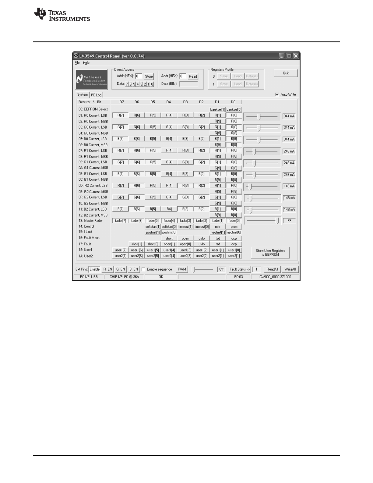
Figure 3. LM3549 Evaluation Software Control Panel
You should see USB OK message on the status bar (shown in the lower part of the window). If the USB
communication is not working correctly, shut down the evaluation software and unplug the USB cable.
Plug in the USB cable again and wait about 5 seconds and restart the evaluation software. You can also
try toggling the Enable button few times.
5 Controlling the Evaluation Board
Evaluation software doesn’t need installation and can be run by double clicking the icon. If evaluation
board is set up correctly, the evaluation software’s user interface should look like in Figure 3. When
software starts up, it sets the Enable control to “1” and reads the control register values. The Status bar at
the center of the bottom row should say OK on green background. This indicates that I2C interface
between microcontroller and LM3549 is working correctly. If there are any error messages on red
background something is wrong with the I2C interface. In this case, check the control signal jumpers and
verify that proper VDD voltage is applied to the board.
The evaluation software provides read-write control over the registers within the LM3549. Bits can be set
from a logical '1' to a logical '0' or vice versa by a mouse click and for some settings there is a slider
control.
SNVA443A–August 2010–Revised April 2013 AN-2062 LM3549 Evaluation Kit
Submit Documentation Feedback
Copyright © 2010–2013, Texas Instruments Incorporated
5
Page 6

Controlling the Evaluation Board
www.ti.com
Figure 4 shows the I2C Log tab of the evaluation software. All I2C write commands will be logged and can
be seen on I2C Log tab. You can copy/paste write commands into his/her own application if needed.
5.1 I2C Communication
LM3549 registers 00h-16h and 19h – 1Ah are read/write accessible using controls (buttons and track bars
where available) on System tab of the software window. Register 17h (Fault register) is read only register.
Button ReadAll reads all register values of the LM3549 and updates register map related buttons and
track bars according to results. Note that ReadAll button doesn't update external pin buttons. Button
WriteAll stores values of buttons and track bars to LM3549. Note that specific register will be updated
immediately when clicking/dragging on its control buttons or track bar if Auto Write checkbox is checked.
I2C communication status after register read or write command are shown on status bar (at bottom of
window).
6
AN-2062 LM3549 Evaluation Kit SNVA443A–August 2010–Revised April 2013
Figure 4. I2C Log View
Copyright © 2010–2013, Texas Instruments Incorporated
Submit Documentation Feedback
Page 7

www.ti.com
5.2 Direct Access to Registers
Controls on the frame Direct Access allows you to read/write from/to the chip registers manually. Enter the
register address to the Addr field and choose the binary value by clicking on the Data bits 7...0 and write
the selected value to the chip register by clicking on the Store button. Note that after clicking the Store
button all the register values will be read back automatically. Disable the automatic read by unchecking
Auto Write checkbox. Enter the register address to the Addr field and click the Read button to read the
specific register. The result will be displayed in the Data field in binary format.
5.3 Control Signals
Buttons Enable, R_EN, G_EN, B_EN and PWM are used to manipulate input pins of the LM3549. Button
Fault Status is used to read status of FAULT pin. Pin value appears to value bar beside the button.
Setting Enable button high puts LM3549 to standby mode. I2C registers can be read and written in
standby mode but buck-boost converter and LED drivers are off. Setting Enable button low sets LM3549
to shutdown mode.
When device is on the standby mode LEDs can be turned on one at the time by clicking R_EN, G_EN or
B_EN. Even if two or more buttons are turned high at the same time, only the LED that was set high first
will be on.
Generation of special sequence of R, G and B signals can be enabled/disabled by checking/unchecking
Enable sequence checkbox. Period of the sequence is about 60 Hz and is similar to that described in the
LM3549 High Power Sequential LED Driver Data Sheet (SNVS640). Note that clicking on one of the
R_EN, G_EN, B_EN button will disable sequence generation automatically.
PWM generation can be enabled by dragging PWM track bar on bottom of the window. PWM frequency is
about 7.6kHz.
Controlling the Evaluation Board
5.4 EEPROM Programming
Desired default register values can be stored to EEPROM. These values are always read back to registers
when Enable button is set from low to high. Keep the Enable button on and set all x_EN buttons off and
uncheck Enable sequence box. Write suitable values to all user registers. Set VDD to 5.0V and click on
the Store User Registers to EEPROM button. Set the Enable button off and back to on. Read all registers
by pressing the ReadAll button and verify that the values match with the stored values.
5.5 Fault LED
LED D4 is connected to LM3549's open drain fault output. If LM3549 detects any fault conditions e.g. LED
short or LED open it pulls the fault output low and turns on the fault LED. LM3549 has a fault register
which indicates what fault has occurred. Reading the fault register reset it's state and also reset the fault
output to high-z state. Different fault conditions are described in the LM3549 High Power Sequential LED
Driver Data Sheet (SNVS640).
SNVA443A–August 2010–Revised April 2013 AN-2062 LM3549 Evaluation Kit
Submit Documentation Feedback
Copyright © 2010–2013, Texas Instruments Incorporated
7
Page 8

Schematic
6 Schematic
www.ti.com
Figure 5. Schematic of the LM3549 Evaluation Board
8
AN-2062 LM3549 Evaluation Kit SNVA443A–August 2010–Revised April 2013
Copyright © 2010–2013, Texas Instruments Incorporated
Submit Documentation Feedback
Page 9

www.ti.com
Bill of Materials (BOM)
7 Bill of Materials (BOM)
Designator Value Footprint Comment Description Quantity
C1, C4 10 μF 0805 Capacitor 2
C2, C7 100 nF 0805 Capacitor 2
C3 4.7 μF 0805 Capacitor 1
C5 22 μF 1210 Capacitor 1
C6 4.7 μF 0603 Capacitor 1
D1 LR W5AP Red LED Dragon LED 1
D2 LT W5AP Green LED Dragon LED 1
D3 LD W5AP Blue LED Dragon LED 1
D4 LS L296 0603 LED Red LED Fault indicator LED 1
D5 BAT760 Schotky diode 1
FB1 BK2125HS101-T 2125 Ferrite bead 1
L1 2.2 μH VLF4014ST-2r2M1R9 TDK SMD inductor 1
R1 10 kΩ 0603 Resistor 1
R2, R3, R4, R5 1.5 kΩ 0603 Resistor 4
R6 330Ω 0603 Resistor 1
R7 0Ω 0805 Resistor 1
U1 LM3549 WQFN24 1
U2 C8051F326 QFN-28 Microcontroller 1
Osram Diamond
Osram Diamond
Osram Diamond
SNVA443A–August 2010–Revised April 2013 AN-2062 LM3549 Evaluation Kit
Submit Documentation Feedback
Copyright © 2010–2013, Texas Instruments Incorporated
9
Page 10

IMPORTANT NOTICE
Texas Instruments Incorporated and its subsidiaries (TI) reserve the right to make corrections, enhancements, improvements and other
changes to its semiconductor products and services per JESD46, latest issue, and to discontinue any product or service per JESD48, latest
issue. Buyers should obtain the latest relevant information before placing orders and should verify that such information is current and
complete. All semiconductor products (also referred to herein as “components”) are sold subject to TI’s terms and conditions of sale
supplied at the time of order acknowledgment.
TI warrants performance of its components to the specifications applicable at the time of sale, in accordance with the warranty in TI’s terms
and conditions of sale of semiconductor products. Testing and other quality control techniques are used to the extent TI deems necessary
to support this warranty. Except where mandated by applicable law, testing of all parameters of each component is not necessarily
performed.
TI assumes no liability for applications assistance or the design of Buyers’ products. Buyers are responsible for their products and
applications using TI components. To minimize the risks associated with Buyers’ products and applications, Buyers should provide
adequate design and operating safeguards.
TI does not warrant or represent that any license, either express or implied, is granted under any patent right, copyright, mask work right, or
other intellectual property right relating to any combination, machine, or process in which TI components or services are used. Information
published by TI regarding third-party products or services does not constitute a license to use such products or services or a warranty or
endorsement thereof. Use of such information may require a license from a third party under the patents or other intellectual property of the
third party, or a license from TI under the patents or other intellectual property of TI.
Reproduction of significant portions of TI information in TI data books or data sheets is permissible only if reproduction is without alteration
and is accompanied by all associated warranties, conditions, limitations, and notices. TI is not responsible or liable for such altered
documentation. Information of third parties may be subject to additional restrictions.
Resale of TI components or services with statements different from or beyond the parameters stated by TI for that component or service
voids all express and any implied warranties for the associated TI component or service and is an unfair and deceptive business practice.
TI is not responsible or liable for any such statements.
Buyer acknowledges and agrees that it is solely responsible for compliance with all legal, regulatory and safety-related requirements
concerning its products, and any use of TI components in its applications, notwithstanding any applications-related information or support
that may be provided by TI. Buyer represents and agrees that it has all the necessary expertise to create and implement safeguards which
anticipate dangerous consequences of failures, monitor failures and their consequences, lessen the likelihood of failures that might cause
harm and take appropriate remedial actions. Buyer will fully indemnify TI and its representatives against any damages arising out of the use
of any TI components in safety-critical applications.
In some cases, TI components may be promoted specifically to facilitate safety-related applications. With such components, TI’s goal is to
help enable customers to design and create their own end-product solutions that meet applicable functional safety standards and
requirements. Nonetheless, such components are subject to these terms.
No TI components are authorized for use in FDA Class III (or similar life-critical medical equipment) unless authorized officers of the parties
have executed a special agreement specifically governing such use.
Only those TI components which TI has specifically designated as military grade or “enhanced plastic” are designed and intended for use in
military/aerospace applications or environments. Buyer acknowledges and agrees that any military or aerospace use of TI components
which have not been so designated is solely at the Buyer's risk, and that Buyer is solely responsible for compliance with all legal and
regulatory requirements in connection with such use.
TI has specifically designated certain components as meeting ISO/TS16949 requirements, mainly for automotive use. In any case of use of
non-designated products, TI will not be responsible for any failure to meet ISO/TS16949.
Products Applications
Audio www.ti.com/audio Automotive and Transportation www.ti.com/automotive
Amplifiers amplifier.ti.com Communications and Telecom www.ti.com/communications
Data Converters dataconverter.ti.com Computers and Peripherals www.ti.com/computers
DLP® Products www.dlp.com Consumer Electronics www.ti.com/consumer-apps
DSP dsp.ti.com Energy and Lighting www.ti.com/energy
Clocks and Timers www.ti.com/clocks Industrial www.ti.com/industrial
Interface interface.ti.com Medical www.ti.com/medical
Logic logic.ti.com Security www.ti.com/security
Power Mgmt power.ti.com Space, Avionics and Defense www.ti.com/space-avionics-defense
Microcontrollers microcontroller.ti.com Video and Imaging www.ti.com/video
RFID www.ti-rfid.com
OMAP Applications Processors www.ti.com/omap TI E2E Community e2e.ti.com
Wireless Connectivity www.ti.com/wirelessconnectivity
Mailing Address: Texas Instruments, Post Office Box 655303, Dallas, Texas 75265
Copyright © 2013, Texas Instruments Incorporated
 Loading...