

Page 1
User's Guide
SNVA327B–March 2008–Revised May 2013
AN-1793 LM3433 4A to 20A LED Driver Evaluation Board
1 Introduction
The LM3433 is an adaptive constant on-time DC/DC buck constant current controller designed to drive a
high brightness LEDs (HB LED) at high forward currents. It is a true current source that provides a
constant current with constant ripple current regardless of the LED forward voltage drop. The board can
accept an input voltage ranging from -9V to -14V w.r.t. GND. The output configuration allows the anodes
of multiple LEDs to be tied directly to the ground referenced chassis for maximum heat sink efficacy when
a negative input voltage is used.
2 LM3433 Board Description
The evaluation board is designed to provide a constant current in the range of 4A to 20A. The LM3433
requires two input voltages for operation. A positive voltage with respect to GND is required for the bias
and control circuitry and a negative voltage with respect to GND is required for the main power input. This
allows for the capability of using common anode LEDs so that the anodes can be tied to the ground
referenced chassis. The evaluation board only requires one input voltage of -12V with respect to GND.
The positive voltage is supplied by the LM5002 circuit. The LM5002 circuit also provides a UVLO function
to remove the possibility of the LM3433 from drawing high currents at low input voltages during startup.
Initially the output current is set at the minimum of approximately 4A with the POT P1 fully counterclockwise. To set the desired current level a short may be connected between LED+ and LED-, then use a
current probe and turn the POT clockwise until the desired current is reached. PWM dimming FETs are
included on-board for testing when the LED can be connected directly next to the board. A shutdown test
post on J2, ENA, is included so that startup and shutdown functions can be tested using an external
voltage.
3 Setting the LED Current
The LM3433 evaluation board is designed so that the LED current can be set in multiple ways. There is a
shunt on J2 initially connecting the ADJ pin to the POT allowing the current to be adjusted using the POT
P1. This POT will apply a voltage to the ADJ pin between 0.3V and 1.5V w.r.t. GND to adjust the voltage
across the sense resistor (R
) R15. The shunt may also be removed and an external voltage positive
SENSE
w.r.t. GND can then be applied to the ADJ test point on the board. A 5mΩ resistor comes mounted on the
board so using the V
I
= V
LED
SENSE/RSENSE
SENSE
vs. V
graph in the Section 6 section the current can be set using Equation 1:
ADJ
Alternatively the shunt can be removed and connect the ADJ test point can be connected to the VINX test
point to fix V
SENSE
at 60mV.
4 PWM Dimming
The LM3433 is capable if high speed PWM dimming in excess of 40kHz. Dimming is accomplished by
shorting across the LED with a FET(s). Dimming FETs are included on the evaluation board for testing
LEDs placed close to the board. The FETs on the evaluation board should be removed if using dimming
FETs remotely placed close to the LED (recommended).
All trademarks are the property of their respective owners.
SNVA327B–March 2008–Revised May 2013 AN-1793 LM3433 4A to 20A LED Driver Evaluation Board
Submit Documentation Feedback
Copyright © 2008–2013, Texas Instruments Incorporated
(1)
1
Page 2

Life
ACTUAL
= Life
RATED
X 2
T
CORE
- T
ACTUAL
7
( )
I
RMS
=
V
LED
(|VEE|-V
LED
)
|VEE|
I
LED
High Current Operation and Component Lifetime
To use the dimming function apply square wave to the PWM test point on the board that has a positive
voltage w.r.t. GND. When this pin is pulled high the dimming FET is enabled and the LED turns off. When
it is pulled low the dimming FET is turned off and the LED turns on. A scope plot of PWM dimming is
included in the Typical Performance Characteristics section showing 30kHz dimming at 50% duty cycle.
5 High Current Operation and Component Lifetime
When driving high current LEDs, particularly when PWM dimming, component lifetime may become a
factor. In these cases the input ripple current that the input capacitors are required to withstand can
become large. At lower currents long life ceramic capacitors may be able to handle this ripple current
without a problem. At higher currents more input capacitance may be required. To remain cost effective
this may require putting one or more aluminum electrolytic capacitors in parallel with the ceramic input
capacitors. Since the operational lifetime of LEDs is very long (up to 50,000 hours) the longevity of an
aluminum electrolytic capacitor can become the main factor in the overall system lifetime. The first
consideration for selecting the input capacitors is the RMS ripple current they will be required to handle.
This current is given by Equation 2:
The parallel combination of the ceramic and aluminum electrolytic input capacitors must be able to handle
this ripple current. The aluminum electrolytic in particular should be able to handle the ripple current
without a significant rise in core temperature. A good rule of thumb is that if the case temperature of the
capacitor is 5°C above the ambient board temperature then the capacitor is not capable of sustaining the
ripple current for its full rated lifetime and a more robust or lower ESR capacitor should be selected.
The other main considerations for aluminum electrolytic capacitor lifetime are the rated lifetime and the
ambient operating temperature. An aluminum electrolytic capacitor comes with a lifetime rating at a given
core temperature, such as 5000 hours at 105°C. As dictated by physics the capacitor lifetime should
double for each 7°C below this temperature the capacitor operates at and should halve for each 7°C
above this temperature the capacitor operates at. A good quality aluminum electrolytic capacitor will also
have a core temperature of approximately 3°C to 5°C above the ambient temperature at rated RMS
operating current. So as an example, a capacitor rated for 5,000 hours at 105°C that is operating in an
ambient environment of 85°C will have a core temperature of approximately 90°C at full rated RMS
operating current. In this case the expected operating lifetime of the capacitor will be approximately just
over 20,000 hours. The actual lifetime (Life
) can be found using Equation 3:
ACTUAL
www.ti.com
(2)
2
Where Life
is the rated lifetime at the rated core temperature T
RATED
. For example, if the ambient
CORE
temperature is 85°C the core temperature is 85°C + 5°C = 90°C. (105°C - 90°C)/7°C = 2.143. 2^2.413 =
4.417. So the expected lifetime is 5,000*4.417 = 22,085 hours. Long life capacitors are recommended for
LED applications and are available with ratings of up to 20,000 hours or more at 105°C.
AN-1793 LM3433 4A to 20A LED Driver Evaluation Board SNVA327B–March 2008–Revised May 2013
Copyright © 2008–2013, Texas Instruments Incorporated
Submit Documentation Feedback
(3)
Page 3
www.ti.com
High Current Operation and Component Lifetime
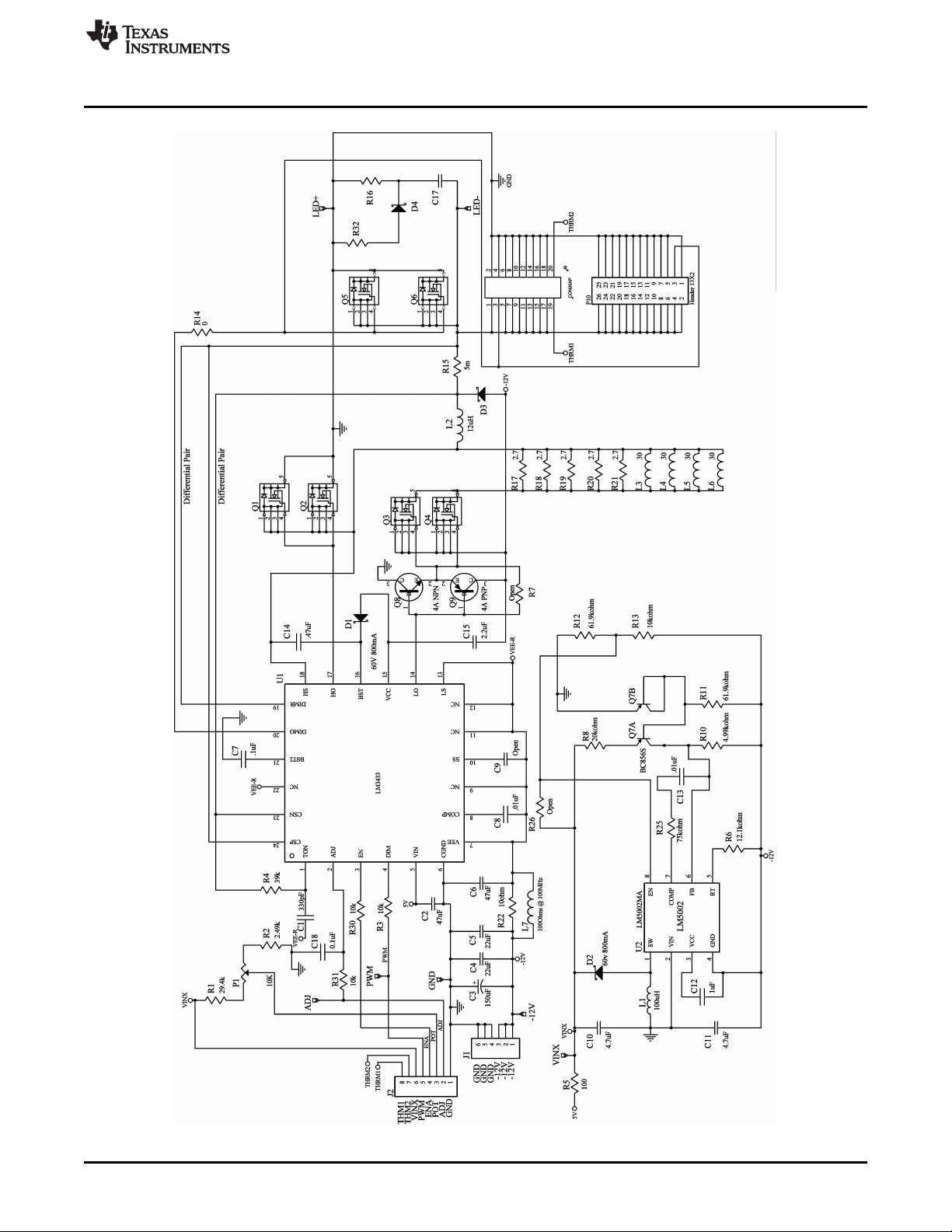
Figure 1. LM3433 Evaluation Board Schematic
SNVA327B–March 2008–Revised May 2013 AN-1793 LM3433 4A to 20A LED Driver Evaluation Board
Submit Documentation Feedback
Copyright © 2008–2013, Texas Instruments Incorporated
3
Page 4
High Current Operation and Component Lifetime
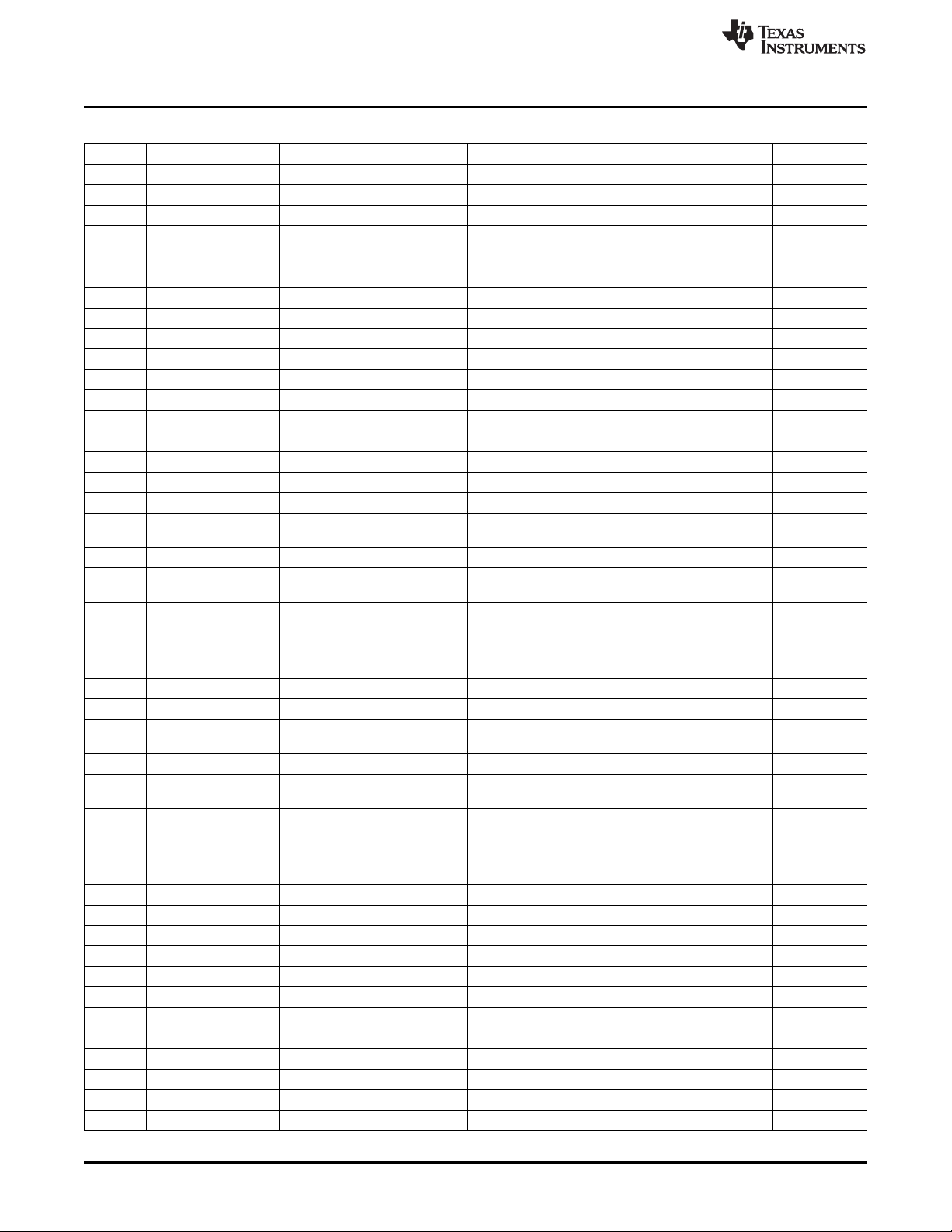
Table 1. Bill of Materials (BOM)
Qty ID Part Number Type Size Parameters Vendor
1 U1 LM3433 LED Driver WQFN-24 TI
1 U2 LM5002 Boost Regulator SOIC-8 TI
1 C1 C0805C331J5GACTU Capacitor 0805 330pF, 50V Kemet
1 C2 GRM31CR60J476KE19L Capacitor 1206 47µF, 6.3V Murata
1 C3 16SA150M Capacitor MULTICAP 150µF, 16V Sanyo
2 C4, C5 GRM32ER61C226KE20L Capacitor 1210 22µF, 16V Murata
1 C6 GRM32ER61C476ME15L Capacitor 1210 47µF, 16V Murata
1 C7 C0805C104J5RACTU Capacitor 0805 0.1µF, 50V Kemet
2 C8, C13 HMK212BJ103KG-T Capacitor 0805 10nF, 100V Taiyo Yuden
C9 OPEN 0805
2 C10, C11 GRM21BR61C475KA Capacitor 0805 4.7µF, 16V Murata
1 C12 0805YD105KAT2A Capacitor 0805 1µF, 16V AVX
1 C14 B37941K9474K60 Capacitor 0805 0.47µF, 16V EPCOS Inc .
1 C15 GRM21BF51E225ZA01L Capacitor 0805 2.2µF, 25V Murata
C17 OPEN 0805
1 C18 08055C104JAT2A Capacitor 0805 0.1µF, 50V AVX
2 D1, D2 MA2YD2600L Diode SOD-123 60V, 800mA Panasonic
1 D3 MBRS240LT3 Diode SMB 40V, 2A ON
Semiconductor
D4 OPEN SMB
1 J2 B8B-EH-A(LF)(SN) Connector JST Sales
America, Inc.
1 J1 1761582001 Connector Weidmuller
1 J9 TFML-110-02-S-D Connector TFM-110-02- Samtec
X-D-LC
1 L1 LPS3008-104ML Inductor 3008 100µH, 150mA Coilcraft
1 L2 GA3252-AL Inductor GA3252-AL 12µH, 14A Coilcraft
4 L3, L4, L5, L6 MPZ2012S300A Ferrite Bead 0805 30Ω @ 100MHz TDK
1 L7 MPZ2012S101A Ferrite Bead 0805 100Ω @ TDK
100MHz
1 P1 3352T-1-103LF Potentiometer BOURNS2 10kΩ Bourns
1 P10 3429-6002 Connector HDR13x2 13X2 Pin 3M
Header
2 Q1, Q2, Q3, Q4, Q5, NTMFS4841NH FET PowerPAK 30V, 11mΩ ON
Q6 Semiconductor
1 Q7 BC856S Dual PNP SOT363_N Phillips
1 Q8 ZXTN25040DFHTA NPN SOT-23B Zetex Inc.
1 Q9 ZXTP25040DFHTA PNP SOT-23B Zetex Inc.
1 R1 ERJ-6ENF2942V Resistor 0805 29.4kΩ Panasonic
1 R2 ERJ-6ENF2491V Resistor 0805 2.49kΩ Panasonic
3 R3, R30, R31 ERJ-6ENF1002V Resistor 0805 10kΩ Panasonic
1 R4 ERJ-6GEYJ393V Resistor 0805 39kΩ Panasonic
1 R5 ERJ-6GEYJ101V Resistor 0805 100Ω Panasonic
R7 OPEN
2 R14 ERJ-6GEY0R00V Resistor 0805 0Ω Panasonic
1 R8 ERJ-6ENF2002V Resistor 0805 20kΩ Panasonic
1 R10 ERJ-6ENF4991V Resistor 0805 4.99kΩ Panasonic
2 R11, R12 ERJ-6ENF6192V Resistor 0805 61.9kΩ Panasonic
1 R13 ERJ-6GEYJ103V Resistor 0805 10kΩ Panasonic
www.ti.com
4
AN-1793 LM3433 4A to 20A LED Driver Evaluation Board SNVA327B–March 2008–Revised May 2013
Copyright © 2008–2013, Texas Instruments Incorporated
Submit Documentation Feedback
Page 5

www.ti.com
High Current Operation and Component Lifetime
Table 1. Bill of Materials (BOM) (continued)
Qty ID Part Number Type Size Parameters Vendor
1 R15 WSL25125L000FEA Resistor CR6332-2512 0.005Ω Vishay
6 R16, R17, R18, R19, ERJ-6GEYJ2R7V Resistor 0805 2.7Ω Panasonic
1 R22 ERJ-6GEYJ100V Resistor 0805 10Ω Panasonic
1 R25 ERJ-6ENF7502V Resistor 0805 75kΩ Panasonic
2 LED+, LED- 1502-2 Test Post TP 1502 0.109" Keystone
3 ADJ, PWM, VINX 1593-2 Test Post TP 1593 0.084" Keystone
R20, R21
R26 OPEN 0805
SNVA327B–March 2008–Revised May 2013 AN-1793 LM3433 4A to 20A LED Driver Evaluation Board
Submit Documentation Feedback
Copyright © 2008–2013, Texas Instruments Incorporated
5
Page 6

80
82
84
86
88
90
92
94
96
1 2 3 4 5 6 7
V
LED
(V)
2A
4A
6A
8A
EFFICIENCY (%)
0
10
20
30
40
50
60
70
80
90
100
0.2 0.4 0.6 0.8 1 1.2 1.4 1.6
ADJ VOLTAGE (V)
V
SENSE
(mV)
84
86
88
90
92
94
96
1 2 3 4 5 6 7
V
LED
(V)
2A
4A
6A
8A
EFFICIENCY (%)
87
88
89
90
91
92
93
94
95
96
97
1 2 3 4 5 6 7
2A
4A
6A
8A
V
LED
(V)
EFFICIENCY (%)
Typical Performance Characteristics
6 Typical Performance Characteristics
Figure 2. Efficiency vs. LED Forward Voltage Figure 3. Efficiency vs. LED Forward Voltage
(V
- VEE= 9V) (V
CGND
- VEE= 12V)
CGND
www.ti.com
6
Figure 4. Efficiency vs. LED Forward Voltage Figure 5. V
AN-1793 LM3433 4A to 20A LED Driver Evaluation Board SNVA327B–March 2008–Revised May 2013
(V
CGND
- VEE= 14V)
Copyright © 2008–2013, Texas Instruments Incorporated
vs. V
SENSE
Submit Documentation Feedback
ADJ
Page 7

www.ti.com
Typical Performance Characteristics
ILED = 6A nominal, VIN = 3.3V, VEE = -12V Top trace: DIM input, 2V/div, DC Bottom trace: ILED, 2A/div, DC T = 10µs/div
Figure 6. 30kHz PWM Dimming Waveform Showing Inductor Ripple Current
SNVA327B–March 2008–Revised May 2013 AN-1793 LM3433 4A to 20A LED Driver Evaluation Board
Submit Documentation Feedback
Copyright © 2008–2013, Texas Instruments Incorporated
7
Page 8
Layout
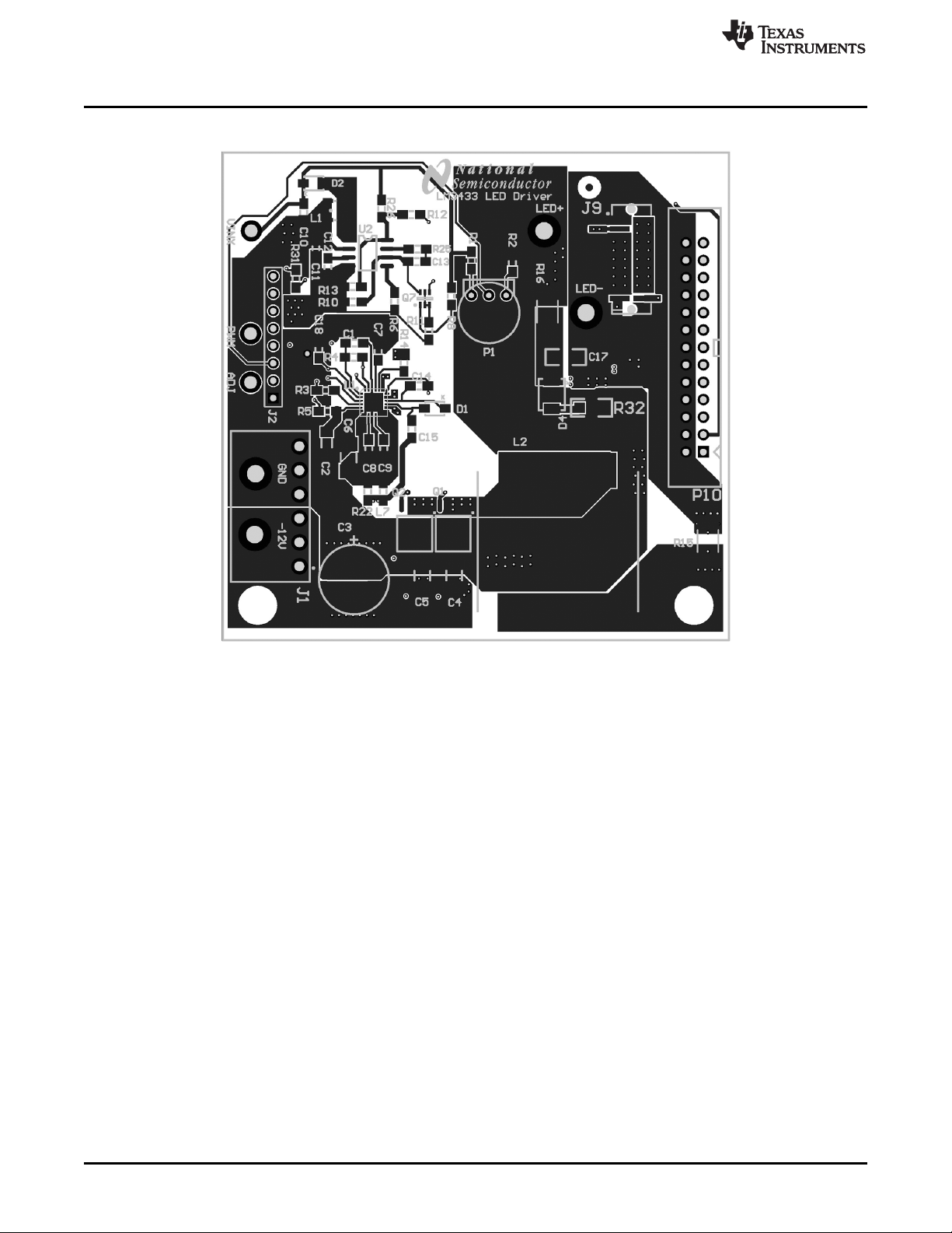
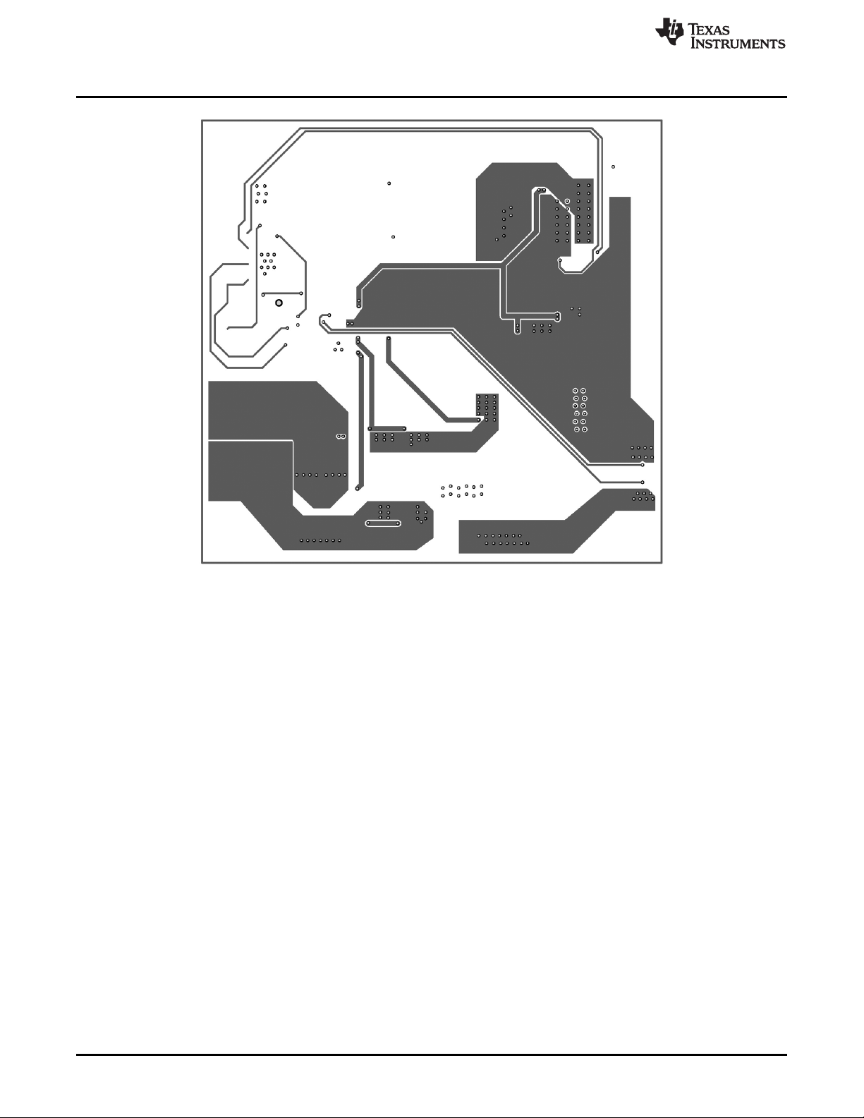
7 Layout
www.ti.com
Figure 7. Top Layer and Top Overlay
8
AN-1793 LM3433 4A to 20A LED Driver Evaluation Board SNVA327B–March 2008–Revised May 2013
Copyright © 2008–2013, Texas Instruments Incorporated
Submit Documentation Feedback
Page 9

www.ti.com
Layout
Figure 8. Upper Middle Layer
SNVA327B–March 2008–Revised May 2013 AN-1793 LM3433 4A to 20A LED Driver Evaluation Board
Submit Documentation Feedback
Copyright © 2008–2013, Texas Instruments Incorporated
9
Page 10
Layout
www.ti.com
Figure 9. Lower Middle Layer
10
AN-1793 LM3433 4A to 20A LED Driver Evaluation Board SNVA327B–March 2008–Revised May 2013
Copyright © 2008–2013, Texas Instruments Incorporated
Submit Documentation Feedback
Page 11
www.ti.com
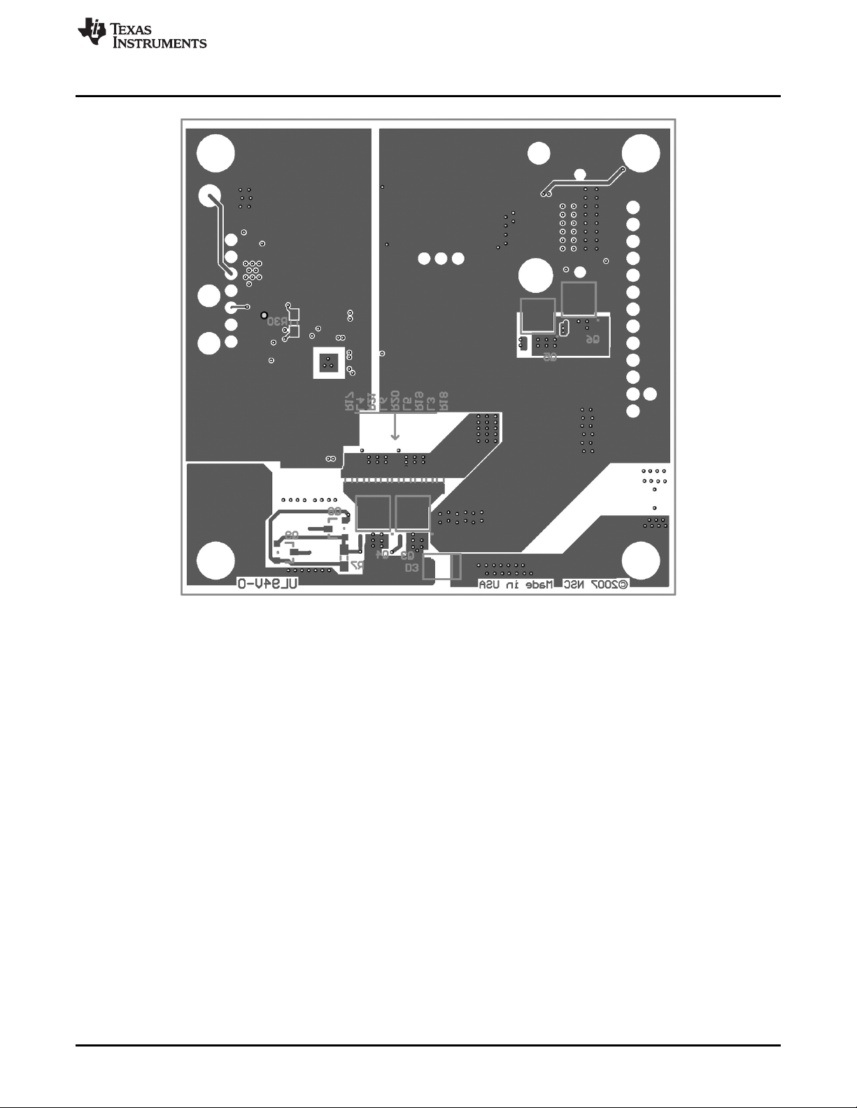
Layout
Figure 10. Bottom Layer and Bottom Overlay
SNVA327B–March 2008–Revised May 2013 AN-1793 LM3433 4A to 20A LED Driver Evaluation Board
Submit Documentation Feedback
Copyright © 2008–2013, Texas Instruments Incorporated
11
Page 12

IMPORTANT NOTICE
Texas Instruments Incorporated and its subsidiaries (TI) reserve the right to make corrections, enhancements, improvements and other
changes to its semiconductor products and services per JESD46, latest issue, and to discontinue any product or service per JESD48, latest
issue. Buyers should obtain the latest relevant information before placing orders and should verify that such information is current and
complete. All semiconductor products (also referred to herein as “components”) are sold subject to TI’s terms and conditions of sale
supplied at the time of order acknowledgment.
TI warrants performance of its components to the specifications applicable at the time of sale, in accordance with the warranty in TI’s terms
and conditions of sale of semiconductor products. Testing and other quality control techniques are used to the extent TI deems necessary
to support this warranty. Except where mandated by applicable law, testing of all parameters of each component is not necessarily
performed.
TI assumes no liability for applications assistance or the design of Buyers’ products. Buyers are responsible for their products and
applications using TI components. To minimize the risks associated with Buyers’ products and applications, Buyers should provide
adequate design and operating safeguards.
TI does not warrant or represent that any license, either express or implied, is granted under any patent right, copyright, mask work right, or
other intellectual property right relating to any combination, machine, or process in which TI components or services are used. Information
published by TI regarding third-party products or services does not constitute a license to use such products or services or a warranty or
endorsement thereof. Use of such information may require a license from a third party under the patents or other intellectual property of the
third party, or a license from TI under the patents or other intellectual property of TI.
Reproduction of significant portions of TI information in TI data books or data sheets is permissible only if reproduction is without alteration
and is accompanied by all associated warranties, conditions, limitations, and notices. TI is not responsible or liable for such altered
documentation. Information of third parties may be subject to additional restrictions.
Resale of TI components or services with statements different from or beyond the parameters stated by TI for that component or service
voids all express and any implied warranties for the associated TI component or service and is an unfair and deceptive business practice.
TI is not responsible or liable for any such statements.
Buyer acknowledges and agrees that it is solely responsible for compliance with all legal, regulatory and safety-related requirements
concerning its products, and any use of TI components in its applications, notwithstanding any applications-related information or support
that may be provided by TI. Buyer represents and agrees that it has all the necessary expertise to create and implement safeguards which
anticipate dangerous consequences of failures, monitor failures and their consequences, lessen the likelihood of failures that might cause
harm and take appropriate remedial actions. Buyer will fully indemnify TI and its representatives against any damages arising out of the use
of any TI components in safety-critical applications.
In some cases, TI components may be promoted specifically to facilitate safety-related applications. With such components, TI’s goal is to
help enable customers to design and create their own end-product solutions that meet applicable functional safety standards and
requirements. Nonetheless, such components are subject to these terms.
No TI components are authorized for use in FDA Class III (or similar life-critical medical equipment) unless authorized officers of the parties
have executed a special agreement specifically governing such use.
Only those TI components which TI has specifically designated as military grade or “enhanced plastic” are designed and intended for use in
military/aerospace applications or environments. Buyer acknowledges and agrees that any military or aerospace use of TI components
which have not been so designated is solely at the Buyer's risk, and that Buyer is solely responsible for compliance with all legal and
regulatory requirements in connection with such use.
TI has specifically designated certain components as meeting ISO/TS16949 requirements, mainly for automotive use. In any case of use of
non-designated products, TI will not be responsible for any failure to meet ISO/TS16949.
Products Applications
Audio www.ti.com/audio Automotive and Transportation www.ti.com/automotive
Amplifiers amplifier.ti.com Communications and Telecom www.ti.com/communications
Data Converters dataconverter.ti.com Computers and Peripherals www.ti.com/computers
DLP® Products www.dlp.com Consumer Electronics www.ti.com/consumer-apps
DSP dsp.ti.com Energy and Lighting www.ti.com/energy
Clocks and Timers www.ti.com/clocks Industrial www.ti.com/industrial
Interface interface.ti.com Medical www.ti.com/medical
Logic logic.ti.com Security www.ti.com/security
Power Mgmt power.ti.com Space, Avionics and Defense www.ti.com/space-avionics-defense
Microcontrollers microcontroller.ti.com Video and Imaging www.ti.com/video
RFID www.ti-rfid.com
OMAP Applications Processors www.ti.com/omap TI E2E Community e2e.ti.com
Wireless Connectivity www.ti.com/wirelessconnectivity
Mailing Address: Texas Instruments, Post Office Box 655303, Dallas, Texas 75265
Copyright © 2013, Texas Instruments Incorporated
 Loading...