

UC1838A
UC2838A
UC3838A
Magnetic Amplifier Controller
FEATURES
• Independent 1% Reference
• Two Uncommitted, Identical
Operational Amplifiers
• 100mA Reset Current Source
with –120V Capability
• 5V to 40V Analog Operation
• 5W DIL Package
10VCC
VREF
9
2.5V
REFERENCE
INV. IN
8E/A OUT
3INV. IN
6
7N.I. IN
2
1
N.I. IN
C/L OUT
C/L
E/A
3.5V
15 DR 1
16 DR 2
RESET
14
VM11
5 12 134
GND GND GND GND
201k5k
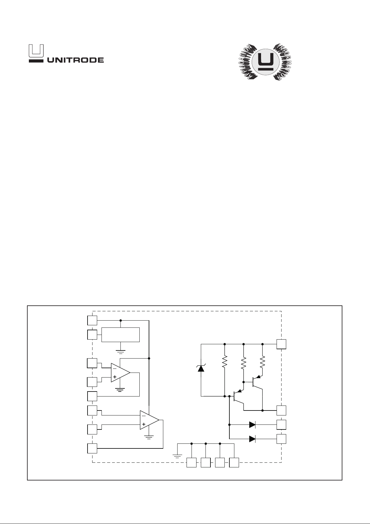
BLOCK DIAGRAM
04/99
UDG-97174
DESCRIPTION
The UC1838A family of magnetic amplifier controllers contains the circuitry to generate and amplify a low-level analog error signal along with a high voltage-compliant current source. This source will provide the reset current necessary
to enable a magnetic amplifier to regulate and control a power supply output in the
range of 2A to 20A.
By controlling the reset current to a magnetic amplifier, this device will define the
amount of volt-seconds the magnetic amplifier will block before switching to the
conducting state. Magnetic amplifiers are ideal for post-regulators for multiple-output power supplies where each output can be independently controlled with
efficiencies up to 99%. With a square or pulse-width-modulated input voltage, a
magnetic amplifier will block a portion of this input waveform, allowing just enough
to pass to provide a regulated output. With the UC1838A, only the magnetic amplifier coil, three diodes, and an output L-C filter are necessary to implement a complete closed-loop regulator.
The UC1838A contains a precision 2.5V reference, two uncommitted high-gain op
amps and a high-gain PNP-equivalent current source which can deliver up to
100mA of magnetic amplifier reset current and with –120 volt capability.
These devices are available in a plastic “bat-wing” DIP for operation over a –20°C
to +85°C temperature range and, with reduced power, in a hermetically sealed
cerdip for –55°C to +125°C operation.Surface mount versions are also available.
This improved “A”version replaced the non “A” version formerly introduced.
2
UC1838A
UC2838A
UC3838A
ABSOLUTE MAXIMUM RATINGS
Supply Voltage, V
CC
. . . . . . . . . . . . . . . . . . . . . . . . . . . . . . . . . . . . . . .
40V
Magnetic Amp. Source Voltage, V
M
. . . . . . . . . . . . . . . . . . . . . . . .
40V
Reset Output Voltage, V
R
. . . . . . . . . . . . . . . . . . . . . . . . . . . . . . .
–120V
Total Current Source Voltage, VM-V
R
. . . . . . . . . . . . . . . . . .
–140V
Amplifier Input Range . . . . . . . . . . . . . . . . . . . . . . –0.3V to V
CC
Reset Input Current, I
DR
. . . . . . . . . . . . . . . . . . . . . . . . . . . . . . . .
–10mA
Power Dissipation at TA= 25°C
Q, N, DP Package . . . . . . . . . . . . . . . . . . . . . . . . . . . . . . 2W
J, L Package. . . . . . . . . . . . . . . . . . . . . . . . . . . . . . . . . . . 1W
Power Dissipation at T (leads/case) = 25°C
Q, N, DP Package . . . . . . . . . . . . . . . . . . . . . . . . . . . . . . 5W
J, L Package. . . . . . . . . . . . . . . . . . . . . . . . . . . . . . . . . . . 2W
Operating Temperature Range. . . . . . . . . . . . –55°C to +125°C
Storage Temperature Range . . . . . . . . . . . . . –65°C to +150°C
Lead Temperature (Soldering, 10 sec) . . . . . . . . . . . . . . 300°C
Note: All voltages are with respect to ground pins. All currents
are positive into the specified terminal. Consult Packaging
section of Databook for thermal limitations and considerations
of package.
DR 216
15
14
13
12
11
10
9
1
2
3
4
5
6
7
8
DR 1
Reset
Gnd
Gnd
V
M
V
CC
V
REF
C/L Out
C/L N.I. In
C/L INV. In
Gnd
Gnd
E/A Inv.In
E/A N.I. In
E/A Out
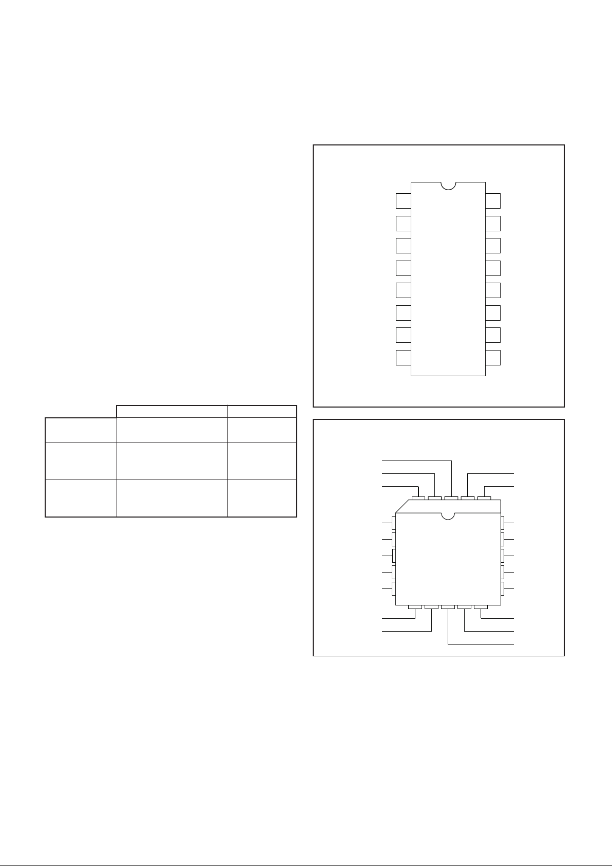
CONNECTION DIAGRAMS
DIL-16, SOIC-16 (TOP VIEW)
J or N Package, DP Package
3
18
17
16
N/C
122019
15
14
4
5
6
7
8
91110 12 13
C/L Out
C/L N.I. In
DR2
DR1
Reset
N/C
N/C
GND
V
M
C/L Inv. In
GND
N/C
N/C
E/A Inv. In
V
CC
V
REF
N/C
E/A N.I. In
E/A Out
PLCC-20, LCC-20 (TOP VIEW)
Q, L Packages
Note: All four ground pins must be connected to a common
ground
TEMPERATURE RANGE PACKAGE
UC1838AJ –55°C to +125°C Ceramic Dip
UC1838AL CLCC
UC2838ADP –20°C to +85°C Power SOIC
UC2838AN Plastic Dip
UC2838AQ PLCC
UC3838ADP 0°C to +70°C Power SOIC
UC3838AN Plastic Dip
UC3838AQ PLCC
ORDERING INFORMATION

3
UC1838A
UC2838A
UC3838A
ELECTRICAL CHARACTERISTICS:
Unless otherwise stated, these specifications apply for TA= –55°C to +125°C for the
UC1838A, –20°C to +85°C for the UC2838A, and 0°C to +70°C for the UC3838A, VCC= 20V, VM= 5V, TA=T
J
.
PARAMETER TEST CONDITIONS
UC1838A / UC2838A UC3838A UNITS
MIN TYP MAX MIN TYP MAX
Reference Section
Supply Current V
CC=VM
= 40V 4 8 4 8 mA
Reference Output T
A
= 25°C 2.47 2.5 2.53 2.45 2.5 2.55 V
Line Regulation V
CC
= 5 to 30V 1 5 1 10 mV
Load Regulation I
O
= 0 to –2mA 5 20 5 20 mV
Short Circuit Current V
REF
= 0V –30 –60 –30 –60 mA
Temperature Stability* Over Operating Temp. Range 15 25 10 25 mV
Amplifier Section (Each Amplifier)
Offset Voltage V
CM
= 2.5V 5 10 mV
Input Bias Current V
IN
= 0V –1 –1
µ
A
Input Offset Current 100 100 nA
Minimum Output Swing 0.4 18 0.4 18 V
Output Sink Current V
O
= 5V 1103011030mA
Output Source Current V
O
= 0V –1 –10 –20 –1 –10 –20 mA
A
VOL
VO= 1 to 11V 100 120 100 120 dB
C
MRR
VIN= 1 to 11V 70 80 70 80 dB
P
SRR
VCC= 10 to 20V 70 100 70 100 dB
Gain Bandwidth* 0.6 0.8 0.6 0.8 MHz
Reset Drive Section
Input Leakage V
DR
= 40V 10 10
µ
A
Output Leakage V
R
= –120V –100 –100
µ
A
Input Current I
R
= –50mA –1 –2 –1 –2 mA
Maximum Reset Current I
DR
= –3mA –100 –120 –200 –100 –120 –200 mA
Transconductance I
R
= –10 to –50mA .03 .042 .055 .03 .042 .055 A/V
* These parameters are guaranteed by design but not 100% tested in production.
TYPICAL APPLICATION
+12V, 4A output with switching frequency = 50 kHz.

4
UC1838A
UC2838A
UC3838A
APPLICATION INFORMATION
Figure 1. Amplifier open loop response.
Figure 2. Reset driver-input current.
Figure 5. Reset driver-input voltage.
Figure 3. Reset driver-output impedance. Figure 6. Reference temperature coefficient.
UNITRODE CORPORATION
7 CONTINENTAL BLVD. • MERRIMACK, NH 03054
TEL. (603) 424-2410 • FAX (603) 424-3460
Figure 4. Reset driver response.

IMPORTANT NOTICE
T exas Instruments and its subsidiaries (TI) reserve the right to make changes to their products or to discontinue
any product or service without notice, and advise customers to obtain the latest version of relevant information
to verify, before placing orders, that information being relied on is current and complete. All products are sold
subject to the terms and conditions of sale supplied at the time of order acknowledgement, including those
pertaining to warranty, patent infringement, and limitation of liability.
TI warrants performance of its semiconductor products to the specifications applicable at the time of sale in
accordance with TI’s standard warranty. T esting and other quality control techniques are utilized to the extent
TI deems necessary to support this warranty. Specific testing of all parameters of each device is not necessarily
performed, except those mandated by government requirements.
CERT AIN APPLICATIONS USING SEMICONDUCTOR PRODUCTS MAY INVOLVE POTENTIAL RISKS OF
DEATH, PERSONAL INJURY, OR SEVERE PROPERTY OR ENVIRONMENTAL DAMAGE (“CRITICAL
APPLICATIONS”). TI SEMICONDUCTOR PRODUCTS ARE NOT DESIGNED, AUTHORIZED, OR
WARRANTED TO BE SUITABLE FOR USE IN LIFE-SUPPORT DEVICES OR SYSTEMS OR OTHER
CRITICAL APPLICATIONS. INCLUSION OF TI PRODUCTS IN SUCH APPLICA TIONS IS UNDERSTOOD T O
BE FULLY AT THE CUSTOMER’S RISK.
In order to minimize risks associated with the customer’s applications, adequate design and operating
safeguards must be provided by the customer to minimize inherent or procedural hazards.
TI assumes no liability for applications assistance or customer product design. TI does not warrant or represent
that any license, either express or implied, is granted under any patent right, copyright, mask work right, or other
intellectual property right of TI covering or relating to any combination, machine, or process in which such
semiconductor products or services might be or are used. TI’s publication of information regarding any third
party’s products or services does not constitute TI’s approval, warranty or endorsement thereof.
Copyright 1999, Texas Instruments Incorporated
 Loading...