

Page 1

1 Introduction
The TPS8804EVM is used to evaluate the TPS8804 smoke and CO detector analog front end (AFE) and
power management IC. The EVM allows for easy connection from the TPS8804 to a user-supplied
photoelectric chamber and carbon monoxide sensor. The TPS8804 GUI interfaces with the EVM to quickly
evaluate the photo amplifier, LED driver, and CO amplifier performance, and other blocks with the register
map. For a more thorough evaluation, an external microcontroller can be connected to the TPS8804EVM
to create a smoke detection system.
1.1 Applications
• Smoke and CO detectors
1.2 Features
• Dual LED drivers for blue and IR LEDs
• Wide bandwidth, low offset photodiode amplifier
• Ultra-low power CO transimpedance amplifier
• LDOs for internal analog blocks and external microcontroller
• Single buffered analog output AMUX for CO and photo signals
• Serial interface for configuring amplifiers, drivers, regulators
• SLC interface for power line communication
• Under-voltage, over-temperature fault monitors
• Wide input voltage range for flexible power supply configuration
User's Guide
SLVUBT6–October 2019
Using the TPS8804EVM
1.3 Recommended Equipment
• 4.5-V to 15.5-V power supply capable of 100mA
• USB2ANY™ interface adaptor
• TPS880x GUI software
– Installation files are available in the TPS8804EVM product folder
• Multimeter for measuring regulator voltages and CO amplifier output
• Oscilloscope for measuring photodiode signal pulse shape
2 Setup
Specific connections on the TPS8804EVM board require configuration before starting the evaluation.
2.1 Sensor Connections
TI recommends connecting a photoelectric smoke chamber and CO sensor to the TPS8804EVM for the
evaluation. The TPS8804EVM has a built-in photodiode (D7), blue LED (D8), and IR LED (D6) for
functional testing. These components can be de-soldered in order to connect a photoelectric chamber
photodiode, IR LED, and/or blue LED its place. Ensure the photodiode wires are kept short to preserve
signal integrity.
SLVUBT6–October 2019
Submit Documentation Feedback
Copyright © 2019, Texas Instruments Incorporated
Using the TPS8804EVM
1
Page 2
Setup
The CO sensor is connected to J17 screw terminals with the sensor counter terminal tied to AGND.
2.2 Jumper and Switch Configurations
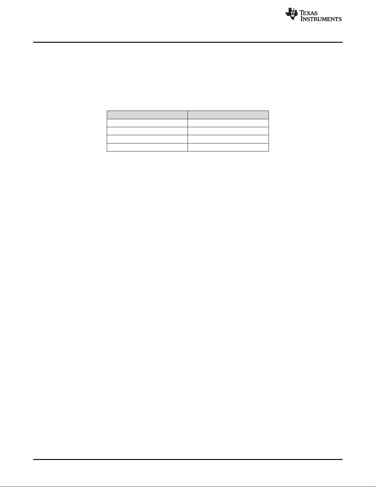
The S1 switch position determines the VMCU voltage at power-up. Ensure that only one S1 sub-switch is
in the ON position. Table 1 displays the VMCU voltage corresponding with each S1 switch position. For
proper operation with the USB2ANY adapter, set VMCU to 3.3 V with sub-switch 4.
Table 1. VMCU Power-up Voltage
S1 Switch Position VMCU
1 1.5V
2 1.8V
3 2.5V
4 3.3V
The J2 jumper connects VSLC to VCC. A single supply connected to VCC powers the entire EVM with the
jumper connected.
The J6 jumper selects the I2C device address. Connect J6 to the AGND position to set the address to
0x3F. Connect J6 to the VMCU position to set the address to 0x2A. The GUI is compatible with both
options and defaults to 0x2A.
www.ti.com
2
Using the TPS8804EVM
Copyright © 2019, Texas Instruments Incorporated
SLVUBT6–October 2019
Submit Documentation Feedback
Page 3
www.ti.com
Setup
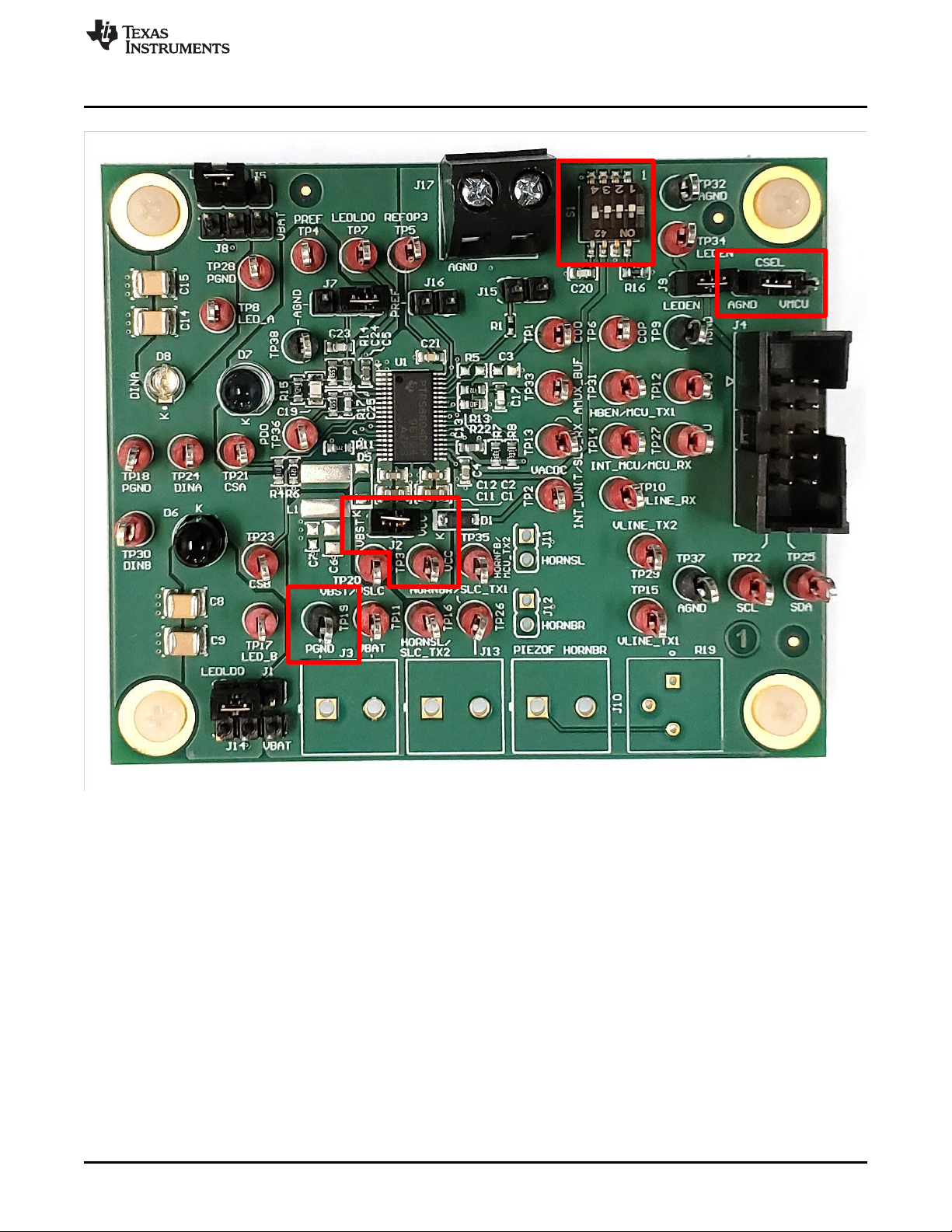
2.3 Power Connection
Connect the power supply to VCC and PGND. Set the power supply to 5 V, 100 mA. Enable the power
supply and measure the voltage on VMCU (TP27) to ensure it is operating at the voltage option selected
by S1:
• 1.5 V
• 1.8 V
• 2.5 V
• 3.3 V
See Table 1 for more information on the initial VMCU voltage.
SLVUBT6–October 2019
Submit Documentation Feedback
Figure 1. Switch, Jumper, and Power Connections
Copyright © 2019, Texas Instruments Incorporated
Using the TPS8804EVM
3
Page 4
Setup
2.4 USB2ANY Connection
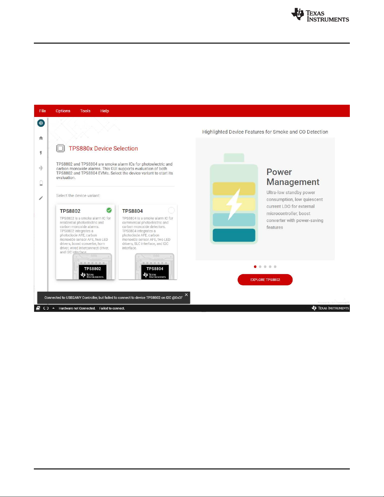
Use a USB cable to connect the USB2ANY adapter to a computer with the TPS880x GUI installed. Open
the TPS880x GUI and verify the USB2ANY adapter is recognized (see Figure 2). With the EVM powered,
connect the USB2ANY adapter to the EVM using the USB2ANY adapter 10-pin ribbon cable. Click
EXPLORE TPS8804EVM then QUICK START and select the device address corresponding to the J6
jumper (see Section 2.2). Send the test command to verify the EVM, USB2ANY adapter, and GUI
software are all connected.
www.ti.com
Figure 2. TPS880x GUI Connected to USB2ANY Adapter
4
Using the TPS8804EVM
Copyright © 2019, Texas Instruments Incorporated
SLVUBT6–October 2019
Submit Documentation Feedback
Page 5

www.ti.com
Analog Evaluation
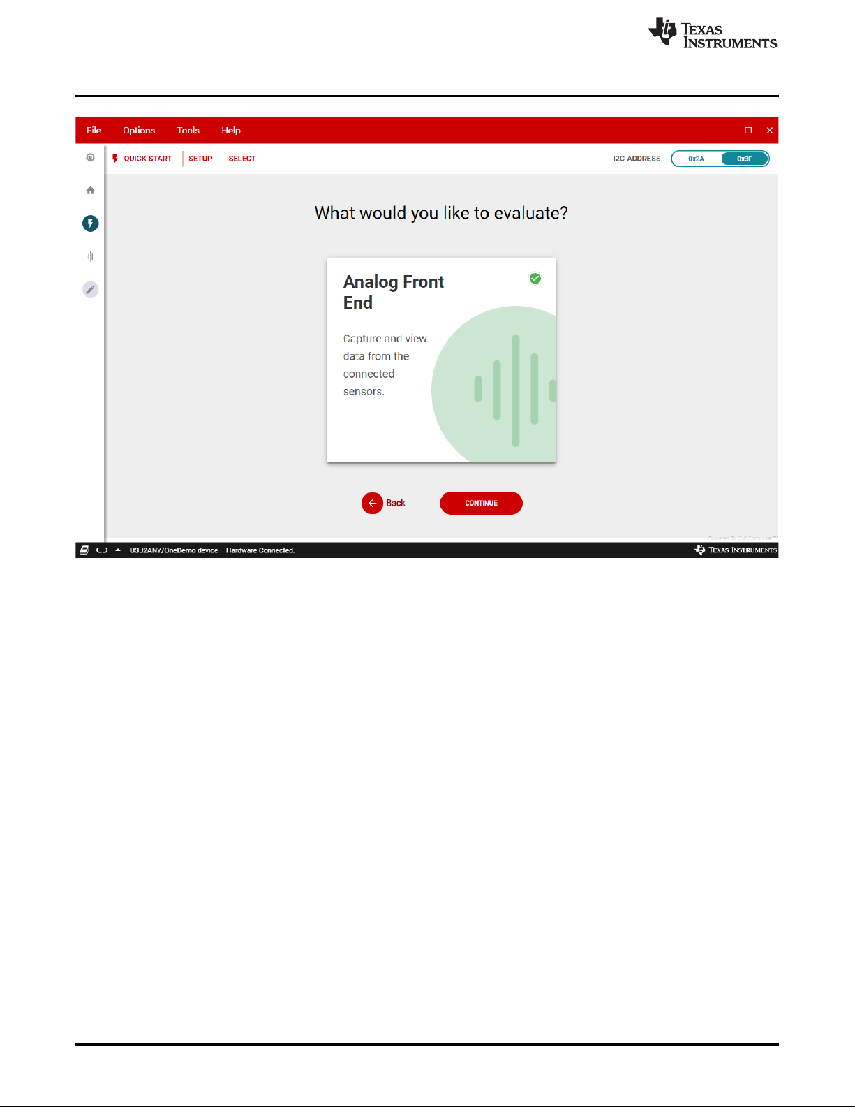
3 Analog Evaluation
Click START EVALUATION and select the feature to evaluate. The Analog Front End section guides the
CO AFE and photo AFE evaluation. Enter the register map to evaluate the other blocks in the TPS8804
device.
Figure 3. Test Command Successful
SLVUBT6–October 2019
Submit Documentation Feedback
Copyright © 2019, Texas Instruments Incorporated
Using the TPS8804EVM
5
Page 6
Analog Evaluation
www.ti.com
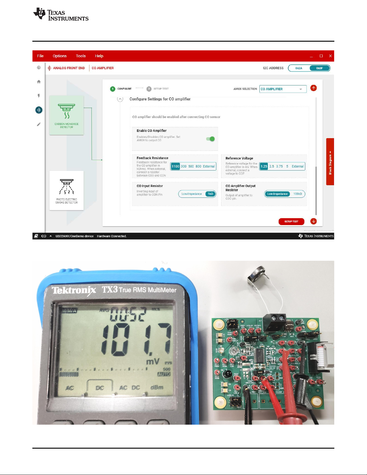
3.1 CO AFE Evaluation
If a CO sensor is available, connect it to the J17 terminal block. Select the feedback resistance and
reference voltage in the GUI software. The TPS8804EVM default configuration uses the internal resistors
and references. To use an external feedback resistor, solder a resistor to R5. To use an external input
resistor, replace the R1 0-Ω resistor with the required input resistance. The output resistor filters the CO
amplifier output when a capacitor is installed on C3.
Set the AMUX SELECTION to CO AMPLIFIER. Enable the CO amplifier and measure the voltage on
AMUX_BUF.
Figure 4. Evaluation Selection Menu
6
Using the TPS8804EVM
Copyright © 2019, Texas Instruments Incorporated
SLVUBT6–October 2019
Submit Documentation Feedback
Page 7
www.ti.com
Analog Evaluation
Figure 5. CO Amplifier Settings
SLVUBT6–October 2019
Submit Documentation Feedback
Figure 6. Clean Air CO Amplifier Output
Copyright © 2019, Texas Instruments Incorporated
Using the TPS8804EVM
7
Page 8
Analog Evaluation
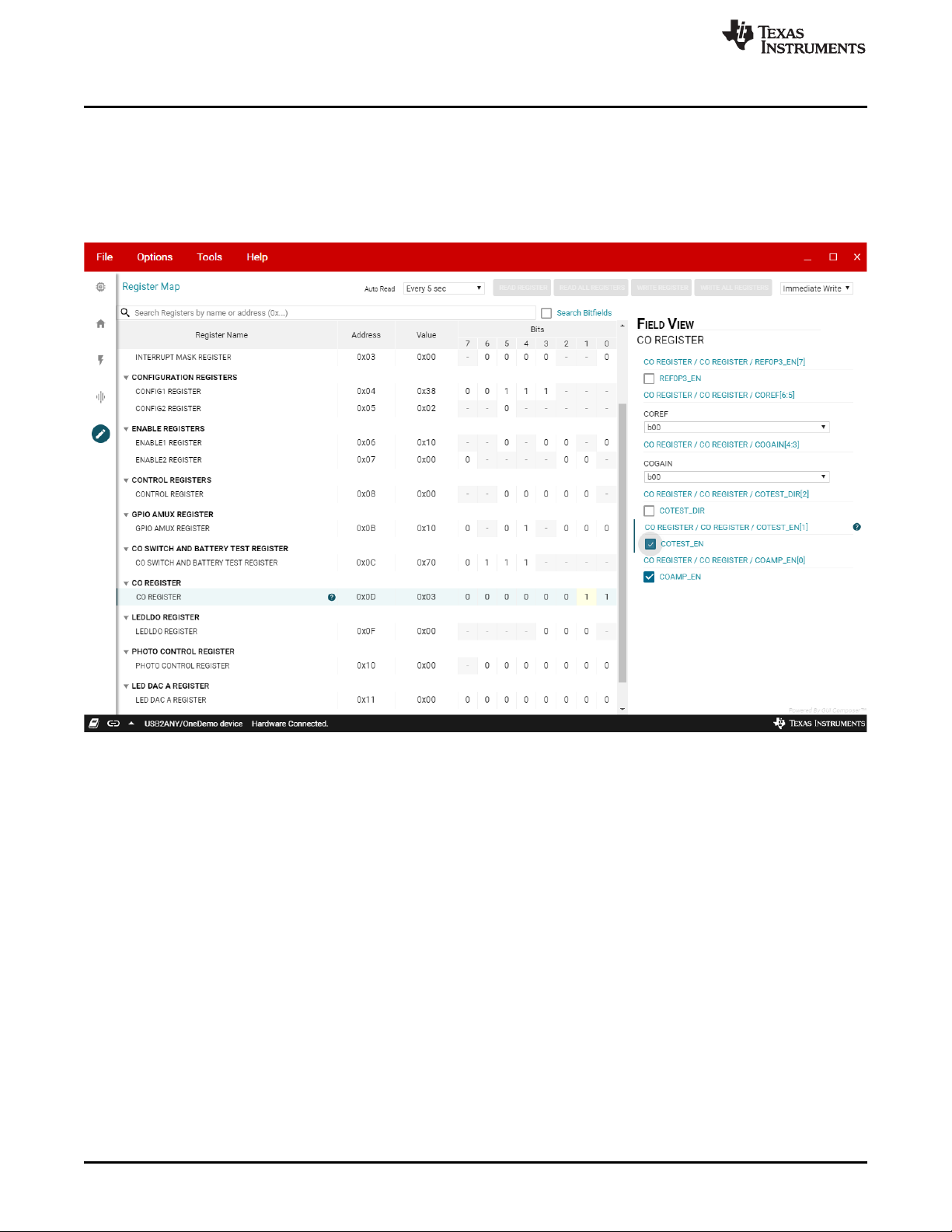
3.1.1 CO Connectivity Test
A simple test confirms that the CO sensor is connected to the EVM. Remove the shunt connected to J7
and connect a shunt to J15 and J16. Write COTEST_EN = 1 and measure the pulse shape on
AMUX_BUF using an oscilloscope. When COTEST_EN = 1, the PREF pin is pulled low and injects charge
into the CO sensor and amplifier. The AMUX pulse shape is different if the CO sensor is disconnected.
Write COTEST_EN = 0, remove the J15 and J16 shunts, and connect the J7 shunt when finished.
www.ti.com
Figure 7. COTEST_EN Register Bit
8
Using the TPS8804EVM
Copyright © 2019, Texas Instruments Incorporated
SLVUBT6–October 2019
Submit Documentation Feedback
Page 9

www.ti.com
Analog Evaluation
Figure 8. CO Connectivity Test without Sensor
SLVUBT6–October 2019
Submit Documentation Feedback
Copyright © 2019, Texas Instruments Incorporated
Using the TPS8804EVM
9
Page 10

Analog Evaluation
www.ti.com
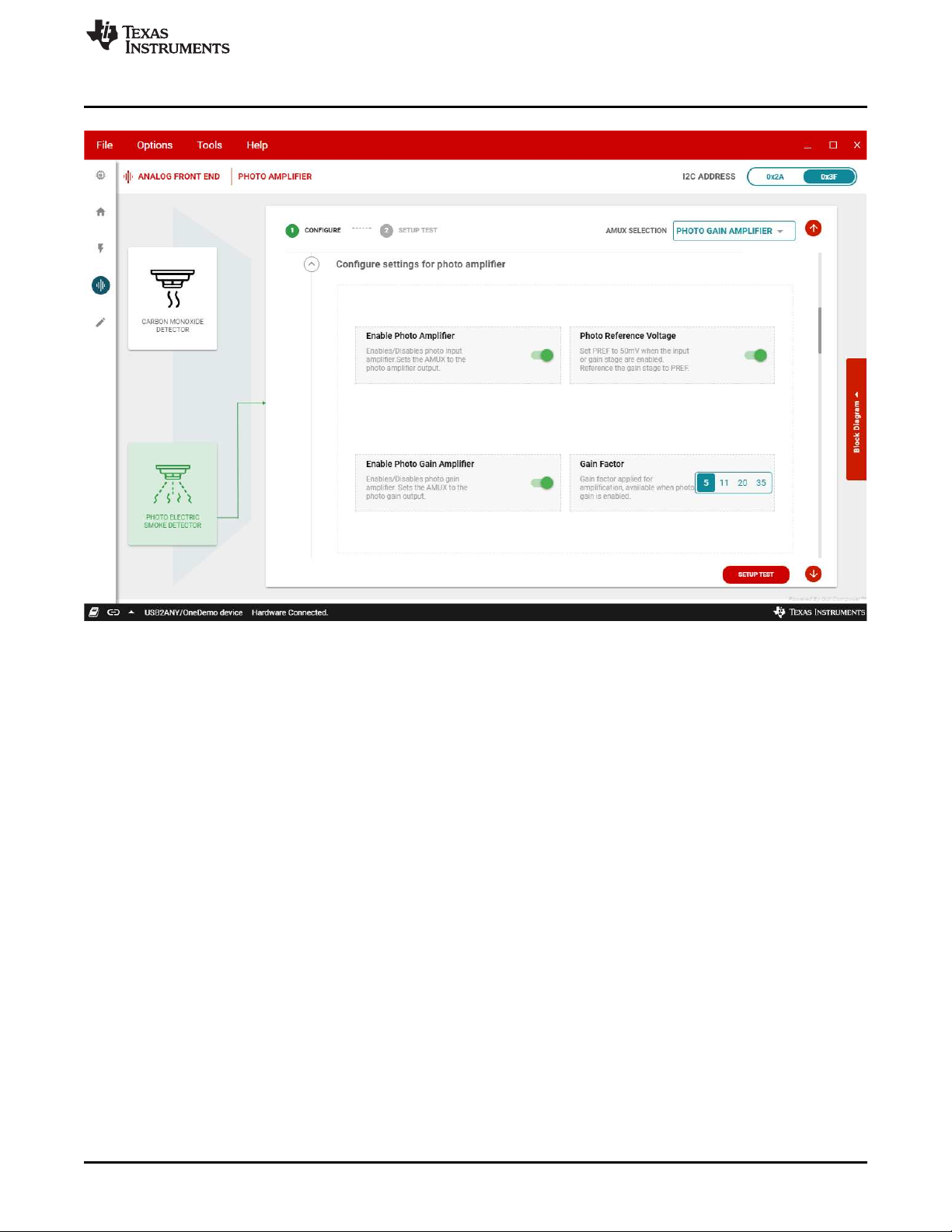
3.2 Photo AFE Evaluation
Connect the photoelectric chamber to the EVM. If a photoelectric chamber is not available, place a box
over the EVM to block ambient light and reflect the EVM LED light into the photodiode when testing the
photo AFE.
Enable the photo amplifier, photo gain amplifier, and set the AMUX SELECTION to PHOTO GAIN
AMPLIFIER. Select the photo reference on the EVM with jumper J7 and enable the photo reference
voltage if the reference is set to PREF. Set the gain factor to the required value. If no extra gain is
required, set the AMUX SELECTION to PHOTO AMPLIFIER.
Figure 9. CO Connectivity Test with Sensor
10
Using the TPS8804EVM
Copyright © 2019, Texas Instruments Incorporated
SLVUBT6–October 2019
Submit Documentation Feedback
Page 11
www.ti.com
Analog Evaluation
Figure 10. Photo Amplifier Settings
Configure the power to the LEDs. By default, LED A and LED B are connected to LEDLDO. Use the J1,
J5, J8, and J14 jumpers to select which supply powers each LED. Enable the LEDLDO if it powers either
LED.
SLVUBT6–October 2019
Submit Documentation Feedback
Copyright © 2019, Texas Instruments Incorporated
Using the TPS8804EVM
11
Page 12

Analog Evaluation
www.ti.com
Figure 11. LED Power Supply Settings
Configure the PWM pulse settings for the LED driver. The default setting 201 ms pulse rate and 1 ms
pulse width sufficiently tests the LED driver. This setting controls the PWM signal from the USB2ANY
adapter to the EVM.
Configure the LED current for each driver. The default EVM CSA resistance is 10 Ω and the default EVM
CSB resistance is 1.3 Ω. These resistors can be switched on the EVM to change the LED current and
temperature compensation. Set the DAC voltage to fine tune the LED current. Set the temperature
coefficient to the required setting. Click SETUP TEST after configuring the photo amplifier, LED power
supply, and LED driver.
12
Using the TPS8804EVM
Copyright © 2019, Texas Instruments Incorporated
SLVUBT6–October 2019
Submit Documentation Feedback
Page 13

www.ti.com
Analog Evaluation
Figure 12. LED Driver Settings
Select the LED to be tested. Enable the LED PWM to send the PWM signal to the LEDEN pin. Enable
LEDPIN_EN to control the LED driver using the LEDEN pin. Place a box over the EVM if the EVM LEDs
and photodiode are used to block ambient light and reflect the LED light into the photodiode.
Use an oscilloscope to measure the LED current, photo input amplifier, and photo gain amplifier signals.
Probe LEDEN to measure the LED control signal. Probe CSA or CSB to measure the LED driver current.
Probe PDO to measure the photo input stage amplifier. Probe AMUX_BUF to measure the photo gain
stage amplifier.
SLVUBT6–October 2019
Submit Documentation Feedback
Copyright © 2019, Texas Instruments Incorporated
Using the TPS8804EVM
13
Page 14

Analog Evaluation
www.ti.com
14
Using the TPS8804EVM
Figure 13. EVM Photo Measurement Probe Configuration
Copyright © 2019, Texas Instruments Incorporated
SLVUBT6–October 2019
Submit Documentation Feedback
Page 15

www.ti.com
Analog Evaluation
Figure 14. LED A Signals
SLVUBT6–October 2019
Submit Documentation Feedback
Copyright © 2019, Texas Instruments Incorporated
Using the TPS8804EVM
15
Page 16

Analog Evaluation
www.ti.com
Figure 15. LED B Signals
16
Using the TPS8804EVM
Copyright © 2019, Texas Instruments Incorporated
SLVUBT6–October 2019
Submit Documentation Feedback
Page 17

www.ti.com
Analog Evaluation
3.3 Register Map
Use the register map to evaluate other blocks in the TPS8804. Use the search to find register bits that
correspond to a certain block or function. Load and save register map configurations in the File menu.
Click the question mark icon (?) to display more information about the selected register or bits.
Figure 16. Photo Signal with Photo Chamber
SLVUBT6–October 2019
Submit Documentation Feedback
Copyright © 2019, Texas Instruments Incorporated
Using the TPS8804EVM
17
Page 18

Analog Evaluation
www.ti.com
Figure 17. Register Map Search Function
18
Using the TPS8804EVM
Copyright © 2019, Texas Instruments Incorporated
SLVUBT6–October 2019
Submit Documentation Feedback
Page 19

www.ti.com
4 Board Layout
Board Layout
SLVUBT6–October 2019
Submit Documentation Feedback
Figure 18. TPS8804EVM Top Layer Board Layout
Copyright © 2019, Texas Instruments Incorporated
Using the TPS8804EVM
19
Page 20

Board Layout
www.ti.com
20
Using the TPS8804EVM
Figure 19. TPS8804EVM Bottom Layer Board Layout
Copyright © 2019, Texas Instruments Incorporated
SLVUBT6–October 2019
Submit Documentation Feedback
Page 21

www.ti.com
5 Schematic and Bill of Materials
5.1 Schematic
Schematic and Bill of Materials
5.2 Bill of Materials
REF DES QTY VALUE DESCRIPTION SIZE PART NUMBER
PCB1 1 Printed Circuit Board TPS880x
C1, C11 2 4.7 µF Capacitor, ceramic, 4.7 µF, 25 V, ±10%, X7R, 0805 0805
C2, C12 2 0.1 µF Capacitor, ceramic, 0.1 µF, 25 V, ±5%, X7R, 0603 0603 06033C104JAT2A
C4, C13, C16,
C18
C5 1 1 µF Capacitor, ceramic, 1 µF, 16 V, ±10%, X7R, 0603 0603 EMK107B7105KA-T
C8, C9, C14,
C15
C10 1 100 pF Capacitor, ceramic, 100 pF, 16 V, ±10%, X7R, 0402 0402 0402YC101KAT2A
C17, C20 2 330 pF Capacitor, ceramic, 330 pF, 50 V, ±10%, X7R, 0603 0603
C19 1 7 pF Capacitor, ceramic, 7 pF, 50 V, ±7%, C0G/NP0, 0805 0805
C21 1 1000 pF Capacitor, ceramic, 1000 pF, 50 V, ±10%, X7R, 0603 0603
Figure 20. TPS8804EVM Schematic
Table 2. Bill of Materials
4 1 µF Capacitor, ceramic, 1 µF, 16 V, ±10%, X5R, 0603 0603
4 47 µF Capacitor, ceramic, 47 µF, 16 V, ±20%, X6S, 1210 1210
C2012X7R1E475K1
25AB
C0603C105K4PAC
TU
GRM32EC81C476M
E15L
C0603C331K5RAC
TU
CC0805DRNP09BN
7R0
C0603X102K5RAC
TU
SLVUBT6–October 2019
Submit Documentation Feedback
Copyright © 2019, Texas Instruments Incorporated
Using the TPS8804EVM
21
Page 22

Schematic and Bill of Materials
REF DES QTY VALUE DESCRIPTION SIZE PART NUMBER
C23 1 100 pF
C24, C25 2 10 pF
D1, D2, D3 3 100 V Diode, Switching, 100 V, 0.15 A, SOD-123 SOD-123 1N4148W-TP
D4 1 18 V Diode, Zener, 18 V, 225 mW, SOT-23 SOT-23 BZX84C18LT1G
D6 1 Infrared LED, Infrared, TH D5.5 mm SFH 4556
D7 1 Silicon PIN Photodiode, TH D5.7×H9 mm SFH 213
D8 1 Blue LED, Blue, TH D3.1 mm LTL1CHTBK4
H1, H2, H3, H4 4
H5, H6, H7, H8 4 Standoff, Hex, 0.5"L #4-40 Nylon Standoff 1902C
J1, J5, J6, J7,
J8, J14
J2, J9, J15,
J16
J4 1 Header (shrouded), 100mil, 5×2, Gold, TH
J17 1 Terminal Block, 5.08 mm, 2×1, TH
LBL1 1
Q1, Q2 2 65 V Transistor, NPN, 65 V, 0.1 A, SOT-23 SOT-23 BC846BLT1G
R1 1 0 Resistor, 0, 5%, 0.063 W, 0402 0402 RC0402JR-070RL
R2 1 10.0 kΩ Resistor, 10.0 k, .1%, .0625 W, 0402 0402 RT0402BRD0710KL
R3 1 100 kΩ Resistor, 100 k, 0.1%, 0.1 W, 0603 0603 RG1608P-104-B-T5
R4 1 10.0 Ω Resistor, 10.0, 0.5%, 0.1 W, 0603 0603 RT0603DRE0710RL
R6 1 1.30 Ω Resistor, 1.30, 0.5%, 0.1 W, 0603 0603 RT0603DRE071R3L
R7, R8 2 33 kΩ Resistor, 33 k, 5%, 0.1 W, AEC-Q200 Grade 0, 0603 0603
R9, R10 2 1.0 kΩ
R11 1 2.4 MΩ
R12, R21 2 470 Ω
R13 1 4.7 kΩ Resistor, 4.7 k, 5%, 0.1 W, AEC-Q200 Grade 0, 0603 0603
R14, R17 2 1.5 MΩ
R15 1 470 kΩ Resistor, 470 k, 0.5%, 0.1 W, 0603 0603
R16 1 620 Ω Resistor, 620, 1%, 0.1 W, 0603 0603
R22, R23 2 10MΩ Resistor, 10 M, 5%, 0.1 W, AEC-Q200 Grade 0, 0603 0603
S1 1 Switch, Slide, SPST 4 poles, SMT
SH-J1, SH-J2,
SH-J3, SH-J4,
SH-J7, SH-J8
6 Header, 2.54 mm, 3×1, Tin, TH
4 Header, 2.54 mm, 2×1, Tin, TH
6 1×2 Shunt, 100mil, Flash Gold, Black
Table 2. Bill of Materials (continued)
Capacitor, ceramic, 100 pF, 50 V, ±5%, C0G/NP0,
0603
Capacitor, ceramic, 10 pF, 50 V, ±5%, C0G/NP0,
0603
Machine Screw, Round, #4-40 × 1/4, Nylon, Philips
panhead
Thermal Transfer Printable Labels, 0.650" W ×
0.200" H - 10,000 per roll
Resistor, 1.0 k, 5%, 0.063 W, AEC-Q200 Grade 0,
0402
Resistor, 2.4 M, 5%, 0.1 W, AEC-Q200 Grade 0,
0603
Resistor, 470, 5%, 0.063 W, AEC-Q200 Grade 0,
0402
Resistor, 1.5 M, 5%, 0.1 W, AEC-Q200 Grade 0,
0603
0603
0603
Screw
Header, 2.54
mm, 3×1, TH
Header, 2.54
mm, 2×1, TH
5×2 Shrouded
header
Terminal
Block, 5.08
mm, 2×1, TH
PCB Label
0.650 × 0.200
inch
0402
0603
0402
0603
SW, SMT Half
Pitch 4SPST,
5.8×2.7×6.25
mm
Closed Top
100mil Shunt
www.ti.com
885012006057
06035A100JAT2A
NY PMS 440 0025
PH
22284033
22284023
5103308-1
039544-3002
THT-14-423-10
CRCW060333K0JN
EA
CRCW04021K00JN
ED
CRCW06032M40JN
EA
CRCW0402470RJN
ED
CRCW06034K70JN
EA
CRCW06031M50JN
EA
RT0603DRE07470K
L
RC0603FR07620RL
CRCW060310M0JN
EA
218-4LPST
SPC02SYAN
22
Using the TPS8804EVM
SLVUBT6–October 2019
Submit Documentation Feedback
Copyright © 2019, Texas Instruments Incorporated
Page 23

www.ti.com
Schematic and Bill of Materials
Table 2. Bill of Materials (continued)
REF DES QTY VALUE DESCRIPTION SIZE PART NUMBER
TP1, TP2,
TP3, TP4,
TP5, TP6,
TP7, TP8,
TP10, TP12,
TP13, TP14,
TP15, TP16,
TP17, TP18,
TP20, TP21,
TP22, TP23,
TP24, TP25,
TP26, TP27,
TP28, TP29,
TP30, TP31,
TP33, TP34,
TP35, TP36
TP9, TP19,
TP32, TP37,
TP38
U1 1 TPS8804DCP, DCP0038A (HTSSOP-38) DCP0038A TPS8804DCP
C3 0 0.22 µF Capacitor, ceramic, 0.22 µF, 16 V, ±10%, X7R, 0603 0603 885012206048
C6 0 4.7 µF Capacitor, ceramic, 4.7 µF, 25 V, ±10%, X7R, 0805 0805
C7 0 0.1 µF Capacitor, ceramic, 0.1 µF, 25 V, ±5%, X7R, 0603 0603 06033C104JAT2A
C22 0 1000 pF Capacitor, ceramic, 1000 pF, 50 V, ±10%, X7R, 0603 0603
D5 0 20 V Diode, Schottky, 20 V, 0.5 A, SOD-123 SOD-123 MBR0520LT1G
FID1, FID2,
FID3, FID4,
FID5, FID6
J3, J10, J13 0 Terminal Block, 5.08 mm, 2×1, TH
J11, J12 0 Header, 2.54 mm, 2×1, Tin, TH
L1 0 33 µH
R5, R20 0 1.00 MΩ
R18 0 5.6 MΩ
R19 0 500 kΩ Trimmer, 500k ohm, 0.5W, TH
SH-J5, SH-J6 0 1 × 2 Shunt, 100mil, Flash Gold, Black
TP11 0 Test Point, Multipurpose, Red, TH
32 Test Point, Multipurpose, Red, TH
5 Test Point, Multipurpose, Black, TH
0 Fiducial mark. There is nothing to buy or mount. N/A
Inductor, Drum Core, Ferrite, 33 uH, 0.7 A, 0.38 ohm,
SMD
Resistor, 1.00 M, 1%, 0.1 W, AEC-Q200 Grade 0,
0603
Resistor, 5.6 M, 5%, 0.1 W, AEC-Q200 Grade 0,
0603
Red
Multipurpose
Testpoint
Black
Multipurpose
Testpoint
Terminal
Block, 5.08
mm, 2×1, TH
Header, 2.54
mm, 2 × 1, TH
5×3×4.8 mm
0603
0603
375×190×375
mil
Closed Top
100mil Shunt
Red
Multipurpose
Testpoint
5010
5011
C2012X7R1E475K1
25AB
C0603X102K5RAC
TU
N/A
039544-3002
22284023
SDR0503-330KL
CRCW06031M00FK
EA
CRCW06035M60JN
EA
3386P-1-504LF
SPC02SYAN
5010
SLVUBT6–October 2019
Submit Documentation Feedback
Copyright © 2019, Texas Instruments Incorporated
Using the TPS8804EVM
23
Page 24

IMPORTANT NOTICE AND DISCLAIMER
TI PROVIDES TECHNICAL AND RELIABILITY DATA (INCLUDING DATASHEETS), DESIGN RESOURCES (INCLUDING REFERENCE
DESIGNS), APPLICATION OR OTHER DESIGN ADVICE, WEB TOOLS, SAFETY INFORMATION, AND OTHER RESOURCES “AS IS”
AND WITH ALL FAULTS, AND DISCLAIMS ALL WARRANTIES, EXPRESS AND IMPLIED, INCLUDING WITHOUT LIMITATION ANY
IMPLIED WARRANTIES OF MERCHANTABILITY, FITNESS FOR A PARTICULAR PURPOSE OR NON-INFRINGEMENT OF THIRD
PARTY INTELLECTUAL PROPERTY RIGHTS.
These resources are intended for skilled developers designing with TI products. You are solely responsible for (1) selecting the appropriate
TI products for your application, (2) designing, validating and testing your application, and (3) ensuring your application meets applicable
standards, and any other safety, security, or other requirements. These resources are subject to change without notice. TI grants you
permission to use these resources only for development of an application that uses the TI products described in the resource. Other
reproduction and display of these resources is prohibited. No license is granted to any other TI intellectual property right or to any third
party intellectual property right. TI disclaims responsibility for, and you will fully indemnify TI and its representatives against, any claims,
damages, costs, losses, and liabilities arising out of your use of these resources.
TI’s products are provided subject to TI’s Terms of Sale (www.ti.com/legal/termsofsale.html) or other applicable terms available either on
ti.com or provided in conjunction with such TI products. TI’s provision of these resources does not expand or otherwise alter TI’s applicable
warranties or warranty disclaimers for TI products.
Mailing Address: Texas Instruments, Post Office Box 655303, Dallas, Texas 75265
Copyright © 2019, Texas Instruments Incorporated
 Loading...