


www.ti.com
Table of Contents
User’s Guide
TPS659xx Application Customization Tool
Robert Almendarez
ABSTRACT
This document describes the functionality of the TPS659xx Application Customization Tool from Texas
Instruments. This tool can be used for generating configuration images for the host controller, for generating
configuration images for external flash memory and for debugging the TPS659xx device.
Table of Contents
1 Getting Started........................................................................................................................................................................3
1.1 Related Documents............................................................................................................................................................3
1.2 Hardware............................................................................................................................................................................3
1.3 Software............................................................................................................................................................................. 3
1.4 Installation and Launch...................................................................................................................................................... 3
1.5 Features of the TPS659xx Application Customization Tool............................................................................................... 9
2 Using the TPS659xx Application Customization Tool.......................................................................................................10
2.1 Default Application Customization Tool Start Page..........................................................................................................10
2.2 Beginning a New Project..................................................................................................................................................12
2.3 Loading and saving configuration settings as a Project File............................................................................................ 15
2.4 Importing configuration settings from a Project File......................................................................................................... 16
2.5 Loading an updated base firmware image....................................................................................................................... 16
2.6 Changing the adapter settings to connect to the device.................................................................................................. 17
2.7 Importing Configuration Settings from a TPS659xx......................................................................................................... 19
2.8 Exporting project configuration settings as a JSON file................................................................................................... 19
2.9 Loading Configuration Image Onto a TPS659xx..............................................................................................................21
2.10 Loading Configuration Image onto a TPS659xx device's RAM......................................................................................22
2.11 Using the Debug Mode...................................................................................................................................................23
2.12 Miscellaneous Features................................................................................................................................................. 32
3 Using the Aardvark® ............................................................................................................................................................35
3.1 Software and Driver Installation....................................................................................................................................... 35
3.2 Connecting Aardvark® to TPS659xx-EVM....................................................................................................................... 36
List of Figures
Figure 1-1. Installation License Agreement................................................................................................................................. 4
Figure 1-2. File Path for Installation Files.................................................................................................................................... 4
Figure 1-3. File Path for Start-Menu Shortcut..............................................................................................................................5
Figure 1-4. Miscellaneous Installation Options............................................................................................................................ 5
Figure 1-5. Installation Summary.................................................................................................................................................6
Figure 1-6. FTDI Driver Extraction...............................................................................................................................................6
Figure 1-7. FTDI Driver Installation..............................................................................................................................................7
Figure 1-8. License Agreement................................................................................................................................................... 7
Figure 1-9. Completed Driver Installation.................................................................................................................................... 8
Figure 1-10. Completed Tool Installation..................................................................................................................................... 8
Figure 2-1. Start Window of TPS659xx Application Customization Tool................................................................................... 10
Figure 2-2. Device To Be Used Selection.................................................................................................................................. 12
Figure 2-3. Template Type Selection......................................................................................................................................... 13
Figure 2-4. Port Type Selection................................................................................................................................................. 13
Figure 2-5. TPS659xx Application Customization Tool with Project.......................................................................................... 14
Figure 2-6. Loading a Project.................................................................................................................................................... 15
SLVUB60C – JUNE 2018 – REVISED SEPTEMBER 2020
Submit Document Feedback
Copyright © 2020 Texas Instruments Incorporated
TPS659xx Application Customization Tool 1

Trademarks
Figure 2-7. Changing the Firmware Base Image (Low-Region Binary File).............................................................................. 16
Figure 2-8. Display of an Updated Configuration image Image.................................................................................................17
Figure 2-9. USB to I2C/SPI Adapter Configuration Window......................................................................................................18
Figure 2-10. Sample I2C Address Sweep Window....................................................................................................................18
Figure 2-11. Import Device Settings Window.............................................................................................................................19
Figure 2-12. Successful Device Settings Import........................................................................................................................19
Figure 2-13. Save Project Data................................................................................................................................................. 20
Figure 2-14. Load Application Configuration image Window.....................................................................................................21
Figure 2-15. Successful Flash Update.......................................................................................................................................21
Figure 2-16. Load Application Configuration image to RAM Window........................................................................................22
Figure 2-17. Successful Flash Export........................................................................................................................................22
Figure 2-18. Sample Connection Status and Method in Debug Mode...................................................................................... 23
Figure 2-19. Sample Debug Mode tabs While Connected........................................................................................................ 24
Figure 2-20. Sample Debug Mode Tabs With Manual Command............................................................................................. 24
Figure 2-21. Command Tab Window Successfully Entered.......................................................................................................25
Figure 2-22. Example Raw Register Read Window.................................................................................................................. 26
Figure 2-23. Example of Successful Raw Register Read..........................................................................................................27
Figure 2-24. Successfully Entered the Script Tab Window........................................................................................................ 28
Figure 2-25. Example of Adding a New Script Task.................................................................................................................. 29
Figure 2-26. Successfully Adding a New Script Task................................................................................................................ 30
Figure 2-27. Script Execution Result......................................................................................................................................... 31
Figure 2-28. Save Snapshot Window........................................................................................................................................ 32
Figure 2-29. Sample Snapshot Text Output...............................................................................................................................32
Figure 2-30. Editing the VBUS Mapping....................................................................................................................................33
Figure 2-31. Consistency Check Information Box..................................................................................................................... 34
Figure 3-1. Texas Instruments TPS65988 Booster Pack J3 and J4 Pin Connections for I2C and SPI..................................... 36
Figure 3-2. Aardvark 10-Pin Header Connection on TPS65988-EVM.......................................................................................37
www.ti.com
List of Tables
Table 2-1. Features of the configuration tool..............................................................................................................................11
Trademarks
BoosterPack™ are trademarks of Texas Instruments.
Aardvark® and Total Phase®, are registered trademarks of Total Phase, Incorporated.
Microsoft® and Windows® are registered trademarks of Microsoft Corporation.
All other trademarks are the property of their respective owners.
2 TPS659xx Application Customization Tool SLVUB60C – JUNE 2018 – REVISED SEPTEMBER 2020
Copyright © 2020 Texas Instruments Incorporated
Submit Document Feedback

www.ti.com
Getting Started
1 Getting Started
This user’s guide describes the installation procedure, the process of using TI-provided configuration image
projects to create usable configuration images, and how to use this tool to debug TPS659xx devices. In addition,
the process of importing configuration settings both to a TPS659xx device is described.
Details regarding each configuration setting are not within the scope of this user’s guide. For information on
which settings to choose for the application, refer to the corresponding TPS659xx Host Interface Technical
Reference Manual (TRM) for the specific device.
1.1 Related Documents
The following related documents will be helpful for the device-specific part number:
• TPS659xx Data Sheet
• TPS659xx Host Interface Technical Reference Manual
• TPS659xx EVM User’s Guide
1.2 Hardware
Obtain the following required hardware:
• Microsoft® Windows® based PC with at least one USB 2.0 (or later) port
• TPS659xx-EVM
• Barrel-jack laptop charger power-supply AC adapter (20 V)
• USB Micro-B to USB Standard-A cable for USB2.0 Low-speed (for TIVA Adapter option)
• FTDI USB-to-SPI/I2C Host adapter + USB standard-B to -A cable + jumper wires or LaunchPad EVM to
Aardvark (for FTDI Adapter option)
• Total Phase® Aardvark® USB-to-SPI/I2C Host adapter + USB standard-B to -A cable + jumper wires (for
Aardvark Adapter option)
Note
Only one of these adapter options is required: Total Phase Aardvark, FTDI or USB Micro-B to USB
Standard-A cable. The hardware and setup will be different depending on the adapter selected.
1.3 Software
The required software packages and drivers are bundled into a single Windows installer. See Section 1.4 for
installation instructions using the bundled installer.
Additional software, Aardvark driver and software, is needed only if the user intends to use the Aardvark adapter.
See Section 3 for instructions on the Total Phase Aardvark driver and software installation.
1.4 Installation and Launch
Once the software is downloaded, perform the following steps to install the software:
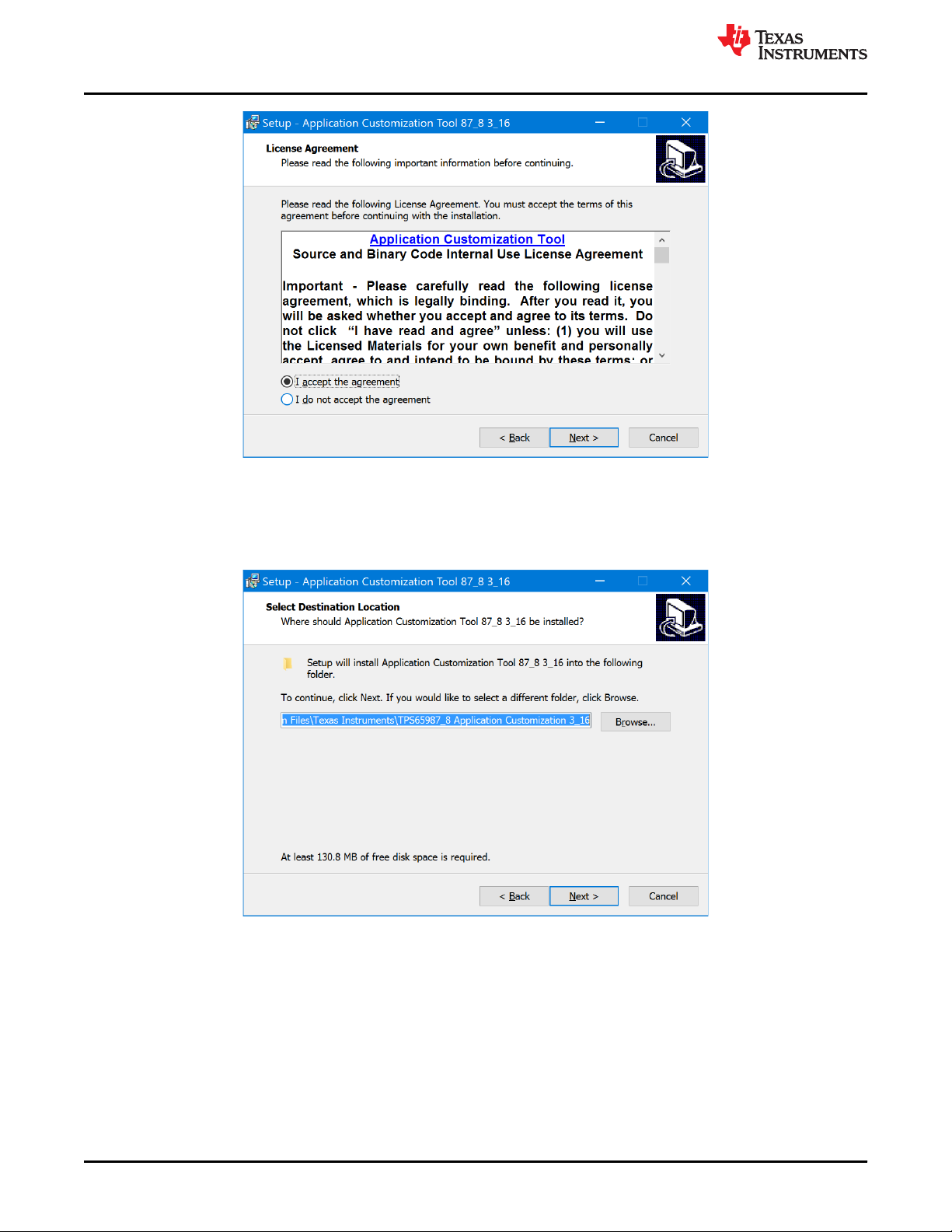
1. Follow the onscreen instructions which are detailed as follows:
a. Read the Source and Binary Code license agreement.
b. If accepted, select the appropriate radio button and then click the Next button.
SLVUB60C – JUNE 2018 – REVISED SEPTEMBER 2020
Submit Document Feedback
TPS659xx Application Customization Tool 3
Copyright © 2020 Texas Instruments Incorporated
Getting Started
Figure 1-1. Installation License Agreement
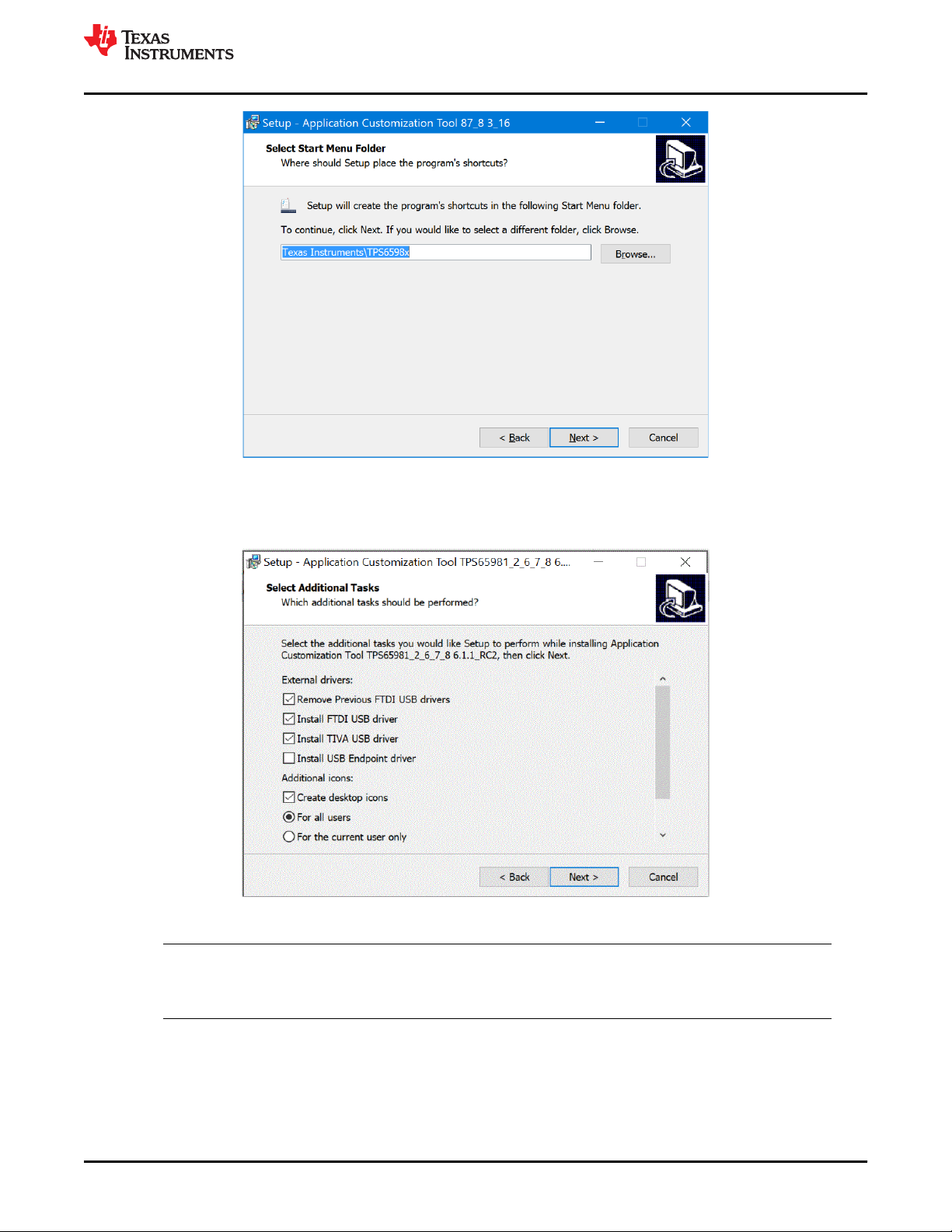
c. Read the Source and Object Code Software license agreement and similarly, if accepted, select the
appropriate radio button and then click the Next button.
d. Use the default location if desired or click Browse to change the location of the installed files. Then click
the Next button.
www.ti.com
Figure 1-2. File Path for Installation Files
e. Again, use the default location, if desired or click Browse to change the location of the installed files. Then
click the Next button.
4 TPS659xx Application Customization Tool SLVUB60C – JUNE 2018 – REVISED SEPTEMBER 2020
Copyright © 2020 Texas Instruments Incorporated
Submit Document Feedback
www.ti.com
Figure 1-3. File Path for Start-Menu Shortcut
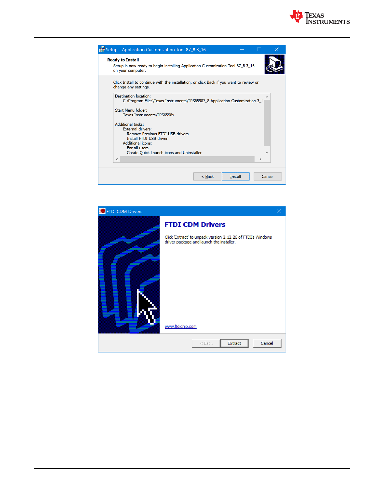
f. Select or deselect the options in Figure 1-4 by checking the corresponding boxes or radio buttons. This
step allows the user to install the desired driver depending on which adapter is used to interface with the
TPS659xx-EVM. TI recommends uninstalling any previous versions of these drivers before installation.
Getting Started
Figure 1-4. Miscellaneous Installation Options
Note
Uninstalling all previous FTDI driver installations will allow the tool to install the FTDI version
2.12.26.
g. Review the selected options and then click Install to start the installation of the tool.
SLVUB60C – JUNE 2018 – REVISED SEPTEMBER 2020
Submit Document Feedback
Copyright © 2020 Texas Instruments Incorporated
TPS659xx Application Customization Tool 5
Getting Started
Figure 1-5. Installation Summary
h. (Optional) If chosen to install FTDI USB driver, click Extract to unpack the FTDI driver.
www.ti.com
Figure 1-6. FTDI Driver Extraction
6 TPS659xx Application Customization Tool SLVUB60C – JUNE 2018 – REVISED SEPTEMBER 2020
Copyright © 2020 Texas Instruments Incorporated
Submit Document Feedback
www.ti.com
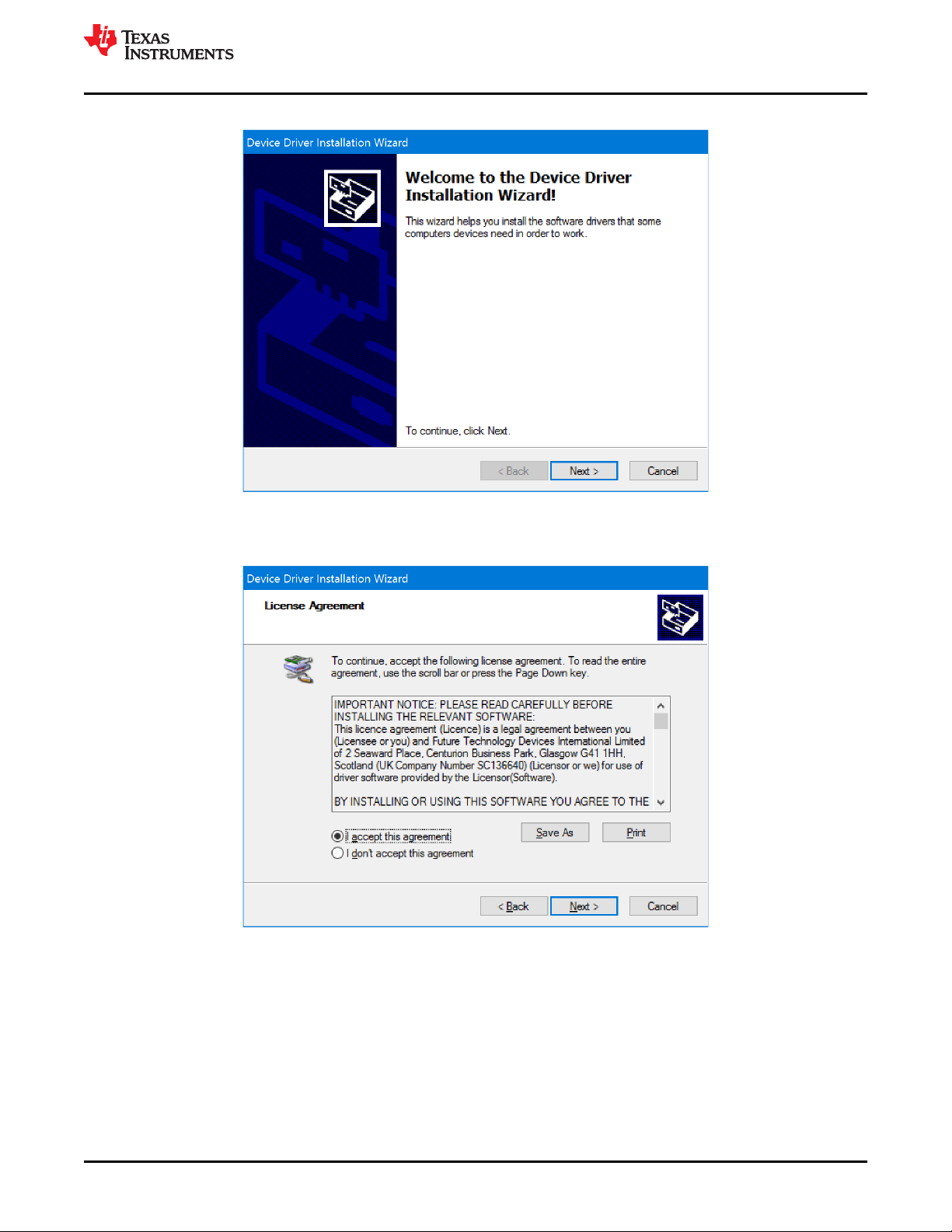
i. (Optional) Click Next to continue with the FTDI Driver installation.
Figure 1-7. FTDI Driver Installation
j. Read the License Agreement for the FTDI Driver.
k. Accept the agreement and select Next > to continue.
Getting Started
Figure 1-8. License Agreement
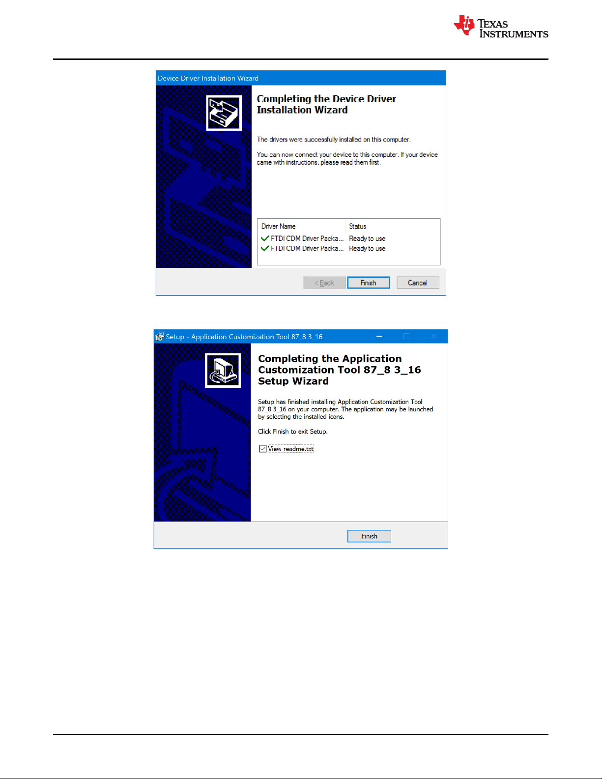
l. When the FTDI driver installation is complete, click the Finish button.
SLVUB60C – JUNE 2018 – REVISED SEPTEMBER 2020
Submit Document Feedback
Copyright © 2020 Texas Instruments Incorporated
TPS659xx Application Customization Tool 7
Getting Started
Figure 1-9. Completed Driver Installation
m. When the tool installation is complete, click the Finish button.
www.ti.com
Figure 1-10. Completed Tool Installation
2. When installed, launch the tool in one of two ways:
• Click the TPS659xx Application Customization shortcut icon on the desktop.
• Use the TPS659xx Application Customization shortcut from the start menu.
8 TPS659xx Application Customization Tool SLVUB60C – JUNE 2018 – REVISED SEPTEMBER 2020
Copyright © 2020 Texas Instruments Incorporated
Submit Document Feedback

www.ti.com
Getting Started
1.5 Features of the TPS659xx Application Customization Tool
The TPS659xx Application Customization Tool provides users with the following capabilities:
1. Generate new configuration settings.
2. Load configuration settings to a device.
3. Read configuration settings from a device.
4. Save configuration settings in JSON format.
5. Debug TPS659xx devices
6. Read/Write configuration registers dynamically.
7. Save configuration register settings to a zip file.
The tool includes TI-provided projects, which are configuration templates that contain settings that are specific to
various applications. These projects are to be used as a starting point in generating configuration images. Users
can select a project that corresponds to the user’s intended device and application.
Note
Projects have a varying level of configurability, depending on the application.
SLVUB60C – JUNE 2018 – REVISED SEPTEMBER 2020
Submit Document Feedback
TPS659xx Application Customization Tool 9
Copyright © 2020 Texas Instruments Incorporated

Using the TPS659xx Application Customization Tool
2 Using the TPS659xx Application Customization Tool
2.1 Default Application Customization Tool Start Page
The start page (Figure 2-1) is displayed after launching the TPS659xx Application Customization Tool.
www.ti.com
Figure 2-1. Start Window of TPS659xx Application Customization Tool
10 TPS659xx Application Customization Tool SLVUB60C – JUNE 2018 – REVISED SEPTEMBER 2020
Copyright © 2020 Texas Instruments Incorporated
Submit Document Feedback

www.ti.com Using the TPS659xx Application Customization Tool
The starting page is a TPS659xx empty template that contains no configuration settings or Firmware Base
Image.
Once you select a “New Project” or “Load Project”, the page updates to show all the menu options which are
listed in Table 2-1
Table 2-1. Features of the configuration tool
Feature Description
Project Select to begin a new project, open an existing project, save the project, export configuration settings as JSON
Binary Select to save the binary or flash from an already saved binary file or current configuration settings
Device Select to import configuration settings from a device
Settings Select to show bitfield ranges, raw field values, or the raw combined configured values
Adapter Select which USB to I2C/SPI adapter (TIVA,FTDI or Aardvark) is used to connect to the TPS659xx EVM
Debug Select to view and edit debug registers and send commands
Documents Select to open application customization tool users guide, application customization tool manifest,
Help Select to open an About window, which describes version information
Change File Allows user to load a new configuration image base image (.bin format). This is primarily applicable when a
Number of Connected
Devices
Port X Settings Click this tab to customize the various configuration settings of an uploaded project. Additional tabs will appear
Firmware Base Image
or import settings from project
configuration image release notes
user has an updated configuration image base image
Allows user to save unique configurations for up to three devices in a single image to flash simultaneously
(through UART)
if more than one device is selected under Device Initialization Chain or if the device has multiple ports
Displays the loaded base binary file that is pre-loaded with the project. This image can be changed by
selecting Change File. Note that no file will be present until a project is selected.
SLVUB60C – JUNE 2018 – REVISED SEPTEMBER 2020
Submit Document Feedback
TPS659xx Application Customization Tool 11
Copyright © 2020 Texas Instruments Incorporated
Using the TPS659xx Application Customization Tool
www.ti.com
2.2 Beginning a New Project
When beginning a new project, new users can open default templates (.tpl) which are provided by Texas
Instruments. The default templates cover primary use cases for all TPS659xx applications. At any time a user
can use the Import Settings from Project feature to help move from one type of template to another as described
in Section 2.4.
Note
The following steps walk through the general process for selecting a default TI template. The
questions asked vary from device to device and may not perfectly match the exact questions shown
below. As an example, the TPS65988DH device is used to walk through the process below. The
devices listed in the application will vary over time based on application updates and as new products
are launched.
To load and use one of the default TI templates, use the following instructions:
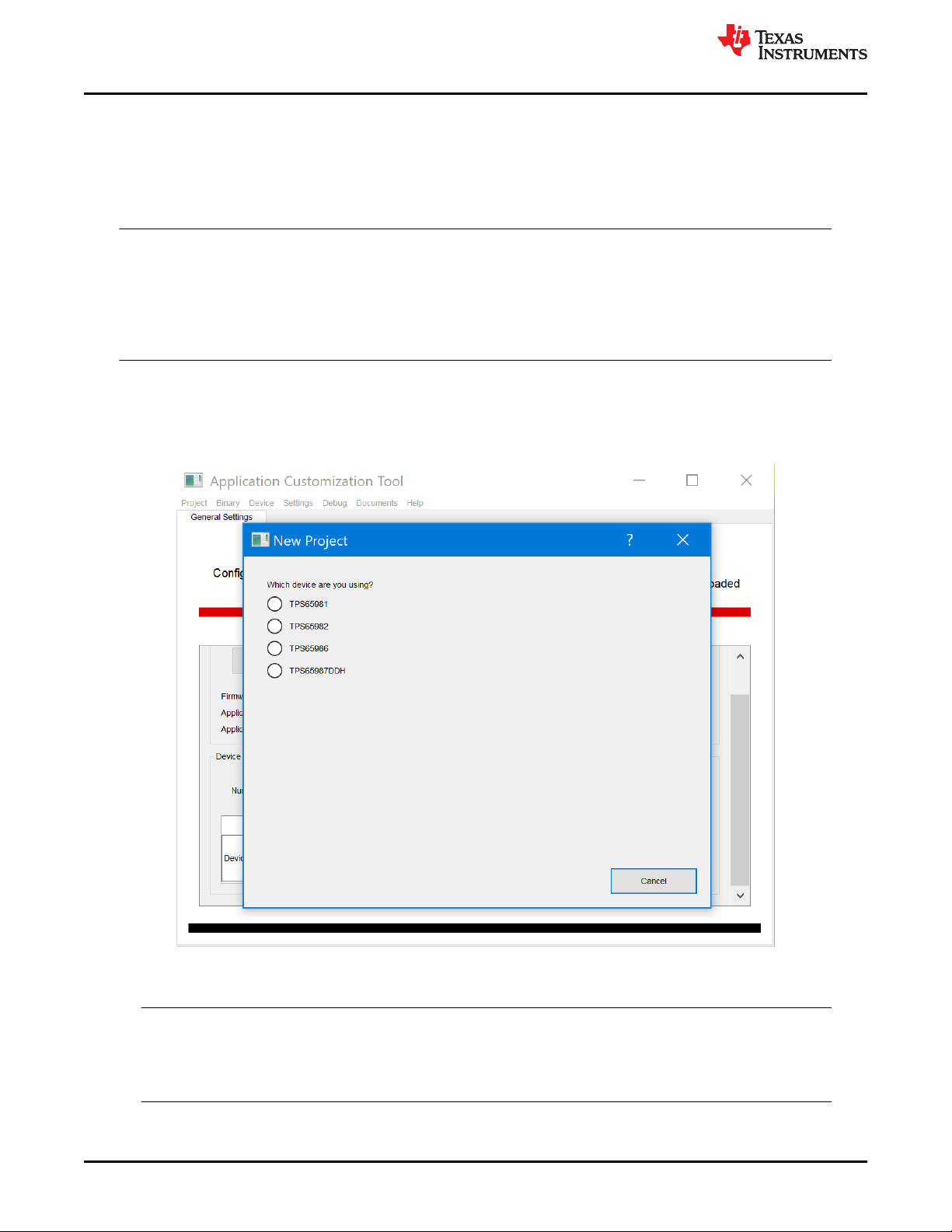
Click the Project tab in the menu. Then select New Project from the drop-down. The pop-up window allows the
user to filter, select, and open a default project.
1. Select the device to be used.
Figure 2-2. Device To Be Used Selection
2. Select the template type to be started with.
Note
Texas Instruments recommends users begin with a “Standard” template. A “Standard” template
preconfigures and hides complex registers while an “Advanced” template will show these registers
and be available for edit.
12 TPS659xx Application Customization Tool SLVUB60C – JUNE 2018 – REVISED SEPTEMBER 2020
Copyright © 2020 Texas Instruments Incorporated
Submit Document Feedback

www.ti.com
3. Select the port type of the design.
Using the TPS659xx Application Customization Tool
Figure 2-3. Template Type Selection
Figure 2-4. Port Type Selection
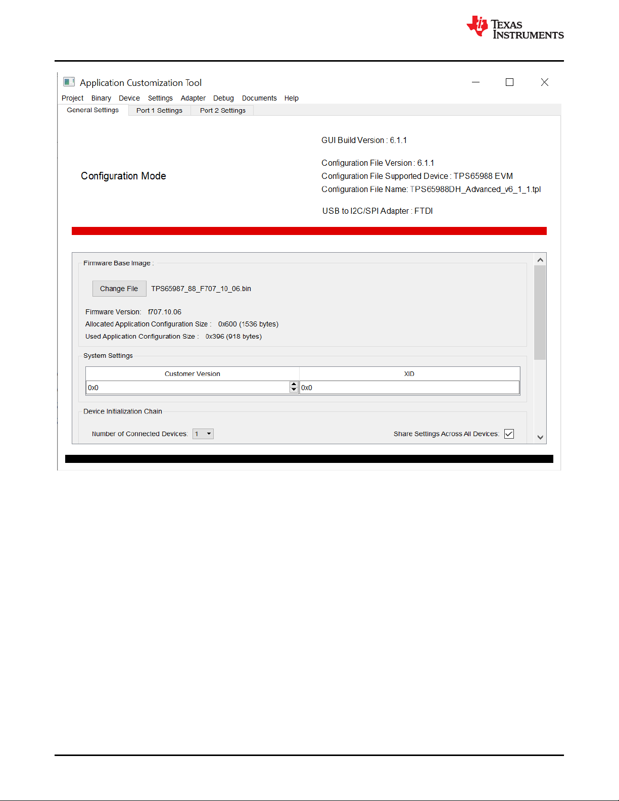
Once selected, the user will be able to see additional functionality. For example, Figure 2-5, the following is
displayed:
• The TPS65988DH_Advanced_v6_1_1.tpl template has been loaded into the tool
• The low-region configuration image binary which corresponds to the template is loaded and shown in the
Firmware Base Image section of the General Settings tab
• The current Adapter as set in the Adapter menu is TIVA
• The available configuration registers are located in the Port X Settings tabs
SLVUB60C – JUNE 2018 – REVISED SEPTEMBER 2020
Submit Document Feedback
Copyright © 2020 Texas Instruments Incorporated
TPS659xx Application Customization Tool 13
Using the TPS659xx Application Customization Tool
www.ti.com
Figure 2-5. TPS659xx Application Customization Tool with Project
4. Under the Device Initialization Chain section of the General Settings tab, select the appropriate number of
devices and bitfield addresses if using a single image to flash more than one TPS659xx device.
5. Click the Port X Settings tabs to configure the settings for the desired application.
6. Once the configuration is complete, select Save Binary under the Binary menu to save the low-region binary
image.
7. Then, select Save Project under the Project menu to save the project settings to the specified location.
The user will now have the low-region binary file (.bin), full-flash binary image (.bin that is directly flashable to the
Flash memory) and a project file (.pjt) and is now ready to flash to the device using the Application
Customization tool.
14 TPS659xx Application Customization Tool SLVUB60C – JUNE 2018 – REVISED SEPTEMBER 2020
Copyright © 2020 Texas Instruments Incorporated
Submit Document Feedback

www.ti.com
Using the TPS659xx Application Customization Tool
2.3 Loading and saving configuration settings as a Project File
As discussed in the previous section, the user can save the configuration settings updates (made in a default TI
template) as a .pjt file format. To make changes to the configuration settings in a project file, first load the project
file, update a new firmware base image (optional), update the configuration settings, and save the project file
using the following steps :
1. Click the Project menu and then select Load Project. The next window displayed allows the user to browse,
select, and open a valid configured project file.
Figure 2-6. Loading a Project
2. Select the configuration file (.pjt). The next window displayed shows the customized configuration settings
and device initialization settings that were selected during creation of this project. The low-region base file
that is included in the original project file is displayed in the Firmware Base Image section of the General
Settings tab.
3. (Optional) Make changes to the number of devices and the selected bitfield addresses in the Device
Initialization Chain section of the General Settings tab.
4. Click the Port x Settings tabs to configure the settings for the desired application.
5. Click the Binary menu and then select Save Binary to save the full-flash binary, low-region binary, or both
binaries.
6. Select Change File to name the binary file and to choose the location.
7. Click the Project menu and then select Save Project to save the project to a specified location.
SLVUB60C – JUNE 2018 – REVISED SEPTEMBER 2020
Submit Document Feedback
Copyright © 2020 Texas Instruments Incorporated
TPS659xx Application Customization Tool 15

Using the TPS659xx Application Customization Tool
www.ti.com
2.4 Importing configuration settings from a Project File
When modifying configurations in different default templates, such as from a Standard to Advanced or vice
versa, the user may find it useful to update a new default template with the same settings. This may be needed
as configurations may be lost when going from different default templates :
1. Click the Project menu and then select Load Project or New Project. The next window displayed allows the
user to browse, select, and open a configuration project file (.pjt) with the desired registers and fields.
2. Once the project file is loaded (wither through Load Project or New Project), click Import Settings from Project
under the Project menu.
3. Select the project file that has the desired settings to be imported
Note
It is not recommended to import settings from a project file of a different device family. In such a
case, the application will disallow the import action
4. Click Open to import the settings for the second project file.
2.5 Loading an updated base firmware image
Firmware base image versions (.bin) are updated more frequently than the configuration tool itself. When it is
necessary to use an updated low-region firmware base image (.bin) instead of the default that is included with
the configuration project, use the following steps to load, modify, and save an updated image to a project.
1. Click the Project menu and then select Load Project or New Project. The next window displayed allows the
user to browse, select, and open a valid configuration project file (.pjt).
2. Once the project file is loaded, click the Change File button to load an updated firmware base image.
Figure 2-7. Changing the Firmware Base Image (Low-Region Binary File)
A new firmware base image is placed in the configuration file. If applicable, the updated firmware base image
information will also be displayed.
16 TPS659xx Application Customization Tool SLVUB60C – JUNE 2018 – REVISED SEPTEMBER 2020
Copyright © 2020 Texas Instruments Incorporated
Submit Document Feedback

www.ti.com
Using the TPS659xx Application Customization Tool
Figure 2-8. Display of an Updated Configuration image Image
3. (Optional) Make any necessary changes to the configuration settings.
4. Save both the binary file and project (including new binary image) using the Save Binary under the Binary
menu, and Save Project under the Project menu.
The new low-region and full-flash images are now available to be flashed onto the TPS659xx device.
2.6 Changing the adapter settings to connect to the device
Click the Adapter menu and then select Configure I2C/SPI Adapter Settings. In the new window, follow the
instructions to specify which adapter is to be used.
1. Specify the appropriate adapter
SLVUB60C – JUNE 2018 – REVISED SEPTEMBER 2020
Submit Document Feedback
TPS659xx Application Customization Tool 17
Copyright © 2020 Texas Instruments Incorporated

Using the TPS659xx Application Customization Tool
www.ti.com
Figure 2-9. USB to I2C/SPI Adapter Configuration Window
2. Enter the I2C Address, if known, to test I2C read, else click Sweep I2C address range for response. When
successful, one or more addresses will pop-up
Figure 2-10. Sample I2C Address Sweep Window
3. Click Test I2C HI Read to try reading back from the Mode Register. This will read back ‘APP’ if the
configuration is correct
4. (Optional) Click Test SPI Read to ensure SPI communication to the device is successful. This option may not
be visible when some projects are selected
5. Click OK when finished configuring
18 TPS659xx Application Customization Tool SLVUB60C – JUNE 2018 – REVISED SEPTEMBER 2020
Copyright © 2020 Texas Instruments Incorporated
Submit Document Feedback

www.ti.com
Using the TPS659xx Application Customization Tool
2.7 Importing Configuration Settings from a TPS659xx
The Application Customization Tool is capable of loading configuration image settings from a TPS659xx at run
time over a USB-to-I2C adapter. This function can be useful if the user wants to take configuration image
settings from a current device and port (or transfer) it over to this tool.
To perform the import function, use the following steps:
1. Load or start a project for the TPS659xx device being used.
2. Click the Device menu and then select Import Settings from Device.
3. Specify the appropriate adapter, I2C address, and Device X, Port X to place the settings.
4. (Optional) Click the Test Read (Mode Register 0x3): button to ensure proper device connection. When read
back, this should read ‘APP’.
Figure 2-11. Import Device Settings Window
5. Click the OK button. If successful, a window is displayed which indicates a successful import of device
settings.
Figure 2-12. Successful Device Settings Import
The configuration settings from the device are now viewable in the Port X Settings tab that was selected. The
full or low-region binary file can now be saved, which can be flashed onto the TPS659xx device using the
Application Customization tool. The modified project (.pjt) file can also be saved, which contains the updated
configuration.
2.8 Exporting project configuration settings as a JSON file
The application allows the user to export the project settings of the device ports, onto a JSON file
1. Click the Project menu and then select Load Project or New Project. The next window displayed allows the
user to browse, select, and open a configuration project file (.pjt) with the desired registers and fields.
SLVUB60C – JUNE 2018 – REVISED SEPTEMBER 2020
Submit Document Feedback
TPS659xx Application Customization Tool 19
Copyright © 2020 Texas Instruments Incorporated

Using the TPS659xx Application Customization Tool
2. Once the project file is loaded and necessary changes are made to the settings, click Export Settings as
JSON under the Project menu. The next window displayed allows the user to browse and select the file
directory where the JSON file will be saved
Figure 2-13. Save Project Data
3. Click OK to export the current project settings
www.ti.com
20 TPS659xx Application Customization Tool SLVUB60C – JUNE 2018 – REVISED SEPTEMBER 2020
Copyright © 2020 Texas Instruments Incorporated
Submit Document Feedback

www.ti.com
Using the TPS659xx Application Customization Tool
2.9 Loading Configuration Image Onto a TPS659xx
The loading configuration image functionality allows the user to automatically create a full-flash image and load it
onto a TPS659xx device over the serial peripheral interface (SPI). After the desired device configuration settings
have been changed within a project file, use the following steps to load the configuration image:
1. Click the Binary menu and then select Flash from current project.
2. Specify the appropriate adapter.
3. (Optional) Click the Read Current Region Offsets button to automatically obtain correct offsets.
Figure 2-14. Load Application Configuration image Window
4. Click OK. At this time, the tool will erase the flash, write the flash, and then verify the flash. If successful, a
window is displayed which indicates a successful SPI Flash.
Figure 2-15. Successful Flash Update
5. Power cycle the TPS659xx device so new configuration image is loaded.
SLVUB60C – JUNE 2018 – REVISED SEPTEMBER 2020
Submit Document Feedback
TPS659xx Application Customization Tool 21
Copyright © 2020 Texas Instruments Incorporated

Using the TPS659xx Application Customization Tool
www.ti.com
2.10 Loading Configuration Image onto a TPS659xx device's RAM
The loading configuration image onto a TPS659xx RAM only functionality allows the user to load a full device
configuration onto the RAM of a TPS659xx device without updating the external non-volatile memory. After the
desired device configuration settings have been changed within a project file, use the following steps to load the
configuration image onto the RAM.
1. Click the Device menu and then select Exporting Settings to Device RAM.
2. Specify the appropriate adapter.
3. (Optional) Click the (Mode Register 0x3): button to ensure proper device connection. When read back, this
should read ‘APP’.
Figure 2-16. Load Application Configuration image to RAM Window
4. Click the OK button. If successful, a window is displayed which indicates a successful import of device
settings.
Figure 2-17. Successful Flash Export
22 TPS659xx Application Customization Tool SLVUB60C – JUNE 2018 – REVISED SEPTEMBER 2020
Copyright © 2020 Texas Instruments Incorporated
Submit Document Feedback

www.ti.com
Using the TPS659xx Application Customization Tool
2.11 Using the Debug Mode
With the Application Customization tool, the user can read and edit from registers during run-time while
connected to the device through the adapter. The user can also take snapshots of all of the registers by entering
the Debug mode with these steps:
1. Load or start a project for the TPS659xx device being used.
2. It is assumed that the adapter has already been selected as mentioned in the previous section
3. Click the Debug menu and then select Debug Mode.
4. Verify that the tool has successfully connected to the device when the connection status in the top right
corner says ‘connected’ and is highlighted in green with the connection method listed IN Figure 2-18.
5. (Optional) To view the bit ranges for each field, select Show Bitfield Ranges under the Settings tab. Similarly,
to view the bit values for each field, select Show Raw Field Values also under the Settings tab.
Figure 2-18. Sample Connection Status and Method in Debug Mode
6. (Optional) To view the bit ranges for each field, select Show Bitfield Ranges under the Settings tab. Similarly,
to view the bit values for each field, select Show Raw Field Values also under the Settings tab.
SLVUB60C – JUNE 2018 – REVISED SEPTEMBER 2020
Submit Document Feedback
TPS659xx Application Customization Tool 23
Copyright © 2020 Texas Instruments Incorporated

Using the TPS659xx Application Customization Tool
www.ti.com
While in Debug Mode, the user is capable of actively writing to registers in the Configuration Registers tab,
reading the current status of registers in Debug Registers, or sending any unique 4CC register commands in the
Commands tab, loading, saving, or executing customized script in the scripting tab.
Figure 2-19. Sample Debug Mode tabs While Connected
When the Polling is shown on the top right side in Figure 2-19, the tool automatically reads data of the currently
displayed register every several seconds. When clicked, Polling changes to Manual, the tool allows user to
manually trigger read, write, or clear operations as introduced in Section 2.11.2,
Figure 2-20. Sample Debug Mode Tabs With Manual Command
The user is also able to take a snapshot of all of the registers, which is highlighted in Section 2.11.3.
Note
To exit Debug Mode and return back to the Application Customization Mode, click on the Debug
Mode, under the Debug menu.
24 TPS659xx Application Customization Tool SLVUB60C – JUNE 2018 – REVISED SEPTEMBER 2020
Copyright © 2020 Texas Instruments Incorporated
Submit Document Feedback

www.ti.com
Using the TPS659xx Application Customization Tool
2.11.1 Reading and Writing Registers Not Shown
With templates like the “Standard” template, some registers are not displayed to the user through the
Configuration Registers, Debug Registers, or Commands tab. In order to read or write to these other registers,
use these following steps:
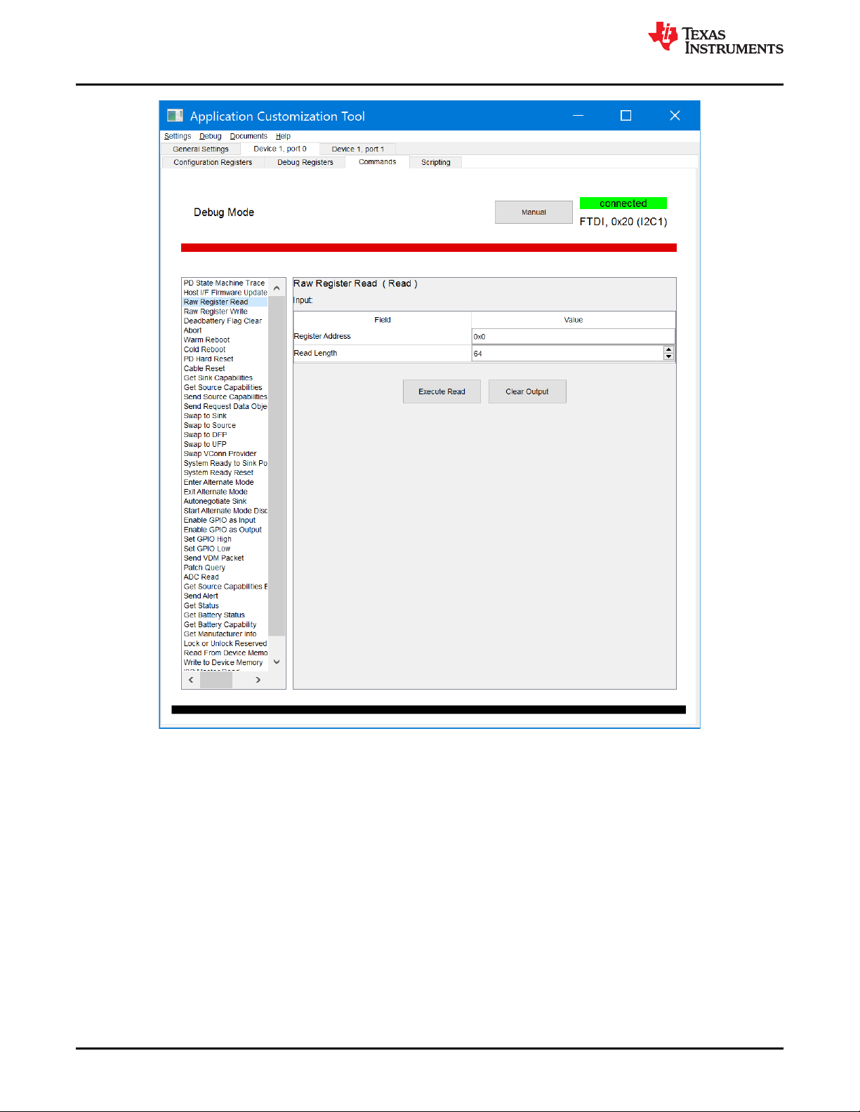
1. In Debug Mode and connected to a running device, enter the Commands tab.
Figure 2-21. Command Tab Window Successfully Entered
2. Select the Raw Register Read to read a register, or Raw Register Write to write to a register.
SLVUB60C – JUNE 2018 – REVISED SEPTEMBER 2020
Submit Document Feedback
Copyright © 2020 Texas Instruments Incorporated
TPS659xx Application Customization Tool 25
Using the TPS659xx Application Customization Tool
www.ti.com
Figure 2-22. Example Raw Register Read Window
3. Enter in the desired register to read or write in hex.
4. (Optional) If writing to the register, enter the desired data in hex.
5. Click Execute Read to return the read register values or Execute Write to write the data to the register. If
successful, the prompt will return Successful Read or Successful Write.
26 TPS659xx Application Customization Tool SLVUB60C – JUNE 2018 – REVISED SEPTEMBER 2020
Copyright © 2020 Texas Instruments Incorporated
Submit Document Feedback

www.ti.com
Using the TPS659xx Application Customization Tool
Figure 2-23. Example of Successful Raw Register Read
6. (Optional) Click Clear Output to read or write another register and repeat at Step 3.
SLVUB60C – JUNE 2018 – REVISED SEPTEMBER 2020
Submit Document Feedback
Copyright © 2020 Texas Instruments Incorporated
TPS659xx Application Customization Tool 27

Using the TPS659xx Application Customization Tool
www.ti.com
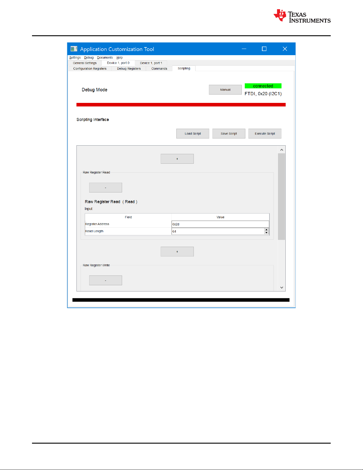
2.11.2 Loading, Saving, and Executing Script Not Shown
In Section 2.11.1, every command is described, if several commands are frequently used together, they can be
configured in the script tab, by using the following steps:
1. In Debug Mode and connected to a running device, enter the script tab.
Figure 2-24. Successfully Entered the Script Tab Window
2. Click “+” in the center of the window, and add a new scripting task.
28 TPS659xx Application Customization Tool SLVUB60C – JUNE 2018 – REVISED SEPTEMBER 2020
Copyright © 2020 Texas Instruments Incorporated
Submit Document Feedback

www.ti.com
Figure 2-25. Example of Adding a New Script Task
3. Click the OK button to add the specific new task.
Using the TPS659xx Application Customization Tool
SLVUB60C – JUNE 2018 – REVISED SEPTEMBER 2020
Submit Document Feedback
TPS659xx Application Customization Tool 29
Copyright © 2020 Texas Instruments Incorporated
Using the TPS659xx Application Customization Tool
www.ti.com
Figure 2-26. Successfully Adding a New Script Task
4. Enter the desired register to read or write in hex.
5. (Optional) If writing to the register, enter the desired data in hex.
6. If more tasks are required, repeat step 2 to step 4, otherwise skip this step.
7. Click Execute Script to execute the added tasks. If successful, a window is displayed which indicates the
executing result.
8. Click Save Script to save the current commands for future use, and click Load Script to load a script that was
saved.
30 TPS659xx Application Customization Tool SLVUB60C – JUNE 2018 – REVISED SEPTEMBER 2020
Copyright © 2020 Texas Instruments Incorporated
Submit Document Feedback

www.ti.com
Using the TPS659xx Application Customization Tool
Figure 2-27. Script Execution Result
SLVUB60C – JUNE 2018 – REVISED SEPTEMBER 2020
Submit Document Feedback
TPS659xx Application Customization Tool 31
Copyright © 2020 Texas Instruments Incorporated

Using the TPS659xx Application Customization Tool
www.ti.com
2.11.3 Taking a Snapshot
A snapshot of the current status of all of the registers can be taken using the following steps:
1. In Debug Mode, click the Debug menu and select Take Snapshot.
2. Select the appropriate location and name to save the snapshot by selecting Change File.
Figure 2-28. Save Snapshot Window
3. Click the OK button.
When the progress bar hits 100%, the tool will save a .zip file at the desire location. The zip file contains text
documents containing all of the Configuration and Debug Register values in words for each port, similar to what
Figure 2-29 shows.
Figure 2-29. Sample Snapshot Text Output
2.12 Miscellaneous Features
When modifying fields, the user may find some ports and registers highlighted in red. This consistency checker
will flag any settings that will not work together.
32 TPS659xx Application Customization Tool SLVUB60C – JUNE 2018 – REVISED SEPTEMBER 2020
Copyright © 2020 Texas Instruments Incorporated
Submit Document Feedback

www.ti.com
Using the TPS659xx Application Customization Tool
In the following example, using the 88 advanced template project, PP2 is originally mapped to VBUS2. When
this is changed to VBUS1, Device 1, Port 1 will light up.
Figure 2-30. Editing the VBUS Mapping
Following the trail of red, the user will see that the PDOs of the Transmit Source Capabilities are red with a
question mark symbol (?) next to the field names. When this symbol is selected, the following window will explain
the inconsistencies. From here, the user may decide how to rectify the problem under the Corrective Actions
section.
SLVUB60C – JUNE 2018 – REVISED SEPTEMBER 2020
Submit Document Feedback
TPS659xx Application Customization Tool 33
Copyright © 2020 Texas Instruments Incorporated

Using the TPS659xx Application Customization Tool
www.ti.com
Figure 2-31. Consistency Check Information Box
The following explains the options under Correction Actions:
• Change Conflict Setting(s) – This will automatically fix the inconsistency displayed below the action as
explained in the warning message
• Ignore – This will ignore the warning message and continue to highlight the field in red.
34 TPS659xx Application Customization Tool SLVUB60C – JUNE 2018 – REVISED SEPTEMBER 2020
Copyright © 2020 Texas Instruments Incorporated
Submit Document Feedback

www.ti.com
Using the Aardvark
®
3 Using the Aardvark
®
3.1 Software and Driver Installation
As discussed in Section 1.3, the Aardvark driver and associated software are not included in the bundled
installer. Use the following steps to install the software and driver:
1. Go to the Total Phase USB Drivers website (https://www.totalphase.com/products/usb-drivers-windows/) to
download the Aardvark driver.
2. Click the USB Drivers – Windows v2.15 to download the software and fill out requested registration
information if an account has not been created.
3. Install the Aardvark drivers using the .exe which is downloaded from the Total Phase website by following
these steps.
a. Extract the .zip file to obtain the TotalPhaseUSB-v2.12.exe file.
b. In Windows 7, right click on the .exe file and select Run as Administrator from the menu.
c. Follow the instructions in the installer window to complete the installation.
4. Go to the Total Phase Aardvark Software site (https://www.totalphase.com/products/aardvark-software-api/)
to download the appropriate Aardvark API Software.
5. Extract the files from the downloaded zip file and search for the python folder. Place aardvark.dll and
aardvark_py.py files into the Configuration Tool Python scripts folder ( C:\Program Files\Texas
Instruments\TPS659xx Application Customization 3.07\tps659xx-app-customizer\gui
\device_if ).
Note
The rest of the files are not required for Aardvark to function.
SLVUB60C – JUNE 2018 – REVISED SEPTEMBER 2020
Submit Document Feedback
TPS659xx Application Customization Tool 35
Copyright © 2020 Texas Instruments Incorporated

Using the Aardvark
®
www.ti.com
3.2 Connecting Aardvark® to TPS659xx-EVM
3.2.1 Direct Connection
The Aardvark connector has an I2C line that must be physically connected to the I2C1 of the TPS659xx device.
Refer to the Aardvark User’s Guide (https://www.totalphase.com/support/articles/200468316) for the pin
connections and descriptions of the Aardvark connector. In this section, this guide will discuss how to connect
the Aardvark to a TPS65988-EVM.
Figure 3-1 is from the design files of the TPS65988-EVM and shows the pin-out of the J3 connector for I2C (pins
15, 17, 19), the J3 connector for SPI (not discussed in the document) and an alternate ground (GND) pin. Figure
3-1 also shows the position of the three I2C lines required on the Total Phase Aardvark adapter: serial clock
(SCL), serial data (SDA), and ground (GND).
Figure 3-1. Texas Instruments TPS65988 Booster Pack J3 and J4 Pin Connections for I2C and SPI
36 TPS659xx Application Customization Tool SLVUB60C – JUNE 2018 – REVISED SEPTEMBER 2020
Copyright © 2020 Texas Instruments Incorporated
Submit Document Feedback

www.ti.com
Using the Aardvark
3.2.2 Aardvark® Using BoosterPack™ to Aardvark® Adapter
The Aardvark can also be connected to the standard 10-pin male header connection on the BoosterPack EVM.
This feature offers the ability to directly connect the Aardvark connector.
Figure 3-2. Aardvark® 10-Pin Header Connection on TPS65988-EVM
®
SLVUB60C – JUNE 2018 – REVISED SEPTEMBER 2020
Submit Document Feedback
TPS659xx Application Customization Tool 37
Copyright © 2020 Texas Instruments Incorporated

IMPORTANT NOTICE AND DISCLAIMER
TI PROVIDES TECHNICAL AND RELIABILITY DATA (INCLUDING DATASHEETS), DESIGN RESOURCES (INCLUDING REFERENCE
DESIGNS), APPLICATION OR OTHER DESIGN ADVICE, WEB TOOLS, SAFETY INFORMATION, AND OTHER RESOURCES “AS IS”
AND WITH ALL FAULTS, AND DISCLAIMS ALL WARRANTIES, EXPRESS AND IMPLIED, INCLUDING WITHOUT LIMITATION ANY
IMPLIED WARRANTIES OF MERCHANTABILITY, FITNESS FOR A PARTICULAR PURPOSE OR NON-INFRINGEMENT OF THIRD
PARTY INTELLECTUAL PROPERTY RIGHTS.
These resources are intended for skilled developers designing with TI products. You are solely responsible for (1) selecting the appropriate
TI products for your application, (2) designing, validating and testing your application, and (3) ensuring your application meets applicable
standards, and any other safety, security, or other requirements. These resources are subject to change without notice. TI grants you
permission to use these resources only for development of an application that uses the TI products described in the resource. Other
reproduction and display of these resources is prohibited. No license is granted to any other TI intellectual property right or to any third
party intellectual property right. TI disclaims responsibility for, and you will fully indemnify TI and its representatives against, any claims,
damages, costs, losses, and liabilities arising out of your use of these resources.
TI’s products are provided subject to TI’s Terms of Sale (www.ti.com/legal/termsofsale.html) or other applicable terms available either on
ti.com or provided in conjunction with such TI products. TI’s provision of these resources does not expand or otherwise alter TI’s applicable
warranties or warranty disclaimers for TI products.
Mailing Address: Texas Instruments, Post Office Box 655303, Dallas, Texas 75265
Copyright © 2020, Texas Instruments Incorporated
 Loading...