

Page 1

User's Guide
SLOU375–July 2013
TPA3132D2EVM Audio Amplifier Evaluation Module
This evaluation module allows users to evaluate the TI's TPA3132D2 audio amplifier. This user's guide
contains an operations description, schematic, printed-circuit board (PCB) layout, and the bill of materials.
Contents
1 Introduction .................................................................................................................. 2
2 Operation ..................................................................................................................... 3
2.1 Quick-Start List for Stand-Alone Operation ..................................................................... 3
3 Schematic, Layout, and Bill of Materials ................................................................................. 4
3.1 TPA3132D2EVM Schematic ...................................................................................... 4
3.2 TPA3132D2EVM Printed-Circuit Board Layers ................................................................ 5
3.3 TPA3132D2EVM Bill of Materials ................................................................................ 6
List of Figures
1 TPA3132D2EVM Audio Power Amplifier – Top View.................................................................. 2
2 TPA3132D2EVM Audio Power Amplifier – Bottom View .............................................................. 2
3 TPA3132D2EVM Schematic............................................................................................... 4
4 TPA3132D2EVM – Top-Side Layout..................................................................................... 5
5 TPA3132D2EVM – Bottom-Side Layout................................................................................. 5
List of Tables
1 Power Supply Requirements .............................................................................................. 3
2 TPA3132D2EVM Jumpers................................................................................................. 3
3 TPA3132D2EVM Bill of Materials......................................................................................... 6
SLOU375–July 2013 TPA3132D2EVM Audio Amplifier Evaluation Module
Submit Documentation Feedback
1
Copyright © 2013, Texas Instruments Incorporated
Page 2
Introduction
1 Introduction
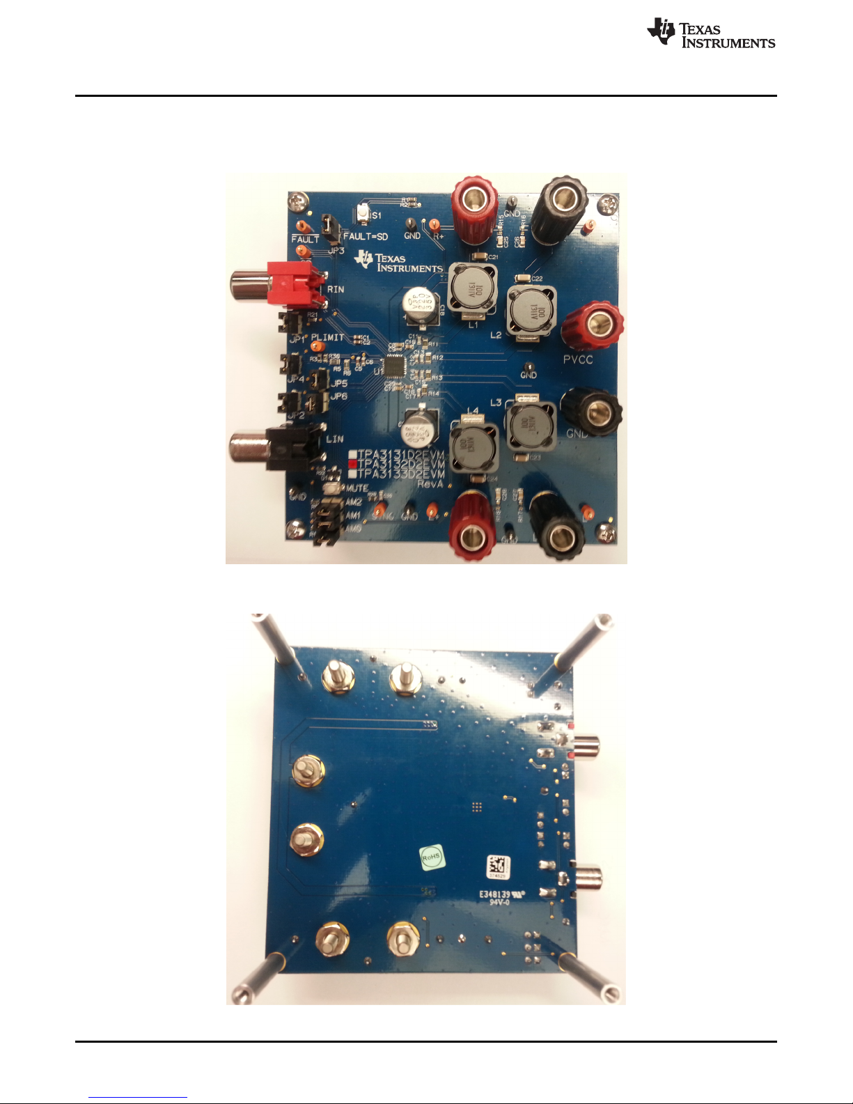
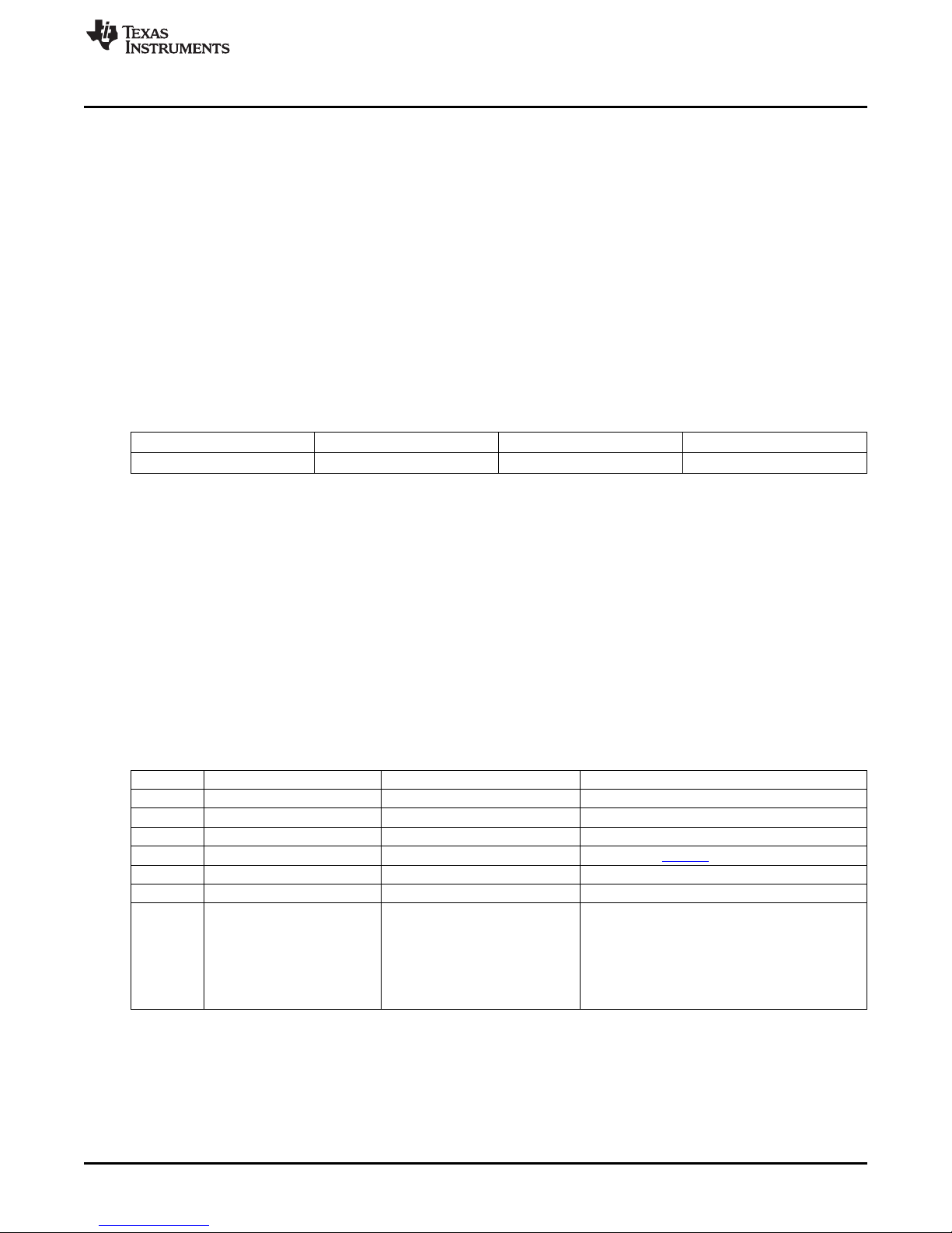
The TPA3132D2EVM (EVM) customer evaluation module, Figure 1 and Figure 2, demonstrates the
TPA3132D2 integrated circuit (IC) from TI.
www.ti.com
Figure 1. TPA3132D2EVM Audio Power Amplifier – Top View
Figure 2. TPA3132D2EVM Audio Power Amplifier – Bottom View
2
TPA3132D2EVM Audio Amplifier Evaluation Module SLOU375–July 2013
Copyright © 2013, Texas Instruments Incorporated
Submit Documentation Feedback
Page 3
www.ti.com
2 Operation
2.1 Quick-Start List for Stand-Alone Operation
Section 2.1.1 and Section 2.1.2 provide instructions for the TPA3132D2EVM in stand-alone operation or
when connecting it into existing circuits or equipment. Connections to the EVM power supply and output
connectors can be made by inserting stripped wire or using banana jacks. The input connectors are RCA
phono jacks.
2.1.1 Power Supply
A single power supply is required to power the EVM. Because most of the pins are PVCC compliant, the
PVCC supply can also be used to power the analog supply (AVcc) and to pull up the logic pins for
shutdown (SD) control, and gain (GAIN). PLIMIT can be powered by an external supply connected to the
PLIMIT pin. Do not power the PLIMIT pin through the PLIMIT network when the PVCC supply is turned
off. This can damage the IC.
Table 1. Power Supply Requirements
Description Voltage Range Current Requirements Wire Size
PVCC 4.5 V to 26 V 3 A 24 AWG
1. Ensure that the external regulated power supply is turned OFF.
2. Connect the external regulated power supply, adjusted from 4.5 V to 26 V, to the PVCC and GND
banana jacks on the EVM taking care to observe marked polarity.
Operation
2.1.2 EVM Preparations
Inputs and Outputs
1. For a BTL configuration, remove jumpers from JP5 and JP6 and connect loads across the outputs
(LEFT+ and LEFT–) and (RIGHT+ and RIGHT–). For PBTL configuration, insert jumpers on JP5 and
JP6 and connect a single load from one of the left speaker jacks to one of the right speaker jacks
2. Connect audio inputs, either differential or single-ended, to the LIN and RIN RCA phono plugs for BTL
operation. For PBTL operation, connect a single input, differential or single-ended, to the RIN RCA
phono plug.
Jumper Function Options Notes
JP1 RCA Gnd to board GND
JP2 RCA Gnd to board GND
JP3 Fault to SD short Auto SD = insert, No SD= open When inserted, fault will pull down SD
JP4 Gvdd to Plimit short Insert to defeat, remove to enable See datasheet (SLOS841)
JP5 BTL or PBTL Insert for PBTL, remove for BTL JP5 and JP6 should match
JP6 BTL or PBTL Insert for PBTL, remove for BTL JP5 and JP6 should match
AM0 Oscillator frequency AM2=0, AM1=0, AM0=0 400 kHz
AM1 AM2=0, AM1=0, AM0=1 500 kHz
AM2 AM2=0, AM1=1, AM0=0 600 kHz
Table 2. TPA3132D2EVM Jumpers
AM2=0, AM1=1, AM0=1 1000 kHz
AM2=1, AM1=0, AM0=0 1200 kHz
AM2=1, AM1=0, AM0=1 Reserved
AM2=1, AM1=1, AM0=0 Reserved
AM2=1, AM1=1, AM0=1 Reserved
Power Up
1. Verify correct power supply voltage and polarity, and turn the external power supply ON. The EVM
begins to operate.
2. Adjust the audio source for the correct volume.
SLOU375–July 2013 TPA3132D2EVM Audio Amplifier Evaluation Module
Submit Documentation Feedback
3
Copyright © 2013, Texas Instruments Incorporated
Page 4

OUTPR
AM2
AM1
AM0
RIN+
RIN- PLIMIT
GAIN/SLV
OUTPL
OUTNL
OUTNR
MUTE
INNR
INPR
INNL
INPL
RIGHT-
RIGHT+
LEFT-
LEFT+
LIN+
LIN-
GND
GND
GND
GND
GND
GND
GND
GND
GND
GND
GND
220ufd/35V
WT
C7
+
0.1ufd/50V
0603 X7R
C8
1000pfd/50V
0402 COG
C9
0.1ufd/50V
0603 X7R
C19
1000pfd/50V
0402 COG
C20
0.22ufd/25V
0603X5R
C10
330pfd/50V
0603 COG
C11
0.22ufd/25V
0603X5R
C12
330pfd/50V
0603 COG
C13
0.22ufd/25V
0603X5R
C14
330pfd/50V
0603 COG
C15
0.22ufd/25V
0603X5R
C16
330pfd/50V
0603 COG
C17
GND
100K/5%
0603
R8
100K/5%
0603
R9
100K/5%
0603
R10
GND
220ufd/35V
WT
C18
+
GND
Black
AM1
JP1
JP2
Orange
SD
Red
PVCC
Black
GND
AM0
AM2
GND
TBD
0603
R3
1.0ufd/16V
0603 X7R
C6
GND
1.0ufd/16V
0603 X7R
C5
GND
Orange
PLIMIT
JP3
Orange
FAULT
JP4
100.0K
08051/8W
R5
08051/8W
20.0K
R6
PVCC
PVCC
PVCC
RCA(Red)
2
3
RIN
1
Shield
C1
0603 X7R
1.0ufd/16V
C2
0603 X7R
1.0ufd/16V
C3
0603 X7R
1.0ufd/16V
C4
0603 X7R
1.0ufd/16V
JP5
JP6
GND
GND
GND
Black
GND GND
GND
Black
Black
GND
R2
0603
100K/5%
S1
GND
47pfd/50V
0603 COG
C30
R20
0603
47K/5%
GND
Orange
SYNC
10/5%
08051/4W
R12
10/5%
08051/4W
R13
10/5%
08051/4W
R14
10/5%
08051/4W
R11
MUTE
40V,1A
SOT23-DBV3
MMBT2222A
Q1
C
E
B
GND
100K/5%
0603
R21
100K/5%
0603
R22
GND
0603
100K/5%
R1
GVDD
PVCC
PVCC
PVCC
PVCC
GND
QFN32-RHB
U1
TPA3131D2RHB
PowerPAD
A
A
3
LDNTPA3131-32-33D2EVM_RevA.SBK
MAY30, 2013
DAVIDK. WILSON
OF
SCH REV
PCB REV
SHEET
DRAWN BY
DATE
FILENAME
PAGEI NFO:
DESIGN LEAD
TI
GND
TPA3133D2RHB
TPA3132D2RHB
QFN32-RHB
TPA3131D2RHB
U1
161514131211109
22
24
20
17
18
19
21
23
29 2628 2732 3031 25
5
8
6
7
3
4
2
1
GND
GND
GND
GND
GND
1206 X7R
0.68ufd/50V
C21
1206 X7R
0.68ufd/50V
C22
1206 X7R
0.68ufd/50V
C23
1206 X7R
0.68ufd/50V
C24
RIGHT+
Red
Orange
R+
RIGHT-
Black
R-
Orange
GND
GND
Black
GND
GND
Black
0805 X7R
0.01ufd/100V
C28
0603
3.3/5%
R18
GND
0.01ufd/100V
0805 X7R
C27
3.3/5%
0603
R17
GND
0805 X7R
0.01ufd/100V
C26
0603
3.3/5%
R16
GND
0.01ufd/100V
0805 X7R
C25
3.3/5%
0603
R15
GND
10uH/5.8A
D128C
1
2
L2
10uH/5.8A
D128C
1
2
L3
LEFT+
Red
LEFT-
Black
L+
Orange
Orange
L-
1
2
D128C
10uH/5.8A
L1
2
1
D128C
10uH/5.8A
L4
LIN
3
2
RCA(Black)
1
Shield
M3x8 M3x8
M3x8
GND
M3x25
GND
M3x25
GND
M3x25
GND
M3x25
M3x8
M3 M3
M3 M3
R30
0603
TBD
STUFF OPTIONS
R30
75K
36K
0.0
BOARD
TPA3131D2
TPA3132D2
TPA3133D2
TPA3131D2RHB/TPA3132D2RHB/TPA3133D2RHB EVALUATION BOARD (RevA)
AM
AVOIDANCE
IN = PBTL
OUT = BTL
ANALOG
INPUTS
POWER
SUPPLY
1TPA3131/3132/3133D2RHBEVALUATIONBOARD
GND
(PBTL+)
(PBTL-)
STUFF
OPTION
TRIPLE FOOTPRINT PADS
D128C - 10uH
DG6045C - 2.2uH
FB1812
ANALOG
OUTPUTS
JUMPER
FOR
PBTL
MODE
JUMPER
FOR
PBTL
MODE
SCREWSWASHERSSTANDOFFS
MOUNTING HARDWARE
L1-L4
10uH DS104C2
10uH D128C
10uH D128C
R3
27K
56K
DNP
Schematic, Layout, and Bill of Materials
www.ti.com
3 Schematic, Layout, and Bill of Materials
3.1 TPA3132D2EVM Schematic
Figure 3 illustrates the schematic for this EVM.
Figure 3. TPA3132D2EVM Schematic
4
TPA3132D2EVM Audio Amplifier Evaluation Module SLOU375–July 2013
Submit Documentation Feedback
Copyright © 2013, Texas Instruments Incorporated
Page 5

www.ti.com
3.2 TPA3132D2EVM Printed-Circuit Board Layers
Figure 4 and Figure 5 illustrate the top- and bottom-side PCB layouts for the EVM.
Schematic, Layout, and Bill of Materials
Figure 4. TPA3132D2EVM – Top-Side Layout
Figure 5. TPA3132D2EVM – Bottom-Side Layout
SLOU375–July 2013 TPA3132D2EVM Audio Amplifier Evaluation Module
Submit Documentation Feedback
5
Copyright © 2013, Texas Instruments Incorporated
Page 6

Schematic, Layout, and Bill of Materials
www.ti.com
3.3 TPA3132D2EVM Bill of Materials
Table 3 is the TPA3132D2EVM BOM.
Table 3. TPA3132D2EVM Bill of Materials
Item MANU PART NUM MANU Qty REF Designators Description
1 TPA3132D2RHB TEXAS INSTRUMENTS 1 U1 100 W FILTER-FREE CLASS D STEREO AMP AM AVOIDANCE QFN32-RHB
ROHS
2 MMBT2222A-7-F DIODES INC. 1 Q1 TRANSISTOR NPN GENERAL PURPOSE 40V 1A SOT23 DBV3 ROHS
3 C1608X7R1C105K TDK 6 C1,C2, C3, C4, C5, C6 CAP SMD0603 CERM 1.0UFD 16V 10% X7R ROHS
4 UWT1V221MNL1GS NICHICON 2 C7, C18 CAP SMD ELECT 220ufd 35V 20% WT ROHS
5 GRM188R71H104KA93D MURATA 2 C8,C19 CAP SMD0603 CERM 0.1UFD 50V 10% X7R ROHS
6 GRM1555C1H102JA01D MURATA 2 C9,C20 CAP SMD0402 CERM 1000pfd 5% 50V COG ROHS
7 06033D224KAT2A AVX 4 C10, C12, C14, C16 CAPSMD0603 CERM 0.22UFD 25V 10% X5R ROHS
8 GRM1885C1H331JA01D MURATA 4 C11,C13, C15, C17 CAP SMD0603 CERM 330PFD 50V 5% COG ROHS
9 C1206C684K5RACTU KEMET 4 C21,C22, C23, C24 CAP SMD1206 CERM 0.68UFD 50V 10% X7R ROHS
10 GRM21BR72A103KA01L MURATA 4 C25, C26, C27, C28 CAP SMD0805 CERM 0.01UFD 100V 10% X7R ROHS
11 GRM1885C1H470JA01D MURATA 1 C30 CAP SMD0603 CERM 47PFD 50V 5% COG ROHS
12 RMCF0603JT100K STACKPOLE ELECTRONICS 7 R1, R2, R8, R9, R10, RESISTOR SMD0603 100K OHMS 5% 1/10W ROHS
R21, R22
13 ERJ-3EKF5602V PANASONIC 1 R3 RESISTOR SMD0603 56.0K OHM 1% THICK FILM 1/10W ROHS
14 MCR10EZHF1003 ROHM 1 R5 RESISTOR SMD0805 100.0 KOHMs 1% 1/8W ROHS
15 MCR10EZHF2002 ROHM 1 R6 RESISTOR SMD0805 20.0 KOHMs 1% 1/8W ROHS
16 ESR10EZPJ100 ROHM 4 R11, R12, R13, R14 RESISTOR SMD0805 10 OHM 5% 1/4W ROHS
17 ERJ-3GEYJ3R3V PANASONIC 4 R15, R16, R17, R18 RESISTOR SMD0603 3.3 OHMS 5% 1/10W ROHS
18 ERJ-3GEYJ473V PANASONIC 1 R20 RESISTOR SMD0603 47K OHMS 5% 1/10W ROHS
19 RC0603FR-0736KL YAGEO 1 R30 RESISTOR SMD0603 THICK FILM 36.0K OHMS 1% 1/10W ROHS
20 931BS-100M TOKO 4 L1,L2, L3, L4 INDUCTOR 10uH 5.8A TYPE D128C ROHS
21 PBC02SAAN SULLINS 9 AM0, AM1, AM2, JP1, HEADERTHRU MALE 2 PIN 100LS GOLD ROHS
JP2, JP3, JP4, JP5, JP6
22 PJRAN1X1U013 SWITCHCRAFT 1 RIN JACK, RCA 3-PIN PCB-RA RED ROHS
23 PJRAN1X1U01X SWITCHCRAFT 1 LIN JACK, RCA 3-PIN PCB-RA BLACK ROHS
24 5001 KEYSTONE ELECTRONICS 6 G1, G2, G3, G4, G5, G6 PC TESTPOINT, BLACK, ROHS
25 5003 KEYSTONE ELECTRONICS 8 L+, L-, R+, R-, SD, PC TESTPOINT, ORANGE, ROHS
SYNC, FAULT, PLIMIT
26 TL1015AF160QG E-SWITCH 2 S1, MUTE SWITCH, MOM, 160G SMT 4X3MM ROHS
27 7006 KEYSTONE ELECTRONICS 3 PVCC, LEFT+, RIGHT+ BINDING POST, RED, 15A ECONO ROHS
28 7007 KEYSTONE ELECTRONICS 3 GND, LEFT-, RIGHT- BINDING POST, BLACK, 15A ECONO ROHS
6
TPA3132D2EVM Audio Amplifier Evaluation Module SLOU375–July 2013
Submit Documentation Feedback
Copyright © 2013, Texas Instruments Incorporated
Page 7

www.ti.com
Schematic, Layout, and Bill of Materials
Table 3. TPA3132D2EVM Bill of Materials (continued)
Item MANU PART NUM MANU Qty REF Designators Description
29 95947A018 MCMASTER-CARR 4 STANDOFFS STANDOFF M3x25mm 4.5mm DIA HEX ALUM F-F ROHS
30 92148A150 MCMASTER-CARR 4 STANDOFFWASHERS WASHER SPLIT-LOCK M3 6.2mm OD 0.7mm THICK STAINLESS STEEL ROHS
31 92000A118 MCMASTER-CARR 4 STANDOFFSCREWS SCREW M3x8 PHILIPS PANHEAD STAINLESS STEEL ROHS
32 969102-0000-DA 3M 9 AM0, AM1, AM2, JP1, SHUNT BLACK AU FLASH 0.100LS OPEN TOP ROHS
JP2, JP3, JP4, JP5, JP6
TOTAL 109
SPECIAL NOTES TO THIS BILL OF MATERIALS
SN1 These assemblies are ESD sensitive, ESD precautions shall be observed.
SN2 These assemblies must be clean and free from flux and all contaminants. Use of no clean flux is not acceptable.
SN3 These assemblies must comply with workmanship standards IPC-A-610 Class 2.
SN4 Ref designators marked with an asterisk ('**') cannot be substituted. All other components can be substituted with equivalent MFG's components.
7
SLOU375–July 2013 TPA3132D2EVM Audio Amplifier Evaluation Module
Submit Documentation Feedback
Copyright © 2013, Texas Instruments Incorporated
Page 8

IMPORTANT NOTICE
Texas Instruments Incorporated and its subsidiaries (TI) reserve the right to make corrections, enhancements, improvements and other
changes to its semiconductor products and services per JESD46, latest issue, and to discontinue any product or service per JESD48, latest
issue. Buyers should obtain the latest relevant information before placing orders and should verify that such information is current and
complete. All semiconductor products (also referred to herein as “components”) are sold subject to TI’s terms and conditions of sale
supplied at the time of order acknowledgment.
TI warrants performance of its components to the specifications applicable at the time of sale, in accordance with the warranty in TI’s terms
and conditions of sale of semiconductor products. Testing and other quality control techniques are used to the extent TI deems necessary
to support this warranty. Except where mandated by applicable law, testing of all parameters of each component is not necessarily
performed.
TI assumes no liability for applications assistance or the design of Buyers’ products. Buyers are responsible for their products and
applications using TI components. To minimize the risks associated with Buyers’ products and applications, Buyers should provide
adequate design and operating safeguards.
TI does not warrant or represent that any license, either express or implied, is granted under any patent right, copyright, mask work right, or
other intellectual property right relating to any combination, machine, or process in which TI components or services are used. Information
published by TI regarding third-party products or services does not constitute a license to use such products or services or a warranty or
endorsement thereof. Use of such information may require a license from a third party under the patents or other intellectual property of the
third party, or a license from TI under the patents or other intellectual property of TI.
Reproduction of significant portions of TI information in TI data books or data sheets is permissible only if reproduction is without alteration
and is accompanied by all associated warranties, conditions, limitations, and notices. TI is not responsible or liable for such altered
documentation. Information of third parties may be subject to additional restrictions.
Resale of TI components or services with statements different from or beyond the parameters stated by TI for that component or service
voids all express and any implied warranties for the associated TI component or service and is an unfair and deceptive business practice.
TI is not responsible or liable for any such statements.
Buyer acknowledges and agrees that it is solely responsible for compliance with all legal, regulatory and safety-related requirements
concerning its products, and any use of TI components in its applications, notwithstanding any applications-related information or support
that may be provided by TI. Buyer represents and agrees that it has all the necessary expertise to create and implement safeguards which
anticipate dangerous consequences of failures, monitor failures and their consequences, lessen the likelihood of failures that might cause
harm and take appropriate remedial actions. Buyer will fully indemnify TI and its representatives against any damages arising out of the use
of any TI components in safety-critical applications.
In some cases, TI components may be promoted specifically to facilitate safety-related applications. With such components, TI’s goal is to
help enable customers to design and create their own end-product solutions that meet applicable functional safety standards and
requirements. Nonetheless, such components are subject to these terms.
No TI components are authorized for use in FDA Class III (or similar life-critical medical equipment) unless authorized officers of the parties
have executed a special agreement specifically governing such use.
Only those TI components which TI has specifically designated as military grade or “enhanced plastic” are designed and intended for use in
military/aerospace applications or environments. Buyer acknowledges and agrees that any military or aerospace use of TI components
which have not been so designated is solely at the Buyer's risk, and that Buyer is solely responsible for compliance with all legal and
regulatory requirements in connection with such use.
TI has specifically designated certain components as meeting ISO/TS16949 requirements, mainly for automotive use. In any case of use of
non-designated products, TI will not be responsible for any failure to meet ISO/TS16949.
Products Applications
Audio www.ti.com/audio Automotive and Transportation www.ti.com/automotive
Amplifiers amplifier.ti.com Communications and Telecom www.ti.com/communications
Data Converters dataconverter.ti.com Computers and Peripherals www.ti.com/computers
DLP® Products www.dlp.com Consumer Electronics www.ti.com/consumer-apps
DSP dsp.ti.com Energy and Lighting www.ti.com/energy
Clocks and Timers www.ti.com/clocks Industrial www.ti.com/industrial
Interface interface.ti.com Medical www.ti.com/medical
Logic logic.ti.com Security www.ti.com/security
Power Mgmt power.ti.com Space, Avionics and Defense www.ti.com/space-avionics-defense
Microcontrollers microcontroller.ti.com Video and Imaging www.ti.com/video
RFID www.ti-rfid.com
OMAP Applications Processors www.ti.com/omap TI E2E Community e2e.ti.com
Wireless Connectivity www.ti.com/wirelessconnectivity
Mailing Address: Texas Instruments, Post Office Box 655303, Dallas, Texas 75265
Copyright © 2013, Texas Instruments Incorporated
 Loading...