

Page 1
QFN
HTQFP
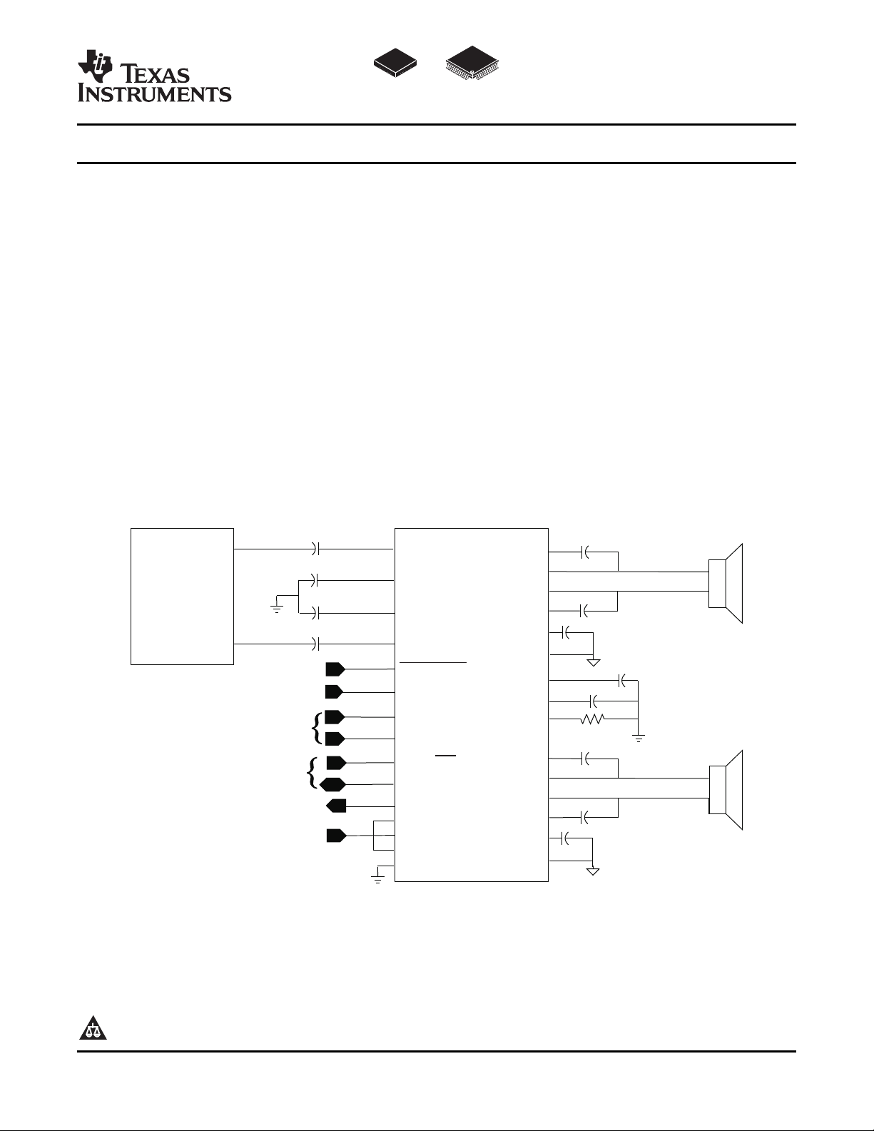
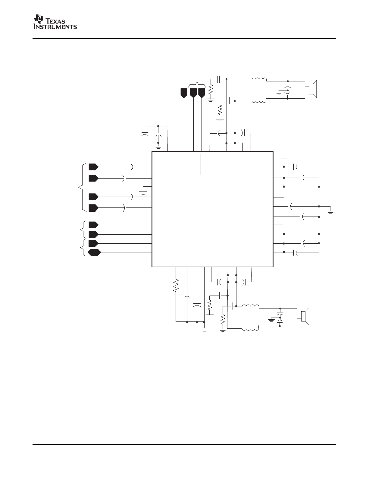
Simplified ApplicationCircuit
TV Audio
Processor
RINP
BSRN
BSRP
VCLAMPR
VCLAMPL
PGNDR
PGNDL
VREG
VBYP
ROSC
BSLN
ROUTN
LOUTN
LOUTP
BSLP
ROUTP
TPA3101D2
LINN
RINN
LINP
MUTE
GAIN0
GAIN1
SYNC
FAULT
PVCCR
PVCCL
AVCC
AGND
MSTR/SLV
SHUTDOWN
Shutdown
Control
MuteControl
SyncControl
FaultFlag
10Vto26V
GainSelect
1 Fm
1 Fm
1 Fm
1 Fm
10nF
100kW
0.22 Fm
0.22 Fm
0.22 Fm
0.22 Fm
1 Fm
1 Fm
1 Fm
TPA3101D2
www.ti.com
SLOS473B – DECEMBER 2005 – REVISED SEPTEMBER 2007
10-W STEREO CLASS-D AUDIO POWER AMPLIFIER
1
FEATURES APPLICATIONS
• 10-W/ch into an 8- Ω Load From a 13-V Supply
• 9.2-W/ch into an 8- Ω Load From a 12-V Supply
• Operates from 10 V to 26 V
• 87% Efficient Class-D Operation Eliminates
Need for Heat Sinks
• Four Selectable, Fixed Gain Settings
• Differential Inputs TPA3101D2, 87%, eliminates the need for an
• Thermal and Short-Circuit Protection With
Auto Recovery Feature
• Clock Output for Synchronization With
Multiple Class-D Devices
• Surface Mount 7 mm × 7 mm, 48-pin QFN
Package
• Surface Mount 7 mm × 7 mm, 48-pin HTQFP
Package
• Televisions
DESCRIPTION
The TPA3101D2 is a 10-W (per channel) efficient,
Class-D audio power amplifier for driving bridged-tied
stereo speakers. The TPA3101D2 can drive stereo
speakers as low as 4 Ω . The high efficiency of the
external heat sink when playing music.
The gain of the amplifier is controlled by two gain
select pins. The gain selections are 20, 26, 32,
36 dB.
The outputs are fully protected against shorts to
GND, V
recovery feature and monitor output.
, and output-to-output shorts with an auto
CC
1
Please be aware that an important notice concerning availability, standard warranty, and use in critical applications of Texas Instruments semiconductor products and disclaimers thereto appears at the end of this data sheet.
PRODUCTION DATA information is current as of publication date.
Products conform to specifications per the terms of the Texas
Instruments standard warranty. Production processing does not
necessarily include testing of all parameters.
Copyright © 2005 – 2007, Texas Instruments Incorporated
Page 2
www.ti.com
TPA3101D2
SLOS473B – DECEMBER 2005 – REVISED SEPTEMBER 2007
These devices have limited built-in ESD protection. The leads should be shorted together or the device placed in conductive foam
during storage or handling to prevent electrostatic damage to the MOS gates.
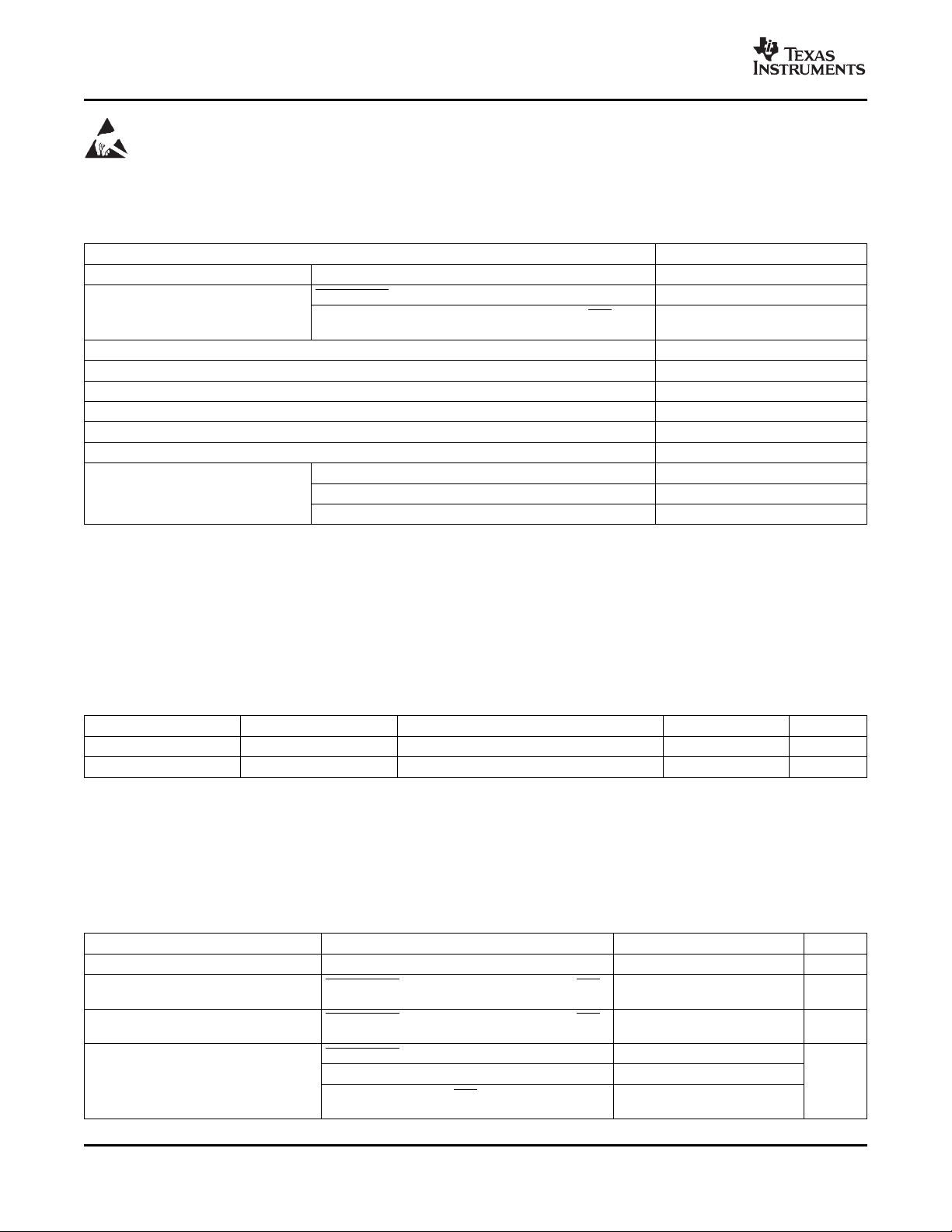
ABSOLUTE MAXIMUM RATINGS
over operating free-air temperature range (unless otherwise noted)
V
V
T
T
T
R
(1) Stresses beyond those listed under absolute maximum ratings may cause permanent damage to the device. These are stress ratings
(2) The TPA3101D2 incorporates an exposed thermal pad on the underside of the chip. This acts as a heatsink, and it must be connected
(3) In accordance with JEDEC Standard 22, Test Method A114-B.
(4) In accordance with JEDEC Standard 22, Test Method A115-A
(5) In accordance with JEDEC Standard 22, Test Method C101-A
Supply voltage AVCC, PVCC – 0.3 V to 30 V
CC
SHUTDOWN, MUTE – 0.3 V to V
Input voltage
I
GAIN0, GAIN1, RINN, RINP, LINN, LINP, MSTR/ SLV,
SYNC
Continuous total power dissipation See Dissipation Rating Table
Operating free-air temperature range – 40 ° C to 85 ° C
A
Operating junction temperature range
J
Storage temperature range – 65 ° C to 150 ° C
stg
(2)
Lead temperature 1,6 mm (1/16 inch) from case for 10 seconds 260 ° C
Load Resistance 3.2 Ω Minimum
(Load)
Human body model
Electrostatic discharge Machine model
Charged-device model
(3)
(all pins) ± 2 kV
(4)
(all pins) ± 200 V
(5)
only, and functional operations of the device at these or any other conditions beyond those indicated under recommended operating
conditions is not implied. Exposure to absolute-maximum-rated conditions for extended periods may affect device reliability.
to a thermally dissipating plane for proper power dissipation. Failure to do so may result in the device going into thermal protection
shutdown. See TI Technical Briefs SCBA017D and SLUA271 for more information about using the QFN thermal pad. See TI Technical
Briefs SLMA002 for more information about using the HTQFP thermal pad.
(1)
UNIT
– 0.3 V to VREG + 0.5 V
– 40 ° C to 150 ° C
(all pins) ± 500 V
+ 0.3 V
CC
TYPICAL DISSIPATION RATINGS
PACKAGE TA≤ 25 ° C DERATING FACTOR TA= 70 ° C TA= 85 ° C
48-pin RGZ (QFN) 4.39 W 35.1 mW/ ° C
48-pin PHP (HTQFP) 4.82 W 38.6 mW/ ° C
(1)
(2)
2.81 W 2.28 W
3.09 W 2.51 W
(1) This data was taken using 1 oz trace and copper pad that is soldered directly to a JEDEC standard high-k PCB. The thermal pad must
be soldered to a thermal land on the printed-circuit board. See TI Technical Briefs SCBA017D and SLUA271 for more information about
using the QFN thermal pad.
(2) This data was taken using 1 oz trace and copper pad that is soldered directly to a JEDEC standard high-k PCB. The thermal pad must
be soldered to a thermal land on the printed-circuit board. See TI Technical Briefs SLMA002 for more information about using the
HTQFP thermal pad.
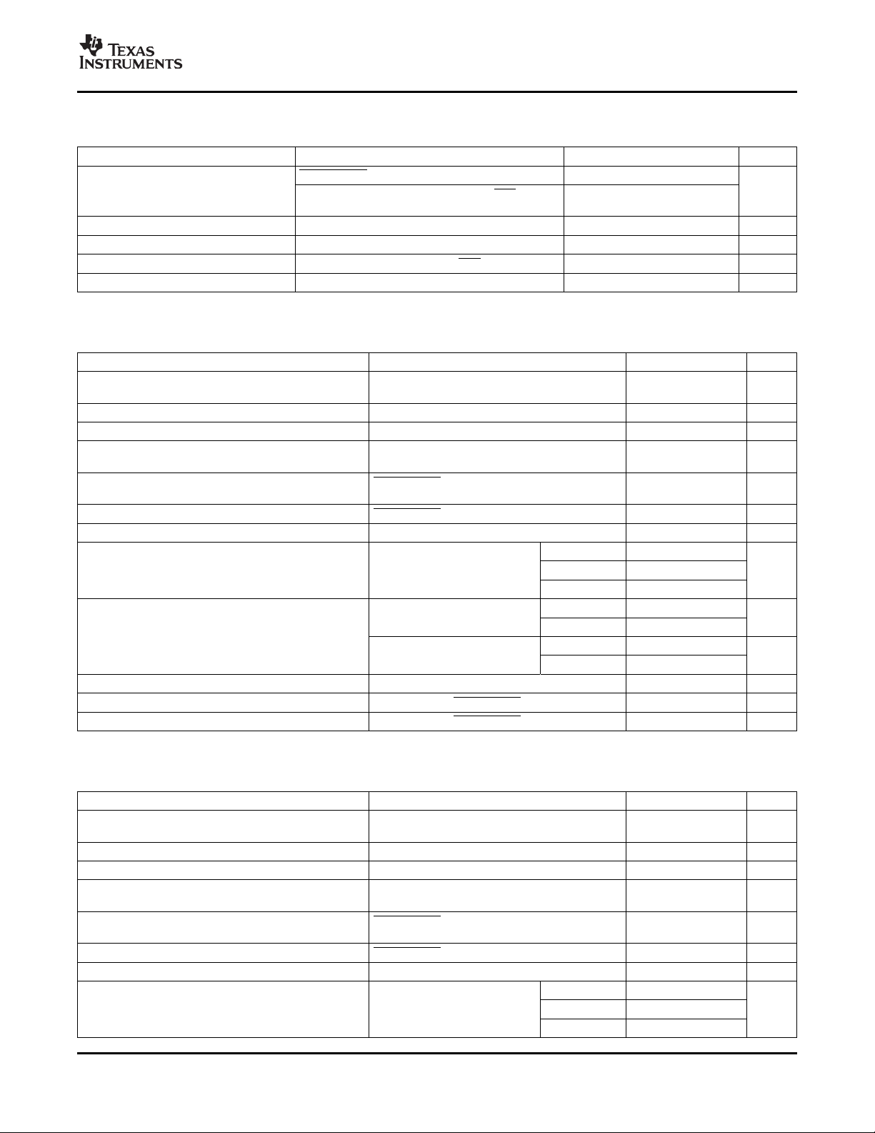
RECOMMENDED OPERATING CONDITIONS
over operating free-air temperature range (unless otherwise noted)
PARAMETER TEST CONDITIONS MIN MAX UNIT
V
V
V
I
Supply voltage PVCC, AVCC 10 26 V
CC
High-level input voltage 2 V
IH
Low-level input voltage 0.8 V
IL
High-level input current µA
IH
SHUTDOWN, MUTE, GAIN0, GAIN1, MSTR/ SLV,
SYNC
SHUTDOWN, MUTE, GAIN0, GAIN1, MSTR/ SLV,
SYNC
SHUTDOWN, VI= VCC, V
MUTE, VI= VCC, V
CC
= 24 V 125
CC
= 24 V 75
GAIN0, GAIN1, MSTR/ SLV, SYNC, VI= VREG,
V
= 24 V
CC
2
2 Submit Documentation Feedback Copyright © 2005 – 2007, Texas Instruments Incorporated
Product Folder Link(s): TPA3101D2
Page 3
www.ti.com
TPA3101D2
SLOS473B – DECEMBER 2005 – REVISED SEPTEMBER 2007
RECOMMENDED OPERATING CONDITIONS (continued)
over operating free-air temperature range (unless otherwise noted)
PARAMETER TEST CONDITIONS MIN MAX UNIT
SHUTDOWN, VI= 0, V
I
V
V
f
T
Low-level input current µA
IL
High-level output voltage FAULT, IOH= 1 mA VREG - 0.6 V
OH
Low-level output voltage FAULT, IOL= -1 mA AGND + 0.4 V
OL
Oscillator frequency R
OSC
Operating free-air temperature – 40 85 ° C
A
SYNC, MUTE, GAIN0, GAIN1, MSTR/ SLV, VI= 0 1
V, V
= 24 V
CC
Resistor = 100 k Ω , MSTR/ SLV = 2 V 200 300 kHz
osc
DC CHARACTERISTICS
TA= 25 ° C, V
| V
| VI= 0 V, Gain = 36 dB 5 50 mV
OS
PSRR DC Power supply rejection ratio -70 dB
I
CC
I
CC(SD)
I
CC(MUTE)
r
DS(on)
G Gain
t
ON
t
OFF
= 24 V, RL= 8 Ω (unless otherwise noted)
CC
PARAMETER TEST CONDITIONS MIN TYP MAX UNIT
Class-D output offset voltage (measured
differentially)
Bypass reference for input amplifier VBYP, no load 1.1 1.25 1.45 V
4-V internal supply voltage VREG, no load, V
V
CC
Gain = 36 dB
Quiescent supply current SHUTDOWN = 2 V, MUTE = 0 V, no load, filter 22 26.5 mA
or snubber
Quiescent supply current in shutdown mode SHUTDOWN = 0.8 V, no load, filter or snubber 300 400 µA
Quiescent supply current in mute mode MUTE = 2 V, no load, filter or snubber 8 10 mA
V
Drain-source on-state resistance Low side 370 m Ω
CC
TJ= 25 ° C
GAIN1 = 0.8 V dB
GAIN1 = 2 V dB
Gain matching Between channels 2%
Turn-on time C
Turn-off time C
(VBYP)
(VBYP)
= 24 V 2
CC
= 10 V to 26 V 3.75 4 4.25 V
CC
= 12 V to 24 V, inputs ac coupled to AGND,
High Side 370
= 12 V, IO= 500 mA,
Total 780 950
GAIN0 = 0.8 V 19 20 21
GAIN0 = 2 V 25 26 27
GAIN0 = 0.8 V 31 32 33
GAIN0 = 2 V 35 36 37
= 1 µF, SHUTDOWN = 2 V 25 ms
= 1 µF, SHUTDOWN = 0.8 V 0.1 ms
DC CHARACTERISTICS
TA= 25 ° C, V
| V
| VI= 0 V, Gain = 36 dB 5 50 mV
OS
PSRR DC Power supply rejection ratio -70 dB
I
CC
I
CC(SD)
I
CC(MUTE)
r
DS(on)
Copyright © 2005 – 2007, Texas Instruments Incorporated Submit Documentation Feedback 3
= 12 V, RL= 8 Ω (unless otherwise noted)
CC
PARAMETER TEST CONDITIONS MIN TYP MAX UNIT
Class-D output offset voltage (measured
differentially)
Bypass reference for input amplifier VBYP, no load 1.1 1.25 1.45 V
4-V internal supply voltage VREG, no load 3.75 4 4.25 V
V
= 12 V to 24 V, Inputs ac coupled to AGND,
CC
Gain = 36 dB
Quiescent supply current SHUTDOWN = 2 V, MUTE = 0 V, no load, filter 18 22.5 mA
or snubber
Quiescent supply current in shutdown mode SHUTDOWN = 0.8 V, no load, filter or snubber 180 300 µA
Quiescent supply current in mute mode MUTE = 2 V, no load, filter or snubber 7 9 mA
High Side 370
V
= 12 V, IO= 500 mA,
Drain-source on-state resistance Low side 370 m Ω
CC
TJ= 25 ° C
Total 780 950
Product Folder Link(s): TPA3101D2
Page 4
www.ti.com
TPA3101D2
SLOS473B – DECEMBER 2005 – REVISED SEPTEMBER 2007
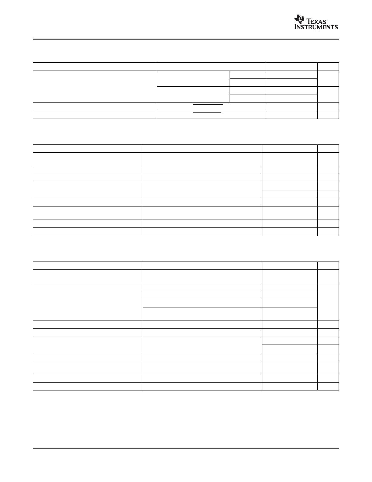
DC CHARACTERISTICS (continued)
TA= 25 ° C, V
G Gain
t
ON
t
OFF
AC CHARACTERISTICS
TA= 25 ° C, V
K
SVR
P
O
THD+N Total harmonic distortion + noise f = 1 kHz, PO= 5 W (half-power) 0.09%
V
n
SNR Signal-to-noise ratio 102 dB
= 12 V, RL= 8 Ω (unless otherwise noted)
CC
PARAMETER TEST CONDITIONS MIN TYP MAX UNIT
GAIN0 = 0.8 V 19 20 21
GAIN0 = 2 V 25 26 27
GAIN0 = 0.8 V 31 32 33
GAIN0 = 2 V 35 36 37
Turn-on time C
Turn-off time C
= 24 V, RL= 8 Ω (unless otherwise noted)
CC
GAIN1 = 0.8 V dB
GAIN1 = 2 V dB
= 1 µF, SHUTDOWN = 2 V 25 ms
(VBYP)
= 1 µF, SHUTDOWN = 0.8 V 0.1 ms
(VBYP)
PARAMETER TEST CONDITIONS MIN TYP MAX UNIT
Supply ripple rejection – 70 dB
200 mV
Gain = 20 dB, Inputs ac-coupled to AGND
ripple from 20 Hz – 1 kHz,
PP
Continuous output power THD+N = 0.09%, f = 1 kHz (thermally limited) 10 W
Output integrated noise 20 Hz to 22 kHz, A-weighted filter, Gain = 20 dB
100 µV
– 80 dBV
Crosstalk VO= 1 Vrms, Gain = 20 dB, f = 1 kHz – 92 dB
Maximum output at THD+N < 1%, f = 1 kHz,
Gain = 20 dB, A-weighted
Thermal trip point 150 ° C
Thermal hysteresis 30 ° C
AC CHARACTERISTICS
TA= 25 ° C, V
K
SVR
P
O
THD+N Total harmonic distortion + noise RL= 8 Ω , f = 1 kHz, PO= 4.5 W (half-power) 0.08%
V
n
SNR Signal-to-noise ratio 98 dB
= 12 V, RL= 8 Ω (unless otherwise noted)
CC
PARAMETER TEST CONDITIONS MIN TYP MAX UNIT
Supply ripple rejection – 70 dB
200 mV
Gain = 20 dB, Inputs ac-coupled to AGND
ripple from 20 Hz – 1 kHz,
PP
THD+N = 7%, f = 1 kHz 8.7
THD+N = 10%, f = 1 kHz 9.2
Continuous output power W
THD+N = 10%, f = 1 kHz, V
= 13 V 10
CC
THD+N = 0.26%, f = 1 kHz, RL= 4 Ω (thermally 10
limited)
RL= 4 Ω , f = 1 kHz, PO= 5 W (half-power) 0.11%
Output integrated noise 20 Hz to 22 kHz, A-weighted filter, Gain = 20 dB
100 µV
– 80 dBV
Crosstalk Po= 1 W, Gain = 20 dB, f = 1 kHz – 94 dB
Maximum output at THD+N < 1%, f = 1 kHz,
Gain = 20 dB, A-weighted
Thermal trip point 150 ° C
Thermal hysteresis 30 ° C
4 Submit Documentation Feedback Copyright © 2005 – 2007, Texas Instruments Incorporated
Product Folder Link(s): TPA3101D2
Page 5
www.ti.com
32
5
27
10
25
12
PVCCR
RINP
PGNDR
AGND
AVCC
NC
MUTE
VBYP
ROUTP
LOUTP
NC
NC
BSRN
BSLN
LOUTN
ROUTN
F
AUL
T
VREG
SHUTDOWN
AGND
NC
ROSC
BSRP
BSLP
ROUTP
ROUTN
LOUTN
LOUTP
PVCCR
Exposed
ThermalPad
RINN
NC
NC
NC
NC
PGNDR
LINP
VCLAMPR
LINN
VCLAMPL
NC
PGNDL
GAIN0
PGNDL
GAIN1
PVCCL
MSTR/SLV
PVCCL
SYNC
33
4
28
9
26
11
34
3
29
8
35
2
30
7
36
1
31
6
44
17
38
23
43
18
37
24
45
16
39
22
46
15
40
21
47
14
41
20
48
13
42
19
AVCC
A
VCC
FAULT
MUTE
SHUTDOWN
BSRP
ROUTP
ROUTP
ROUTN
ROUTN
BSRN
GND
GND
PVCCR
PVCCR
PGNDR
VCLAMPR
VCLAMPL
PGNDL
PVCCL
PVCCL
GND
GND
RINN
RINP
AGND
LINP
LINN
GAIN0
GAIN1
MSTR/SLV
SYNC
GND
GND
ROSC
VREG
VBYP
AGND
BSLP
LOUTP
LOUTP
LOUTN
LOUTN
BSLN
GND
PGNDR
PGNDL
GAIN0
13 14 15 16 17 18 19 20 21 22 23 24
25
26
27
28
29
30
31
32
33
34
35
36
48 47 46 45 44 43 42 41 40 39 38 37
1
2
3
4
5
6
7
8
9
10
11
12
Exposed
ThermalPad
SLOS473B – DECEMBER 2005 – REVISED SEPTEMBER 2007
48 PIN, QFN PACKAGE 48 PIN, HTQFP PACKAGE
(TOP VIEW) (TOP VIEW)
TPA3101D2
TERMINAL FUNCTIONS
TERMINAL
NAME
QFN HTQFP
NO. NO.
SHUTDOWN 44 44 I
RINN 2 2 I Negative audio input for right channel. Biased at VREG/2.
RINP 3 3 I Positive audio input for right channel. Biased at VREG/2.
LINN 6 6 I Negative audio input for left channel. Biased at VREG/2.
LINP 5 5 I Positive audio input for left channel. Biased at VREG/2.
GAIN0 8 7, 8 I Gain select least significant bit. TTL logic levels with compliance to VREG.
GAIN1 9 9 I Gain select most significant bit. TTL logic levels with compliance to VREG.
1, 12, 13,
GND 24, 25, 36, Connect to the thermal pad.
37
MUTE 45 45 I
FAULT 46 46 O
BSLP 18 18 I/O Bootstrap I/O for left channel, positive high-side FET.
PVCCL 26, 27 26, 27
LOUTP 19, 20 19, 20 O Class-D 1/2-H-bridge positive output for left channel.
PGNDL 28, 29 28, 29 Power ground for left channel H-bridge.
LOUTN 21, 22 21, 22 O Class-D 1/2-H-bridge negative output for left channel.
BSLN 23 23 I/O Bootstrap I/O for left channel, negative high-side FET.
VCLAMPL 30 30 Internally generated voltage supply for left channel bootstrap capacitor.
VCLAMPR 31 31 Internally generated voltage supply for right channel bootstrap capacitor.
BSRN 38 38 I/O Bootstrap I/O for right channel, negative high-side FET.
ROUTN 39, 40 39, 40 O Class-D 1/2-H-bridge negative output for right channel.
PGNDR 32, 33 32, 33 Power ground for right channel H-bridge.
Copyright © 2005 – 2007, Texas Instruments Incorporated Submit Documentation Feedback 5
I/O DESCRIPTION
Shutdown signal for IC (LOW = disabled, HIGH = operational). TTL logic
levels with compliance to AVCC.
Mute signal for quick disable/enable of outputs (HIGH = outputs high-Z,
LOW = outputs enabled). TTL logic levels with compliance to AVCC.
TTL compatible output. HIGH = short-circuit fault. LOW = no fault. Only
reports short-circuit faults. Thermal faults are not reported on this terminal.
Power supply for left channel H-bridge, not internally connected to PVCCR
or AVCC.
Product Folder Link(s): TPA3101D2
Page 6
www.ti.com
TPA3101D2
SLOS473B – DECEMBER 2005 – REVISED SEPTEMBER 2007
TERMINAL FUNCTIONS (continued)
TERMINAL
NAME
ROUTP 41, 42 41, 42 O Class-D 1/2-H-bridge positive output for right channel.
PVCCR 34, 35 34, 35 Power supply for right channel H-bridge, not connected to PVCCL or AVCC.
BSRP 43 43 I/O Bootstrap I/O for right channel, positive high-side FET.
AGND 4, 17 4, 17 Analog ground for digital/analog cells in core.
ROSC 14 14 I/O I/O for current setting resistor of ramp generator.
MSTR/ SLV 10 10 I
SYNC 11 11 I/O
VBYP 16 16 O
VREG 15 15 O
AVCC 48 47, 48
NC 13, 24, 25, Not internally connected.
Thermal Pad - - - should connect this pad to a large copper area on an internal or bottom
QFN HTQFP
NO. NO.
1, 7, 12,
36, 37, 47
I/O DESCRIPTION
Master/Slave select for determining direction of SYNC terminal.
HIGH=Master mode, SYNC terminal is an output; LOW = slave mode,
SYNC terminal accepts a clock input. TTL logic levels with compliance to
VREG.
Clock input/output for synchronizing multiple class-D devices. Direction
determined by MSTR/ SLV terminal. Input signal not to exceed VREG.
Reference for preamplifier. Nominally equal to 1.25 V. Also controls start-up
time via external capacitor sizing.
4-V regulated output for use by internal cells, GAINx, MUTE, and
MSTR/ SLV pins only. Not specified for driving other external circuitry.
High-voltage analog power supply. Not internally connected to PVCCR or
PVCCL.
Connect to AGND and PGND – should be star point for both grounds.
Internal resistive connection to AGND and PGND. Thermal vias on the PCB
layer for the best thermal performance. The Thermal Pad must be soldered
to the PCB for mechanical reliability.
6 Submit Documentation Feedback Copyright © 2005 – 2007, Texas Instruments Incorporated
Product Folder Link(s): TPA3101D2
Page 7
www.ti.com
Biases
and
References
Startup
Protection
Logic
VREGok
RINP
RINN
Ramp
Generator
ROSC
VCCok
4VReg
AVCC
VREG
PWM
Logic
Gain
Control
Gain
Control
LINP
LINN
SHUTDOWN
VBYP
VBYP
MSTR/SLV
PWM
Logic
SYNC
AVCC
AVCC
AVCC
Gain
Control
GAIN0
GAIN1
8
ToGain Adj.
Blocksand
StartupLogic
MUTE
FAULT
VREG
AGND
VBYP
VBYP
VREG
VBYP
VClamp
Gen
PVCCR
Gate
Drive
Gate
Drive
VClamp
Gen
Gate
Drive
Thermal
SC
Detect
PVCCR
Gate
Drive
BSLN
VCLAMPL
PVCCL
PVCCL
BSLP
LOUTN
BSRN
VCLAMPR
PVCCR
PVCCR
ROUTN
BSRP
ROUTP
PGNDR
PVCCL
PVCCL
PGNDL
LOUTP
Gain
Gain
Gain
Gain
TLL Input
Buffer
(VCCCompliant)
TLL Input
Buffer
(VCCCompliant)
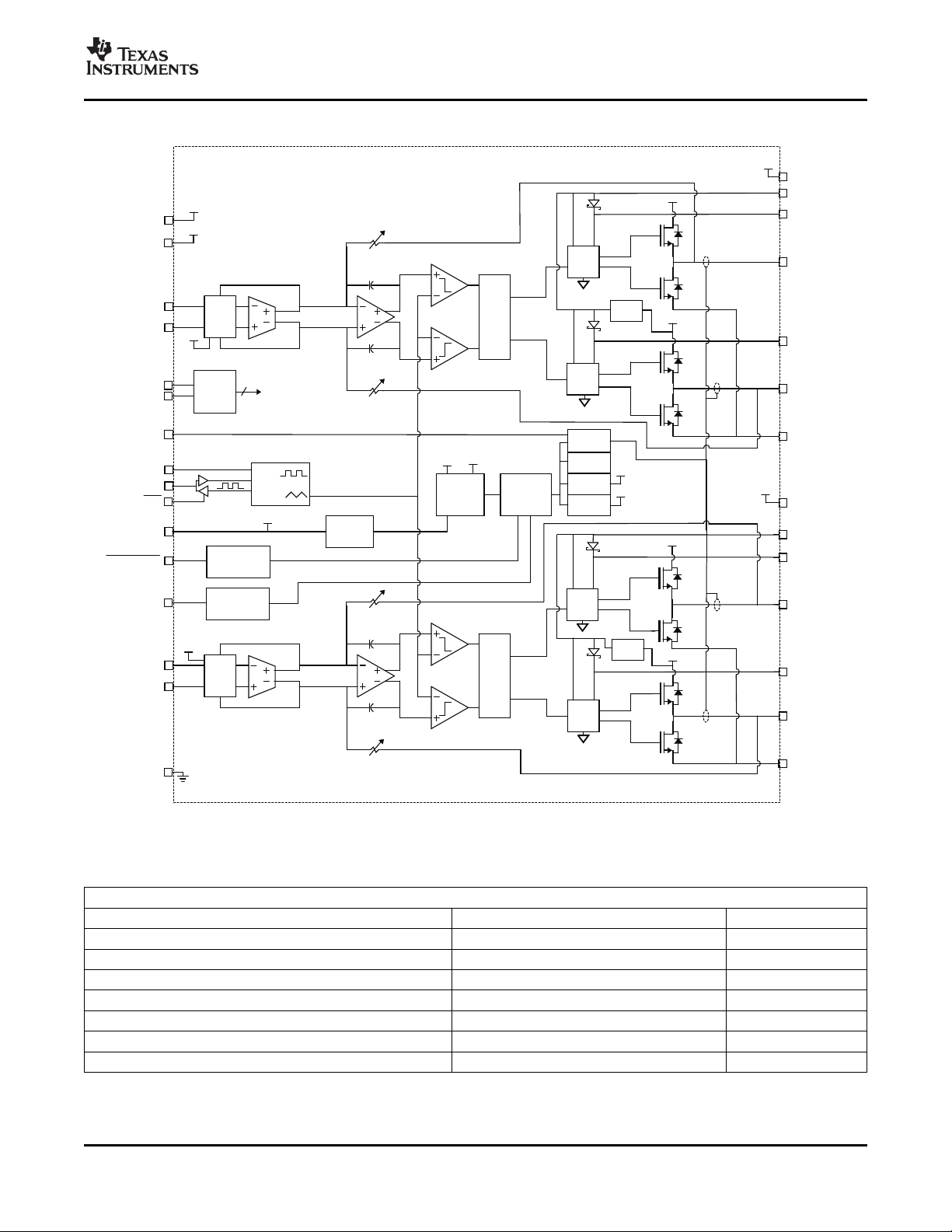
FUNCTIONAL BLOCK DIAGRAM
TPA3101D2
SLOS473B – DECEMBER 2005 – REVISED SEPTEMBER 2007
FIGURE
(1)
TYPICAL CHARACTERISTICS
TABLE OF GRAPHS
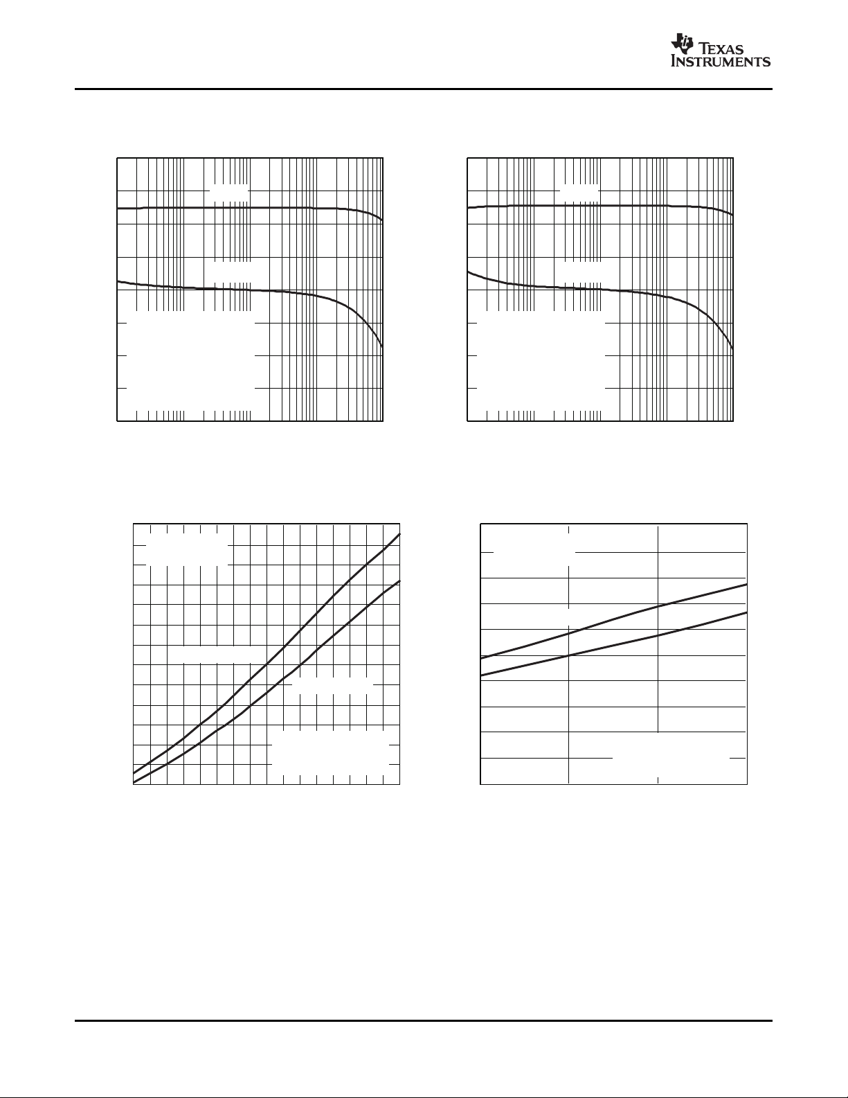
Closed-loop response vs Frequency 9, 10
Output power vs Supply voltage 11. 12
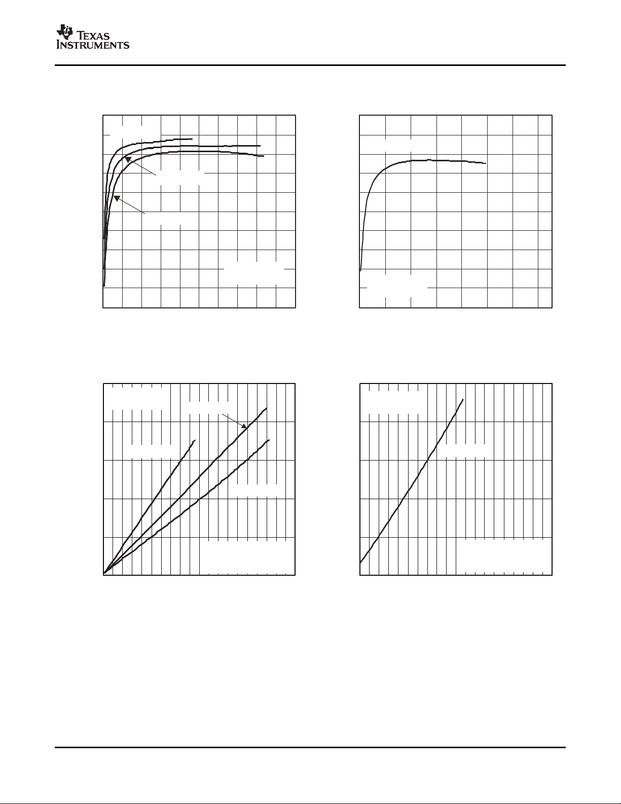
Efficiency vs Output power 13, 14
Supply current vs Total output power 15, 16
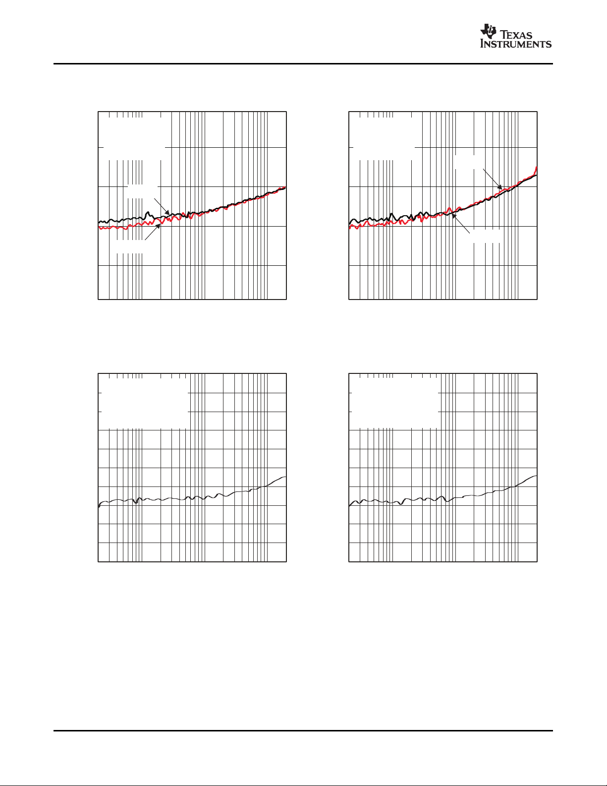
Crosstalk vs Frequency 17, 18
Supply ripple rejection ratio vs Frequency 19, 20
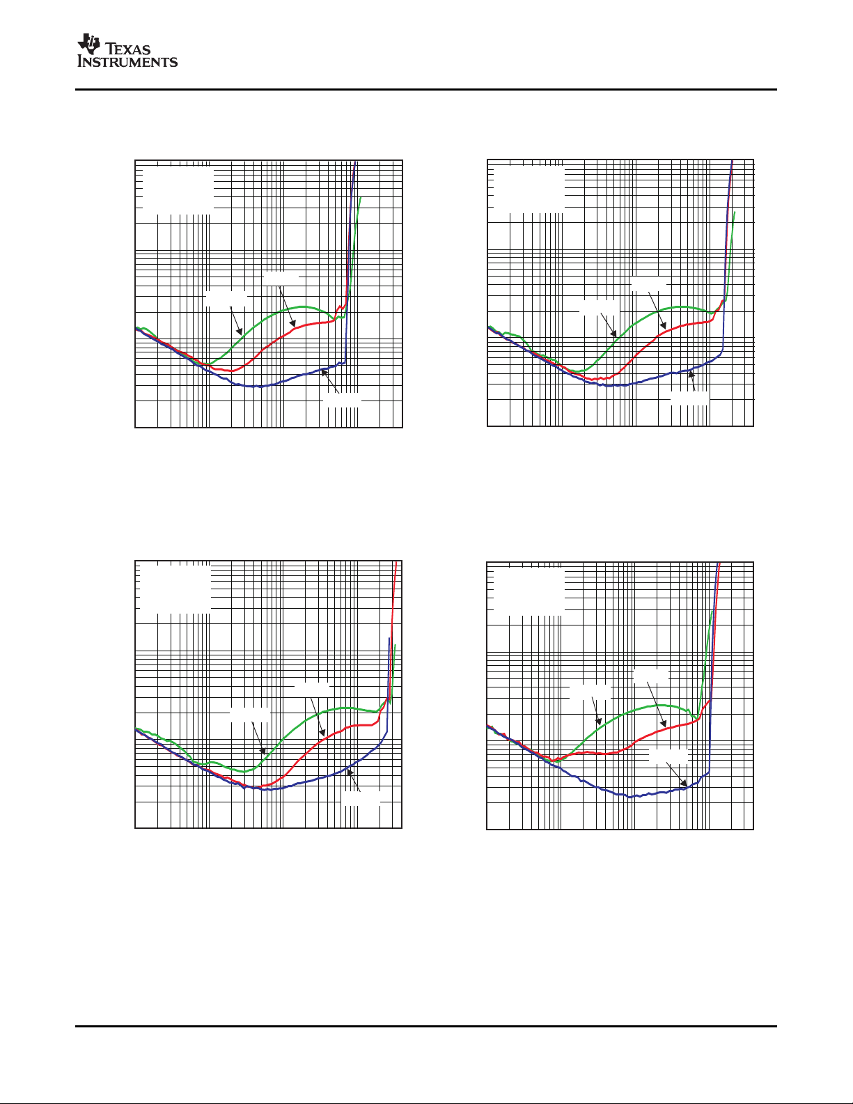
THD+N Total harmonic distortion + noise vs Frequency 1, 2, 3, 4
THD+N Total harmonic distortion + noise vs Output power 5, 6, 7, 8
V
CC
k
SVR
(1) All graphs were measured using the TPA3101D2 EVM.
Copyright © 2005 – 2007, Texas Instruments Incorporated Submit Documentation Feedback 7
Product Folder Link(s): TPA3101D2
Page 8
www.ti.com
0.003
10
0.005
0.01
0.02
0.05
0.1
0.2
0.5
1
2
5
THD-TotalHarmonicDistortion-%
20 20k50 100 200 500 1k 2k 5k 10k
f-Frequency-Hz
V =18V,
R =8 ,
Gain=20dB
CC
L
W
P =2.5W
O
P =1W
O
P =10W
O
20 20k50 100 200 500 1k 2k 5k 10k
f-Frequency-Hz
0.003
10
0.005
0.01
0.02
0.05
0.1
0.2
0.5
1
2
5
THD-TotalHarmonicDistortion-%
V =12V,
R =8 ,
Gain=20dB
CC
L
W
P =5W
O
P =2.5W
O
P =1W
O
0.003
10
0.005
0.01
0.02
0.05
0.1
0.2
0.5
1
2
5
THD-TotalHarmonicDistortion-%
20 20k50 100 200 500 1k 2k 5k 10k
f-Frequency-Hz
V =24V,
R =8 ,
Gain=20dB
CC
L
W
P =5W
O
P =10W
O
P =1W
O
0.003
10
0.005
0.01
0.02
0.05
0.1
0.2
0.5
1
2
5
THD-TotalHarmonicDistortion-%
20 20k50 100 200 500 1k 2k 5k 10k
f-Frequency-Hz
V =12V,
R =4 ,
Gain=20dB
CC
L
W
P =2.5W
O
P =1W
O
TPA3101D2
SLOS473B – DECEMBER 2005 – REVISED SEPTEMBER 2007
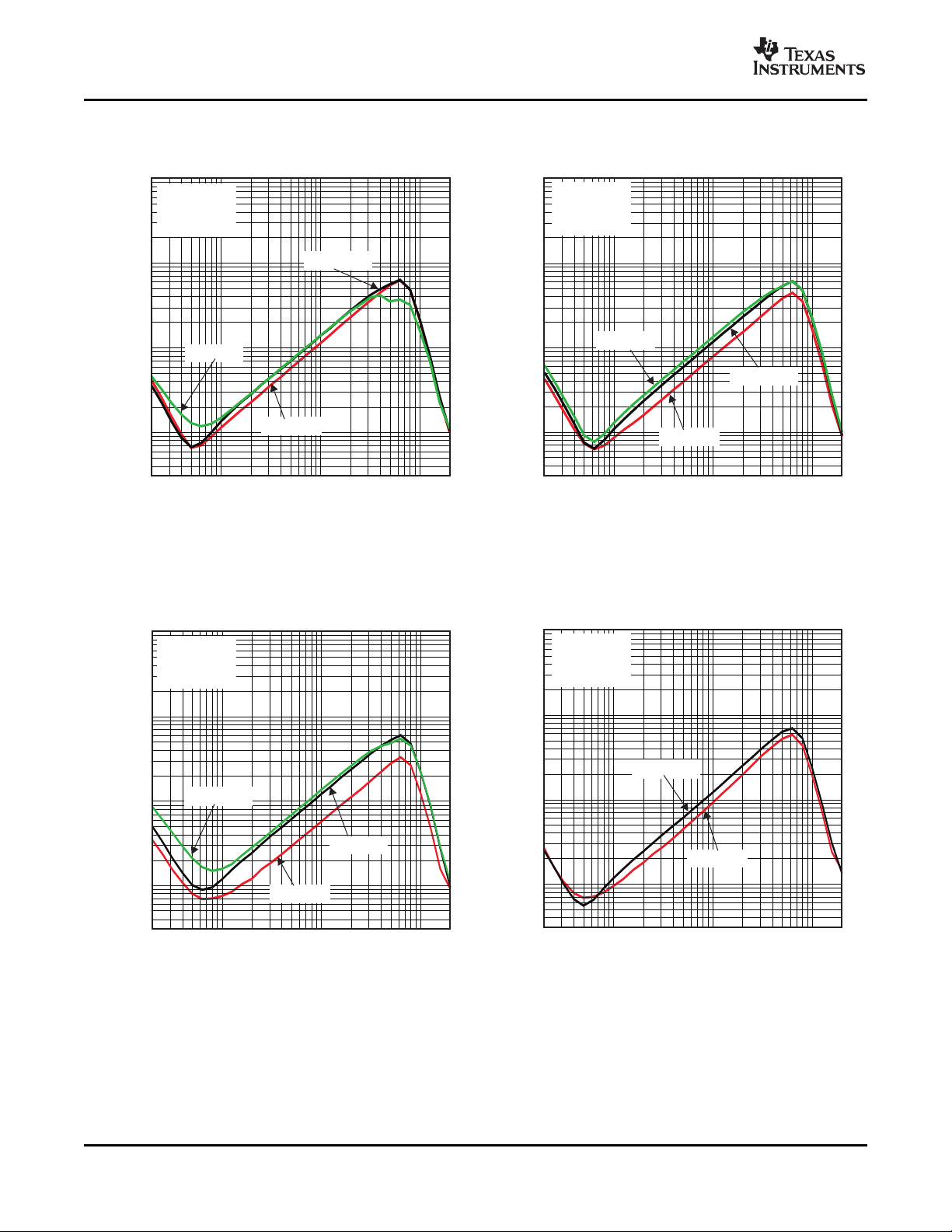
TOTAL HARMONIC DISTORTION + NOISE TOTAL HARMONIC DISTORTION + NOISE
vs vs
FREQUENCY FREQUENCY
NOTE: Power above 10 W may require increased NOTE: Power above 10 W may require increased
heatsinking. heatsinking.
Figure 1. Figure 2.
TOTAL HARMONIC DISTORTION + NOISE TOTAL HARMONIC DISTORTION + NOISE
NOTE: Power above 10 W may require increased NOTE: Power above 10 W may require increased
heatsinking. heatsinking.
8 Submit Documentation Feedback Copyright © 2005 – 2007, Texas Instruments Incorporated
vs vs
FREQUENCY FREQUENCY
Figure 3. Figure 4.
Product Folder Link(s): TPA3101D2
Page 9
www.ti.com
0.01
10
0.02
0.05
0.1
0.2
0.5
1
2
5
THD-TotalHarmonicDistortion-%
10m 4050m 100m 200m 1 2 5 10 20
P -OutputPower-W
O
10kHz
20Hz
1kHz
V =18V,
R =8 ,
Gain=32dB
CC
L
W
10m 4050m 100m 200m 1 2 5 10 20
P -OutputPower-W
O
0.01
10
0.02
0.05
0.1
0.2
0.5
1
2
5
THD-TotalHarmonicDistortion-%
10kHz
20Hz
1kHz
V =12V,
R =8 ,
Gain=32dB
CC
L
W
0.01
10
0.02
0.05
0.1
0.2
0.5
1
2
5
THD-TotalHarmonicDistortion-%
10m 4050m 100m 200m 1 2 5 10 20
P -OutputPower-W
O
10kHz
20Hz
1kHz
V =24V,
R =8 ,
Gain=32dB
CC
L
W
0.01
10
0.02
0.05
0.1
0.2
0.5
1
2
5
THD-TotalHarmonicDistortion-%
10m 4050m 100m 200m 1 2 5 10 20
P -OutputPower-W
O
V =12V,
R =4 ,
Gain=32dB
CC
L
W
10kHz
20Hz
1kHz
TPA3101D2
SLOS473B – DECEMBER 2005 – REVISED SEPTEMBER 2007
TOTAL HARMONIC DISTORTION + NOISE TOTAL HARMONIC DISTORTION + NOISE
vs vs
OUTPUT POWER OUTPUT POWER
NOTE: Power above 10 W may require increased NOTE: Power above 10 W may require increased
heatsinking. heatsinking.
Figure 5. Figure 6.
TOTAL HARMONIC DISTORTION + NOISE TOTAL HARMONIC DISTORTION + NOISE
vs vs
OUTPUT POWER OUTPUT POWER
NOTE: Power above 10 W may require increased NOTE: Power above 10 W may require increased
heatsinking. heatsinking.
Copyright © 2005 – 2007, Texas Instruments Incorporated Submit Documentation Feedback 9
Figure 7. Figure 8.
Product Folder Link(s): TPA3101D2
Page 10
www.ti.com
-200
200
-150
-100
-50
0
50
100
150
0
40
5
10
15
20
25
30
35
f-Frequency-Hz
10 100 1k 10k 100k
Gain
−
dB
Phase
−
o
Gain
Phase
V =12V
R =8
V =0.1V
C =10 F
Gain=32dB
RCfilter=100 ,10nF
CC
L
I rms
I
W
m
W
-200
200
-150
-100
-50
0
50
100
150
0
40
5
10
15
20
25
30
35
f-Frequency-Hz
10 100 1k 10k 100k
Gain
−
dB
Phase
−
o
Gain
Phase
V =24V
R =8
V =0.1V
C =10 F
Gain=32dB
RCfilter=100 ,10nF
CC
L
I rms
I
W
m
W
V -SupplyVoltage-V
CC
5
7.5
10
12.5
15
17.5
22.5
20
30
25
35
27.5
32.5
37.5
10
12 14
16
18 20 22
24 26
P
O
−
OutputPower
−
W
THD+N=10%
THD+N=1%
R =8
Gain=20dB
L
W
PowerBeyond10W
MayRequireMore
Heatsinking.
V -SupplyVoltage-V
CC
0
2
4
6
8
10
12
18
14
16
20
10
11 12
13
P
O
−
OutputPower
−
W
THD+N=10%
THD+N=1%
R =4
Gain=20dB
L
W
PowerBeyond10W
MayRequireMore
Heatsinking.
TPA3101D2
SLOS473B – DECEMBER 2005 – REVISED SEPTEMBER 2007
CLOSED LOOP RESPONSE CLOSED LOOP RESPONSE
vs vs
FREQUENCY FREQUENCY
Figure 9. Figure 10.
OUTPUT POWER OUTPUT POWER
vs vs
SUPPLY VOLTAGE SUPPLY VOLTAGE
10 Submit Documentation Feedback Copyright © 2005 – 2007, Texas Instruments Incorporated
Figure 11. Figure 12.
Product Folder Link(s): TPA3101D2
Page 11
www.ti.com
PO− OutputPower(PerChannel) − W
0
10
20
30
40
50
60
70
80
90
100
0 2 4 6 8 10 12 14 16 18 20
RL=8 W
Gain=20dB
Efficiency
−
%
VCC=24V
V =18V
CC
VCC=12V
PO− OutputPower(PerChannel) − W
0
10
20
30
40
50
60
70
80
90
100
0 2 4 6 8 10 12 14 15
RL=4 Ω
Gain=32dB
Efficiency
−
%
VCC=12V
PO− TotalOutputPower − W
0
0.5
1
1.5
2
2.5
0 10 20 30 40
RL=8 Ω
Gain=32dB
I
C
C
−
SupplyCurrent
−
A
VCC=24V
VCC=12V
VCC=18V
PowerBeyond10W
MayRequireMore
Heatsinking.
PO− TotalOutputPower − W
0
0.5
1
1.5
2
2.5
0 10 20 30 40
RL=4 Ω
Gain=32dB
I
C
C
−
SupplyCurrent
−
A
VCC=12V
PowerBeyond10W
MayRequireMore
Heatsinking.
SLOS473B – DECEMBER 2005 – REVISED SEPTEMBER 2007
EFFICIENCY EFFICIENCY
vs vs
OUTPUT POWER OUTPUT POWER
TPA3101D2
SUPPLY CURRENT SUPPLY CURRENT
TOTAL OUTPUT POWER TOTAL OUTPUT POWER
Copyright © 2005 – 2007, Texas Instruments Incorporated Submit Documentation Feedback 11
Figure 13. Figure 14.
vs vs
Figure 15. Figure 16.
Product Folder Link(s): TPA3101D2
Page 12
www.ti.com
−140
−120
−100
−80
−60
-40
f − Frequency − Hz
Crosstalk
−
dB
20 100 1k 10k 20k
VCC=12V
RL=8 Ω
Gain=20dB
V =1Vrms
O
L toR
RtoL
−140
−120
−100
−80
−60
-40
f − Frequency − Hz
Crosstalk
−
dB
20 100 1k 10k 20k
VCC=24V
RL=8 Ω
Gain=20dB
V =1Vrms
O
L toR
RtoL
−100
−90
−80
−70
−60
−50
−40
−30
−20
−10
0
f − Frequency − Hz
k
S
V
R
−
SupplyRippleRejectionRatio
−
dB
20 100 1k 10k 20k
V =12V
CC
R =8
Gain=20dB
V =200mV
L
(RIPPLE) PP
W
−100
−90
−80
−70
−60
−50
−40
−30
−20
−10
0
f − Frequency − Hz
k
S
V
R
−
SupplyRippleRejectionRatio
−
dB
20 100 1k 10k 20k
V =18V
CC
R =8
Gain=20dB
V =200mV
L
(RIPPLE) PP
W
TPA3101D2
SLOS473B – DECEMBER 2005 – REVISED SEPTEMBER 2007
CROSSTALK CROSSTALK
vs vs
FREQUENCY FREQUENCY
Figure 17. Figure 18.
SUPPLY RIPPLE REJECTION RATIO SUPPLY RIPPLE REJECTION RATIO
vs vs
FREQUENCY FREQUENCY
Figure 19. Figure 20.
12 Submit Documentation Feedback Copyright © 2005 – 2007, Texas Instruments Incorporated
Product Folder Link(s): TPA3101D2
Page 13
www.ti.com
TPA3101D2
GAIN1
LINP
RINN
RINP
AGND
LINN
GAIN0
SYNC
MSTR/SLV
NC
NC
NC
AVCC
NC
FAULT
MUTE
SHUTDOWN
BSRP
ROUTP
ROUTP
ROUTN
ROUTN
BSRN
NC
10V-26V
NC
VREG
VBYP
AGND
BSLP
LOUTP
LOUTP
LOUTN
LOUTN
BSLN
NC
ROSC
220nF 220nF
220nF
220nF
PVCCR
NC
NC
PGNDR
PVCCR
PGNDR
VCLAMPR
VCLAMPL
PVCCL
PGNDL
PGNDL
PVCCL
10V-26V
10V-26V
FaultOutput
Shutdown
andMute
Control
10 Fm
33 Hm
33 Hm
1 Fm
1 Fm
1 Fm
1 Fm
1 Fm
220 Fm
1 Fm
1 Fm
1 Fm
220 Fm
1 Fm
1 Fm
10nF
100kW
1 Fm
1 Fm
Differential
Analog
Inputs
4-Step
GainControl
SynchronizeMultiple
Class-DDevices
33 Hm
33 Hm
1 Fm
8 W
8 W
1 Fm
470pF
470pF
20 W
20 W
20 W
20 W
20 W
470pF
470pF
TPA3101D2
SLOS473B – DECEMBER 2005 – REVISED SEPTEMBER 2007
APPLICATION INFORMATION
Figure 21. Stereo Class-D With Differential Inputs (QFN)
Copyright © 2005 – 2007, Texas Instruments Incorporated Submit Documentation Feedback 13
Product Folder Link(s): TPA3101D2
Page 14

www.ti.com
TPA3101D2
GAIN1
LINP
RINN
RINP
AGND
LINN
GAIN0
SYNC
MSTR/SLV
NC
NC
NC
AVCC
NC
FAULT
MUTE
SHUTDOWN
BSRP
ROUTP
ROUTP
ROUTN
ROUTN
BSRN
NC
10V-26V
NC
VREG
VBYP
AGND
BSLP
LOUTP
LOUTP
LOUTN
LOUTN
BSLN
NC
ROSC
220nF 220nF
220nF
220nF
PVCCR
NC
NC
PGNDR
PVCCR
PGNDR
VCLAMPR
VCLAMPL
PVCCL
PGNDL
PGNDL
PVCCL
10V-26V
10V-26V
FaultOutput
Shutdown
andMute
Control
10 Fm
33 Hm
33 Hm
1 Fm
1 Fm
1 Fm
1 Fm
1 Fm
220 Fm
1 Fm
1 Fm
1 Fm
220 Fm
1 Fm
1 Fm
10nF
100kW
1 Fm
1 Fm
Single-Ended
Analog
Inputs
4-Step
GainControl
SynchronizeMultiple
Class-DDevices
33 Hm
33 Hm
1 Fm
8 W
8 W
1 Fm
20 W
470pF
20 W
470pF
20 W
470pF
470pF
20 W
TPA3101D2
SLOS473B – DECEMBER 2005 – REVISED SEPTEMBER 2007
Figure 22. Stereo Class-D With Single-Ended Inputs (QFN)
14 Submit Documentation Feedback Copyright © 2005 – 2007, Texas Instruments Incorporated
Product Folder Link(s): TPA3101D2
Page 15

www.ti.com
TPA3101D2
GAIN1
LINP
RINN
RINP
AGND
LINN
GAIN0
SYNC
MSTR/SLV
GND
GAIN0
GND
AVCC
A
VCC
FAULT
MUTE
SHUTDOWN
BSRP
ROUTP
ROUTP
ROUTN
ROUTN
BSRN
GND
10V-26V
GND
VREG
VBYP
AGND
BSLP
LOUTP
LOUTP
LOUTN
LOUTN
BSLN
GND
ROSC
220nF 220nF
220nF
220nF
PVCCR
GND
GND
PGNDR
PVCCR
PGNDR
VCLAMPR
VCLAMPL
PVCCL
PGNDL
PGNDL
PVCCL
10V-26V
10V-26V
FaultOutput
Shutdown
andMute
Control
10 Fm
33 Hm
33 Hm
1 Fm
1 Fm
1 Fm
1 Fm
1 Fm
220 Fm
1 Fm
1 Fm
1 Fm
220 Fm
1 Fm
1 Fm
10nF
100kW
1 Fm
1 Fm
Differential
Analog
Inputs
4-Step
GainControl
SynchronizeMultiple
Class-DDevices
33 Hm
33 Hm
1 Fm
8 W
8 W
1 Fm
470pF
20 W
470pF
20 W
470pF
20 W
470pF
20 W
TPA3101D2
SLOS473B – DECEMBER 2005 – REVISED SEPTEMBER 2007
Figure 23. Stereo Class-D With Differential Inputs (HTQFP)
Copyright © 2005 – 2007, Texas Instruments Incorporated Submit Documentation Feedback 15
Product Folder Link(s): TPA3101D2
Page 16

www.ti.com
TPA3101D2
GAIN1
LINP
RINN
RINP
AGND
LINN
GAIN0
SYNC
MSTR/SLV
GND
GAIN0
GND
AVCC
A
VCC
FAULT
MUTE
SHUTDOWN
BSRP
ROUTP
ROUTP
ROUTN
ROUTN
BSRN
GND
10V-26V
GND
VREG
VBYP
AGND
BSLP
LOUTP
LOUTP
LOUTN
LOUTN
BSLN
GND
ROSC
220nF
220nF
220nF
220nF
PVCCR
GND
GND
PGNDR
PVCCR
PGNDR
VCLAMPR
VCLAMPL
PVCCL
PGNDL
PGNDL
PVCCL
10V-26V
10V-26V
FaultOutput
Shutdown
andMute
Control
10 Fm
33 Hm
33 Hm
1 Fm
1 Fm
1 Fm
1 Fm
1 Fm
220 Fm
1 Fm
1 Fm
1 Fm
220 Fm
1 Fm
1 Fm
10nF
100kW
1 Fm
1 Fm
Single-Ended
Analog
Inputs
4-Step
GainControl
SynchronizeMultiple
Class-DDevices
33 Hm
33 Hm
8 W
8 W
20 W
470pF
470pF
20 W
470pF
20 W
470pF
20 W
1 Fm
1 Fm
TPA3101D2
SLOS473B – DECEMBER 2005 – REVISED SEPTEMBER 2007
Figure 24. Stereo Class-D With Single-Ended Inputs (HTQFP)
16 Submit Documentation Feedback Copyright © 2005 – 2007, Texas Instruments Incorporated
Product Folder Link(s): TPA3101D2
Page 17

www.ti.com
0V
-12V
+12V
Current
OUTP
DifferentialVoltage
AcrossLoad
OUTN
TPA3101D2
SLOS473B – DECEMBER 2005 – REVISED SEPTEMBER 2007
CLASS-D OPERATION
This section focuses on the class-D operation of the TPA3101D2.
Traditional Class-D Modulation Scheme
The traditional class-D modulation scheme, which is used in the TPA032D0x family, has a differential output
where each output is 180 degrees out of phase and changes from ground to the supply voltage, V
the differential prefiltered output varies between positive and negative V
, where filtered 50% duty cycle yields
CC
0 V across the load. The traditional class-D modulation scheme with voltage and current waveforms is shown in
Figure 25 . Note that even at an average of 0 V across the load (50% duty cycle), the current to the load is high,
causing high loss and thus causing a high supply current.
. Therefore,
CC
TPA3101D2 Modulation Scheme
The TPA3101D2 uses a modulation scheme that still has each output switching from 0 to the supply voltage.
However, OUTP and OUTN are now in phase with each other with no input. The duty cycle of OUTP is greater
than 50% and OUTN is less than 50% for positive output voltages. The duty cycle of OUTP is less than 50% and
OUTN is greater than 50% for negative output voltages. The voltage across the load sits at 0 V throughout most
of the switching period, greatly reducing the switching current, which reduces any I2R losses in the load.
Figure 25. Traditional Class-D Modulation Scheme's Output Voltage and Current Waveforms into an
Inductive Load With No Input
Copyright © 2005 – 2007, Texas Instruments Incorporated Submit Documentation Feedback 17
Product Folder Link(s): TPA3101D2
Page 18

www.ti.com
0V
-12V
+12V
Current
OUTP
OUTN
Differential
Voltage
Across
Load
0V
-12V
+12V
Current
OUTP
OUTN
Differential
Voltage
Across
Load
Output=0V
Output>0V
TPA3101D2
SLOS473B – DECEMBER 2005 – REVISED SEPTEMBER 2007
Figure 26. The TPA3101D2 Output Voltage and Current Waveforms Into an Inductive Load
Efficiency: LC Filter Required With the Traditional Class-D Modulation Scheme
The main reason that the traditional class-D amplifier needs an output filter is that the switching waveform results
in maximum current flow. This causes more loss in the load, which causes lower efficiency. The ripple current is
large for the traditional modulation scheme, because the ripple current is proportional to voltage multiplied by the
time at that voltage. The differential voltage swing is 2 x V
the traditional modulation scheme. An ideal LC filter is needed to store the ripple current from each half cycle for
the next half cycle, while any resistance causes power dissipation. The speaker is both resistive and reactive,
whereas an LC filter is almost purely reactive.
The TPA3101D2 modulation scheme has little loss in the load without a filter because the pulses are short and
the change in voltage is V
instead of 2 x V
CC
. As the output power increases, the pulses widen, making the
CC
, and the time at each voltage is half the period for
CC
ripple current larger. Ripple current could be filtered with an LC filter for increased efficiency, but for most
applications the filter is not needed.
An LC filter with a cutoff frequency less than the class-D switching frequency allows the switching current to flow
through the filter instead of the load. The filter has less resistance but higher impedance at the switching
frequency than the speaker, which results in less power dissipation, therefore increasing efficiency.
When to Use an Output Filter for EMI Suppression
Design the TPA3101D2 without the filter if the traces from amplifier to speaker are short (< 10 cm). Powered
speakers, where the speaker is in the same enclosure as the amplifier, is a typical application for class-D without
a filter.
18 Submit Documentation Feedback Copyright © 2005 – 2007, Texas Instruments Incorporated
Product Folder Link(s): TPA3101D2
Page 19

www.ti.com
1 mF
1 mF
33 Hm
33 mH
OUTP
OUTN
L1
L2
C2
C3
2.2 mF
2.2 mF
15 Hm
15 mH
OUTP
OUTN
L1
L2
C2
C3
1nF
Ferrite
ChipBead
OUTP
OUTN
Ferrite
ChipBead
1nF
TPA3101D2
SLOS473B – DECEMBER 2005 – REVISED SEPTEMBER 2007
Most applications require a ferrite bead filter. The ferrite filter reduces EMI around 1 MHz and higher (FCC and
CE only test radiated emissions greater than 30 MHz). When selecting a ferrite bead, choose one with high
impedance at high frequencies, but low impedance at low frequencies.
Use an LC output filter if there are low frequency (<1 MHz) EMI-sensitive circuits and/or there are long wires
from the amplifier to the speaker.
When both an LC filter and a ferrite bead filter are used, the LC filter should be placed as close as possible to
the IC followed by the ferrite bead filter.
Figure 27. Typical LC Output Filter, Cutoff Frequency of 28 kHz, Speaker Impedance = 8 Ω
Figure 28. Typical LC Output Filter, Cutoff Frequency of 28 kHz, Speaker Impedance = 4 Ω
Figure 29. Typical Ferrite Chip Bead Filter (Chip Bead Example: Fair-Rite 2512067007Y3)
Copyright © 2005 – 2007, Texas Instruments Incorporated Submit Documentation Feedback 19
Product Folder Link(s): TPA3101D2
Page 20

www.ti.com
0
f − Frequency − Hz
10
20
30
40
50
60
70
30M 230M 430M 630M 830M
LimitLevel
−
dB(
V
in)
m
NationalTechnicalSystems,PlanoTx
RadiatedEmissions30MHz-1000MHz
FCCBLimits
FCCBLimit
PeakdB
-10
TPA3101D2
SLOS473B – DECEMBER 2005 – REVISED SEPTEMBER 2007
Using the LC filter in Figure 27 , the TPA3101D2 EVM passed the FCC Part 15 Class B radiated emissions test
with 21 inch speaker wires. Quasi-peak measurements were taken for the 4 standard test configurations, and the
TPA3101D2 EVM passed with at least 14-dB margin. A plot of the peak measurement for the horizontal rear
configuration is shown in Figure 30 .
Figure 30. Radiated Emissions Prescan 30 MHz - 1000 MHz
Inductors used in LC filters must be chosen carefully. A significant change in inductance at the peak output
current of the TPA3101D2 will cause increased distortion. The change of inductance at currents up to the peak
output current must be less than 0.1 μ H per amp to avoid this. Also note that smaller inductors than 33 μ H may
cause an increase in distortion above what is shown in preceding graphs of THD versus frequency and output
power.
Capacitors used in LC filters must also be chosen carefully. A significant change in capacitance at the peak
output voltage of the TPA3101D2 will cause increased distortion. LC filter capacitors should have DC-voltage
ratings of at least twice the peak application voltage (the power supply voltage) and should be made of X5R or
better material. In all cases, avoid using capacitors with loose temperature ratings like Y5V.
20 Submit Documentation Feedback Copyright © 2005 – 2007, Texas Instruments Incorporated
Product Folder Link(s): TPA3101D2
Page 21

www.ti.com
Adaptive Dynamic Range Control
TPA3101D2
ClosestCompetitor
t-Time=100 s/divm
V-Voltage=10V/div
TPA3101D2
ClosestCompetitor
t-Time=20 s/divm
V-Voltage=1V/div
Figure 31. 1-kHz Sine Output at 10% THD+N Figure 32. 8-kHz Sine Output at 10% THD+N
TPA3101D2
SLOS473B – DECEMBER 2005 – REVISED SEPTEMBER 2007
The Texas Instruments patent-pending adaptive dynamic range control (ADRC) technology removes the notch
inherent in class-D audio power amplifiers when they come out of clipping. This effect is more severe at higher
frequencies as shown in Figure 32 .
Gain setting via GAIN0 and GAIN1 inputs
The gain of the TPA3101D2 is set by two input terminals, GAIN0 and GAIN1.
The gains listed in Table 1 are realized by changing the taps on the input resistors and feedback resistors inside
the amplifier. This causes the input impedance (Z
are controlled by ratios of resistors, so the gain variation from part-to-part is small. However, the input impedance
from part-to-part at the same gain may shift by ± 20% due to shifts in the actual resistance of the input resistors.
For design purposes, the input network (discussed in the next section) should be designed assuming an input
impedance of 12.8 k Ω , which is the absolute minimum input impedance of the TPA3101D2. At the lower gain
settings, the input impedance could increase as high as 38.4 k Ω
GAIN1 GAIN0
0 0 20 32
0 1 26 16
1 0 32 16
1 1 36 16
) to be dependent on the gain setting. The actual gain settings
I
Table 1. Gain Setting
AMPLIFIER GAIN (dB)
TYP TYP
INPUT IMPEDANCE
(k Ω )
INPUT RESISTANCE
Changing the gain setting can vary the input resistance of the amplifier from its smallest value, 16 k Ω ± 20%, to
the largest value, 32 k Ω ± 20%. As a result, if a single capacitor is used in the input high-pass filter, the -3 dB or
cutoff frequency may change when changing gain steps.
Copyright © 2005 – 2007, Texas Instruments Incorporated Submit Documentation Feedback 21
Product Folder Link(s): TPA3101D2
Page 22

www.ti.com
C
i
IN
Z
i
Z
f
Input
Signal
f=
1
2 Z Cp
i i
f =
c
1
2 Z Cp
i i
-3dB
f
c
C =
i
1
2 Z fp
i c
TPA3101D2
SLOS473B – DECEMBER 2005 – REVISED SEPTEMBER 2007
The -3-dB frequency can be calculated using Equation 1 . Use the ZIvalues given in Table 1 .
(1)
INPUT CAPACITOR, C
In the typical application, an input capacitor (C
proper dc level for optimum operation. In this case, C
I
) is required to allow the amplifier to bias the input signal to the
I
and the input impedance of the amplifier (Z
I
) form a
I
high-pass filter with the corner frequency determined in Equation 2 .
The value of C
is important, as it directly affects the bass (low-frequency) performance of the circuit. Consider
I
the example where ZIis 20 k Ω and the specification calls for a flat bass response down to 20 Hz. Equation 2 is
reconfigured as Equation 3 .
In this example, CIis 0.4 µF; so, one would likely choose a value of 0.47 μ F as this value is commonly used. If
the gain is known and is constant, use ZIfrom Table 1 to calculate CI. A further consideration for this capacitor is
the leakage path from the input source through the input network (C
) and the feedback network to the load. This
I
leakage current creates a dc offset voltage at the input to the amplifier that reduces useful headroom, especially
in high gain applications. For this reason, a low-leakage tantalum or ceramic capacitor is the best choice. When
polarized capacitors are used, the positive side of the capacitor should face the amplifier input in most
applications as the dc level there is held at 2 V, which is likely higher than the source dc level. Note that it is
important to confirm the capacitor polarity in the application. Additionally, lead-free solder can create dc offset
voltages and it is important to ensure that boards are cleaned properly.
(2)
(3)
Power Supply Decoupling, C
S
The TPA3101D2 is a high-performance CMOS audio amplifier that requires adequate power supply decoupling
to ensure that the output total harmonic distortion (THD) is as low as possible. Power supply decoupling also
prevents oscillations for long lead lengths between the amplifier and the speaker. The optimum decoupling is
achieved by using two capacitors of different types that target different types of noise on the power supply leads.
For higher frequency transients, spikes, or digital hash on the line, a good low equivalent-series-resistance (ESR)
ceramic capacitor, typically 0.1 μ F to 1 µF placed as close as possible to the device V
lead works best. For
CC
filtering lower frequency noise signals, a larger aluminum electrolytic capacitor of 220 μ F or greater placed near
the audio power amplifier is recommended. The 220 μ F capacitor also serves as local storage capacitor for
supplying current during large signal transients on the amplifier outputs. The PVCC terminals provide the power
to the output transistors, so a 220 µF or larger capacitor should be placed on each PVCC terminal. A 10 µF
capacitor on the AVCC terminal is adequate.
22 Submit Documentation Feedback Copyright © 2005 – 2007, Texas Instruments Incorporated
Product Folder Link(s): TPA3101D2
Page 23

www.ti.com
OUTP
OUTN
470pF 470pF
20 W 20 W
TPA3101D2
SLOS473B – DECEMBER 2005 – REVISED SEPTEMBER 2007
IC Output Snubbers
In Figure 33 , the 470-pF capacitors in series with 20- Ω resistors from the outputs of the TPA3101D2 IC to ground
are switching snubbers. They linearize switching transitions and reduce overshoot and ringing. By doing so they
improve THD+N at lower power levels and they improve EMC by 2 to 4 dB at middle frequencies. They increase
quiescent current by 3 to 12 mA depending on power supply voltage.
Figure 33. IC Output Snubbers
BSN and BSP Capacitors
The full H-bridge output stages use only NMOS transistors. Therefore, they require bootstrap capacitors for the
high side of each output to turn on correctly. A 220-nF ceramic capacitor, rated for at least 25 V, must be
connected from each output to its corresponding bootstrap input. Specifically, one 220-nF capacitor must be
connected from xOUTP to BSxx, and one 220-nF capacitor must be connected from xOUTN to BSxx. (See the
application circuit diagram in Figure 21 .)
The bootstrap capacitors connected between the BSxx pins and corresponding output function as a floating
power supply for the high-side N-channel power MOSFET gate drive circuitry. During each high-side switching
cycle, the bootstrap capacitors hold the gate-to-source voltage high enough to keep the high-side MOSFETs
turned on.
VCLAMP Capacitors
To ensure that the maximum gate-to-source voltage for the NMOS output transistors is not exceeded, two
internal regulators clamp the gate voltage. Two 1- μ F capacitors must be connected from VCLAMPL (pin 30) and
VCLAMPR (pin 31) to ground and must be rated for at least 16 V. The voltages at the VCLAMP terminals may
vary with V
and may not be used for powering any other circuitry.
CC
Internal Regulated 4-V Supply (VREG)
The VREG terminal (pin 15) is the output of an internally generated 4-V supply, used for the oscillator,
preamplifier, and gain control circuitry. It requires a 10-nF capacitor, placed close to the pin, to keep the regulator
stable.
This regulated voltage can be used to control GAIN0, GAIN1, MSTR/ SLV, and MUTE terminals, but should not
be used to drive external circuitry.
VBYP Capacitor Selection
The internal bias generator (VBYP) nominally provides a 1.25-V internal bias for the preamplifier stages. The
external input capacitors and this internal reference allow the inputs to be biased within the optimal
common-mode range of the input preamplifiers.
The selection of the capacitor value on the VBYP terminal is critical for achieving the best device performance.
During power up or recovery from the shutdown state, the VBYP capacitor determines the rate at which the
amplifier starts up. When the voltage on the VBYP capacitor equals VBYP, the device starts a 16.4-ms timer.
When this timer completes, the outputs start switching. The charge rate of the capacitor is calculated using the
standard charging formula for a capacitor, I = C x dV/dT. The charge current is nominally equal to 250µA and dV
is equal to VBYP. For example, a 1-µF capacitor on VBYP would take 5 ms to reach the value of VBYP and
begin a 16.4-ms count before the outputs turn on. This equates to a turn-on time of <30 ms for a 1-µF capacitor
on the VBYP terminal.
Copyright © 2005 – 2007, Texas Instruments Incorporated Submit Documentation Feedback 23
Product Folder Link(s): TPA3101D2
Page 24

www.ti.com
F =
OSC
1
2xROSCxCOSC
TPA3101D2
SLOS473B – DECEMBER 2005 – REVISED SEPTEMBER 2007
A secondary function of the VBYP capacitor is to filter high-frequency noise on the internal 1.25-V bias generator.
A value of at least 0.47µF is recommended for the VBYP capacitor. For the best power-up and shutdown pop
performance, the VBYP capacitor should be greater than or equal to the input capacitors.
ROSC Resistor Selection
The resistor connected to the ROSC terminal controls the class-D output switching frequency using Equation 4 :
COSC is an internal capacitor that is nominally equal to 20 pF. Variation over process and temperature can
result in a ± 15% change in this capacitor value.
For example, if ROSC is fixed at 100 k Ω , the frequency from device to device with this fixed resistance could
vary from 217 kHz to 294 kHz with a 15% variation in the internal COSC capacitor. The tolerance of the ROSC
resistor should also be considered to determine the range of expected switching frequencies from device to
device. It is recommended that 1% tolerance resistors be used.
Differential Input
The differential input stage of the amplifier cancels any noise that appears on both input lines of the channel. To
use the TPA3101D2 with a differential source, connect the positive lead of the audio source to the INP input and
the negative lead from the audio source to the INN input. To use the TPA3101D2 with a single-ended source, ac
ground the INP or INN input through a capacitor equal in value to the input capacitor on INN or INP and apply
the audio source to either input. In a single-ended input application, the unused input should be ac grounded at
the audio source instead of at the device input for best noise performance.
(4)
SHUTDOWN OPERATION
The TPA3101D2 employs a shutdown mode of operation designed to reduce supply current (I
minimum level during periods of nonuse for power conservation. The SHUTDOWN input terminal should be held
high (see specification table for trip point) during normal operation when the amplifier is in use. Pulling
SHUTDOWN low causes the outputs to mute and the amplifier to enter a low-current state. Never leave
SHUTDOWN unconnected, because amplifier operation would be unpredictable.
For the best power-off pop performance, place the amplifier in the shutdown or mute mode prior to removing the
power supply voltage.
) to the absolute
CC
MUTE Operation
The MUTE pin is an input for controlling the output state of the TPA3101D2. A logic high on this terminal
disables the outputs. A logic low on this pin enables the outputs. This terminal may be used as a quick
disable/enable of outputs when changing channels on a television or transitioning between different audio
sources.
The MUTE terminal should never be left floating. For power conservation, the SHUTDOWN terminal should be
used to reduce the quiescent current to the absolute minimum level.
The MUTE terminal can also be used with the FAULT output to automatically recover from a short-circuit event.
When a short-circuit event occurs, the FAULT terminal transitions high indicating a short-circuit has been
detected. When directly connected to MUTE, the MUTE terminal transitions high, and clears the internal fault
flag. This causes the FAULT terminal to cycle low, and normal device operation resumes if the short-circuit is
removed from the output. If a short remains at the output, the cycle continues until the short is removed.
If external MUTE control is desired, and automatic recovery from a short-circuit event is also desired, an OR gate
can be used to combine the functionality of the FAULT output and external MUTE control, see Figure 34 .
24 Submit Documentation Feedback Copyright © 2005 – 2007, Texas Instruments Incorporated
Product Folder Link(s): TPA3101D2
Page 25

www.ti.com
MUTE
FAULT
ExternalGPIO
Control
TPA3101D2
Figure 34. External MUTE Control
TPA3101D2
SLOS473B – DECEMBER 2005 – REVISED SEPTEMBER 2007
Copyright © 2005 – 2007, Texas Instruments Incorporated Submit Documentation Feedback 25
Product Folder Link(s): TPA3101D2
Page 26

www.ti.com
TPA3101D2
SLOS473B – DECEMBER 2005 – REVISED SEPTEMBER 2007
MSTR/ SLV and SYNC operation
The MSTR/ SLV and SYNC terminals can be used to synchronize the frequency of the class-D output switching.
When the MSTR/ SLV terminal is high, the output switching frequency is determined by the selection of the
resistor connected to the ROSC terminal (see ROSC Resistor Selection). The SYNC terminal becomes an output
in this mode, and the frequency of this output is also determined by the selection of the ROSC resistor. This TTL
compatible, push-pull output can be connected to another TPA3101D2, configured in the slave mode. The output
switching is synchronized to avoid any beat frequencies that could occur in the audio band when two class-D
amplifiers in the same system are switching at slightly different frequencies.
When the MSTR/ SLV terminal is low, the output switching frequency is determined by the incoming square wave
on the SYNC input. The SYNC terminal becomes an input in this mode and accepts a TTL compatible square
wave from another TPA3101D2 configured in the master mode or from an external GPIO. If connecting to an
external GPIO, recommended frequencies are 200 kHz to 300 kHz for proper device operation, and the
maximum amplitude is 4 V.
USING LOW-ESR CAPACITORS
Low-ESR capacitors are recommended throughout this application section. A real (as opposed to ideal) capacitor
can be modeled simply as a resistor in series with an ideal capacitor. The voltage drop across this resistor
minimizes the beneficial effects of the capacitor in the circuit. The lower the equivalent value of this resistance,
the more the real capacitor behaves like an ideal capacitor.
26 Submit Documentation Feedback Copyright © 2005 – 2007, Texas Instruments Incorporated
Product Folder Link(s): TPA3101D2
Page 27

www.ti.com
TPA3101D2
SLOS473B – DECEMBER 2005 – REVISED SEPTEMBER 2007
SHORT-CIRCUIT PROTECTION AND AUTOMATIC RECOVERY FEATURE
The TPA3101D2 has short-circuit protection circuitry on the outputs that prevents damage to the device during
output-to-output shorts, output-to-GND shorts, and output-to-V
outputs, the part immediately disables the output drive. This is a latched fault and must be reset by cycling the
voltage on the SHUTDOWN pin or MUTE pin. This clears the short-circuit flag and allows for normal operation if
the short was removed. If the short was not removed, the protection circuitry again activates.
The FAULT terminal can be used for automatic recovery from a short-circuit event, or used to monitor the status
with an external GPIO. For automatic recovery from a short-circuit event, connect the FAULT terminal directly to
the MUTE terminal. When a short-circuit event occurs, the FAULT terminal transitions high indicating a
short-circuit has been detected. When directly connected to MUTE, the MUTE terminal transitions high, and
clears the internal fault flag. This causes the FAULT terminal to cycle low, and normal device operation resumes
if the short-circuit is removed from the output. If a short remains at the output, the cycle continues until the short
is removed. If external MUTE control is desired, and automatic recovery from a short-circuit event is also desired,
an OR gate can be used to combine the functionality of the FAULT output and external MUTE control, see
Figure 34 .
THERMAL PROTECTION
Thermal protection on the TPA3101D2 prevents damage to the device when the internal die temperature
exceeds 150 ° C. There is a ± 15 ° C tolerance on this trip point from device to device. Once the die temperature
exceeds the thermal set point, the device enters into the shutdown state and the outputs are disabled. This is not
a latched fault. The thermal fault is cleared once the temperature of the die is reduced by 30 ° C. The device
begins normal operation at this point with no external system interaction.
shorts. When a short circuit is detected on the
CC
PRINTED-CIRCUIT BOARD (PCB) LAYOUT
Because the TPA3101D2 is a class-D amplifier that switches at a high frequency, the layout of the printed-circuit
board (PCB) should be optimized according to the following guidelines for the best possible performance.
• Decoupling capacitors — The high-frequency 1µF decoupling capacitors should be placed as close to the
PVCC (pins 26, 27, 34, and 35) and AVCC (pin 48) terminals as possible. The VBYP (pin 16) capacitor,
VREG (pin 15) capacitor, and VCLAMP (pins 30 and 31) capacitor should also be placed as close to the
device as possible. Large (220 µF or greater) bulk power supply decoupling capacitors should be placed near
the TPA3101D2 on the PVCCL, PVCCR, and AVCC terminals.
• Grounding — The AVCC (pin 48) decoupling capacitor, VREG (pin 15) capacitor, VBYP (pin 16) capacitor, and
ROSC (pin 14) resistor should each be grounded to analog ground (AGND, pin 17). The PVCC decoupling
capacitors and VCLAMP capacitors should each be grounded to power ground (PGND, pins 28, 29, 32, and
33). Analog ground and power ground should be connected at the thermal pad, which should be used as a
central ground connection or star ground for the TPA3101D2.
• Output filter — The ferrite EMI filter (Figure 29 ) should be placed as close to the output terminals as possible
for the best EMI performance. The LC filter (Figure 27 and Figure 28 ) should be placed close to the outputs.
The capacitors used in both the ferrite and LC filters should be grounded to power ground. If both filters are
used, the LC filter should be placed first, following the outputs.
• Thermal Pad — The thermal pad must be soldered to the PCB for proper thermal performance and optimal
reliability. The dimensions of the thermal pad and thermal land should be 5,1 mm by 5,1 mm. Five rows of
solid vias (five vias per row, 0,3302 mm or 13 mils diameter) should be equally spaced underneath the
thermal land. The vias should connect to a solid copper plane, either on an internal layer or on the bottom
layer of the PCB. The vias must be solid vias, not thermal relief or webbed vias. See TI Technical Briefs
SCBA017D and SLUA271 for more information about using the QFN thermal pad. See TI Technical Briefs
SLMA002 for more information about using the HTQFP thermal pad. For recommended PCB footprints, see
figures at the end of this data sheet.
For an example layout, see the TPA3101D2 Evaluation Module (TPA3101D2EVM) User Manual, (SLOU179).
Both the EVM user manual and the thermal pad application note are available on the TI Web site at
http://www.ti.com.
Copyright © 2005 – 2007, Texas Instruments Incorporated Submit Documentation Feedback 27
Product Folder Link(s): TPA3101D2
Page 28

www.ti.com
TPA3101D2
SLOS473B – DECEMBER 2005 – REVISED SEPTEMBER 2007
BASIC MEASUREMENT SYSTEM
This application note focuses on methods that use the basic equipment listed below:
• Audio analyzer or spectrum analyzer
• Digital multimeter (DMM)
• Oscilloscope
• Twisted-pair wires
• Signal generator
• Power resistor(s)
• Linear regulated power supply
• Filter components
• EVM or other complete audio circuit
Figure 35 shows the block diagrams of basic measurement systems for class-AB and class-D amplifiers. A sine
wave is normally used as the input signal because it consists of the fundamental frequency only (no other
harmonics are present). An analyzer is then connected to the APA output to measure the voltage output. The
analyzer must be capable of measuring the entire audio bandwidth. A regulated dc power supply is used to
reduce the noise and distortion injected into the APA through the power pins. A System Two audio measurement
system (AP-II) (Reference 1) by Audio Precision includes the signal generator and analyzer in one package.
The generator output and amplifier input must be ac-coupled. However, the EVMs already have the ac-coupling
capacitors, (C
attenuating the test signal, and is important because the input resistance of APAs is not high. Conversely, the
analyzer-input impedance should be high. The output resistance, R
milliohms and can be ignored for all but the power-related calculations.
Figure 35 (a) shows a class-AB amplifier system. It takes an analog signal input and produces an analog signal
output. This amplifier circuit can be directly connected to the AP-II or other analyzer input.
This is not true of the class-D amplifier system shown in Figure 35 (b), which requires low-pass filters in most
cases in order to measure the audio output waveforms. This is because it takes an analog input signal and
converts it into a pulse-width modulated (PWM) output signal that is not accurately processed by some
analyzers.
), so no additional coupling is required. The generator output impedance should be low to avoid
IN
, of the APA is normally in the hundreds of
OUT
28 Submit Documentation Feedback Copyright © 2005 – 2007, Texas Instruments Incorporated
Product Folder Link(s): TPA3101D2
Page 29

www.ti.com
Analyzer
20Hz-20kHz
(a)BasicClass-AB
APA
Signal
Generator
PowerSupply
Analyzer
20Hz-20kHz
R
L
(b)Filter-FreeandTraditionalClass-D
Class-D APA
Signal
Generator
PowerSupply
R
L
Low-PassRC
Filter
Low-PassRC
Filter
(Seenote A)
TPA3101D2
SLOS473B – DECEMBER 2005 – REVISED SEPTEMBER 2007
A. For efficiency measurements with filter-free Class-D, RLshould be an inductive load like a speaker.
Figure 35. Audio Measurement Systems
The TPA3101D2 uses a modulation scheme that does not require an output filter for operation, but they do
sometimes require an RC low-pass filter when making measurements. This is because some analyzer inputs
cannot accurately process the rapidly changing square-wave output and therefore record an extremely high level
of distortion. The RC low-pass measurement filter is used to remove the modulated waveforms so the analyzer
can measure the output sine wave.
DIFFERENTIAL INPUT AND BTL OUTPUT
All of the class-D APAs and many class-AB APAs have differential inputs and bridge-tied load (BTL) outputs.
Differential inputs have two input pins per channel and amplify the difference in voltage between the pins.
Differential inputs reduce the common-mode noise and distortion of the input circuit. BTL is a term commonly
used in audio to describe differential outputs. BTL outputs have two output pins providing voltages that are 180
degrees out of phase. The load is connected between these pins. This has the added benefits of quadrupling the
output power to the load and eliminating a dc blocking capacitor.
A block diagram of the measurement circuit is shown in Figure 36 . The differential input is a balanced input,
meaning the positive (+) and negative (-) pins have the same impedance to ground. Similarly, the BTL output
equates to a balanced output.
Copyright © 2005 – 2007, Texas Instruments Incorporated Submit Documentation Feedback 29
Product Folder Link(s): TPA3101D2
Page 30

www.ti.com
C
IN
AudioPower
Amplifier
Generator
Low-Pass
RCFilter
C
IN
R
GEN
R
GEN
R
IN
R
IN
V
GEN
R
OUT
R
OUT
Analyzer
R
ANA
R
ANA
C
ANA
Low-Pass
RCFilter
R
L
C
ANA
Twisted-PairWire
EvaluationModule
Twisted-PairWire
TPA3101D2
SLOS473B – DECEMBER 2005 – REVISED SEPTEMBER 2007
Figure 36. Differential Input, BTL Output Measurement Circuit
The generator should have balanced outputs, and the signal should be balanced for best results. An unbalanced
output can be used, but it may create a ground loop that affects the measurement accuracy. The analyzer must
also have balanced inputs for the system to be fully balanced, thereby cancelling out any common-mode noise in
the circuit and providing the most accurate measurement.
The following general rules should be followed when connecting to APAs with differential inputs and BTL outputs:
• Use a balanced source to supply the input signal.
• Use an analyzer with balanced inputs.
• Use twisted-pair wire for all connections.
• Use shielding when the system environment is noisy.
• Ensure that the cables from the power supply to the APA, and from the APA to the load, can handle the large
currents (see Table 2 ).
Table 2 shows the recommended wire size for the power supply and load cables of the APA system. The real
concern is the dc or ac power loss that occurs as the current flows through the cable. These recommendations
are based on 12-inch long wire with a 20-kHz sine-wave signal at 25 ° C.
Table 2. Recommended Minimum Wire Size for Power Cables
P
(W) RL( Ω ) AWG Size
OUT
10 4 18 22 16 40 18 42
2 4 18 22 3.2 8 3.7 8.5
1 8 22 28 2 8 2.1 8.1
< 0.75 8 22 28 1.5 6.1 1.6 6.2
DC POWER LOSS AC POWER LOSS
(MW) (MW)
CLASS-D RC LOW-PASS FILTER
An RC filter is used to reduce the square-wave output when the analyzer inputs cannot process the pulse-width
modulated class-D output waveform. This filter has little effect on the measurement accuracy because the cutoff
frequency is set above the audio band. The high frequency of the square wave has negligible impact on
measurement accuracy because it is well above the audible frequency range, and the speaker cone cannot
respond at such a fast rate. The RC filter is not required when an LC low-pass filter is used, such as with the
class-D APAs that employ the traditional modulation scheme (TPA032D0x, TPA005Dxx).
The component values of the RC filter are selected using the equivalent output circuit as shown in Figure 37 . R
is the load impedance that the APA is driving for the test. The analyzer input impedance specifications should be
available and substituted for R
system. The filter should be grounded to the APA near the output ground pins or at the power supply ground pin
to minimize ground loops.
30 Submit Documentation Feedback Copyright © 2005 – 2007, Texas Instruments Incorporated
and C
ANA
. The filter components, R
ANA
Product Folder Link(s): TPA3101D2
FILT
and C
, can then be derived for the
FILT
L
Page 31

www.ti.com
R
FILT
R
L
R
FILT
C
FILT
VL=V
IN
V
OUT
R
ANA
C
ANA
R
ANA
C
ANA
C
FILT
To APA
GND
AP AnalyzerInput
RCLow-PassFilters
Load
V
OUT
w
V
IN
w
O
R
ANA
+ R
FILT
R
ANA
1+j
(
(
(
)
)
)
=
f =
c
Ö2 x f
max
C =
FILT
1
2 xf xRp
c FILT
SLOS473B – DECEMBER 2005 – REVISED SEPTEMBER 2007
Figure 37. Measurement Low-Pass Filter Derivation Circuit-Class-D APAs
TPA3101D2
The transfer function for this circuit is shown in Equation 5 where ω
C
= (C
EQ
+ C
FILT
). The filter frequency should be set above f
ANA
MAX
, the highest frequency of the measurement
= R
C
O
, R
EQ
EQ
= R
EQ
|| R
FILT
ANA
bandwidth, to avoid attenuating the audio signal. Equation 6 provides this cutoff frequency, fC. The value of R
must be chosen large enough to minimize current that is shunted from the load, yet small enough to minimize the
attenuation of the analyzer-input voltage through the voltage divider formed by R
that R
1% for R
An exception occurs with the efficiency measurements, where R
reduce the current shunted through the filter. C
should be small (~100 Ω ) for most measurements. This reduces the measurement error to less than
FILT
ANA
≥ 10 k Ω .
must be increased by a factor of ten to
must be decreased by a factor of ten to maintain the same
FILT
FILT
and R
FILT
. A general rule is
ANA
cutoff frequency. See Table 3 for the recommended filter component values.
Once fCis determined and R
is selected, the filter capacitance is calculated using . When the calculated value
FILT
is not available, it is better to choose a smaller capacitance value to keep fCabove the minimum desired value
calculated in Equation 7 .
Table 3 shows recommended values of R
was originally calculated to be 28 kHz for an f
and C
FILT
MAX
of 20 kHz. C
based on common component values. The value of f
FILT
, however, was calculated to be 57,000 pF, but
FILT
the nearest values of 56,000 pF and 51,000 pF were not available. A 47,000-pF capacitor was used instead, and
fCis 34 kHz, which is above the desired value of 28 kHz.
and
FILT
(5)
(6)
(7)
C
Table 3. Typical RC Measurement Filter Values
Copyright © 2005 – 2007, Texas Instruments Incorporated Submit Documentation Feedback 31
MEASUREMENT R
Efficiency 1000 Ω 5,600 pF
All other measurements 100 Ω 56,000 pF
Product Folder Link(s): TPA3101D2
FILT
C
FILT
Page 32

PACKAGE OPTION ADDENDUM
www.ti.com
20-Aug-2007
PACKAGING INFORMATION
Orderable Device Status
(1)
Package
Type
Package
Drawing
Pins Package
Qty
Eco Plan
TPA3101D2PHP ACTIVE HTQFP PHP 48 250 Green (RoHS &
no Sb/Br)
TPA3101D2PHPG4 ACTIVE HTQFP PHP 48 250 Green (RoHS &
no Sb/Br)
TPA3101D2PHPR ACTIVE HTQFP PHP 48 1000 Green (RoHS &
no Sb/Br)
TPA3101D2PHPRG4 ACTIVE HTQFP PHP 48 1000 Green (RoHS &
no Sb/Br)
TPA3101D2RGZR ACTIVE QFN RGZ 48 2500 Green (RoHS &
no Sb/Br)
TPA3101D2RGZRG4 ACTIVE QFN RGZ 48 2500 Green (RoHS &
no Sb/Br)
TPA3101D2RGZT ACTIVE QFN RGZ 48 250 Green (RoHS &
no Sb/Br)
TPA3101D2RGZTG4 ACTIVE QFN RGZ 48 250 Green (RoHS &
no Sb/Br)
(1)
The marketing status values are defined as follows:
ACTIVE: Product device recommended for new designs.
LIFEBUY: TI has announced that the device will be discontinued, and a lifetime-buy period is in effect.
NRND: Not recommended for new designs. Device is in production to support existing customers, but TI does not recommend using this part in
a new design.
PREVIEW: Device has been announced but is not in production. Samples may or may not be available.
OBSOLETE: TI has discontinued the production of the device.
(2)
Lead/Ball Finish MSL Peak Temp
CU NIPDAU Level-3-260C-168 HR
CU NIPDAU Level-3-260C-168 HR
CU NIPDAU Level-3-260C-168 HR
CU NIPDAU Level-3-260C-168 HR
CU NIPDAU Level-3-260C-168 HR
CU NIPDAU Level-3-260C-168 HR
CU NIPDAU Level-3-260C-168 HR
CU NIPDAU Level-3-260C-168 HR
(3)
(2)
Eco Plan - The planned eco-friendly classification: Pb-Free (RoHS), Pb-Free (RoHS Exempt), or Green (RoHS & no Sb/Br) - please check
http://www.ti.com/productcontent for the latest availability information and additional product content details.
TBD: The Pb-Free/Green conversion plan has not been defined.
Pb-Free (RoHS): TI's terms "Lead-Free" or "Pb-Free" mean semiconductor products that are compatible with the current RoHS requirements
for all 6 substances, including the requirement that lead not exceed 0.1% by weight in homogeneous materials. Where designed to be soldered
at high temperatures, TI Pb-Free products are suitable for use in specified lead-free processes.
Pb-Free (RoHS Exempt): This component has a RoHS exemption for either 1) lead-based flip-chip solder bumps used between the die and
package, or 2) lead-based die adhesive used between the die and leadframe. The component is otherwise considered Pb-Free (RoHS
compatible) as defined above.
Green (RoHS & no Sb/Br): TI defines "Green" to mean Pb-Free (RoHS compatible), and free of Bromine (Br) and Antimony (Sb) based flame
retardants (Br or Sb do not exceed 0.1% by weight in homogeneous material)
(3)
MSL, Peak Temp. -- The Moisture Sensitivity Level rating according to the JEDEC industry standard classifications, and peak solder
temperature.
Important Information and Disclaimer:The information provided on this page represents TI's knowledge and belief as of the date that it is
provided. TI bases its knowledge and belief on information provided by third parties, and makes no representation or warranty as to the
accuracy of such information. Efforts are underway to better integrate information from third parties. TI has taken and continues to take
reasonable steps to provide representative and accurate information but may not have conducted destructive testing or chemical analysis on
incoming materials and chemicals. TI and TI suppliers consider certain information to be proprietary, and thus CAS numbers and other limited
information may not be available for release.
In no event shall TI's liability arising out of such information exceed the total purchase price of the TI part(s) at issue in this document sold by TI
to Customer on an annual basis.
Addendum-Page 1
Page 33

PACKAGE MATERIALS INFORMATION
www.ti.com
TAPE AND REEL INFORMATION
11-Mar-2008
*All dimensions are nominal
Device Package
TPA3101D2PHPR HTQFP PHP 48 1000 330.0 16.4 9.6 9.6 1.5 12.0 16.0 Q2
TPA3101D2RGZR QFN RGZ 48 2500 330.0 16.4 7.3 7.3 1.5 12.0 16.0 Q2
TPA3101D2RGZT QFN RGZ 48 250 180.0 16.4 7.3 7.3 1.5 12.0 16.0 Q2
Type
Package
Drawing
Pins SPQ Reel
Diameter
(mm)
Reel
Width
W1 (mm)
A0 (mm) B0 (mm) K0 (mm) P1
(mm)W(mm)
Pin1
Quadrant
Pack Materials-Page 1
Page 34

PACKAGE MATERIALS INFORMATION
www.ti.com
11-Mar-2008
*All dimensions are nominal
Device Package Type Package Drawing Pins SPQ Length (mm) Width (mm) Height (mm)
TPA3101D2PHPR HTQFP PHP 48 1000 346.0 346.0 33.0
TPA3101D2RGZR QFN RGZ 48 2500 346.0 346.0 33.0
TPA3101D2RGZT QFN RGZ 48 250 190.5 212.7 31.8
Pack Materials-Page 2
Page 35

Page 36

Page 37

Page 38

Page 39

Page 40

Page 41

IMPORTANT NOTICE
Texas Instruments Incorporated and its subsidiaries (TI) reserve the right to make corrections, modifications, enhancements, improvements,
and other changes to its products and services at any time and to discontinue any product or service without notice. Customers should
obtain the latest relevant information before placing orders and should verify that such information is current and complete. All products are
sold subject to TI’s terms and conditions of sale supplied at the time of order acknowledgment.
TI warrants performance of its hardware products to the specifications applicable at the time of sale in accordance with TI’s standard
warranty. Testing and other quality control techniques are used to the extent TI deems necessary to support this warranty. Except where
mandated by government requirements, testing of all parameters of each product is not necessarily performed.
TI assumes no liability for applications assistance or customer product design. Customers are responsible for their products and
applications using TI components. To minimize the risks associated with customer products and applications, customers should provide
adequate design and operating safeguards.
TI does not warrant or represent that any license, either express or implied, is granted under any TI patent right, copyright, mask work right,
or other TI intellectual property right relating to any combination, machine, or process in which TI products or services are used. Information
published by TI regarding third-party products or services does not constitute a license from TI to use such products or services or a
warranty or endorsement thereof. Use of such information may require a license from a third party under the patents or other intellectual
property of the third party, or a license from TI under the patents or other intellectual property of TI.
Reproduction of TI information in TI data books or data sheets is permissible only if reproduction is without alteration and is accompanied
by all associated warranties, conditions, limitations, and notices. Reproduction of this information with alteration is an unfair and deceptive
business practice. TI is not responsible or liable for such altered documentation. Information of third parties may be subject to additional
restrictions.
Resale of TI products or services with statements different from or beyond the parameters stated by TI for that product or service voids all
express and any implied warranties for the associated TI product or service and is an unfair and deceptive business practice. TI is not
responsible or liable for any such statements.
TI products are not authorized for use in safety-critical applications (such as life support) where a failure of the TI product would reasonably
be expected to cause severe personal injury or death, unless officers of the parties have executed an agreement specifically governing
such use. Buyers represent that they have all necessary expertise in the safety and regulatory ramifications of their applications, and
acknowledge and agree that they are solely responsible for all legal, regulatory and safety-related requirements concerning their products
and any use of TI products in such safety-critical applications, notwithstanding any applications-related information or support that may be
provided by TI. Further, Buyers must fully indemnify TI and its representatives against any damages arising out of the use of TI products in
such safety-critical applications.
TI products are neither designed nor intended for use in military/aerospace applications or environments unless the TI products are
specifically designated by TI as military-grade or "enhanced plastic." Only products designated by TI as military-grade meet military
specifications. Buyers acknowledge and agree that any such use of TI products which TI has not designated as military-grade is solely at
the Buyer's risk, and that they are solely responsible for compliance with all legal and regulatory requirements in connection with such use.
TI products are neither designed nor intended for use in automotive applications or environments unless the specific TI products are
designated by TI as compliant with ISO/TS 16949 requirements. Buyers acknowledge and agree that, if they use any non-designated
products in automotive applications, TI will not be responsible for any failure to meet such requirements.
Following are URLs where you can obtain information on other Texas Instruments products and application solutions:
Products Applications
Amplifiers amplifier.ti.com Audio www.ti.com/audio
Data Converters dataconverter.ti.com Automotive www.ti.com/automotive
DSP dsp.ti.com Broadband www.ti.com/broadband
Clocks and Timers www.ti.com/clocks Digital Control www.ti.com/digitalcontrol
Interface interface.ti.com Medical www.ti.com/medical
Logic logic.ti.com Military www.ti.com/military
Power Mgmt power.ti.com Optical Networking www.ti.com/opticalnetwork
Microcontrollers microcontroller.ti.com Security www.ti.com/security
RFID www.ti-rfid.com Telephony www.ti.com/telephony
RF/IF and ZigBee® Solutions www.ti.com/lprf Video & Imaging www.ti.com/video
Mailing Address: Texas Instruments, Post Office Box 655303, Dallas, Texas 75265
Copyright © 2008, Texas Instruments Incorporated
Wireless www.ti.com/wireless
 Loading...