

Page 1

TMS320C54x
Assembly Language Tools
User’s Guide
Literature Number: SPRU102C
October1998
Printed on Recycled Paper
Page 2

IMPORTANT NOTICE
T exas Instruments (TI) reserves the right to make changes to its products or to discontinue any
semiconductor product or service without notice, and advises its customers to obtain the latest
version of relevant information to verify , before placing orders, that the information being relied
on is current.
TI warrants performance of its semiconductor products and related software to the specifications
applicable at the time of sale in accordance with TI’s standard warranty . T esting and other quality
control techniques are utilized to the extent TI deems necessary to support this warranty.
Specific testing of all parameters of each device is not necessarily performed, except those
mandated by government requirements.
Certain applications using semiconductor products may involve potential risks of death,
personal injury , or severe property or environmental damage (“Critical Applications”).
TI SEMICONDUCTOR PRODUCTS ARE NOT DESIGNED, INTENDED, AUTHORIZED, OR
WARRANTED TO BE SUITABLE FOR USE IN LIFE-SUPPORT APPLICATIONS, DEVICES
OR SYSTEMS OR OTHER CRITICAL APPLICATIONS.
Inclusion of TI products in such applications is understood to be fully at the risk of the customer.
Use of TI products in such applications requires the written approval of an appropriate TI officer .
Questions concerning potential risk applications should be directed to TI through a local SC
sales office.
In order to minimize risks associated with the customer’s applications, adequate design and
operating safeguards should be provided by the customer to minimize inherent or procedural
hazards.
TI assumes no liability for applications assistance, customer product design, software
performance, or infringement of patents or services described herein. Nor does TI warrant or
represent that any license, either express or implied, is granted under any patent right, copyright,
mask work right, or other intellectual property right of TI covering or relating to any combination,
machine, or process in which such semiconductor products or services might be or are used.
Copyright 1998, Texas Instruments Incorporated
Page 3
About This Manual
The
use these assembly language tools:
-
-
-
-
-
-
How to Use This Manual
Read This First
TMS320C54x Assembly Language Tools User’s Guide
Assembler
Archiver
Linker
Absolute lister
Cross-reference lister
Hex conversion utility
Preface
tells you how to
The goal of this book is to help you learn how to use the Texas Instruments
assembly language tools specifically designed for the TMS320C54x DSPs.
This book is divided into four parts:
-
Introductory information gives you an overview of the assembly
language development tools and also discusses common object file
format (COFF), which helps you to use the TMS320C54x tools more
efficiently.
before using the assembler and linker.
-
Assembler description contains detailed information about using the
assembler. This section explains how to invoke the assembler and
discusses source statement format, valid constants and expressions,
assembler output, and assembler directives. It also describes macro
elements.
-
Additional assembly language tools describes in detail each of the
tools provided with the assembler to help you create assembly language
source files. For example, Chapter 7 explains how to invoke the linker, how
the linker operates, and how to use linker directives. Chapter 10 explains
how to use the hex conversion utility.
Read Chapter 2, Introduction to Common Object File Format,
iii
Page 4
Notational Conventions
How to Use This Manual / Notational Conventions
-
Reference material provides supplementary information. This section
contains technical data about the internal format and structure of COFF
object files. It discusses symbolic debugging directives that the C compiler
uses. Finally, it includes hex conversion utility examples, assembler and
linker error messages, and a glossary.
Notational Conventions
This document uses the following conventions:
-
Program listings, program examples, and interactive displays appear in a
special typeface. Examples use a bold version of the special
typeface for emphasis; interactive displays use a bold version of the
special typeface to distinguish commands that you enter from items that
the system displays (such as prompts, command output, error messages,
etc.).
Here is a sample program listing:
2 0001 2f x .byte 47
3 0002 32 z .byte 50
4 0003 .text
-
In syntax descriptions, the instruction, command, or directive is in a bold
typeface font and parameters are in an
italic typeface
. Portions of a syntax
that are in bold should be entered as shown; portions of a syntax that are
in
italics
describe the type of information that should be entered. Here is
an example of command line syntax:
abs500
filename
abs500 is a command. The command invokes the absolute lister and has
one parameter, indicated by
filename
. When you invoke the absolute
lister, you supply the name of the file that the absolute lister uses as input.
-
Square brackets ( [ and ] ) identify an optional parameter. If you use an
optional parameter, you specify the information within the brackets; you
don’t enter the brackets themselves. This is an example of a command
that has an optional parameter:
hex500 [
–options] filename
The hex500 command has two parameters. The first parameter ,
is optional. Since
second parameter,
options
is plural, you may select several options. The
filename
, is required.
–options
,
iv
Page 5
Notational Conventions
-
In assembler syntax statements, column 1 is reserved for the first
character of a label or symbol. If the label or symbol is optional, it is usually
not shown. If it is a required parameter, then it will be shown starting
against the left margin of the shaded box, as in the example below. No
instruction, command, directive, or parameter, other than a symbol or
label, should begin in column 1.
Note that .byte does not
begin in column 1.
symbol
The
The
words
blocking flag
.usect ”
section name”, size in words [, blocking flag]
[, alignment flag
symbol
is required for the .usect directive and must begin in column 1.
section name
must be enclosed in quotes and the section
must be separated from the
and
alignment flag
]
section name
by a comma. The
are optional and, if used, must be
separated by commas.
-
Some directives can have a varying number of parameters. For example,
the .byte directive can have up to 100 parameters. The syntax for this
directive is:
.byte
value
[,
... , value
1
]
n
This syntax shows that .byte must have at least one value parameter, but
you have the option of supplying additional value parameters, separated
by commas.
-
Following are other symbols and abbreviations used throughout this
document.
Symbol Definition Symbol Definition
size in
AR0–AR7 Auxiliary Registers
0 through 7
B,b Suffix — binary integer Q,q Suffix — octal integer
H,h Suf fix — hexadecimal
integer
LSB Least significant bit
MSB
-
’C54x is used throughout this manual to collectively refer to the
TMS320C541, TMS320C542, TMS320C543, TMS320C544, TMS320C545,
TMS320C546, TMS320C547, TMS320C548, TMS320C549, and TMS320C545L
Most significant bit
PC Program counter
register
SP Stack pointer register
ST Status register
devices.
Read This First
v
Page 6

Related Documentation From Texas Instruments
Related Documentation From Texas Instruments
The following books describe the TMS320C54x devices and related support
tools. To obtain a copy of any of these TI documents, call the Texas
Instruments Literature Response Center at (800) 477–8924. When ordering,
please identify the book by its title and literature number.
TMS320C54x DSP Reference Set
ordered as a set with literature number SPRU210. T o order an individual
book, use the document-specific literature number:
is composed of four volumes that can be
TMS320C54x DSP Reference Set, Volume 1: CPU and Peripherals
(literature number SPRU131) describes the TMS320C54x 16-bit,
fixed-point, general-purpose digital signal processors. Covered
are its architecture, internal register structure, data and program
addressing, the instruction pipeline, DMA, and on-chip
peripherals. Also includes development support information, parts
lists, and design considerations for using the XDS510 emulator.
TMS320C54x DSP Reference Set, Volume 2: Mnemonic Instruction
(literature number SPRU172) describes the TMS320C54x
Set
digital signal processor mnemonic instructions individually. Also
includes a summary of instruction set classes and cycles.
TMS320C54x DSP Reference Set, Volume 3: Algebraic Instruction
Set
(literature number SPRU179) describes the TMS320C54x
digital signal processor algebraic instructions individually. Also
includes a summary of instruction set classes and cycles.
TMS320C54x DSP Reference Set, Volume 4: Applications Guide
(literature number SPRU173) describes software and hardware
applications for the TMS320C54x digital signal processor. Also
includes development support information, parts lists, and design
considerations for using the XDS510 emulator.
TMS320 DSP Development Support Reference Guide
SPRU011) describes the TMS320 family of digital signal processors and
the tools that support these devices. Included are code-generation tools
(compilers, assemblers, linkers, etc.) and system integration and debug
tools (simulators, emulators, evaluation modules, etc.). Also covered are
available documentation, seminars, the university program, and factory
repair and exchange.
TMS320C54x Optimizing C Compiler User’s Guide
SPRU103) describes the ’C54x C compiler. This C compiler accepts
ANSI standard C source code and produces TMS320 assembly
language source code for the ’C54x generation of devices.
vi
(literature number
(literature number
Page 7

Related Documentation From Texas Instruments / Trademarks
Trademarks
TMS320C54x C Source Debugger User’s Guide
(literature number
SPRU099) tells you how to invoke the ’C54x emulator, evaluation
module, and simulator versions of the C source debugger interface. This
book discusses various aspects of the debugger interface, including
window management, command entry, code execution, data
management, and breakpoints. It also includes a tutorial that introduces
basic debugger functionality.
TMS320 Third-Party Support Reference Guide
(literature number
SPRU052) alphabetically lists over 100 third parties that provide various
products that serve the family of TMS320 digital signal processors. A
myriad of products and applications are offered—software and hardware
development tools, speech recognition, image processing, noise
cancellation, modems, etc.
Digital Signal Processing Applications with the TMS320 Family, Volumes
1, 2, and 3
(literature numbers SPRA012, SPRA016, SPRA017)
Volumes 1 and 2 cover applications using the ’C10 and ’C20 families of
fixed-point processors. Volume 3 documents applications using both
fixed-point processors, as well as the ’C30 floating-point processor.
HP-UX is a trademark of Hewlett-Packard Company.
PC is a trademark of International Business Machines Corporation.
Solaris is a trademark of Sun Microsystems, Inc.
UNIX is a registered trademark of Unix System Laboratories, Inc.
XDS510 is a trademark of Texas Instruments Incorporated.
Read This First
vii
Page 8
If You Need Assistance
If You Need Assistance. . .
-
World-Wide Web Sites
TI Online http://www.ti.com
Semiconductor Product Information Center (PIC) http://www.ti.com/sc/docs/pic/home.htm
DSP Solutions http://www.ti.com/dsps
320 Hotline On-line
-
North America, South America, Central America
Product Information Center (PIC) (972) 644-5580
TI Literature Response Center U.S.A. (800) 477-8924
Software Registration/Upgrades (214) 638-0333 Fax: (214) 638-7742
U.S.A. Factory Repair/Hardware Upgrades (281) 274-2285
U.S. Technical Training Organization (972) 644-5580
DSP Hotline (281) 274-2320 Fax: (281) 274-2324 Email: dsph@ti.com
DSP Modem BBS (281) 274-2323
DSP Internet BBS via anonymous ftp to ftp://ftp.ti.com/pub/tms320bbs
-
Europe, Middle East, Africa
European Product Information Center (EPIC) Hotlines:
Multi-Language Support +33 1 30 70 11 69 Fax: +33 1 30 70 10 32 Email: epic@ti.com
Deutsch +49 8161 80 33 11 or +33 1 30 70 11 68
English +33 1 30 70 11 65
Francais +33 1 30 70 11 64
Italiano +33 1 30 70 11 67
EPIC Modem BBS +33 1 30 70 11 99
European Factory Repair +33 4 93 22 25 40
Europe Customer Training Helpline Fax: +49 81 61 80 40 10
t
http://www.ti.com/sc/docs/dsps/support.htm
-
Asia-Pacific
Literature Response Center +852 2 956 7288 Fax: +852 2 956 2200
Hong Kong DSP Hotline +852 2 956 7268 Fax: +852 2 956 1002
Korea DSP Hotline +82 2 551 2804 Fax: +82 2 551 2828
Korea DSP Modem BBS +82 2 551 2914
Singapore DSP Hotline Fax: +65 390 7179
Taiwan DSP Hotline +886 2 377 1450 Fax: +886 2 377 2718
Taiwan DSP Modem BBS +886 2 376 2592
Taiwan DSP Internet BBS via anonymous ftp to ftp://dsp.ee.tit.edu.tw/pub/TI/
-
Japan
Product Information Center +0120-81-0026 (in Japan) Fax: +0120-81-0036 (in Japan)
DSP Hotline +03-3769-8735 or (INTL) 813-3769-8735 Fax: +03-3457-7071 or (INTL) 813-3457-7071
DSP BBS via Nifty-Serve Type “Go TIASP”
-
Documentation
When making suggestions or reporting errors in documentation, please include the following information that is on the title
page: the full title of the book, the publication date, and the literature number.
Mail: Texas Instruments Incorporated Email: dsph@ti.com
Technical Documentation Services, MS 702
P.O. Box 1443
Houston, Texas 77251-1443
Note: When calling a Literature Response Center to order documentation, please specify the literature number of the
viii
book.
+03-3457-0972 or (INTL) 813-3457-0972 Fax: +03-3457-1259 or (INTL) 813-3457-1259
Page 9

Contents
Contents
1 Introduction 1-1. . . . . . . . . . . . . . . . . . . . . . . . . . . . . . . . . . . . . . . . . . . . . . . . . . . . . . . . . . . . . . . . . . . . .
Provides an overview of the software development tools.
1.1 Software Development Tools Overview 1-2. . . . . . . . . . . . . . . . . . . . . . . . . . . . . . . . . . . . . . . .
1.2 Tools Descriptions 1-3. . . . . . . . . . . . . . . . . . . . . . . . . . . . . . . . . . . . . . . . . . . . . . . . . . . . . . . . . .
2 Introduction to Common Object File Format 2-1. . . . . . . . . . . . . . . . . . . . . . . . . . . . . . . . . . . . . . .
Discusses the basic COFF concept of sections and how they can help you use the assembler
and linker more efficiently . Common object file format, or COFF, is the object file format used
by the tools.
2.1 COFF File Types 2-2. . . . . . . . . . . . . . . . . . . . . . . . . . . . . . . . . . . . . . . . . . . . . . . . . . . . . . . . . . .
2.2 Sections 2-2. . . . . . . . . . . . . . . . . . . . . . . . . . . . . . . . . . . . . . . . . . . . . . . . . . . . . . . . . . . . . . . . . . .
2.3 How the Assembler Handles Sections 2-4. . . . . . . . . . . . . . . . . . . . . . . . . . . . . . . . . . . . . . . . .
2.3.1 Uninitialized Sections 2-4. . . . . . . . . . . . . . . . . . . . . . . . . . . . . . . . . . . . . . . . . . . . . . . .
2.3.2 Initialized Sections 2-6. . . . . . . . . . . . . . . . . . . . . . . . . . . . . . . . . . . . . . . . . . . . . . . . . . .
2.3.3 Named Sections 2-7. . . . . . . . . . . . . . . . . . . . . . . . . . . . . . . . . . . . . . . . . . . . . . . . . . . . .
2.3.4 Subsections 2-8. . . . . . . . . . . . . . . . . . . . . . . . . . . . . . . . . . . . . . . . . . . . . . . . . . . . . . . .
2.3.5 Section Program Counters 2-8. . . . . . . . . . . . . . . . . . . . . . . . . . . . . . . . . . . . . . . . . . . .
2.3.6 An Example That Uses Sections Directives 2-9. . . . . . . . . . . . . . . . . . . . . . . . . . . . .
2.4 How the Linker Handles Sections 2-12. . . . . . . . . . . . . . . . . . . . . . . . . . . . . . . . . . . . . . . . . . . .
2.4.1 Default Memory Allocation 2-13. . . . . . . . . . . . . . . . . . . . . . . . . . . . . . . . . . . . . . . . . . .
2.4.2 Placing Sections in the Memory Map 2-14. . . . . . . . . . . . . . . . . . . . . . . . . . . . . . . . . .
2.5 Relocation 2-15. . . . . . . . . . . . . . . . . . . . . . . . . . . . . . . . . . . . . . . . . . . . . . . . . . . . . . . . . . . . . . . .
2.6 Runtime Relocation 2-17. . . . . . . . . . . . . . . . . . . . . . . . . . . . . . . . . . . . . . . . . . . . . . . . . . . . . . . .
2.7 Loading a Program 2-18. . . . . . . . . . . . . . . . . . . . . . . . . . . . . . . . . . . . . . . . . . . . . . . . . . . . . . . .
2.8 Symbols in a COFF File 2-19. . . . . . . . . . . . . . . . . . . . . . . . . . . . . . . . . . . . . . . . . . . . . . . . . . . .
2.8.1 External Symbols 2-19. . . . . . . . . . . . . . . . . . . . . . . . . . . . . . . . . . . . . . . . . . . . . . . . . . .
2.8.2 The Symbol Table 2-20. . . . . . . . . . . . . . . . . . . . . . . . . . . . . . . . . . . . . . . . . . . . . . . . . .
3 Assembler Description 3-1. . . . . . . . . . . . . . . . . . . . . . . . . . . . . . . . . . . . . . . . . . . . . . . . . . . . . . . . . . .
Explains how to invoke the assembler and discusses source statement format, valid constants
and expressions, and assembler output.
3.1 Assembler Overview 3-2. . . . . . . . . . . . . . . . . . . . . . . . . . . . . . . . . . . . . . . . . . . . . . . . . . . . . . . .
3.2 Assembler Development Flow 3-3. . . . . . . . . . . . . . . . . . . . . . . . . . . . . . . . . . . . . . . . . . . . . . . .
3.3 Invoking the Assembler 3-4. . . . . . . . . . . . . . . . . . . . . . . . . . . . . . . . . . . . . . . . . . . . . . . . . . . . . .
ix
Page 10

Contents
3.4 Naming Alternate Files and Directories for Assembler Input 3-7. . . . . . . . . . . . . . . . . . . . . .
3.4.1 Using the –i Assembler Option 3-7. . . . . . . . . . . . . . . . . . . . . . . . . . . . . . . . . . . . . . . .
3.4.2 Using the A_DIR Environment Variable 3-8. . . . . . . . . . . . . . . . . . . . . . . . . . . . . . . . .
3.5 Source Statement Format 3-10. . . . . . . . . . . . . . . . . . . . . . . . . . . . . . . . . . . . . . . . . . . . . . . . . .
3.5.1 Source Statement Syntax 3-10. . . . . . . . . . . . . . . . . . . . . . . . . . . . . . . . . . . . . . . . . . . .
3.5.2 Label Field 3-11. . . . . . . . . . . . . . . . . . . . . . . . . . . . . . . . . . . . . . . . . . . . . . . . . . . . . . . .
3.5.3 Mnemonic Field 3-11. . . . . . . . . . . . . . . . . . . . . . . . . . . . . . . . . . . . . . . . . . . . . . . . . . . .
3.5.4 Operand Field 3-12. . . . . . . . . . . . . . . . . . . . . . . . . . . . . . . . . . . . . . . . . . . . . . . . . . . . . .
3.5.5 Instruction Field 3-13. . . . . . . . . . . . . . . . . . . . . . . . . . . . . . . . . . . . . . . . . . . . . . . . . . . .
3.5.6 Comment Field 3-13. . . . . . . . . . . . . . . . . . . . . . . . . . . . . . . . . . . . . . . . . . . . . . . . . . . . .
3.6 Constants 3-14. . . . . . . . . . . . . . . . . . . . . . . . . . . . . . . . . . . . . . . . . . . . . . . . . . . . . . . . . . . . . . . .
3.6.1 Binary Integers 3-14. . . . . . . . . . . . . . . . . . . . . . . . . . . . . . . . . . . . . . . . . . . . . . . . . . . . .
3.6.2 Octal Integers 3-14. . . . . . . . . . . . . . . . . . . . . . . . . . . . . . . . . . . . . . . . . . . . . . . . . . . . . .
3.6.3 Decimal Integers 3-15. . . . . . . . . . . . . . . . . . . . . . . . . . . . . . . . . . . . . . . . . . . . . . . . . . .
3.6.4 Hexadecimal Integers 3-15. . . . . . . . . . . . . . . . . . . . . . . . . . . . . . . . . . . . . . . . . . . . . . .
3.6.5 Character Constants 3-15. . . . . . . . . . . . . . . . . . . . . . . . . . . . . . . . . . . . . . . . . . . . . . . .
3.6.6 Assembly-Time Constants 3-16. . . . . . . . . . . . . . . . . . . . . . . . . . . . . . . . . . . . . . . . . . .
3.6.7 Floating-Point Constants 3-16. . . . . . . . . . . . . . . . . . . . . . . . . . . . . . . . . . . . . . . . . . . .
3.7 Character Strings 3-17. . . . . . . . . . . . . . . . . . . . . . . . . . . . . . . . . . . . . . . . . . . . . . . . . . . . . . . . . .
3.8 Symbols 3-18. . . . . . . . . . . . . . . . . . . . . . . . . . . . . . . . . . . . . . . . . . . . . . . . . . . . . . . . . . . . . . . . . .
3.8.1 Labels 3-18. . . . . . . . . . . . . . . . . . . . . . . . . . . . . . . . . . . . . . . . . . . . . . . . . . . . . . . . . . . .
3.8.2 Symbolic Constants 3-18. . . . . . . . . . . . . . . . . . . . . . . . . . . . . . . . . . . . . . . . . . . . . . . . .
3.8.3 Defining Symbolic Constants (–d Option) 3-19. . . . . . . . . . . . . . . . . . . . . . . . . . . . . .
3.8.4 Predefined Symbolic Constants 3-19. . . . . . . . . . . . . . . . . . . . . . . . . . . . . . . . . . . . . .
3.8.5 Substitution Symbols 3-20. . . . . . . . . . . . . . . . . . . . . . . . . . . . . . . . . . . . . . . . . . . . . . . .
3.8.6 Local Labels 3-21. . . . . . . . . . . . . . . . . . . . . . . . . . . . . . . . . . . . . . . . . . . . . . . . . . . . . . .
3.9 Expressions 3-24. . . . . . . . . . . . . . . . . . . . . . . . . . . . . . . . . . . . . . . . . . . . . . . . . . . . . . . . . . . . . . .
3.9.1 Operators 3-25. . . . . . . . . . . . . . . . . . . . . . . . . . . . . . . . . . . . . . . . . . . . . . . . . . . . . . . . .
3.9.2 Expression Overflow and Underflow 3-25. . . . . . . . . . . . . . . . . . . . . . . . . . . . . . . . . .
3.9.3 Well-Defined Expressions 3-26. . . . . . . . . . . . . . . . . . . . . . . . . . . . . . . . . . . . . . . . . . .
3.9.4 Conditional Expressions 3-27. . . . . . . . . . . . . . . . . . . . . . . . . . . . . . . . . . . . . . . . . . . . .
3.9.5 Relocatable Symbols and Legal Expressions 3-27. . . . . . . . . . . . . . . . . . . . . . . . . . .
3.10 Built-in Functions 3-29. . . . . . . . . . . . . . . . . . . . . . . . . . . . . . . . . . . . . . . . . . . . . . . . . . . . . . . . . .
3.11 Extended Addressing Support 3-30. . . . . . . . . . . . . . . . . . . . . . . . . . . . . . . . . . . . . . . . . . . . . . .
3.12 Source Listings 3-31. . . . . . . . . . . . . . . . . . . . . . . . . . . . . . . . . . . . . . . . . . . . . . . . . . . . . . . . . . . .
3.13 Cross-Reference Listings 3-35. . . . . . . . . . . . . . . . . . . . . . . . . . . . . . . . . . . . . . . . . . . . . . . . . . .
4 Assembler Directives 4-1. . . . . . . . . . . . . . . . . . . . . . . . . . . . . . . . . . . . . . . . . . . . . . . . . . . . . . . . . . . .
Describes the directives according to function, and presents the directives in alphabetical order.
4.1 Directives Summary 4-2. . . . . . . . . . . . . . . . . . . . . . . . . . . . . . . . . . . . . . . . . . . . . . . . . . . . . . . .
4.2 Compatibility With the TMS320C1x/C2x/C2xx/C5x Assembler Directives 4-7. . . . . . . . . . .
4.3 Directives That Define Sections 4-8. . . . . . . . . . . . . . . . . . . . . . . . . . . . . . . . . . . . . . . . . . . . . .
4.4 Directives That Initialize Constants 4-1 1. . . . . . . . . . . . . . . . . . . . . . . . . . . . . . . . . . . . . . . . . . .
4.5 Directives That Align the Section Program Counter 4-15. . . . . . . . . . . . . . . . . . . . . . . . . . . . .
x
Page 11

Contents
4.6 Directives That Format the Output Listing 4-17. . . . . . . . . . . . . . . . . . . . . . . . . . . . . . . . . . . . .
4.7 Directives That Reference Other Files 4-19. . . . . . . . . . . . . . . . . . . . . . . . . . . . . . . . . . . . . . . .
4.8 Conditional Assembly Directives 4-20. . . . . . . . . . . . . . . . . . . . . . . . . . . . . . . . . . . . . . . . . . . . .
4.9 Assembly-Time Symbol Directives 4-21. . . . . . . . . . . . . . . . . . . . . . . . . . . . . . . . . . . . . . . . . . .
4.10 Miscellaneous Directives 4-23. . . . . . . . . . . . . . . . . . . . . . . . . . . . . . . . . . . . . . . . . . . . . . . . . . .
4.11 Directives Reference 4-25. . . . . . . . . . . . . . . . . . . . . . . . . . . . . . . . . . . . . . . . . . . . . . . . . . . . . . .
5 Macro Language 5-1. . . . . . . . . . . . . . . . . . . . . . . . . . . . . . . . . . . . . . . . . . . . . . . . . . . . . . . . . . . . . . . .
Describes macro directives, substitution symbols used as macro parameters, and how to
create macros.
5.1 Using Macros 5-2. . . . . . . . . . . . . . . . . . . . . . . . . . . . . . . . . . . . . . . . . . . . . . . . . . . . . . . . . . . . . .
5.2 Defining Macros 5-3. . . . . . . . . . . . . . . . . . . . . . . . . . . . . . . . . . . . . . . . . . . . . . . . . . . . . . . . . . . .
5.3 Macro Parameters/Substitution Symbols 5-6. . . . . . . . . . . . . . . . . . . . . . . . . . . . . . . . . . . . . . .
5.3.1 Substitution Symbols 5-6. . . . . . . . . . . . . . . . . . . . . . . . . . . . . . . . . . . . . . . . . . . . . . . . .
5.3.2 Directives That Define Substitution Symbols 5-8. . . . . . . . . . . . . . . . . . . . . . . . . . . .
5.3.3 Built-In Substitution Symbol Functions 5-9. . . . . . . . . . . . . . . . . . . . . . . . . . . . . . . . .
5.3.4 Recursive Substitution Symbols 5-10. . . . . . . . . . . . . . . . . . . . . . . . . . . . . . . . . . . . . .
5.3.5 Forced Substitution 5-1 1. . . . . . . . . . . . . . . . . . . . . . . . . . . . . . . . . . . . . . . . . . . . . . . . .
5.3.6 Accessing Individual Characters of Subscripted Substitution Symbols 5-12. . . . .
5.3.7 Substitution Symbols as Local Variables in Macros 5-13. . . . . . . . . . . . . . . . . . . . . .
5.4 Macro Libraries 5-14. . . . . . . . . . . . . . . . . . . . . . . . . . . . . . . . . . . . . . . . . . . . . . . . . . . . . . . . . . . .
5.5 Using Conditional Assembly in Macros 5-15. . . . . . . . . . . . . . . . . . . . . . . . . . . . . . . . . . . . . . .
5.6 Using Labels in Macros 5-17. . . . . . . . . . . . . . . . . . . . . . . . . . . . . . . . . . . . . . . . . . . . . . . . . . . . .
5.7 Producing Messages in Macros 5-19. . . . . . . . . . . . . . . . . . . . . . . . . . . . . . . . . . . . . . . . . . . . .
5.8 Formatting the Output Listing 5-21. . . . . . . . . . . . . . . . . . . . . . . . . . . . . . . . . . . . . . . . . . . . . . . .
5.9 Using Recursive and Nested Macros 5-22. . . . . . . . . . . . . . . . . . . . . . . . . . . . . . . . . . . . . . . . .
5.10 Macro Directives Summary 5-25. . . . . . . . . . . . . . . . . . . . . . . . . . . . . . . . . . . . . . . . . . . . . . . . .
6 Archiver Description 6-1. . . . . . . . . . . . . . . . . . . . . . . . . . . . . . . . . . . . . . . . . . . . . . . . . . . . . . . . . . . . .
Contains instructions for invoking the archiver, creating new archive libraries, and modifying
existing libraries.
6.1 Archiver Overview 6-2. . . . . . . . . . . . . . . . . . . . . . . . . . . . . . . . . . . . . . . . . . . . . . . . . . . . . . . . . .
6.2 Archiver Development Flow 6-3. . . . . . . . . . . . . . . . . . . . . . . . . . . . . . . . . . . . . . . . . . . . . . . . . .
6.3 Invoking the Archiver 6-4. . . . . . . . . . . . . . . . . . . . . . . . . . . . . . . . . . . . . . . . . . . . . . . . . . . . . . . .
6.4 Archiver Examples 6-6. . . . . . . . . . . . . . . . . . . . . . . . . . . . . . . . . . . . . . . . . . . . . . . . . . . . . . . . . .
7 Linker Description 7-1. . . . . . . . . . . . . . . . . . . . . . . . . . . . . . . . . . . . . . . . . . . . . . . . . . . . . . . . . . . . . . .
Explains how to invoke the linker, provides details about linker operation, discusses linker
directives, and presents a detailed linking example.
7.1 Linker Overview 7-2. . . . . . . . . . . . . . . . . . . . . . . . . . . . . . . . . . . . . . . . . . . . . . . . . . . . . . . . . . . .
7.2 Linker Development Flow 7-3. . . . . . . . . . . . . . . . . . . . . . . . . . . . . . . . . . . . . . . . . . . . . . . . . . . .
7.3 Invoking the Linker 7-4. . . . . . . . . . . . . . . . . . . . . . . . . . . . . . . . . . . . . . . . . . . . . . . . . . . . . . . . . .
Contents
xi
Page 12

Contents
7.4 Linker Options 7-6. . . . . . . . . . . . . . . . . . . . . . . . . . . . . . . . . . . . . . . . . . . . . . . . . . . . . . . . . . . . .
7.4.1 Relocation Capabilities (–a and –r Options) 7-8. . . . . . . . . . . . . . . . . . . . . . . . . . . . .
7.4.2 Disable Merge of Symbolic Debugging Information (–b Option) 7-10. . . . . . . . . . .
7.4.3 C Language Options (–c and –cr Options) 7-10. . . . . . . . . . . . . . . . . . . . . . . . . . . . .
7.4.4 Define an Entry Point (–e global_symbol Option) 7-11. . . . . . . . . . . . . . . . . . . . . . .
7.4.5 Set Default Fill Value (–f cc Option) 7-11. . . . . . . . . . . . . . . . . . . . . . . . . . . . . . . . . . .
7.4.6 Make a Symbol Global (–g global_symbol Option) 7-12. . . . . . . . . . . . . . . . . . . . . .
7.4.7 Make All Global Symbols Static (–h Option) 7-12. . . . . . . . . . . . . . . . . . . . . . . . . . . .
7.4.8 Define Heap Size (–heap constant Option) 7-12. . . . . . . . . . . . . . . . . . . . . . . . . . . . .
7.4.9 Alter the Library Search Algorithm (–l Option, –i Option, and
C_DIR Environment V ariable) 7-13. . . . . . . . . . . . . . . . . . . . . . . . . . . . . . . . . . . . . . . .
7.4.10 Disable Conditional Linking (–j Option) 7-16. . . . . . . . . . . . . . . . . . . . . . . . . . . . . . . .
7.4.11 Ignore Alignment Flags (–k Option) 7-16. . . . . . . . . . . . . . . . . . . . . . . . . . . . . . . . . . .
7.4.12 Create a Map File (–m filename Option) 7-16. . . . . . . . . . . . . . . . . . . . . . . . . . . . . . .
7.4.13 Name an Output Module (–o filename Option) 7-17. . . . . . . . . . . . . . . . . . . . . . . . . .
7.4.14 Specify a Quiet Run (–q Option) 7-17. . . . . . . . . . . . . . . . . . . . . . . . . . . . . . . . . . . . . .
7.4.15 Strip Symbolic Information (–s Option) 7-17. . . . . . . . . . . . . . . . . . . . . . . . . . . . . . . .
7.4.16 Define Stack Size (–stack constant Option) 7-18. . . . . . . . . . . . . . . . . . . . . . . . . . . .
7.4.17 Introduce an Unresolved Symbol (–u symbol Option) 7-18. . . . . . . . . . . . . . . . . . . .
7.4.18 Specify a COFF Format (–v Option) 7-19. . . . . . . . . . . . . . . . . . . . . . . . . . . . . . . . . . .
7.4.19 Display a Message for Output Section Information (–w Option) 7-19. . . . . . . . . . .
7.4.20 Exhaustively Read Libraries (–x Option) 7-20. . . . . . . . . . . . . . . . . . . . . . . . . . . . . . .
7.5 Linker Command Files 7-21. . . . . . . . . . . . . . . . . . . . . . . . . . . . . . . . . . . . . . . . . . . . . . . . . . . . .
7.5.1 Reserved Names in Linker Command Files 7-24. . . . . . . . . . . . . . . . . . . . . . . . . . . .
7.5.2 Constants in Command Files 7-24. . . . . . . . . . . . . . . . . . . . . . . . . . . . . . . . . . . . . . . . .
7.6 Object Libraries 7-25. . . . . . . . . . . . . . . . . . . . . . . . . . . . . . . . . . . . . . . . . . . . . . . . . . . . . . . . . . .
7.7 The MEMORY Directive 7-27. . . . . . . . . . . . . . . . . . . . . . . . . . . . . . . . . . . . . . . . . . . . . . . . . . . .
7.7.1 Default Memory Model 7-27. . . . . . . . . . . . . . . . . . . . . . . . . . . . . . . . . . . . . . . . . . . . . .
7.7.2 MEMORY Directive Syntax 7-27. . . . . . . . . . . . . . . . . . . . . . . . . . . . . . . . . . . . . . . . . .
7.8 The SECTIONS Directive 7-32. . . . . . . . . . . . . . . . . . . . . . . . . . . . . . . . . . . . . . . . . . . . . . . . . . .
7.8.1 Default Configuration 7-32. . . . . . . . . . . . . . . . . . . . . . . . . . . . . . . . . . . . . . . . . . . . . . .
7.8.2 SECTIONS Directive Syntax 7-32. . . . . . . . . . . . . . . . . . . . . . . . . . . . . . . . . . . . . . . . .
7.8.3 Allocation 7-35. . . . . . . . . . . . . . . . . . . . . . . . . . . . . . . . . . . . . . . . . . . . . . . . . . . . . . . . . .
7.9 Specifying a Section’s Runtime Address 7-41. . . . . . . . . . . . . . . . . . . . . . . . . . . . . . . . . . . . . .
7.9.1 Specifying Load and Run Addresses 7-41. . . . . . . . . . . . . . . . . . . . . . . . . . . . . . . . . .
7.9.2 Uninitialized Sections 7-42. . . . . . . . . . . . . . . . . . . . . . . . . . . . . . . . . . . . . . . . . . . . . . .
7.9.3 Referring to the Load Address by Using the .label Directive 7-42. . . . . . . . . . . . . .
7.10 Using UNION and GROUP Statements 7-45. . . . . . . . . . . . . . . . . . . . . . . . . . . . . . . . . . . . . . .
7.10.1 Overlaying Sections With the UNION Statement 7-45. . . . . . . . . . . . . . . . . . . . . . . .
7.10.2 Grouping Output Sections Together 7-47. . . . . . . . . . . . . . . . . . . . . . . . . . . . . . . . . . .
7.11 Overlay Pages 7-48. . . . . . . . . . . . . . . . . . . . . . . . . . . . . . . . . . . . . . . . . . . . . . . . . . . . . . . . . . . .
7.11.1 Using the MEMORY Directive to Define Overlay Pages 7-48. . . . . . . . . . . . . . . . . .
7.11.2 Using Overlay Pages With the SECTIONS Directive 7-50. . . . . . . . . . . . . . . . . . . .
7.11.3 Page Definition Syntax 7-51. . . . . . . . . . . . . . . . . . . . . . . . . . . . . . . . . . . . . . . . . . . . . .
xii
Page 13

Contents
7.12 Default Allocation Algorithm 7-53. . . . . . . . . . . . . . . . . . . . . . . . . . . . . . . . . . . . . . . . . . . . . . . . .
7.12.1 Allocation Algorithm 7-53. . . . . . . . . . . . . . . . . . . . . . . . . . . . . . . . . . . . . . . . . . . . . . . . .
7.12.2 General Rules for Output Sections 7-54. . . . . . . . . . . . . . . . . . . . . . . . . . . . . . . . . . . .
7.13 Special Section Types (DSECT, COPY, and NOLOAD) 7-56. . . . . . . . . . . . . . . . . . . . . . . . .
7.14 Assigning Symbols at Link Time 7-57. . . . . . . . . . . . . . . . . . . . . . . . . . . . . . . . . . . . . . . . . . . . .
7.14.1 Syntax of Assignment Statements 7-57. . . . . . . . . . . . . . . . . . . . . . . . . . . . . . . . . . . .
7.14.2 Assigning the SPC to a Symbol 7-58. . . . . . . . . . . . . . . . . . . . . . . . . . . . . . . . . . . . . .
7.14.3 Assignment Expressions 7-58. . . . . . . . . . . . . . . . . . . . . . . . . . . . . . . . . . . . . . . . . . . .
7.14.4 Symbols Defined by the Linker 7-60. . . . . . . . . . . . . . . . . . . . . . . . . . . . . . . . . . . . . . .
7.14.5 Symbols Defined Only For C Support (–c or –cr Option) 7-60. . . . . . . . . . . . . . . . .
7.15 Creating and Filling Holes 7-61. . . . . . . . . . . . . . . . . . . . . . . . . . . . . . . . . . . . . . . . . . . . . . . . . .
7.15.1 Initialized and Uninitialized Sections 7-61. . . . . . . . . . . . . . . . . . . . . . . . . . . . . . . . . .
7.15.2 Creating Holes 7-61. . . . . . . . . . . . . . . . . . . . . . . . . . . . . . . . . . . . . . . . . . . . . . . . . . . . .
7.15.3 Filling Holes 7-63. . . . . . . . . . . . . . . . . . . . . . . . . . . . . . . . . . . . . . . . . . . . . . . . . . . . . . .
7.15.4 Explicit Initialization of Uninitialized Sections 7-64. . . . . . . . . . . . . . . . . . . . . . . . . . .
7.16 Partial (Incremental) Linking 7-65. . . . . . . . . . . . . . . . . . . . . . . . . . . . . . . . . . . . . . . . . . . . . . . .
7.17 Linking C Code 7-67. . . . . . . . . . . . . . . . . . . . . . . . . . . . . . . . . . . . . . . . . . . . . . . . . . . . . . . . . . . .
7.17.1 Runtime Initialization 7-67. . . . . . . . . . . . . . . . . . . . . . . . . . . . . . . . . . . . . . . . . . . . . . . .
7.17.2 Object Libraries and Runtime Support 7-67. . . . . . . . . . . . . . . . . . . . . . . . . . . . . . . . .
7.17.3 Setting the Size of the Stack and Heap Sections 7-68. . . . . . . . . . . . . . . . . . . . . . . .
7.17.4 Autoinitialization (ROM and RAM Models) 7-68. . . . . . . . . . . . . . . . . . . . . . . . . . . . .
7.17.5 The –c and –cr Linker Options 7-70. . . . . . . . . . . . . . . . . . . . . . . . . . . . . . . . . . . . . . .
7.18 Linker Example 7-71. . . . . . . . . . . . . . . . . . . . . . . . . . . . . . . . . . . . . . . . . . . . . . . . . . . . . . . . . . . .
8 Absolute Lister Description 8-1. . . . . . . . . . . . . . . . . . . . . . . . . . . . . . . . . . . . . . . . . . . . . . . . . . . . . .
Explains how to invoke the absolute lister to obtain a listing of the absolute addresses of an
object file.
8.1 Producing an Absolute Listing 8-2. . . . . . . . . . . . . . . . . . . . . . . . . . . . . . . . . . . . . . . . . . . . . . . .
8.2 Invoking the Absolute Lister 8-3. . . . . . . . . . . . . . . . . . . . . . . . . . . . . . . . . . . . . . . . . . . . . . . . . .
8.3 Absolute Lister Example 8-5. . . . . . . . . . . . . . . . . . . . . . . . . . . . . . . . . . . . . . . . . . . . . . . . . . . . .
9 Cross-Reference Lister Description 9-1. . . . . . . . . . . . . . . . . . . . . . . . . . . . . . . . . . . . . . . . . . . . . . .
Explains how to invoke the cross-reference lister to obtain a listing of symbols, their definitions,
and their references in the linked source files.
9.1 Producing a Cross-Reference Listing 9-2. . . . . . . . . . . . . . . . . . . . . . . . . . . . . . . . . . . . . . . . . .
9.2 Invoking the Cross-Reference Lister 9-3. . . . . . . . . . . . . . . . . . . . . . . . . . . . . . . . . . . . . . . . . .
9.3 Cross-Reference Listing Example 9-4. . . . . . . . . . . . . . . . . . . . . . . . . . . . . . . . . . . . . . . . . . . . .
10 Hex Conversion Utility Description 10-1. . . . . . . . . . . . . . . . . . . . . . . . . . . . . . . . . . . . . . . . . . . . . .
Explains how to invoke the hex utility to convert a COFF object file into one of several standard
hexadecimal formats suitable for loading into an EPROM programmer.
10.1 Hex Conversion Utility Development Flow 10-2. . . . . . . . . . . . . . . . . . . . . . . . . . . . . . . . . . . . .
10.2 Invoking the Hex Conversion Utility 10-3. . . . . . . . . . . . . . . . . . . . . . . . . . . . . . . . . . . . . . . . . .
Contents
xiii
Page 14

Contents
10.3 Command File 10-7. . . . . . . . . . . . . . . . . . . . . . . . . . . . . . . . . . . . . . . . . . . . . . . . . . . . . . . . . . . .
10.3.1 Examples of Command Files 10-8. . . . . . . . . . . . . . . . . . . . . . . . . . . . . . . . . . . . . . . . .
10.4 Understanding Memory Widths 10-9. . . . . . . . . . . . . . . . . . . . . . . . . . . . . . . . . . . . . . . . . . . . . .
10.4.1 Target Width 10-10. . . . . . . . . . . . . . . . . . . . . . . . . . . . . . . . . . . . . . . . . . . . . . . . . . . . . .
10.4.2 Data Width 10-10. . . . . . . . . . . . . . . . . . . . . . . . . . . . . . . . . . . . . . . . . . . . . . . . . . . . . . .
10.4.3 Memory Width 10-10. . . . . . . . . . . . . . . . . . . . . . . . . . . . . . . . . . . . . . . . . . . . . . . . . . . .
10.4.4 ROM Width 10-11. . . . . . . . . . . . . . . . . . . . . . . . . . . . . . . . . . . . . . . . . . . . . . . . . . . . . . .
10.4.5 A Memory Configuration Example 10-14. . . . . . . . . . . . . . . . . . . . . . . . . . . . . . . . . . .
10.4.6 Specifying Word Order for Output Words 10-14. . . . . . . . . . . . . . . . . . . . . . . . . . . . .
10.5 The ROMS Directive 10-16. . . . . . . . . . . . . . . . . . . . . . . . . . . . . . . . . . . . . . . . . . . . . . . . . . . . . .
10.5.1 When to Use the ROMS Directive 10-18. . . . . . . . . . . . . . . . . . . . . . . . . . . . . . . . . . .
10.5.2 An Example of the ROMS Directive 10-19. . . . . . . . . . . . . . . . . . . . . . . . . . . . . . . . . .
10.5.3 Creating a Map File of the ROMS Directive 10-21. . . . . . . . . . . . . . . . . . . . . . . . . . .
10.6 The SECTIONS Directive 10-22. . . . . . . . . . . . . . . . . . . . . . . . . . . . . . . . . . . . . . . . . . . . . . . . . .
10.7 Output Filenames 10-24. . . . . . . . . . . . . . . . . . . . . . . . . . . . . . . . . . . . . . . . . . . . . . . . . . . . . . . . .
10.7.1 Assigning Output Filenames 10-24. . . . . . . . . . . . . . . . . . . . . . . . . . . . . . . . . . . . . . . .
10.8 Image Mode and the –fill Option 10-26. . . . . . . . . . . . . . . . . . . . . . . . . . . . . . . . . . . . . . . . . . . .
10.8.1 The –image Option 10-26. . . . . . . . . . . . . . . . . . . . . . . . . . . . . . . . . . . . . . . . . . . . . . . .
10.8.2 Specifying a Fill Value 10-27. . . . . . . . . . . . . . . . . . . . . . . . . . . . . . . . . . . . . . . . . . . . . .
10.8.3 Steps to Follow in Image Mode 10-27. . . . . . . . . . . . . . . . . . . . . . . . . . . . . . . . . . . . . .
10.9 Building a Table for an On-Chip Boot Loader 10-28. . . . . . . . . . . . . . . . . . . . . . . . . . . . . . . . .
10.9.1 Description of the Boot Table 10-28. . . . . . . . . . . . . . . . . . . . . . . . . . . . . . . . . . . . . . . .
10.9.2 The Boot Table Format 10-28. . . . . . . . . . . . . . . . . . . . . . . . . . . . . . . . . . . . . . . . . . . . .
10.9.3 How to Build the Boot Table 10-29. . . . . . . . . . . . . . . . . . . . . . . . . . . . . . . . . . . . . . . . .
10.9.4 Booting From a Device Peripheral 10-31. . . . . . . . . . . . . . . . . . . . . . . . . . . . . . . . . . .
10.9.5 Setting the Entry Point for the Boot Table 10-32. . . . . . . . . . . . . . . . . . . . . . . . . . . . .
10.9.6 Using the ’C54x Boot Loader 10-32. . . . . . . . . . . . . . . . . . . . . . . . . . . . . . . . . . . . . . . .
10.10 Controlling the ROM Device Address 10-34. . . . . . . . . . . . . . . . . . . . . . . . . . . . . . . . . . . . . . . .
10.10.1 Controlling the Starting Address 10-34. . . . . . . . . . . . . . . . . . . . . . . . . . . . . . . . . . . . .
10.10.2 Controlling the Address Increment Index 10-36. . . . . . . . . . . . . . . . . . . . . . . . . . . . .
10.10.3 The –byte Option 10-36. . . . . . . . . . . . . . . . . . . . . . . . . . . . . . . . . . . . . . . . . . . . . . . . . .
10.10.4 Dealing With Address Holes 10-37. . . . . . . . . . . . . . . . . . . . . . . . . . . . . . . . . . . . . . . .
10.11 Description of the Object Formats 10-38. . . . . . . . . . . . . . . . . . . . . . . . . . . . . . . . . . . . . . . . . . .
10.11.1 ASCII-Hex Object Format (–a Option) 10-39. . . . . . . . . . . . . . . . . . . . . . . . . . . . . . . .
10.11.2 Intel MCS-86 Object Format (–i Option) 10-40. . . . . . . . . . . . . . . . . . . . . . . . . . . . . .
10.11.3 Motorola Exorciser Object Format (–m1, –m2, –m3 Options) 10-41. . . . . . . . . . . .
10.11.4 Texas Instruments SDSMAC Object Format (–t Option) 10-42. . . . . . . . . . . . . . . . .
10.11.5 Extended Tektronix Object Format (–x Option) 10-43. . . . . . . . . . . . . . . . . . . . . . . .
10.12 Hex Conversion Utility Error Messages 10-44. . . . . . . . . . . . . . . . . . . . . . . . . . . . . . . . . . . . . .
xiv
Page 15

Contents
11 Mnemonic-to-Algebraic Translator Description 11-1. . . . . . . . . . . . . . . . . . . . . . . . . . . . . . . . . . .
Explains how to invoke the mnemonic-to-algebraic translator utility to convert a source file
containing mnemonic instructions to a source file containing algebraic instructions.
11.1 Translator Overview 11-2. . . . . . . . . . . . . . . . . . . . . . . . . . . . . . . . . . . . . . . . . . . . . . . . . . . . . . . .
11.1.1 What the Translator Does 11-2. . . . . . . . . . . . . . . . . . . . . . . . . . . . . . . . . . . . . . . . . . .
11.1.2 What the Translator Does Not Do 11-2. . . . . . . . . . . . . . . . . . . . . . . . . . . . . . . . . . . . .
11.2 Translator Development Flow 11-3. . . . . . . . . . . . . . . . . . . . . . . . . . . . . . . . . . . . . . . . . . . . . . .
11.3 Invoking the Translator 11-4. . . . . . . . . . . . . . . . . . . . . . . . . . . . . . . . . . . . . . . . . . . . . . . . . . . . .
11.4 Translation Modes 11-5. . . . . . . . . . . . . . . . . . . . . . . . . . . . . . . . . . . . . . . . . . . . . . . . . . . . . . . . .
11.4.1 Literal Mode (–t Option) 11-5. . . . . . . . . . . . . . . . . . . . . . . . . . . . . . . . . . . . . . . . . . . . .
11.4.2 About Symbol Names in Literal Mode 11-5. . . . . . . . . . . . . . . . . . . . . . . . . . . . . . . . .
11.4.3 Expansion Mode (–e Option) 11-6. . . . . . . . . . . . . . . . . . . . . . . . . . . . . . . . . . . . . . . . .
11.5 How the Translator Works With Macros 11-8. . . . . . . . . . . . . . . . . . . . . . . . . . . . . . . . . . . . . . .
11.5.1 Directives in Macros 11-8. . . . . . . . . . . . . . . . . . . . . . . . . . . . . . . . . . . . . . . . . . . . . . . .
11.5.2 Macro Local Variables 11-9. . . . . . . . . . . . . . . . . . . . . . . . . . . . . . . . . . . . . . . . . . . . . . .
11.5.3 Defining Labels When Invoking A Macro 11-10. . . . . . . . . . . . . . . . . . . . . . . . . . . . . .
A Common Object File Format A-1. . . . . . . . . . . . . . . . . . . . . . . . . . . . . . . . . . . . . . . . . . . . . . . . . . . . . .
Contains supplemental technical data about the internal format and structure of COFF object
files.
A.1 COFF File Structure A-2. . . . . . . . . . . . . . . . . . . . . . . . . . . . . . . . . . . . . . . . . . . . . . . . . . . . . . . .
A.1.1 Overall Object File Structure A-2. . . . . . . . . . . . . . . . . . . . . . . . . . . . . . . . . . . . . . . . . .
A.1.2 Typical Object File Structure A-3. . . . . . . . . . . . . . . . . . . . . . . . . . . . . . . . . . . . . . . . . .
A.1.3 Impact of Switching Operating Systems A-4. . . . . . . . . . . . . . . . . . . . . . . . . . . . . . . .
A.2 File Header Structure A-5. . . . . . . . . . . . . . . . . . . . . . . . . . . . . . . . . . . . . . . . . . . . . . . . . . . . . . .
A.3 Optional File Header Format A-6. . . . . . . . . . . . . . . . . . . . . . . . . . . . . . . . . . . . . . . . . . . . . . . . .
A.4 Section Header Structure A-7. . . . . . . . . . . . . . . . . . . . . . . . . . . . . . . . . . . . . . . . . . . . . . . . . . . .
A.5 Structuring Relocation Information A-10. . . . . . . . . . . . . . . . . . . . . . . . . . . . . . . . . . . . . . . . . . .
A.6 Line-Number Table Structure A-12. . . . . . . . . . . . . . . . . . . . . . . . . . . . . . . . . . . . . . . . . . . . . . . .
A.7 Symbol Table Structure and Content A-14. . . . . . . . . . . . . . . . . . . . . . . . . . . . . . . . . . . . . . . . .
A.7.1 Special Symbols A-16. . . . . . . . . . . . . . . . . . . . . . . . . . . . . . . . . . . . . . . . . . . . . . . . . . .
A.7.2 Symbol Name Format A-18. . . . . . . . . . . . . . . . . . . . . . . . . . . . . . . . . . . . . . . . . . . . . . .
A.7.3 String Table Structure A-18. . . . . . . . . . . . . . . . . . . . . . . . . . . . . . . . . . . . . . . . . . . . . . .
A.7.4 Storage Classes A-19. . . . . . . . . . . . . . . . . . . . . . . . . . . . . . . . . . . . . . . . . . . . . . . . . . . .
A.7.5 Symbol Values A-20. . . . . . . . . . . . . . . . . . . . . . . . . . . . . . . . . . . . . . . . . . . . . . . . . . . . .
A.7.6 Section Number A-21. . . . . . . . . . . . . . . . . . . . . . . . . . . . . . . . . . . . . . . . . . . . . . . . . . . .
A.7.7 Type Entry A-21. . . . . . . . . . . . . . . . . . . . . . . . . . . . . . . . . . . . . . . . . . . . . . . . . . . . . . . . .
A.7.8 Auxiliary Entries A-23. . . . . . . . . . . . . . . . . . . . . . . . . . . . . . . . . . . . . . . . . . . . . . . . . . . .
B Symbolic Debugging Directives B-1. . . . . . . . . . . . . . . . . . . . . . . . . . . . . . . . . . . . . . . . . . . . . . . . . .
Discusses symbolic debugging directives that the C compiler uses.
Contents
xv
Page 16

Contents
C Hex Conversion Utility Examples C-1. . . . . . . . . . . . . . . . . . . . . . . . . . . . . . . . . . . . . . . . . . . . . . . . .
Illustrates command file development for a variety of memory systems and situations.
C.1 Base Code for the Examples C-2. . . . . . . . . . . . . . . . . . . . . . . . . . . . . . . . . . . . . . . . . . . . . . . . .
C.2 Example 1: Building A Hex Command File for Two 8-Bit EPROMs C-3. . . . . . . . . . . . . . . .
C.3 Example 2: Avoiding Holes With Multiple Sections C-8. . . . . . . . . . . . . . . . . . . . . . . . . . . . . .
C.4 Example 3: Generating a Boot Table C-10. . . . . . . . . . . . . . . . . . . . . . . . . . . . . . . . . . . . . . . . .
C.5 Example 4: Generating a Boot Table for LP Core Devices C-17. . . . . . . . . . . . . . . . . . . . . . .
D Error Messages D-1. . . . . . . . . . . . . . . . . . . . . . . . . . . . . . . . . . . . . . . . . . . . . . . . . . . . . . . . . . . . . . . . .
Lists the error messages that the assembler and linker issue, and gives a description of the
condition(s) that caused each error.
E Glossary E-1. . . . . . . . . . . . . . . . . . . . . . . . . . . . . . . . . . . . . . . . . . . . . . . . . . . . . . . . . . . . . . . . . . . . . . . .
Defines terms and acronyms used in this book.
xvi
Page 17

Figures
Figures
1–1 TMS320C54x Software Development Flow 1-2. . . . . . . . . . . . . . . . . . . . . . . . . . . . . . . . . . . . . . .
2–1 Partitioning Memory Into Logical Blocks 2-3. . . . . . . . . . . . . . . . . . . . . . . . . . . . . . . . . . . . . . . . . .
2–2 Object Code Generated by the File in Example 2–1 2-11. . . . . . . . . . . . . . . . . . . . . . . . . . . . . .
2–3 Combining Input Sections to Form an Executable Object Module 2-13. . . . . . . . . . . . . . . . . . .
3–1 Assembler Development Flow 3-3. . . . . . . . . . . . . . . . . . . . . . . . . . . . . . . . . . . . . . . . . . . . . . . . . .
4–1 The .space and .bes Directives 4-11. . . . . . . . . . . . . . . . . . . . . . . . . . . . . . . . . . . . . . . . . . . . . . . .
4–2 The .field Directive 4-12. . . . . . . . . . . . . . . . . . . . . . . . . . . . . . . . . . . . . . . . . . . . . . . . . . . . . . . . . . .
4–3 Initialization Directives 4-14. . . . . . . . . . . . . . . . . . . . . . . . . . . . . . . . . . . . . . . . . . . . . . . . . . . . . . . .
4–4 The .align Directive 4-16. . . . . . . . . . . . . . . . . . . . . . . . . . . . . . . . . . . . . . . . . . . . . . . . . . . . . . . . . . .
4–5 Allocating .bss Blocks Within a Page 4-31. . . . . . . . . . . . . . . . . . . . . . . . . . . . . . . . . . . . . . . . . . .
4–6 The .field Directive 4-49. . . . . . . . . . . . . . . . . . . . . . . . . . . . . . . . . . . . . . . . . . . . . . . . . . . . . . . . . . .
4–7 The .usect Directive 4-95. . . . . . . . . . . . . . . . . . . . . . . . . . . . . . . . . . . . . . . . . . . . . . . . . . . . . . . . . .
6–1 Archiver Development Flow 6-3. . . . . . . . . . . . . . . . . . . . . . . . . . . . . . . . . . . . . . . . . . . . . . . . . . . .
7–1 Linker Development Flow 7-3. . . . . . . . . . . . . . . . . . . . . . . . . . . . . . . . . . . . . . . . . . . . . . . . . . . . . .
7–2 Memory Map Defined in Example 7–3 7-31. . . . . . . . . . . . . . . . . . . . . . . . . . . . . . . . . . . . . . . . . .
7–3 Section Allocation Defined by Example 7–4 7-34. . . . . . . . . . . . . . . . . . . . . . . . . . . . . . . . . . . . . .
7–4 Runtime Execution of Example 7–6 7-44. . . . . . . . . . . . . . . . . . . . . . . . . . . . . . . . . . . . . . . . . . . . .
7–5 Memory Allocation Shown in Example 7–7 and Example 7–8 7-46. . . . . . . . . . . . . . . . . . . . . .
7–6 Overlay Pages Defined by Example 7–10 and Example 7–11 7-49. . . . . . . . . . . . . . . . . . . . . .
7–7 RAM Model of Autoinitialization 7-69. . . . . . . . . . . . . . . . . . . . . . . . . . . . . . . . . . . . . . . . . . . . . . . .
7–8 ROM Model of Autoinitialization 7-69. . . . . . . . . . . . . . . . . . . . . . . . . . . . . . . . . . . . . . . . . . . . . . . .
8–1 Absolute Lister Development Flow 8-2. . . . . . . . . . . . . . . . . . . . . . . . . . . . . . . . . . . . . . . . . . . . . .
8–2 module1.lst 8-9. . . . . . . . . . . . . . . . . . . . . . . . . . . . . . . . . . . . . . . . . . . . . . . . . . . . . . . . . . . . . . . . . . .
8–3 module2.lst 8-9. . . . . . . . . . . . . . . . . . . . . . . . . . . . . . . . . . . . . . . . . . . . . . . . . . . . . . . . . . . . . . . . . . .
9–1 Cross-Reference Lister Development Flow 9-2. . . . . . . . . . . . . . . . . . . . . . . . . . . . . . . . . . . . . . .
10–1 Hex Conversion Utility Development Flow 10-2. . . . . . . . . . . . . . . . . . . . . . . . . . . . . . . . . . . . . . .
10–2 Hex Conversion Utility Process Flow 10-9. . . . . . . . . . . . . . . . . . . . . . . . . . . . . . . . . . . . . . . . . . . .
10–3 Data and Memory Widths 10-11. . . . . . . . . . . . . . . . . . . . . . . . . . . . . . . . . . . . . . . . . . . . . . . . . . . .
10–4 Data, Memory, and ROM Widths 10-13. . . . . . . . . . . . . . . . . . . . . . . . . . . . . . . . . . . . . . . . . . . . . .
10–5 ’C54x Memory Configuration Example 10-14. . . . . . . . . . . . . . . . . . . . . . . . . . . . . . . . . . . . . . . . .
10–6 Varying the Word Order 10-15. . . . . . . . . . . . . . . . . . . . . . . . . . . . . . . . . . . . . . . . . . . . . . . . . . . . . .
10–7 The infile.out File From Example 10–1 Partitioned Into Four Output Files 10-20. . . . . . . . . . .
10–8 Sample Command File for Booting From a ’C54x EPROM 10-33. . . . . . . . . . . . . . . . . . . . . . . .
10–9 Hex Command File for Avoiding a Hole at the Beginning of a Section 10-37. . . . . . . . . . . . . .
10–10 ASCII-Hex Object Format 10-39. . . . . . . . . . . . . . . . . . . . . . . . . . . . . . . . . . . . . . . . . . . . . . . . . . . .
10–11 Intel Hex Object Format 10-40. . . . . . . . . . . . . . . . . . . . . . . . . . . . . . . . . . . . . . . . . . . . . . . . . . . . . .
Contents
xvii
Page 18

Figures
10–12 Motorola-S Format 10-41. . . . . . . . . . . . . . . . . . . . . . . . . . . . . . . . . . . . . . . . . . . . . . . . . . . . . . . . . .
10–13 TI-Tagged Object Format 10-42. . . . . . . . . . . . . . . . . . . . . . . . . . . . . . . . . . . . . . . . . . . . . . . . . . . . .
10–14 Extended Tektronix Object Format 10-43. . . . . . . . . . . . . . . . . . . . . . . . . . . . . . . . . . . . . . . . . . . . .
11–1 Translator Development Flow 11-3. . . . . . . . . . . . . . . . . . . . . . . . . . . . . . . . . . . . . . . . . . . . . . . . . .
11–2 Literal Mode Process 11-5. . . . . . . . . . . . . . . . . . . . . . . . . . . . . . . . . . . . . . . . . . . . . . . . . . . . . . . . .
11–3 Expansion Mode Process 11-6. . . . . . . . . . . . . . . . . . . . . . . . . . . . . . . . . . . . . . . . . . . . . . . . . . . . .
11–4 Defining Labels 11-10. . . . . . . . . . . . . . . . . . . . . . . . . . . . . . . . . . . . . . . . . . . . . . . . . . . . . . . . . . . . .
11–5 Rewritten Source Code 11-10. . . . . . . . . . . . . . . . . . . . . . . . . . . . . . . . . . . . . . . . . . . . . . . . . . . . . .
A–1 COFF File Structure A-2. . . . . . . . . . . . . . . . . . . . . . . . . . . . . . . . . . . . . . . . . . . . . . . . . . . . . . . . . . .
A–2 COFF Object File A-3. . . . . . . . . . . . . . . . . . . . . . . . . . . . . . . . . . . . . . . . . . . . . . . . . . . . . . . . . . . . .
A–3 Section Header Pointers for the .text Section A-9. . . . . . . . . . . . . . . . . . . . . . . . . . . . . . . . . . . . .
A–4 Line-Number Blocks A-12. . . . . . . . . . . . . . . . . . . . . . . . . . . . . . . . . . . . . . . . . . . . . . . . . . . . . . . . . .
A–5 Line-Number Entries A-13. . . . . . . . . . . . . . . . . . . . . . . . . . . . . . . . . . . . . . . . . . . . . . . . . . . . . . . . .
A–6 Symbol Table Contents A-14. . . . . . . . . . . . . . . . . . . . . . . . . . . . . . . . . . . . . . . . . . . . . . . . . . . . . . .
A–7 Symbols for Blocks A-17. . . . . . . . . . . . . . . . . . . . . . . . . . . . . . . . . . . . . . . . . . . . . . . . . . . . . . . . . . .
A–8 Symbols for Functions A-17. . . . . . . . . . . . . . . . . . . . . . . . . . . . . . . . . . . . . . . . . . . . . . . . . . . . . . . .
A–9 String Table A-18. . . . . . . . . . . . . . . . . . . . . . . . . . . . . . . . . . . . . . . . . . . . . . . . . . . . . . . . . . . . . . . . .
C–1 A Two 8-Bit EPROM System C-3. . . . . . . . . . . . . . . . . . . . . . . . . . . . . . . . . . . . . . . . . . . . . . . . . . .
C–2 Data From Output File C-6. . . . . . . . . . . . . . . . . . . . . . . . . . . . . . . . . . . . . . . . . . . . . . . . . . . . . . . . .
C–3 EPROM System for a ’C54x C-10. . . . . . . . . . . . . . . . . . . . . . . . . . . . . . . . . . . . . . . . . . . . . . . . . . .
C–4 EPROM System for a ’C54xLP C-17. . . . . . . . . . . . . . . . . . . . . . . . . . . . . . . . . . . . . . . . . . . . . . . . .
xviii
Page 19

Tables
Tables
3–1 Operators Used in Expressions (Precedence) 3-25. . . . . . . . . . . . . . . . . . . . . . . . . . . . . . . . . . . .
3–2 Expressions With Absolute and Relocatable Symbols 3-27. . . . . . . . . . . . . . . . . . . . . . . . . . . . .
3–3 Assembler Built-In Math Functions 3-29. . . . . . . . . . . . . . . . . . . . . . . . . . . . . . . . . . . . . . . . . . . . .
3–4 Symbol Attributes 3-35. . . . . . . . . . . . . . . . . . . . . . . . . . . . . . . . . . . . . . . . . . . . . . . . . . . . . . . . . . . .
4–1 Assembler Directives Summary 4-2. . . . . . . . . . . . . . . . . . . . . . . . . . . . . . . . . . . . . . . . . . . . . . . . .
4–2 Memory-Mapped Registers 4-70. . . . . . . . . . . . . . . . . . . . . . . . . . . . . . . . . . . . . . . . . . . . . . . . . . . .
5–1 Functions and Return Values 5-9. . . . . . . . . . . . . . . . . . . . . . . . . . . . . . . . . . . . . . . . . . . . . . . . . . .
5–2 Creating Macros 5-25. . . . . . . . . . . . . . . . . . . . . . . . . . . . . . . . . . . . . . . . . . . . . . . . . . . . . . . . . . . . .
5–3 Manipulating Substitution Symbols 5-25. . . . . . . . . . . . . . . . . . . . . . . . . . . . . . . . . . . . . . . . . . . . .
5–4 Conditional Assembly 5-25. . . . . . . . . . . . . . . . . . . . . . . . . . . . . . . . . . . . . . . . . . . . . . . . . . . . . . . . .
5–5 Producing Assembly-Time Messages 5-26. . . . . . . . . . . . . . . . . . . . . . . . . . . . . . . . . . . . . . . . . . .
5–6 Formatting the Listing 5-26. . . . . . . . . . . . . . . . . . . . . . . . . . . . . . . . . . . . . . . . . . . . . . . . . . . . . . . . .
7–1 Operators Used in Expressions (Precedence) 7-59. . . . . . . . . . . . . . . . . . . . . . . . . . . . . . . . . . . .
9–1 Symbol Attributes 9-6. . . . . . . . . . . . . . . . . . . . . . . . . . . . . . . . . . . . . . . . . . . . . . . . . . . . . . . . . . . . .
10–1 Options 10-4. . . . . . . . . . . . . . . . . . . . . . . . . . . . . . . . . . . . . . . . . . . . . . . . . . . . . . . . . . . . . . . . . . . . .
10–2 Boot-Loader Options 10-29. . . . . . . . . . . . . . . . . . . . . . . . . . . . . . . . . . . . . . . . . . . . . . . . . . . . . . . .
10–3 Options for Specifying Hex Conversion Formats 10-38. . . . . . . . . . . . . . . . . . . . . . . . . . . . . . . . .
A–1 File Header Contents A-5. . . . . . . . . . . . . . . . . . . . . . . . . . . . . . . . . . . . . . . . . . . . . . . . . . . . . . . . . .
A–2 File Header Flags (Bytes 18 and 19) A-5. . . . . . . . . . . . . . . . . . . . . . . . . . . . . . . . . . . . . . . . . . . . .
A–3 Optional File Header Contents A-6. . . . . . . . . . . . . . . . . . . . . . . . . . . . . . . . . . . . . . . . . . . . . . . . . .
A–4 Section Header Contents for COFF1 Files A-7. . . . . . . . . . . . . . . . . . . . . . . . . . . . . . . . . . . . . . . .
A–5 Section Header Contents for COFF2 Files A-7. . . . . . . . . . . . . . . . . . . . . . . . . . . . . . . . . . . . . . . .
A–6 Section Header Flags A-8. . . . . . . . . . . . . . . . . . . . . . . . . . . . . . . . . . . . . . . . . . . . . . . . . . . . . . . . . .
A–7 Relocation Entry Contents A-10. . . . . . . . . . . . . . . . . . . . . . . . . . . . . . . . . . . . . . . . . . . . . . . . . . . . .
A–8 Relocation Types (Bytes 8 and 9) A-11. . . . . . . . . . . . . . . . . . . . . . . . . . . . . . . . . . . . . . . . . . . . . .
A–9 Line-Number Entry Format A-12. . . . . . . . . . . . . . . . . . . . . . . . . . . . . . . . . . . . . . . . . . . . . . . . . . . .
A–10 Symbol Table Entry Contents A-15. . . . . . . . . . . . . . . . . . . . . . . . . . . . . . . . . . . . . . . . . . . . . . . . . .
A–11 Special Symbols in the Symbol Table A-16. . . . . . . . . . . . . . . . . . . . . . . . . . . . . . . . . . . . . . . . . . .
A–12 Symbol Storage Classes A-19. . . . . . . . . . . . . . . . . . . . . . . . . . . . . . . . . . . . . . . . . . . . . . . . . . . . . .
A–13 Special Symbols and Their Storage Classes A-20. . . . . . . . . . . . . . . . . . . . . . . . . . . . . . . . . . . . .
A–14 Symbol Values and Storage Classes A-20. . . . . . . . . . . . . . . . . . . . . . . . . . . . . . . . . . . . . . . . . . .
A–15 Section Numbers A-21. . . . . . . . . . . . . . . . . . . . . . . . . . . . . . . . . . . . . . . . . . . . . . . . . . . . . . . . . . . .
A–16 Basic Types A-22. . . . . . . . . . . . . . . . . . . . . . . . . . . . . . . . . . . . . . . . . . . . . . . . . . . . . . . . . . . . . . . . .
A–17 Derived Types A-22. . . . . . . . . . . . . . . . . . . . . . . . . . . . . . . . . . . . . . . . . . . . . . . . . . . . . . . . . . . . . . .
A–18 Auxiliary Symbol Table Entries Format A-23. . . . . . . . . . . . . . . . . . . . . . . . . . . . . . . . . . . . . . . . . .
A–19 Filename Format for Auxiliary Table Entries A-24. . . . . . . . . . . . . . . . . . . . . . . . . . . . . . . . . . . . . .
Contents
xix
Page 20

Tables
A–20 Section Format for Auxiliary Table Entries A-24. . . . . . . . . . . . . . . . . . . . . . . . . . . . . . . . . . . . . . .
A–21 Tag Name Format for Auxiliary Table Entries A-24. . . . . . . . . . . . . . . . . . . . . . . . . . . . . . . . . . . . .
A–22 End-of-Structure Format for Auxiliary Table Entries A-25. . . . . . . . . . . . . . . . . . . . . . . . . . . . . . .
A–23 Function Format for Auxiliary Table Entries A-25. . . . . . . . . . . . . . . . . . . . . . . . . . . . . . . . . . . . . .
A–24 Array Format for Auxiliary Table Entries A-26. . . . . . . . . . . . . . . . . . . . . . . . . . . . . . . . . . . . . . . . .
A–25 End-of-Blocks/Functions Format for Auxiliary Table Entries A-26. . . . . . . . . . . . . . . . . . . . . . . .
A–26 Beginning-of-Blocks/Functions Format for Auxiliary Table Entries A-27. . . . . . . . . . . . . . . . . . .
A–27 Structure, Union, and Enumeration Names Format for Auxiliary Table Entries A-27. . . . . . . .
xx
Page 21

Examples
Examples
2–1 Using Sections Directives 2-10. . . . . . . . . . . . . . . . . . . . . . . . . . . . . . . . . . . . . . . . . . . . . . . . . . . . .
2–2 Code That Generates Relocation Entries 2-15. . . . . . . . . . . . . . . . . . . . . . . . . . . . . . . . . . . . . . . .
3–1 $n Local Labels 3-21. . . . . . . . . . . . . . . . . . . . . . . . . . . . . . . . . . . . . . . . . . . . . . . . . . . . . . . . . . . . . .
3–2 name? Local Labels 3-23. . . . . . . . . . . . . . . . . . . . . . . . . . . . . . . . . . . . . . . . . . . . . . . . . . . . . . . . . .
3–3 Well-Defined Expressions 3-26. . . . . . . . . . . . . . . . . . . . . . . . . . . . . . . . . . . . . . . . . . . . . . . . . . . . .
3–4 Assembler Listing 3-33. . . . . . . . . . . . . . . . . . . . . . . . . . . . . . . . . . . . . . . . . . . . . . . . . . . . . . . . . . . .
3–5 Sample Cross-Reference Listing 3-35. . . . . . . . . . . . . . . . . . . . . . . . . . . . . . . . . . . . . . . . . . . . . . .
4–1 Sections Directives 4-10. . . . . . . . . . . . . . . . . . . . . . . . . . . . . . . . . . . . . . . . . . . . . . . . . . . . . . . . . . .
5–1 Macro Definition, Call, and Expansion 5-4. . . . . . . . . . . . . . . . . . . . . . . . . . . . . . . . . . . . . . . . . . .
5–2 Calling a Macro With Varying Numbers of Arguments 5-7. . . . . . . . . . . . . . . . . . . . . . . . . . . . . .
5–3 The .asg Directive 5-8. . . . . . . . . . . . . . . . . . . . . . . . . . . . . . . . . . . . . . . . . . . . . . . . . . . . . . . . . . . . .
5–4 The .eval Directive 5-8. . . . . . . . . . . . . . . . . . . . . . . . . . . . . . . . . . . . . . . . . . . . . . . . . . . . . . . . . . . .
5–5 Using Built-In Substitution Symbol Functions 5-10. . . . . . . . . . . . . . . . . . . . . . . . . . . . . . . . . . . .
5–6 Recursive Substitution 5-10. . . . . . . . . . . . . . . . . . . . . . . . . . . . . . . . . . . . . . . . . . . . . . . . . . . . . . . .
5–7 Using the Forced Substitution Operator 5-11. . . . . . . . . . . . . . . . . . . . . . . . . . . . . . . . . . . . . . . . .
5–8 Using Subscripted Substitution Symbols to Redefine an Instruction 5-12. . . . . . . . . . . . . . . . .
5–9 Using Subscripted Substitution Symbols to Find Substrings 5-13. . . . . . . . . . . . . . . . . . . . . . . .
5–10 The .loop/.break/.endloop Directives 5-16. . . . . . . . . . . . . . . . . . . . . . . . . . . . . . . . . . . . . . . . . . . .
5–11 Nested Conditional Assembly Directives 5-16. . . . . . . . . . . . . . . . . . . . . . . . . . . . . . . . . . . . . . . .
5–12 Built-In Substitution Symbol Functions Used in a Conditional Assembly
5–13 Unique Labels in a Macro 5-17. . . . . . . . . . . . . . . . . . . . . . . . . . . . . . . . . . . . . . . . . . . . . . . . . . . . .
5–14 Producing Messages in a Macro 5-20. . . . . . . . . . . . . . . . . . . . . . . . . . . . . . . . . . . . . . . . . . . . . . .
5–15 Using Nested Macros 5-22. . . . . . . . . . . . . . . . . . . . . . . . . . . . . . . . . . . . . . . . . . . . . . . . . . . . . . . . .
5–16 Using Recursive Macros 5-23. . . . . . . . . . . . . . . . . . . . . . . . . . . . . . . . . . . . . . . . . . . . . . . . . . . . . .
7–1 Linker Command File 7-22. . . . . . . . . . . . . . . . . . . . . . . . . . . . . . . . . . . . . . . . . . . . . . . . . . . . . . . . .
7–2 Command File With Linker Directives 7-23. . . . . . . . . . . . . . . . . . . . . . . . . . . . . . . . . . . . . . . . . . .
7–3 The MEMORY Directive 7-28. . . . . . . . . . . . . . . . . . . . . . . . . . . . . . . . . . . . . . . . . . . . . . . . . . . . . .
7–4 The SECTIONS Directive 7-34. . . . . . . . . . . . . . . . . . . . . . . . . . . . . . . . . . . . . . . . . . . . . . . . . . . . .
7–5 The Most Common Method of Specifying Section Contents 7-38. . . . . . . . . . . . . . . . . . . . . . . .
7–6 Copying a Section From ROM to RAM 7-43. . . . . . . . . . . . . . . . . . . . . . . . . . . . . . . . . . . . . . . . . .
7–7 The UNION Statement 7-45. . . . . . . . . . . . . . . . . . . . . . . . . . . . . . . . . . . . . . . . . . . . . . . . . . . . . . . .
7–8 Separate Load Addresses for UNION Sections 7-45. . . . . . . . . . . . . . . . . . . . . . . . . . . . . . . . . . .
7–9 Allocate Sections Together 7-47. . . . . . . . . . . . . . . . . . . . . . . . . . . . . . . . . . . . . . . . . . . . . . . . . . . .
7–10 Memory Directive With Overlay Pages 7-48. . . . . . . . . . . . . . . . . . . . . . . . . . . . . . . . . . . . . . . . . .
7–11 SECTIONS Directive Definition for Overlays in Figure 7–6 7-50. . . . . . . . . . . . . . . . . . . . . . . . .
Code Block 5-16. . . . . . . . . . . . . . . . . . . . . . . . . . . . . . . . . . . . . . . . . . . . . . . . . . . . . . . . . . . . . . . . . .
Contents
xxi
Page 22

Examples
7–12 Default Allocation for TMS320C54x Devices 7-53. . . . . . . . . . . . . . . . . . . . . . . . . . . . . . . . . . . . .
7–13 Linker Command File, demo.cmd 7-72. . . . . . . . . . . . . . . . . . . . . . . . . . . . . . . . . . . . . . . . . . . . . .
7–14 Output Map File, demo.map 7-73. . . . . . . . . . . . . . . . . . . . . . . . . . . . . . . . . . . . . . . . . . . . . . . . . . .
10–1 A ROMS Directive Example 10-19. . . . . . . . . . . . . . . . . . . . . . . . . . . . . . . . . . . . . . . . . . . . . . . . . .
10–2 Map File Output From Example 10–1 Showing Memory Ranges 10-21. . . . . . . . . . . . . . . . . .
11–1 Treatment of Symbol Names in Literal Mode 11-5. . . . . . . . . . . . . . . . . . . . . . . . . . . . . . . . . . . . .
11–2 Expansion Mode 11-7. . . . . . . . . . . . . . . . . . . . . . . . . . . . . . . . . . . . . . . . . . . . . . . . . . . . . . . . . . . . .
11–3 Directives in Macros 11-8. . . . . . . . . . . . . . . . . . . . . . . . . . . . . . . . . . . . . . . . . . . . . . . . . . . . . . . . . .
11–4 Macro Local Variables 11-9. . . . . . . . . . . . . . . . . . . . . . . . . . . . . . . . . . . . . . . . . . . . . . . . . . . . . . . .
C–1 Assembly Code for Hex Conversion Utility Examples C-2. . . . . . . . . . . . . . . . . . . . . . . . . . . . . .
C–2 A Linker Command File for Two 8-Bit EPROMs C-4. . . . . . . . . . . . . . . . . . . . . . . . . . . . . . . . . . .
C–3 A Hex Command File for Two 8-Bit EPROMs C-5. . . . . . . . . . . . . . . . . . . . . . . . . . . . . . . . . . . . .
C–4 Map File Resulting From Hex Command File in Example C–3 on page C-5 C-7. . . . . . . . . . .
C–5 Method One for Avoiding Holes C-8. . . . . . . . . . . . . . . . . . . . . . . . . . . . . . . . . . . . . . . . . . . . . . . . .
C–6 Method Two for Avoiding Holes C-9. . . . . . . . . . . . . . . . . . . . . . . . . . . . . . . . . . . . . . . . . . . . . . . . .
C–7 C Code for Example 3 C-10. . . . . . . . . . . . . . . . . . . . . . . . . . . . . . . . . . . . . . . . . . . . . . . . . . . . . . . .
C–8 Linker Command File to Form a Single Boot Section C-12. . . . . . . . . . . . . . . . . . . . . . . . . . . . . .
C–9 Section Allocation Portion of Map File Resulting From the Command File C-13. . . . . . . . . . .
C–10 Hex Command File for Converting a COFF File C-15. . . . . . . . . . . . . . . . . . . . . . . . . . . . . . . . . .
C–11 Map File Resulting From the Command File in Example C–10 C-16. . . . . . . . . . . . . . . . . . . . .
C–12 Hex Conversion Utility Output File Resulting From the Command File
in Example C–10 C-16. . . . . . . . . . . . . . . . . . . . . . . . . . . . . . . . . . . . . . . . . . . . . . . . . . . . . . . . . . . . .
C–13 C Code for a ’C54xLP C-17. . . . . . . . . . . . . . . . . . . . . . . . . . . . . . . . . . . . . . . . . . . . . . . . . . . . . . . .
C–14 Linker Command File for a ’C54xLP C-19. . . . . . . . . . . . . . . . . . . . . . . . . . . . . . . . . . . . . . . . . . . .
C–15 Section Allocation Portion of Map File Resulting From the Command File
in Example C–14 C-19. . . . . . . . . . . . . . . . . . . . . . . . . . . . . . . . . . . . . . . . . . . . . . . . . . . . . . . . . . . . .
C–16 Hex Command File for Converting a COFF File C-22. . . . . . . . . . . . . . . . . . . . . . . . . . . . . . . . . .
C–17 Map File Resulting From the Command File in Example C–16 C-23. . . . . . . . . . . . . . . . . . . . .
C–18 Hex Conversion Utility Output File Resulting From the Command File in C–16 C-23. . . . . . .
xxii
Page 23
Chapter 1
Introduction
The TMS320C54x DSPs are supported by the following assembly language
tools:
-
Assembler
-
Archiver
-
Linker
-
Absolute lister
-
Cross-reference utility
-
Hex conversion utility
-
Mnemonic-to-algebraic translator utility
This chapter shows how these tools fit into the general software tools development flow and gives a brief description of each tool. For convenience, it also
summarizes the C compiler and debugging tools; however, the compiler and
debugger are not shipped with the assembly language tools. For detailed
information on the compiler and debugger and for complete descriptions of the
TMS320C54x devices, refer to the books listed in
From Texas Instruments
on page vi.
Related Documentation
The assembly language tools create and use object files in common object file
format (COFF) to facilitate modular programming. Object files contain
separate blocks (called sections) of code and data that you can load into ’C54x
memory spaces. You can program the ’C54x more efficiently if you have a
basic understanding of COFF . Chapter 2,
Format
, discusses this object format in detail.
Introduction to Common Object File
Topic Page
1.1 Software Development Tools Overview 1-2. . . . . . . . . . . . . . . . . . . . . . . . .
1.2 Tools Descriptions 1-3. . . . . . . . . . . . . . . . . . . . . . . . . . . . . . . . . . . . . . . . . . . .
Introduction
1-1
Page 24
Software Development Tools Overview
1.1 Software Development Tools Overview
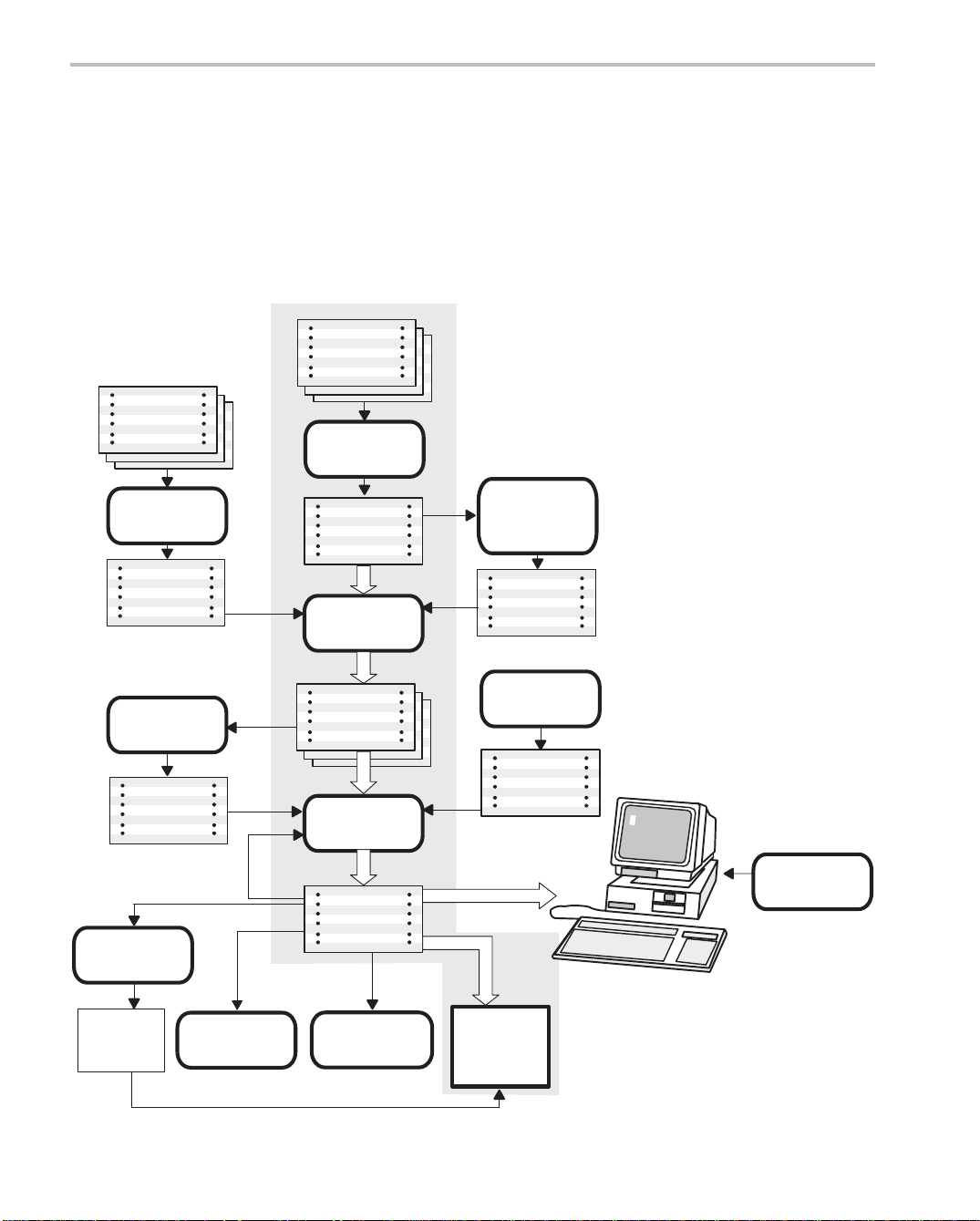
Figure 1–1 illustrates the ’C54x software development flow. The shaded
portion of the figure highlights the most common path of software development; the other portions are optional.
Figure 1–1. TMS320C54x Software Development Flow
C
source
files
Macro
source
files
Archiver
C compiler
Assembler
source
Assembly
translation
assistant
Macro
library
Archiver
Library of
object
files
Hex conversion
utility
EPROM
programmer
Absolute lister
Assembler
COFF
object
files
Linker
Executable
COFF
file
Cross-reference
lister
Assembler
source
Library-build
utility
Runtime-
support
library
Debugging
tools
’C54x
1-2
Page 25
1.2 Tools Descriptions
The following list describes the tools that are shown in Figure 1–1:
-
The C compiler translates C source code into ’C54x assembly language
source code. The compiler package includes the library-build utility , with
which you can build your own runtime libraries. The C compiler is not
shipped with the assembly language tools package.
-
The assembler translates assembly language source files into machine
language COFF object files. Source files can contain instructions, assembler directives, and macro directives. Y ou can use assembler directives to
control various aspects of the assembly process, such as the source listing format, data alignment, and section content.
-
The linker combines relocatable COFF object files (created by the assembler) into a single executable COFF object module. As it creates the
executable module, it adjusts references to symbols and resolves external
references. It also accepts archiver library members and output modules
created by a previous linker run. Linker directives allow you to combine object file sections, bind sections or symbols to addresses or within memory
ranges, and define or redefine global symbols.
Tools Descriptions
-
The archiver collects a group of files into a single archive file. For exam-
ple, you can collect several macros into a macro library. The assembler
searches the library and uses the members that are called as macros by
the source file. You can also use the archiver to collect a group of object
files into an object library. The linker includes in the library the members
that resolve external references during the link.
-
The mnemonic-to-algebraic assembly translator utility converts an
assembly language source file containing mnemonic instructions to an
assembly language source file containing algebraic instructions.
-
The library-build utility builds your own customized, C, runtime-support
library . Standard runtime-support library functions are provided as source
code in rts.src and as object code in rts.lib.
-
The TMS320C54x DSP accepts COFF files as input, but most EPROM
programmers do not. The hex conversion utility converts a COFF object
file into TI-tagged, Intel, Motorola, or Tektronix object format. The
converted file can be downloaded to an EPROM programmer.
Introduction
1-3
Page 26
Tools Descriptions
-
The absolute lister accepts linked object files as input and creates .abs
files as output. You assemble .abs files to produce a listing that contains
absolute rather than relative addresses. Without the absolute lister,
producing such a listing would be tedious and require many manual operations.
-
The cross-reference lister uses object files to produce a cross-reference
listing showing symbols, their definitions, and their references in the linked
source files.
The purpose of this development process is to produce a module that can be
executed in a ’C54x target system. Y ou can use one of several debugging tools
to refine and correct your code. Available products include:
-
An instruction-accurate software simulator
-
An extended development system (XDS510) emulator
-
An evaluation module (EVM)
For information about these debugging tools, see the
Debugger User’s Guide
.
TMS320C54x C Source
1-4
Page 27

Chapter 2
Introduction to Common Object File Format
The assembler and linker create object files that can be executed by a
TMS320C54x device. The format for these object files is called common object
file format (COFF).
COFF makes modular programming easier, because it encourages you to
think in terms of blocks of code and data when you write an assembly language
program. These blocks are known as
linker provide directives that allow you to create and manipulate sections.
This chapter provides an overview of COFF sections. For additional
information, see Appendix A,
COFF structure.
Common Object File Format
sections
. Both the assembler and the
, which explains the
Topic Page
2.1 COFF File Types 2-2. . . . . . . . . . . . . . . . . . . . . . . . . . . . . . . . . . . . . . . . . . . . . .
2.2 Sections 2-2. . . . . . . . . . . . . . . . . . . . . . . . . . . . . . . . . . . . . . . . . . . . . . . . . . . . .
2.3 How the Assembler Handles Sections 2-4. . . . . . . . . . . . . . . . . . . . . . . . . .
2.4 How the Linker Handles Sections 2-12. . . . . . . . . . . . . . . . . . . . . . . . . . . . .
2.5 Relocation 2-15. . . . . . . . . . . . . . . . . . . . . . . . . . . . . . . . . . . . . . . . . . . . . . . . . . .
2.6 Runtime Relocation 2-17. . . . . . . . . . . . . . . . . . . . . . . . . . . . . . . . . . . . . . . . . .
2.7 Loading a Program 2-18. . . . . . . . . . . . . . . . . . . . . . . . . . . . . . . . . . . . . . . . . . .
2.8 Symbols in a COFF File 2-19. . . . . . . . . . . . . . . . . . . . . . . . . . . . . . . . . . . . . . .
Introduction to Common Object File Format
2-1
Page 28
COFF File Types
COFF File Types /Sections
2.1 COFF File Types
The following types of COFF files exist:
-
-
-
Each COFF file type has a different header format. The data portions of the
COFF files are identical. For details about the COFF file structure, see
Appendix A,
The TMS320C54x assembler and C compiler create COFF2 files. The linker
can read and write all types of COFF files. By default, the linker creates COFF2
files. Use the –v linker option to specify a different format. The linker supports
COFF0 and COFF1 files for older versions of the assembler and C compiler
only.
COFF0
COFF1
COFF2
Common Object File Format
.
2.2 Sections
The smallest unit of an object file is called a
section
. A section is a block of code
or data that will ultimately occupy contiguous space in the memory map. Each
section of an object file is separate and distinct. COFF object files always contain three default sections:
.text section usually contains executable code
.data section usually contains initialized data
.bss section usually reserves space for uninitialized variables
In addition, the assembler and linker allow you to create, name, and link
named
sections that are used like the .data, .text, and .bss sections.
There are two basic types of sections:
initialized sections contain data or code. The .text and .data sections
are initialized; named sections created with the
.sect assembler directive are also initialized.
uninitialized sections reserve space in the memory map for uninitialized
data. The .bss section is uninitialized; named
sections created with the .usect assembler directive are also uninitialized.
2-2
Page 29
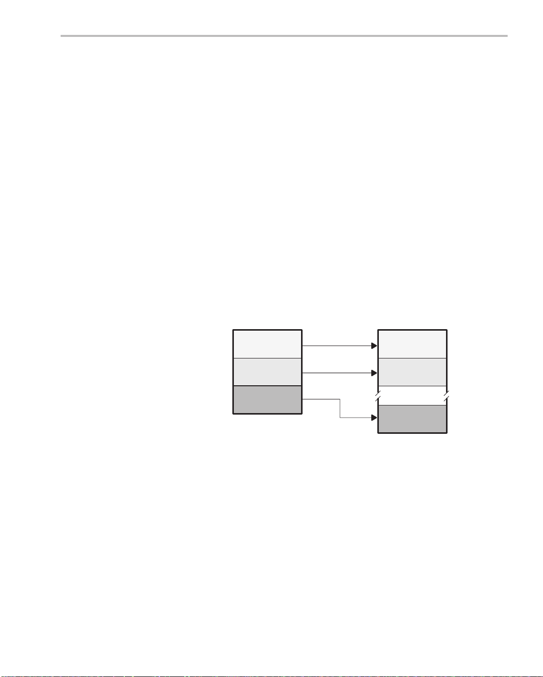
Several assembler directives allow you to associate various portions of code
and data with the appropriate sections. The assembler builds these sections
during the assembly process, creating an object file organized as shown in
Figure 2–1.
One of the linker’s functions is to relocate sections into the target memory map;
this function is called
allocation
. Because most systems contain several types
of memory, using sections can help you use target memory more efficiently.
All sections are independently relocatable; you can place any section into any
allocated block of target memory . For example, you can define a section that
contains an initialization routine and then allocate the routine into a portion of
the memory map that contains ROM.
Figure 2–1 shows the relationship between sections in an object file and a
hypothetical target memory.
Figure 2–1. Partitioning Memory Into Logical Blocks
Sections
Object File
.bss
.data
.text
Target Memory
RAM
EEPROM
ROM
Introduction to Common Object File Format
2-3
Page 30
How the Assembler Handles Sections
2.3 How the Assembler Handles Sections
The assembler identifies the portions of an assembly language program that
belong in a section. The assembler has five directives that support this
function:
-
.bss
-
.usect
-
.text
-
.data
-
.sect
The .bss and .usect directives create
and .sect directives create
You can create subsections of any section to give you tighter control of the
memory map. Subsections are created using the .sect and .usect directives.
Subsections are identified with the base section name and a subsection name
separated by a colon. See subsection 2.3.4,
information.
Note: Default Section Directive
If you don’t use any of the sections directives, the assembler assembles
everything into the .text section.
2.3.1 Uninitialized Sections
Uninitialized sections reserve space in processor memory; they are usually
allocated into RAM. These sections have no actual contents in the object file;
they simply reserve memory. A program can use this space at runtime for
creating and storing variables.
Uninitialized data areas are built by using the .bss and .usect assembler
directives.
uninitialized sections
initialized sections
.
Subsections
; the .text, .data,
, page 2-8, for more
2-4
-
The .bss directive reserves space in the .bss section.
-
The .usect directive reserves space in a specific, uninitialized named
section.
Each time you invoke the .bss directive, the assembler reserves more space
in the appropriate section. Each time you invoke the .usect directive, the
assembler reserves more space in the specified named section.
Page 31

The syntax for these directives is:
.bss
symbol, size in words [, [blocking flag]
symbol
.usect ”
section name ”, size in words
How the Assembler Handles Sections
[,
alignment flag
[, [
blocking flag]
]]
[,
alignment flag
]]
symbol
size in words
blocking flag
alignment flag
section name
points to the first word reserved by this invocation of the .bss
or .usect directive. The
symbol
corresponds to the name of
the variable that you’re reserving space for. It can be referenced by any other section and can also be declared as a
global symbol (with the .global assembler directive).
is an absolute expression.
-
The .bss directive reserves
size
words in the .bss sec-
tion.
-
The .usect directive reserves
size
words in
section
name.
is an optional parameter. If you specify a value greater than
0 for this parameter, the assembler associates size words
contiguously; the allocated space will not cross a page
boundary , unless size is greater than a page, in which case
the object will start on a page boundary.
is an optional parameter. If you specify a value greater than
0 for this parameter, the section is aligned to a long
word
boundary.
tells the assembler which named section to reserve space
in. For more information about named sections, see
subsection 2.3.3,
Named Sections
, on page 2-7.
The .text, .data, and .sect directives tell the assembler to stop assembling into
the current section and begin assembling into the indicated section. The .bss
and .usect directives, however,
do not
end the current section and begin a new
one; they simply escape temporarily from the current section. The .bss and
.usect directives can appear anywhere in an initialized section without
affecting its contents.
Uninitialized subsections are created with the .usect directive. The assembler
treats uninitialized subsections in the same manner as uninitialized sections.
See subsection 2.3.4,
Subsections
, on page 2-8 for more information on
creating subsections.
Introduction to Common Object File Format
2-5
Page 32

How the Assembler Handles Sections
2.3.2 Initialized Sections
Initialized sections contain executable code or initialized data. The contents
of these sections are stored in the object file and placed in processor memory
when the program is loaded. Each initialized section is independently relocatable and may reference symbols that are defined in other sections. The linker
automatically resolves these section-relative references.
Three directives tell the assembler to place code or data into a section. The
syntaxes for these directives are:
.text [
value
.data [
value
.sect ”
When the assembler encounters one of these directives, it stops assembling
into the current section (acting as an implied end-current-section command).
It then assembles subsequent code into the designated section until it encounters another .text, .data, or .sect directive. The
starting value of the section program counter. The starting value of the section
program counter can be specified only once; it must be done the first time the
directive for that section is encountered. By default, the SPC starts at 0.
section name
]
]
” [,
value
]
value
, if present, specifies the
2-6
Sections are built through an iterative process. For example, when the assembler first
encounters a .data directive, the .data section is empty. The statements following this first .data directive are assembled into the .data section
(until the assembler encounters a .text or .sect directive). If the assembler
encounters subsequent .data directives, it adds the statements following
these .data directives to the statements already in the .data section. This
creates a single .data section that can be allocated contiguously into memory .
Initialized subsections are created with the .sect directive. The assembler
treats initialized subsections in the same manner as initialized sections. See
subsection 2.3.4,
Subsections
, on page 2-8 for more information on creating
subsections.
Page 33

2.3.3 Named Sections
How the Assembler Handles Sections
Named sections are sections that
you
create. Y ou can use them like the default
.text, .data, and .bss sections, but they are assembled separately.
For example, repeated use of the .text directive builds up a single .text section
in the object file. When linked, this .text section is allocated into memory as a
single unit. Suppose there is a portion of executable code (perhaps an initialization routine) that you don’t want allocated with .text. If you assemble this
segment of code into a named section, it is assembled separately from .text,
and you can allocate it into memory separately . Y ou can also assemble initialized data that is separate from the .data section, and you can reserve space
for uninitialized variables that is separate from the .bss section.
Two directives let you create named sections:
-
The .usect directive creates sections that are used like the .bss section.
These sections reserve space in RAM for variables.
-
The .sect directive creates sections, like the default .text and .data
sections, that can contain code or data. The .sect directive creates named
sections with relocatable addresses.
The syntax for these directives is shown below:
symbol
.usect ”
.sect ”
section name”, size in words
section name
”
[, [
blocking flag
] [,
alignment flag
]]
The
section name
parameter is the name of the section. Y ou can create up to
32 767 separate named sections. A section name can be up to 200 characters.
For COFF1 files, only the first 8 characters are significant. For the .sect and
.usect directives, a section name can refer to a subsection (see subsection
2.3.4,
Subsections
, for details).
Each time you invoke one of these directives with a new name, you create a
new named section. Each time you invoke one of these directives with a name
that was already used, the assembler assembles code or data (or reserves
space) into the section with that name.
different directives
. That is, you cannot create a section with the .usect direc-
You cannot use the same names with
tive and then try to use the same section with .sect.
Introduction to Common Object File Format
2-7
Page 34

How the Assembler Handles Sections
2.3.4 Subsections
Subsections are smaller sections within larger sections. Like sections,
subsections can be manipulated by the linker. Subsections give you tighter
control of the memory map. Y ou can create subsections by using the .sect or
.usect directive. The syntax for a subsection name is:
section name:subsection name
A subsection is identified by the base section name followed by a colon, then
the name of the subsection. A subsection can be allocated separately or
grouped with other sections using the same base name. For example, to
create a subsection called _func within the .text section, enter the following:
.sect ”.text:_func”
You can allocate _func separately or within all the .text sections.
You can create two types of subsections:
-
Initialized subsections are created using the .sect directive. See
subsection 2.3.2,
Initialized Sections
, on page 2-6.
-
Uninitialized subsections are created using the .usect directive. See
subsection 2.3.1,
Subsections are allocated in the same manner as sections. See Section 7.8,
The SECTIONS Directive
2.3.5 Section Program Counters
The assembler maintains a separate program counter for each section. These
program counters are known as
An SPC represents the current address within a section of code or data.
Initially , the assembler sets each SPC to 0. As the assembler fills a section with
code or data, it increments the appropriate SPC. If you resume assembling into
a section, the assembler remembers the appropriate SPC’s previous value
and continues incrementing the SPC at that point.
The assembler treats each section as if it began at address 0; the linker
relocates each section according to its final location in the memory map. For
more information, see Section 2.5,
Uninitialized Sections
, on page 2-4.
, on page 7-32 for more information.
section program counters
Relocation
, on page 2-15.
, or SPCs.
2-8
Page 35

2.3.6 An Example That Uses Sections Directives
Example 2–1 shows how you can build COFF sections incrementally, using
the sections directives to swap back and forth between the different sections.
Y ou can use sections directives to begin assembling into a section for the first
time, or to continue assembling into a section that already contains code. In
the latter case, the assembler simply appends the new code to the code that
is already in the section.
The format in Example 2–1 is a listing file. Example 2–1 shows how the SPCs
are modified during assembly. A line in a listing file has four fields:
Field 1 contains the source code line counter.
Field 2 contains the section program counter.
Field 3 contains the object code.
Field 4 contains the original source statement.
How the Assembler Handles Sections
Introduction to Common Object File Format
2-9
Page 36

How the Assembler Handles Sections
Example 2–1. Using Sections Directives
2 ************************************************
3 ** Assemble an initialized table into .data. **
4 ************************************************
5 000000 .data
6 000000 0011 coeff .word 011h,022h,033h
000001 0022
000002 0033
7 ************************************************
8 ** Reserve space in .bss for a variable. **
9 ************************************************
10 000000 .bss buffer,10
11 ************************************************
12 ** Still in .data. **
13 ************************************************
14 000003 0123 ptr .word 0123h
15 ************************************************
16 ** Assemble code into the .text section. **
17 ************************************************
18 000000 .text
19 000000 100f add: LD 0Fh,A
20 000001 f010 aloop: SUB #1,A
000002 0001
21 000003 f842 BC aloop,AGEQ
000004 0001’
22 ************************************************
23 ** Another initialized table into .data. **
24 ************************************************
25 000004 .data
26 000004 00aa ivals .word 0AAh, 0BBh, 0CCh
000005 00bb
000006 00cc
27 ************************************************
28 ** Define another section for more variables. **
29 ************************************************
30 000000 var2 .usect ”newvars”, 1
31 000001 inbuf .usect ”newvars”, 7
32 ************************************************
33 ** Assemble more code into .text. **
34 ************************************************
35 000005 .text
36 000005 110a mpy: LD 0Ah,B
37 000006 f166 mloop: MPY #0Ah,B
000007 000a
38 000008 f868 BC mloop,BNOV
000009 0006’
39 ************************************************
40 ** Define a named section for int. vectors. **
41 ************************************************
42 000000 .sect ”vectors”
43 000000 0011 .word 011h, 033h
44 000001 0033
2-10
Field 2Field 1 Field 3 Field 4
Page 37

How the Assembler Handles Sections
As Figure 2–2 shows, the file in Example 2–1 creates five sections:
.text contains ten 16-bit words of object code.
.data contains seven words of object code.
vectors is a named section created with the .sect directive; it contains
two words of initialized data.
.bss reserves 10 words in memory.
newvars is a named section created with the .usect directive; it reserves
eight words in memory.
The second column shows the object code that is assembled into these
sections; the first column shows the line numbers of the source statements that
generated the object code.
Figure 2–2. Object Code Generated by the File in Example 2–1
100f
f010
0001
f842
0001’
110a
f166
000a
f868
0006’
43
44
Introduction to Common Object File Format
2-11
Page 38

Page 39

Page 40

Page 41

Page 42

Page 43

Page 44

Page 45

Page 46

Page 47

Page 48

Page 49

Page 50

Page 51

Page 52

Page 53

Page 54

Page 55

Page 56

Page 57

Page 58

Page 59

Page 60

Page 61

Page 62

Page 63

3.7 Character Strings
Character Strings
Character Strings
A character string is a string of characters enclosed in
double
quotes. Double
quotes that are part of character strings are represented by two consecutive
double quotes. The maximum length of a string varies and is defined for each
directive that requires a character string. Characters are represented
internally as 8-bit ASCII characters.
These are examples of valid character strings:
”sample program” defines the 14-character string
”PLAN ””C””” defines the 8-character string
sample program.
PLAN ”C”.
Character strings are used for the following:
-
Filenames, as in .copy ”filename”
-
Section names, as in .sect ”section name”
-
Data initialization directives, as in .byte ”charstring”
-
Operands of .string directives
Assembler Description
3-17
Page 64

Symbols
3.8 Symbols
3.8.1 Labels
Symbols are used as labels, constants, and substitution symbols. A symbol
name is a string of up to 200 alphanumeric characters (A –Z, a–z, 0–9, $,
and _). The first character in a symbol cannot be a number, and symbols cannot contain embedded blanks. The symbols you define are case sensitive; for
example, the assembler recognizes ABC, Abc, and abc as three unique
symbols. You can override case sensitivity with the – c assembler option. A
symbol is valid only during the assembly in which it is defined, unless you use
the .global directive to declare it as an external symbol.
Symbols used as labels become symbolic addresses associated with locations in the program. Labels used locally within a file must be unique.
Mnemonic opcodes and assembler directive names (without the ”.” prefix) are
valid label names.
Labels can also be used as the operands of .global, .ref, .def, or .bss directives;
for example:
.global label1
label2 NOP
3.8.2 Symbolic Constants
Symbols can be set to constant values. By using constants, you can equate
meaningful names with constant values. The .set and .struct/.tag/.endstruct
directives enable you to set constants to symbolic names. Symbolic constants
cannot
be used:
K .set 1024 ;constant definitions
maxbuf .set 2*K
value .set 0.
delta .set 1.
item .struct ;item structure definition
i_len .endstruct
array .tag item ;array declaration
The assembler also has several predefined symbolic constants; these are
discussed in the next section.
ADD label1,B
B label2
be redefined. The following example shows how these directives can
.int value ;constant offsets value = 0
.int delta ;constant offsets delta = 1
.bss array, i_len*K
3-18
Page 65

3.8.3 Defining Symbolic Constants (–d Option)
The –d option equates a constant value with a symbol. The symbol can then
be used in place of a value in assembly source. The format of the –d option
is as follows:
Symbols
asm500 –d
The
name
name=[value
is the name of the symbol you want to define. The
you want to assign to the symbol. If the
Within assembler source, you may test the symbol with the following direc-
tives:
Type of Test Directive Usage
Existence .if $isdefed(”
Nonexistence .if $isdefed(”
Equal to value .if
Not equal to value .if
Note that the argument to the $isdefed built-in function must be enclosed in
quotes. The quotes cause the argument to be interpreted literally rather than
as a substitution symbol.
3.8.4 Predefined Symbolic Constants
The assembler has several predefined symbols, including the following:
]
value
is the value
value
is omitted, the symbol is set to 1.
name
”)
name
”) = 0
name
=
value
name
!=
value
-
$, the dollar sign character, represents the current value of the section
program counter (SPC).
-
Register symbols, including AR0 – AR7
-
Symbols that are defined by using the .mmregs directive (see Table 4–2
on page 4-70 for a list of registers)
Assembler Description
3-19
Page 66

Symbols
3.8.5 Substitution Symbols
Symbols can be assigned a string value (variable). This enables you to alias
character strings by equating them to symbolic names. Symbols that
represent character strings are called substitution symbols. When the
assembler encounters a substitution symbol, its string value is substituted for
the symbol name. Unlike symbolic constants, substitution symbols can be
redefined.
A string can be assigned to a substitution symbol anywhere within a program;
for example:
.asg ”errct”, AR2 ;register 2
.asg ”*+”, INC ;indirect auto-increment
.asg ”*–”, DEC ;indirect auto-decrement
When you are using macros, substitution symbols are important because
macro parameters are actually substitution symbols that are assigned a macro
argument. The following code shows how substitution symbols are used in
macros:
add2 .macro ADDRA,ADDRB ;add2 macro definition
LD ADDRA, A
ADD ADDRB, A
STL A, ADDRB
.endm
; add2 invocation
add2 LOC1, LOC2 ;add ”LOC1” argument to a
;second argument ”LOC2”.
; instructions for expanded macro:
; LD LOC1, A
; ADD LOC2, A
; STL A, LOC2
For more information about macros, see Chapter 5,
Macro Language
.
3-20
Page 67

3.8.6 Local Labels
Symbols
Local labels are special labels whose scope and effect are temporary . A local
label can be defined in two ways:
-
$n, where n is a decimal digit in the range of 0–9. For example, $4 and $1
are valid local labels.
-
NAME?, where NAME is any legal symbol name as described above. The
assembler replaces the question mark with a period followed by a unique
number. When the source code is expanded, you will not see the unique
number in the listing file. Your label appears with the question mark as it
did in the macro definition. You cannot declare this label as global.
Normal labels must be unique (they can be declared only once), and they can
be used as constants in the operand field. Local labels, however, can be
undefined and defined again or automatically generated. Local labels cannot
be defined by directives.
A local label can be undefined, or reset, in one of four ways:
-
By using the .newblock directive
-
By changing sections (using a .sect, .text, or .data directive)
-
By entering an include file (specifying the .include or .copy directive)
-
By leaving an include file (specifying the .include or .copy directive)
Example 3–1 demonstrates the $n form. This example assumes that symbols
ADDRA, ADDRB, ADDRC have been defined previously.
Example 3–1. $n Local Labels
(a) Code that uses a local label legally
Label1: LD ADDRA, A ; Load Address A to Accumulator A.
$1 LD ADDRA, A ; $1: load ADDRA to Accumulator A.
$2 ADD ADDRC, A ; $2: add ADDRC.
$1 NOP
SUB ADDRB, A ; Subtract Address B.
BC $1, ALT ; If less than zero, branch to $1;
LD ADDRB, A ; otherwise, load ADDRB to A
B $2 ; and branch to $2.
.newblock ; Undefine $1 so it can be used
; again.
BC $1, ALT ; If less than zero, branch to $1.
STL A, ADDRC ; Store ACC low in ADDRC.
Assembler Description
3-21
Page 68

Symbols
(b) Code that uses a local label illegally
Label1: LD ADDRA, A ; Load Address A to Accumulator A.
$1 LD ADDRA, A ; $1: Load ADDRA To Accumulator A.
$2 ADD ADDRC, A ; $2: Add ADDRC.
$1 NOP ; WRONG: $1 is multiply defined.
SUB ADDRB, A ; Subtract Address B.
BC $1, ALT ; If less than zero, branch to $1;
LD ADDRB, A ; otherwise, load ADDRB To A
B $2 ; and Branch to $2.
BC $1, ALT ; If less than 0, branch to $1.
STL A, ADDRC ; Store Acc low in ADDRC.
Local labels are especially useful in macros. If a macro contains a normal label
and is called more than once, the assembler issues a multiple-definition error.
If you use a local label and .newblock within a macro, however, the local label
is used and reset each time the macro is expanded.
Up to ten local labels can be in effect at one time. After you undefine a local
label, you can define it and use it again. Local labels do not appear in the object
code symbol table.
The maximum label length is shortened to allow for the unique suffix. If the
macro is expanded fewer than 10 times, the maximum label length is 126 characters. If the macro is expanded from 10 to 99 times, the maximum label length
is 125.
3-22
name
Example 3–2 demonstrates the
? form.
Page 69

Example 3–2. name? Local Labels
;*********************************************************
; First definition of local label ’mylab’
;*********************************************************
nop
mylab? nop
b mylab?
;*********************************************************
; Include file has second definition of ’mylab’
;*********************************************************
.copy ”a.inc”
;*********************************************************
;Third definition of ’mylab’, reset upon exit from include
;*********************************************************
mylab? nop
b mylab?
;*********************************************************
; Fourth definition of ’mylab’ in macro, macros use
; different namespace to avoid conflicts
;*********************************************************
mymac .macro
mylab? nop
b mylab?
.endm
;*********************************************************
; Macro invocation
;*********************************************************
mymac
;*********************************************************
; Reference to third definition of ’mylab’, note that
; definition is not reset by macro invocation nor
; conflicts with same name defined in macro
;*********************************************************
b mylab?;
*********************************************************
; Changing section, allowing fifth definition of ’mylab’
;*********************************************************
.sect ”Secto_One”
nop
mylab? .word 0
nop
nop
b mylab?
;*********************************************************
;.newblock directive, allowing sixth definition of ’mylab’
;*********************************************************
.newblock
mylab? .word 0
nop
nop
b mylab?
Symbols
Assembler Description
3-23
Page 70

Expressions
3.9 Expressions
An expression is a constant, a symbol, or a series of constants and symbols
separated by arithmetic operators. The range of valid expression values is
–32 768 to 32 767. Three main factors influence the order of expression evaluation:
Parentheses Expressions that are enclosed in parentheses are
always evaluated first.
8 / (4 / 2) = 4, but 8 / 4 / 2 = 1
cannot
You
substitute braces ( { } ) or brackets ( [ ] )
for parentheses.
Precedence groups The ’C54x assembler uses the same order of pre-
cedence as the C language does as summarized
in Table 3–1. This differs from the order of precedence of other TMS320 assemblers. When parentheses do not determine the order of expression
evaluation, the highest precedence operation is
evaluated first.
8 + 4 / 2 = 10 (4 / 2 is evaluated first)
Left-to-right evaluation When parentheses and precedence groups do not
determine the order of expression evaluation, the
expressions are evaluated as happens in the C
language.
8 / 4*2 = 4 , but 8 / (4*2) = 1
3-24
Page 71

3.9.1 Operators
Table 3–1 lists the operators that can be used in expressions.
Note: Differences in Precedence From Other TMS320 Assemblers
Some other TMS320 processors use a different order of precedence than
the TMS320C54x, and occasionally different results may be produced from
the same source code for this reason. The ’C54x uses the same order of precedence as the C language.
Table 3–1. Operators Used in Expressions (Precedence)
Symbols Operators Evaluation
+ – ~ Unary plus, minus, 1s complement Right to left
* / % Multiplication, division, modulo Left to right
+ – Addition, subtraction Left to right
<< >> Left shift, right shift Left to right
Expressions
< <= > >= Less than, LT or equal, greater than,
GT or equal
!=, =[=] Not equal to, equal to Left to right
& Bitwise AND Left to right
^ Bitwise exclusive OR Left to right
| Bitwise OR Left to right
Note: Unary +, –, and * have higher precedence than the binary forms.
3.9.2 Expression Overflow and Underflow
The assembler checks for overflow and underflow conditions when arithmetic
operations are performed at assembly time. It issues a V alue Truncated warn-
ing whenever an overflow or underflow occurs. The assembler
for overflow or underflow in multiplication.
Left to right
does not
check
Assembler Description
3-25
Page 72

Expressions
3.9.3 Well-Defined Expressions
Some assembler directives require well-defined expressions as operands.
Well-defined expressions contain only symbols or assembly-time constants
that are defined before they are encountered in the expression. The evaluation
of a well-defined expression must be absolute.
Example 3–3. Well-Defined Expressions
(a) Valid well-defined expressions
label1 .word 0
label2 .word 3
X .set 50h
goodsym1 .set 100h + X : Because value of X is defined before
goodsym2 .set $ ; All references to previously defined local
goodsym3 .set label1 : labels, including the current SPC ($), are
goodsym4 .set label2 – label1 ; Although label1 and label2 are not
(b) Invalid well-defined expressions
.data
.word 1
.word 2
; referenced, this is a valid well-defined
; expression
; considered to be well-defined.
; absolute symbols, because they are local
; labels defined in the same section, their
; difference can be computed by the assembler.
; The difference is absolute, so the
; expression is well-defined.
.global Y
badsym1 .set Y ; Because Y is external and is not defined in
badsym2 .set 50h + Y ; the current file, its value is unknown to
badsym3 .set 50h + Z ; Although Z is defined in the current file,
Z .set 60h ; its definition appears after the expression
3-26
; the assembler. Therefore, it cannot be used
; where a well-defined expression is needed.
; in which it is used. All symbols and
; constants that appear in well-defined
; expressions must be defined before they are
; referenced.
Page 73

3.9.4 Conditional Expressions
The assembler supports relational operators that can be used in any
expression; they are especially useful for conditional assembly. Relational
operators include the following:
= Equal to = = Equal to
! = Not equal to
< Less than <= Less than or equal to
> Greater than > = Greater than or equal to
Conditional expressions evaluate to 1 if true and 0 if false; they can be used
only on operands of equivalent types, for example, absolute value compared
to absolute value, but not absolute value compared to relocatable value.
3.9.5 Relocatable Symbols and Legal Expressions
T able 3–2 summarizes valid operations on absolute, relocatable, and external
symbols. An expression cannot contain multiplication or division by a relocatable or external symbol. An expression cannot contain unresolved symbols
that are relocatable to other sections.
Expressions
Symbols or registers that have been defined as global with the .global directive
can also be used in expressions; in T able 3–2, these symbols and registers are
referred to as
external
.
Relocatable registers can be used in expressions; the addresses of these
registers are relocatable with respect to the register section they were defined
in, unless they have been declared as external.
Table 3–2. Expressions With Absolute and Relocatable Symbols
If A is... and If B is... , then A + B is... and A – B is...
absolute absolute absolute absolute
absolute external external illegal
absolute relocatable relocatable illegal
relocatable absolute relocatable relocatable
relocatable relocatable illegal absolute
relocatable external illegal illegal
external absolute external external
external relocatable illegal illegal
external external illegal illegal
†
A and B must be in the same section; otherwise, this is illegal.
†
Assembler Description
3-27
Page 74

Expressions
Following are examples of expressions that use relocatable and absolute symbols. These examples use four symbols that are defined in the same section:
.global extern_1 ; Defined in an external module
intern_1: .word ’”D’ ; Relocatable, defined in current module
LAB1: .set 2 ; LAB1 = 2
intern_2 ; Relocatable, defined in current module
Example 1
-
The statements in this example use an absolute symbol, LAB1 (which is
defined above to have a value of 2). The first statement loads the value 51
into the accumulator:
LD #LAB1 + ((4+3) * 7), A ; ACC A = 51
LD #LAB1 + 4 + (3*7), A ; ACC A = 27
-
Example 2
All legal expressions can be reduced to one of two forms:
relocatable symbol ± absolute symbol
or
absolute value
Unary operators can be applied only to absolute values; they cannot be
applied to relocatable symbols. Expressions that cannot be reduced to
contain only one relocatable symbol are illegal. The first statement in the
following example is valid; the statements that follow it are invalid.
LD extern_1 – 10, B ; Legal
LD 10–extern_1, B ; Can’t negate reloc. symbol
LD –(intern_1), B ; Can’t negate reloc. symbol
LD extern_1/10, B ; / isn’t additive operator
LD intern_1 + extern_1, B ; Multiple relocatables
-
Example 3
The first statement below is legal; although intern_1 and intern_2 are
relocatable, their difference is absolute because they’re in the same
section. Subtracting one relocatable symbol from another reduces the
expression to
relocatable symbol + absolute value
. The second statement
is illegal because the sum of two relocatable symbols is not an absolute
value.
LD intern_1 – intern_2 + extern_1, B ; Legal
LD intern_1 + intern_2 + extern_1, B ; Illegal
-
Example 4
An external symbol’s placement is important to expression evaluation.
Although the statement below is similar to the first statement in the
previous example, it is illegal because of left-to-right operator precedence;
the assembler attempts to add intern_1 to extern_1.
LD intern_1 + extern_1 – intern_2, B ; Illegal
3-28
Page 75

3.10 Built-in Functions
The assembler supports built-in functions for conversions and transcendental
math computations. Table 3–3 describes the built-in functions. Note that
must be a constant value. See Table 5–1 for a description of the assembler’s
non-mathematical built-in functions.
Table 3–3. Assembler Built-In Math Functions
Function Description
$acos(
expr
) returns the arc cosine of
$asin(
expr
) returns the arc sine of
$atan(
expr
) returns the arc tangent of
expr
$atan2(
$ceil(
) returns the arc tangent of
(–pi to pi)
expr
) returns the smallest integer that is not less than the
expression
expr
as a floating-point value
expr
as a floating-point value
expr
as a floating-point value
expr
as a floating-point value
Built-in Functions
expr
$cosh(
$cos(
expr
$cvf(
expr
$cvi(
expr
expr
$exp(
$fabs(
$floor(
$fmod(
$int(
expr
$ldexp(
$log10(
$log(
expr
$max(
$min(
expr1, expr2
expr
) returns the hyperbolic cosine of
value
) returns the cosine of
) converts
) converts
) returns the result of raising e to the
expr
) returns absolute value of
expr
) returns the largest integer that is not greater than the
expression
expr1, expr2
) returns 1 if
expr1, expr2
) returns the remainder after dividing
) returns the result of
expr2
expr
) returns the base 10 logarithm of
) returns the natural logarithm of
expr1, expr2
) returns the maximum of 2 expressions
) returns the minimum of 2 expressions
expr
expr
expr
power
expr
to floating-point value
to integer value
has an integer result
expr1
expr
as a floating-point
as a floating-point value
expr
power
expr
as a floating-point value
expr1
multiplied by 2 raised to the
expr
expr
and
expr2
Assembler Description
3-29
Page 76

Extended Addressing Support
Built-in Functions / Extended Addressing Support
Table 3–3. Assembler Built-In Math Functions (Continued)
Function Description
$pow(
expr1, expr2
) raises
expr1
to the power
expr
2
$round(
$sgn(
$sin(
$sinh(
$sqrt(
$tan(
$tanh(
$trunc(
expr
) returns the result of
expr
) returns the sign of
expr
) returns the sine of
expr
) returns the hyperbolic sine of
expr
) returns the square root of
expr
) returns the tangent of
expr
) returns the hyperbolic tangent of
expr
) returns the result of
3.11 Extended Addressing Support
The assembler accepts a pseudo-op, LDX, for loading the value of a label,
function, etc. that resides (or may reside) in extended program memory . LDX
is used to load the upper 8 bits of a 24-bit address.
For example, if a function, F1, is in extended program memory (which is 24 bits
instead of 16), the value or address of F1 may be loaded as follows:
value
value
expr
rounded to the nearest integer
expr
expr
as a floating-point value
expr
as a floating-point
expr
as a floating-point value
expr
as a floating-point value
expr
as a floating-point
expr
rounded toward zero
3-30
LDX #F1,16,A ;loads the upper 8 bits of the 24-bit
;address of F1
OR #F1,A,A ;adds in the lower 16 bits of the
;address of F1
BACC A ;all 24 bits of F1 have been loaded
;into accumulator A
Note that it is necessary to use both LDX and OR to load the entire 24-bit
address.
Page 77

3.12 Source Listings
A source listing shows source statements and the object code they produce.
To obtain a listing file, invoke the assembler with the –l (lowercase L) option.
Two banner lines, a blank line, and a title line are at the top of each source listing page. Any title supplied by a .title directive is printed on the title line; a page
number is printed to the right of the title. If you don’t use the .title directive, the
name of the source file is printed. The assembler inserts a blank line below the
title line.
Each line in the source file may produce a line in the listing file that shows a
source statement number, an SPC value, the object code assembled, and the
source statement. A source statement may produce more than one word of
object code. The assembler lists the SPC value and object code on a separate
line for each additional word. Each additional line is listed immediately
following the source statement line.
Field 1: Source Statement Number
Source Listings
Line Number
The source statement number is a decimal. The assembler numbers
source lines as it encounters them in the source file; some statements increment the line counter but are not listed. (For example,
.title statements and statements following a .nolist are not listed.)
The difference between two consecutive source line numbers indicates the number of intervening statements in the source file that are
not listed.
Include File Letter
The assembler may precede a line with a letter; the letter indicates
that the line is assembled from an included file.
Nesting Level Number
The assembler may precede a line with a number; the number indicates the nesting level of macro expansions or loop blocks.
Field 2: Section Program Counter
This field contains the section program counter (SPC) value, which
is hexadecimal. All sections (.text, .data, .bss, and named sections)
maintain separate SPCs. Some directives do not affect the SPC and
leave this field blank.
Assembler Description
3-31
Page 78

Source Listings
Field 3: Object Code
This field contains the hexadecimal representation of the object
code. All machine instructions and directives use this field to list
object code. This field also indicates the relocation type by appending one of the following characters to the end of the field:
! undefined external reference
’ .text relocatable
” .data relocatable
+ .sect relocatable
– .bss, .usect relocatable
Field 4: Source Statement Field
This field contains the characters of the source statement as they
were scanned by the assembler. The assembler accepts a maximum
line length of 200 characters. Spacing in this field is determined by
the spacing in the source statement.
Example 3–4 shows an assembler listing with each of the four fields identified.
3-32
Page 79

Example 3–4. Assembler Listing
(a) Mnemonic example
1 .global RESET, INT0, INT1, INT2
2 .global TINT, RINT, XINT, USER
3 .global ISR0, ISR1, ISR2
4 .global time, rcv, xmt, proc
5
6 initmac .macro
7 * initialize macro
8 SSBX OVM ; disable oflow
9 LD #0, DP ; dp = 0
10 LD #7, ARP ; arp = ar7
11 LD #037h, A ; acc = 03fh
12 RSBX INTM ; enable ints
13 .endm
14 *******************************************
15 * Reset and interrupt vectors *
16 *******************************************
17 000000 .sect ”reset”
18 000000 F073 RESET: B init
000001 0008+
19 000002 F073 INT0: B ISR0
000003 0000!
20 000004 F073 INT1: B ISR1
000005 0000!
21 000006 F073 INT2: B ISR2
000007 0000!
22
23 *
24 000000 .sect ”ints”
25 000000 F073 TINT B time
000001 0000!
26 000002 F073 RINT B rcv
000003 0000!
27 000004 F073 XINT B xmt
000005 0000!
28 000006 F073 USER B proc
000007 0000!
29 *******************************************
30 * Initialize processor. *
31 *******************************************
32 000008 init: initmac
1 * initialize macro
1 000008 F7B9 SSBX OVM ; disable oflow
1 000009 EA00 LD #0, DP ; dp = 0
1 00000a F4A7 LD #7, ARP ; arp = ar7
1 00000b E837 LD #037h, A ; acc = 03fh
1 00000c F6BB RSBX INTM ; enable ints
Source Listings
Field 1 Field 2 Field 3 Field 4
Assembler Description
3-33
Page 80

Source Listings
Example 3–4.Assembler Listing (Continued)
(b) Algebraic example
1 .global RESET, INT0, INT1, INT2
2 .global TINT, RINT, XINT, USER
3 .global ISR0, ISR1, ISR2
4 .global time, rcv, xmt, proc
5
6 initmac .macro
7 * initialize macro
8 OVM = 1 ; disable oflow
9 DP = #0 ; dp = 0
10 ARP = #7 ; arp = ar7
11 A = #037h ; acc = 03fh
12 INTM = 0 ; enable ints
13 .endm
14 *******************************************
15 * Reset and interrupt vectors *
16 *******************************************
17 000000 .sect ”reset”
18 000000 F073 RESET: goto init
000001 0008+
19 000002 F073 INT0: goto ISR0
000003 0000!
20 000004 F073 INT1: goto ISR1
000005 0000!
21 000006 F073 INT2: goto ISR2
000007 0000!
22
23 *
24 000000 .sect ”ints”
25 000000 F073 TINT goto time
000001 0000!
26 000002 F073 RINT goto rcv
000003 0000!
27 000004 F073 XINT goto xmt
000005 0000!
28 000006 F073 USER goto proc
000007 0000!
29 *******************************************
30 * Initialize processor. *
31 *******************************************
32 000008 init: initmac
1 * initialize macro
1 000008 F7B9 OVM = 1 ; disable oflow
1 000009 EA00 DP = #0 ; dp = 0
1 00000a F4A7 ARP = #7 ; arp = ar7
1 00000b E837 A = #037h ; acc = 03fh
1 00000c F6BB INTM = 0 ; enable ints
3-34
Field 1 Field 2 Field 3 Field 4
Page 81

3.13 Cross-Reference Listings
A cross-reference listing shows symbols and their definitions. To obtain a
cross-reference listing, invoke the assembler with the –x option or use the
.option directive. The assembler will append the cross-reference to the end of
the source listing.
Example 3–5. Sample Cross-Reference Listing
LABEL VALUE DEFN REF
INT0 0002+ 14 2
INT1 0004+ 15 2
INT2 0006+ 16 2
ISR0 REF 4 14
ISR1 REF 4 15
ISR2 REF 4 16
RESET 0000+ 13 2
RINT 0002+ 24 3
TINT 0000+ 23 3
VECS 0006+ 26 3
XINT 0004+ 27
init 0000+ 34 13
Cross-Reference Listings
Label column contains each symbol that was defined or referenced
Value column contains a hexadecimal number, which is the value
Definition (DEFN) column contains the statement number that defines
Reference (REF) column lists the line numbers of statements that refer-
Table 3–4. Symbol Attributes
Character or Name Meaning
REF
UNDF
’ Symbol defined in a .text section
” Symbol defined in a .data section
+ Symbol defined in a .sect section
– Symbol defined in a .bss or .usect section
during the assembly.
assigned to the symbol or a name that describes the symbol’s
attributes. A value may also be followed by a character that
describes the symbol’s attributes. Table 3–4 lists these characters and names.
the symbol. This column is blank for undefined symbols.
ence the symbol. A blank in this column indicates that the symbol was never used.
External reference (.global symbol)
Undefined
Assembler Description
3-35
Page 82

Cross-Reference Listings
Note that when the assembler generates a cross–reference listing for an
assembly file that contains .include directives, it keeps a record of the include
file and line number in which a symbol is defined/referenced. It does this by
assigning a letter reference (A, B, C, etc.) for each include file. The letters are
assigned in the order in which the .include directives are encountered in the
assembly source file.
For example, the following source files:
(a) incl0.asm
.global ABC
nop
nop
(b) incl1.asm
.global ABC
ld ABC, A
(c) incl2.asm
.global ABC
stl A,ABC
(d) xref.asm
start:
.include “incl0.asm”
.include “incl1.asm”
add #10,A
.include “incl2.asm”
nop
nop
b start
.global start
.bss ABC,2
3-36
Page 83

Cross-Reference Listings
produce the following cross–reference listing:
xref.asm PAGE 1
1 000000 start:
2 .include ”incl0.asm”
3 .include ”incl1.asm”
4 000003 F000 add #10,A
000004 000A
5 .include ”incl2.asm”
6
7 000006 F495 nop
8 000007 F495 nop
9 000008 F073 b start
000009 0000!
10
11 .global start
12
13 000000 .bss ABC,2
xref.asm PAGE 2
LABEL VALUE DEFN REF
.TMS320C540 000001 0
.TMS320C541 000000 0
.TMS320C542 000000 0
.TMS320C543 000000 0
.TMS320C544 000000 0
.TMS320C545 000000 0
.TMS320C545LP 000000 0
.TMS320C546 000000 0
.TMS320C546LP 000000 0
.TMS320C548 000000 0
.start 000000’ 1
ABC 000000– 12 A 1 B 1 B 2
C 1 C 2
__far_mode 000000 0
__lflags 000000 0
start REF 9 11
The A in the cross–reference listing refers to incl0.asm (the first file included).
B refers to incl1.asm; C refers to incl2.asm.
Assembler Description
3-37
Page 84

Chapter 4
Assembler Directives
Assembler directives supply data to the program and control the assembly
process. Assembler directives enable you to do the following:
-
Assemble code and data into specified sections
-
Reserve space in memory for uninitialized variables
-
Control the appearance of listings
-
Initialize memory
-
Assemble conditional blocks
-
Define global variables
-
Specify libraries from which the assembler can obtain macros
-
Examine symbolic debugging information
This chapter is divided into two parts: the first part (Sections 4.1 through 4.10)
describes the directives according to function, and the second part
(Section 4.11) is an alphabetical reference.
Topic Page
4.1 Directives Summary 4-2. . . . . . . . . . . . . . . . . . . . . . . . . . . . . . . . . . . . . . . . . . .
4.2 Compatibility With the TMS320C1x/C2x/C2xx/C5x Assembler
Directives 4-7. . . . . . . . . . . . . . . . . . . . . . . . . . . . . . . . . . . . . . . . . . . . . . . . . . . .
4.3 Directives That Define Sections 4-8. . . . . . . . . . . . . . . . . . . . . . . . . . . . . . . .
4.4 Directives That Initialize Constants 4-11. . . . . . . . . . . . . . . . . . . . . . . . . . . .
4.5 Directives That Align the Section Program Counter 4-15. . . . . . . . . . . . .
4.6 Directives That Format the Output Listing 4-17. . . . . . . . . . . . . . . . . . . . . .
4.7 Directives That Reference Other Files 4-19. . . . . . . . . . . . . . . . . . . . . . . . .
4.8 Conditional Assembly Directives 4-20. . . . . . . . . . . . . . . . . . . . . . . . . . . . . .
4.9 Assembly-Time Symbol Directives 4-21. . . . . . . . . . . . . . . . . . . . . . . . . . . .
4.10 Miscellaneous Directives 4-23. . . . . . . . . . . . . . . . . . . . . . . . . . . . . . . . . . . . .
4.11 Directives Reference 4-25. . . . . . . . . . . . . . . . . . . . . . . . . . . . . . . . . . . . . . . . .
Assembler Directives
4-1
Page 85

Directives Summary
4.1 Directives Summary
This section summarizes the assembler directives.
Besides the assembler directives documented here, the TMS320C54x
software tools support the following directives:
-
The assembler uses several directives for macros. The macro directives
are listed in this chapter, but they are described in detail in Chapter 5,
Macro Language
-
The absolute lister also uses directives. Absolute listing directives are not
entered by the user but are inserted into the source program by the
absolute lister. Chapter 8,
directives; they are not discussed in this chapter.
-
The C compiler uses directives for symbolic debugging. Unlike other
directives, symbolic debugging directives are not used in most assembly
language programs. Appendix B,
discusses these directives; they are not discussed in this chapter.
.
Absolute Lister Description
Symbolic Debugging Directives
, discusses these
,
Note: Labels and Comments in Syntax
Any source statement that contains a directive may also contain a label and
a comment. Labels begin in the first column (they are the only elements, except comments, that can appear in the first column), and comments must be
preceded by a semicolon or an asterisk if the comment is the only statement
on the line. To improve readability, labels and comments are not shown as
part of the directive syntax.
Table 4–1. Assembler Directives Summary
(a) Directives that define sections
Mnemonic and Syntax Description Page
.bss
symbol, size in words [, blocking
[,
alignment
.clink [”
.data Assemble into the .data (initialized data) section 4-39
.sect ”
.text Assemble into the .text (executable code) section 4-88
symbol
section name
section name
.usect ”
]
”] Enables conditional linking for the current or specified
” Assemble into a named (initialized) section 4-78
section name”, size in words
[,
blocking
] [,
alignment flag
]
]
Reserve
section
section
Reserve
size
words in the .bss (uninitialized data)
size
words in a named (uninitialized) section 4-93
4-30
4-34
4-2
Page 86

Directives Summary
Table 4–1. Assembler Directives Summary (Continued)
(b) Directives that initialize constants (data and memory)
Mnemonic and Syntax Description Page
.bes
size in bits
.byte
value
.char
value
.double
.ldouble
value
.field
value
.float
.half
value
.short
value
value
.int
value
.long
.pstring ”
.space
size in bits;
.string ”
.ubyte
value
.uchar
value
value
.uhalf
.ushort
value
.uint
.ulong
value
.uword
value
.word
value1
.xfloat
.xlong
value1
1
1
value
value
[,
1
[, ... ,
1
1
string
string
value
1
value
[,
...
,
[,
...
,
[,
...
1
[,
1
size in bits
[,
...
,
value
[,
...
,
[, ... ,
1
value
[, ... ,
” [, ... ,”
1
” [, ... , ”
1
[,
...
,
1
[,
...
,
1
[,
...
,
1
[, ... ,
1
[, ... ,
value
[, ... ,
1
[, ... ,
1
[, ... ,
1
[, ...,
[, ...,
value
]
n
value
]
n
,
value
]
,
value
n
]
n
...
] Initialize a variable-length field 4-47
] Initialize one or more 32-bit, IEEE single-precision,
n
value
]
n
value
]
n
] Initialize one or more 16-bit integers 4-58
n
value
] Initialize one or more 32-bit integers 4-63
n
string
”] Initialize one or more text strings (packed). 4-83
n
string
”] Initialize one or more text strings 4-83
n
value
]
n
value
]
n
value
]
n
value
]
n
] Initialize one or more unsigned 16-bit integers 4-58
n
value
] Initialize one or more unsigned 32-bit integers 4-63
n
value
] Initialize one or more unsigned16-bit integers. 4-58
n
value
] Initialize one or more 16-bit integers. 4-58
n
value
] Initialize one or more 32-bit, IEEE single-precision,
n
value
] Initialize one or more 32-bit integers, but do not
n
Reserve
size
bits in the current section; note that a
4-80
label points to the last addressable word in the
reserved space
Initialize one or more successive words in the current
4-33
section
Initialize one or more 64-bit, IEEE double-precision,
4-40
floating-point constants
4-50
floating-point constants
Initialize one or more 16-bit integers 4-54
Reserve
size
bits in the current section; note that a
4-80
label points to the beginning of the reserved space
Initialize one or more successive words in the current
4-33
section
Initialize one or more unsigned 16-bit integers 4-54
4-50
floating-point constants, but do not align on long
word boundary .
4-63
align on long word boundary .
Assembler Directives
4-3
Page 87

Directives Summary
Table 4–1. Assembler Directives Summary (Continued)
(c) Directives that align the section program counter (SPC)
Mnemonic and Syntax Description Page
.align [
size in words
.even Align the SPC to a word boundary. 4-27
(d) Directives that format the output listing
Mnemonic and Syntax Description Page
.drlist Enable listing of all directive lines (default) 4-41
.drnolist Suppress listing of certain directive lines 4-41
.fclist Allow false conditional code block listing (default) 4-46
.fcnolist Suppress false conditional code block listing 4-46
] Align the SPC on a word boundary specified by the
parameter; the parameter must be a power of 2, or
default to page boundary . Aligns to word (1), even (2),
etc.
4-27
.length
.list Restart the source listing 4-61
.mlist Allow macro listings and loop blocks (default) 4-69
.mnolist Suppress macro listings and loop blocks 4-69
.nolist Stop the source listing 4-61
.option {B | L | M | R | T | W | X} Select output listing options 4-74
.page Eject a page in the source listing 4-76
.sslist Allow expanded substitution symbol listing 4-81
.ssnolist Suppress expanded substitution symbol listing
.tab
.title ”
.width
page length
size
string
page width
” Print a title in the listing page heading 4-89
Set the page length of the source listing 4-60
4-81
(default)
Set tab size 4-87
Set the page width of the source listing 4-60
4-4
Page 88

Directives Summary
Table 4–1. Assembler Directives Summary (Continued)
(e) Directives that reference other files
Mnemonic and Syntax Description Page
.copy [”]
.def
.global
.include [”]
.ref
(f) Directives that define macros
Mnemonic and Syntax Description Page
.macro Identify the source statement as the first line of a mac-
.mlib [”]
.mexit Go to .endm. This directive is useful when error test-
.endm End .macro code block 4-44
filename
symbol
symbol
symbol
filename
[”] Include source statements from another file 4-36
[, ... ,
1
symbol
] Identify one or more symbols that are defined in the
n
current module and may be used in other modules
[, ... ,
1
filename
[, ... ,
1
symbol
[”] Include source statements from another file 4-36
symbol
] Identify one or more global (external) symbols 4-51
n
] Identify one or more symbols that are used in the cur-
n
rent module but may be defined in another module
ro definition. You must place .macro in the opcode
field
[”] Define macro library 4-67
ing confirms that macro expansion will fail.
4-51
4-51
4-66
5-3
.var
Define a local macro substitution symbol 4-96
(g) Directives that control conditional assembly
Mnemonic and Syntax Description Page
.break [
well-defined expression
] End .loop assembly if condition is true. The .break
4-65
construct is optional.
.else
well-defined expression
Assemble code block if the .if condition is false. The
4-56
.else construct is optional.
well-defined expression
.elseif
Assemble code block if the .if condition is false and the
4-56
.elseif condition is true. The .elseif construct is
optional.
.endif End .if code block 4-56
.endloop End .loop code block 4-65
.if
well-defined expression
.loop [
well-defined expression
] Begin repeatable assembly of a code block 4-65
Assemble code block if the condition is true 4-56
Assembler Directives
4-5
Page 89

Directives Summary
Table 4–1. Assembler Directives Summary (Continued)
(h) Directives that define symbols at assembly time
Mnemonic and Syntax Description Page
.asg [”]
substitution symbol
.endstruct End structure definition 4-84
.endunion End union definition 4-90
.equ Equate a value with a symbol 4-79
character string
[”],
Assign a character string to a substitution symbol 4-28
well-defined expression
.eval
substitution symbol
.label
symbol
.set Equate a value with a symbol 4-79
.struct Begin structure definition 4-84
.tag Assign structure attributes to a label 4-84
.union
,
Perform arithmetic on numeric substitution
symbols
Define a load-time relocatable label in a section 4-59
Begin union definition 4-90
4-28
(i) Miscellaneous directives
Mnemonic and Syntax Description Page
.algebraic Signifies that the file contains algebraic assembly
source
.c_mode Signifies that calls and branches are within the normal
16-bit address range.
.emsg
string
.end End program 4-44
.far_mode Signifies that calls and branches are far calls 4-45
.mmregs Enter memory-mapped registers into the symbol table 4-70
.mmsg
.newblock Undefine local labels 4-73
.sblock [”]
[, ... , ”
.version [
.wmsg
string
section name
value
string
[”]
section name
] Specify the device for which processor instructions
”]
Send user-defined error messages to the output
device
Send user-defined messages to the output device 4-42
Designates sections for blocking 4-77
are being built
Send user-defined warning messages to the output
device
4-26
4-35
4-42
4-97
4-42
4-6
Page 90

Compatibility With the TMS320C1x/C2x/C2xx/C5x Assembler Directives
4.2 Compatibility With the TMS320C1x/C2x/C2xx/C5x Assembler Directives
This section explains how the TMS320C54x assembler directives differ from
the TMS320C1x/C2x/C2xx/C5x assembler directives.
-
The ’C54x .long and .float directives place the
value at the lower address, while the ’C1x/C2x/C2xx/C5x assembler direc-
least
tives place the
significant word at the lower address. Also, the ’C54x
.long and .float directives automatically align the SPC on an even word
boundary, while the ’C1x/C2x/C2xx/C5x assembler directives do not.
-
Without arguments, the ’C54x and the ’C1x/C2x/C2xx/C5x assemblers
both align the SPC at the next 128-word boundary. However, the ’C54x
.align directive also accepts a constant argument, which must be a power
of 2, and this argument causes alignment of the SPC on that word boundary. The .align directive for the ’C1x/C2x/C2xx/C5x assembler does not
accept this constant argument.
-
The .field directive for the ’C54x packs fields into words starting at the
significant bit of the word. The ’C1x/C2x/C2xx/C5x assembler .field directive places fields into words starting at the
most
significant word of the
least
significant bit of the word.
most
-
The .field directive for the ’C54x handles values of 1 to 32 bits, contrasted
with the ’C1x/C2x/C2xx/C5x assembler which handles values of 1 to 16
bits. With the ’C54x assembler, objects that are 16 bits or larger start on
a word boundary and are placed with the most significant bits at the lower
address.
-
The ’C54x .bss and .usect directives have an additional flag called the
alignment flag which specifies alignment on an even word boundary . The
’C1x/C2x/C2xx/C5x .bss and .usect directives do not use this flag.
-
The .string directive for the ’C54x initializes one character per word, unlike
the ’C1x/C2x/C2xx/C5x assembler .string, which packs two characters
per word. The new .pstring directive packs two characters per word, as the
former .string did.
-
The following directives are new with the ’C54x assembler and are not
supported by the ’C1x/C2x/C2xx/C5x assembler:
Directive Usage
.xfloat Same as .float without automatic alignment
.xlong Same as .long without automatic alignment
.pstring
Same as .string, but packs two chars/word
Assembler Directives
4-7
Page 91

Directives That Define Sections
4.3 Directives That Define Sections
These directives associate portions of an assembly language program with
the appropriate sections:
-
.bss reserves space in the .bss section for uninitialized variables.
-
.clink sets the STYP_CLINK flag in the type field for the named section.
The .clink directive can be applied to initialized or uninitialized sections.
The STYP_CLINK flag enables conditional linking by telling the linker to
leave the section out of the final COFF output of the linker if there are no
references found to any symbol in the section.
-
.data identifies portions of code in the .data section. The .data section
usually contains initialized data.
-
.sect defines initialized named sections and associates subsequent code
or data with that section. A section defined with .sect can contain code or
data.
-
.text identifies portions of code in the .text section. The .text section
usually contains executable code.
-
.usect reserves space in an uninitialized named section. The .usect
directive is similar to the .bss directive, but it allows you to reserve space
separately from the .bss section.
Chapter 2,
Introduction to Common Object File Format
, discusses COFF
sections in detail.
4-8
Page 92

Directives That Define Sections
Example 4–1 shows how you can use sections directives to associate code
and data with the proper sections. This is an output listing; column 1 shows line
numbers, and column 2 shows the SPC values. (Each section has its own program counter, or SPC.) When code is first placed in a section, its SPC equals
0. When you resume assembling into a section after other code is assembled,
the section’s SPC resumes counting as if there had been no intervening code.
The directives in Example 4–1 perform the following tasks:
.text initializes words with the values 1, 2, 3, 4, 5, 6, 7, and 8.
.data initializes words with the values 9, 10, 11, 12, 13, 14, 15,
and 16.
var_defs initializes words with the values 17 and 18.
.bss reserves 19 words.
xy reserves 20 words.
The .bss and .usect directives do not end the current section or begin new
sections; they reserve the specified amount of space, and then the assembler
resumes assembling code or data into the current section.
Assembler Directives
4-9
Page 93

Directives That Define Sections
Example 4–1. Sections Directives
1 **************************************************.
2 * Start assembling into the .text section *
3 **************************************************
4 000000 .text
5 000000 0001 .word 1,2
6 000002 0003 .word 3,4
7
8 **************************************************
9 * Start assembling into the .data section *
10 **************************************************
11 000000 .data
12 000000 0009 .word 9, 10
13 000002 000B .word 11, 12
000003 000C
14
15 **************************************************
16 * Start assembling into a named, *
17 * initialized section, var_defs *
18 **************************************************
19 000000 .sect ”var_defs”
20 000000 0011 .word 17, 18
000001 0012
21
22 **************************************************
23 * Resume assembling into the .data section *
24 **************************************************
25 000004 .data
26 000004 000D .word 13, 14
000005 000E
27 000000 .bss sym, 19 ; Reserve space in .bss
28 000006 000F .word 15, 16 ; Still in .data
000007 0010
29
30 **************************************************
31 * Resume assembling into the .text section *
32 **************************************************
33 000004 .text
34 000004 0005 .word 5, 6
000005 0006
35 000000 usym .usect ”xy”, 20 ; Reserve space in xy
36 000006 0007 .word 7, 8 ; Still in .text
000007 0008
000001 0002
000003 0004
000001 000A
4-10
Page 94

4.4 Directives That Initialize Constants
This section describles several directives that assemble values for the current
section.
-
The .bes and .space directives reserve a specified number of bits in the
current section. The assembler fills these reserved bits with 0s.
Y ou can reserve words by multiplying the desired number of words by 16.
J
When you use a label with .space, it points to the
contains reserved bits.
J
When you use a label with .bes, it points to the
reserved bits.
Figure 4–1 shows the .space and .bes directives. Assume the following
code has been assembled for this example:
1
2 ** .space and .bes directives
3
4 000000 0100 .word 100h, 200h
000001 0200
5 000002 Res_1: .space 17
6 000004 000f .word 15
7 000006 Res_2: .bes 20
8 000007 00ba .byte 0BAh
9 ** reserve 3 words
10 000008 Res_3: .space 3*16
11 00000b 000a .word 10
Res_1 points to the first word in the space reserved by .space. Res_2
points to the last word in the space reserved by .bes.
Directives That Initialize Constants
first
word that
last
word that contains
Figure 4–1. The .space and .bes Directives
17 bits
reserved
20 bits
reserved
Res_1 = 02h
Res_2 = 06h
Assembler Directives
4-1 1
Page 95

Directives That Initialize Constants
-
The .byte, .ubyte, .char, and .uchar directives place one or more 8-bit
values into consecutive words of the current section. These directives are
similar to .word and .uword, except that the width of each value is
restricted to 8 bits.
-
The .field directive places a single value into a specified number of bits
in the current word. With .field, you can pack multiple fields into a single
word; the assembler does not increment the SPC until a word is filled.
Figure 4–2 shows how fields are packed into a word. For this example,
assume the following code has been assembled; notice that the SPC
doesn’t change for the first three fields (the fields are packed into the same
word):
4 000000 6000 .field 3, 3
5 000000 6400 .field 8, 6
6 000000 6440 .field 16, 5
7 000001 0123 .field 01234h,20
000002 4000
8 000003 0000 .field 01234h,32
000004 1234
Figure 4–2. The .field Directive
15 14 13
011
3 bits
15 12 1110 9 8 7
011001000
15
0110010001000000
15
0000000100100011
15
0100000000000000
15
0000000000000000
15
0001001000110100
6 bits
0
0
65432 0
5 bits
.field 3,3
.field 8,6
.field 16,5
.field 01234h,20
.field 01234h,32
4-12
Page 96

Directives That Initialize Constants
-
.float and .xfloat calculate the single-precision (32-bit) IEEE floatingpoint representation of a single floating-point value and store it in two consecutive words in the current section. The most significant word is stored
first. The .float directive automatically aligns to the long word boundary,
and .xfloat does not.
-
.int, .uint, .half, .uhalf, .short, .ushort, .word, and .uword place one or
more 16-bit values into consecutive words in the current section.
-
.double and .ldouble calculate the single-precision (32-bit) IEEE floating-
point representation of one or more floating-point values and store them
in two consecutive words in the current section. The .double directive
automatically aligns to the long word boundary.
-
.long, .ulong, and .xlong place 32-bit values into two consecutive words
in the current section. The most significant word is stored first. The .long
directive automatically aligns to a long word boundary, and the .xlong
directive does not.
-
.string and .pstring place 8-bit characters from one or more character
strings into the current section. The .string directive is similar to .byte, placing an 8-bit character in each consecutive word of the current section. The
.pstring also has a width of 8 bits but packs two characters into a word. For
.pstring, the last word in a string is padded with null characters (0) if
necessary.
Note: These Directives in a .struct/.endstruct Sequence
The directives listed above
do not
initialize memory when they are part of a
.struct/.endstruct sequence; rather, they define a member’s size. For more
information about the .struct/.endstruct directives, see Section 4.9,
Assembly-Time Symbol Directives
, on page 4-21.
Figure 4–3 compares the .byte, .int, .long, .xlong, .float, .xfloat, .word, and
.string directives. For this example, assume that the following code has been
assembled:
Assembler Directives
4-13
Page 97

Directives That Initialize Constants
1 000000 00aa .byte 0AAh, 0BBh
000001 00bb
2 000002 0ccc .word 0CCCh
3 000003 0eee .xlong 0EEEEFFFh
000004 efff
4 000006 eeee .long 0EEEEFFFFh
000007 ffff
5 000008 dddd .int 0DDDDh
6 000009 3fff .xfloat 1.99999
00000a ffac
7 00000c 3fff .float 1.99999
00000d ffac
8 00000e 0068 .string ”help”
00000f 0065
000010 006c
000011 0070
Figure 4–3. Initialization Directives
Word
15 0 15 0
0, 1 0 0 A A 0 0 B B
Code
.byte OAAh, OBBh
2
3, 4
6, 7
8
9, a
c, d
e, f
10, 11
0C C C
0E E E E F F F .xlong 0EEEEFFFh
EE E E F F F F
DD D D
3F F F F F AC
00 6 8 0 0 6 5
he
00 6 C 0 0 7 0
lp
.word OCCCh
.long EEEEFFFFh
.int DDDDh
.xfloat 1.999993F F F F F AC
.float 1.99999
.string ”help”
4-14
Page 98

Directives That Align the Section Program Counter
4.5 Directives That Align the Section Program Counter
The .align directive aligns the SPC at a 1-word to 128-word boundary. This
ensures that the code following the directive begins on an x-word or page
boundary. If the SPC is already aligned at the selected boundary, it is not
incremented. Operands for the .align directive must equal a power of 2
0
between 2
example:
Operand of 1 aligns SPC to word boundary
The .align directive with no operands defaults to a page boundary.
The .even directive aligns the SPC so that it points to the next word boundary.
It is equivalent to specifying the .align directive with an operand of 1. Using
.even with an operand of 2 aligns the SPC to the next long word boundary . Any
unused bits in the current word are filled with 0s.
Figure 4–4 demonstrates the .align directive. Assume that the following code
has been assembled:
and 216 (although directives beyond 27 are not meaningful). For
2 aligns SPC to long word/even boundary
128 aligns SPC to page boundary
1 000000 4000 .field 2, 3
2 000000 4160 .field 11, 8
3 .align 2
4 000002 0045 .string ”Errorcnt”
000003 0072
000004 0072
000005 006f
000006 0072
000007 0063
000008 006e
000009 0074
5 .align
6 000080 0004 .byte 4
Assembler Directives
4-15
Page 99

Directives That Align the Section Program Counter
Figure 4–4. The .align Directive
(a) Result of .align 2
00h
2 words
(a) Current
SPC =
00h
02h
(b) Result of .align without an argument
00h
(a) Current
SPC
80h
128
words
(b) New SPC =
02h after
assembling
a .align 2
directive
(b) New SPC =
80h after
assembling
a .align
directive
4-16
Page 100

4.6 Directives That Format the Output Listing
The following directives format the listing file:
-
The .drlist directive causes printing of the directive lines to the listing; the
.drnolist directive turns it off. You can use the .drnolist directive to
suppress the printing of the following directives:
.asg .eval, .length .mnolist .var
.break .fclist .mlist .sslist .width
.emsg .fcnolist .mmsg .ssnolist .wmsg
You can use the .drlist directive to turn the listing on again.
-
The source code contains a listing of false conditional blocks that do not
generate code. The .fclist and .fcnolist directives turn this listing on and
off. You can use the .fclist directive to list false conditional blocks exactly
as they appear in the source code. You can use the .fcnolist directive to
list only the conditional blocks that are actually assembled.
-
The .length directive controls the page length of the listing file. You can
use this directive to adjust listings for various output devices.
Directives That Format the Output Listing
-
The .list and .nolist directives turn the output listing on and off. You can
use the .nolist directive to stop the assembler from printing selected
source statements in the listing file. Use the .list directive to turn the listing
on again.
-
The source code contains a listing of macro expansions and loop blocks.
The .mlist and .mnolist directives turn this listing on and off. Y ou can use
the .mlist directive to print all macro expansions and loop blocks to the
listing, and the .mnolist directive to suppress this listing.
-
The .option directive controls certain features in the listing file. This
directive has the following operands:
B limits the listing of .byte directives to one line.
L limits the listing of .long directives to one line.
M turns off macro expansions in the listing.
R resets the B, M, T, and W options.
T limits the listing of .string directives to one line.
W limits the listing of .word directives to one line.
X produces a symbol cross-reference listing. (You can also obtain
a cross-reference listing by invoking the assembler with the
–x option.)
-
The .page directive causes a page eject in the output listing.
Assembler Directives
4-17
 Loading...