

Datasheet TIR1000PSR, TIR1000PWLE, TIR1000PSLE, TIR1000PS, TIR1000IPWR Datasheet (Texas Instruments)
...
TIR1000, TIR1000I
STANDALONE IrDA ENCODER AND DECODER
SLLS228F – DECEMBER 1995 – REVISED JUL Y 1999
1
POST OFFICE BOX 655303 • DALLAS, TEXAS 75265
D
Adds Infrared (IR) Port to Universal
Asynchronous Receiver Transmitter
(UART)
D
Compatible With Infrared Data Association
(IrDA) and Hewlett Packard Serial Infrared
(HPSIR)
D
Provides 1200 bps to 115 kbps Data Rate
D
Operates From 2.7 V to 5.5 V
D
Provides Simple Interface With UART
D
Decodes Negative or Positive Pulses
D
Available in Two 8-T erminal Plastic Small
Outline Packages (PSOP), PS Package Has
Slightly Larger Dimensions Than PW
Package
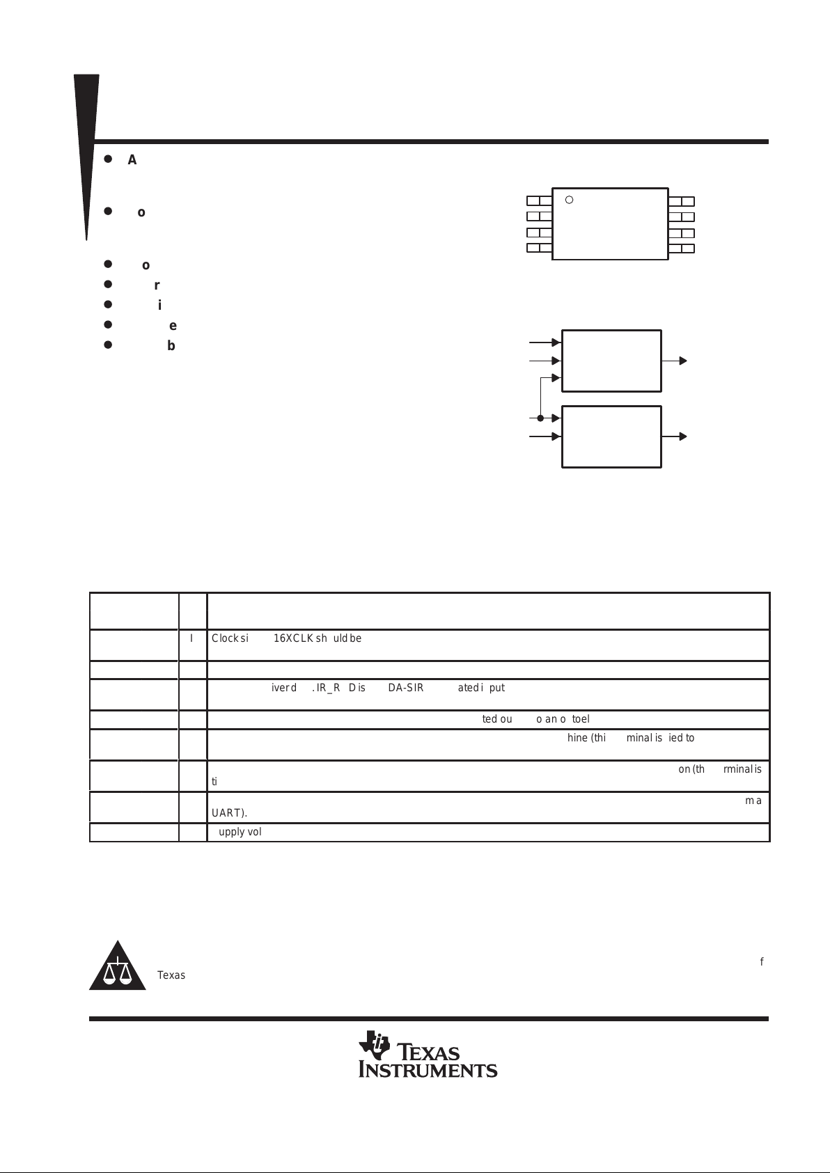
description
The TIR1000 serial infrared (SIR) encoder/
decoder is a CMOS device which encodes and
decodes bit data in conformance with the IrDA
specification.
A transceiver device is needed to interface to the photo-sensitive diode (PIN) and the light emitting diode (LED).
A UART is needed to interface to the serial data lines.
Terminal Functions
TERMINAL
NAME NO.
I/O
DESCRIPTION
Á
Á
16XCLK
Á
Á
1
I Clock signal. 16XCLK should be set to 16 times the baud rate. The highest baud rate for IrDA is 1 15.2 kbps for which the
clock frequency equals 1.843 MHz (this terminal is tied to the BAUDOUT of a UART).
GND
4
Ground
IR_RXD
6
I Infrared receiver data. IR_RXD is an IrDA-SIR-modulated input from an optoelectronics transceiver whose input pulses
should be 3/16 of the baud rate period.
IR_TXD
7
O Infrared transmitter data. IR_TXD is an IrDA-SIR-modulated output to an optoelectronics transceiver.
Á
Á
RESET
Á
Á
5
I Active high reset. RESET initializes an IrDA-SIR-decode/encode state machine (this terminal is tied to a UAR T reset
line).
U_RXD
3
O Receiver data. U_RXD is decoded (demodulated) data from IR_RXD according to the IrDA specification (this terminal is
tied to SIN of a UART).
Á
Á
U_TXD
Á
Á
2 I T ransmitter data. U_TXD is encoded (modulated) data and output data as IR_TXD (this terminal is tied to SOUT from a
UART).
V
CC
8 Supply voltage
Please be aware that an important notice concerning availability, standard warranty, and use in critical applications of
Texas Instruments semiconductor products and disclaimers thereto appears at the end of this data sheet.
IrDA is a registered trademark of the Infrared Data Association.
functional block diagram
1
2
3
4
8
7
6
5
16XCLK
U_TXD
U_RXD
GND
V
CC
IR_TXD
IR_RXD
RESET
PS OR PW PACKAGE
(TOP VIEW)
Decoder
Encoder
RESET
IR_RXD
16XCLK
U_TXD
U_RXD
IR_TXD
PRODUCTION DATA information is current as of publication date.
Products conform to specifications per the terms of Texas Instruments
standard warranty. Production processing does not necessarily include
testing of all parameters.
Copyright 1999, Texas Instruments Incorporated
TIR1000, TIR1000I
STANDALONE IrDA ENCODER AND DECODER
SLLS228F – DECEMBER 1995 – REVISED JUL Y 1999
2
POST OFFICE BOX 655303 • DALLAS, TEXAS 75265
absolute maximum ratings over operating free-air temperature range (unless otherwise noted)
†
Supply voltage range, VCC (see Note 1) –0.5 V to 6 V. . . . . . . . . . . . . . . . . . . . . . . . . . . . . . . . . . . . . . . . . . . . . . .
Input voltage range at any input, VI –0.5 V to VCC + 0.5 V. . . . . . . . . . . . . . . . . . . . . . . . . . . . . . . . . . . . . . . . . . . .
Output voltage range, V
O
–0.5 V to VCC + 0.5 V. . . . . . . . . . . . . . . . . . . . . . . . . . . . . . . . . . . . . . . . . . . . . . . . . . . .
Operating free-air temperature range, TA, TIR1000 0°C to 70°C. . . . . . . . . . . . . . . . . . . . . . . . . . . . . . . . . . . . . .
TA, TIR1000I –40°C to 85°C. . . . . . . . . . . . . . . . . . . . . . . . . . . . . . . . . . .
Storage temperature range, T
stg
–65°C to 150°C. . . . . . . . . . . . . . . . . . . . . . . . . . . . . . . . . . . . . . . . . . . . . . . . . . .
Case temperature for 10 seconds: SOP package 260°C. . . . . . . . . . . . . . . . . . . . . . . . . . . . . . . . . . . . . . . . . . . . .
†
Stresses beyond those listed under “absolute maximum ratings” may cause permanent damage to the device. These are stress ratings only, and
functional operation of the device at these or any other conditions beyond those indicated under “recommended operating conditions” is not
implied. Exposure to absolute-maximum-rated conditions for extended periods may affect device reliability.
NOTE 1: All voltage levels are with respect to GND.
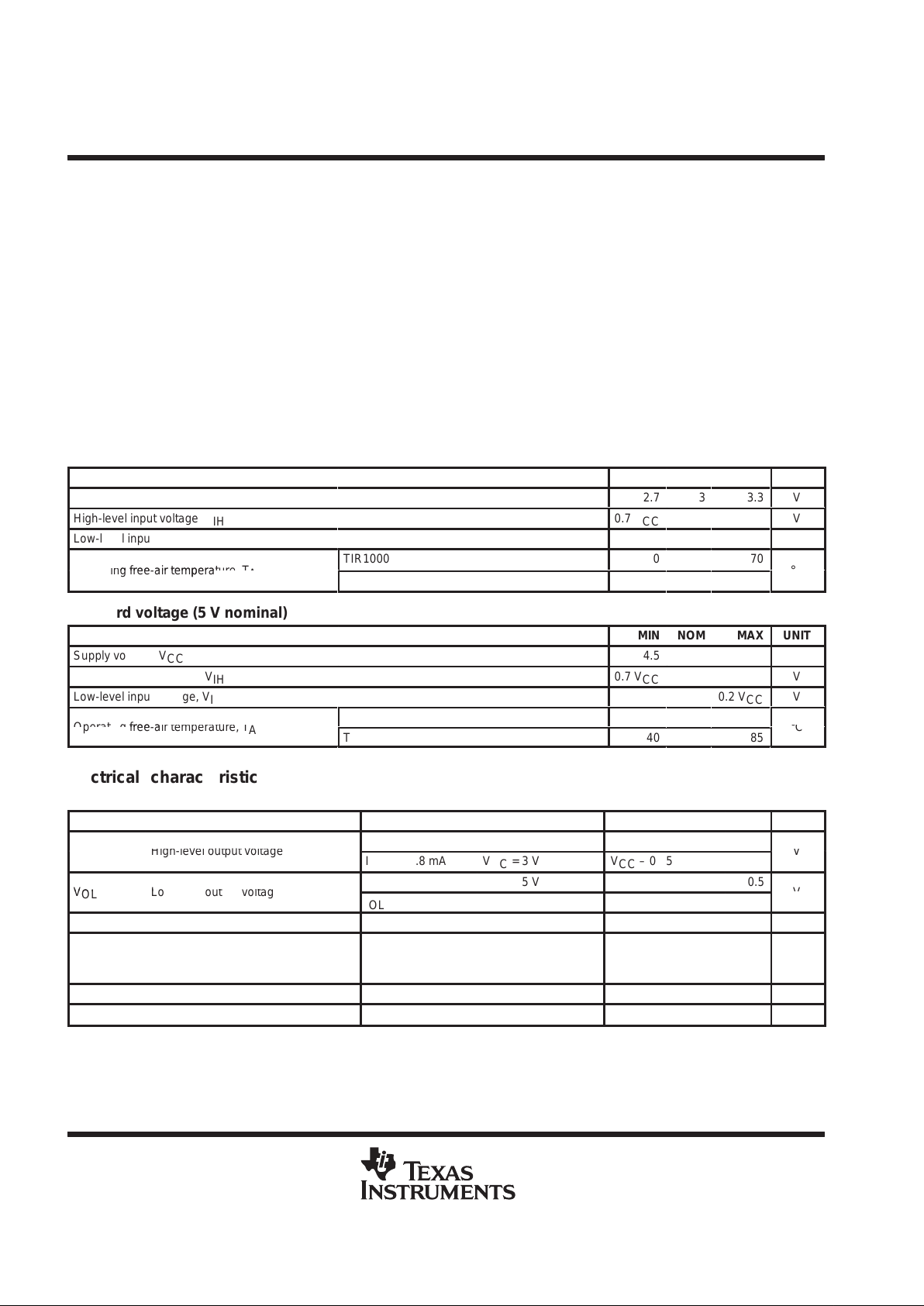
recommended operating conditions over recommended operating free-air temperature range
low voltage (3 V nominal)
MIN NOM MAX UNIT
Supply voltage, V
CC
2.7
3
3.3
V
High-level input voltage, V
IH
0.7 V
CC
V
Low-level input voltage, V
IL
0.2 V
CC
V
p
p
TIR1000
0
70
°
Operating free-air temperature, T
A
TIR1000I
–40
85
°C
standard voltage (5 V nominal)
MIN NOM MAX UNIT
Supply voltage, V
CC
4.5 5 5.5 V
High-level input voltage, V
IH
0.7 V
CC
V
Low-level input voltage, V
IL
0.2 V
CC
V
p
p
TIR1000
0
70
°
Operating free-air temperature, T
A
TIR1000I
–40
85
°C
electrical characteristics over recommended operating free-air temperature range (unless
otherwise noted)
PARAMETER TEST CONDITIONS MIN TYP MAX UNIT
p
IOH = –4 mA VCC = 5 V VCC – 0.8
VOHHigh-level output voltage
IOH = –1.8 mA VCC = 3 V VCC – 0.55
V
p
IOL = +4 mA VCC = 5 V 0.5
VOLLow-level output voltage
IOL = +1.8 mA VCC = 3 V 0.5
V
I
I
Input current VI = 0 to VCC, All other pins floating ±3 µA
I
CC
Supply current
VCC = 5.25 V ,
All inputs at 0.2 V ,
No load on outputs
TA = 25°C,
16XCLK at 2 MHz,
1 mA
C
i(16XCLK)
Clock input capacitance 5 pF
f
(16XCLK)
Clock frequency 2 MHz
TIR1000, TIR1000I
STANDALONE IrDA ENCODER AND DECODER
SLLS228F – DECEMBER 1995 – REVISED JUL Y 1999
3
POST OFFICE BOX 655303 • DALLAS, TEXAS 75265
switching characteristics
PARAMETER TEST CONDITIONS MIN TYP†MAX UNIT
t
r
Output rise time C
(LOAD)
= 15 pF (10% to 90%) 1.3 ns
t
f
Output fall time C
(LOAD)
= 15 pF (90% to 10%) 1.8 ns
†
Typical values are at TA = 25°C.
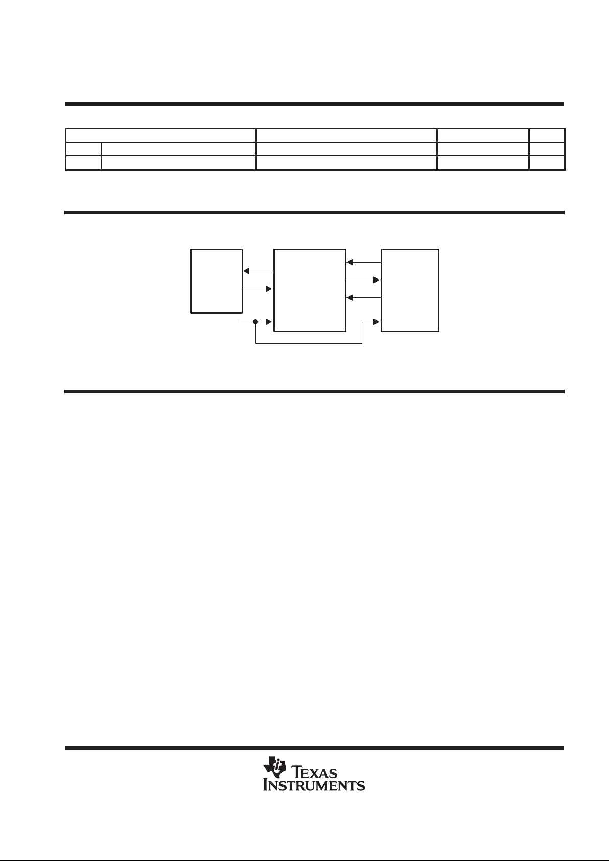
APPLICATION INFORMATION
To LED
From
TERMINAL
Optoelectronics
U_TXD
U_RXD
16XCLK
IR_TXD
IR_RXD
RESET
SOUT
SIN
BAUDOUT
RESET
TL16C550C UARTTIR1000, TIR1000I
Figure 1. Typical application of the TIR1000, TIR1000I
PRINCIPLES OF OPERATION
IrDA overview
The Infrared Data Association (IrDA) defines several protocols for sending and receiving serial infrared data,
including rates of 1 15.2 kbps, 0.576 Mbps, 1.152 Mbps, and 4 Mbps. The low rate of 115.2 kbps was specified
first and the others must maintain downward compatibility with it. At the 115.2 kbps rate, the protocol
implemented in the hardware is fairly simple. It primarily defines a serial infrared data
word
to be surrounded
by a start bit equal to 0 and a stop bit equal to 1. Individual bits are encoded or decoded the same whether they
are start, data, or stop bits. The TIR1000 and TIR1000I evaluate only single bits and only follow the 1 15.2 kbps
protocol. The 115.2 kbps rate is a maximum rate. When both ends of the transfer are set up to a lower but
matching speed, the protocol (with the TIR1000 and TIR1000I) still works. The clock used to code or sample
the data is 16 times the baud rate, or 1.843 Mhz maximum. To code a 1, no pulse is sent or received for 1-bit
time period, or 16 clock cycles. T o code a 0, one pulse is sent or received within a 1-bit time period, or 16 clock
cycles. The pulse must be at least 1.6 µs wide and 3 clock cycles long at 1.843 Mhz. At lower baud rates the
pulse can be 1.6 µs wide or as long as 3 clock cycles. The transmitter output, IR_TXD, is intended to drive a
LED circuit to generate an infrared pulse. The LED circuits work on positive pulses. A terminal circuit is expected
to create the receiver input, IR_RXD. Most, but not all, PIN circuits have inversion and generate negative pulses
from the detected infrared light. Their output is normally high. The TIR1000 and TIR1000I can decode either
negative or positive pulses on IR_RXD.

TIR1000, TIR1000I
STANDALONE IrDA ENCODER AND DECODER
SLLS228F – DECEMBER 1995 – REVISED JUL Y 1999
4
POST OFFICE BOX 655303 • DALLAS, TEXAS 75265
PRINCIPLES OF OPERATION
IrDA encoder function
Serial data from a UART is encoded to transmit data to the optoelectronics. While the serial data input to this
block (U_TXD) is high, the output (IR_TXD) is always low, and the counter used to form a pulse on IR_TXD is
continuously cleared. After U_TXD resets to 0, IR_TXD rises on the falling edge of the seventh 16XCLK. On
the falling edge of the tenth 16XCLK pulse, IR_TXD falls, creating a 3-clock-wide pulse. While U_TXD stays
low, a pulse is transmitted during the seventh to tenth clocks of each 16-clock bit cycle.
U_TXD
16XCLK
IR_TXD
1234567 8 10 12 14 16
СССССССССССС
Figure 2. IrDA-SIR Encoding Scheme –
Detailed Timing Diagram
Figure 3. Encoding Scheme – Macro View
16XCLK
U_TXD
IR_TXD
16 Cycles 16 Cycles 16 Cycles 16 Cycles
IrDA decoder function
After reset, U_RXD is high and the 4-bit counter is cleared. When a falling edge is detected on IR_RXD, U_RXD
falls on the next rising edge of 16XCLK with sufficient setup time. U_RXD stays low for 16 cycles (16XCLK) and
then returns to high as required by the IrDA specification. As long as no pulses (falling edges) are detected on
IR_RXD, U_RXD remains high.
IR_RXD
16XCLK
U_RXD
1 2 3 4 5 6 7 8 10 12 14 16
Figure 4. IrDA-SIR Decoding Scheme –
Detailed Timing Diagram
Figure 5. Decoding Scheme – Macro View
16XCLK
IR_RXD
U_RXD
16 Cycles 16 Cycles 16 Cycles 16 Cycles

TIR1000, TIR1000I
STANDALONE IrDA ENCODER AND DECODER
SLLS228F – DECEMBER 1995 – REVISED JUL Y 1999
5
POST OFFICE BOX 655303 • DALLAS, TEXAS 75265
PRINCIPLES OF OPERATION
IrDA encoder function (continued)
It is possible for jitter or slight frequency differences to cause the next falling edge on IR_RXD to be missed for
one 16XCLK cycle. In that case, a 1-clock-wide pulse appears on U_RXD between consecutive zeroes. It is
important for the UART to strobe U_RXD in the middle of the bit time to avoid latching this 1-clock-wide pulse.
The TL16C550C UART already strobes incoming serial data at the proper time. Otherwise, note that data is
required to be framed by a leading zero and a trailing one. The falling edge of that first zero on U_RXD
synchronizes the read strobe. The strobe occurs on the eighth 16XCLK pulse after the U_RXD falling edge and
once every 16 cycles thereafter until the stop bit occurs.
1 2 3 4 5 6 7 8 10 12 14 16 1 2 3 4 5 6 7 8 10 12 14 16
IR_RXD
16XCLK
U_RXD
Figure 6. Timing Causing 1-clock-wide Pulse Between Consecutive Ones
16 Cycles 16 Cycles
16 Cycles
7 Cycles
16XCLK
IR_RXD
U_RXD
External Strobe
Figure 7. Recommended Strobing For Decoded Data

TIR1000, TIR1000I
STANDALONE IrDA ENCODER AND DECODER
SLLS228F – DECEMBER 1995 – REVISED JUL Y 1999
6
POST OFFICE BOX 655303 • DALLAS, TEXAS 75265
PRINCIPLES OF OPERATION
IrDA encoder function (continued)
The TIR1000 and TIR1000I can decode positive pulses on IR_RXD. The timing is different, but the variation
is invisible to the UART. The decoder , which works from the falling edge, now recognizes a zero on the trailing
edge of the pulse rather than on the leading edge. As long as the pulse width is fairly constant, as defined by
the specification, the trailing edges should also be 16 clock cycles apart and data can readily be decoded. The
zero appears on U_RXD after the pulse rather than at the start of it.
12345678 10 12 14 16
IR_RXD
16XCLK
U_RXD
Figure 8. Positive IR_RXD Pulse Decode – Detailed View
16
Cycles
16
Cycles
16
Cycles
16
Cycles
16XCLK
IR_RXD
U_RXD
Figure 9. Positive IR_RXD Pulse Decode – Macro View

TIR1000, TIR1000I
STANDALONE IrDA ENCODER AND DECODER
SLLS228F – DECEMBER 1995 – REVISED JUL Y 1999
7
POST OFFICE BOX 655303 • DALLAS, TEXAS 75265
MECHANICAL DATA
PS (R-PDSO-G8) PLASTIC SMALL-OUTLINE PACKAGE
4040063/B 02/95
Seating Plane
0,05 MIN
2,00 MAX
1
5,90
6,50
4
8 5
5,00
7,40
5,60
8,20
Gage Plane
0,15 NOM
0,25
0,95
0,55
0,10
1,27
M
0,25
0°–8°
0,35
0,51
NOTES: A. All linear dimensions are in millimeters.
B. This drawing is subject to change without notice.
C. Body dimensions do not include mold flash or protrusion, not to exceed 0,15.

TIR1000, TIR1000I
STANDALONE IrDA ENCODER AND DECODER
SLLS228F – DECEMBER 1995 – REVISED JUL Y 1999
8
POST OFFICE BOX 655303 • DALLAS, TEXAS 75265
MECHANICAL DATA
PW (R-PDSO-G**) PLASTIC SMALL-OUTLINE PACKAGE
4040064/D 10/95
14 TERMINAL SHOWN
Seating Plane
0,10 MIN
1,20 MAX
1
A
7
14
0,19
4,50
4,30
8
6,10
6,70
0,32
0,75
0,50
0,25
Gage Plane
0,15 NOM
0,65
M
0,13
0°–8°
0,10
PINS **
A MIN
A MAX
DIM
2,90
3,10
8
4,90
5,10
14
6,60
6,404,90
5,10
16
7,70
20
7,90
24
9,60
9,80
28
NOTES: A. All linear dimensions are in millimeters.
B. This drawing is subject to change without notice.
C. Body dimensions do not include mold flash or protrusion not to exceed 0,15.
D. Falls within JEDEC MO-153

IMPORTANT NOTICE
T exas Instruments and its subsidiaries (TI) reserve the right to make changes to their products or to discontinue
any product or service without notice, and advise customers to obtain the latest version of relevant information
to verify, before placing orders, that information being relied on is current and complete. All products are sold
subject to the terms and conditions of sale supplied at the time of order acknowledgement, including those
pertaining to warranty, patent infringement, and limitation of liability.
TI warrants performance of its semiconductor products to the specifications applicable at the time of sale in
accordance with TI’s standard warranty. Testing and other quality control techniques are utilized to the extent
TI deems necessary to support this warranty. Specific testing of all parameters of each device is not necessarily
performed, except those mandated by government requirements.
CERT AIN APPLICATIONS USING SEMICONDUCTOR PRODUCTS MAY INVOLVE POTENTIAL RISKS OF
DEATH, PERSONAL INJURY, OR SEVERE PROPERTY OR ENVIRONMENTAL DAMAGE (“CRITICAL
APPLICATIONS”). TI SEMICONDUCTOR PRODUCTS ARE NOT DESIGNED, AUTHORIZED, OR
WARRANTED TO BE SUITABLE FOR USE IN LIFE-SUPPORT DEVICES OR SYSTEMS OR OTHER
CRITICAL APPLICATIONS. INCLUSION OF TI PRODUCTS IN SUCH APPLICA TIONS IS UNDERSTOOD T O
BE FULLY AT THE CUSTOMER’S RISK.
In order to minimize risks associated with the customer’s applications, adequate design and operating
safeguards must be provided by the customer to minimize inherent or procedural hazards.
TI assumes no liability for applications assistance or customer product design. TI does not warrant or represent
that any license, either express or implied, is granted under any patent right, copyright, mask work right, or other
intellectual property right of TI covering or relating to any combination, machine, or process in which such
semiconductor products or services might be or are used. TI’s publication of information regarding any third
party’s products or services does not constitute TI’s approval, warranty or endorsement thereof.
Copyright 1999, Texas Instruments Incorporated
 Loading...