

Page 1

TAS5102EVM and TAS5103EVM for the
TAS5102 and TAS5103 Digital Amplifier Power
Output Stages
User's Guide
Literature Number: SLLU106
August 2008
Page 2

2 SLLU106 – August 2008
Submit Documentation Feedback
Page 3

Contents
1 Related Documentation from Texas Instruments ...................................................................... 5
1.1 Additional Documentation ................................................................................................ 5
2 Overview ............................................................................................................................. 5
2.1 TAS5102EVM and TAS5103EVM Features ........................................................................... 6
2.2 PCB Key Map.............................................................................................................. 6
3 Quick-Setup Guide ............................................................................................................... 7
3.1 Electrostatic Discharge Warning ........................................................................................ 7
3.2 Unpacking the EVM ....................................................................................................... 7
3.3 Power Supply Setup ...................................................................................................... 7
3.4 GUI Software Installation ................................................................................................. 8
3.5 Operational Sequence and Indicators .................................................................................. 9
4 System Interfaces ................................................................................................................ 9
4.1 Power Supply (PSU) Interface (PVDD and GND) .................................................................... 9
4.2 J1 Amplifier Connection to MC012 Controller Module .............................................................. 10
4.3 Loudspeaker Connectors (J3 - J6) .................................................................................... 10
4.4 SPDIF Optical Input Connector ........................................................................................ 11
4.5 SPDIF Co-Axial Input Connector ...................................................................................... 11
4.6 USB Connector .......................................................................................................... 11
5 Protection .......................................................................................................................... 11
5.1 Short-Circuit Protection and Fault-Reporting Circuitry .............................................................. 11
5.2 Fault Reporting ........................................................................................................... 11
Appendix A Design Documents ................................................................................................... 12
A.1 HPL-MC012 Schematic ................................................................................................. 12
A.2 HPL-MC012 Composite Drawings .................................................................................... 14
A.3 TAS5102/3EVM Schematic ............................................................................................ 15
A.4 TAS5102/3EVM Composite Drawings ................................................................................ 16
A.5 Heat Sink Drawing ....................................................................................................... 19
A.6 Parts List .................................................................................................................. 19
Important Notices ............................................................................................................... 24
SLLU106 – August 2008 Table of Contents 3
Submit Documentation Feedback
Page 4

www.ti.com
List of Figures
1 Physical Structure for TAS5102/3EVM ................................................................................... 6
2 Modulator and Power Stage Board Connection Example .............................................................. 7
3 TAS5086 GUI Window ...................................................................................................... 8
4 Recommended Power-Up Sequence .................................................................................... 10
List of Tables
1 Related Documentation From Texas Instruments ....................................................................... 5
2 Recommended Supply Voltage ............................................................................................ 8
3 Recommended Supply Voltages ........................................................................................... 9
4 J9/J10 Pin Description Amplifier/Controller Connector ................................................................ 10
5 Output Pin Description ..................................................................................................... 10
6 TAS5102 Warning/Error Signal Decoding .............................................................................. 11
A-1 Bill of Materials for HPL-MC012 .......................................................................................... 19
A-2 Bill of Materials for TAS5103EVM ....................................................................................... 21
A-3 Bill of Materials for TAS5102EVM ....................................................................................... 22
4 List of Figures SLLU106 – August 2008
Submit Documentation Feedback
Page 5
TAS5102EVM and TAS5103EVM for the TAS5102 and
TAS5103 Digital Amplifier Power Output Stages
This user's guide describes the operation of the TAS5102 and TAS5103 evaluation modules (EVM) from
Texas Instruments.
1 Related Documentation from Texas Instruments
Table 1 contains a list of data sheets that have detailed descriptions of the integrated circuits used in the
design of the HPL-MC012 Modulator/Controller Module which accompanies the TAS5102EVM and
TAS5103EVM as well as the link to the TAS5102/3 data sheet. These documents can be obtained from
the Texas Instruments Web site at http://www.ti.com .
User's Guide
SLLU106 – August 2008
Table 1. Related Documentation From Texas
Instruments
Part Number Literature Number
TAS5086 SLES131
TAS5102/3 SLLS801
TUSB3210 SLLS466
UA78M12CKTPR SLVS059
TPS40200D SLUS659
TPS3825-33DBVT SLVS165
1.1 Additional Documentation
• Personal Computer (PC) Configuration Tool for TAS5086 (TAS5086 GUI version 4.0 or later). This
software comes on the compact disk in the EVM package.
2 Overview
The TAS5102EVM and TAS5103EVM packages are composed of two separate modules, the HPL-MC012
Modulator/Controller Module and the TAS5102EVM or TAS5103EVM Amplifier Module. They are
designed so that the user can separate the two modules and connect the TAS5102EVM or TAS5103EVM
Amplifier Module into a target system via a ribbon cable. Keep this ribbon cable as short as possible to
avoid degradation in the PWM signals.
The TAS5102 and TAS5103 customer evaluation amplifier modules each demonstrate two audio
integrated circuits — the TAS5086 and the TAS5102 or TAS5103 from Texas Instruments (TI).
The TAS5086DBT is a high-performance, 32-bit (24-bit input), multichannel PurePath Digital™ pulse width
modulator (PWM) based on Equibit™ technology with fully symmetrical AD modulation scheme. It accepts
an input sample rate from 32 kHz to 192 kHz. The device also has digital audio processing (DAP) that
provides bass management, advanced performance, and a high level of system integration.
The TAS5102 is a compact, high-power, digital amplifier power stage designed to drive an 8- Ω
loudspeaker up to 20 W/channel at 10% THD+N. It contains integrated gate-drive, four matched and
electrically isolated enhancement-mode N-channel power DMOS transistors, and protection/fault-reporting
circuitry. The DAD package has a PowerPAD™ package on the top side for heat transfer through a heat
sink. The heat sink in this design is for evaluation purposes only.
PurePath Digital, Equibit, PowerPAD are trademarks of Texas Instruments.
Windows is a trademark of Mircrosoft Corporation.
SLLU106 – August 2008 TAS5102EVM and TAS5103EVM for the TAS5102 and TAS5103 Digital Amplifier Power Output Stages 5
Submit Documentation Feedback
Page 6
SPDIFReceiver 3.3VSMPS
USBController TAS5086
TAS5102
Power
Supply
Overview
The TAS5103 is a compact, high-power, digital amplifier power stage designed to drive an 8- Ω
loudspeaker up to 15 W/channel at 10% THD+N. It contains integrated gate-drive, four matched and
electrically isolated enhancement-mode N-channel power DMOS transistors, and protection/fault-reporting
circuitry. The DAP package has a PowerPAD™ package on the bottom side for heat transfer through the
printed-circuit board.
Either of these EVMs plus the HPLMC-012 form a complete two-channel, digital audio amplifier system
which includes digital input (S/PDIF), control interface (via USB) to PC and DAP (digital audio processor)
features like digital volume control, bass management, and input and output multiplexers.
This EVM is designed to illustrate a low-cost approach to an amplifier design using this device. Improved
performance, at increased cost, can be achieved with a high-performance configuration.
2.1 TAS5102EVM and TAS5103EVM Features
• Modular approach comprised of TAS5102EVM or TAS5103EVM amplifier modules and HPL-MC012
modulator/controller module
• Two-channel evaluation module.
• Self-contained protection system (short-circuit and thermal).
• Standard I2S and I2C control via SPDIF and USB
• Double-sided, plated-through printed-circuit board (PCB) layout
• Single power supply operation
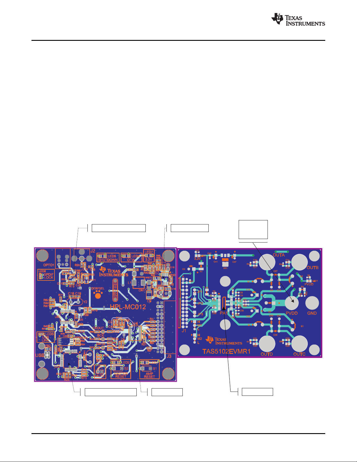
2.2 PCB Key Map
Physical structure for the TAS5102/3EVM is illustrated in Figure 1 .
www.ti.com
Figure 1. Physical Structure for TAS5102/3EVM
TAS5102EVM and TAS5103EVM for the TAS5102 and TAS5103 Digital Amplifier Power Output Stages6 SLLU106 – August 2008
Submit Documentation Feedback
Page 7
www.ti.com
3 Quick-Setup Guide
This section describes the TAS5102/3EVM board in regards to power supplies and system interfaces. It
provides information regarding handling and unpacking, absolute operating conditions, and a description
of the factory default switch and jumper configuration.
The section also provides a step-by-step guide to configuring the TAS5102/3EVM for device evaluation.
3.1 Electrostatic Discharge Warning
Many components on the TAS5102/3EVM are susceptible to damage by electrostatic discharge (ESD).
Customers are advised to observe proper ESD handling precautions when unpacking and handling the
EVM, including the use of a grounded wrist strap at an approved ESD workstation.
Failure to observe ESD handling procedures can result in damage to EVM
components.
3.2 Unpacking the EVM
On opening the TAS5086-TAS5102EVM or TAS51033EVM package, ensure that the following items are
included:
• 1 pc. TAS5102/3 EVM Power Stage Board
• 1 pc. HPL-MC012 Modulator/Input Board
• Because this system has standard connectors, no cables are supplied
• 1 pc. TAS5102/3EVM CD-ROM.
If any of these items are missing, contact the Texas Instruments Product Information Center nearest you
to inquire about a replacement.
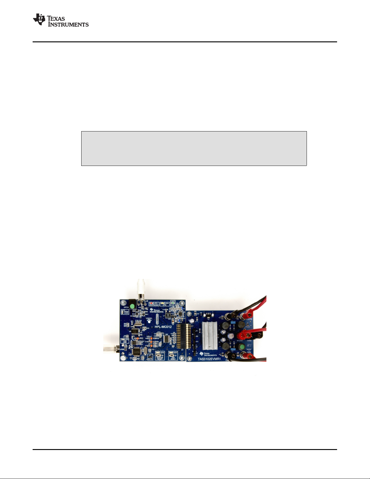
Connect the Modulator/Input board to the Power Stage board with the docking connectors on each board.
Use care because this connector is not keyed.
Quick-Setup Guide
CAUTION
Figure 2. Modulator and Power Stage Board Connection Example
3.3 Power Supply Setup
To power up the EVM, one power supply is needed for system power, logic and gate-drive, and for output
stage supply. The power supply is connected to the EVM with banana cables or stripped insulated wire.
SLLU106 – August 2008 TAS5102EVM and TAS5103EVM for the TAS5102 and TAS5103 Digital Amplifier Power Output Stages 7
Submit Documentation Feedback
Page 8
Quick-Setup Guide
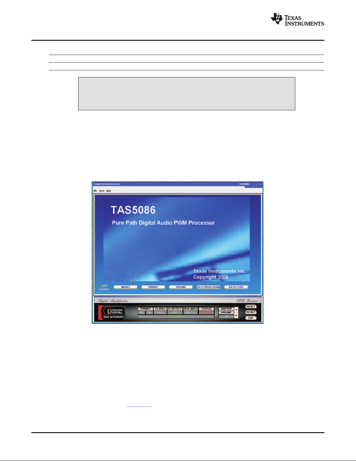
3.4 GUI Software Installation
The TAS5086 GUI provides easy control of all registers in TAS5086. To install the GUI, run the setup file
from the TAS5102/3 CD-ROM.
After installation, turn on the power supply, and connect the USB cable to the Modulator/Controller board.
Start the GUI program from The Windows™ menu. (Program Files/Texas Instruments Inc) The start-up of
the GUI takes few seconds.
www.ti.com
Table 2. Recommended Supply Voltage
Description Voltage Limitations Current Requirement Connector
Output stage power supply 8 V – 23 V 5 A Red/black
CAUTION
Applying voltages above the limitations given in Table 2 can cause permanent
damage to your hardware.
Figure 3. TAS5086 GUI Window
From the files menu, load the configuration file:
TAS5102 EVM Configuration.cfg
The file is located on the TAS5102/3EVM CD-ROM. This file contains all settings for a default setup of the
EVM.
For easy access of the file, it is recommended to copy the files into directory where the GUI is installed.
Default is C:\Program Files\Texas Instruments Inc\TAS5086\.
For more advanced use of the GUI and the features of the TAS5086 modulator, see the GUI User’s Guide
and the TAS5086 data sheet (SLES131 ). The GUI User's Guide can be accessed by clicking on Help in
the toolbar and then selecting User's Guide in the drop-down menu.
TAS5102EVM and TAS5103EVM for the TAS5102 and TAS5103 Digital Amplifier Power Output Stages8 SLLU106 – August 2008
Submit Documentation Feedback
Page 9

www.ti.com
3.5 Operational Sequence and Indicators
• After connecting the power supply and turning it on, the power supply current must be ~50 mA. The
amplifier reset LED must be on.
– The PVDD and 3.3-V LEDs must be on. If not, check the connections to the power supply.
• Connect the SPDIF cable, either optical or coaxial, to an SPDIF source.
• Connect the USB cable and the USB LED (blue LED must be on).
– The EVM must enumerate without the installation of a USB driver; it is a Windows™ audio class
device.
• Start the GUI. (It must not give an indication of COMMUNICATION ERROR).
– C:\Program Files\Texas Instruments Inc\TAS5086 GUI
• Load the configuration file.
– (File, Load, Config File, TAS5102 EVM Configuration.cfg)
– The AMP RESET LED must go off.
– The power supply current must be ~100 mA.
– This indicates that the amplifier is switching and ready for audio input.
– The SPDIF indicator must be on (blue LED), when locked to a valid source of SPDIF.
• If the preceding conditions are met, the EVM system is ready to accept audio data.
– Note: The default gain setting of the TAS5086 GUI is 0 dB. If you are connecting directly from a
music source (CD player) for input and speakers for output, you may want to use the volume
control function of GUI to reduce the gain before the program material is started.
System Interfaces
4 System Interfaces
This section describes the TAS5102/3 EVM board in regards to power supplies and system interfaces.
4.1 Power Supply (PSU) Interface (PVDD and GND)
The TAS5102/3 EVM module must be powered from a well-regulated external power supply. Good audio
performance requires a stabilized power supply with low ripple voltage and low output impedance.
Note: The length of power supply cable must be minimized. Increasing the length of the PSU cable
is equal to increasing the distortion for the amplifier at high output levels and low
frequencies.
Maximum output stage supply voltage depends of the speaker load resistance. For the recommended
maximum supply voltage, see the TAS5102/3 data sheet (SLLS801 ).
Table 3. Recommended Supply Voltages
Description Current Recommendations
Output stage power supply 8 V – 23 V 5 A
Voltage Limitations
(8- Ω Load)
SLLU106 – August 2008 TAS5102EVM and TAS5103EVM for the TAS5102 and TAS5103 Digital Amplifier Power Output Stages 9
Submit Documentation Feedback
Page 10

Outputstagepowersupply
RESET
>1ms
Systempowersupply
System Interfaces
The recommended TAS5102/3 power-up sequence is shown in Figure 4 . For proper TAS5102/3
operation, the RESET signal should be kept low during power up. RESET is pulled low during power up
for 200 ms by the onboard reset generator (U2).
Figure 4. Recommended Power-Up Sequence
4.2 J1 Amplifier Connection to MC012 Controller Module
Table 4. J9/J10 Pin Description Amplifier/Controller Connector
Pin No. Description
1, 2, 5, 6 ,10, 11, 28 DGND Low-current ground for modulator/controller
3, 4 PVDD1 PVDD buffered through 24- Ω resistor to power the modulator/controller
7 OTW Overtemperature warning from the amplifier (T > 125 ° C)
8, 9, 13, 15, 17, 19, 20, 21,
22, 23, 25, 27
12 PWM_A Channel A PWM signal from modulator
14 PWM_B Channel B PWM signal from modulator
16 PWM_C Channel C PWM signal from modulator
18 PWM_D Channel D PWM signal from modulator
24 RESET Resets the TAS5102/3
26 FAULT Power stage fault indicator
Net-Name at
Schematics
NC Not connected
www.ti.com
4.3 Loudspeaker Connectors (J3 - J6)
TAS5102EVM and TAS5103EVM for the TAS5102 and TAS5103 Digital Amplifier Power Output Stages10 SLLU106 – August 2008
CAUTION
Both positive and negative speaker outputs are floating and may not be
connected to ground (e.g., through an oscilloscope).
Table 5. Output Pin Description
Net-Name at Schematics Description
OUT_A Speaker positive output
OUT_B Speaker negative output
OUT_C Speaker positive output
OUT_D Speaker negative output
Submit Documentation Feedback
Page 11

www.ti.com
4.4 SPDIF Optical Input Connector
This connector is a standard TOSLINK connector that connects the SPDIF digital audio input to the SPDIF
receiver on the HPL-MC012 PCB. This connector, or the SPDIF co-axial input, is used, but not both
connectors at the same time.
4.5 SPDIF Co-Axial Input Connector
This connector is a standard RCA connector that connects the SPDIF digital audio input to the SPDIF
receiver on the HPL-MC012 PCB. This connector, or the SPDIF optical Input, is used, but not both
connectors at the same time.
4.6 USB Connector
This connector is a standard USB connector and is used to connect GUI control information from a PC to
the HPL-MC012 PCB. The USB system does not stream audio from a PC.
5 Protection
This section describes the short-circuit protection and fault-reporting circuitry of the TAS5102/3 device.
5.1 Short-Circuit Protection and Fault-Reporting Circuitry
The TAS5102/3 is a self-protecting device that provides fault reporting (including high-temperature
protection and short-circuit protection). For highest possible reliability, recovering from a fault requires
external reset of the device. This is done by the TAS5086 on the HPL-MC012 board. See the TAS5102/3
data sheet for more information regarding the RESET function.
Protection
5.2 Fault Reporting
The OTW and FAULT outputs from TAS5102/3 indicate fault conditions. See the TAS5102/3 data sheet
(SLLS801 ) for a description of these pins.
Table 6. TAS5102 Warning/Error Signal Decoding
FAULT OTW Device Condition
0 0
0 1
1 0 Junction temperature lower than 125 ° C and no faults (normal operation)
1 1 Junction temperature higher than 125 ° C (overtemperature warning)
The FAULT output is open-drain. The OTW output is push-pull active high.
The OTW LED on the MC012 is illuminated when the temperature of the TAS5102/3 is okay (less than
125 ° C.) The LED turns off when the TAS5102/3 is warning of overtemperature on the device (T
This polarity is due to a reversal of polarity of the OTW pin from other devices (e.g., TAS5132) which also
use this modulator board.
Overcurrent (OC) or undervoltage (UVP) warning or overtemperature error
(OTE)
Overtemperature warning (OTW) or overcurrent (OC) or undervoltage
(UVP)
J
> 125 ° C.)
SLLU106 – August 2008 TAS5102EVM and TAS5103EVM for the TAS5102 and TAS5103 Digital Amplifier Power Output Stages 11
Submit Documentation Feedback
Page 12

of
Filename:
Mod: PCBRev: Sheet
SaveDate:
CX
SchematicRev:
Design
Team:
DrawnBy:
TI
PrintDate
PROJECT:
of
Filename:
Mod: PCBRev: Sheet
SaveDate:
CX
SchematicRev:
Design
Team:
DrawnBy:
TI
PrintDate
PROJECT:
1
1
100
0
0
1
1
001
0
1
I
I
OOO
O
O
1
0
0
1
0
0
1
1
NC
4
1
0
O
FROM
MATING
7
6
503
1
2
1
0
101
1
0
L/H
H/L
L/H
H/L
H/L
H/L
H/L
3.3V
64fs
64fs
64fs
64fs
64fs
I
I
OOO
O
O
SET
TO
SET TO
OCKS1
NC
NC
Xtal
512fs
256fs
256fs
128fs
1
54kHz
108kHz
fs(MAX)
108kHz
216kHz
LDN
MODE
4
DIF1
0
H/L
I/O
64fs
I/O
O
I2S
CONTROLLERFOR
T
AS5132DDV2EVM
OPTICAL INPUT
RCA
INPUT
SUPPL
Y
64-128fs
64-128fs
24Bit/I2S
24Bit/LJ
24Bit/I2S
16Bit/RJ
24Bit/RJ
18Bit/RJ
20Bit/RJ
LRCK BICK/BCK
RESET
FROM
CONTROL
256/256/108
OCKS0
TueDec19,2006
I2SOUT
512fs
256fs
256fs
MCLK01
128fs
CONNECTOR
DIF2 DIF0
POWER
SWITCHING
L/R LRCK
SDTO/DATA
24Bit/LJ
U5
AK41
13VF
HPL-MC012.sch
DECEMBER72006
SPDIFLock
AUDIOSERIAL INTERFACEFORMAT
FREDSHIPLEY
MASTERCLOCKOUTPUT FREQUENCY
SPDIF/3.3VSWITCHINGPOWERSUPPLY
Appendix A
Appendix A Design Documents
A.1 HPL-MC012 Schematic
www.ti.com
12 Design Documents SLLU106 – August 2008
Submit Documentation Feedback
Page 13

of
Filename:
Mod: PCBRev: Sheet
SaveDate:
CX
SchematicRev:
Design
Team:
DrawnBy:
TI
PrintDate
PROJECT:
of
Filename:
Mod: PCBRev: Sheet
SaveDate:
CX
SchematicRev:
Design
Team:
DrawnBy:
TI
PrintDate
PROJECT:
NC
4
USBIN
TO
NC
NC
2
LDN
CONTROLLERFOR TAS5132DDV2EVM
I2SIN
AMP
USBLINK
MUTE
TueDec19,2006
WARNING
OVER
SHUT
DOWN
T
AS5132DDV2EVM
TO
SPDIF
TEMP
U4
TAS5086DBT
HPL-MC012.sch
DECEMBER72006
MASTER
RESET CONTROL
FREDSHIPLEY
USBINPUT /RESET /PWMMODULATOR
www.ti.com
HPL-MC012 Schematic
SLLU106 – August 2008 Design Documents 13
Submit Documentation Feedback
Page 14

HPL-MC012 Composite Drawings
A.2 HPL-MC012 Composite Drawings
www.ti.com
Design Documents14 SLLU106 – August 2008
Submit Documentation Feedback
Page 15

of
Filename:
Mod:
PCBRev: Sheet
SaveDate:
CX
SchematicRev:
Design Team:
DrawnBy:
TI
PrintDate
PROJECT
:
of
Filename:
Mod:
PCBRev: Sheet
SaveDate:
CX
SchematicRev:
Design Team:
DrawnBy:
TI
PrintDate
PROJECT
:
0
0
1
0
1
0
A
1 1
LDN
INPUTS
M1
TM
JP1
JP3 M1 M2
BDMODE*
ADMODE
1
NC
EMI
3
JP1
JP2
JP3
CONTROLLER
WedJul30,2008
CURT STEPHENS
2.0CHBTL TAS5102DADEVAL BOARD
Range=8-23V
POWERSUPPLY
EMI
SNUBBER
M2
2N AD/BDModulation
PWMInput
1N ADModulation
1N ADModulation
2ChannelBTL
2ChannelBTL
4ChannelSE
MODE
T
ABLE
(TAS5086)
(ADMODE)
BTL Mode
ProtectionScheme
Same AsBTLMode+
InSEModeOUT_xIsHi-Z
BTL Mode*
(TAS5012)
(BDMODE)
JP2
BOMONLY
RECONSTRUCTIONFILTER
1
OUTPUT
CONNECTIONS
SNUBBERS
RESER
VED
RESER
VED
OUT
1-2
OUT
HPL-MC012
RESER
VED
IN
2-3
IN
HPL-MC013
*BOARDSHIPPEDINBDMODE
TAS5102EVMR1.sch
JUL
Y 29,2008
OutputConfiguration
PWMMODEJUMPERS
TAS5102DAD
U1
*BOARDSHIPPEDIN2N-BTL MODE
20WA
TT
STEREOPUREPATHDIGITAL POWER AMP
www.ti.com
A.3 TAS5102/3EVM Schematic
TAS5102/3EVM Schematic
SLLU106 – August 2008 Design Documents 15
Submit Documentation Feedback
Page 16
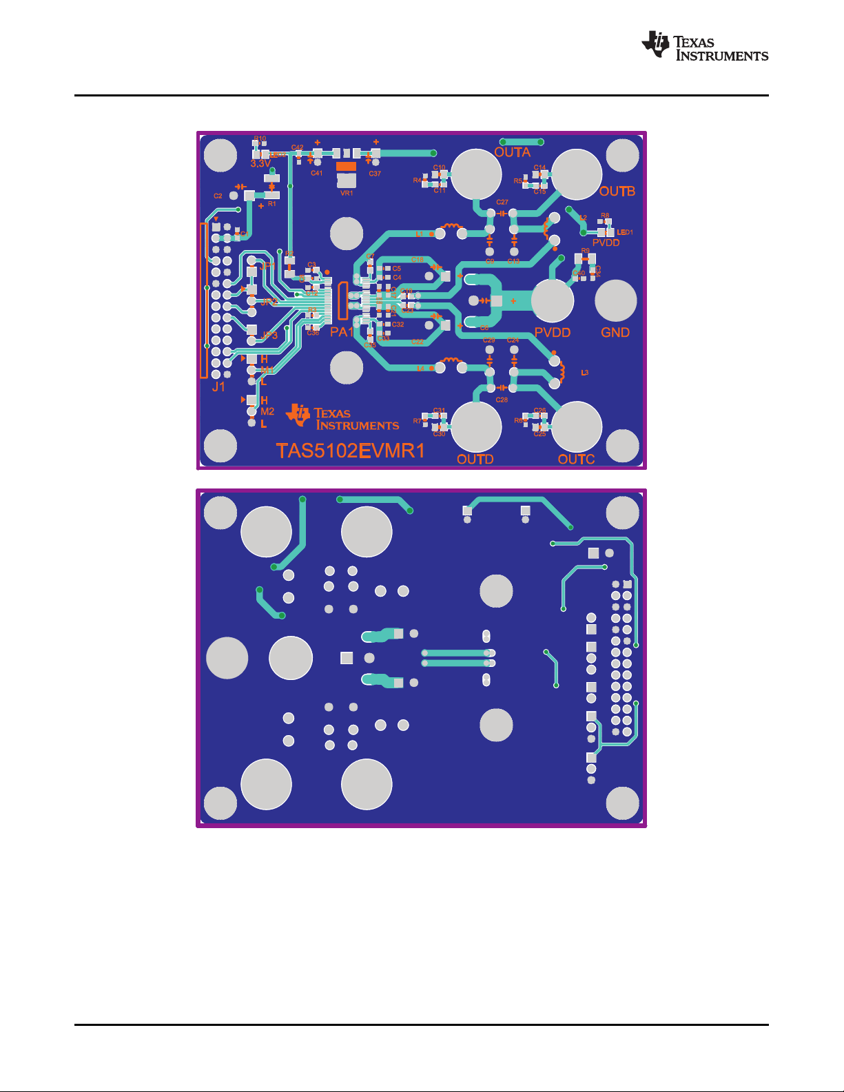
TAS5102/3EVM Composite Drawings
A.4 TAS5102/3EVM Composite Drawings
www.ti.com
16 Design Documents SLLU106 – August 2008
Submit Documentation Feedback
Page 17

of
Filename:
Mod: PCBRev: Sheet
SaveDate:
CX
SchematicRev:
Design
Team:
DrawnBy:
TI
PrintDate
PROJECT:
of
Filename:
Mod: PCBRev: Sheet
SaveDate:
CX
SchematicRev:
Design
Team:
DrawnBy:
TI
PrintDate
PROJECT:
0
0
1
1
0
1
0
1
A
LDN
INPUTS
JP1
JP2
JP3
IN
2-3
IN
TM
JP1
JP3 M1
M2
BDMODE*
ADMODE
1
NC
EMI
3
M1
WedJul30,2008
CURT STEPHENS
2.0CHBTL TAS5103DAPEVAL BOARD
Range=8-23V
EMI
POWERSUPPLY
SNUBBER
OUT
1-2
OUT
2N AD/BDModulation
1N
ADModulation
2ChannelBTL
2ChannelBTL
1N ADModulation 4ChannelSE
RESERVED RESERVED
MODE
T
ABLE
HPL-MC013
(TAS5012)
BTL
Mode
BTL Mode*
Same
AsBTL Mode+
InSEModeOUT_xIsHi-Z
RESER
VED
JP2
RECONSTRUCTIONFIL
TER
*BOARDSHIPPEDINBDMODE
1
OUTPUT
CONNECTIONS
SNUBBERS
CONTROLLER
M2 PWMInput
(BDMODE)
ProtectionScheme
TAS5103EVM.sch
JULY29,2008
BOMONL
Y
HPL-MC012
(TAS5086)
PWMMODEJUMPERS
(ADMODE)
OutputConfiguration
TAS5103DAP
PA1
*BOARDSHIPPEDIN2N-BTL MODE
20WATT
STEREOPUREP
ATHDIGITAL POWER
AMP
www.ti.com
TAS5102/3EVM Composite Drawings
SLLU106 – August 2008 Design Documents 17
Submit Documentation Feedback
Page 18

TAS5102/3EVM Composite Drawings
www.ti.com
Design Documents18 SLLU106 – August 2008
Submit Documentation Feedback
Page 19

www.ti.com
A.5 Heat Sink Drawing
Heat Sink Drawing
A.6 Parts List
Table A-1. Bill of Materials for HPL-MC012
Description RefDes QTY MFG MFG Part#
PWM MODULATOR, 6 CH, TSSOP38-DBT U4 1 Texas Instruments TAS5086DBT
USB, GENERAL PURPOSE DEVICE U3 1 Texas Instruments TUSB3210PM
CONTROLLER, LQFP64-PM
Single Inverter Gate, SOT23-DBV5 INV1, INV2 2 Texas Instruments SN74AHC1GU04DBVR
Single 2-Input Positive-AND Gate, SOT23-DBV5 AND1 1 Texas Instruments SN74AHC1G08DBVR
Single 2-Input Positive-OR Gate, SOT23-DBV5 OR1 1 Texas Instruments SN74AHC1G32DBVR
Single 2-Input Exclusive-OR Gate, SOT23-DBV5 XOR1 1 Texas Instruments SN74AHC1G86DBVR
Processor Supervisor Circuit, 3.3V U1, U2 2 Texas Instruments TPS3825-33DBVT
WIDE INPUT RANGE VOLTAGE MODE U6 1 Texas Instruments TPS40200D
CONTROLLER, SOP8-D
SPDIF RECEIVER, 192KHZ 6-1 SEL, SSOP30-DB U5 1 AKM AK4113VF/DIR9001
OPTICAL RECEIVER, 3.3V, EDGE PCB-RA OPTO1 1 Toshiba TORX141P
Crystal, 12.000MHz, HC49US Y1 1 ECS ECS-120-32-4
Crystal, 12.288MHz, HC49US Y2 1 ECS ECS-122.8-S-4
EEPROM, SERIAL 64K 2.5V SOP8-PS EPROM1 1 Microchip 24LC64-I/SM
PFET –3.0A –40V 0.1 OHM SOT23-DBV3 PFET1 1 Vishay Siliconix SI2319DS-T1
TRANSISTOR NPN, 40V 600mA, SOT-23 Q1 1 Diodes, Inc. MMBT2222A-7
Transistor PNP 50V PreBiased/4.7K 100mA Q2, Q3, Q4 3 Diodes Inc. DDTA143TCA-7
SOT23-DBV3
SCHOTTKY DIODE, 1A 40V, SMA CR1 1 ON SEMI MBRA140T3
LED, BLUE SMD0603 LED3, LED6 2 Lite-on Trading LTST-C191TBKT
LED, Orange SM1206 LED1, LED2 2 Lumex Opto SML-LX1206SOC-TR
Semiconductor/Texa
s Instruments
Technology
SLLU106 – August 2008 Design Documents 19
Submit Documentation Feedback
Page 20

Parts List
Table A-1. Bill of Materials for HPL-MC012 (continued)
Description RefDes QTY MFG MFG Part#
LED, Red SM1206 LED5 1 Chicago Miniature CMD15-21VRD/TR8
LED, Yellow SM1206 LED4 1 Chicago Miniature CMD15-21VYD/TR8
LED, Green SM1206 LED7 1 Chicago Miniature CMD15-21VGD/TR8
CAP 22PFD 50V CERM 0603 NPO C1, C6 2 Panasonic ECJ-1VC1H220J
CAP 27PFD 50V CERM 0603 NPO C18, C19 2 Panasonic ECU-V1H270JCV
CAP 100PFD 50V CERM 0603 NPO C12 1 Panasonic ECU-V1H101JCV
CAP 1000PFD 50V CERM 0603 X7R C40 1 Panasonic ECU-V1H102KBV
CAP 3300PFD 50V CERM 0603 X7R C11 1 Panasonic ECJ-1VB1H332K
CAP .01UFD 25V CERM 0603 X7R C2, C3 2 Panasonic ECJ-1VB1E103K
CAP .022UFD 50V CERM 0603 X7R C13 1 Panasonic ECJ-1VB1H223K
CAP .047UFD 16V CERM 0603 X7R C23, C26 2 Panasonic ECJ-1VB1C473K
CAP 0.1UFD 16V CERM 0603 X7R C4, C5, C7, C8, C20, Panasonic ECJ-1VB1C104K
C21, C25, C27–C30
C32, C33, C36, C38, 19 Panasonic ECJ-1VB1C104K
C42–C45,
CAP CERAMIC 100PFD 100V 5% RADIAL COG C10 1 EPCOS B37979N1101J054
CAP 470PFD 50V 5% MULTILAYER CERAMIC C15 1 EPCOS B37979N5471J054
COG
CAP 0.1UFD 50V CERM 0805 X7R C16 1 Panasonic ECJ-2YB1H104K
CAP 0.47UFD 35V CERM 0805 X5R C14 1 Taiyo Yuden GMK212BJ474KG-T
CAP 3.3UFD 50V CERM 1210 X7R C9 1 TDK Corp. C3225X7R1H335M
CAP 10UFD 16V ALUM ELEC SMD VSA C35 1 Panasonic ECE-V1CS100SR
CAP 10UFD 16V RAD ALUM ELEC KGA C22, C24, C31, C34, 7 Panasonic ECE-A1CKG100
C37, C41, C46
CAP 56UFD 50V RAD ALUM ELEC FC C17 1 Panasonic EEU-FC1H560
CAP 560UFD 35V RAD ALUM ELEC FC C39 1 Panasonic EEU-FC1V561
RES 22.1 OHM 1/16W 1% SMD 0603 R69, R74, R75, R76 4 Panasonic ERJ-3EKF22R1V
RES 33 OHM 1/10W 5% SMD 0603 R14, R15, R34, R36 4 YAGEO 9C06031A33R0JLHFT
RES 47 OHM 1/16W 5% SMD 0603 R5, R6, R9, R10, R12, 11 YAGEO 9C06031A47R0JLHFT
R27–R29, R33, R54,
R58
RES 75.0 OHM 1/16W 1% SMD 0603 R35 1 Panasonic ERJ-3EKF75R0V
RES 100 OHM 1/16W 5% SMD 0603 R44, R45, R65 3 YAGEO 9C06031A1000JLHFT
RES 200 OHM 1/16W 1% SMD 0603 R7, R8, R31 3 Panasonic ERJ-3EKF2000V
RES 332 OHM 1/16W 1% SMD 0603 R51, R52, R64, R56 4 Panasonic ERJ-3EKF3320V
RES 357 OHM 1/16W 1% SMD 0603 R1, R3 2 Panasonic ERJ-3EKF3570V
RES 1.50K OHM 1/16W 1% SMD 0603 R22, R24, R32 3 Panasonic ERJ-3EKF1501V
RES 2.00K OHM 1/16W 1% SMD 0603 R67 1 Panasonic ERJ-3EKF2001V
RES 4.99K OHM 1/16W 1% SMD 0603 R2, R4 2 Panasonic ERJ-3EKF4991V
RES 7.50K OHM 1/16W 1% SMD 0603 R73 1 Panasonic ERJ-3EKF7501V
RES 10K OHM 1/16W 5% SMD 0603 R17–R19, R21, R37, 12 Panasonic 9C06031A1002JLHFT
R13, R47, R49, R62,
R63, R68, R72
RES 15.0K OHM 1/16W 1% SMD 0603 R30, R71 2 Panasonic ERJ-3EKF1502V
RES 18.2K OHM 1/10W 1% SMD 0603 R16 1 Yageo 9C06031A1822FKHFT
RES 30.1K OHM 1/16W 1% SMD 0603 R43 1 Panasonic ERJ-3EKF3012V
RES 100K OHM 1/16W 5% SMD 0603 R20, R23, R25, R26, 5 Yageo 9C06031A1003JLHFT
R48
RES 120K OHM 1/16W 5% SMD 0603 R50 1 Yageo 9C06031A1203JLHFT
RES 1.00M OHM 1/16W 1% SMD 0603 R11, R66 2 Panasonic ERJ-3EKF1004V
www.ti.com
20 Design Documents SLLU106 – August 2008
Submit Documentation Feedback
Page 21

www.ti.com
Table A-1. Bill of Materials for HPL-MC012 (continued)
Description RefDes QTY MFG MFG Part#
RES 0.05 OHM 1/4W 1% SMD 0805 R38 1 Vishay/Dale WSL0805R0500FEA18
RES 2.7 OHM 1/10W 5% SMD 0805 R55, R61 2 Panasonic ERJ-6RQJ2R7V
RES 3.3 OHM 1/10W 5% SMD 0805 R39, R42, R70 3 Panasonic ERJ-6RQJ3R3V
RES 49.9 OHM 1/10W 1% SMD 0805 R41 1 Panasonic ERJ-6ENF49R9V
RES 1.00K OHM 1/10W 1% SMD 0805 R40 1 Panasonic ERJ-6ENF1001V
RES 37.4K OHM 1/10W 1% SMD 0805 R46 1 Panasonic ERJ-6ENF3742V
RES 0.0 OHM 1/8W 5% SMD 1206 R53 1 Panasonic ERJ-8GEY0R00V
RES 1.0 OHM 1/8W 5% SMD 1206 R57 1 Panasonic ERJ-8GEYJ1R0V
RES 3.3 OHM 1/8W 5% SMD 1206 R60 1 Panasonic ERJ-8RQJ3R3V
RES 4.7 OHM 1/8W 5% SMD 1206 R59 1 Panasonic ERJ-8RQJ4R7V
Ferrite Bead, 11 Ohms 1.5A SM0805 FB1 1 Steward MI0805K110R-00
Ferrite Bead, 39 Ohms 4A SM0805 FB2 1 Panasonic EXC-ML20A390U
INDUCTOR, 330UH, SMD-DR74 L1 1 Coiltronics DR74-331
JACK, RCA, PCB-RA, ECONO ALL-METAL J2 1 CUI Stack RCJ-017
Jack, USB PCB-Right Angle J1 1 Assmann AU-Y1007
Header, 2 Pin Male, Straight, Gold JP1 1 Sullins PZC02SAAN
SOCKET HEADER, 2x14 PIN FEMALE GOLD J3 1 Samtec SSW-114-02-G-D-RA
PCB-RA
Switch, Momentary SMT-Short, Black Tab, 160g S1, S2 2 Panasonic EVQ-PPBA25
PC Testpoint, Orange BCK, CKOUT, DATA, 4 Keystone 5003
LRCK Electronics
BUS WIRE GROUND LOOP, 25MM LENGTH, 18 GND 1 Belden CDT 8019000100
AWG
Standoff 4-40 Threaded M/F 1.50 in. ALUM-HEX HW1, HW2, HW3, HW4 4 Keystone 8409
Electronics
LockWasher, #4 Internal-Tooth, Zinc/Steel HW1, HW2, HW3, HW4 4 Building Fasteners INT LWZ 004
Hex Nut, 4-40, Zinc/Steel HW1, HW2, HW3, HW4 4 Building Fasteners HNZ440
Parts List
Table A-2. Bill of Materials for TAS5103EVM
Description RefDes QTY MFG MFG Part#
15W DIG AMP PWR STAGE HTSSOP32-DAP PA1 1 Texas Instruments TAS5103DAP
LED, GREEN 2.0V SMD0805 LED1, LED2 2 Lumex Optical SML-LXT0805GW-TR
VOLTAGE REGULATOR, 3.3V 500mA VR1 1 Texas Instruments UA78M33CDCYR
SOT223-DCY
CAP 2200PFD 50V CERM 0603 X7R C12 1 Panasonic ECJ-1VB1H222K
CAP 0.01UFD 50V CERM 0603 X7R C11, C15, C26, C31, C34 5 Panasonic ECU-V1H103KBV
CAP 0.033UFD 50V CERM 0603 X7R C7, C19, C23, C35 4 Panasonic ECJ-1VB1H333K
CAP 0.1UFD 16V CERM 0603 X7R C8 1 Panasonic ECJ-1VB1C104K
CAP 0.1UFD 50V CERM 0603 X7R C1, C4, C16, C20, C32, 5 Murata GRM188R71H104KA93D
CAP 1.0UFD 16V CERM 0603 X5R C3, C36 2 Panasonic ECJ-1VB1C105K
CAP 1.0UFD 50V CERM 0603 X5S C5, C33 2 Taiyo Yuden UMK107C105KA-T
CAP 0.1UFD 50V CERM 0805 X7R C10, C14, C25, C30 4 Panasonic ECJ-2YB1H104K
CAP 0.1UFD 50V CERM 1206 X7R C16, C20 2 Panasonic ECJ-3VB1H104K
CAP 1.0UFD 50V CERM 1206 X7R C17, C21 2 TDK Corp. C3216X7R1H105K
CAP 0.47UFD 50V METAL POLYESTER FILM C27, C28 2 EPCOS B32529C5474J
MKT
CAP 1.0UFD 50V METAL POLYESTER FILM C9, C13, C24, C29 4 EPCOS B32529C5105J
MKT
CAP 33UFD 35V RAD ALUM ELEC FC C37 1 Panasonic EEU-FC1V330
SLLU106 – August 2008 Design Documents 21
Submit Documentation Feedback
C39, C40
Page 22

Parts List
Table A-2. Bill of Materials for TAS5103EVM (continued)
Description RefDes QTY MFG MFG Part#
CAP 47UFD 16V RAD ALUM ELEC FC C38 1 Panasonic EEU-FC1C470
CAP 220UFD 35V ALUM ELEC M-SERIES C2, C18, C22 3 Panasonic ECA-1VM221BJ
ROHS
CAP 330UFD 35V ALUM ELEC M-SERIES C6 1 Panasonic ECA-1VM331B
ROHS
RES 3.3 OHM 1/16W 5% SMD 0603 R4, R5, R6, R7 4 Yageo 9C06031A3R30JLHFT
RES 357 OHM 1/16W 1% SMD 0603 R10 1 Panasonic ERJ-3EKF3570V
RES 1.8K OHM 1/16W 5% SMD 0603 R8 1 Yageo 9C06031A1801JLHFT
RES 22.1K OHM 1/16W 1% SMD 0603 R3 1 Panasonic ERJ-3EKF2212V
RES 1.0 OHM 1/4W 5% SMD 1206 R9 1 Yageo 9C12063A1R00JLHFT
RES 10 OHM 1/4W 5% SMD 1206 R2 1 Yageo 9C12063A10R0JLHFT
RES 24 OHM 1/2W 5% SMD 1210 R1 1 Panasonic ERJ-P14J240U
INDUCTOR, SERIES 11RHBP, 10UH L1, L2, L3, L4 4 Toko America A7503AY-100M
HEADER, 2 PIN MALE, PCB, STRAIGHT GOLD JP1, JP3 2 Sullins PBC02SAAN
ROHS
HEADER, 3 PIN MALE, PCB, STRAIGHT GOLD JP2, M1, M2 3 Sullins PBC03SAAN
ROHS
HEADER, 2x14 PIN MALE GOLD PCB-RA J1 1 Sullins PZC14DBAN
BINDING POST, 15A, UNINSULATED OUTA, OUTB, OUTC, 4 Johnson 111-2223-001
OUTD Components
BINDING POST, BLACK, 15A ECONO GND 1 Keystone 7007
Electronics
BINDING POST, RED, 15A ECONO PVDD 1 Keystone 7006
Electronics
SHUNT, BLACK AU FLASH 0.100 JP1, JP2, JP3, M1, M2 5 SULLINS SPC02SYAN
Hex Nut, 4-40, Zinc/Steel HW1, HW2, HW3, HW4 4 Building Fasteners HNZ440
Standoff 4-40 Threaded M/F 0.75 in. ALUM-HEX HW1, HW2, HW3, HW4 4 Keystone 8403
Electronics
www.ti.com
Table A-3. Bill of Materials for TAS5102EVM
Description RefDes QTY MFG MFG Part#
20W STEREO DIG AMP PWR STAGE PA1 1 Texas Instruments TAS5102DAD
HTSSOP32-DAD
VOLTAGE REGULATOR, 3.3V 500mA SOT223-DCY VR1 1 Texas Instruments UA78M33CDCYR
LED, GREEN 2.0V SMD0805 LED1, LED2 2 Lumex Optical SML-LXT0805GW-TR
CAP 2200PFD 50V CERM 0603 X7R C12 1 Panasonic ECJ-1VB1H222K
CAP 0.01UFD 50V CERM 0603 X7R C11, C15, C26, C31, 5 Panasonic ECU-V1H103KBV
CAP 0.033UFD 50V CERM 0603 X7R C7, C19, C23, C35 4 Panasonic ECJ-1VB1H333K
CAP 0.1UFD 16V CERM 0603 X7R C8 1 Panasonic ECJ-1VB1C104K
CAP 0.1UFD 50V CERM 0603 X7R C1, C4, C16, C20, 7 Murata GRM188R71H104KA93D
CAP 1.0UFD 16V CERM 0603 X5R C3, C36 2 Panasonic ECJ-1VB1C105K
CAP 1.0UFD 50V CERM 0603 X5S C5, C17, C21, C33 4 Taiyo Yuden UMK107C105KA-T
CAP 0.1UFD 50V CERM 0805 X7R C10, C14, C25, C30 4 Panasonic ECJ-2YB1H104K
CAP 0.47UFD 50V METAL POLYESTER FILM MKT C27, C28 2 EPCOS B32529C5474J
CAP 1.0UFD 50V METAL POLYESTER FILM MKT C9, C13, C24, C29 4 EPCOS B32529C5105J
CAP 33UFD 35V RAD ALUM ELEC FC C37 1 Panasonic EEU-FC1V330
CAP 47UFD 16V RAD ALUM ELEC FC C41 1 Panasonic EEU-FC1C470
CAP 220UFD 35V ALUM ELEC M-SERIES ROHS C2, C18, C22 3 Panasonic ECA-1VM221BJ
CAP 330UFD 35V ALUM ELEC M-SERIES ROHS C6 1 Panasonic ECA-1VM331B
C34
C32, C40, C42
22 Design Documents SLLU106 – August 2008
Submit Documentation Feedback
Page 23

www.ti.com
Table A-3. Bill of Materials for TAS5102EVM (continued)
Description RefDes QTY MFG MFG Part#
RES 3.3 OHM 1/16W 5% SMD 0603 R4, R5, R6, R7 4 Yageo 9C06031A3R30JLHFT
RES 357 OHM 1/16W 1% SMD 0603 R10 1 Panasonic ERJ-3EKF3570V
RES 1.8K OHM 1/16W 5% SMD 0603 R8 1 Yageo 9C06031A1801JLHFT
RES 22.1K OHM 1/16W 1% SMD 0603 R3 1 Panasonic ERJ-3EKF2212V
RES 1.0 OHM 1/4W 5% SMD 1206 R9 1 Yageo 9C12063A1R00JLHFT
RES 10 OHM 1/4W 5% SMD 1206 R2 1 Yageo 9C12063A10R0JLHFT
RES 24 OHM 1/2W 5% SMD 1210 R1 1 Panasonic ERJ-P14J240U
INDUCTOR, SERIES 11RHBP, 10UH L1, L2, L3, L4 4 Toko America A7503AY-100M
HEADER, 2 PIN MALE, PCB, STRAIGHT GOLD JP1, JP3 2 Sullins PBC02SAAN
ROHS
HEADER, 3 PIN MALE, PCB, STRAIGHT GOLD JP2, M1, M2 3 Sullins PBC03SAAN
ROHS
HEADER, 2x14 PIN MALE GOLD PCB-RA J1 1 Sullins PZC14DBAN
BINDING POST, 15A, UNINSULATED OUTA, OUTB, OUTC, 4 Johnson 111-2223-001
OUTD Components
BINDING POST, BLACK, 15A ECONO GND 1 Keystone 7007
Electronics
BINDING POST, RED, 15A ECONO PVDD 1 Keystone 7006
Electronics
SHUNT, BLACK AU FLASH 0.100 JP1, JP2(2-3), JP3, 5 Sullins SPC02SYAN
M1(2-3), M2(2-3)
Standoff 4-40 Threaded M/F 1.50 in. ALUM-HEX HW1, HW2, HW3, 4 Keystone 8409
HW4 Electronics
Hex Nut, 4-40, Zinc/Steel HW1, HW2, HW3, 4 Building Fasteners HNZ440
HW4
Parts List
SLLU106 – August 2008 Design Documents 23
Submit Documentation Feedback
Page 24

EVALUATION BOARD/KIT IMPORTANT NOTICE
Texas Instruments (TI) provides the enclosed product(s) under the following conditions:
This evaluation board/kit is intended for use for ENGINEERING DEVELOPMENT, DEMONSTRATION, OR EVALUATION PURPOSES
ONLY and is not considered by TI to be a finished end-product fit for general consumer use. Persons handling the product(s) must have
electronics training and observe good engineering practice standards. As such, the goods being provided are not intended to be complete
in terms of required design-, marketing-, and/or manufacturing-related protective considerations, including product safety and environmental
measures typically found in end products that incorporate such semiconductor components or circuit boards. This evaluation board/kit does
not fall within the scope of the European Union directives regarding electromagnetic compatibility, restricted substances (RoHS), recycling
(WEEE), FCC, CE or UL, and therefore may not meet the technical requirements of these directives or other related directives.
Should this evaluation board/kit not meet the specifications indicated in the User’s Guide, the board/kit may be returned within 30 days from
the date of delivery for a full refund. THE FOREGOING WARRANTY IS THE EXCLUSIVE WARRANTY MADE BY SELLER TO BUYER
AND IS IN LIEU OF ALL OTHER WARRANTIES, EXPRESSED, IMPLIED, OR STATUTORY, INCLUDING ANY WARRANTY OF
MERCHANTABILITY OR FITNESS FOR ANY PARTICULAR PURPOSE.
The user assumes all responsibility and liability for proper and safe handling of the goods. Further, the user indemnifies TI from all claims
arising from the handling or use of the goods. Due to the open construction of the product, it is the user’s responsibility to take any and all
appropriate precautions with regard to electrostatic discharge.
EXCEPT TO THE EXTENT OF THE INDEMNITY SET FORTH ABOVE, NEITHER PARTY SHALL BE LIABLE TO THE OTHER FOR ANY
INDIRECT, SPECIAL, INCIDENTAL, OR CONSEQUENTIAL DAMAGES.
TI currently deals with a variety of customers for products, and therefore our arrangement with the user is not exclusive.
TI assumes no liability for applications assistance, customer product design, software performance, or infringement of patents or
services described herein.
Please read the User’s Guide and, specifically, the Warnings and Restrictions notice in the User’s Guide prior to handling the product. This
notice contains important safety information about temperatures and voltages. For additional information on TI’s environmental and/or
safety programs, please contact the TI application engineer or visit www.ti.com/esh .
No license is granted under any patent right or other intellectual property right of TI covering or relating to any machine, process, or
combination in which such TI products or services might be or are used.
FCC Warning
This evaluation board/kit is intended for use for ENGINEERING DEVELOPMENT, DEMONSTRATION, OR EVALUATION PURPOSES
ONLY and is not considered by TI to be a finished end-product fit for general consumer use. It generates, uses, and can radiate radio
frequency energy and has not been tested for compliance with the limits of computing devices pursuant to part 15 of FCC rules, which are
designed to provide reasonable protection against radio frequency interference. Operation of this equipment in other environments may
cause interference with radio communications, in which case the user at his own expense will be required to take whatever measures may
be required to correct this interference.
EVM WARNINGS AND RESTRICTIONS
It is important to operate this EVM within the input voltage range of 12 V to 18 V and the output voltage range of 12 V to 18 V.
Exceeding the specified input range may cause unexpected operation and/or irreversible damage to the EVM. If there are questions
concerning the input range, please contact a TI field representative prior to connecting the input power.
Applying loads outside of the specified output range may result in unintended operation and/or possible permanent damage to the EVM.
Please consult the EVM User's Guide prior to connecting any load to the EVM output. If there is uncertainty as to the load specification,
please contact a TI field representative.
During normal operation, some circuit components may have case temperatures greater than 80 ° C. The EVM is designed to operate
properly with certain components above 100 ° C as long as the input and output ranges are maintained. These components include but are
not limited to linear regulators, switching transistors, pass transistors, and current sense resistors. These types of devices can be identified
using the EVM schematic located in the EVM User's Guide. When placing measurement probes near these devices during operation,
please be aware that these devices may be very warm to the touch.
Mailing Address: Texas Instruments, Post Office Box 655303, Dallas, Texas 75265
Copyrigh© 2008, Texas Instruments Incorporated
Page 25

IMPORTANT NOTICE
Texas Instruments Incorporated and its subsidiaries (TI) reserve the right to make corrections, modifications, enhancements, improvements,
and other changes to its products and services at any time and to discontinue any product or service without notice. Customers should
obtain the latest relevant information before placing orders and should verify that such information is current and complete. All products are
sold subject to TI’s terms and conditions of sale supplied at the time of order acknowledgment.
TI warrants performance of its hardware products to the specifications applicable at the time of sale in accordance with TI’s standard
warranty. Testing and other quality control techniques are used to the extent TI deems necessary to support this warranty. Except where
mandated by government requirements, testing of all parameters of each product is not necessarily performed.
TI assumes no liability for applications assistance or customer product design. Customers are responsible for their products and
applications using TI components. To minimize the risks associated with customer products and applications, customers should provide
adequate design and operating safeguards.
TI does not warrant or represent that any license, either express or implied, is granted under any TI patent right, copyright, mask work right,
or other TI intellectual property right relating to any combination, machine, or process in which TI products or services are used. Information
published by TI regarding third-party products or services does not constitute a license from TI to use such products or services or a
warranty or endorsement thereof. Use of such information may require a license from a third party under the patents or other intellectual
property of the third party, or a license from TI under the patents or other intellectual property of TI.
Reproduction of TI information in TI data books or data sheets is permissible only if reproduction is without alteration and is accompanied
by all associated warranties, conditions, limitations, and notices. Reproduction of this information with alteration is an unfair and deceptive
business practice. TI is not responsible or liable for such altered documentation. Information of third parties may be subject to additional
restrictions.
Resale of TI products or services with statements different from or beyond the parameters stated by TI for that product or service voids all
express and any implied warranties for the associated TI product or service and is an unfair and deceptive business practice. TI is not
responsible or liable for any such statements.
TI products are not authorized for use in safety-critical applications (such as life support) where a failure of the TI product would reasonably
be expected to cause severe personal injury or death, unless officers of the parties have executed an agreement specifically governing
such use. Buyers represent that they have all necessary expertise in the safety and regulatory ramifications of their applications, and
acknowledge and agree that they are solely responsible for all legal, regulatory and safety-related requirements concerning their products
and any use of TI products in such safety-critical applications, notwithstanding any applications-related information or support that may be
provided by TI. Further, Buyers must fully indemnify TI and its representatives against any damages arising out of the use of TI products in
such safety-critical applications.
TI products are neither designed nor intended for use in military/aerospace applications or environments unless the TI products are
specifically designated by TI as military-grade or "enhanced plastic." Only products designated by TI as military-grade meet military
specifications. Buyers acknowledge and agree that any such use of TI products which TI has not designated as military-grade is solely at
the Buyer's risk, and that they are solely responsible for compliance with all legal and regulatory requirements in connection with such use.
TI products are neither designed nor intended for use in automotive applications or environments unless the specific TI products are
designated by TI as compliant with ISO/TS 16949 requirements. Buyers acknowledge and agree that, if they use any non-designated
products in automotive applications, TI will not be responsible for any failure to meet such requirements.
Following are URLs where you can obtain information on other Texas Instruments products and application solutions:
Products Applications
Amplifiers amplifier.ti.com Audio www.ti.com/audio
Data Converters dataconverter.ti.com Automotive www.ti.com/automotive
DSP dsp.ti.com Broadband www.ti.com/broadband
Clocks and Timers www.ti.com/clocks Digital Control www.ti.com/digitalcontrol
Interface interface.ti.com Medical www.ti.com/medical
Logic logic.ti.com Military www.ti.com/military
Power Mgmt power.ti.com Optical Networking www.ti.com/opticalnetwork
Microcontrollers microcontroller.ti.com Security www.ti.com/security
RFID www.ti-rfid.com Telephony www.ti.com/telephony
RF/IF and ZigBee® Solutions www.ti.com/lprf Video & Imaging www.ti.com/video
Mailing Address: Texas Instruments, Post Office Box 655303, Dallas, Texas 75265
Copyright © 2008, Texas Instruments Incorporated
Wireless www.ti.com/wireless
 Loading...