

Page 1

TAS3208EVM
Evaluation Module for
TAS3208 Digital Audio Signal Processor
User's Guide
February 2008 Digital Audio & Video Products
SLEU092
Page 2

TAS3208EVM
Evaluation Module for
TAS3208 Digital Audio Signal Processor
User's Guide
Literature Number: SLEU092
February 2008
Page 3

Contents
Preface ............................................................................................................................... 5
1 Overview ................................................................................................................... 7
1.1 TAS3208EVM System Features .................................................................................. 8
1.2 PCB Key Map ...................................................................................................... 11
2 Quick Setup Guide .................................................................................................... 13
2.1 Electrostatic Discharge (ESD) Warning ........................................................................ 14
2.2 Unpacking the EVM ............................................................................................... 14
2.3 Power-Supply Setup .............................................................................................. 14
2.4 Digital Audio Inputs/Outputs ..................................................................................... 14
2.5 Master/Slave Mode Operation ................................................................................... 15
2.5.1 Master Mode .............................................................................................. 15
2.5.2 Slave Mode ............................................................................................... 15
2.6 EVM Default Configuration ...................................................................................... 15
2.7 TAS3208 Software Installation .................................................................................. 15
3 System Interfaces ..................................................................................................... 23
3.1 Control Interface (Control1), Input .............................................................................. 24
3.2 Digital Audio Interface, Input (J1) ............................................................................... 24
3.3 Analog Input (J6) .................................................................................................. 25
3.4 Digital Audio Interface, Output (J9) ............................................................................. 25
3.5 RCA Connectors .................................................................................................. 26
3.6 MSP430 Port Connector (J3) .................................................................................... 27
3.7 I
2
S Master Slave Jumper (JP3) .................................................................................. 27
4 MSP430 Programming ............................................................................................... 29
4.1 Example of MSP430 Programming ............................................................................. 30
SLEU092 – February 2008 Contents 3
Submit Documentation Feedback
Page 4

List of Figures
1-1 TAS3208EVM System ...................................................................................................... 9
1-2 TAS3208EVM System ..................................................................................................... 10
1-3 TAS3208EVM Physical Structure ....................................................................................... 11
2-1 GDE Startup ................................................................................................................ 16
2-2 Setting the I
2-3 Specifying the I
2
C Initialization Sequence .................................................................................. 17
2
C Initialization Sequence .............................................................................. 18
2-4 Loading a Process Flow ................................................................................................... 19
2-5 Loading a Process Flow (Part B) ......................................................................................... 20
2-6 GDE Test Process Flow ................................................................................................... 21
4-1 Example MSP430 Control ................................................................................................ 30
List of Tables
1 Related Documentation from Texas Instruments ........................................................................ 5
2-1 DAC8DIT2 Board Recommended Supply Voltages ................................................................... 14
2-2 JP3 Clock Master/Slave Setting .......................................................................................... 15
3-1 Control1 Pin Description ................................................................................................... 24
3-2 J1 Pin Description .......................................................................................................... 24
3-3 J6 Pin Description .......................................................................................................... 25
3-4 J9 Pin Description .......................................................................................................... 26
3-5 RCA Connectors Pin Description ........................................................................................ 26
3-6 J3 Pin Description .......................................................................................................... 27
3-7 JP3 Pin Description ........................................................................................................ 27
4 List of Figures SLEU092 – February 2008
Submit Documentation Feedback
Page 5
About This Manual
This manual describes the operation of the TAS3208EVM evaluation module from Texas Instruments.
How to Use This Manual
This document contains the following chapters:
Chapter 1 – Overview
Chapter 2 – Quick Setup Guide
Chapter 3 – System Interfaces
Chapter 4 – MSP Programming
Information About Cautions and Warnings
This manual may contain cautions and warnings.
This is an example of a caution statement.
A caution statement describes a situation that could potentially damage your
software or equipment.
Preface
SLEU092 – February 2008
Read This First
CAUTION
This is an example of a warning statement.
A warning statement describes a situation that could potentially
cause harm to you.
The information in a caution or a warning is provided for your protection. Please read each caution and
warning carefully.
Related Documentation From Texas Instruments
The following table contains a list of data manuals that have detailed descriptions of the integrated circuits
used in the design of the TAS3208EVM. The data manuals can be obtained at the URL http://www.ti.com .
WARNING
Table 1. Related Documentation from Texas
Instruments
Part Number Literature Number
TAS3208 SLES152
TLV1117-33 SLVS561
TPS3825-33 SLVS165
SLEU092 – February 2008 Read This First 5
Submit Documentation Feedback
Page 6

www.ti.com
Additional Documentation
Additional Documentation
1. Graphical Development tool (GDE) for TAS3208 (GDE ver. TBD or later)
2. General Application Notes
Trademarks
Equibit™ and PurePath Digital™ are trademarks of Texas Instruments.
All other trademarks are the property of their respective owners.
6 Read This First SLEU092 – February 2008
Submit Documentation Feedback
Page 7
Chapter 1
SLEU092 – February 2008
Overview
The TAS3208EVM PurePath Digital™ customer evaluation amplifier module demonstrates the Digital
Audio Processor TAS3208/TAS3208IA from Texas Instruments (TI).
TAS3208DCP/TAS3208IADCP is a fully programmable high-performance audio processor. It uses an
efficient, custom, multi-instruction programming environment optimized for digital audio processing
algorithms. The TAS3208/TAS3208IA architecture provides high-quality audio processing by using a 48-bit
data path, 28-bit filter coefficients, and a single-cycle 28- × 48-bit multiplier with a 76-bit accumulator. An
embedded 8051 microprocessor provides algorithm and data control for the TAS3208/TAS3208IA. The
TAS3208 is the commercial version intended for home audio and other commercial applications.
This is a signal board EVM. The EVM is delivered together with two boards – an input board with SPDIF,
ACD, and USB for PC control, and a output board with DACs and SPDIF transmitter. This system is a
complete 8-channel digital audio processor system that includes digital input/output (S/PDIF), analog
inputs/outputs, interface to PC and DAP features, such as digital volume control, input and output mixers,
auto mute, equalization, tone controls, loudness, dynamic range compression, and surround effects.
TAS3208 applications include digital televisions, home theater systems, mini-component audio systems,
and pro audio.
Topic .................................................................................................. Page
1.1 TAS3208EVM System Features ..................................................... 8
1.2 PCB Key Map ........................................................................... 11
SLEU092 – February 2008 Overview 7
Submit Documentation Feedback
Page 8

www.ti.com
TAS3208EVM System Features
1.1 TAS3208EVM System Features
• Socketed EEPROM for download of program and coefficients
• 8-channel discrete I2S input/outputs
• 2-channel SPDIF receiver, optical input, into TAS3208 SDIN1
• 2-channel SPDIF transmitter, optical output from TAS3208 SDOUT1
• 2-channel SPDIF, optical input to TAS3208 SPDIFin
• 2-channel SPDIF, optical output from TAS3208 SDOUT2/SPDIFout
• 10-input multiplexed analog-to-digital converter (ADC) input
• Two digital-to-analog converter (DAC) line outputs
• One DAC headphone output
• One line output
• USB to PC connection for software control
• MSP430 for stand-alone operation
• Double-sided plated-through PCB layout
8 Overview SLEU092 – February 2008
Submit Documentation Feedback
Page 9
www.ti.com
USBIn
Analog
Input
SDIN3
SDIN2
SDIN1
LRCLKIN
SCLKIN
MCLKIN
L1R1L2R2L3R3L4R4L5R5L6R6L7R7L8R8L9R9L10
R10
L1
R1
z
SPDIFinI2S
I2SSigIn
I2SSigOut
GND
SPDIF_OUT
SPDIF_IN
SDOUT2
SDOUT1
LRCLKOUT
SCLKOUT
MCLKOUT
GND
Control
Input
DACLine
Out 1
Headphone
SPDIFI/O
MSP430
Control
Power
Digital
Input
Analog
Output
TAS3208
Analog
Comp
SDA
SCL
GND
3.3V
GPIO1
GPIO2
/RESET
/MUTE
GPIO3
GPIO4
TUSBUSB
Control
DigitalInput/ Output
Lineout1L
Lineout1R
Line Out
Push
Buttons
RCA
IR
DACLine
Out 2
GND
+ 9V
GND
- 9V
+ 9V
GND
+ 9V
GND
SPDIFoutI2S
] I2SSlave
] I2SMaster
TAS3208EVM System Features
SLEU092 – February 2008 Overview 9
Submit Documentation Feedback
Figure 1-1. TAS3208EVM System
Page 10
www.ti.com
SHT 5
SHT 3
SHT 7
SHT 6
SHT10
LEDs
SDA
GPIOx
SDA
RESET2
MUTE
HEADPHONE
OUT
3.3V
SHEET 8
(OPTICAL
SPDIF IN
+5V
9V-1 IN
SPDIF OUT
-5V
9V-2 IN
Lock
SCL
SCL
SHT 4
Push Buttons
SHT 2
SHT 3
SHT 9
DACOUT2
SHT 9
SHT 10
TYPE A JACK
EEPROM1
USB
OPTICAL
SPDIF IN I2S
RESET-USB
GPIOx
DATA1
DATA2
MCLK
DATA0
SCLK
LRCLK
LRCLK
MCLK
SDIN1
LINx
SDIN2
SDIN1
SDIN3
MCLK
SCLK
LRCLK
3.3V
+5V
POW ER
SUPPLY
SHT 9
DACOUT1
SDOUT2
SDOUT1
LRCLKOUT
SCLKOUT
MCLKOUT
CONT ROLLE R
SCLK
TAS3208
LINE OUTPUT
EEPROM2
LINEOUT 1
LINEOUT 2
20x Analog Inputs
SHTS 11 /12
SPDIF Output
Line Output
TAS3208EVM System Features
Overview 10 SLEU092 – February 2008
Figure 1-2. TAS3208EVM System
Submit Documentation Feedback
Page 11

www.ti.com
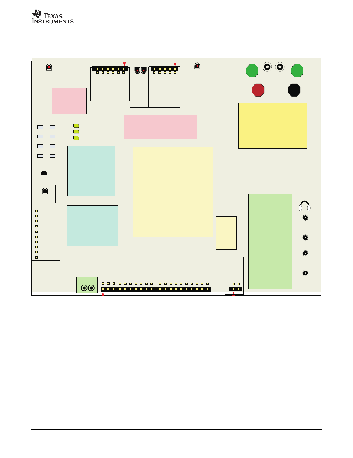
1.2 PCB Key Map
SPDIF I2S IN SPDIF SPDIF I2S SPDIF GND GND
I2S IN SDOUT2 IN OUT I2S OUT + 9 V -9 V
IR
Receiver
USB
IN
Control
IN
Analog Analog In Lineout
In 1 L & R 1 L&R to 20 L & R L & R
I2S Slave
I2S Master
Headphone
DACout1
DACout2
The physical structure for the TAS3208EVM is shown in Figure 1-3 .
PCB Key Map
Figure 1-3. TAS3208EVM Physical Structure
SLEU092 – February 2008 Overview 11
Submit Documentation Feedback
Page 12

Overview 12 SLEU092 – February 2008
Submit Documentation Feedback
Page 13

Chapter 2
SLEU092 – February 2008
Quick Setup Guide
This chapter describes the TAS3208EVM board in regards to power supplies and system interfaces. The
chapter provides information regarding handling and unpacking, absolute operating conditions, and a
description of the factory default switch and jumper configuration.
This chapter provides a step-by-step guide to configuring the TAS3208EVM for device evaluation.
Topic .................................................................................................. Page
2.1 Electrostatic Discharge (ESD) Warning ........................................ 14
2.2 Unpacking the EVM ................................................................... 14
2.3 Power-Supply Setup .................................................................. 14
2.4 Digital Audio Inputs/Outputs ...................................................... 14
2.5 Master/Slave Mode Operation ..................................................... 15
2.6 EVM Default Configuration ........................................................ 15
2.7 TAS3208 Software Installation .................................................... 15
SLEU092 – February 2008 Quick Setup Guide 13
Submit Documentation Feedback
Page 14

www.ti.com
Electrostatic Discharge (ESD) Warning
2.1 Electrostatic Discharge (ESD) Warning
Many of the components on the TAS3208EVM are susceptible to damage by ESD. Customers are
advised to observe proper ESD handling precautions when unpacking and handling the EVM, including
the use of a grounded wrist strap at an approved ESD workstation.
Failure to observe ESD handling procedures may result in damage to EVM
components.
2.2 Unpacking the EVM
Upon opening the TAS3208EVM package, check that the following items are included:
• TAS3208EVM board using one TAS3208DCP (1 pc.)
• 9-V ac-to-dc adapters (2 pc.)
• USB cable for connecting TAS3208EVM board to USB port on a PC for PurePath Studio™ software (1
pc.)
• PurePath CD-ROM containing data sheets, application reports, user's guides, gerber files, and PC
software tools (1 pc.)
If any of these items are missing, please contact the Texas Instruments Product Information Center to
inquire about a replacement.
CAUTION
2.3 Power-Supply Setup
The TAS3208EVM is powered via the ± 9-V terminals or the 9-V (center hot) power connectors, PJ1 and
PJ2. The TAS3208EVM generates a 5-V, –5-V, and 3.3-V supply that is fed to the TAS3208EVM.
1. Set the power supplies to 9 V and –9 V. Then turn off the supplies and connect them to the EVM.
2. Once the cables are connected, switch on the power supply. Current consumption should be less than
shown in Table 2-1 . If it is higher, switch off and double check the cabling.
2.4 Digital Audio Inputs/Outputs
Format optical TOSLINK input, OPTO1, or in I2S format on connector J1. The pinout this and the other
connectors is shown in Chapter 3 .
The SPDIF I2S IN input supplies signal to the TAS3208 SDIN1. When a valid lock is detected by the
DIR9001 SPDIF receiver, a blue SPDIF lock LED is lit.
The digital audio outputs can be to I2S or SPDIF format optical TOSLINK. The I2S output is provided on
connector J9. There are two SPDIF output options. One SPDIF output can be produced by the TAS3208
on SDOUT2. This is set by a TAS3208 I2C register configuration option. This output is available on
OPTO3. The other SPDIF output is SDOUT1, which is converted into SPDIF format by an external
encoder. This is output on OPTO4.
The TAS3208 has an optical SPDIF input from OPTO2. This is a pass-through-only connection to the
TAS3208 SDOUT2/SPDIF output on OPTO3.
Table 2-1. DAC8DIT2 Board Recommended Supply Voltages
Description Voltage Limitations Current Requirement
9 V 8.5 V to 9.5 V 0.3 A
–9 V –8.5 V to 9.4 V 0.1 A
Quick Setup Guide14 SLEU092 – February 2008
Submit Documentation Feedback
Page 15

www.ti.com
2.5 Master/Slave Mode Operation
The TAS3208EVM is delivered and configured to operate in clock master mode. However, the TAS3208
can be configured as a clock slave or master using JP3.
2.5.1 Master Mode
In master mode, the master clock (MCLK), SCLK< and LRCLK for the system are provided on J9. Data
can be input on the analog input and as I2S data on J1.
SPDIF I2S input from OPTO1 is not supported in master mode.
Data can be output from the I2S outputs on J9, SPDIF I2S output, OPTO4, and from SPDIF SDOUT2
when the SDOUT2 is configured for SPDIF output.
2.5.2 Slave Mode
In slave mode, data and clocks can be input in the SPDIF I2S IN, OPTO1, or the I2S input, J1. The SPDIF
input is selected automatically when the EVM detects a valid SPDIF signal on OPTO1. If the EVM does
not detect a valid SPDIF signal on OPTO1, the I2S inputs are used.
In slave mode, the TAS3208 ADC requires an external clock input from the I2S IN or the SPDIF I2S IN for
correct operation. The performance of the ADC is affected by the clock source jitter.
Data can be output from the I2S outputs on J9, SPDIF I2S output, OPTO4, and from SPDIF SDOUT2
when the SDOUT2 is configured for SPDIF output.
Master/Slave Mode Operation
Table 2-2. JP3 Clock Master/Slave Setting
Pin No. I2S Clock Mode
1, 2 Slave
2, 3 Master
2.6 EVM Default Configuration
The TAS3208 is placed into the default configuration by receiving a reset. The TAS3208 receives a reset
from the power-up circuitry by pressing the Reset button, or by receiving a reset signal through the USB
interface. Following the receipt of reset, the TAS3208EVM loads the contents of EEPROM2 and comes up
with Mute enabled, clock master mode enabled.
As described in this section, an example PurePath Studio GDE processing flow is supplied that configures
the TAS3208 to support an I2S digital PCM input, analog input, digital output, Line output, headphone
output, and TAS5601 power stage for both master and slave mode.
2.7 TAS3208 Software Installation
The TAS3208 is programmed and configured using PurePath Studio. PurePath Studio is composed of a
graphical development environment (GDE), integrated development environment (IDE), and component
publisher. The GDE permits the user to program the TAS3208 using predefined signal processing
components that are placed and connected graphically on the GDE pallet. PurePath Studio runs on a
Windows® XP computer.
The IDE is a software development environment that permits the user to construct and test the code for a
new GDE component.
The component publisher is used to create the component, define the component’s control interface and
the ways in which the component can be used.
PurePath Studio software is supplied on the TAS3208 Software CD-ROM. The latest version of PurePath
Studio is also available on the TI extranet to registered users.
SLEU092 – February 2008 Quick Setup Guide 15
Submit Documentation Feedback
Page 16

www.ti.com
TAS3208 Software Installation
Accessing the TI PurePath Studio extranet site
• Open a web browser and go to the following site and fill in the requested information:
http://iag.itg.ti.com/msa/
• There are two types of licenses:
– For those who are interested only in evaluating the tools, there is an evaluation license.
– For those who are interested in product development using PurePath Studio tools, there is a
production license. This is the software license that is needed to support the EVM.
Access to the extranet is available by using a browser to access my.ti.com and selecting Extranets. The
PurePath Studio software is contained under the link TAS3108-PurePath Studio.
Loading the PurePath Studio software suite
• From CD-ROM – Insert the TAS3208 Software CD-ROM. Open the TAS3208GDE directory and run
setup_PurePath_Studio_vx.xx.exe. Follow the instructions to compete the installation.
• From download – Save the installation file to temporary directory. Go to the temporary directory and
run setup_PurePath_Studio_vx.xx.exe. Follow the instructions to compete the installation.
• The CD-ROM also contains initialization files for master and slave EVM initialization and a simple
process flow that can be used to verify the TAS3208EVM operation.
• After PurePath Studio installation is complete, copy the contents of the CD-ROM TAS3208_Config
directory to C:\Program Files\Texas Instruments Inc\PurePath Studio\MyProcessFlows.
Using the TAS3208EVM
After completing the software installation, turn on power supplies and connect the USB cable to the
Input-USB board.
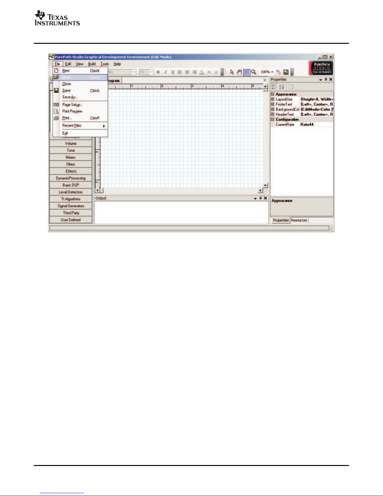
To start the GDE, go to the Start menu and select All Programs/Texas Instruments/PurePath Studio/Pure
Path Studio GDE.
The start-up of GDE takes a few seconds.
The TAS3208 requires an initialization configuration file to be loaded after a reset. This file configures the
TAS3208 for the EVM configuration, enables the analog outputs, and sets the clock master/slave mode.
Before loading or building a process flow, verify that an initialization file is specified in the Execute I2C
command file window. This window is found under Tools/I
16 Quick Setup Guide SLEU092 – February 2008
Figure 2-1. GDE Startup
2
C Command Tool.
Submit Documentation Feedback
Page 17

www.ti.com
If the EVM is to be operate in Master mode, select 3208EVM_init_master.cfg.
If the EVM is to be operate in Slave mode, select 3208EVM_init_slave.cfg.
TAS3208 Software Installation
Figure 2-2. Setting the I2C Initialization Sequence
SLEU092 – February 2008 Quick Setup Guide 17
Submit Documentation Feedback
Page 18

www.ti.com
TAS3208 Software Installation
Figure 2-3. Specifying the I2C Initialization Sequence
Then verify that the “Execute on reset” box is checked.
At this point, a process flow can be built using the TAS3208 application framework, the TAS3208 I/O
components, and the audio processing components.
Building and running a process flow
A good starting point is to load the predefined TAS3208 Test process flow.
This flow is loaded by selecting File/Open.
18 Quick Setup Guide SLEU092 – February 2008
Submit Documentation Feedback
Page 19
www.ti.com
TAS3208 Software Installation
Figure 2-4. Loading a Process Flow
Select TAS3208TEST.pfw (see Figure 2-5 ).
SLEU092 – February 2008 Quick Setup Guide 19
Submit Documentation Feedback
Page 20

www.ti.com
TAS3208 Software Installation
Figure 2-5. Loading a Process Flow (Part B)
This will load a process flow that streams a signal from either the ADC or SAP1 input to the DAC and SAP
outputs.
20 Quick Setup Guide SLEU092 – February 2008
Submit Documentation Feedback
Page 21

www.ti.com
TAS3208 Software Installation
Figure 2-6. GDE Test Process Flow
The input selection is performed by selecting the Stereo Multiplexer and changing the Mux Select Property
to StereoCh1, StereoCh2, StereoCh3, or StereoCh4.
To build this process flow and execute it on the EVM, select Build/Generate Code, then Build/Download
code, and finally Build/Run.
When the GDE transitions to run mode, the GDE resets the TAS3208EVM.
The reset restores the TAS3208 register to the default values.
The TAS3208 then loads the EEPROM image and the TAS3208_init_master/slave.cfg file.
At this point, the TAS3208EVM transitions to the run mode with the mute in the ON state.
For the TAS3208 to stream audio out of the DAC outputs, the mute must be returned to the inactive state.
This is done by pressing the mute button. The mute LED will be extinguished.
For more advanced use of the GDE, please refer to GDE online help, GDE release notes, and the
TAS3108 MCU Programmer’s Reference Guide..
SLEU092 – February 2008 Quick Setup Guide 21
Submit Documentation Feedback
Page 22

Quick Setup Guide22 SLEU092 – February 2008
Submit Documentation Feedback
Page 23
This chapter describes the TAS3208EVM board power supplies and system interfaces.
Topic .................................................................................................. Page
3.1 Control Interface (Control1), Input ............................................... 24
3.2 Digital Audio Interface, Input (J1) ................................................ 24
3.3 Analog Input (J6) ...................................................................... 25
3.4 Digital Audio Interface, Output (J9) ............................................. 25
3.5 RCA Connectors ...................................................................... 26
3.6 MSP430 Port Connector (J3) ....................................................... 27
3.7 I
2
S Master Slave Jumper (JP3) .................................................... 27
Chapter 3
SLEU092 – February 2008
System Interfaces
SLEU092 – February 2008 System Interfaces 23
Submit Documentation Feedback
Page 24

www.ti.com
Control Interface (Control1), Input
3.1 Control Interface (Control1), Input
This interface connects the TAS3208EVM board to an internal controller. This is a general-purpose
interface.
Pin No. Net-Name at Schematics Description
1 SDA I2C bidirectional data line
2 SCL I2C input clock line
3 GND Ground
4 3.3 V Power
5 GPIO1 General-purpose bidirectional I/O 1
6 GPIO2 General-purpose bidirectional I/O 2
7 RESETZ System reset (bidirectional). Activate MUTE before RESET for quiet reset.
8 MUTEZ
9 GPIO3 General-purpose bidirectional I/O 3
10 GPIO4 General-purpose bidirectional I/O 4
3.2 Digital Audio Interface, Input (J1)
The digital audio interface contains digital audio signal data (I2S), clocks, etc. Please see the TAS3208
Data Manual for signal timing and details not explained in this document.
Table 3-1. Control1 Pin Description
Ramp volume from any setting to noiseless soft mute. Mute can also be activated by
I2C.
Table 3-2. J1 Pin Description
Pin No. Net-Name at Schematics Description
1 GND Ground
2 MCLKin Master clock input
3 GND Ground
4 SCLKin I2S bit clock
5 GND Ground
6 LRCLKin I2S left-right clock
7 GND Ground
8 SDIN1 I2S data 1, channel 1 and 2
9 GND Ground
10 SDIN2 I2S data 2, channel 3 and 4
11 GND Ground
12 SDIN3 I2S data 3, channel 5 and 6
13 GND Ground
14 GND Ground
24 System Interfaces SLEU092 – February 2008
Submit Documentation Feedback
Page 25
www.ti.com
3.3 Analog Input (J6)
Pin No. Net-Name at Schematics Description
1 GND Ground
2 LineIn1L Line in left channel 1, also on RCA J5
3 GND Ground
4 LineIn1R Line in right channel 1, also on RCA J5
5 GND Ground
6 LineIn2L Line in left channel 2
7 GND Ground
8 LineIn2R Line in right channel 2
9 GND Ground
10 LineIn3L Line in left channel 3
11 GND Ground
12 LineIn3R Line in right channel 3
13 GND Ground
14 LineIn4L Line in left channel 4
15 GND Ground
16 LineIn4R Line in right channel 4
17 GND Ground
18 LineIn5L Line in left channel 5
19 GND Ground
20 LineIn5R Line in right channel 5
23 GND Ground
22 LineIn6L Line in left channel 6
23 GND Ground
24 LineIn6R Line in right channel 6
25 GND Ground
26 LineIn7L Line in left channel 7
27 GND Ground
28 LineIn7R Line in right channel 7
29 GND Ground
30 LineIn8L Line in left channel 8
31 GND Ground
32 LineIn8R Line in right channel 8
33 GND Ground
34 LineIn9L Line in left channel 9
35 GND Ground
36 LineIn9R Line in right channel 9
37 GND Ground
38 LineIn10L Line in left channel 10
39 GND Ground
40 LineIn10R Line in right channel 10
Analog Input (J6)
Table 3-3. J6 Pin Description
3.4 Digital Audio Interface, Output (J9)
The digital audio interface contains digital audio signal data (I2S), clocks, etc. Please see the TAS3208
Data Manual for signal timing and details not explained in this document.
SLEU092 – February 2008 System Interfaces 25
Submit Documentation Feedback
Page 26

www.ti.com
RCA Connectors
Table 3-4. J9 Pin Description
Pin No. Net-Name at Schematics Description
1 GND Ground
2 MCLKO Master clock output
3 GND Ground
4 SCLKout I2S bit clock
5 GND Ground
6 LRCLKout I2S left-right clock
7 GND Ground
8 SDOUT1 I2S data 1, channel 1 and 2
9 GND Ground
10 SDOUT2 I2S data 2, channel 3 and 4
3.5 RCA Connectors
Table 3-5. RCA Connectors Pin Description
Pin No. Net-Name at Schematics Description
1 Signal Channel input/output – tip
2 AGND Analog ground – sleave
26 System Interfaces SLEU092 – February 2008
Submit Documentation Feedback
Page 27

www.ti.com
3.6 MSP430 Port Connector (J3)
3
2
1
Pin No. Net-Name at Schematics Description
1 TDO Test data out
2
3 TCLK Test clock
4 3.3V 3.3 V power supply
5 TMS Test mode select
6
7 TCK Test clock
8 TEST Test
9 GND GND
10
11 RESET Reset
12
13
14
3.7 I2S Master Slave Jumper (JP3)
MSP430 Port Connector (J3)
Table 3-6. J3 Pin Description
PCB Connector (Top View)
Table 3-7. JP3 Pin Description
Pin No. Description
1, 2 I2S slave
2, 3 I2S master
SLEU092 – February 2008 System Interfaces 27
Submit Documentation Feedback
Page 28

System Interfaces28 SLEU092 – February 2008
Submit Documentation Feedback
Page 29

This chapter describes the MSP430 programming.
Topic .................................................................................................. Page
4.1 Example of MSP430 Programming .............................................. 30
Chapter 4
SLEU092 – February 2008
MSP430 Programming
SLEU092 – February 2008 MSP430 Programming 29
Submit Documentation Feedback
Page 30

www.ti.com
Digital
Input(s)
Analog
Input
Func
#1
Func
#2
Func
#3
Vol
PWM
Output
Stereo
Splitter
Stereo
Mux(s) #2
I2C Addr 193 ( 0xC1)
1= Function LED8 ON
2= Bypass
Switc h S5 toggles
between Function
and Bypass
Stereo
Splitter
Stereo
Mux(s) #3
I2C Addr 194 ( 0xC2)
1= Function LED9 ON
2= Bypass
Switc h S6 toggles
between Function
and Bypass
Stereo
Mux(s) #1
I2C Addr 192 (0xC0)
1= Analog L ED7 ON
2= Digital
Switch S4 t oggles
between Function
and Bypass
Stereo
Splitter
Stereo
Mux(s) #4
I2C Addr 195 ( 0xC3)
1= Function LED10 ON
2= Bypass
Switc h S7 toggles
between Function
and Bypass
Stereo Signal path
Optional Stereo Signal path
VOLUME
I2C Addr 198 ( 0xC6)
1= Function
2= Bypass
Switch S2 I ncreases Vol
Switch S3 D ecreases Vol
I2C Addresses
196 (0xC4) Reserved
197 (0xC5) Reserved
199 (0xC7) Reserved
Example of MSP430 Programming
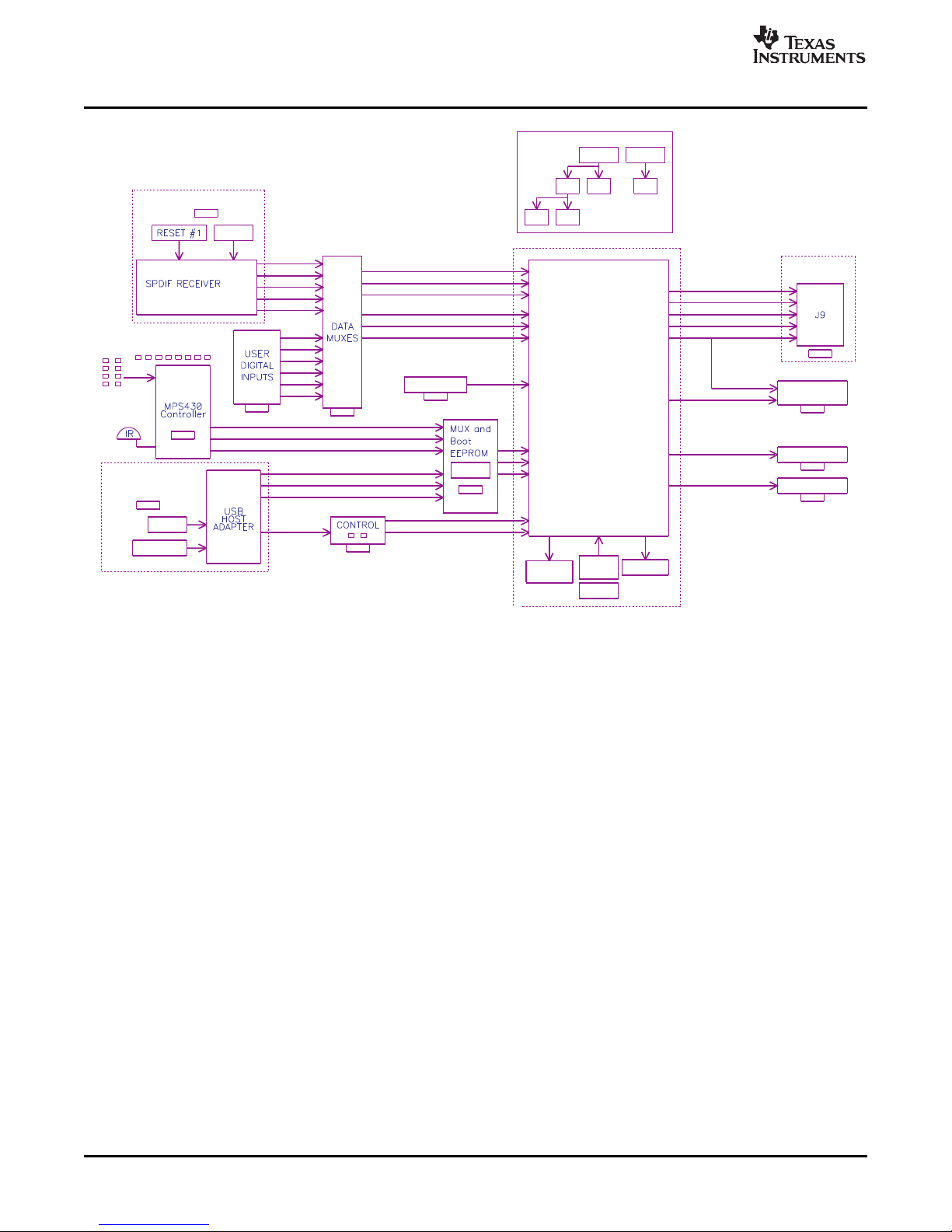
4.1 Example of MSP430 Programming
The MSP430 can be programmed to provide TAS3308 and power-stage initialization and control. During
initialization, the MSP430 should wait for the TAS3308 to complete booting from EEPROM. It then sends
an initialization sequence to the TAS3308. At this point, the MSP430 sends I2C commands to the
TAS3308 when it receives an input from one of the onboard switches or the IR remote control.
The microcontroller has eight circuit-board pushbuttons and LEDs to support user control functions.
These controls can be programmed to provide functions and indications, such as:
• Select analog/digital source
• Function 1 (surround effect) on/off
• Function 2 (EQ) on/off
• Function 3 (DRC) on/off
• Volume up/volume down
30 MSP430 Programming SLEU092 – February 2008
Figure 4-1. Example MSP430 Control
Submit Documentation Feedback
Page 31

IMPORTANT NOTICE
Texas Instruments Incorporated and its subsidiaries (TI) reserve the right to make corrections, modifications, enhancements, improvements,
and other changes to its products and services at any time and to discontinue any product or service without notice. Customers should
obtain the latest relevant information before placing orders and should verify that such information is current and complete. All products are
sold subject to TI’s terms and conditions of sale supplied at the time of order acknowledgment.
TI warrants performance of its hardware products to the specifications applicable at the time of sale in accordance with TI’s standard
warranty. Testing and other quality control techniques are used to the extent TI deems necessary to support this warranty. Except where
mandated by government requirements, testing of all parameters of each product is not necessarily performed.
TI assumes no liability for applications assistance or customer product design. Customers are responsible for their products and
applications using TI components. To minimize the risks associated with customer products and applications, customers should provide
adequate design and operating safeguards.
TI does not warrant or represent that any license, either express or implied, is granted under any TI patent right, copyright, mask work right,
or other TI intellectual property right relating to any combination, machine, or process in which TI products or services are used. Information
published by TI regarding third-party products or services does not constitute a license from TI to use such products or services or a
warranty or endorsement thereof. Use of such information may require a license from a third party under the patents or other intellectual
property of the third party, or a license from TI under the patents or other intellectual property of TI.
Reproduction of TI information in TI data books or data sheets is permissible only if reproduction is without alteration and is accompanied
by all associated warranties, conditions, limitations, and notices. Reproduction of this information with alteration is an unfair and deceptive
business practice. TI is not responsible or liable for such altered documentation. Information of third parties may be subject to additional
restrictions.
Resale of TI products or services with statements different from or beyond the parameters stated by TI for that product or service voids all
express and any implied warranties for the associated TI product or service and is an unfair and deceptive business practice. TI is not
responsible or liable for any such statements.
TI products are not authorized for use in safety-critical applications (such as life support) where a failure of the TI product would reasonably
be expected to cause severe personal injury or death, unless officers of the parties have executed an agreement specifically governing
such use. Buyers represent that they have all necessary expertise in the safety and regulatory ramifications of their applications, and
acknowledge and agree that they are solely responsible for all legal, regulatory and safety-related requirements concerning their products
and any use of TI products in such safety-critical applications, notwithstanding any applications-related information or support that may be
provided by TI. Further, Buyers must fully indemnify TI and its representatives against any damages arising out of the use of TI products in
such safety-critical applications.
TI products are neither designed nor intended for use in military/aerospace applications or environments unless the TI products are
specifically designated by TI as military-grade or "enhanced plastic." Only products designated by TI as military-grade meet military
specifications. Buyers acknowledge and agree that any such use of TI products which TI has not designated as military-grade is solely at
the Buyer's risk, and that they are solely responsible for compliance with all legal and regulatory requirements in connection with such use.
TI products are neither designed nor intended for use in automotive applications or environments unless the specific TI products are
designated by TI as compliant with ISO/TS 16949 requirements. Buyers acknowledge and agree that, if they use any non-designated
products in automotive applications, TI will not be responsible for any failure to meet such requirements.
Following are URLs where you can obtain information on other Texas Instruments products and application solutions:
Products Applications
Amplifiers amplifier.ti.com Audio www.ti.com/audio
Data Converters dataconverter.ti.com Automotive www.ti.com/automotive
DSP dsp.ti.com Broadband www.ti.com/broadband
Clocks and Timers www.ti.com/clocks Digital Control www.ti.com/digitalcontrol
Interface interface.ti.com Medical www.ti.com/medical
Logic logic.ti.com Military www.ti.com/military
Power Mgmt power.ti.com Optical Networking www.ti.com/opticalnetwork
Microcontrollers microcontroller.ti.com Security www.ti.com/security
RFID www.ti-rfid.com Telephony www.ti.com/telephony
RF/IF and ZigBee® Solutions www.ti.com/lprf Video & Imaging www.ti.com/video
Mailing Address: Texas Instruments, Post Office Box 655303, Dallas, Texas 75265
Copyright © 2008, Texas Instruments Incorporated
Wireless www.ti.com/wireless
Page 32

Mouser Electronics
Authorized Distributor
Click to View Pricing, Inventory, Delivery & Lifecycle Information:
Texas Instruments:
TAS3208EVM
 Loading...