

Page 1

Stellaris® MDL-BDC24 Brushed DC Motor
Control Module
Getting Started Guide
MDL-BDC24-GSG-04 Copyright © 2009–2011 Texas Instruments
Page 2

Copyright
Copyright © 2009–2011 Texas Instruments, Inc. All rights reserved. Stellaris and StellarisWare are registered trademarks of Texas Instruments.
ARM and Thumb are registered trademarks, and Cortex is a trademark of ARM Limited. Other names and brands may be claimed as the property
of others.
Texas Instruments
108 Wild Basin, Suite 350
Austin, TX 78746
http://www.ti.com/stellaris
2 January 5, 2011
Page 3

Stellaris® Brushed DC Motor Control User’s Manual
Table of Contents
Chapter 1: Introduction to Jaguar................................................................................................................... 5
Features.............................................................................................................................................................. 7
Differences between the MDL-BDC and MDL-BDC24 ....................................................................................... 8
Warnings............................................................................................................................................................. 8
Chapter 2: General Operation.......................................................................................................................... 9
Operating Modes .............................................................................................................................................. 10
Fault Conditions ............................................................................................................................................ 10
Coast/Brake Jumper ..................................................................................................................................... 11
Power and Motor Wiring ............................................................................................................................... 11
Chapter 3: Servo/PWM-based Control.......................................................................................................... 13
Servo-style PWM Speed Control Input ............................................................................................................. 13
Calibrating the PWM Input ............................................................................................................................ 13
Chapter 4: Introduction to Network-Based Control.....................................................................................15
Network Security and System Safety ............................................................................................................... 15
Trusted Mode (FIRST Robotics Competition feature) ...................................................................................... 15
Chapter 5: Operation using the RS232 Interface.........................................................................................17
BDC-COMM Application Overview ................................................................................................................... 17
Chapter 6: Firmware Update Using BDC-COMM ......... ................................................................................19
Important Information........................................................................................................................................ 19
Step 1: Hardware Setup................................................................................................................................ 19
Step 2: Run BDC-COMM.............................................................................................................................. 20
Step 3: Assign Unique CAN ID ..................................................................................................................... 20
Step 4: Update Firmware .............................................................................................................................. 20
Chapter 7: Closed-Loop Control Options.....................................................................................................21
Wiring................................................................................................................................................................ 21
Constant Current Control.................................................................................................................................. 22
Position Control using an Encoder ................................................................................................................... 22
Position Control Using a Potentiometer............................................................................................................ 23
Speed Control................................................................................................................................................... 23
Chapter 8: Operation Using the CAN Interface............................................................................................ 25
CAN Overview .................................................................................................................................................. 25
CAN IDs............................................................................................................................................................ 25
CAN Network .................................................................................................................................................... 25
Control Options for Networked Jaguar Modules ............................................................................................... 26
Appendix A: Jaguar Communication Cables...............................................................................................29
CAN Terminator................................................................................................................................................ 29
CAN Cable........................................................................................................................................................ 29
CAN Cable Assembly ................................................................................................................................... 30
CAN Cable Pin Assignments ........................................................................................................................ 30
RS232 Cable .................................................................................................................................................... 30
RS232 Cable Assembly ................................................................................................................................ 30
RS232 Cable Pin Assignments..................................................................................................................... 31
External References ......................................................................................................................................... 31
January 5, 2011 3
Page 4

4 January 5, 2011
Page 5

CHAPTER 1
Introduction to Jaguar
Texas Instruments presents the next generation FIRST Robotics Competition (FRC) motor
controller: the MDL-BDC24 brushed DC motor control (also known as Black Jaguar). The
MDL-BDC24 builds on the success of the first-generation MDL-BDC (Gray Jaguar) by adding an
RS232-to-CAN gateway and enhanced electrical performance. Designed specifically for the FRC
competition, the MDL-BDC and MDL-BDC24 modules facilitate the design of complex robots
within the short six-week FRC build period.
This document provides a complete description of how to use Jaguar in both Networked and Servo
control modes. Information applies to both the MDL-BDC and MDL-BDC24 models except where
noted. Additional information can be found in the MDL-BDC and MDL-BDC24 data sheets, as well
as in related application notes.
Figure 1-1. Next Generation Brushed DC Motor Control Module, MDL-BDC24
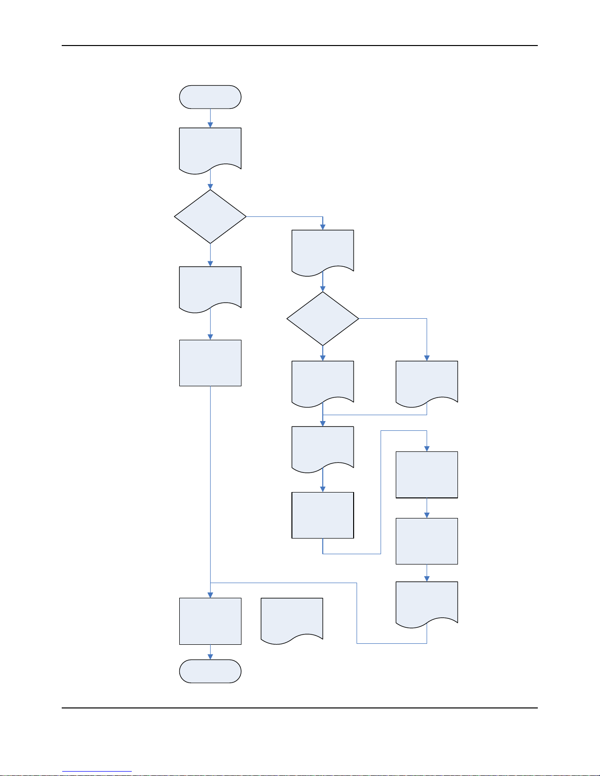
The flowchart in Figure 1-2 provides an overview of the process of developing with the MDL-BDC
and MDL-BDC24 modules. We suggest checking off each step as it is completed.
January 5, 2011 5
Page 6
Getting Started
with Jaguar
Connect:
- Servo cable
- Power cable
- Motor cable
Decision:
Control using
Servo/PWM or
Network?
Read Jaguar GSG
Introduction and
General Operation
Chapters
Servo/PWM
Read Jaguar GSG
Servo/PWM
Control
Chapter
Ready to Run!
Read Jaguar GSG
Introduction to
Network Control
Chapter
Decision :
CAN Interface
Method
Network
Read 3rd Party
CAN Bridge
documentation
3rd Party CAN Interface
Assemble and
connect cables:
- RS232/CAN
- Power
Read Jaguar GSG
Operation using
RS232 Chapter
Read Jaguar GSG
Firmware Update
using BDC-COMM
Chapter
Update firmware in
each Jaguar
Connect to cRIO-
based FRC control
system
Black Jaguar Bridge
Read Jaguar GSG
Operation using
the CAN Interfac e
Chapter
Appendix A
Jaguar Cable
Assemblie s
Assign CAN ID
(ID Value > 1)
Introduction to Jaguar
Figure 1-2. MDL-BDC24 Development Process
6 January 5, 2011
Page 7

Features
The Stellaris® Brushed DC Motor Control Module with CAN (MDL-BDC24) offers a variable speed
control for 12 V and 24 V brushed DC motors at up to 40 A continuous current. The motor control
module includes high performance Controller Area Network (CAN) connectivity and a rich set of
control options and sensor interfaces, including analog and quadrature encoder interfaces. The
high-frequency PWM on the MDL-BDC24 enables DC motors to run smoothly and quietly over a
wide speed range. The module uses highly optimized software and a powerful 32-bit Stellaris®
microcontroller to implement open-loop speed control as well as closed-loop control of speed,
position, or motor current.
The MDL-BDC24 provides the following features:
Quiet control of brushed DC motors
Three options for Speed control
CAN communication
Getting Started Guide
– 15 kHz PWM frequency
– Industry-standard R-C servo type (PWM) interface
– Controller Area Network (CAN) interface
– RS232 serial interface
– Multicast shared serial bus for connecting systems in electromagnetically noisy
environments
– 1M bits/s bit rate
– CAN protocol version 2.0 B
– Full configurability of module options
– Real-time monitoring of current, voltage, speed, and other parameters
– Firmware update
RS232 serial communication
– Bridges RS232 port to a CAN network
– Directly interfaces to a PC serial port or National Instruments cRIO
Status LED indicates Run, Direction, and Fault conditions
Motor brake/coast selector
Limit switch inputs for forward and reverse directions
Quadrature encoder input (QEI)
– Index input
– 5 V supply output to encoder
Analog input
– Accepts 10 kΩ potentiometer or 0-3 V input
Screw terminals for all power wiring
Headers (0.1 inch pitch) for all control signals
January 5, 2011 7
Page 8
Introduction to Jaguar
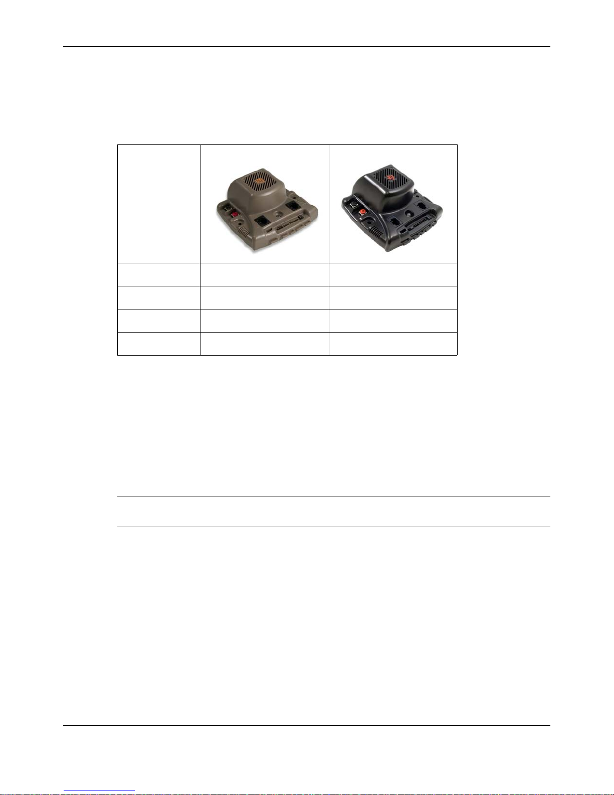
Differences between the MDL-BDC and MDL-BDC24
First generation Jaguar motor controls (MDL-BDC) have similar capabilities to the second
generation Jaguar (MDL-BDC24). Functional differences are summarized in Table 1-1.
Table 1-1. MDL-BDC and MDL-BDC24 Differences
MDL-BDC (Gray) MDL-BDC24 (Black)
Feature
Part Number
Voltage Range
RS232C Port
Terminal Screws
a. Captive terminal screws should not be removed because metal debris can be created.
b. Non-captive screws are safe to remove and are compatible with ring-terminal use.
Internally, the MDL-BDC24 is a completely new design that makes use of switching converters and
synchronous rectification to improve overall energy efficiency.
Software should be updated to the latest version to ensure that all capabilities of the MDL-BDC or
MDL-BDC24 module are enabled and functional.
Warnings
WARNING – Be aware of the following warnings. Failure to heed warnings can result in damage
to the module or invalidation of the module warranty.
Mount the Jaguar module so that the vents in the top and sides of the unit are not restricted in
any way. Maintain a clearance of at least ½ inch between modules.
MDL-BDC MDL-BDC24
6–13 V 6–30 V
No Yes
Captive – Do not remove
a
Loose – Okay to remove
b
Reverse wiring is unprotected; doing so voids the Jaguar module's warranty.
Do not exceed the absolute maximum supply voltage (30 V
MDL-BDC). Doing so causes permanent damage to the module.
Protect Jaguar from all situations where debris could enter through ventilation slots or
connector openings.
8 January 5, 2011
for MDL-BDC24, 13 V for
DC
Page 9
Motor
Out
(–) Motor
(+) Mo tor
(–) In
(+) In
From Power
Distributio n
Module
M ot or outpu t is not pr ot e ct e d
against short-circuits.
User Switch
Use hooks to prevent
wires shaking loose
Maintain 0.5" cl earance
around all vents
Stat us LE D
Mounting holes
3.50" centers
Motor coast/brake jumper
Ma in ta in 0. 5" cl e ar an ce
around all vents
For power wiring use
12 A W G W ire w it h #6 ri ng
or spade terminals
CAN P ort
RS232/CAN Port
Anal og input (0-3V)
Encoder Input
Limit switch inputs
CHAPTER 2
General Operation
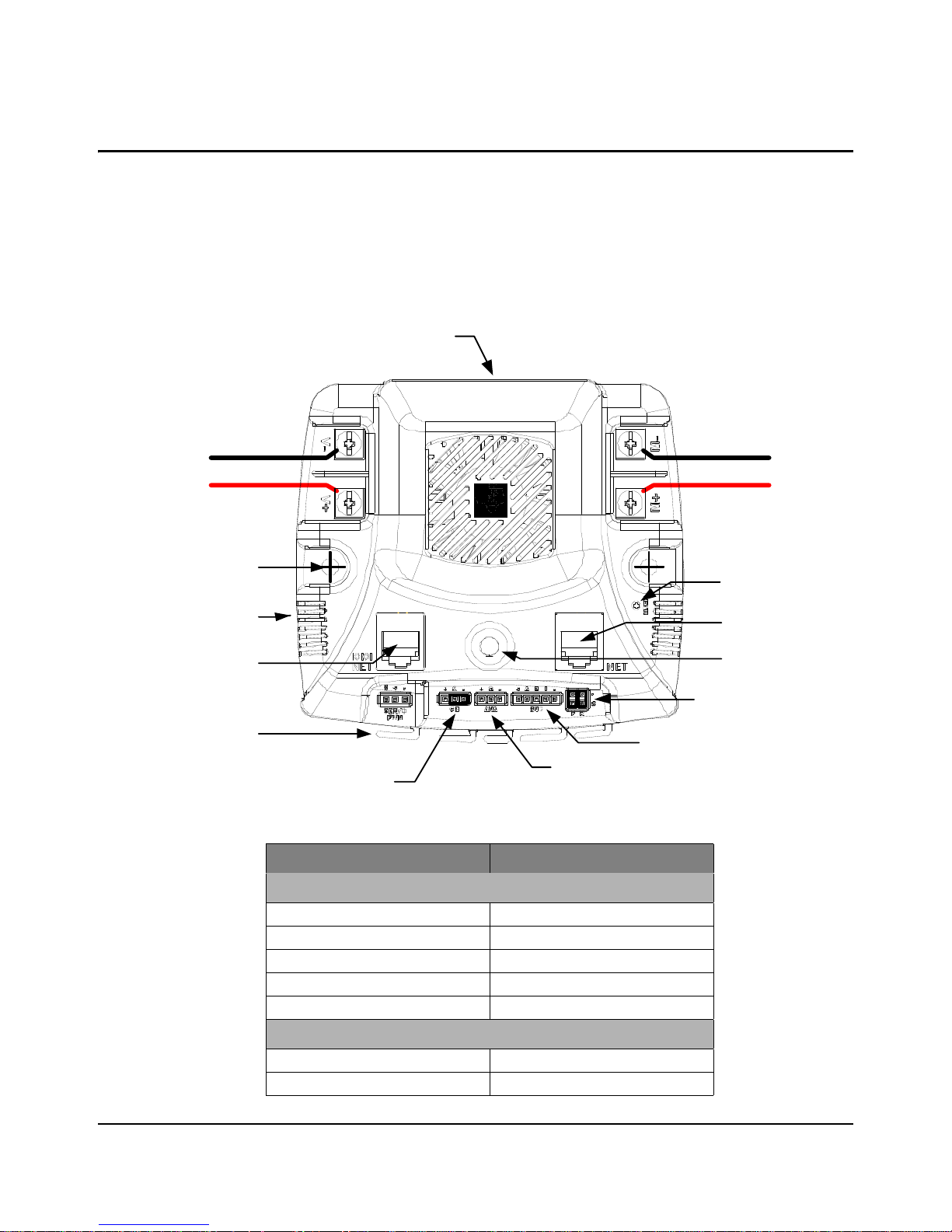
This chapter describes the general operation of the MDL-BDC24 motor control module. Figure 2-1
shows the key features of the MDL-BDC24 motor control. Table 2-1 provides a key to the status
LED.
Figure 2-1. MDL-BDC24 Key Features
January 5, 2011 9
Table 2-1.
Table 2-2. Status LED
Normal Operating Conditions
Solid Yellow Neutral (speed set to 0)
Fast Flashing Green Forward
Fast Flashing Red Reverse
Solid Green Full-speed forward
Solid Red Full-speed reverse
Fault Conditions
Slow Flashing Yellow Loss of servo or Network link
Fast Flashing Yellow Invalid CAN ID
LED State Module Status
Page 10
General Operation
Table 2-2. Status LED (Continued)
Slow Flashing Red Fault condition
Calibration Conditions
Fast Flashing Red and Green Calibration mode active
Fast Flashing Red and Yellow Calibration mode failure
Fast Flashing Green and Yellow Calibration mode success
Slow Flashing Red and Green
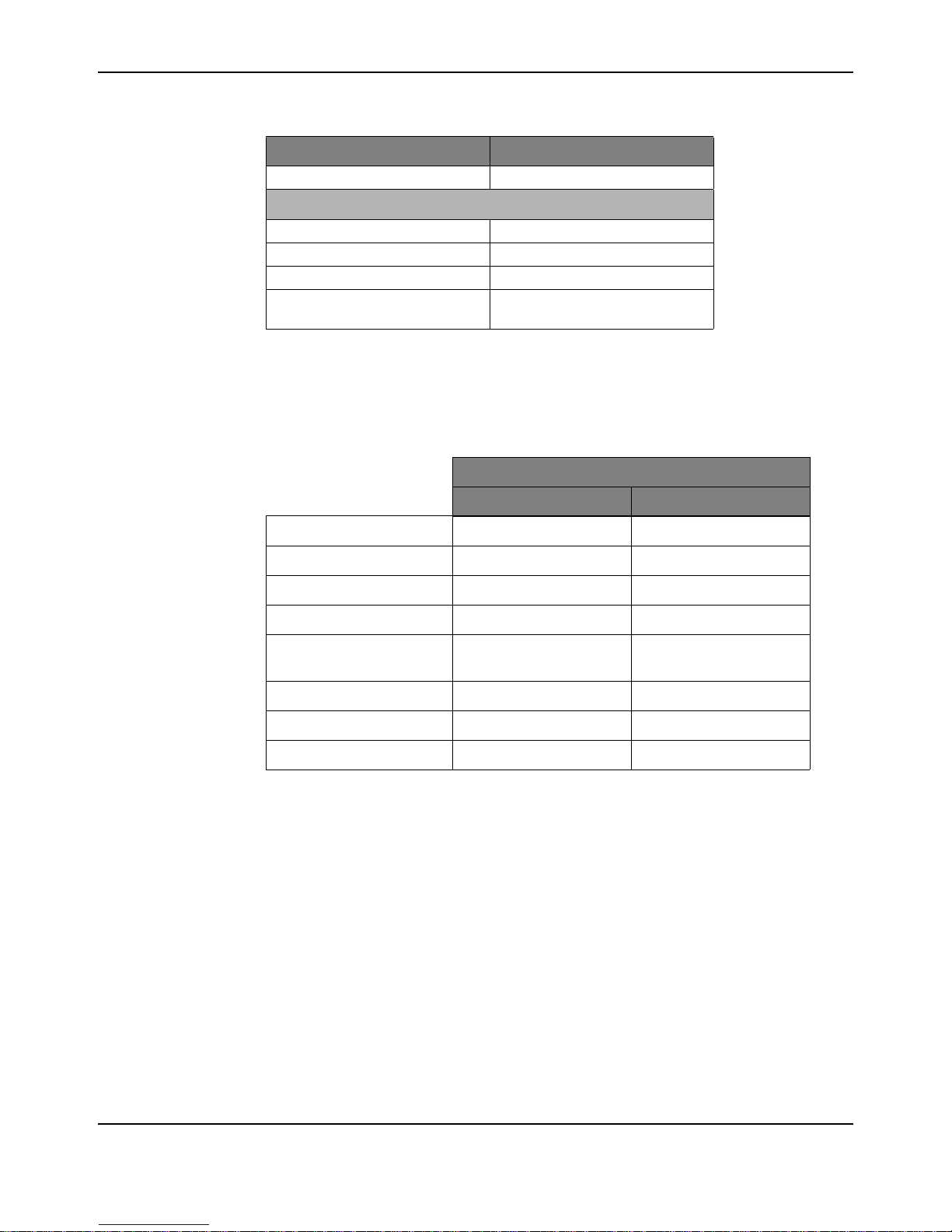
Operating Modes
The MDL-BDC24 can be controlled using either the Servo-style PWM Input or the CAN interface.
Table 2-3 compares the capabilities of each control method.
Table 2-3.
Table 2-4. Control Method Comparison
LED State Module Status
Calibration mode reset to factory
default settings success
Control Method
Servo-Style PWM input CAN/RS232C Interface
Jaguar supports the simultaneous use of CAN for monitoring and the Servo-style input for speed.
Fault Conditions
A slow flashing Red LED indicates that the MDL-BDC24 detected one of the following fault
conditions:
Power supply under-voltage
Over temperature
Speed Control Yes Yes
Analog Position Control No Yes
Encoder Position Control No Yes
Configurable Parameters No Yes
Voltage, Current
Measurement
Limit Switches Yes Yes
Coast/Brake Feature Yes Yes
Firmware Update No Yes
a. By default, the jumper sets coast/brake. Network commands can over-ride the jumper
setting.
No Yes
a
Over current
Limit switch activated in the current direction of motion
When a fault condition occurs, the motor shuts down and the LED indicates a fault state during the
fault condition and for 3 seconds after the fault cause is cleared (except for the limit switch fault,
10 January 5, 2011
Page 11

which is cleared instantly). A slow flashing Yellow LED indicates that the MDL-BDC24 is not
receiving a valid control signal.
Coast/Brake Jumper
The coast/brake signal controls the dynamics of the drive signal to the motor. When set to brake,
the MDL-BDC24 is able to achieve greater deceleration and holding torque because it decays
regenerative current from the motor.
The coast/brake signal can be set with a jumper or controlled by a signal from a digital source. A
single wire connected to the center (S) pin, is recommended. Do not connect to the + pin (+3.3 V)
of this connector as any mis-wiring could damage the MDL-BDC24.
The coast/brake jumper setting can be overwritten when using the CAN/RS232 interface.
Power and Motor Wiring
The Overview diagram (Figure 1-2 on page 6) shows motor and power connections to the
MDL-BDC24. For power wiring, use 10-12 AWG wire terminated with #6 ring or spade terminals.
The control is not protected against reverse polarity or short-circuits.
Getting Started Guide
January 5, 2011 11
Page 12

General Operation
12 January 5, 2011
Page 13

Motor
Out
(–) Motor
(+) Motor
P W M speed
signal from
Di g it al Sid ecar
+5V
GN D
Reverse direction
switch(es)
Normally-closed
Li mi t switches
(–) In
(+) In
From Power
Distribution
Module
User Switch
PWM
+5V is o ptional (no internal connection)
Status LED
Forward direction
swi tch(e s)
Ins tall jumpers if
limit switc hes are
not used.
CHAPTER 3
Servo/PWM-based Control
The MDL-BDC and MDL-BDC24 both support speed and direction control through a servo-style
PWM input. Figure 3-1 shows the servo-wiring details.
Figure 3-1. Wiring for Servo-style PWM Control
Servo-style PWM Speed Control Input
Calibrating the PWM Input
January 5, 2011 13
The servo PWM input controls motor speed and direction. The digital signal must meet the timing
and voltage requirements listed in the MDL-BDC24 specifications. The center pin (+) has no
internal connection. Because the signal is optically isolated, both the signal (S) and GND (-) pins
must be connected to the signal source.
The servo-style PWM input is optically isolated. All other control inputs are non-isolated and are
referenced to the power supply (-).
To accommodate variation in the timing of the supplied signal, Jaguar has a calibrate feature that
sets new values for full-forward, full-reverse and points in between. Calibration is normally only
required in applications where the PWM source has uncertainties due to analog radio links or other
variables. Direct digital sources are unlikely to require calibration.
Page 14

Servo/PWM-based Control
To calibrate the servo-style PWM input for a specific range, connect a PWM source, then:
1. Hold down the USER switch with a straightened paperclip for 5 seconds.
2. The LED flashes Red and Green to indicate Calibration mode.
3. Instruct the controller to send a full-forward signal for one or more seconds.
4. Instruct the controller to send a full-reverse signal for one or more seconds.
5. The LED flashes Green and Yellow quickly to indicate a successful calibration.
The MDL-BDC24 samples these signals and centers the speed range and neutral position
between these limits. A calibration failure signals if an out-of-range signal is detected. This
condition is indicated by flashing the LED Red and Yellow.
14 January 5, 2011
Page 15

CHAPTER 4
Introduction to Network-Based Control
Both MDL-BDC and MDL-BDC24 support CAN-based control, configuration and firmware
updates. MDL-BDC24 also supports the same command set over RS232.
Network Security and System Safety
The factory default network protocol allows for very flexible control networks with all commands
being accepted and executed without restriction. However, a vulnerability is that faulty software
has the potential to send errant messages. To address the possibility that motors could run when
they are not supposed to, a special set of trusted commands have been added. This capability is
supported in an FRC-specific firmware update. All MDL-BDC and MDL-BDC24 modules must
have updated firmware if they are to be used with CAN or RS232 communication in an FRC
competition.
Trusted Mode (FIRST Robotics Competition feature)
Each MDL-BDC and MDL-BDC24 module expects to see a trusted message from the Host every
100 ms. If a trusted message is not received, the MDL-BDC and MDL-BDC24 module shut down
the motor output until trusted communication is restored.
Trusted communication relies on a proprietary protocol that defines a dynamic message token,
known only to the host driver and a specific MDL-BDC or MDL-BDC24 module.
Non-FIRST users should use the factory-default firmware (available in source form) which does
not implement trusted communication.
January 5, 2011 15
Page 16

Introduction to Network-Based Control
16 January 5, 2011
Page 17

Motor
Out
(–) Motor
(+) Motor
(–) In
(+) In
From Power
Distribution
Module
DB9 Adapter
Connect to
Host Controller
(PC, cRIO)
To other CAN
Devices
Black Jaguar bridges
RS232 to CAN
CHAPTER 5
Operation using the RS232 Interface
The MDL-BDC24 supports a full set of network control and configuration functions over a standard
RS232C serial interface. The command protocol is essentially the same as the protocol used on
the CAN interface allowing the MDL-BDC24 to automatically bridge all commands between the
RS232 and CAN interfaces.
RS232 signals are implemented on the left-side NET connector, which has a special IOIOI
annotation as shown in Figure 5-1.
Figure 5-1. MDL-BDC24 Bridges for RS232 to CAN
See Appendix A, “Jaguar Communication Cables,” on page 29 for details of the RS232 cable
assembly. The recommended DB9 adapter design contains an integrated CAN terminator.
BDC-COMM Application Overview
BDC-COMM is a Windows application for configuring and controlling a Jaguar network using a PC’s
RS232 serial port. It is also a convenient tool for performing firmware updates. BDC-COMM requires
the use of an
MDL-BDC24 to bridge RS232 to CAN. Figure 5-2 on page 18 shows the main GUI
window of the BDC-COMM application.
January 5, 2011 17
Page 18

Operation using the RS232 Interface
Figure 5-2. BDC-COMM GUI Main Window
18 January 5, 2011
Page 19

Connect to PC
Seri al Port
Connec t to PC
Serial Port
JaguarBlack Jaguar
Black Jaguar
Ter mi nator
Ter minator
Firmware Update
Update Firmware
on this Jaguar
RS232/CAN Bridge
Firmware Update
CHAPTER 6
Firmware Update Using BDC-COMM
Firmware update capability allows Texas Instruments to provide new software, in binary format,
that contains feature enhancements and bug fixes.
Special firmware releases have been created for FRC 2010. Both MDL-BDC and MDL-BDC24
have firmware updates available. This firmware update must be installed prior to using RS232 or
CAN-based control. Firmware update is optional for Servo/PWM control.
Firmware update requires RS232 and CAN cables, at least one MDL-BDC24, the binary file, a PC
with an RS232 port, and a 12 V power source.
The BDC-COMM Application User’s Guide contains additional detail on using the tool for firmware
update as well as other configuration and control functions.
Important Information
Observe the following precautions when updating firmware:
We strongly recommend connecting only one Jaguar to the network at a time. The exception is
when updating a single first generation (MDL-BDC) Jaguar. To update an MDL-BDC Jaguar,
add only theMDL-BDC24 that is being used as the RS232-to-CAN bridge.
Use the correct binary file. For first generation MDL-BDC modules, the file is named
QS-BDC.bin. For second generation MDL-BDC24 modules (black), the file is named
QS-BDC24.bin
Step 1: Hardware Setup
Connect an MDL-BDC24 (black) to a PC following the information in Chapter 5, “Operation
using the RS232 Interface” on page 17.
If a first-generation (MDL-BDC) Jaguar (gray) requires firmware update, then connect it to the
MDL-BDC24 (see Figure 6-1).
Apply power. The LED on the Jaguar(s) flash yellow indicating loss-of-link.
Figure 6-1. Valid Conf igurations for Firmware Update
January 5, 2011 19
Page 20

Firmware Update Using BDC-COMM
Step 2: Run BDC-COMM
Run BDC-COMM.EXE.
The LED on the Jaguar(s) should now be solid yellow indicating a valid network link. If the LED
is not solid yellow, check all network connections as well as the BDC-COMM Com Port setting.
A valid link must be established before proceeding to the next step.
Step 3: Assign Unique CAN ID
If two modules are connected, each must have a unique CAN ID. The factory default CAN ID
is 1.
Assign the Jaguar modules the ID > 1 so that new Jaguar modules from the factory do not
operate on your robot.
Using the BDC-COMM application, select the System tab and enter a new ID (a unique
number from 2..63).
Click “Assign.” The LED on the module(s) starts flashing green.
Press the USER button on the module that is to receive the new ID. This must be done within
5 seconds or the operation times out.
The module’s LED blinks the number of times that corresponds to the ID if assignment was
successful (for example, if you assign the unique ID number of 5, the LED blinks five times).
A fast-flashing yellow LED indicates an invalid CAN ID. This can occur if an attempt is made to
reassign an ID that is already in use.
Step 4: Update Firmware
A valid link must be established before proceeding. Ensure that the LED indicates solid yellow.
It might be necessary to reconnect to the CAN network to synchronize the trusted link.
Select the board ID that you want to update using the “Board ID” menu.
Select File > Update Firmware from the top menu bar.
Browse to locate the appropriate binary file:
– The MDL-BDC24 (black) uses the qs-bdc24.bin file.
– The MDL-BDC (gray) uses the qs-bdc.bin file.
Click OK and then click Update.
A progress bar displays the firmware update progress.
When the firmware update completes, reconnect bdc-comm to the network to re-establish a
link.
The System tab in BDC-COMM displays the firmware version.
20 January 5, 2011
Page 21

CHAPTER 7
Closed-Loop Control Options
A network-controlled Jaguar supports several types of closed-loop control through an internal PID
controller.
Constant-current control
Position control using an encoder
Position control using a potentiometer
Speed control
Only one mode can be used at a time.
For each control mode, refer to API, VI, or tool documentation for information on which commands
to use for configuration.
Wiring
All closed-loop mode, except for constant-current control, require an external sensor. Figure 7-1
shows an advanced wiring configuration using the CAN interface. The diagram shows wiring for
position sensing using both a position potentiometer and a quadrature encoder. Although two
sensor types are shown, the MDL-BDC software supports control and monitoring of only one
sensor at a time.
January 5, 2011 21
Page 22

Closed-Loop Control Options
(-) Supply / GND
(+) Supply
Power In
Motor Out
(-) Motor
(+) Motor
External coast/brake
control (optional)
H=Coast, L=Brake
Normally-closed
limit switches
10kΩ Potentiometer
position sensor (opt)
CAN cable to/from
other devices
CAN cable to/from
other devices
Encoder
(opt)
+3V Reference
0-3V signal
GND
+5V supply
A signal
B signal
Index signal
GND
GND
GND
GND
Forward Limit
Reverse Limit
User switch
sets CAN ID
Figure 7-1. Advanced Wiring Diagram
Constant Current Control
The MDL-BDC and MDL-BDC24 modules default to voltage control, but in some applications
current (ampere) control is a more useful parameter. In this mode, the MDL-BDC and
MDL-BDC24’s internal current sensor is used to complete a constant-current control loop. The
capabilities of this mode are a function of the motor’s parameters and the electrical specification
for the module as listed in the data sheet. A small DC motor might not be suitable for use with the
Jaguar’s constant-current mode.
No additional wiring is needed for constant current control.
Position Control using an Encoder
22 January 5, 2011
In position control mode, the MDL-BDC and MDL-BDC24 modules accept position commands
over the network, and then use an internal PID controller to autonomously move the motor to the
specified position.
The QEI software position count changes on each pulse of the Encoder A input. For example, a
360° movement of a 100 pulse-per-revolution (PPR) encoder results in a 100-count change in the
position value. PPR is sometimes referred to as the number of lines that an encoder has.
The relationship between the Encoder B input and the Encoder A input determines whether the
position counter increments or decrements.
Page 23

An edge on the Index (“I”) input resets the position counter to zero.
The MDL-BDC and MDL-BDC24 modules support a wide range of shaft encoders. Encoder
electrical parameters are detailed in the corresponding data sheets.
If the P, I and D parameters are positive (or zero), the MDL-BDC and MDL-BDC24 modules expect
that a forward condition (+ voltage on White terminal, - voltage on Green) generates increasing
counts on the encoder interface. Increasing counts occur when the rising (or falling) edge of the A
input leads the rising (or falling) edge of the B input.
If the P, I and D parameters are negative (or zero), the MDL-BDC and MDL-BDC24 modules
expect that a forward condition (+ voltage on White terminal, - voltage on Green) generates
decreasing counts on the encoder interface. Decreasing counts occur when the rising (or falling)
edge of the B input leads the rising (or falling) edge of the A input.
See Figure 7-1 on page 22 for wiring information. For reliable operation, keep encoder wiring short
and route it away from noise sources. The encoder inputs are not electrically isolated.
Position Control Using a Potentiometer
Position control can also be implemented with a single or multi-turn potentiometer. Potentiometers
with continuous rotation are not supported.
The MDL-BDC and MDL-BDC24 modules contain a built-in bias pin for use with 10 kΩ
potentiometers. If another potentiometer value or analog source is used, it must have a 0-3 V
range.
Getting Started Guide
If the P, I and D parameters are positive (or zero), Jaguar expects that a forward condition (+
voltage on White terminal, - voltage on Green) generates an increasing voltage on the analog
input.
If the P, I and D parameters are positive (or zero), Jaguar expects that a forward condition (+
voltage on White terminal, - voltage on Green) generates a decreasing voltage on the analog
input.
The analog input is not electrically isolated.
Speed Control
Speed control can be implemented with either an encoder or with a simple tachometer sensor. If a
tachometer sensor is used (such as a gear-tooth sensor), then the signal should be connected to
the Encoder ‘A’ input signal, with the ‘B’ and ‘I’ input left unconnected.
The speed set-point is defined in revolutions per second. Adjust the encoder-lines parameter if the
sensor generates more than one pulse per revolution.
January 5, 2011 23
Page 24

Closed-Loop Control Options
24 January 5, 2011
Page 25

CHAPTER 8
Operation Using the CAN Interface
CAN Overview
Controller Area Network (CAN) provides a powerful interface for controlling one or more Jaguar
modules. Jaguar has a 6P6C socket and a 6P4C socket for daisy-chaining modules using
standard cables. Each end of the CAN network should be terminated with a 100
The CAN protocol used by Jaguar includes the following capabilities:
Firmware update over CAN
Read supply voltage, motor voltage, temperature and current
Set and read motor voltage or target position
Set control mode to speed or position
Configure parameters
Enable features such as closed-loop speed and position control.
Trusted communication with keep-alive commands for fail-safe operation
CAN IDs
Each MDL-BDC24 module on the CAN bus is accessed using an assigned ID number. The ID
defaults to 1, but should be changed to a unique value from 2 to 63 by following the ID Assignment
procedure. The procedure is detailed in Step 3 of the firmware update procedure in Chapter 6,
“Firmware Update Using BDC-COMM”, page 19.
Ω resistor.
At the network protocol level, ID assignment involves the following:
1. The Host sends Assign ID + number command to all Jaguar modules.
2. Pressing the USER switch on an MDL-BDC24 informs that particular module to accept the
previously specified ID number and save it to non-volatile memory. The operation times out if a
switch is not pressed within 5 seconds.
3. The Jaguar with the new ID assignment sends out a message to let all Jaguar modules know
that the ID assignment is complete. Normal operation resumes.
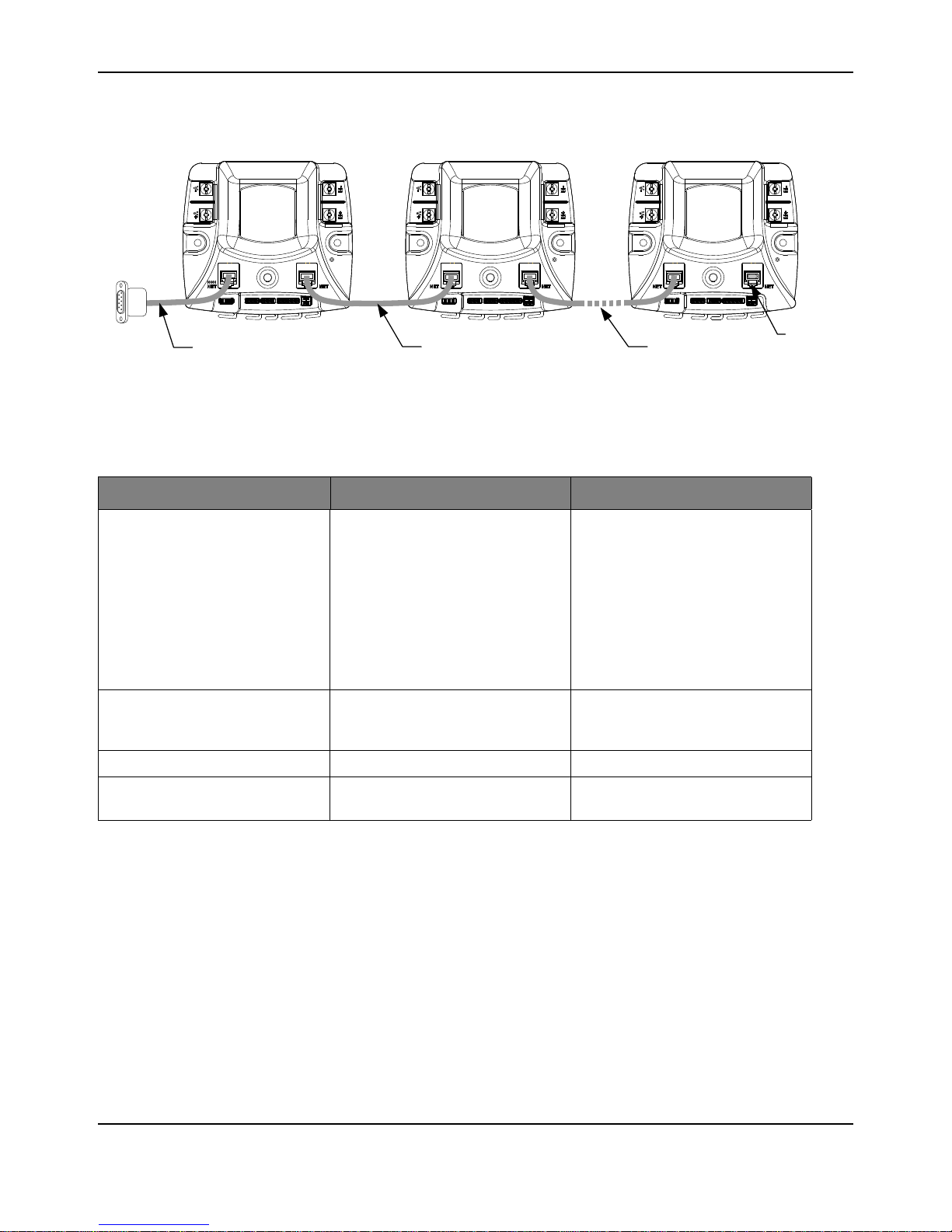
CAN Network
A CAN network consists of one or more Jaguar modules, an interface or bridge, and a host
controller. Figure 8-1 shows a typical configuration.
January 5, 2011 25
Page 26
Operation Using the CAN Interface
Connect to cRIO
Seri al Port
Jaguar or Black JaguarBlack Jaguar
Serial to 6P6C cable
Jaguar or Black Jaguar
Terminator
Plug
Additional Jaguars6P4C or 6P6C modular cable
Figure 8-1. CAN Network Topology
CAN cabling follows a daisy-chained topology using modular cable. Table 8-1 lists network
parameters.
Table 8-1. CAN Wiring Parameters
Parameter Value Notes
Maximum Nodes 16 A node is defined as a device on the
CAN network. This includes all
Jaguar modules and any device that
sends and receives CAN messages.
If you use the Black Jaguar as a
bridge, all Jaguar modules (gray or
black, including the Bridge) count as
nodes, but the computer (or CRIO)
does not since it is sending
messages over the serial port.
Total Cable Length (maximum) 20 ft / 6.1m Tip: Start with this length of bulk cable
and cut all segments from it to ensure
compliance.
Termination Resistance 100 At each end of the network.
Cable Type 4 or 6 conductor modular cable. 28 or
26 AWG.
See Appendix A, “Jaguar Communication Cables,” on page 29 for cable and terminator assembly
instructions.
Control Options for Networked Jaguar Modules
The Host controller on a Jaguar network requires a software driver to implement the CAN
communication protocol. Protocol details are available from the RDK-BDC24 pages at
www.luminarymicro.com/jaguar To simplify programming, National Instruments and Texas
Instruments have created a range of tools to simplify Jaguar control.
The following Host tools/APIs/Virtual Instruments are available:
BDC-COMM is a Windows application for configuring, testing, and performing firmware
upgrades.
26 January 5, 2011
Page 27

Getting Started Guide
LabView VI
Java API
C++ API
Example source code for a host-based on a Stellaris Microcontroller can be found in
StellarisWare® (\boards\rdk-bdc\bdc-ui) also available at www.luminarymicro.com/jaguar.
January 5, 2011 27
Page 28

Operation Using the CAN Interface
28 January 5, 2011
Page 29
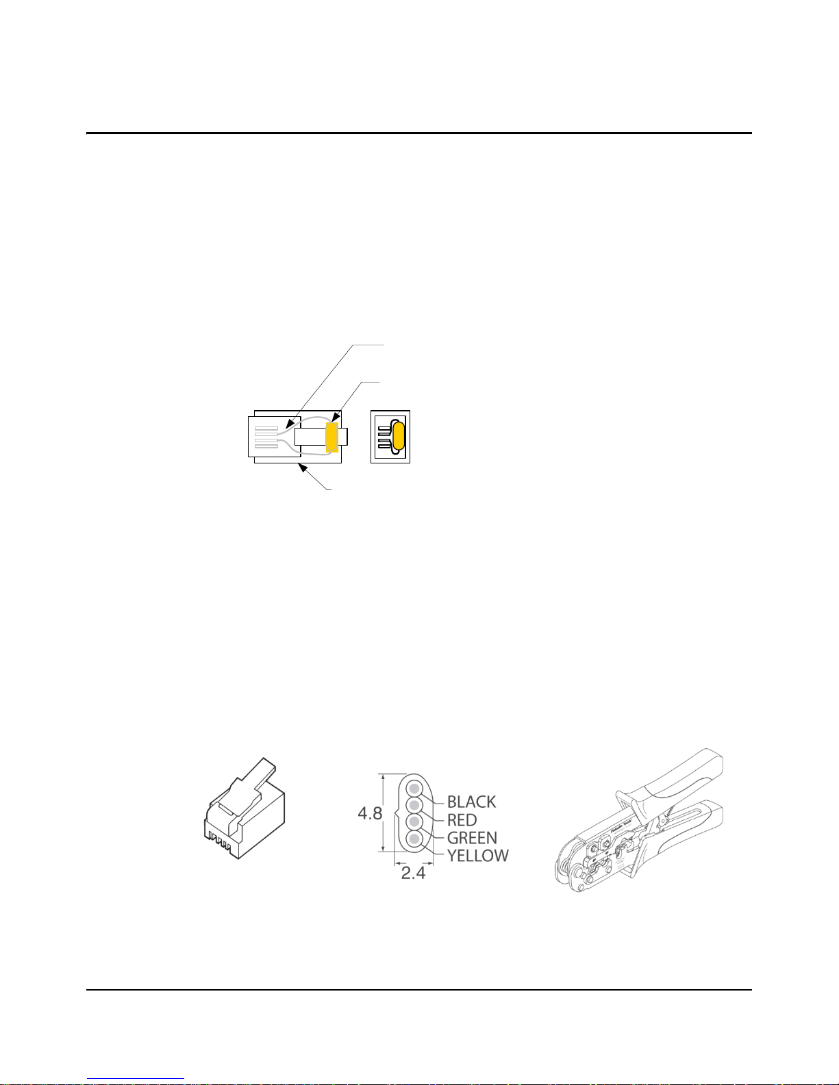
100 ohm 1/6 W Resistor
Digikey 100EBK- ND or similar
6P6C Modular Plug
AMP 5- 556384- 3 or sim ilar
Crimp resistor lead s
to center contacts
Modular plug for stranded flat oval cable
AMP P/No. 5-641335
Digikey Stock No. A9092-ND
Modular cable – 4 conductor
Assmann Elect. AT-K-26-4-S/100-R
Digikey Stock No. A0043R-100-ND
2x
6P6C/6P4C Modular Plug Crimp Tool
APPENDIX A
Jaguar Communication Cables
CAN Terminator
Because the CAN signals operate at high bit rates (1 MBPS), a terminator is required at each end
of the network. A simple network might work with a single terminator, but this is not recommended
for normal use. The termination resistor is also important for returning the CAN signaling levels to
the recessive state when no nodes are transmitting. Figure A-1 shows the recommended
terminator construction.
Figure A-1. CAN Terminator Plug
CAN Cable
Use CAN cables to daisy-chain the network between Jaguar modules. Standard off-the-shelf
modular 6P6C cables can be used. Cables must be “straight-pinned,” which means
Pin 1 > 1, Pin 2 > 2, and so on. This is also referred to as a reverse-cable because the tabs on the
connectors are on the opposite sides of the cable. The CAN cable needs only 4 conductors, but it
is acceptable to use a 6-conductor cable and plugs. A suitable 6-ft off-the-shelf 6P4C cable is
Digikey Stock No. A2662R-07-ND.
Figure A-2 shows the materials needed to build custom-length CAN cables. Apart from a modular
plug crimp tool, no special tools are required.
Figure A-2. Materials Needed to Assemble Custom-Length 6P4C Cable
January 5, 2011 29
Page 30
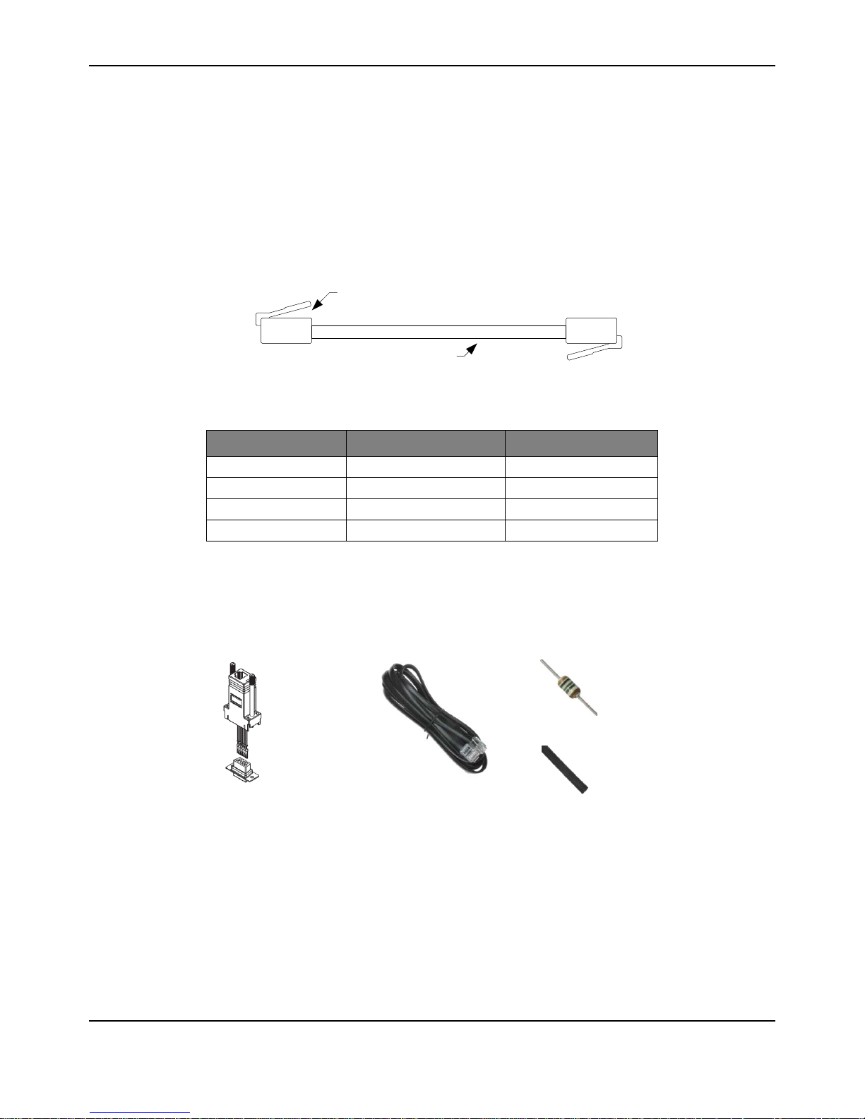
RS232 Cable
Modular Plug
4or 6 conductor cable
Modular adapter
6P6C to DB- 9 Female
CUI P/No AMK-0003
Digikey Stock No . 046-0003-ND
Modular cord
6 contact 6 conductor, reversed
Assmann Elect. AT-S-26-6/6/B-7/R-R
Digikey Stock No. 046-0003-ND
Resistor 100Ω 1%
Panasonic ERO-S2PHF1200
Digikey Stock N o. P100CACT-ND
Heatshrink tubing 1/8" diameter
Digikey Stock No . Q2F018B-ND
CAN Cable Assembly
Follow these steps to complete cable assembly (shown in Figure A-3):
1. Cut modular cable to length
2. Use the crimp to strip the outer jacket from each end of the cable.
3. Insert wires into the modular plug and load into crimper.
4. Close crimper to complete the connections and secure the cable.
Figure A-3. Completed Cable Assembly
CAN Cable Pin Assignments
Plug Wire Color Jaguar Use
1 Black -
2 Red CAN H
3 Green CAN L
4 Yellow GND
RS232 Cable
Figure A-4 shows the materials needed to build the RS232 cable. Apart from a soldering-iron, no
special tools are required.
Figure A-4. Materials Needed to Assemble RS232 Cable Components
RS232 Cable Assembly
Follow these steps to complete cable assembly (shown in Figure A-4):
1. Take the Modular Adapter and cut the black wire as short as possible. This wire is unused.
2. Cut off the terminals on the Red and Green wires. Strip then solder the Red and Green wires
to the 100 resistor. Use a section of heat shrink to protect the resistor and solder connections.
30 January 5, 2011
Page 31

3. Insert remaining terminals into the DB9 receptacle. Pin numbers are indicated on the plastic
connector body.
– White/Pin 3
– Blue/Pin 2
– Yellow/Pin 5
4. Slide the back-shell over the connector, then insert the modular cable to complete the
assembly.
RS232 Cable Pin Assignments
6P6C Wire Color Jaguar Use PC Use DB9 Pin
1WhiteRXDTXD 3
2 Black - - -
3 Red CAN H - -
4 Green CAN L - -
5 Yellow GND GND 5
6BlueTXDRXD2
Getting Started Guide
External References
The following references are also useful for working with MDL-BDC24 module:
The MDL-BDC24 Data Sheet contains detailed electrical specifications and connector details.
The BDC-COMM User’s Guide provides instructions on how to use the BDC-COMM GUI and
command line applications to control Jaguar networks.
MDL-BDC24 FAQ
January 5, 2011 31
Page 32

External References
32 January 5, 2011
Page 33

IMPORTANT NOTICE
Texas Instruments Incorporated and its subsidiaries (TI) reserve the right to make corrections, modifications, enhancements, improvements,
and other changes to its products and services at any time and to discontinue any product or service without notice. Customers should
obtain the latest relevant information before placing orders and should verify that such information is current and complete. All products are
sold subject to TI’s terms and conditions of sale supplied at the time of order acknowledgment.
TI warrants performance of its hardware products to the specifications applicable at the time of sale in accordance with TI’s standard
warranty. Testing and other quality control techniques are used to the extent TI deems necessary to support this warranty. Except where
mandated by government requirements, testing of all parameters of each product is not necessarily performed.
TI assumes no liability for applications assistance or customer product design. Customers are responsible for their products and
applications using TI components. To minimize the risks associated with customer products and applications, customers should provide
adequate design and operating safeguards.
TI does not warrant or represent that any license, either express or implied, is granted under any TI patent right, copyright, mask work right,
or other TI intellectual property right relating to any combination, machine, or process in which TI products or services are used. Information
published by TI regarding third-party products or services does not constitute a license from TI to use such products or services or a
warranty or endorsement thereof. Use of such information may require a license from a third party under the patents or other intellectual
property of the third party, or a license from TI under the patents or other intellectual property of TI.
Reproduction of TI information in TI data books or data sheets is permissible only if reproduction is without alteration and is accompanied
by all associated warranties, conditions, limitations, and notices. Reproduction of this information with alteration is an unfair and deceptive
business practice. TI is not responsible or liable for such altered documentation. Information of third parties may be subject to additional
restrictions.
Resale of TI products or services with statements different from or beyond the parameters stated by TI for that product or service voids all
express and any implied warranties for the associated TI product or service and is an unfair and deceptive business practice. TI is not
responsible or liable for any such statements.
TI products are not authorized for use in safety-critical applications (such as life support) where a failure of the TI product would reasonably
be expected to cause severe personal injury or death, unless officers of the parties have executed an agreement specifically governing
such use. Buyers represent that they have all necessary expertise in the safety and regulatory ramifications of their applications, and
acknowledge and agree that they are solely responsible for all legal, regulatory and safety-related requirements concerning their products
and any use of TI products in such safety-critical applications, notwithstanding any applications-related information or support that may be
provided by TI. Further, Buyers must fully indemnify TI and its representatives against any damages arising out of the use of TI products in
such safety-critical applications.
TI products are neither designed nor intended for use in military/aerospace applications or environments unless the TI products are
specifically designated by TI as military-grade or "enhanced plastic." Only products designated by TI as military-grade meet military
specifications. Buyers acknowledge and agree that any such use of TI products which TI has not designated as military-grade is solely at
the Buyer's risk, and that they are solely responsible for compliance with all legal and regulatory requirements in connection with such use.
TI products are neither designed nor intended for use in automotive applications or environments unless the specific TI products are
designated by TI as compliant with ISO/TS 16949 requirements. Buyers acknowledge and agree that, if they use any non-designated
products in automotive applications, TI will not be responsible for any failure to meet such requirements.
Following are URLs where you can obtain information on other Texas Instruments products and application solutions:
Products Applications
Audio www.ti.com/audio Communications and Telecom www.ti.com/communications
Amplifiers amplifier.ti.com Computers and Peripherals www.ti.com/computers
Data Converters dataconverter.ti.com Consumer Electronics www.ti.com/consumer-apps
DLP® Products www.dlp.com Energy and Lighting www.ti.com/energy
DSP dsp.ti.com Industrial www.ti.com/industrial
Clocks and Timers www.ti.com/clocks Medical www.ti.com/medical
Interface interface.ti.com Security www.ti.com/security
Logic logic.ti.com Space, Avionics and Defense www.ti.com/space-avionics-defense
Power Mgmt power.ti.com Transportation and www.ti.com/automotive
Microcontrollers microcontroller.ti.com Video and Imaging www.ti.com/video
RFID www.ti-rfid.com Wireless www.ti.com/wireless-apps
RF/IF and ZigBee® Solutions www.ti.com/lprf
TI E2E Community Home Page e2e.ti.com
Automotive
Mailing Address: Texas Instruments, Post Office Box 655303, Dallas, Texas 75265
Copyright © 2011, Texas Instruments Incorporated
 Loading...