

Page 1

Stellaris® LM3S1968 Evaluation Board
User’s Manual
EK-LM3S1968-03 Copyright © 2007–2010 Texas Instruments
Page 2
Copyright
Copyright © 2007–2010 Texas Instruments, Inc. All rights reserved. Stellaris and StellarisWare are registered trademarks of Texas Instruments.
ARM and Thumb are registered trademarks, and Cortex is a trademark of ARM Limited. Other names and brands may be claimed as the property
of others.
Texas Instruments
108 Wild Basin, Suite 350
Austin, TX 78746
http://www.ti.com/stellaris
2 January 6, 2010
Page 3

Stellaris® LM3S1968 Evaluation Board
Table of Contents
Chapter 1: Stellaris® LM3S1968 Evaluation Board ....................................................................................... 7
Features..............................................................................................................................................................8
Block Diagram ....................................................................................................................................................8
Evaluation Kit Contents ...................................................................................................................................... 9
Evaluation Board Specifications .....................................................................................................................9
Features of the LM3S1968 Microcontroller.........................................................................................................9
Chapter 2: Hardware Description.................................................................................................................. 11
LM3S1968 Evaluation Board..... ... ... .... ... ... ... .... ................................................................................................ 11
LM3S1968 Microcontroller Overview........ .... ... ... ... ... .... ... .................................................... ... ... ... ................11
Hibernation Module.......................................................................................................................................11
Clocking........................................................................................................................................................ 11
Reset.............................................................................................................................................................11
Power Supplies.............................................................................................................................................12
Debugging.....................................................................................................................................................12
USB Device Controller Functions ..................................................................................................................... 13
USB Overview........................... ... .................................................... ............................................................. 13
USB to JTAG/SWD............. ... ... ... .... ... ... .................................................... ................................................... 13
Virtual COM Port........................................................................................................................................... 13
Serial Wire Out..............................................................................................................................................14
Organic LED Display ........................................................................................................................................ 14
Virt(ual CO)-5.8(M Port)-78.1(.)-5.8(...)-5.8(...(...)-5.8(...)-5.8(....)-5.8(...)-5.8()-5.7(...)3-34...)-5.8(....)-5.8(...)-5.8(...)-Design Guidelin............................................................
January 6, 2010 3
Page 4

List of Tables
Table 2-1. Stellaris LM3S1968 Evaluation Board Hardware Debugging Configurations ... .... ... ... ...... .... ... ... ... 12
Table 2-2. Isolating On-Board Hardware........................................................................................................15
Table B-1. I/O Breakout Pads.........................................................................................................................27
Table B-2. Recommended Connectors................. ... ... .... ... .................................................... ... ... ... ... .............28
Table B-3. 20-Pin JTAG/SWD Configuration..................................................................................................28
4 January 6, 2010
Page 5

Stellaris® LM3S1968 Evaluation Board
List of Figures
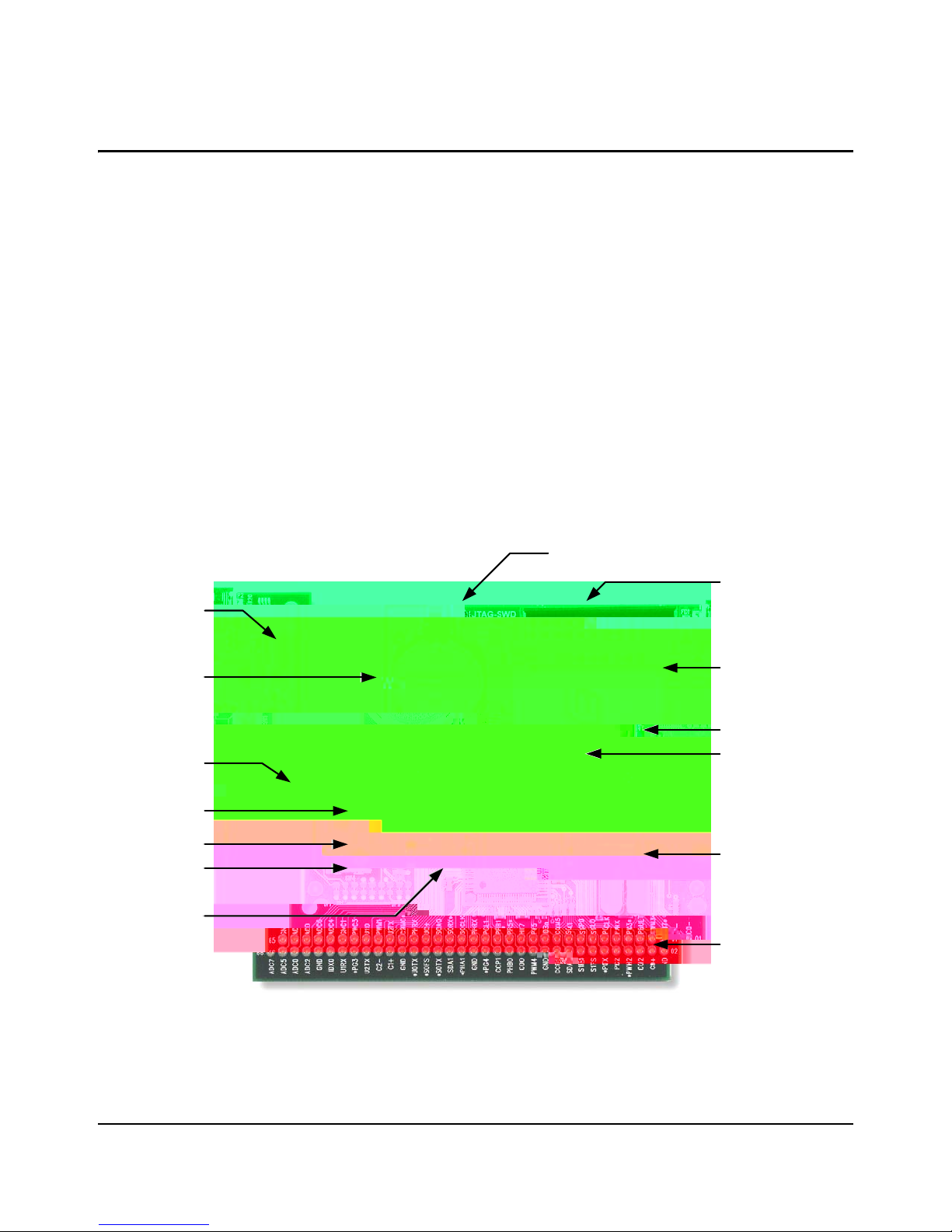
Figure 1-1. Stellaris LM3S1968 Evaluation Board Layout.................................................................................7
Figure 1-2. LM3S1968 Evaluation Board Block Diagram.................................................................................. 8
Figure 2-1. ICD Interface Mode ....................................................................................................................... 16
Figure B-1. Component Locations ...................................................................................................................25
Figure B-2. LM3S1968 Evaluation Board Dimensions..................................... ... ... .... ......................................26
January 6, 2010 5
Page 6

6 January 6, 2010
Page 7
Stellaris® LM3S1968 Evaluation Board
USB Device
Interface
Lithium coin cell
66 pin I/O break - out
header
Navigation
Switches
Select switch
St at us LEDs
Speaker
Reset switch
Power LED
OLED Graphics
Display
JTAG/SW D input and out put
Stellaris
TM
LM3S1968
Microcontroller
In-circuit D ebug
Interface
Hi bernat e LE D
The Stellaris® LM3S1968 Evaluation Board is a compact and versatile evaluation platform for the
Stellaris LM3S1968 ARM® Cortex™-M3-based microcontrolle r. The evaluation kit design
highlights the LM3S1968 microcontroller's peripherals and its Hibernation module.
A 3V lithium battery, included in the kit, supplies power to the Hibernation module and maintains
data and real-time clock information for ab out two years in the absence of USB power.
You can use the EVB either as an evaluation platform or as a low-cost in-circuit debug interface
(ICDI). In debug interface mode, the on-board microcontroller is disabled, allowing connection of
the debug signals to an external Stellaris microcontroller target. The kit is also compatible with
high-performance external JTAG debuggers.
This evaluation kit enables quick evaluation, prototype development, and creation of
application-specific designs using the LM3S1968's broad range of peripherals. The kit also
includes extensive source-code examples, allowing you to start building C code applications
quickly.
Figure 1-1. Stellaris LM3S1968 Evaluation Board Layou t
January 6, 2010 7
Page 8
Stellaris® LM3S1968 Evaluation Board
USB
Stellaris
LM3S1968
Microcontroller
Features
The Stellaris LM3S1968 Evaluation Kit includes the following features:
Stellaris LM3S1968 microcontr olle r
Simple setup; USB cable provides serial communication, debugging, and power
OLED graphics display with 128 x 96 pixel resolution
User LED, navigation switches, and select pushbuttons
8
Ω magnetic speaker with class D amplifier
Internal 3 V battery and support for on-chip hibernation module
USB interface for debugging and power supply
Standard ARM® 20-pin JTAG debug connector with input and output modes
LM3S1968 I/O available on labeled break-out pads
Block Diagram
Figure 1-2. LM3S1968 Evaluation Board Block Diagram
8 January 6, 2010
Page 9

Evaluation Kit Contents
The evaluation kit contains everything needed to develop and run applications for S tellaris
microcontrollers including:
LM3S1968 evaluation board (EVB)
USB cable
20-pin JTAG/SWD target cable
CD containing:
– A supported version of one of the following (including a toolchain-specific Quickstart
guide):
• Keil™ RealView® Microcontroller Development Kit (MDK-ARM)
• IAR Embedded Workbench
• Code Sourcery GCC development tools
• Code Red Technologies development tools
• Texas Instruments’ Code Composer Studio™ IDE
– Complete documentation
Stellaris® LM3S1968 Evaluation Board
– Quickstart application source code
– Stellaris® Firmware Development Package with example source code
Evaluation Board Specifications
Board supply voltage: 4.37–5.25 Vdc from USB connector
January 6, 2010 9
Page 10

Stellaris® LM3S1968 Evaluation Board
Eight 10-bit ADC channels (inputs) when used as single-ended inputs
Three independent integrated analog comparators
Two I
2
C modules
Three PWM generator blocks
– One 16-bit counter
– Two comparators
– Produces two independent PWM signals
– One dead-band generator
Two QEI modules with position integrator for tracking encoder position
5 to 52 GPIOs, depending on user configuration
On-chip low drop-out (LDO) voltage regulator
Hibernation module
10 January 6, 2010
Page 11

Hardware Description
In addition to a microcontroller, the Stellaris LM3S1968 evaluation board includes a range of useful
peripherals and an integrated in-circuit debug interface (ICDI). This chapter describes how these
peripherals operate and interface to the microcontroller.
LM3S1968 Evaluation Board
LM3S1968 Microcontroller Overview
The heart of the EVB is a Stellaris LM3S1968 ARM Cortex-M3-based microcontroller. The
LM3S1968 offers 256-KB Flash memory, 50-MHz operation, and a wide range of peripherals.
Refer to the LM3S1968 data sheet (order number DS-LM3S1968) for complete device details.
The LM3S1968 microcontroller is factory programmed with a quickstart demo program. The
quickstart program resides in the LM3S1968 on-chip Fl ash memory and runs each time power is
applied unless the quickstart has been replaced with a user program.
Hibernation Module
The Hibernation Module manages removal and restoration of power to the microcontroller and
peripherals while maintaining a real-time clock (RTC) and non-volatile memory. The EVB include s
a 3 V Lithium battery to maintain Hibernate module power when USB power is unavailable.
January 6, 2010 11
Page 12

Hardware Description
Internal debug mode—By the USB device controller (U5 FT2232) when instructed by
debugger
The LM3S1968 microcontroller has an internal power-on reset, so the external circuit s used in the
EVB are not required in typical applications.
Power Supplies
In normal operating mode, the LM3S1968 is powered from a +3.3-V supply. A low drop-out (LDO)
regulator converts +5-V power from the USB cable to +3.3-V. +3.3-V power is available for
powering external circuits.
If +5-V is removed, the Hibernation module will remain powered by the 3-V lithium battery. Other
microcontroller and board functions will not function until power is restored.
12 January 6, 2010
Page 13

Page 14

Hardware Description
Serial Wire Out
The evaluation board supports the Cortex-M3 serial-wire output (SWO) trace capabilities. Under
debugger control, the CPLD can route the SWO datastream to the virtual communication port
(VCP) transmit channel. The debugger can then decode and interpret the trace information
received from the VCP. The normal VCP connection to UART0 is interrupted when using SWO. Not
all debuggers support SWO. Refer to the S tellaris LM 3S3748 dat a sheet for additional infor mation
on the trace port interface unit (TPIU).
Organic LED Display
The EVB features an Organic LED (OLED) graphics display with 128 x 96 pixel resolution. OLED
is a new technology that offers many advantages over LCD display technology. The display is
protected during shipping by a thin, protective plastic film. The film can be removed using a p air of
tweezers.
Features
RiT Display P14201 series display
128 colu mn s by 96 row s
High-contrast (typ. 500:1)
Excellent brightness (120 cd/m
2
)
Fast 10 us response
Control Interface
The OLED display has a built-in controller IC with synchronous serial and parallel interfaces.
Synchronous serial (SSI) is used on the EVB as it requires fewer microcontroller pins. Data cannot
be read from the OLED controller; only one data line is necessary. The Stellaris® Firmware
Development Package (included on the Documentation and Software CD) contains complete
drivers with source-code for the OLED display.
Power Supply
A +15-V supply is needed to bias the OLED display. A FAN5331 device from Fairchild combines
with a few external components to complete a boost converter. A GPIO (PH3/FAULT) is assigned
to turn on and off the controller as nece ssary for power rail sequen cing. When the OLED display is
operating, a small amount of power can be drawn from the +15-V supply to power other devices.
Design Guidelines
The OLED display has a lifetime of about 13,000 hours. It is also prone to degradation due to
burn-in, similar to CRT and plasma displays. The quickstart application includes both a screen
saver and a power-down mode to extend display life. These factors should be considered when
developing EVB applications that use the OLED display.
Further Reference
For additional information on the RiT OLED display, visit www.ritekdisplay.com.
14 January 6, 2010
Page 15

Other Peripherals
Speaker
The LM3S1968 evaluation board's speaker circuit can be used in either tone or waveform mode.
The quick-start application uses tone mode.
In tone mode, the LM3S1968 microcontroller's PWM module directly generates tones within the
audible frequency range. The width of the pulses determines the volume. If only one PWM signal
(PWM2 or PWM3) is used, the non-PWM signal should be configured as a general-purpose
output. For increased speaker volume, PWM 2 and PWM 3 ca n be con fig ured as c omp lem e ntary
drive signals. In tone mode, be careful to avoid large DC currents in the speaker.
Waveform mode uses two high-frequency PWM signals to drive a MOSFET H-bridge with an
output filter. This circuit is essentially a Class-D amplifier. The symmetrical 2nd order low-pass L-C
filter has a cut-off frequency of approximately 33 kHz. The microcontroller's PWM module should
be configured with a PWM frequency of at least 100 kHz. Using 500 kHz improves audio quality
Stellaris® LM3S1968 Evaluation Board
January 6, 2010 15
Page 16

Hardware Description
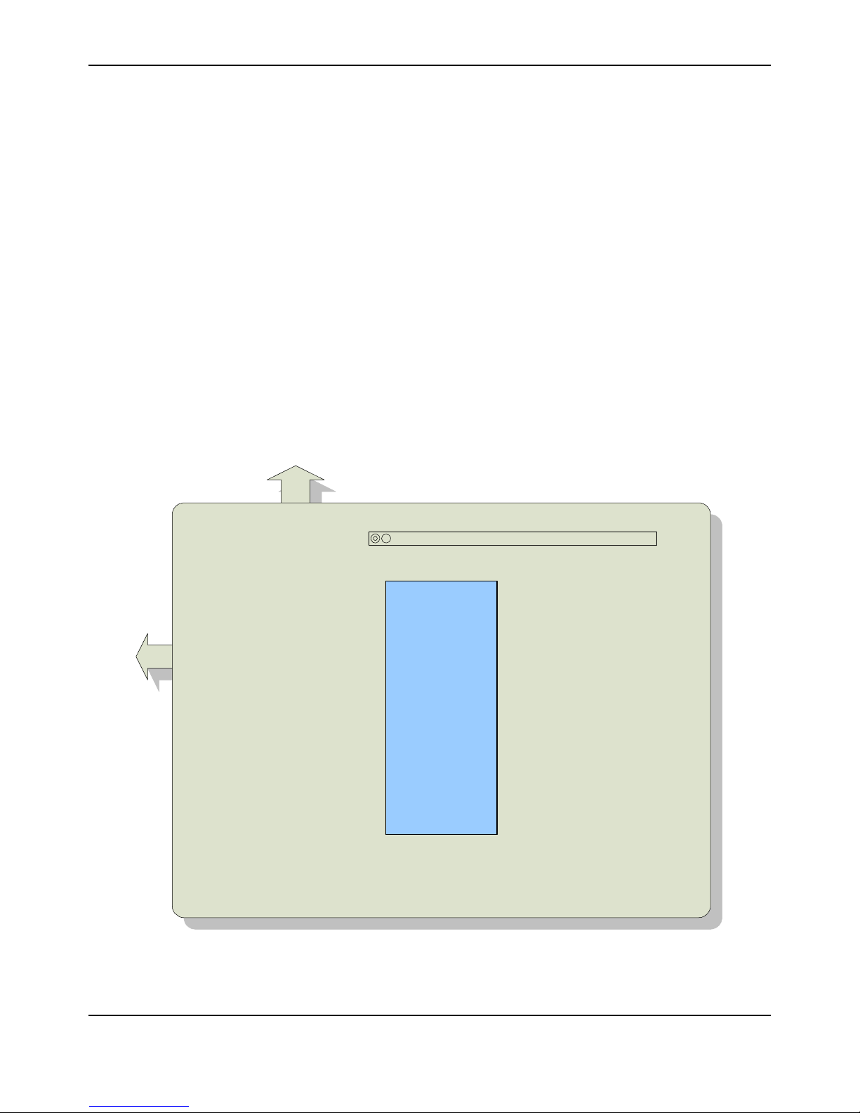
Evaluation Board
Target
Board
Stellaris
MCU
Target
Cable
`
Table 2-2. Isolating On-Board Hardware (Continued)
Microcontroller Pin Microcontroller Assignment To Isolate, Remove...
Pin 29 PA3/SSI0FSS OLED display chip select JP5
Pin 37 PG6/PHA1 Right switch JP6
Pin 36 PG7/PHB1 Select switch JP7
Pin 40 PG5 Left switch JP8
Pin 41 PG4 Down switch JP9
Pin 31 PA5/SSI0TX OLED display data in JP10
Pin 28 PA2/SSI0CLK OLED display clock JP1 1
Pin 34 PA6/I2C1SCL OLED display data/control select JP12
Pin 27 PA1/U0TX Virtual COM port transmit JP13
Pin 86 PH0/PWM2 Sound+ JP14
Pin 85 PH1/PWM3 Sound- JP15
Interfacing to the EVB
An array of accessible I/O signals makes it easy to interface the EVB to external circuits. All
LM3S1968 I/O lines (except those with both JTAG and SWD functions) are brought out to 0.1”
pitch pads. For quick reference, silk-screened labels on the PCB show primary pin functions.
Table B-2 on page 28 has a complete list of I/O signals as well as recommended connectors.
Most LM3S1968 I/O signals are +5-V tolerant. Refer to the LM3S1968 data sheet for detailed
electrical specifications.
Using the In-Circuit Debugger Interface
The Stellaris LM3S1968 Evaluation Kit can operate as an In-Circuit Debugger Interface (ICDI).
ICDI acts as a USB to the JTAG/SWD adaptor, allowing debugging of any external target board
that uses a Stellaris microcontroller. See “Debugging Modes” on page 12 for a description of how
to enter Debug Out mode.
Figure 2-1. ICD Interface Mode
16 January 6, 2010
Page 17

Stellaris® LM3S1968 Evaluation Board
The debug interface operates in either serial-wire debug (SWD) or full JTAG mode, depending on
the configuration in the debugger IDE.
The IDE/debugger does not distinguish between the on-EVB Stellaris microcontroller and an
external Stellaris microcontroller. The only requirement is that the correct Stellaris device is
selected in the project configuration.
January 6, 2010 17
Page 18

Hardware Description
18 January 6, 2010
Page 19

APPENDIX A
Schematics
This section contains the schematics for the LM3S1968 Evaluation Board:
LM3S1968 Microcontroller on page 20
OLED Display, Switches and Audio on page 21
USB and Debugger Interfaces on page 22
USB, Debugger Interfaces and Power on page 23
JTAG Logic with Auto Mode Detect and Hibernate on page 24
January 6, 2010 19
Page 20

1
1
2
2
3
3
4
4
5
5
6
6
D D
C C
B B
A A
Document Number:
RevSheetDate:
of
3/4/2008 1 4
Drawing Title:
Page Title:
Size
Stellaris LM3S1968 Evaluation Board
LM3S1968 Microcontroller
B
B
EK-LM3S1968
Revision Date Description
0 8/9/07 Final prototype release
History
INT_TCK
TMS/SWDIO
PC2/TDI
PC3/TDO/SWO
ADC3
ADC2
ADC1
ADC0
Page 21

1
1
2
2
3
3
4
4
5
5
6
6
D D
C C
B B
A A
Document Number:
RevSheetDate:
of
3/4/2008 2 4
Drawing Title:
Page Title:
Size
Stellaris LM3S1968 Evaluation Board
OLED Display, Switches and Audio
B
B
EK-LM3S1968
R7
330
R5
200K
OLEDDIN
OLEDCLK
+3.3V
DBGOUTLED
Reset
SW1
SW-B3S1000
WAKEn
UP_SWn
DOWN_SWn
LEFT_SWn
RIGHT_SWn
RESET_SWn
R4
10K
+3.3V
Select/Power
Up
Down
Left
Right
Debug Out
R6
330
LED
Status
R10
330
Power
128x96 OLED Graphics Display
Status LEDs
User Switches
+3.3V
C17
4.7UF
SW2
SW-B3S1000
SW3
SW-B3S1000
SW4
SW-B3S1000
SW5
SW-B3S1000
SW6
SW-B3S1000
MCURSTn
OLEDDC
LED1
Green
LED2
Red
LED3
Green
C18
OMIT
+15V
OLEDCSn
C19
0.1UF
NC
1
VCIR
2
VCOMH
3
LVSS
4
VSS
5
BS1
6
BS2
7
IREF
8
CSn
9
RESn
10
D/Cn
11
R/Wn
12
E
13
D0/SCLK
14
D1/SDIN
15
D2
16
D3
17
D4
18
D5
19
D6
20
D7
21
VDDIO
22
VDD
23
VCC
24
NC
25
U2
OLED-RIT-128X96
1
2
6
Q3A
FDG6322C
3
5
4
Q2B
FDG6322C
+3.3V
SOUND+
R8
200K
SOUND-
R9
200K
0.2W Audio Amplifier
C21
0.1UF
C22
0.1UF
4.7uH
L1
4.7uH
L2
1
2
SPK1
HIBERNATEn
Hibernate
LED4
Red
DBG+3.3V
R30
330
1
2
6
Q2A
FDG6322C
3
Page 22

1
1
2
2
3
3
4
4
5
5
6
6
D D
C C
B B
A A
Document Number:
RevSheetDate:
of
3/4/2008 3 4
Drawing Title:
Page Title:
Size
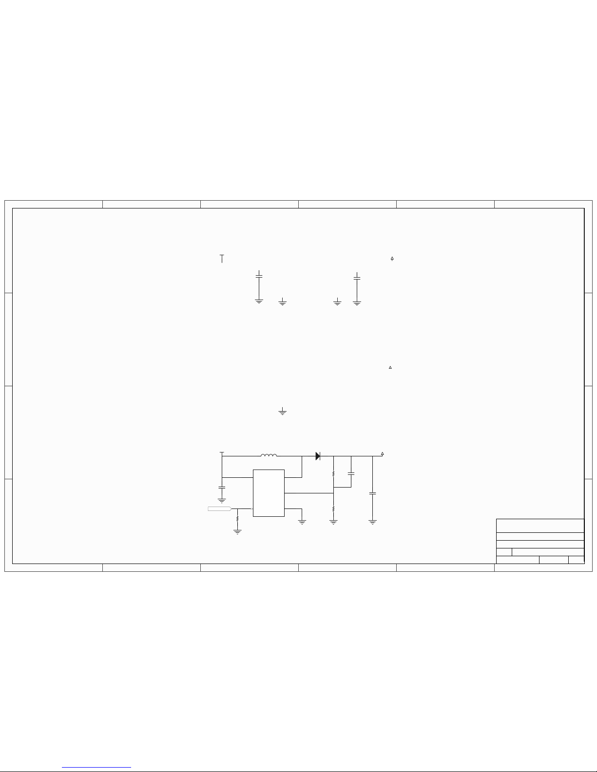
Page 23
1
1
2
2
3
3
4
4
5
5
6
6
D D
C C
B B
A A
Document Number:
RevSheetDate:
of
3/4/2008 4 4
Drawing Title:
Page Title:
Size
Stellaris LM3S1968 Evaluation Board
USB, Debugger Interfaces and Power
B
B
EK-LM3S1968
DBG+3.3V
Debugger +3.3V 200mA Power Supply
+5V
C23
4.7UF
C24
4.7UF
+15V 50mA Power Supply for OLED Display
+15V
FB
3
VIN
5
SHDNn4GND
2
SW
1
U5
FAN5331
+5V
C30
4.7UF
C31
4.7UF
D1
MBR0520
120pF
C29
R13
200K
R14
17.8K
EN+15V
R15
10K
10uH
L3
NR4018T100M
Page 24

A B C D E F G H
A B C D E F G H
1
2
3
4
5
6
7
8
1
2
3
4
5
6
7
8
I102
I100
C
DQ
I96
I105
I104
I36
I35
I18
A
B
S
I89
A
B
S
I85
A
B
S
I17
A
B
S
I106
33
I86
44
I2
21
I107
38
I70
7
Page 25

APPENDIX B
Connection Details
This appendix contains the following sections:
Component Locations
Evaluation Board Dimensions
I/O Breakout Pads
ARM Target Pinout
References
Component Locations
Figure B-1. Component Locations
January 6, 2010 25
Page 26

Evaluation Board Dimensions
Evaluation Board Dimensions
Figure B-2. LM3S1968 Evaluation Board Dimensions
26 January 6, 2010
Page 27

I/O Breakout Pads
The LM3S1968 EVB has 58 I/O pads, 13 power pads, and 1 control connection, for a total of 71
pads. Connection can be made by soldering wires directly to these pads, or by using 0.1” pitch
headers and sockets.
Note: In Table B-1, an asterisk (*) by a signal name (also on the EVB PCB) indicates the signal is
normally used for on-board functions. Normally, you should cut the associated jumper (JP1-15)
before using an assigned signal for external interfacing.
Table B-1. I/O Breakout Pads
Stellaris® LM3S1968 Evaluation Board
Description
Pad
No.
Description
Pad
No.
Description
Pad
No.
Description
Pad
No.
PB4/C0- 1 PB1/CCP2 18 PA6/I2C1SCL 35 PG3* 52
GND 2 PB0/CCP0 19 PA7/I2C1SDA 36 PD1/PWM1 53
PB5/C1- 3 GND 20 PA4/SSI0RX 37 PD2/U1RX 54
PB6/C0+ 4 PF1/IDX1 21 PA5/SSI0TX* 38 GND 55
PB7/TRST 5 PF2/PWM4 22 PA2/SSI0CLK* 39 PD0/IDX0 56
PH0/PWM2* 6 PF3/PWM5 23 PA3/SSI0FSS* 40 ADC3 57
PH1/PWM3* 7 PF4/C0O 24 PA0/U0RX* 41 GND 58
PH2* 8 HIBn 25 PA1/U0TX* 42 ADC1 59
PH3/FAULT* 9 PF0/PHB0 26 PC4/PhA0 43 ADC2 60
PC2/TDI 10 PF5 27 GND 44 ADC4 61
PC3/TDO/SWO 11 PF6/CCP1 28 PC6/C2+ 45 ADC0 62
PE3/SSI1TX 12 PF7 29 PC5/C1+ 46 ADC6 63
PE2/SSI1RX 13 PG4* 30 PG0/U2RX 47 ADC5 64
PE1/SSI1FSS 14 PG5* 31 PC7/C2- 48 GND 65
PE0/SSI1CLK 15 GND 32 PG2/PWM0* 49 ADC7 66
PB3/I2C0SDA 16 PG7/PHB1* 33 PG1/U2TX 50
PB2/I2C0SCL 17 PG6/PHA1* 34 PD3/U1TX 51
January 6, 2010 27
Page 28

Page 29

References
In addition to this document, the following references are included on the Stellaris LM3S1968
Evaluation Kit CD-ROM and are also available for download at www.ti.com/stellaris:
Stellaris LM3S1968 Evaluation Kit Quickst art Guide for appropriate tool kit (s ee “Evaluation Kit
Contents,” on page 9)
Stellaris LM3S1968 Read Me First for the CAN Evaluation Kit
StellarisWare® Driver Library, Order number SW-DRL
StellarisWare® Driver Library User’s Manual, publication number SW-DRL-UG
Stellaris LM3S1968 Data Sheet, publication DS-LM3S1968
Additional references include:
Solomon Systech SSD0323-OLED Controller Datasheet
Future Technology Devices Incorporated FT2232C Datasheet
Information on development tool being used:
– RealView MDK web site, www.keil.com/arm/rvmdkkit.asp
– IAR Embedded Workbench web site, www.iar.com
Stellaris® LM3S1968 Evaluation Board
– Code Sourcery GCC development tools web site,
www.codesourcery.com/gnu_toolchains/arm
– Code Red Technologies developm en t to ols we b site, www.code-red-tech.com
– Texas Instruments’ Code Composer Studio™ IDE web site, www.ti.com/ccs
January 6, 2010 29
Page 30

References
30 January 6, 2010
Page 31

IMPORTANT NOTICE
Texas Instruments Incorporated and its subsidiaries (TI) reserve the right to make corrections, modifications, enhancements, improvements,
and other changes to its products and services at any time and to discontinue any product or service without notice. Customers should
obtain the latest relevant information before placing orders and should verify that such information is current and complete. All products are
sold subject to TI’s terms and conditions of sale supplied at the time of order acknowledgment.
TI warrants performance of its hardware products to the specifications applicable at the time of sale in accordance with TI’s standard
warranty. Testing and other quality control techniques are used to the extent TI deems necessary to support this warranty. Except where
mandated by government requirements, testing of all parameters of each product is not necessarily performed.
TI assumes no liability for applications assistance or customer product design. Customers are responsible for their products and
applications using TI components. To minimize the risks associated with customer products and applications, customers should provide
adequate design and operating safeguards.
TI does not warrant or represent that any license, either express or implied, is granted under any TI patent right, copyright, mask work right,
or other TI intellectual property right relating to any combination, machine, or process in which TI products or services are used. Information
published by TI regarding third-party products or services does not constitute a license from TI to use such products or services or a
 Loading...