

Page 1

Application Report
SPRAA56 – September 2004
DSP/BIOS Real-Time Analysis (RTA) and Debugging
Applied to a Video Application
Brian Jeff DSP Field Software Applications
Arnie Reynoso Software Development Systems
ABSTRACT
DSP/BIOS and the Reference Frameworks allow developers to non-intrusively instrument
real-time applications. The software provided with this application note applies real-time
analysis (RTA) services to a working application—a H.263 encode/decode loopback
example for the TMS320DM642 evaluation module. The software demonstrates
techniques for benchmarking and controlling video software. It also introduces a service to
programmatically measure CPU and TSK loading. Debugging and troubleshooting
techniques for real-time applications, using Code Composer Studio, is also discussed.
Contents
1
Important Benchmarks for Video Applications.......................................................................... 2
2 Base Application Overview ......................................................................................................... 3
2.1 DSP/BIOS and RF5 Components Used.................................................................................. 5
2.2 Requirements for Viewing RTA Benchmarks.......................................................................... 7
3 Modifications to the Base Example............................................................................................. 7
3.1 Splitting the Encode and Decode CELLs................................................................................ 8
3.2 Adding the Control TSK and MBX Communication................................................................. 8
3.3 Querying the H.263 Encoder for Status .................................................................................. 9
3.4 Controlling the Frame Rate................................................................................................... 10
4 RTA Techniques for Performance Measurement..................................................................... 11
4.1 Measuring Function Execution Time with the UTL Module ................................................... 11
4.2 Measuring Task Scheduling Latencies ................................................................................. 12
4.3 Measuring End-to-End Latencies.......................................................................................... 12
4.4 Measuring the Frame Rate ................................................................................................... 13
4.5 Simulating High CPU Load Stress Conditions with Dummy NOP Loads............................... 14
4.6 Programmatic Measurement of Total CPU Load................................................................... 14
4.7 Memory Bus Utilization......................................................................................................... 15
4.8 Bitrate and Frame Type........................................................................................................ 17
4.9 Methods for Transmitting Measured Performance Data........................................................ 18
4.10 Application-Specific Control via GEL Scripts in CCStudio..................................................... 19
5 Viewing Benchmarks in the Instrumented Application ........................................................... 19
5.1 Requirements ....................................................................................................................... 19
5.2 Running the Application........................................................................................................ 20
5.3 Interpreting the Benchmarks................................................................................................. 22
5.4 Controlling the Run-Time Parameters Dynamically............................................................... 25
6 References.................................................................................................................................. 26
Appendix A. Performance Impact..................................................................................................... 27
A.1 Overhead of Performance Measurement Techniques........................................................... 27
A.2 RTA Effects on CPU Load .................................................................................................... 27
A.3 Memory Footprint ................................................................................................................. 28
1
Page 2

SPRAA56
Figures
Figure 1.
Figure 2. Detailed Application Data Flow Showing Memory Buffers........................................... 8
Figure 3. Task Partitioning in the Modified Application ............................................................... 9
Figure 4. CPU Load Measurement at Run-Time .......................................................................... 15
Figure 5. External ↔ Internal Memory Transfers, YUV4:2:0 to 4:2:2 Conversion Function .... 16
Figure 6. Workspace Including RTA Windows............................................................................ 22
Figure 7. Statistics View Showing Benchmark Measurements.................................................. 23
Basic Data Flow of the Video Application...................................................................... 4
1 Important Benchmarks for Video Applications
Diverse video applications often require similar benchmarks to quantify their performance. Some
of the most commonly needed benchmarks are as follows:
• Frame rate
• Resolution
• End-to-end latency
• Processor utilization
• Bitrate*
• Quantization factor*
• Frame type*
• Group-of-pictures (GOP) structure*
Items marked with an asterisk are of importance in applications where encoders or decoders are
involved. This application note provides a method for measuring many of these benchmarks
during the capture, processing, and display phases of the example video application.
Frame rate is the rate at which frames are captured, processed, and displayed. The capture,
process, and display frame rates can differ by design or under overloaded conditions where
frames are “dropped.” Therefore, it is important to measure all three frame rates separately.
Resolution is the size in pixels of the capture, processing, and display. Resolution is typically
static at run-time, so it is not usually benchmarked with real-time tools. However, it is important
to know the capture, processing, and display resolutions of the system design. For example, the
H.263 loopback application used in this application note captures and displays video in D1
resolution and processes in 4CIF resolution.
End-to-end latency is a measurement of the time between the capture of a video frame in realtime and the display of that same video frame some number of milliseconds later.
Processor utilization is the percentage of DSP resources used by an algorithm. In video
applications, the significant benchmarks of processor utilization include not only the number of
CPU cycles used, but also the memory bus utilization since such large amounts of data must be
moved from external memory to L2 and back repeatedly.
Bitrate is the number of bits per second output by a video encoder, or delivered to a video
decoder. Higher bitrates are generally associated with higher quality video. The bitrate often
varies with the complexity and motion in a video source, so it is important to measure bitrate
dynamically in video applications.
2 DSP/BIOS Real-Time Analysis (RTA) and Debugging Applied to a Video Application
Page 3

Quantization is the process of dividing a continuous range of input values into a finite number of
subranges. Each subrange is assigned a specific output value. The Q factor, or quantization
factor, describes the level of quantization used to store the frequency domain representation of
the encoded image. Q factor often varies dynamically in an encoder when a constant bitrate is
targeted, so it is useful to display the Q factor dynamically with the video stream.
Frame type designates whether a particular frame was encoded independently (I frame) or
whether it depends upon previous frames (P) or both previous and future frames (B). Frame
type is a useful benchmark when shown in real-time. Note that P and B frame types are relevant
for H.263, MPEG-4, MPEG-2, and similar compression standards. They are not relevant for
JPEG or uncompressed video applications.
Group-of-pictures (GOP) structure is the sequence of frame types (I, P, and B) produced by the
encoder. Common structure lengths are 12 and 15 frames. For example, IBBPBBPBBPBBPBB.
If the video stream does not change greatly from frame to frame, P frames may be about 10%
the size of I frames, and B frames may be about 2% the size of I frames.
2 Base Application Overview
The base "h263_loopback" example used to create the application described here is a video
application supplied with the TMS320DM642 evaluation module board support package. After
you install the board support package, the source code and included object libraries for the base
example are in the <CCS_install_dir>\boards\evmdm642\examples\video\h263_loopback
directory.
SPRAA56
The H.263 loopback example was chosen because it integrates the following pieces of
eXpressDSP software in a working video system:
• xDAIS-compliant algorithms
• eXpressDSP-compliant video device drivers from the device driver kit (DDK)
• DSP/BIOS real-time kernel for scheduling
• Chip Support Library (CSL) for low level device function calls
• Reference Framework Level 5 (RF5) as a software / scheduling foundation
This example could be used as the basis for any video design that uses an xDAIS-compliant
codec. It could be modified to support networking or streaming input/output by following the
video networking examples provided with the EVM’s board support package.
While some real-time analysis tools are enabled in the base example, this note describes a
more comprehensive set of tools for real-time analysis, benchmarking, and debugging. This set
of tools can be used with any video application that has a similar DSP/BIOS-based foundation.
The design of the base example is described in detail in the H.263 Loopback on the
DM642 EVM (SPRA933), but a brief description of the design and components used is
provided here for reference.
DSP/BIOS Real-Time Analysis (RTA) and Debugging Applied to a Video Application 3
Page 4
SPRAA56
KTSK
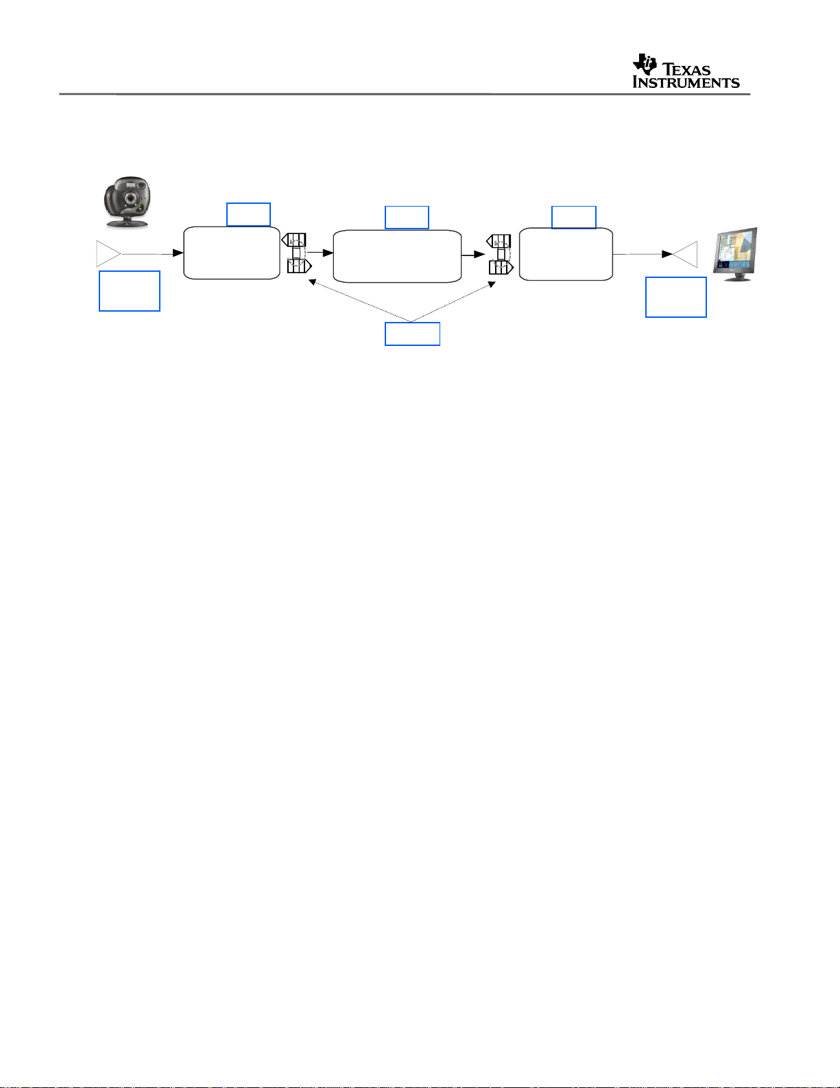
Figure 1 shows a simplified view of the sequential flow of capture, processing, and display tasks
in the application.
Camera
TS
tskInput
Device
Driver
tskVideoProcess
TSK
tskOutput
SCOM
Device
Driver
Figure 1. Basic Data Flow of the Video Application
Before video data reaches the first stage, it must be converted to digital data, a process that is
managed by the input device driver. Analog video input is converted by an on-board NTSC
decoder chip into a digital bitstream compliant with the BT.656 format with embedded
synchronization. The decoder chip sends the bitstream to the TMS320DM642 DSP’s video port.
A device driver, implementing the IOM interface recommended in the DSP/BIOS Driver
Developer’s Guide (SPRU616), is used to manage the initialization and synchronization of the
EDMA channel, the video port, and the NTSC decoder used for video capture.
In Figure 1, TSK refers to a DSP/BIOS task, which is described in detail in the DSP/BIOS User's
Guide and the DSP/BIOS API Reference. Tasks support blocking calls, which are used to
synchronize the application and the video data stream. The main data flow then has three
stages: capture, processing, and display. Each stage has its own task object.
• The example’s first stage is a task called tskInput, which runs the tskVideoInput function.
The task receives digital video buffers from the device driver. It then converts the buffers to
the 4:2:0 format from the 4:2:2 formatted data it receives from the driver.
• The next stage, the tskVideoProcess task, which runs the tskProcess function. The task
includes algorithms that require input data in the 4:2:0 format. The tskInput task sends a
message to the tskVideoProcess task with pointers to the newly formatted data buffers. The
tskVideoProcess task then calls an xDAIS-compliant H.263 encoder algorithm to compress
the data, which is stored in an intermediate buffer. A second xDAIS-compliant algorithm, an
H.263 decoder, is called to decode the data in the buffer.
• The tskOutput task runs the tskVideoOutput function. It converts the data back to 4:2:2
format as required by the output driver and the NTSC encoder chip, and calls the driver with
the data buffer for display. The output driver is also an eXpressDSP compliant device driver
with the same API interface as the input driver.
Data is passed between the tasks using SCOM messaging objects to pass the pointers and
synchronization semaphore required to ready the output task. The SCOM module is from
Reference Framework 5, which is described in the next section.
4 DSP/BIOS Real-Time Analysis (RTA) and Debugging Applied to a Video Application
Page 5

2.1 DSP/BIOS and RF5 Components Used
The base application leverages various DSP/BIOS real-time analysis components to support
debugging capabilities that are not intrusive to the system performance. The following three
modules are included with the core DSP/BIOS library, and can be used in any application that
uses DSP/BIOS and on any TI DSP supported by DSP/BIOS:
• LOG – Logging events
• STS – Statistics accumulators
• TRC – Control of real-time capture
In addition to these DSP/BIOS components, the application also uses the UTL module for
debugging and diagnostics. This module is provided in the Reference Frameworks
distribution. The UTL module is described in more detail in Reference Frameworks for
eXpressDSP Software: API Refer ence (SPRA147).
In addition to modules used for real-time analysis and debugging, the base application uses the
following DSP/BIOS and Reference Frameworks (RF) modules.
• MBX – Mailbox software module for inter-task communication (DSP/BIOS)
• TSK – Task scheduling module (DSP/BIOS)
• SCOM – Synchronization and pointer-passing mechanism for data flow between TSKs (RF)
• CHAN – Instantiates and serially executes xDAIS-compliant algorithms (RF)
• CELL – Container for xDAIS algorithms in a CHAN (RF)
• ALGRF – Encapsulates the procedure for xDAIS algorithm instantiation (RF)
SPRAA56
The following module provides an interface to the video port device driver, and is described in
The TMS320DM642 Video Port Mini-Driver (SPRA918).
• FVID – Frame Video APIs for communicating with video port device drivers
A brief description of the DSP/BIOS and RF5 modules used extensively in benchmarking the
application is given in the following subsections.
2.1.1 LOG
The LOG module captures events in real time while the target program executes. You can use
the system log (LOG_system) or create user-defined logs, such as myTrace. Log buffers are of
a fixed size and reside in data memory. Individual messages use four words of storage in the
log's buffer. The first word holds a sequence number that allows the Event Log to display logs in
the correct order. The remaining three words contain data specified by the call that writes the
message to the log. The LOG module is much less intrusive to a running system (both in MIPS
and memory) than the RTS printf function, while providing a similar capability.
DSP/BIOS Real-Time Analysis (RTA) and Debugging Applied to a Video Application 5
Page 6

SPRAA56
2.1.2 STS
An STS object accumulates the following statistical information about an arbitrary 32-bit wide
data series: count, total, and maximum.
Statistics are accumulated in 32-bit variables on the target DSP and in 64-bit variables on the
host PC. When the host polls the target for real-time statistics, it resets the variables on the
target. This minimizes space requirements on the target, while allowing you to keep statistics for
long test runs.
As part of using the DSP/BIOS instrumented kernel, the application automatically acquires STS
information for HWI, PIP, PRD, SWI, and TSK objects. To use this built-in feature on TSKs, the
application must call the TSK_settime and TSK_deltatime APIs to obtain STS information.
Custom STS objects can also be created in the DSP/BIOS configuration. By using the STS APIs
for the created objects, you can determine what statistical information needs to be acquired by
the system application during run-time.
2.1.3 TRC
The TRC module manages a set of trace control bits that control the real-time capture of
program information through event logs and statistics accumulators. For greater efficiency, the
target does not execute log or statistics APIs unless tracing is enabled.
This module contains two user-defined TRC flags that can be toggled using the DSP/BIOS RTA
Control Panel in Code Composer Studio. The application can use these bits to enable or disable
sets of explicit instrumentation. The program can use the TRC_query API to check the settings
of these bits and either perform or omit instrumentation calls based on the result. DSP/BIOS
does not use or set these bits.
2.1.4 UTL
UTL is part of the Reference Frameworks distribution. The UTL module is used for debugging
and diagnostics.
The module is essentially a set of macros that can either be expanded to code that performs the
desired debugging function, or removed completely when building depending on the value of the
UTL_DBGLEVEL preprocessor flag. The UTL module encapsulates DSP/BIOS services such as
CLK, STS, and LOG in APIs. These services can be easily removed in the final build by using
the preprocessor flag, -d “UTL_DBGLEVEL=0”.
With conditional expansion of macros to code you can reduce code size and remove
unnecessary functionality in the deployment phase without having to remove development
debugging/diagnostics aids. This technique also means you don’t need to modify code at
deployment time, thus reducing the possibility of error.
6 DSP/BIOS Real-Time Analysis (RTA) and Debugging Applied to a Video Application
Page 7

2.2 Requirements for Viewing RTA Benchmarks
In order for any of the DSP/BIOS-based RTA tools to be visible, the DSP/BIOS components in
Code Composer Studio version 2.30 or earlier and version 3.0 require that the application’s .cdb
configuration file be accessible and consistent with the executable .out file.
This requirement is easily met during development. It can also be satisfied in demonstrations or
delivered test examples. If you do not want to deliver source code with the application for
external testing or demonstration, you can still enable all the RTA tools by providing a current
DSP/BIOS configuration .cdb file along with the executable .out file to be tested. The tester will
be able to view the CPU load, individual thread statistics, and other important benchmark details
described in the sections to follow.
The RTA tools can be used in stop mode or real-time mode. In the GBL module of the
DSP/BIOS configuration, you can enable or disable real-time analysis. If you disable real-time
analysis, the three RTA functions in the IDL background loop are removed. Those functions
normally move RTA data from buffers on the DSP to the host PC and calculate the CPU load for
the load graph.
When RTA is disabled, the Message Log, Statistics View, Execution Graph, and other RTA
windows are updated only when the DSP is halted. An update displays the most recent contents
of their respective buffers. This “stop mode” of RTA offers a good compromise when some
visibility is required, but the additional code and background function calls are undesirable. Stop
mode can also occur if RTA is enabled but the CPU is so heavily loaded that it never runs the
IDL background loop long enough to provide real-time updates. In either case of stop-mode
operation, the CPU Load Graph is not updated. However, the programmatic method for CPU
load measurement discussed later in this application note provides a useful working alternative.
SPRAA56
The next section describes structural modifications made to the application to make it more
suitable for benchmarking and further development.
3 Modifications to the Base Example
The application associated with this document has very few structural changes from the base
application shipped with the TMS320DM642 evaluation module. Some variables have been
renamed for readability, the encoder and decoder have been separated, and an additional task
has been added for application control. The data flow in the application has not been modified.
The steps to convert the base example to the modified example are provided in a readme file in
the directory that contains the source code.
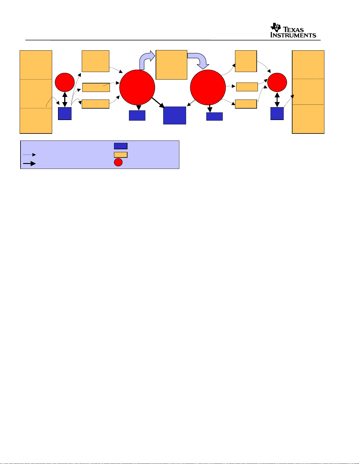
Figure 2 shows a more detailed look at the data flow in the modified H.263 loopback example:
DSP/BIOS Real-Time Analysis (RTA) and Debugging Applied to a Video Application 7
Page 8
SPRAA56
Device
Driver
Buffer
3 frames
Key
Key
DMA Read/Write (background)
DMA Read/Write (background)
Yuv
422to
420
scratch1
14 KB = 20 lines
Figure 2. Detailed Application Data Flow Showing Memory Buffers
Note: The dotted lines in Figure 2 indicate EDMA moves, and the solid lines indicate CPU
reads/writes. The application performs only CPU reads/writes from mapped internal memory,
relying on the EDMA to copy working data into internal scratch buffers.
YAfter420
414 KB
CbAfter420
CrAfter420
207 KB
720x576
H.263
enc
6 KB
Instance
memory
Internal Memory
Internal Memory
External Memory
External Memory
DSP CPU FunctionCPU Read/Write
DSP CPU FunctionCPU Read/Write
bitBuf
512 KB
Shared
Scratch
92 KB
H.263
dec
1.5 KB
Instance
memory
y
414 KB
Cr
CbA rrau
Cb
207 KB
Yuv
422to
420
scratch2
14 KB
Device
Device
Driver
Driver
Buffer
Buffer
3 frames
3 frames
3.1 Splitting the Encode and Decode CELLs
In the base example, the H.263 encoder and decoder are wrapped in sequential CELLs in a
single channel. This is suitable for an example application, but in actual video systems the input
to the decoder would be an encoded bitstream from an external source, and the output from the
encoder would be sent to an external source such as a network stream or a hard disk drive.
Splitting the encoder and decoder into separate channels better supports external sourcing or
transport of the encoded bitstream. Additionally, splitting the encoder and decoder allows them
to be benchmarked separately for execution time.
A separate CHAN was created and initialized for the H.263 encoder and the H.263 decoder. At
run-time, a separate CHAN_execute command can be executed for each channel.
3.2 Adding the Control TSK and MBX Communication
The second change to the base example was the addition of a control TSK to send control
commands to the process TSK using the MBX module from DSP/BIOS. A MBX object,
mbxProcess, was added in the DSP/BIOS text-based configuration file appThread.tci. That MBX
object transmits control commands to the tskVideoProcess TSK to change run-time parameters
such as the video frame rate and the encoder bitrate.
8 DSP/BIOS Real-Time Analysis (RTA) and Debugging Applied to a Video Application
Page 9
SPRAA56
if(controlVideoProc.frameRateChanged) {
txMsg.cmd = FRAMERATECHANGED;
txMsg.arg1 = chanNum;
txMsg.arg2 = controlVideoProc.frameRateTarget;
controlVideoProc.frameRateChanged = FALSE;
MBX_post( &mbxProcess, &txMsg, 0 );
}
While implementing control via the host PC did not specifically require a separate task in the
modified application, adding a discrete control task makes the application more scalable. For
example, a user interface or communications link from another processor could send control
commands to a DSP-based video system. The control task could then service that user interface
or communications link. In the modified example, the control task simply monitors a global
structure for commands, and sends appropriate commands to the processing task if necessary.
The priority of the control TSK is set to a lower level than that of the tskVideoProcess, tskInput,
and tskOutput TSKs. This prevents the control task from adding latency or CPU overhead when
responding to control commands. The control commands are only serviced at times when the
three TSKs in the data stream are all in the blocked state and the processor would normally be
running its background loop.
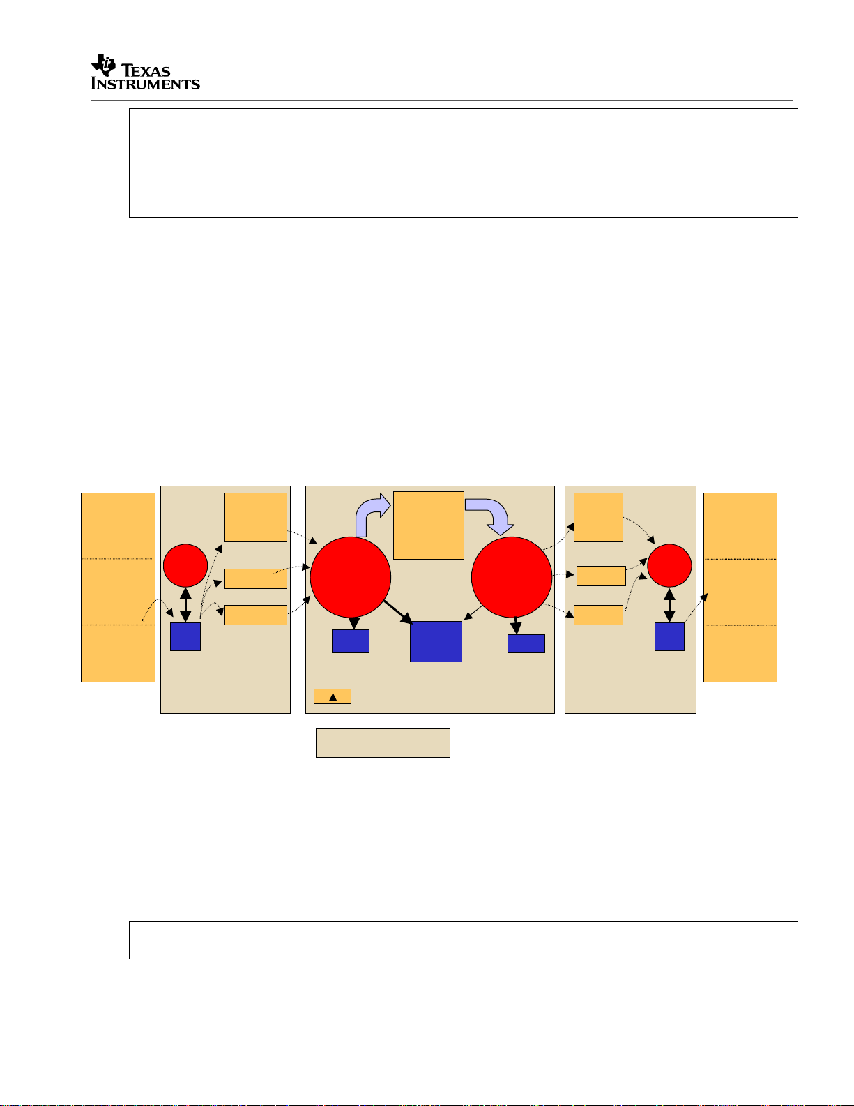
Figure 3 shows the task partitioning added to the application flow in Figure 2.
Device
Driver
Buffer
3 frames
Yuv
422to
420
scratch1
14 KB = 20 lines
YAfter420
414 KB
CbAfter420
CrAfter420
207 KB
tskInput tskOutput
H.263
enc
6 KB
Instance
memory
tskProcess
bitBuf
512 KB
Shared
Scratch
92 KB
tskControl
Figure 3. Task Partitioning in the Modified Application
3.3 Querying the H.263 Encoder for Status
The third change made to the base application was the use of a run-time API call to query the
algorithm as to its status after each frame. The eXpressDSP algorithm standard (xDAIS) states
that algorithms should provide a control API such as the following.
H263ENC_cellControl(&(chanHandle->cellSet[CELLH263ENC]), IH263ENC_GETSTATUS,
(IALG_Status *) &encStatus);
H.263
dec
1.5 KB
Instance
memory
y
414 KB
Cr
CbArrau
Cb
207 KB
Yuv
422to
420
scratch2
14 KB
Device
Device
Driver
Driver
Buffer
Buffer
3 frames
3 frames
DSP/BIOS Real-Time Analysis (RTA) and Debugging Applied to a Video Application 9
Page 10

SPRAA56
This call returns a status structure of type IH263ENC_Status that contains the number of bits
sent to the encoder, the frame type, and other data.
The features implemented in the control API can vary widely from one algorithm to another. The
bitrate and frame type measured by this API may not be available with all third-party video
algorithms unless specifically requested. Thus, it is important that the encoder and decoder
algorithms used by your application have the necessary hooks to allow complete benchmarking
of the end application.
3.4 Controlling the Frame Rate
The final structural change made to the base example was the addition of a mechanism for
controlling the processing frame rate of the application. This change required the introduction of
some counters and a conditional statement to measure the number of frames skipped during the
last 30. The conditional statement is shown here:
if( DISPLAYRATE*(frameCnt-frameSkip) > frameCnt*frameRateTarget ) {
frameSkip++;
// Tell the capture routine we're done
SCOM_putMsg(fromProctoInput,&(thrProcess.scomMsgRx));
continue;
}
The condition requires that the ratio of the target frame rate to the display frame rate be the
same as the ratio of the number of frames currently shown to the number that should be shown
at the set target frame rate. If the counters indicate that the ratio is exceeded, then the current
captured frame will not be processed or displayed, prompting the display driver to re-display the
most recent frame.
The capture frame rate and display frame rate are left unchanged at DISPLAYRATE, which is
set to 30 frames for second in NTSC applications or 25 frames per second in PAL applications.
Because the capture driver is using external memory bandwidth to copy unused frames from the
video port FIFO to external buffers, it may be desirable or necessary to control the frame rate at
the driver to eliminate this overhead. The frame rate control allows you to quickly evaluate the
visual quality of an encoder and decoder when using a lower frame rate.
The frame rate target can be controlled at runtime from a GEL script. Code Composer Studio’s
General Extension Language (GEL) provides a message for script-based control of most of the
debugger functions available in CCStudio. You can also manipulate variables on the target using
GEL, though this briefly halts the processor to update the value.
The GEL file included with the modified application is h263rateControl.gel. It provides sliders
and dialog boxes to control bitrate, frame rate, and other application parameters. Its control is
implemented by manipulating flags and variables in a global structure visible to the
tskVideoProcess and tskControl tasks. The control task passes bitrate and frame rate control
messages to the processing task, while other manipulations are handled directly by
tskVideoProcess.
The remaining changes to the application are not structural in nature. Instead, they consist of
short API calls added for run-time benchmarking. These remaining modifications are therefore
described in the next section on RTA techniques.
10 DSP/BIOS Real-Time Analysis (RTA) and Debugging Applied to a Video Application
Page 11

4 RTA Techniques for Performance Measurement
The RTA techniques described in this section are largely application-specific calls to DSP/BIOS
RTA services via APIs in the run-time code. These API calls can be added to any application
without modifying its logical structure.
In the case of the video application, performance overhead of the RTA tools is expected to be
minimal because the calls are made at the frame rate of 30 or 25 Hz, or even in some cases
every 30 or 25 frames, a very slow rate when compared to the speed of the DSP. In applications
where the frame rate is faster than 30Hz—for example, voice or audio—less frequent calls to
RTA services may be preferable. You might display benchmarking statistics only every N
frames, where N results in a display period of about one half second.
See Appendix A: Performance Impact for information on measuring overhead.
4.1 Measuring Function Execution Time with the UTL Module
The first technique for benchmarking uses the UTL module from Reference Frameworks. The
UTL_stsStart and UTL_stsStop calls were inserted before and after functions of interest, and
UTL_stsPeriod was used in each of the three data tasks to measure the period of one complete
loop through each task. Because the UTL module acts as a wrapper for DSP/BIOS STS objects,
the STS objects needed to be created during DSP/BIOS configuration. The following naming
convention is used to create the statistics objects:
SPRAA56
“sts” + task pseudonym + function benchmarked
The appInstrument.tci Tconf configuration script contains the following loop that creates these
STS objects. For example, the stsProcCell0 STS object is created for the first processing
function (cell 0) in the process task.
/* Array of string names to be used to create STS objects */
var stsNames = new Array("InVid", "OutVid", "Proc");
var stsStruct = new Array(
new Array("BusUtil", "Cell0", "Period", "Total", "Wait0"),
new Array("BusUtil", "Cell0", "Period", "Total", "Wait0"),
new Array("BusUtil", "Cell0", "Cell1", "Period", "Total", "Nframes")
)
/* STS objects for use with UTL_sts* functions */
for (i = 0; i < APPSTSTIMECOUNT; i++) {
for (j = 0; j < stsStruct[i].length; j++) {
var stsTime = tibios.STS.create("sts" + stsNames[i] + stsStruct[i][j] );
if(stsStruct[i][j] != "BusUtil") {
stsTime.unitType = "High resolution time based";
stsTime.operation = "A * x";
} else {
stsTime.unitType = "Not time based";
stsTime.operation = "Nothing";
}
}
}
The Tconf scripts are used to generate the DSP/BIOS configuration CDB file at design time,
which in turn links the appropriate kernel modules into the executable image during a build.
DSP/BIOS Real-Time Analysis (RTA) and Debugging Applied to a Video Application 11
Page 12

SPRAA56
4.2 Measuring Task Scheduling Latencies
Scheduling latency is defined as the time between a wakeup signal (semaphore post) to a
pending task and the actual start of that task's execution.
DSP/BIOS provides a mechanism for measuring scheduling latency with the TSK_settime and
TSK_deltatime APIs. These functions accumulate the difference in time from when a task is
made ready to the time TSK_deltatime is called. The placement of the TSK_deltatime API
therefore determines what is actually measured. Scheduling latency can be measured by
placing the API directly after the task’s blocking call, which may be MBX_pend, SCOM_getMsg,
or a similar API.
Time differences are accumulated in each task's internal STS object, so there is no need to
create a separate STS object to measure scheduling latency.
This technique is used for each task in the instrumented application. For example, in the input
task, the beginning of the run-time loop contains a call to TSK_deltaTime as follows:
while(1) // Tsk main processing loop begins
{
/* TSK_deltatime called immediately after last blocking call,
to measure scheduling latency */
TSK_deltatime(TSK_self());
...
SCOM_getMsg(fromProctoInput, SYS_FOREVER); /* end of main processing loop */
...
}
4.3 Measuring End-to-End Latencies
End-to-end latency is the time between the capture of a video frame in real-time, and the display
of that same video frame some number (T) of milliseconds later. Long latencies are undesirable
in bi-directional video applications, such as in a video conferencing systems. Such latency
causes delays between questions and responses, and makes conversation difficult. In media
playback systems, the tolerance for latency is usually higher.
In the example application, encode and decode occur within the same system. However, in
many designs the encoder and decoder could be part of separate systems. To accurately
measure latency, you need a method of indicating frame numbers and types and a method of
measuring latency on both ends of the system. This example application provides frame
numbering and identification as I or P frames, as well as a rudimentary measurement of latency
from input to output.
The code to implement the latency measurement is divided into two sections. The first section
makes a timestamp for a frame if the latency measurement has been completed for the
previously timestamped frame. This code section is included in the video input task:
// measure input to output frame latency
if (benchCapVid.captodisplay.done) {
benchCapVid.captodisplay.frameNum = frameCaptureCnt;
benchCapVid.captodisplay.latency = CLK_getltime();
benchCapVid.captodisplay.done = 0;
}
12 DSP/BIOS Real-Time Analysis (RTA) and Debugging Applied to a Video Application
Page 13

SPRAA56
The low-resolution CLK_getltime API is used instead of the high-resolution CLK_gethtime
because the range of the latency is known to be on the order of one or more frame times, where
a frame time is 33.33 ms in NTSC systems. The low-resolution timing measurement provided by
CLK_getltime is more cycle efficient and is in milliseconds. Since the data is displayed in
milliseconds, the lower-resolution time base results in a faster measurement, with sufficient
accuracy for the latency benchmark.
The corresponding code in the video output task finishes the benchmark once the frame has
propagated through the system:
if (!benchCapVid.captodisplay.done) { // benchVideoDisRta.captodisplay
benchCapVid.captodisplay.latency
= CLK_getltime() - benchCapVid.captodisplay.latency;
// current time - last captured frame timestamp = latency
UTL_logDebug2("Latency = %d [ms], for frame %d ", benchCapVid.captodisplay.latency,
benchCapVid.captodisplay.frameNum );
benchCapVid.captodisplay.done = 1;
}
Note that this measurement does not include the latency introduced by the capture and display
drivers. Similar techniques could be applied, using the UTL or STS APIs, to measure the driver
latency, however this would require modifying and rebuilding the driver, which is outside the
scope of this application note. To measure the total input-to-output latency, add the driver
latencies to the measured benchmark reported here.
4.4 Measuring the Frame Rate
Frame rate is the rate, in frames per second or Hz, of the capture, processing, or display of
video frames by the system. In video systems it is possible for the display frame rate to exceed
the capture and/or processing frame rate, so it is often important to measure it separately for the
capture, processing, and display stages in the data stream.
In this example application, the actual frame rate is measured at each stage, and user control of
the frame rate is provided for the processing stage.
During periods of peak CPU loading, the processing rate of the DSP can fall below the display
rate of the output device, resulting in dropped frames. Dropped frames are frames that were
received during capture or decode but not displayed, or frames that were captured but not
encoded. Frame dropping can occur when the CPU is overloaded by the processing required for
real-time encoding or decoding.
The VPORT display driver from the DDK is written to handle this condition gracefully. If a new
frame is not received from the application in time for the video port to display it, the device driver
continues to show the previously displayed frame. With high-motion video, this condition can
sometimes result in noticeable “jerkiness”. At other times, dropped frames can be difficult to
detect or quantify, so a method of detecting dropped frames is useful during development,
debugging, and demonstrations. A method for detecting dropped frames is implemented in this
application using the UTL and CLK services.
The following code from the tskProcess function measures the number of dropped frames by
subtracting the reference time from the actual time required to capture 30 or 25 frames. The
reference time should be approximately 1 second for NTSC or PAL systems, respectively.
DSP/BIOS Real-Time Analysis (RTA) and Debugging Applied to a Video Application 13
Page 14

SPRAA56
last30frame.current = CLK_getltime();
// check to see if we dropped any frames
benchVid.framesDropped.current = last30frame.current - last30frame.previous;
benchVid.framesDropped.current -= 1000*(frameCnt / DISPLAYRATE);
benchVid.framesDropped.current /= DISPLAYRATE;
last30frame.previous = last30frame.current;
if (benchVid.framesDropped.current > 0 && frameRateTarget == DISPLAYRATE ) {
LOG_error("Dropped %d frames", benchVid.framesDropped.current);
UTL_logDebug2("Dropped %d frames, after %d frameCount",
benchVid.framesDropped.current, frameProcessCnt);
benchVid.framesDropped.previous = benchVid.framesDropped.current;
if (benchVid.framesDropped.current > benchVid.framesDropped.max) {
benchVid.framesDropped.max = benchVid.framesDropped.current;
}
} // end of dropped frame detection
A UTL_logDebug API call is made during the benchmarking routine every 30 or 25 frames, to
report any dropped frames during the last group. Additionally, a call to LOG_error is made,
which will insert a red mark in the DSP/BIOS execution graph and insert the text string specified
in the API into the execution graph details, which are visible from the Message Log RTA tool.
4.5 Simulating High CPU Load Stress Conditions with Dummy NOP Loads
The H.263 encoder algorithm in this example has a relatively moderate CPU load benchmark of
about 50%. Other applications may require encoders with higher CPU loading or additional postprocessing stages that add to the load. Before integrating such functions into the system, you
may want to estimate their effects on real-time performance.
One way to estimate the effects of an additional load is with a dummy load of NOP instructions.
Such a dummy load function is provided in the dummyLoad.c file of this example. It can be
controlled from the h263rateControl.gel file, which manipulates the
controlVideoProc.dummyProcessLoad variable containing the number of NOP instructions the
function will execute. The dummy load function can also be used to test a system beyond typical
stress conditions to ensure that it performs correctly, and drops frames gracefully if necessary.
4.6 Programmatic Measurement of Total CPU Load
The DSP/BIOS Real-Time Analysis (RTA) tools already provide a CPU Load Graph tool within
CCStudio on the host PC. However, some applications could benefit from an awareness of the
CPU load within the program itself. A program with awareness of the current CPU load, for
instance, could decide not to instantiate new processing routines when the load is high, or could
turn on additional post-processing when the load is lower.
Programmatic calculation of the CPU load could also be useful if RTA is disabled, causing the
CPU Load Graph to be inoperative. The application could periodically report the current CPU
load using the UTL_logDebug APIs, and that data could be viewed at a breakpoint or halt.
This application note introduces a LOAD module that allows you to check the CPU load via an
API call. That data is reported during benchmark output in the processing task. Figure 4 shows
how the LOAD module works.
14 DSP/BIOS Real-Time Analysis (RTA) and Debugging Applied to a Video Application
Page 15

SPRAA56
‘
p))
App
t0 t1 t0 t1
minloop’ (in units of ~ cycles)
‘count’ is # hits of
LOAD_idlefxn in the
window
100 – IDLload gives
CPU Load
The LOAD module relies on an IDL thread to be inserted in an application to calibrate the
amount of time needed to run a single iteration of the DSP/BIOS idle loop. It estimates the CPU
load by dividing the idled time by the time elapsed and subtracting the result from 1. The load is
multiplied by 100 and reported as a percentage.
To use the LOAD module in a project, follow these steps:
1. Configure an IDL function that calls LOAD_idlefxn. This routine runs in the background to
measure the time spent in the CPU’s IDL (background) loop and compares it with the time
spent outside the background loop to calculate a CPU load. The following Tconf statements
configure such an object.
var CpuLoadCheck = tibios.IDL.create("CpuLoadCheck");
CpuLoadCheck.fxn = prog.extern("LOAD_idlefxn");
2. Include load.c and load.h in the project.
3. Call LOAD_getcpuload as needed within your application:
thrProcRta.cpuLoad = LOAD_getcpuload();
Window = 500ms (default)
cpuload = (100 - ((100 * (count * minloo
/ total))
Figure 4. CPU Load Measurement at Run-Time
IDL load
The project keeps track of the number of times the idle loop is entered over a time period
specified by the “window” variable in load.c. The CPU load reported by LOAD_getcpuload is the
load during the previous window period. You can modify the value of the "window" variable to
suit the variability of the CPU load in your application.
Because the LOAD_idlfxn routine is only called during the background loop, while all other tasks
in the system are presumably blocked or not ready, the only load introduced by this module is
the execution time of the call to LOAD_getcpuload, which is approximately 1200 instruction
cycles.
4.7 Memory Bus Utilization
Processor utilization is a measurement of the DSP resources consumed by a given task,
algorithm, or function. It is more than just MIPS consumption, however, since memory bus
utilization is an important component of processor utilization, particularly when working with
high-resolution video (greater than 720x480).
DSP/BIOS Real-Time Analysis (RTA) and Debugging Applied to a Video Application 15
Page 16

SPRAA56
Y
Y
Y
YY Y
Y
YYY
Y
Y
In video applications that handle the full resolution of 720x480, each from contains about 675 KB
of data. Such applications must constantly move video frames from internal working memory
buffers to external frame buffers and back. This often results in several MB of memory transfers
through the external bus for each frame. At 30 frames per second, the memory transfer
bandwidth requirement can be a significant CPU resource requirement. As resolutions increase
to high-definition sizes of 1440x720 or even 1920x1080, and frame rates may be 60 frames per
second, the memory bandwidth requirement can be even more of a limitation than CPU cycles.
The architecture of the video software framework often determines the amount of memory
bandwidth required. Frameworks that repeatedly move video frames from external memory to
internal working buffers and back introduce unnecessary memory bandwidth overhead that may
limit the frame rate. Therefore, it is important to understand the memory bus utilization of the
whole system and its components.
Data structures for measuring the memory bus utilization of the input, processing, and display
tasks are included in the modified example. The actual values logged into the data structures
are estimated, based on the defined size of the frames being moved to internal buffers for
processing.
For the case of YUV4:2:0 to YUV4:2:2 color conversion, the external memory bus utilization and
data flow is shown in Figure 5. A D1 frame (345,600 bytes of luminance data) and 2 chroma
buffers of ¼ that size are copied to internal memory sections for processing, totaling 1.5 times a
frame worth of data. The data copied back out to external memory after conversion has twice as
many chroma samples, for a total of 2 times a D1 frame size in pixels. The estimated total bus
utilization is therefore 1.5N + 2N bytes, where N is the frame size in pixels.
Y Y Y Y
Cb
86,400 B
Y Y
Y Y
Y
Y
Y Y Y Y
Cb
Cb Cb
Cr Cr
86,400 B
Cr
Cr
external memory
Figure 5. External
720*480 = 345,600 B
internal L2
memory
345,600 B
172,800 B
172,800 B
Y Y
Y
Y Y
Cb
Cb
Cb Cb
Cr Cr
Cr
Cr
Cb Cb
Cb Cb
Cr Cr
Cr
14,400 B
scratch
external memory
Internal Memory Transfers, YUV4:2:0 to 4:2:2 Conversion Function
↔
Y
Cr
16 DSP/BIOS Real-Time Analysis (RTA) and Debugging Applied to a Video Application
Page 17

SPRAA56
These estimates are fairly accurate for the color conversion functions in the input and display
tasks, but the estimates are less accurate for the encoder and decoder algorithms in the
processing task. Ideally, the memory bus utilization should be available in the status structure or
estimated on the data sheet of an algorithm. It is recommended that you request this information
from third-party algorithm providers during application development, particularly for applications
above D1 (720x480) resolution.
The estimates of the memory bus utilization of the algorithms and major functions in the system
are defined in rtaVideodebug.h as:
#define EST_ENCODE_BUSUTIL_IN_FRAMES 2.5
#define EST_DECODE_BUSUTIL_IN_FRAMES 2.5
#define EST_CAP_BUSUTIL_IN_FRAMES 3.5
#define EST_DIS_BUSUTIL_IN_FRAMES 3.5
The number 2.5 * frame size (in pixels) was chosen for the encoder and decoder as an estimate
of the bus utilization. Actual values may vary, so you can modify this estimate, or can replace it
with an actual calculation if the algorithm can provide that data in its status structure.
The bus utilization benchmarks are reset by the benchmarking routines every 30 frames, and
are logged to the STS object named sts+”task”+BusUtil for viewing in the DSP/BIOS Statistics
View tool. This results in a bus utilization statistic in bytes per second.
4.8 Bitrate and Frame Type
Bitrate is important in applications that do encoding or decoding. The bitrate of encoded video
often varies greatly with different video content, increasing to high values during periods of high
motion and image complexity, and decreasing to low values during relatively still video with less
image complexity. Encoder applications must trade off bitrate for quality, so the capability to
accurately measure and monitor bitrate is an important tool for video system designers.
This example provides a mechanism for real-time bitrate measurement and control. This is
possible because the H.263 encoder algorithm used by the application allows control and
monitoring of the bitrate.
#ifdef RTA_INCLUDED
while( MBX_pend( &mbxProcess, &rxMsg, 0) ) // poll with zero timeout value, which
// returns zero right away if no message is available
{
switch(rxMsg.cmd) {
case BITRATECHANGED:
h263encParams.bitRate = rxMsg.arg2; // controlVideoProc.bitRateTarget from GEL
H263ENC_cellControl(&(chanHandle->cellSet[CELLH263ENC]), IH263ENC_SETPARAMS,
(void *)&h263encParams);
break;
case FRAMERATECHANGED:
frameRateTarget = rxMsg.arg2; // controlVideoProc.bitRateTarget from GEL
h263encParams.frameRate = frameRateTarget;
H263ENC_cellControl(&(chanHandle->cellSet[CELLH263ENC]), IH263ENC_SETPARAMS,
(void *)&h263encParams);
break;
}
} // end polling of MBX
#endif // #ifdef RTA_INCLUDED
DSP/BIOS Real-Time Analysis (RTA) and Debugging Applied to a Video Application 17
Page 18

SPRAA56
Most current encoders use three primary frame types: Intracoded frames, Predicted frames, and
Bidirectional predicted frames. These are referred to as I, P, and B frames. The H.263 encoder
supplied with the example application encodes I and P frames only, but you can configure the
ratio of I to P frames. Often this ratio is used in the quality vs. bitrate tradeoff. The H.263
encoder has hooks to allow for monitoring or selecting the frame type. This example application
only monitors the frame type, and can be configured to display benchmark information on every I
frame, for example.
Hooks for manipulating the Q (quantization) factor are provided with the H.263 algorithm in this
example, but they are not modified after startup in this example. The encoder does not provide
hooks for viewing statistics on the actual Q factor, so although this benchmark may be desirable
in many applications, its measurement is not possible unless the algorithm provider provides API
access to its status.
For many video applications, the encoders and decoders are purchased from third parties. The
level of visibility and control accessible via APIs should be a factor considered when choosing
algorithms, depending on the system's needs for control and benchmarking. Some applications
require minimal control of the encoder (for example, to set the target bitrate), while other
applications require more advanced control.
The percentage of macroblocks that are intracoded is another benchmark that could potentially
be useful. Some encoders can report this benchmark, but the H.263 encoder algorithm used in
this application does not. This number is the percentage of blocks for which no suitable motion
vector could be found to describe the motion of that block from its location in a previous frame.
When a macroblock is intracoded, it is encoded independently of any other frame, as opposed to
being encoded as a difference from a block in a previous frame. The larger the percentage of
macroblocks intracoded, the higher the CPU performance required to encode that frame. A high
percentage often occurs for video with rapid movement or scene changes.
4.9 Methods for Transmitting Measured Performance Data
In the modified example, variables to enable benchmarking are contained in a single data
structure for each stage: benchVideoCapRta, benchVideoProcRta, and benchVideoDisRta. The
benchmarking structure for processing is shown below:
typedef struct BenchVideoProcRta {
BenchTime timeProcess;
BenchTime timeLastIframe;
BenchTime busUtilization;
BenchTime bitBucketSize;
BenchVal frameProcessCount;
Int frameType;
BenchVal controlledFrameSkip;
BenchVal framesDropped;
BenchVal cpuLoad;
} BenchVideoProcRta;
Similar structures are defined for run-time control of processing, and for benchmarking the
capture and display tasks. An instance of the BenchVideoProcRta structure type is declared
globally in tskProcess.c for use by the benchmarking routines.
18 DSP/BIOS Real-Time Analysis (RTA) and Debugging Applied to a Video Application
Page 19

The benchmarking routines send out selected benchmark data at a prescribed interval: every
th
frame, every I (Intracoded) frame, or only on a dropped frame. The interval can be selected
30
by controlling the .rtaMode variable within the control structure.
Benchmark data is transmitted to the CCStudio on the host PC via RTDX (Real-Time Data
eXchange), which is used behind the scenes by the DSP/BIOS RTA tools. RTDX allows Code
Composer Studio to read from or write to target buffers in DSP addressable memory at run-time.
For example, the UTL_logDebug2 API command use RTDX to move two variables and a
message to the Message Log window available from the DSP/BIOS menu in CCStudio.
Although the channel used in this example is the standard debugging connection, data could be
sent over any channel with sufficient bandwidth to an endpoint where you can view the data. For
example, the benchVideoProcRta data structure could be sent over Ethernet in a networked
encoder or decoder application to provide statistics to a third-party receiving application.
The current size of the debug structure is small (defined in Appendix A), so sending the structure
once every 30 frames would introduce a negligible load on the system and the network, yet
could still provide useful information at that rate.
4.10 Application-Specific Control via GEL Scripts in CCStudio
As mentioned earlier, run-time control is provided by the h263rateControl.gel script. The menu
item controls in the script allow you to manipulate the global benchVideoProcRta structure from
the host PC.
menuitem "Rate Control --bitrate-framerate";
slider setFrameRate(0, 30, 1, 1, framerate)
{
controlVideoProc.frameRateChanged = 1;
controlVideoProc.frameRateTarget = framerate;
}
SPRAA56
For details on the GEL language and its functions, see the “Using the Integrated Development
Environment” section of the Code Composer Studio online help.
5 Viewing Benchmarks in the Instrumented Application
Now that we have described the available benchmarks, this section tells how to measure those
benchmarks while running the application.
5.1 Requirements
To run the application supplied with this note, you need the following components:
• DM642 EVM and Board Support Package
• CCStudio v2.21 or greater
• JTAG emulator
• Input video source – composite or S-Video
• Video display – composite or S-Video
DSP/BIOS Real-Time Analysis (RTA) and Debugging Applied to a Video Application 19
Page 20

SPRAA56
The application supplied with this note references board support software and libraries installed
with the DM642 EVM. The project options assume this software is installed in
$TI_DIR$\boards\evmdm642.
The project also references the H.263 encoder algorithm, which is provided as object code with
the DM642 EVM’s Board Support Package. Therefore, that package and all its associated
components must be installed before running or building the supplied example as delivered.
Tconf scripts have been provided to configure the application provided with this application note.
A batch file (makeConfig.bat) is provided to execute tconf on the provided configuration script.
Note: The TI_DIR environment variable must be defined and tconf.exe must be in your PATH.
These are defined in the DosRun.bat file provided in the CCStudio installation.
While the techniques used in this application are targeted at video applications, several
techniques can be used in any embedded DSP application, such as programmatic CPU load
measurement and scheduling latency measurement. Further, all the techniques are
implemented in C code or in APIs available for multiple TI DSP targets supported by DSP/BIOS,
so the concepts presented here are portable to targets other than the platform specified in the
requirements list.
5.2 Running the Application
1. Copy the h263loopback_rta.zip file to a working directory and extract its contents.
2. Open CCStudio, and open the h263loopback_rta.pjt project.
The project file references all source and object files required to build the executable. Source
filenames with “_rta” at the end have been modified for this note. Source filenames without
that addition are unchanged from the base H.263 loopback example.
→
3. Choose the GEL
memory map for loading a program.
This command ensures that the DM642 EVM target is in a known stable condition for loading
code. The GEL reset command clears up the DSP memory map, initializes the external
memory interface, and clears any breakpoints previously set. You can review or change the
source code for the GEL reset file if necessary.
4. Load the h263loopback_rta.out program.
5. Start the video input and output devices.
6. Run the application. (Press F5, or choose Debug
A looped back redisplay of the video input should appear on the video output display.
7. Choose File
that contains the .pjt file.
→
Reset command to clear any breakpoints and prepare the EMIF and
→
Run from the menus.)
Load GEL and load the h263RateControl.gel file from the same directory
This application-specific GEL script allows you to control of the frame rate, bitrate, and other
parameters discussed earlier in this application note.
8. Open the following DSP/BIOS RTA tools from the DSP/BIOS menu in CCStudio. Figure 6
shows CCStudio with the following windows open.
20 DSP/BIOS Real-Time Analysis (RTA) and Debugging Applied to a Video Application
Page 21

SPRAA56
– Statistics View. Shows the values for STS objects used by the UTL benchmarking APIs
and some TSK-specific STS objects. You may want to change the units of the STS
objects to milliseconds. To do this, right-click on the Statistics View and choose
Properties. You can change the units and disable/enable STS objects individually. (The
IDL_busyObj is used by the CPU Load Graph, you can disable its statistics and the
TSK_idle statistics.)
– Message Log. Shows output from the LOG_printf and UTL_logDebug APIs. Most
benchmarking techniques in this example send output to the Message Log, so this may
be the most important RTA window for debugging and benchmarking. Because of the
large amount of data sent to this window, you may want to configure the window to
automatically move to the end of the log to display the most recent data. To do this,
right-click on the Message Log and choose “Automatically scroll to end of buffer”. You
can also send log data to a file on the PC. To do this, right-click on the Message Log
and select Properties. Then enable and select the file.
– CPU Load Graph. Shows the percentage utilization of the DSP core in non-idle tasks.
– RTA Control Panel. You may want to lower the update (polling) rate of the real-time
windows; this makes the instrumentation less intrusive. Right-click on the RTA control
panel and choose Properties. You can change the update rates of various RTA
windows, starting from a default rate of 1 second. A rate of 3-5 seconds is
recommended.
– Execution Graph. (optional) Displays the execution flow of TSKs in the system. This
graph can indicate whether TSKs are executing in the correct sequence and not stalling.
In an application that is working correctly, the Execution Graph may not be useful. In an
application with a run-time error, this graph can help indicate whether the correct
execution sequence occurs.
Hint: To better organize a large number of debugging windows on the screen, you may want
to float each window in the CCStudio workspace. To do this, right-click on a window, then
select “Float in Main Window”.
Note: With the current revision of the 'C64x CPU, real-time analysis can “freeze” and stop
updating in real-time. If you experience this problem, see the SDSsq27324 problem report
and workaround.
After opening all these windows, CCStudio may look like Figure 6.
DSP/BIOS Real-Time Analysis (RTA) and Debugging Applied to a Video Application 21
Page 22

SPRAA56
Figure 6. Workspace Including RTA Windows
5.3 Interpreting the Benchmarks
There are a total of 20 statistics measured by the application: 16 application-specific STS
objects and 4 objects created automatically with the TSKs. Figure 7 shows a sample Statistics
View of all these measurements.
22 DSP/BIOS Real-Time Analysis (RTA) and Debugging Applied to a Video Application
Page 23

SPRAA56
Figure 7. Statistics View Showing Benchmark Measurements
Look at both the average values and the maximum values to see how the application
benchmarks are performing.
Note that STS objects hold 32-bit values on the target DSP. The values accumulated on the host
PC are 64-bit values. The values on the target DSP are reset to zero when the host PC polls
them for data. So, it is possible for the total value to overflow and restart at zero if you choose a
slow update rate for the Statistics View in CCStudio. The maximum value is still accurate even if
the total overflows. The average value is calculated on the host PC, and is not stored in the STS
objects on the target DSP.
5.3.1 Expected Values for the STS Objects
Table 1 shows expected and measured values for the STS benchmarks in the instrumented
application. The right column is blank in case you want to fill in your own measurements.
stsInVidPeriod, stsOutVidPeriod, and stsProcPeriod are all expected to be 33.33 ms, because
this is the amount of time between successive frames in an NTSC video system.
The stsInVidTotal, stsOutVidTotal, and stsProcTotal values are expected to be slightly more
than the sum of the Cell functions in each task, because the API calls are placed around a larger
block than just the algorithm execution calls. The total values do not include time waiting on
blocking calls like FVID_exchange or SCOM_getMsg, however.
The waiting time for the input and output tasks (stsInVidWait0 and stsOutVidWait0) are expected
to be some value less than 33 ms, with a longer waiting time for the display than for the input.
DSP/BIOS Real-Time Analysis (RTA) and Debugging Applied to a Video Application 23
Page 24

SPRAA56
In the input and output tasks, Cell0 is the color conversion routine. In the processing task, Cell0
is the encoder and Cell1 is the decoder. The expected values for color conversion routines are
given as 2-5 ms, typical values for an optimized color conversion routine. Where no expected
value was available, the expected value is "—".
STS Benchmark Expected Value Measured Value Your Measurement
tskInput 100s of cycles 60,472 instructions
tskOutput 100s of cycles 11,482,597 instructions
tskVideoProcess 100s of cycles 24,308 instructions
tskControl 100s of cycles 702,097 instructions
stsInVidPeriod 33.33ms 33.26 ms
stsInVidTotal — 1.95 ms
stsInVidCell0 2-5ms 1.95 ms
stsInVidWait0 <stsOutVidCell0> 4.75 ms
stsInVidBusUtil — 28,512,000 Bps
Table 1. Expected and Measured STS Benchmarks
stsOutVidPeriod 33.33ms 33.29 ms
stsOutVidTotal — 2.43 ms
stsOutVidCell0 2-5ms 2.41 ms
stsOutVidWait0 <33ms 30.35 ms
stsOutVidBusUtil — 28,512,000 Bps
stsProcPeriod 33.33ms 33.26 ms
stsProcTotal Cell0 + Cell1 24.07 ms
stsProcCell0 — 18.97 ms
stsProcCell1 — 5.09 ms
stsProcNframes 1 second (30 frames) 498.84 ms
stsProcBusUtil — 26,926,600 Bps
The typical expected values for task scheduling latency are on the order of a few hundred
cycles, so those benchmarks were gathered in units of instructions rather than milliseconds.
Because of the architecture of the video example, where the data tasks all have equal priority,
the processing and output task can spend significant time waiting on tasks that are already
running. This skews the scheduling latency benchmark higher for all three of the data stream
tasks (tskInput, tskOutput, and tskVideoProcess). This can be observed in the Execution Graph
by noting the amount of time the tasks remain in the ready state while waiting for currently
executing tasks to complete.
24 DSP/BIOS Real-Time Analysis (RTA) and Debugging Applied to a Video Application
Page 25

5.3.2 Expected Values Delivered to the Message Log
CPU load, latency, time to process 30 frames, and bitrate are all sent to the Message Log rather
than the Statistics View window. Table 2 shows the expected and measured values.
Table 2. Expected and Measured Logged Benchmarks
Benchmark Expected Value Measured Value Your Measurement
latency <33 ms 26 ms
CPU load 80-90% 84-86%
bitrate 4084 kbps 4009-4117 kbps
Time to process 30 frames 1 second 1001-1004 ms
5.4 Controlling the Run-Time Parameters Dynamically
After running the application on the EVM and gathering benchmarks, you may want to measure
benchmarks and test operation with different frame rates, bitrates, or configurations. You can
→
control such parameters at run-time through the GEL
Some of the commands are:
• setFrameRate. Use this slider to set the frame rate to a value from 0 to 30.
h263rateControl menu commands.
SPRAA56
• setBitRate. Type a target bitrate for the encoder algorithm between 32 and 15000.
• passthroughReference. Set to 1 to bypasses the decoder and output the frame captured
by the encoder without any modification. Set to 0 to use the decoder.
• color. Set to 1 to enable color processing. Set to 0 to disable color processing. This slider
can be used to benchmark the application with and without color processing enabled.
5.4.1 Debug Mode
The amount of data displayed in the Message Log in the default configuration may be more than
what is required. By default, all benchmarks are reported every 30 frames. To control the
→
displayed data, choose GEL
1. ERRORS ONLY. This mode reports only dropped frames or other errors.
2. CPU LOAD ONLY. This mode displays only the CPU load and frame type every N frames.
3. EVERY N FRAMES. This mode displays more complete benchmarking every N frames,
including bitrate and frame skip reports.
4. EVERY I FRAME. This mode displays more complete benchmarking when an I
(intracoded) frame is encoded. The distance between I frames is an algorithm parameter
that is set to 132 by default, but can be changed at runtime to another value if necessary.
rtaMode and set the slider to one of the following 4 mode values:
DSP/BIOS Real-Time Analysis (RTA) and Debugging Applied to a Video Application 25
Page 26

SPRAA56
The value of N, which is used by modes 2 and 3, is 30 frames by default. As a result, RTA data
is logged every 1 second in NTSC applications. This value can be changed using the
→
GEL
the value by 30 before updating the control variable in the application. For PAL applications,
change the multiplier value in the GEL file to 25.
rtaWindow slider. This slider asks for a value between 1 and 10 seconds, and multiplies
5.4.2 Capture and Display Task Benchmarking
In addition to the RTA modes, you can enable or disable instrumentation in the capture and
display tasks using the USER0 and USER1 bits in the RTA Control Panel. They are turned on
by default. In order to view the latency from the input to output task, it is necessary to turn these
bits on. After a typical latency measurement is recorded, the amount of data the capture and
display tasks deliver to the Message Log may be more than is useful.
6 References
• H.263 Loopback on the DM642 EVM (SPRA933)
• The TMS320DM642 Video Port Mini-Driver (SPRA918)
• Reference Frameworks for eXpressDSP Software: RF5, An Extensive, High-Densit y
System (SPRA795)
• Reference Frameworks for eXpressDSP Software: API Reference (SPRA147)
• TMS320 DSP/BIOS User's Guide (SPRU423)
• TMS320C6000 DSP/BIOS API Reference Guide (SPRU403)
• DSP/BIOS TextConf User's Guide (SPRU007)
• DSP/BIOS Driver Developer's G uide (SPRU616)
26 DSP/BIOS Real-Time Analysis (RTA) and Debugging Applied to a Video Application
Page 27

Appendix A. Performance Impact
A.1 Overhead of Performance Measurement Techniques
Because most of the benchmarking APIs are called once every 30 frames, the additional CPU
load expected after adding the instrumentation is low. The measured performance of the
benchmarking techniques is given in Table 3. A spreadsheet containing the expected and actual
timing values is provided with the software distribution.
Table 3. Measured Performance of Benchmarking Techniques
SPRAA56
Execution Time
Benchmark
MBX check in process Task 3641 17112 0.00018205 1
LOAD module call 1182 2432 0.00000197 30
Single Call to UTL_stsStart 517 13968 0.00043945 16
Single Call to UTL_stsStop 325 488 0.00027625 16
Capture Task benchmarking 1848 15064 0.00000308 30
Display Task benchmarking 2288 7824 3.81333E-06 30
Process Task benchmarking 3196 18568 5.32667E-06 30
Control Task 1533 2856 0.00007665 ?
SubTotal Load (Task bchmrk) 7332 0.0003666 30
SubTotal Load (UTL calls) 13472 0.0006736 30
Total Load of benchmarking 17357.4 0.00086787 1
(Avg) [instr]
Execution Time
(Max) [instr] CPU Load
Execution Rate
[per N frames]
These benchmarks are given in instructions, and the individual CPU load of each function is
calculated by dividing the benchmark by 20M instructions per frame, the number of cycles
available on a 600 MHz 64x device in a 30 fps NTSC system.
These benchmarks were measured using UTL_stsStart and UTL_stsStop API calls bracketing
the regions of code to be benchmarked. For example, to benchmark the LOAD_getcpuload
function, the measurement code was the following:
UTL_stsStart( stsBenchmark1 );
benchVid.cpuLoad.current = LOAD_getcpuload();
UTL_stsStop( stsBenchmark1 );
This method of benchmarking allows execution time to be measured in real-time, although if an
interrupt or context switch occurs between the UTL calls, the time spent executing the interrupt
or out-of-context code would also be included in the benchmark.
A.2 RTA Effects on CPU Load
The CPU load was measured with RTA debugging turned off and the UTL_DBGLEVEL set to
40. The total CPU load of the application with the instrumentation turned off was 93% average
and 95% peak. The CPU load of the instrumented application was 93% average and 95% peak
when using the same video content, a repeating high-motion sequence from a DVD. The
benchmarking did not make a statistically significant impact on the CPU load.
DSP/BIOS Real-Time Analysis (RTA) and Debugging Applied to a Video Application 27
Page 28

SPRAA56
A.3 Memory Footprint
The total additional code size added to the application for the debugging features was 29 KB of
external memory. This was calculated from the size of the .out file with benchmarking added
(518 KB) and without benchmarking (491 KB).
All the footprint numbers in this appendix were obtained under the following conditions (expect
where noted):
• Platform: EVMDM624
• Debug flags:
-g –ml3 -d"UTL_DBGLEVEL=70" -d"_DEBUG" -d"RTA_INCLUDED" -d"_NTSC" -d"CHIP_DM642" -ml3 -mv6400
• Optimization: -o2
• DSP/BIOS: version 4.90.27
• RDTX: enabled
• LOG buffers: 2 * 4096(buffer size) + 1 * 256(buffer size) = 8448(8-bit bytes)
The real-time analysis footprint numbers in Table 4 were obtained using the setup described in
Section 5.1, Requirements. All sizes are in 8-bit bytes.
Code Size
Data Size
Bss + Stack
Total
Code Reduction
Relative to Case # 1
Data Reduction
Relative to Case # 1
Each STS object adds a one-time code size of 128 bytes plus an additional 16 bytes of data
space. The STS objects are not removed in any cases in the table above. In this application, the
total footprint impact due to STS objects is 496 bytes. (All bytes here are 8-bit bytes.)
Table 4 shows that the impact on space, especially code space, by real-time analysis
instrumentation is negligible relative to the application size.
Table 4. Memory Footprint Details
All RTA Features
Enabled (as
shipped)
11,406,788 11,405,076 11,402,856 11,401,272
3347 3347 2643 2643
5392 5392 5392 5392
11,415,527 11,413,815 11,410,891 11,409,307
----
---- 0 (0%) 704 (21% reduction) 704 (21% reduction)
Remove
–D"RTA_INCLUDED"
Build Option
1712
(0.015% reduction)
Remove UTL Calls
(Set
UTL_DEBUGLEVEL=0)
3932
(0.034% reduction)
Remove Both
–D"RTA_INCLUDED"
Build Option and
UTL Calls
5516
(0.048% reduction)
28 DSP/BIOS Real-Time Analysis (RTA) and Debugging Applied to a Video Application
Page 29

IMPORTANT NOTICE
Texas Instruments Incorporated and its subsidiaries (TI) reserve the right to make corrections, modifications,
enhancements, improvements, and other changes to its products and services at any time and to discontinue
any product or service without notice. Customers should obtain the latest relevant information before placing
orders and should verify that such information is current and complete. All products are sold subject to TI’s terms
and conditions of sale supplied at the time of order acknowledgment.
TI warrants performance of its hardware products to the specifications applicable at the time of sale in
accordance with TI’s standard warranty . Testing and other quality control techniques are used to the extent TI
deems necessary to support this warranty . Except where mandated by government requirements, testing of all
parameters of each product is not necessarily performed.
TI assumes no liability for applications assistance or customer product design. Customers are responsible for
their products and applications using TI components. T o minimize the risks associated with customer products
and applications, customers should provide adequate design and operating safeguards.
TI does not warrant or represent that any license, either express or implied, is granted under any TI patent right,
copyright, mask work right, or other TI intellectual property right relating to any combination, machine, or process
in which TI products or services are used. Information published by TI regarding third–party products or services
does not constitute a license from TI to use such products or services or a warranty or endorsement thereof.
Use of such information may require a license from a third party under the patents or other intellectual property
of the third party , or a license from TI under the patents or other intellectual property of TI.
Reproduction of information in TI data books or data sheets is permissible only if reproduction is without
alteration and is accompanied by all associated warranties, conditions, limitations, and notices. Reproduction
of this information with alteration is an unfair and deceptive business practice. TI is not responsible or liable for
such altered documentation.
Resale of TI products or services with statements different from or beyond the parameters stated by TI for that
product or service voids all express and any implied warranties for the associated TI product or service and
is an unfair and deceptive business practice. TI is not responsible or liable for any such statements.
Mailing Address:
Texas Instruments
Post Office Box 655303
Dallas, Texas 75265
Copyright 2004, Texas Instruments Incorporated
 Loading...