

Page 1

User’s Guide
July 2002 Advanced Analog Products
SLUU083A
Page 2

IMPORTANT NOTICE
Texas Instruments Incorporated and its subsidiaries (TI) reserve the right to make corrections, modifications,
enhancements, improvements, and other changes to its products and services at any time and to discontinue
any product or service without notice. Customers should obtain the latest relevant information before placing
orders and should verify that such information is current and complete. All products are sold subject to TI’s terms
and conditions of sale supplied at the time of order acknowledgment.
TI warrants performance of its hardware products to the specifications applicable at the time of sale in
accordance with TI’s standard warranty . Testing and other quality control techniques are used to the extent TI
deems necessary to support this warranty . Except where mandated by government requirements, testing of all
parameters of each product is not necessarily performed.
TI assumes no liability for applications assistance or customer product design. Customers are responsible for
their products and applications using TI components. T o minimize the risks associated with customer products
and applications, customers should provide adequate design and operating safeguards.
TI does not warrant or represent that any license, either express or implied, is granted under any TI patent right,
copyright, mask work right, or other TI intellectual property right relating to any combination, machine, or process
in which TI products or services are used. Information published by TI regarding third–party products or services
does not constitute a license from TI to use such products or services or a warranty or endorsement thereof.
Use of such information may require a license from a third party under the patents or other intellectual property
of the third party , or a license from TI under the patents or other intellectual property of TI.
Reproduction of information in TI data books or data sheets is permissible only if reproduction is without
alteration and is accompanied by all associated warranties, conditions, limitations, and notices. Reproduction
of this information with alteration is an unfair and deceptive business practice. TI is not responsible or liable for
such altered documentation.
Resale of TI products or services with statements different from or beyond the parameters stated by TI for that
product or service voids all express and any implied warranties for the associated TI product or service and
is an unfair and deceptive business practice. TI is not responsible or liable for any such statements.
Mailing Address:
Texas Instruments
Post Office Box 655303
Dallas, Texas 75265
Copyright 2002, Texas Instruments Incorporated
Page 3

About This Manual
Trademarks
Preface
Read This First
This user’s guide describes the bq2400x evaluation module. The EVM conve-
niently evaluates a linear Li-ion bq2400x charge-management solution for
one- and two-cell battery-pack applications. This guide describes a complete
designed-and-tested charger, which delivers up to 1.2 A of continuous-charge
current for one- or two-cell applications
How to Use This Manual
This document contains the following chapters:
- Chapter 1—Introduction
- Chapter 2—Test Summary
- Chapter 3—Physical Layouts
- Chapter 4—Bill of Materials
- Appendix A—Schematic
Related Documentation From Texas Instruments
- bq24001, bq24002, bq24003 data sheet, literature number
SLUS462A
- bq24004, bq24005, bq24006 data sheet, literature number
SLUS476
Trademarks
PowerPAD is a trademark of Texas Instruments.
Read This First
iii
Page 4

Running Title—Attribute Reference
Contents
1 Introduction 1-1. . . . . . . . . . . . . . . . . . . . . . . . . . . . . . . . . . . . . . . . . . . . . . . . . . . . . . . . . . . . . . . . . . . . .
1.1 Background 1-2. . . . . . . . . . . . . . . . . . . . . . . . . . . . . . . . . . . . . . . . . . . . . . . . . . . . . . . . . . . . . . . .
1.2 Performance Specification Summary 1-2. . . . . . . . . . . . . . . . . . . . . . . . . . . . . . . . . . . . . . . . . .
2 T est Summary 2-1. . . . . . . . . . . . . . . . . . . . . . . . . . . . . . . . . . . . . . . . . . . . . . . . . . . . . . . . . . . . . . . . . . .
2.1 Setup 2-2. . . . . . . . . . . . . . . . . . . . . . . . . . . . . . . . . . . . . . . . . . . . . . . . . . . . . . . . . . . . . . . . . . . . .
2.1.1 I/O Connections 2-2. . . . . . . . . . . . . . . . . . . . . . . . . . . . . . . . . . . . . . . . . . . . . . . . . . . . .
2.1.2 Jumper-Selectable Configuration 2-2. . . . . . . . . . . . . . . . . . . . . . . . . . . . . . . . . . . . . .
2.2 Test Procedures 2-2. . . . . . . . . . . . . . . . . . . . . . . . . . . . . . . . . . . . . . . . . . . . . . . . . . . . . . . . . . . .
2.2.1 For Single-Cell Applications 2-2. . . . . . . . . . . . . . . . . . . . . . . . . . . . . . . . . . . . . . . . . . .
2.2.2 For Two-Cell Applications 2-3. . . . . . . . . . . . . . . . . . . . . . . . . . . . . . . . . . . . . . . . . . . . .
3 Physical Layouts 3-1. . . . . . . . . . . . . . . . . . . . . . . . . . . . . . . . . . . . . . . . . . . . . . . . . . . . . . . . . . . . . . . .
3.1 Board Layout 3-2. . . . . . . . . . . . . . . . . . . . . . . . . . . . . . . . . . . . . . . . . . . . . . . . . . . . . . . . . . . . . .
4 Bill of Materials 4-1. . . . . . . . . . . . . . . . . . . . . . . . . . . . . . . . . . . . . . . . . . . . . . . . . . . . . . . . . . . . . . . . . .
4.1 Bill of Materials 4-2. . . . . . . . . . . . . . . . . . . . . . . . . . . . . . . . . . . . . . . . . . . . . . . . . . . . . . . . . . . . .
4.2 bq2400x Charge Status Configurations 4-3. . . . . . . . . . . . . . . . . . . . . . . . . . . . . . . . . . . . . . . .
A Schematic A-1. . . . . . . . . . . . . . . . . . . . . . . . . . . . . . . . . . . . . . . . . . . . . . . . . . . . . . . . . . . . . . . . . . . . . .
Figures
3–1 SLUP051 Board Layout Top Layer 3-2. . . . . . . . . . . . . . . . . . . . . . . . . . . . . . . . . . . . . . . . . . . . . .
3–2 SLUP051 Board Layout Bottom Layer 3-3. . . . . . . . . . . . . . . . . . . . . . . . . . . . . . . . . . . . . . . . . . .
3–3 SLUP051 Top Assembly View 3-3. . . . . . . . . . . . . . . . . . . . . . . . . . . . . . . . . . . . . . . . . . . . . . . . . .
Schematic A-2. . . . . . . . . . . . . . . . . . . . . . . . . . . . . . . . . . . . . . . . . . . . . . . . . . . . . . . . . . . . . . . . . . . . . . . . . . .
Tables
1–1 Performance Specification Summary (One Cell) 1-2. . . . . . . . . . . . . . . . . . . . . . . . . . . . . . . . . . .
1–2 Performance Specification Summary (Two Cell) 1-3. . . . . . . . . . . . . . . . . . . . . . . . . . . . . . . . . . .
4–2 SLUP051 Bill of Materials 4-3. . . . . . . . . . . . . . . . . . . . . . . . . . . . . . . . . . . . . . . . . . . . . . . . . . . . . .
Contents
v
Page 5

Chapter 1
Introduction
This user’s guide describes the bq2400x Evaluation Module (SLUP051). The
EVM conveniently evaluates a linear Li-ion bq2400x charge-management
solution for one- and two-cell battery-pack applications. This guide describes
a complete designed-and-tested charger, which delivers up to 1.0 A of continuous-charge current for one- or two-cell applications.
Topic Page
1.1 Background 1-2. . . . . . . . . . . . . . . . . . . . . . . . . . . . . . . . . . . . . . . . . . . . . . . . . .
1.2 Performance Specification Summary 1-2. . . . . . . . . . . . . . . . . . . . . . . . . . .
1-1
Page 6
Background
B
I
A
B
V
V
Th
C
1.1 Background
The bq2400x series ICs are advanced Li-Ion linear charge management
devices for highly integrated and space-limited applications. They combine
high-accuracy current and voltage regulation; FET pass-transistor and
reverse-blocking Schottky; battery conditioning, temperature, or input-power
monitoring; charge termination; charge-status indication; and charge timer in
a small, 20-lead TSSOP PowerPAD package.
The bq2400x continuously measures battery temperature using an external
thermistor. For safety reasons, the bq2400x inhibits charge until the battery
temperature is within the user-defined thresholds. Alternatively , the user can
monitor the input voltage to qualify charge. The bq2400x series then charge
the battery in three phases: preconditioning, constant current and constant
voltage. If the battery voltage is below the internal low-voltage threshold, the
bq2400x uses trickle-charge to condition the battery . A preconditioning timer
is provided for additional safety. Following preconditioning, the bq2400x
applies a constant-charge current to the battery. An external sense-resistor
sets the magnitude of the current. The constant-current phase is maintained
until the battery reaches the charge-regulation voltage. The bq2400x then
transitions to the constant voltage phase. The user can configure the device
for cells with either coke or graphite anodes.
Charge is terminated by either of the following methods:
- Maximum time
- Minimum current detection
1.2 Performance Specification Summary
This section summarizes the performance specifications of the SLUP051
EVM. Table 1–1 gives the performance specifications of the hubs.
The bq2400x automatically restarts the charge if the battery voltage falls below
an internal recharge threshold.
Table 1–1.Performance Specification Summary (One Cell)
Specification Test Conditions Min Typ Max Units
Input dc voltage, V
attery charge current,
attery voltage regulation,
erm fault
APG (user defined, see data sheet) J2 set to APG ‡
Power dissipation, P
†
VI, for a single-cell, should not exceed 5.3 VDC for the 1-A charge rate and 7.6 V for the 0.5-A charge rate. (VI is the input voltage
to the bq2400x IC, pins 2 and 3. The power supply source voltage, at J1, is 0.1 V larger than VI because of the regulated voltage
drop across the current sense resistor, during constant current regulation.)
‡
If J2 is set to APG, then the chip will be disabled when the input is outside of this range: 4.02 V±0.07 V and 10.76 V ±0.09 V.
DC
J4 shorted, J3 open 0.4 0.5 0.6
CHG
REG
High, T
BATMAX
Low, T
BATMIN
D
J3 shorted, J4 open 0.9 1 1.1
J6 set to V
J6 set to GND 4.05 4.1 4.15
J2 set to Therm 43 48 53
J2 set to Therm 0 5 10
(VI-VO) × I
CC
load
4.9 5.0 † V
4.15 4.20 4.25
2.3 W
°
°
1-2
Page 7

Performance Specification Summary
B
I
A
B
V
V
Th
C
Table 1–2.Performance Specification Summary (Two Cell)
Specification Test Conditions Min Typ Max Units
Input dc voltage, V
DC
J4 shorted, J3 open 0.4 0.5 0.6
attery charge current,
attery voltage regulation,
erm fault
CHG
REG
High, T
Low, T
BATMAX
BATMIN
J3 shorted, J4 open 0.9 1 1.1
J6 set to V
CC
J6 set to GND 8.15 8.20 8.25
J2 set to Therm 43 48 53
J2 set to Therm 0 5 10
APG (user defined, see data sheet) J2 set to APG ‡
Power dissipation, P
†
VI, for a 2-cell, should not exceed 9.1 VDC for the 1-A charge rate and 10.6 V for the 0.5-A charge rate. (VI is the input voltage
to the bq2400x IC, pins 2 and 3. The power supply source voltage, at J1, is 0.1 V larger than VI because of the regulated voltage
drop across the current sense resistor, during constant current regulation.)
‡
If J2 is set to APG, then the chip will be disabled when the input is outside of this range: 4.02 V±0.07 V and 10.76 V ±0.09 V.
D
(VI-VO) × I
load
9.1 9.5 † V
8.35 8.40 8.45
2.3 W
°
°
Introduction
1-3
Page 8

Chapter 2
Test Summary
This chapter shows the test setups used, and the tests performed, in designing
the bq2400xEVM.
Topic Page
2.1 Setup 2-2. . . . . . . . . . . . . . . . . . . . . . . . . . . . . . . . . . . . . . . . . . . . . . . . . . . . . . . .
2.2 T est Procedures 2-2. . . . . . . . . . . . . . . . . . . . . . . . . . . . . . . . . . . . . . . . . . . . . .
Test Summary
2-1
Page 9

Setup
2.1 Setup
The bq2400X EVM board requires a DC power source to provide input power
and a single-cell lithium-ion or lithium-polymer battery to charge.
Note:
Other versions of the bq2400x IC can charge two-cell battery packs.
The test setup connections and jumper setting selections are listed below.
2.1.1 I/O Connections
Jack Connect to:
J1–VCC Power source positive output
J1–GND Power source negative output
J9–+ Positive lead of single lithium cell
J9– – Negative lead of single lithium cell
J9 – VSENSE Tie to battery’s positive terminal
J10 – THERM Tie to thermistor lead in battery pack
J10 – GND
Tie to other thermistor lead (may be GND)
2.1.2 Jumper-Selectable Configuration
Jumper Selection
J3 1-A charge, use two jumpers placed horizontally; no jumpers on J4
J4 0.5-A charge, use two jumpers placed horizontally , no jumpers on J3
J2 Adapter power good (APD) or battery’s thermistor
†
J5
J6 Regulation voltage, 4.2 V or 4.1 V (single cell), 8.4 V or 8.2 V (double cell)
J7 Timer, 3-hour (float, no jumper), 4.5-hour, or 6-hour
J8
†
This jumper enables/disables the IC for bq24001/2/3/4/5/6. For bq24007/8, this jumper enables/
disables the change timer.
‡
For bq24003/6/8 the evaluation board used two LED (red and green) in place of a single
dull-color LED. Therefore, when both LEDs are lit a yellow status is indicated.
Enable, on or off
Stat2 green diode, connect for bq24002/3/5/6/8
2.2 Test Procedures
2.2.1 For Single-Cell Applications
Set up the evaluation board as described above, by making the necessary I/O
connections and jumper selections.
‡
2-2
Note:
Before test and evaluation, it is important to verify that the maximum power
dissipation on the IC is not exceeded. Pmax = 2.3 W.
P
diss, single cell
= (VI – 3 V) × I
where VI = VCC –0.1 V
CHG
Page 10

Test Procedures
Note:
for a single cell should not exceed 5.3 VDC for the 1-A charge rate and
V
I
7.6 V for the .5-A charge rate.
Adjust the input power supply for 5 V . The red LED should illuminate to indicate
charging, unless there is a fault or the battery is fully charged.
The bq2400x enters preconditioning mode if the battery is below the LowV
threshold. In this mode, the bq2400x trickle-charges with approximately
65 mA for approximately 23 minutes. If the battery does not reach the LowV
threshold after this period, then the charge current is terminated and the
bq2400x enters fault mode. The red LED flashes when in fault mode. This
feature may be tested in the .5-A charge mode by using a 5-Ω, 3-W resistor
in place of the battery. Fault mode is reset by toggling input power or enable
pin.
Once the battery charges to the LowV-stop threshold, the battery enters fast
charge mode and charges at the selected I
level (0.5-1 A).
CHG
The battery remains at the fast-charge mode until either the selected time
expires or the battery charges to the selected regulation voltage.
The time-out feature may be tested in the 0.5-A charge mode by using a 7 Ω,
3-W resistor in place of the battery . Apply the resistor after the unit is powered.
If the battery discharges down to the HighV threshold, the charger starts fast
charging. The refresh feature may be tested in the 0.5-A charge mode by using
a 7-Ω, 3-W resistor in parallel with a fully charged battery.
The circuit has an overvoltage comparator for added protection. If the battery
voltage exceeds this threshold for 330 ms, then the charger goes into fault
mode. This may be tested by connecting an external power supply in place of
the battery and adjusting the voltage above the threshold.
2.2.2 For Two-Cell Applications
Set up the evaluation board as described above, by making the necessary I/O
connections and jumper selections.
Note:
Before test and evaluation, it is important to verify that the maximum power
dissipation on the IC is not exceeded. P
P
diss, 2 cell
Note:
= (VI – 6.8 V) × I
= 2.3 W.
max
where VI = VCC –0.1 V
CHG
With a two-cell battery pack at 6 V , charging at 1 A, the IC power dissipation
is temporarily as high as 3.1 W until the pack charges to 6.8 V . This condition
is acceptable for the short time before the pack reaches 6.8 V.
Adjust the input power supply for 9.1 V. The red LED should illuminate to
indicate charging, unless there is a fault or the battery is fully charged.
Test Summary
2-3
Page 11

Test Procedures
The bq2400x enters preconditioning mode if the battery is below the LowV
threshold. In this mode, the bq2400x trickle-charges with approximately
65 mA for approximately 23 minutes. If the battery does not reach the LowV
threshold after this period, then the charge current is terminated and the
bq2400x enters fault mode. The red LED flashes in fault mode. This feature
is tested in the 0.5-A charge mode by using a 10-Ω, 5-W resistor in place of
the battery. Fault mode is reset by toggling input power or enable pin.
Once the battery charges to the LowV-stop threshold, the battery enters fast
charge mode and charges at the selected Ichg level (0.5 A/1 A).
The battery remains at the fast charge mode until either the selected time
expires or the battery charges to the selected regulation voltage.
The timeout feature is tested in the 0.5-A charge mode by using a 14-Ω, 5-W
resistor in place of the battery . Apply the resistor after the unit is powered up.
Once the battery voltage reaches voltage regulation (8.2 or 8.4 VDC), the
charge current tapers off as the battery charges.
If the battery discharges down to the HighV threshold, the charger starts fast
charging. The refresh feature is tested, in the 0.5-A charge mode, by using a
14-Ω 5-W resistor in parallel with a fully charged battery.
The circuit has an overvoltage comparator for added protection. If the battery
voltage exceeds this threshold for 330 ms, then the charger goes into fault
mode. This process may be tested by connecting an external power supply in
place of the battery and adjusting the voltage above the threshold.
2-4
Page 12

Chapter 3
Physical Layouts
This chapter contains the board layout and assembly drawings for the
SLUP051 EVM.
Topic Page
3.1 Board Layout 3-2. . . . . . . . . . . . . . . . . . . . . . . . . . . . . . . . . . . . . . . . . . . . . . . . .
Physical Layouts
3-1
Page 13

Board Layout
3.1 Board Layout
Figure 3-1 shows the top layer of the SLUP051. Figure 3-2 shows the bottom
layer. Figure 3-3 shows the SLUP051 top assembly view.
Figure 3–1.SLUP051 Board Layout Top Layer
3-2
Page 14

Figure 3–2.SLUP051 Board Layout Bottom Layer
Board Layout
Figure 3–3.SLUP051 Top Assembly View
Physical Layouts
3-3
Page 15

Chapter 4
Bill of Materials
This chapter contains the bill of materials required for the SLUP051 EVM. It
also specifies the charge status configurations for the bq2400x.
Topic Page
4.1 Bill of Materials 4-2. . . . . . . . . . . . . . . . . . . . . . . . . . . . . . . . . . . . . . . . . . . . . . .
4.2 bq2400x Charge Status Configurations 4-3. . . . . . . . . . . . . . . . . . . . . . . . .
Bill of Materials
4-1
Page 16

Bill of Materials
4.1 Bill of Materials
Table 4-1 lists materials required for the SLUP051 EVM.
Table 4–1.SLUP051 Bill of Materials
Reference
Designator
Qty
2 C1, C4 TAJC106M016R Capacitor, 10 µF tantalum, 16 V, ±20%,
1 C2 C0805X7R250-104KNE Capacitor, 0.1 µF ceramic, X7R, 25 V,
1 C3 ECJ-2YB1E224K Capacitor, 0.22 µF ceramic, X7R, 25 V,
1 C5 ECJ-2VCH100F Capacitor, 10 pF ceramic, NPO, 50 V,
1 D1 LN1361C(UY)-(TR) LED, green, GW type Panasonic
D2 LN1261CAL-(TR) LED, red, GW type Panasonic
2 J1, J10 AKZ500/2WP Terminal block, 2 pin Altech
4 J2, J5-J7 2340-6111TG Pin strip header, 3 pin 3M
5 J3a/b,
J4a/b,J8
1 J9 ED350/3 (ED1610-ND) Terminal block, 3-pin On shore
1 R1 CR0805-105113F Resistor, 51.1 kΩ, 1%, 1/10W, see Note 1 Venkel 805
1 R2 CR0805-10W3163JT Resistor, 316 Ω, 1%, 1/10W, see Note 1 Venkel 805
1 R3 LR2512-01-R100-G Resistor, 0.10 Ω, 2%, 1W IRC 2512
1 R4 LR2512-01-R200-G Resistor, 0.20 Ω, 2%, 1W IRC 2512
1 R5 CR0805-10W1872F Resistor , 18.7 kΩ, 1%, 1/10W, see Note 1 Venkel 805
2 R6, R8
(see Note 3)
1 R7 CR0805-10W9532F Resistor , 95.3 kΩ, 1%, 1/10W, see Note 1 Venkel 805
1 R9 CR0805-10W1000F Resistor , 100 Ω, 1%, 1/10W, see Note 1 Venkel 805
1 U1 bq2400x (see Note 2) Battery charger, linear, lithium-ion TI HTSSOP-20
1 PWB bq2400x EVM REV B PWB, bq2400x EVM REV B TI
Part Number Description MFG Size
AVX-Future 1210
6032
Venkel 805
±10%, 805
Panasonic 805
±10%, 0805
Panasonic 805
±10%, 0805
2380-6221TG Pin strip header, 2 pin 3M
CR0805-10W5110F Resistor, 511 Ω, 1%, 1/10W, see Note 1 Venkel 805
Notes: 1) 5% tolerance rsistors may be used in place of 1% resistors if the application allows for it.
2) See Table 4.2 for 2400x charge stuatus configuration.
3) For bq24004/5/6 resistor value should be 1K.
4-2
Page 17

4.2 bq2400x Charge Status Configurations
Table 4–2 lists the charge status configurations for the bq2400x.
Table 4–2.Charge Status Configurations
Part Number Number of Cells Charge Status Configuration
bq24001 Single cell Single LED
bq24002 Single cell 2 LED
bq24003 Single cell Bicolor LED
bq24004 Two cell Single LED
bq24005 Two cell 2 LED
bq24006 Two cell Bicolor LED
bq24007 Single cell Single LED
bq24008 Single cell Bicolor LED
bq2400x Charge Status Configurations
Bill of Materials
4-3
Page 18

Appendix A
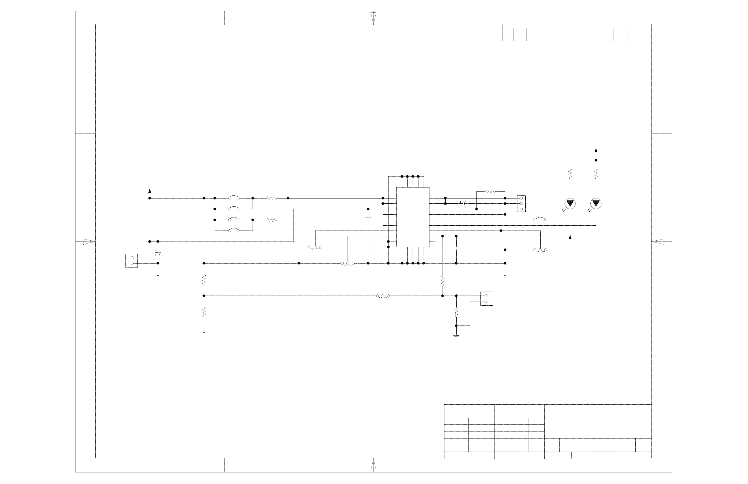
Schematic
This chapter contains the schematic diagram for the EVM.
Topic Page
A.1 Schematic A-2. . . . . . . . . . . . . . . . . . . . . . . . . . . . . . . . . . . . . . . . . . . . . . . . . . . .
Schematic
A-1
Page 19
ZONE APPROVEDDATELTR DESCRIPTION
B
1234
REVISIONS
X X
D
D
VCC
R8
511
C
B
VCC
J3
1 3
B1A1
A2 B2
42
J4
1 3
B1A1
42
A2 B2
J1
1
C1
10UF
2
R2
316K
1%
R1
51.1K
1%
R3
0.1
R4
0.2
2
ON OFF
1
J5
EN JUMPER
3
1
CHG VOLTAGE
C2
0.1UF
2
4.1V4.2V
3
J6
JUMPER
APG MODE THERMISTOR MODE
2
1
J2
APG/THM JUMPER
30
1
N/C
2
IN
3
IN
4
VCC
5
ISNS
6
N/C
7
APG/THM
8
EN
9
VSEL
10
PBKG
2524232221
3
N/C
OUT
OUT
VSENS
AGND
STAT2
STAT1
TMR_SEL
N/C
10PF
1
2
J10
1
2
100
R9
J9
1
2
3
STAT 2 JUMPER
6 Hr 4.5 Hr
3
TMR JUMPER
J8
21
(NO JUMPER)
3 Hr
2
1
J7
20
19
18
17
16
15
14
13
12
CR
11
R5
18.7K
1%
C4
C3
0.22UF
R7
95.3K
1%
16V10UF
C5
U1
BQ24000
26
27
28
29
5%
A
GRN
D2 D1
C
VCC
R6
511
5%
C
A
RED
C
B
A
A
TEXAS INSTRUMENTS
TITLE
DRAWN
S. MCGEE
ENGR
CHK
NEXT ASSY
USED ON
APPLICATION
$1I217
RELEASE
FILE NAME:
DATE
05/23/2000
SCHEMATIC
BQ2400X EVM
SIZE
C
SCALE: NONE
DRAWING DATE
DRAWING NO:CODE REV:
BQ2400X
01/11/2001
1 1
SHEET OF
1234
D
 Loading...