

Texas Instruments PT78ST212V Datasheet
For assistance or to order, call (800) 531-5782
PT78ST200 Series
12V 2 AMP POSITIVE STEP-DOWN
INTEGRATED SWITCHING REGULATOR
Application Notes
Mechanical Outline
Product Selector Guide
Revised 5/15/98
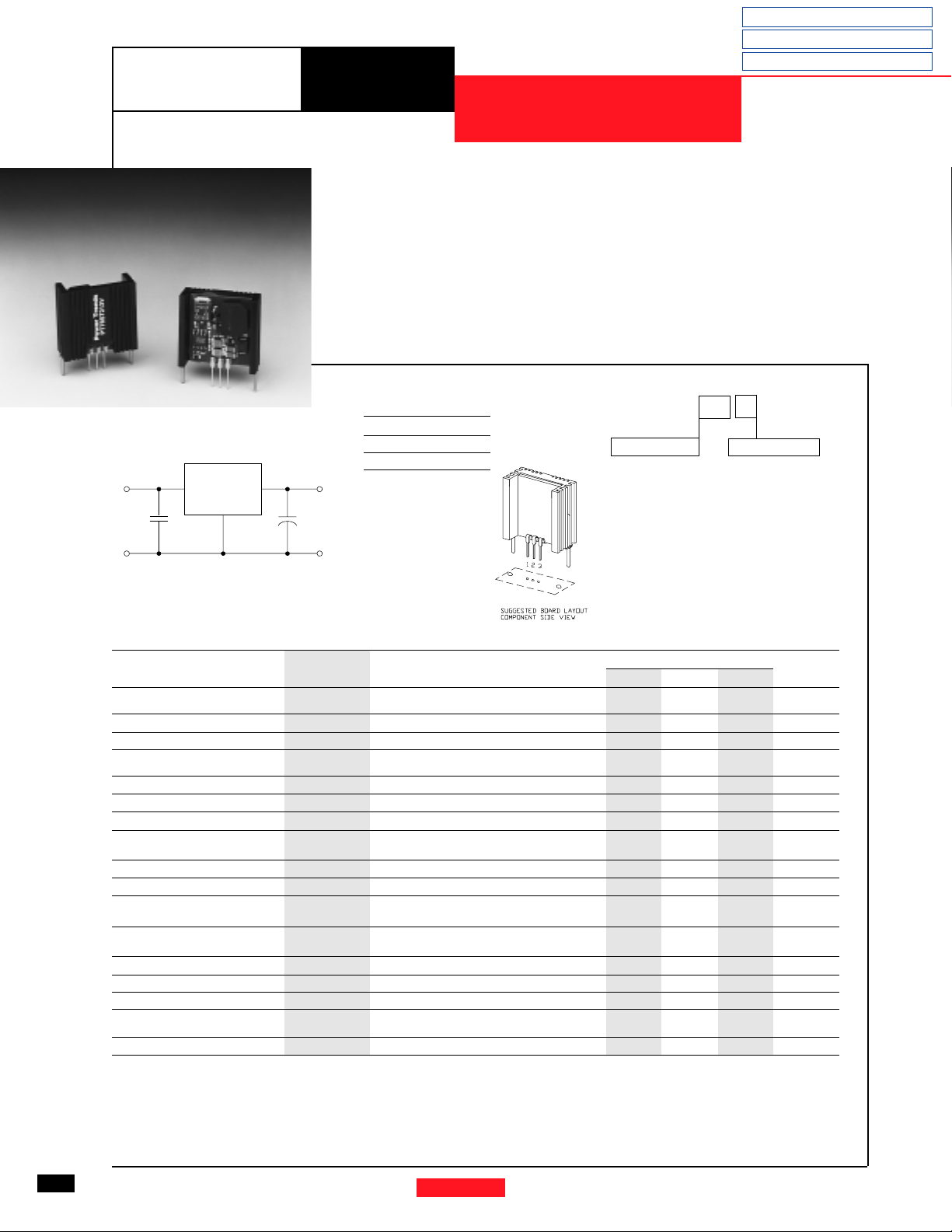
Standard Application
Vin
1
PT78ST200
C1
C1 = Optional 1µF ceramic
C2 = Required 100µF electrolytic
• High Efficiency > 87%
• Wide Input Range
• Aluminum Heatsink for
Applications with Airflow
• Self-Contained Inductor
• Short Circuit Protection
• Over-Temperature Protection
• Pin Compatible with Linear
The Power Trends’ PT78ST200 is
a new 3-terminal Integrated Switching
Regulator (ISR) that can supply up to 24
watts of regulated 12V power. With a
surge capability of 3 Amps and an output voltage that is laser trimmed, it is
ideal for inductive load applications
such as disk drive motors.
3-Terminal, “78” Series Regulators
• Small Footprint
Pin-Out Information
Pin Function
V
1
in
2 GND
V
3
out
Vout
3
C2
+
COMCOM
2
Ordering Information
PT78ST2
Output Voltage
12 = 12.0 Volts
XX Y
Package Suffix
V = Vertical Mount
Specifications
Characteristics
(Ta = 25°C unless noted) Symbols Conditions Min Typ Max Units
Output Current I
Short Circuit Current I
Input Voltage Range V
Output Voltage Tolerance ∆V
Line Regulation Reg
Load Regulation Regload 0.1 ≤ Io ≤ 2.0A — ±0.2 ±0.4 %V
V
Ripple/Noise V
o
Transient Response t
(with 100µF output cap) Vo over/undershoot — 5.0 — %V
Efficiency η Vin=17V, Io=2.0A — 87 — %
Switching Frequency ƒ
Absolute Maximum T
Operating Temperature Range
Recommended Operating T
Temperature Range at Vin= 24V, Io=2A
Thermal Resistance θja Free Air Convection, (40-60LFM) — 35 — °C/W
Storage Temperature T
Mechanical Shock — Per Mil-STD-883D, Method 2002.3 — 500 — G’s
Mechanical Vibration — Per Mil-STD-883D, Method 2007.2,
Weight — — — 11 — Grams
*ISR will operate down to no load with reduced specifications. **See Thermal Derating chart.
Note:
The PT78ST200 Series requires a 100µF electrolytic or tantalum output capacitor for proper operation in all applications.
o
sc
in
o
line
n
tr
o
a
a
s
Over Vin range
With forced air cooling
Vin = V
min — 5.0 — Apk
in
0.1 ≤ Io ≤ 2.0A 16 — 28 V
Over Vin range, Io= 2.0A
Ta= 0°C to +60°C
Over Vin range — ±0.4 ±0.8 %V
Vin=17V, Io=2.0A, Vo=12V — 120 — mV
50% load change — 100 — µSec
Over Vin and Io ranges 0.95 1.0 1.05 MHz
— -40 — +65 °C
Free Air Convection, (40-60LFM)
— -40 — +125 °C
20-2000 Hz, Soldered in a PC board
Pkg Style 600
PT78ST200 SERIES
0.1* — 2.0 A
— ±1.0 ±2.0 %Vo
-40 — +55** °C
—10
—
o
o
pp
o
G’s
18
Power Trends, Inc. 27715 Diehl Road, Warrenville, IL 60555 (800) 531-5782 Fax: (630) 393-6902 http://www.powertrends.com
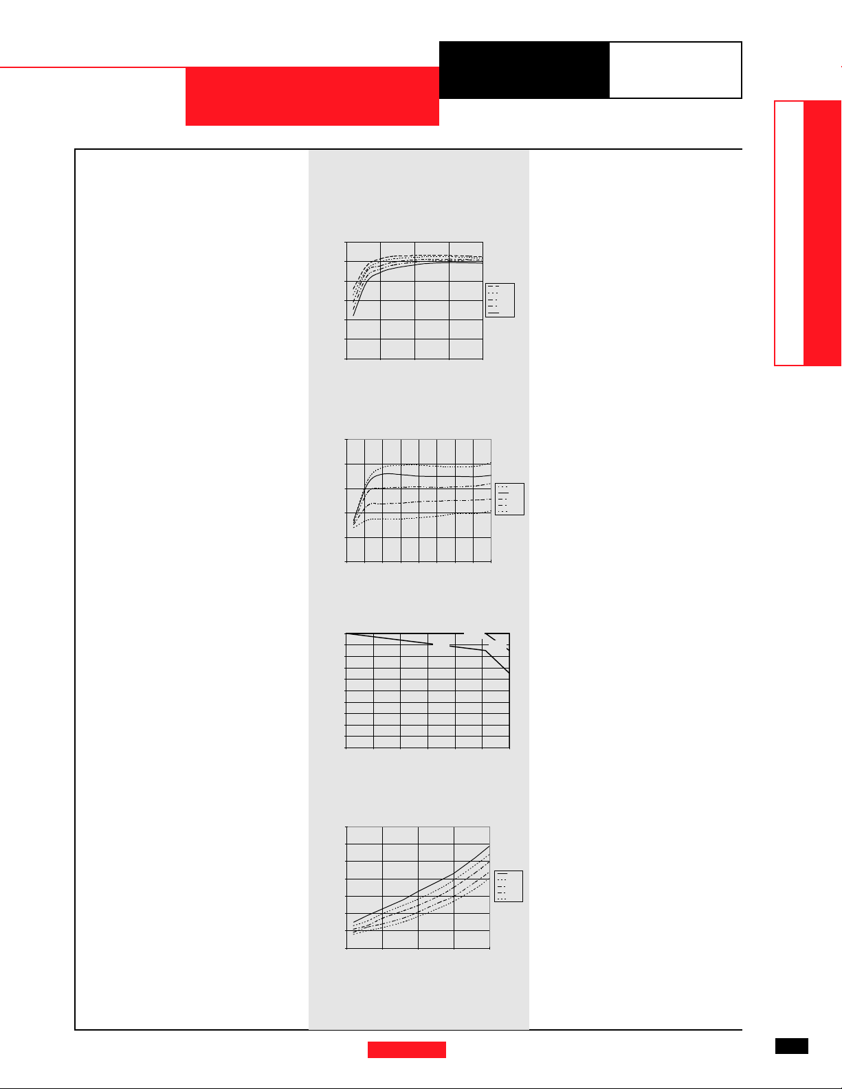
CHARACTERISTIC DATA
PT78ST212 12.0 VDC (See Note 1)
Efficiency vs Output Current
100
90
80
70
Efficiency - %Ripple-(mV)Iout-(Amps)PD-(Watts)
60
50
40
00.511.52
Iout-(Amps)
Ripple vs Output Current
100
For assistance or to order, call (800) 531-5782
PT78ST200 Series
Vin
16.0V
18.0V
21.0V
24.0V
28.0V
Wide Input Range Products
DATA SHEETS
80
60
40
20
0
0 0.25 0.5 0.75 1 1.25 1.5 1.75 2
Iout-(Amps)
Thermal Derating (Ta) (See Note 2)
2
1.8
1.6
1.4
1.2
1
0.8
0.6
0.4
0.2
0
16 18 20 22 24 26 28
Vin-(Volts)
45°C
65°C
Power Dissipation vs Output Current
3.5
3
2.5
2
1.5
1
0.5
0
0 0.5 1 1.5 2
`
Iout-(Amps)
55°C
Vin
28.0V
24.0V
21.0V
18.0V
16.0V
Vin
28.0V
24.0V
21.0V
18.0V
16.0V
Note 1: All data listed in the above graphs, except for derating data, has been developed from actual products tested at 25°C. This data is considered typical data for the ISR.
Note 2: Thermal derating graphs are developed in free air convection cooling of 40-60 LFM. (See Thermal Application Notes.)
Power Trends, Inc. 27715 Diehl Road, Warrenville, IL 60555 (800) 531-5782 Fax: (630) 393-6902 http://www.powertrends.com
19
 Loading...